Embed Size (px)
Citation preview
Indian Journal of Radio & Space Physics
Vol. 49, September 2020, pp. 79-97
Multiband reconfigurable antennas for future wireless communication systems
Kusum Dalal*, Tejbir Singh & Pawan Kumar Singh
Electronics & Communication Engineering Department, SRM University, Sonipat, Haryana 131 023, India
Accepted: 25 February 2020; accepted: 7 September 2020
Evolution in wireless technology has resulted in remarkable capabilities, but ever increasing user demand and limited
bandwidth spectrum has always instigated the researchers to think of new techniques that can improve network efficiency in
terms of size, power and bandwidth consumption. Antenna designing is one of the key factors in achieving this goal and as a
result plethora of research work has been conducted in past for crafting sustainable reconfigurable multiband antennas for
different wireless services. The concept of combining the wideband-narrowband reconfiguration functionality into a single
antenna has created an effective solution for optimizing antenna size and enhancing flexibility in antenna designing.
Moreover; this combination has offered the advantage of pre-filtering, which has helped in mitigating the level of
interference at the receiver end and has provided an edge over the fixed or non-reconfigurable transceivers. This paper has
presented a detailed outlook about reconfigurable antennas and the various techniques involved in attaining reconfigurability
in antenna design. The review has been supported by some antenna designs and simulation results that have provided
an insight into reconfiguration features. Some new technologies employed in antenna design have also been briefly presented.
Keywords: Wideband antennas, Multiband antennas, Reconfiguration techniques for antennas, Switching devices, Radiation pattern, Feeding structures
1 Introduction The antenna has been in use for transmitting
and receiving radio signals for more than the last
100 years, and still a significant scope exists for
further research in this area. Hein-rich Hertz in 1887
devised some experiments in order to test some
hypothesis of J.C. Maxwell, as a consequence of
which the first antenna came to the limelight. A flat
dipole is used by Hertz as a radiating antenna and for
reception purpose a single turn loop antenna is
utilized in his experimental setup. Later the antenna
technology was dedicated to the use of wires for
making radiating structures that were supported by
wooden poles and this was continued for almost fifty
years or so. The initial time antennas were
characterized by narrow band features in which array
synthesis principles were adopted to enhance the
directivity of resulting radiation patterns. H. Yagi and
S. Uda in 1926 proposed Yagi-Uda antenna that
offered high directivity and found many applications
in communication industry.
In traditional fixed RF/microwave wireless
communication systems operating on predefined
frequency bands, the antennas and filters acts as the
main components for the front-end circuitry.
Bandwidth, radiation pattern, gain, reflection
coefficients and polarization are some of the
parameters that define these circuit components. In
recently developed technologies such as satellite,
radar, unmanned airborne vehicles, microwave
imaging, cognitive radio system there is an utmost
requirement for flexibility that can aid in
accommodating variable number of wireless standards
such as: Bluetooth, UWB, WiMAX, Wi-Fi, WLAN,
UMTS etc. According to Jackson et al.1 the antenna,
as a front-end circuit in RF/microwave system, is a
very useful device for selecting or rejecting the
signals at various frequencies in various modern
wireless application systems. Due to the limitation of
the frequency spectrum, designing of RF/microwave
reconfigurable antenna with linear phase, low
insertion loss, lightweight, small size, high selectivity
and lower cost, pose a continuous challenge to the
researchers and developers1-2
.
The reconfiguration attribute can be claimed as the
capability of an individual radiator system to vary its
operating characteristics by making changes in its
electrical, mechanical, or material characteristics.
Reconfigurable antennas have potential of altering
operating frequencies, radiation pattern, polarization ——————
*Corresponding author (E-mail: [email protected])
80 INDIAN J RADIO SPACE PHYS, VOL 49, SEPTEMBER 2020
and impedance bandwidth independently as per the
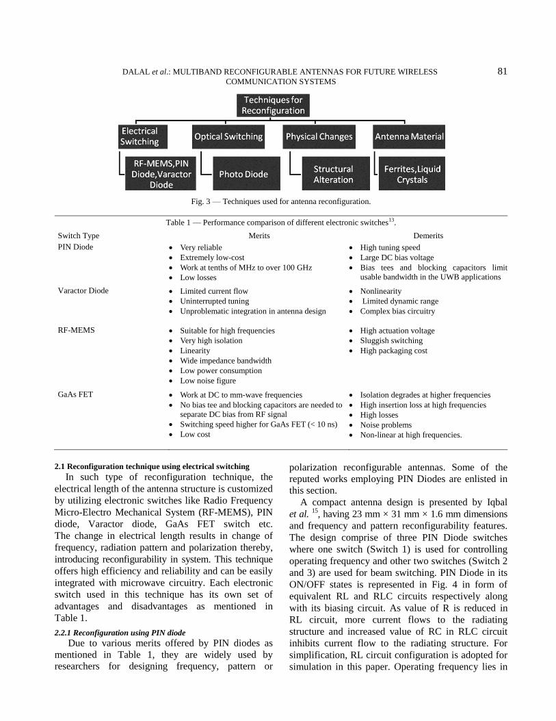
desired application. The types of reconfigurations
possible are illustrated in Fig. 1. Frequency reconfiguration eliminates the need for
having multiple antennas for providing different
services operating on different frequencies and
thereby helps in reducing circuit complexity and cost.
The frequency reconfigurable antenna has been
categorized into two types: one which follows
continuous frequency tuning that permits smooth
transformations among operating frequencies without
noticeable hiccups; the second type follows switched
tuning, in which, the antennas work in distinct
frequency bands on the basis of switching
mechanism. In general, both the categories share a
common theory of reconfigurable operation3-6
. Over
the years, large numbers of reconfigurable antennas
have been designed that showed switching
capabilities among two particular narrowband
frequencies7-8
.
The compact wideband-narrowband reconfigurable
antenna is extremely useful in terms of its capability to
operate on multiband frequencies. This approach has
significant advantages over fixed or non-reconfigurable
transceivers9-11
, by offering pre-filtering feature. The
multiband reconfigurable antenna is a viable solution for
the challenges posed in antenna designing such as
accommodating ever increasing number of users in
limited frequency spectrum12
. In applications involving
surveillance or tracking, pattern reconfiguration can be
used for producing desired radiation patterns with
variable directivity without introducing any shift in
frequency. Diverse radiation patterns also help in
mitigating problems resulting from random noise
sources and electronic jammers; thereby improving
security, reliability and energy efficiency. Polarization
reconfiguration can be achieved by initiating switching
among horizontal and vertical linear polarizations or
among right-hand circular polarization (RHCP) and left-
hand circular polarization (LHCP) and among elliptical
polarizations13
. Hybrid reconfiguration employs
combination of above mentioned reconfiguration types
to enhance the network performance for desired service.
A detailed review about the reconfiguration techniques
(that helps in attaining the goal of reconfiguration in
terms of frequency, pattern, polarization or their
combination) is provided in section 2. The use of some
emerging technologies in antenna design is briefed in
section 3. Section 4 highlights the future prospects of
reconfigurable antennas and section 5 present summary
of the paper.
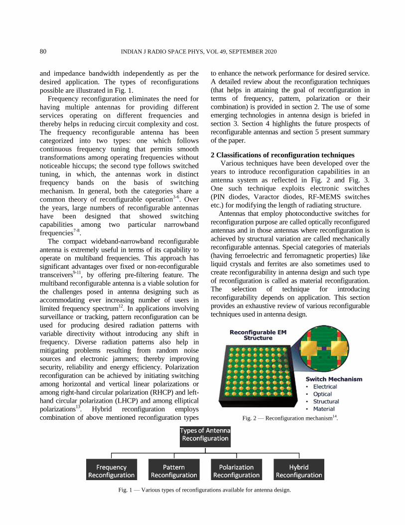
2 Classifications of reconfiguration techniques
Various techniques have been developed over the
years to introduce reconfiguration capabilities in an
antenna system as reflected in Fig. 2 and Fig. 3.
One such technique exploits electronic switches
(PIN diodes, Varactor diodes, RF-MEMS switches
etc.) for modifying the length of radiating structure.
Antennas that employ photoconductive switches for
reconfiguration purpose are called optically reconfigured
antennas and in those antennas where reconfiguration is
achieved by structural variation are called mechanically
reconfigurable antennas. Special categories of materials
(having ferroelectric and ferromagnetic properties) like
liquid crystals and ferrites are also sometimes used to
create reconfigurability in antenna design and such type
of reconfiguration is called as material reconfiguration.
The selection of technique for introducing
reconfigurability depends on application. This section
provides an exhaustive review of various reconfigurable
techniques used in antenna design.
Fig. 1 — Various types of reconfigurations available for antenna design.
Fig. 2 — Reconfiguration mechanism14.
DALAL et al.: MULTIBAND RECONFIGURABLE ANTENNAS FOR FUTURE WIRELESS 81 COMMUNICATION SYSTEMS
2.1 Reconfiguration technique using electrical switching
In such type of reconfiguration technique, the
electrical length of the antenna structure is customized
by utilizing electronic switches like Radio Frequency
Micro-Electro Mechanical System (RF-MEMS), PIN
diode, Varactor diode, GaAs FET switch etc.
The change in electrical length results in change of
frequency, radiation pattern and polarization thereby,
introducing reconfigurability in system. This technique
offers high efficiency and reliability and can be easily
integrated with microwave circuitry. Each electronic
switch used in this technique has its own set of
advantages and disadvantages as mentioned in
Table 1.
2.2.1 Reconfiguration using PIN diode
Due to various merits offered by PIN diodes as
mentioned in Table 1, they are widely used by
researchers for designing frequency, pattern or
polarization reconfigurable antennas. Some of the
reputed works employing PIN Diodes are enlisted in
this section.
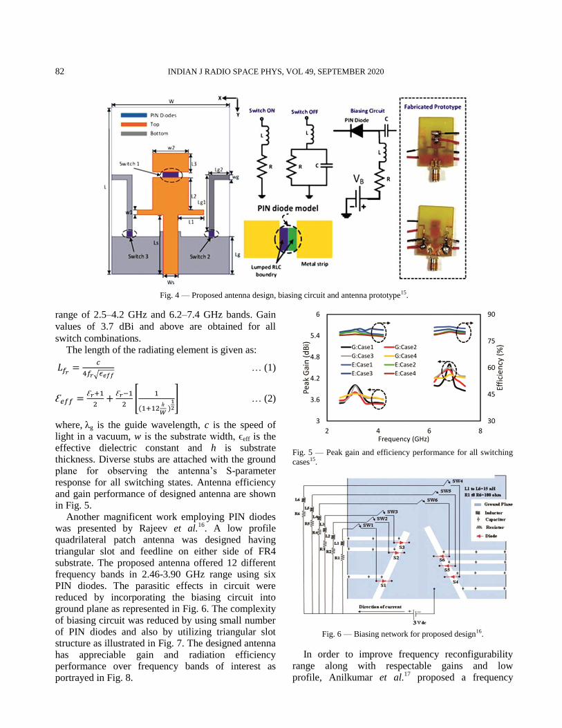
A compact antenna design is presented by Iqbal
et al. 15
, having 23 mm × 31 mm × 1.6 mm dimensions
and frequency and pattern reconfigurability features.
The design comprise of three PIN Diode switches
where one switch (Switch 1) is used for controlling
operating frequency and other two switches (Switch 2
and 3) are used for beam switching. PIN Diode in its
ON/OFF states is represented in Fig. 4 in form of
equivalent RL and RLC circuits respectively along
with its biasing circuit. As value of R is reduced in
RL circuit, more current flows to the radiating
structure and increased value of RC in RLC circuit
inhibits current flow to the radiating structure. For
simplification, RL circuit configuration is adopted for
simulation in this paper. Operating frequency lies in
Fig. 3 — Techniques used for antenna reconfiguration.
Table 1 — Performance comparison of different electronic switches13.
Switch Type Merits Demerits
PIN Diode Very reliable
Extremely low-cost
Work at tenths of MHz to over 100 GHz
Low losses
High tuning speed
Large DC bias voltage
Bias tees and blocking capacitors limit
usable bandwidth in the UWB applications
Varactor Diode Limited current flow
Uninterrupted tuning
Unproblematic integration in antenna design
Nonlinearity
Limited dynamic range
Complex bias circuitry
RF-MEMS Suitable for high frequencies
Very high isolation
Linearity
Wide impedance bandwidth
Low power consumption
Low noise figure
High actuation voltage
Sluggish switching
High packaging cost
GaAs FET Work at DC to mm-wave frequencies
No bias tee and blocking capacitors are needed to
separate DC bias from RF signal
Switching speed higher for GaAs FET (< 10 ns)
Low cost
Isolation degrades at higher frequencies
High insertion loss at high frequencies
High losses
Noise problems
Non-linear at high frequencies.
82 INDIAN J RADIO SPACE PHYS, VOL 49, SEPTEMBER 2020
range of 2.5–4.2 GHz and 6.2–7.4 GHz bands. Gain
values of 3.7 dBi and above are obtained for all
switch combinations. The length of the radiating element is given as:
… (1)
… (2)
where, λg is the guide wavelength, c is the speed of light in a vacuum, w is the substrate width, ϵeff is the effective dielectric constant and h is substrate thickness. Diverse stubs are attached with the ground plane for observing the antenna’s S-parameter
response for all switching states. Antenna efficiency and gain performance of designed antenna are shown in Fig. 5.
Another magnificent work employing PIN diodes was presented by Rajeev et al.
16. A low profile
quadrilateral patch antenna was designed having
triangular slot and feedline on either side of FR4 substrate. The proposed antenna offered 12 different frequency bands in 2.46-3.90 GHz range using six PIN diodes. The parasitic effects in circuit were reduced by incorporating the biasing circuit into ground plane as represented in Fig. 6. The complexity
of biasing circuit was reduced by using small number of PIN diodes and also by utilizing triangular slot structure as illustrated in Fig. 7. The designed antenna has appreciable gain and radiation efficiency performance over frequency bands of interest as portrayed in Fig. 8.
Fig. 5 — Peak gain and efficiency performance for all switching
cases15.
Fig. 6 — Biasing network for proposed design16.
In order to improve frequency reconfigurability
range along with respectable gains and low
profile, Anilkumar et al.17
proposed a frequency
Fig. 4 — Proposed antenna design, biasing circuit and antenna prototype15.
DALAL et al.: MULTIBAND RECONFIGURABLE ANTENNAS FOR FUTURE WIRELESS 83 COMMUNICATION SYSTEMS
reconfigurable antenna that operates in S-band of 2-4
GHz range and C-band that is in range of 4-8 GHz,
having circular ring- shaped radiating patch attached
to a pair of connected circle using two PIN Diodes as
shown in Fig. 9. Such antenna has showed application
for vehicular communication in an Internet of Things
(Vehicles) environment. The FR4 substrate is used for
antenna fabrication having dimensions 40×30×1.6
mm3. Peak gain of more than 1.3 dB in S-band and
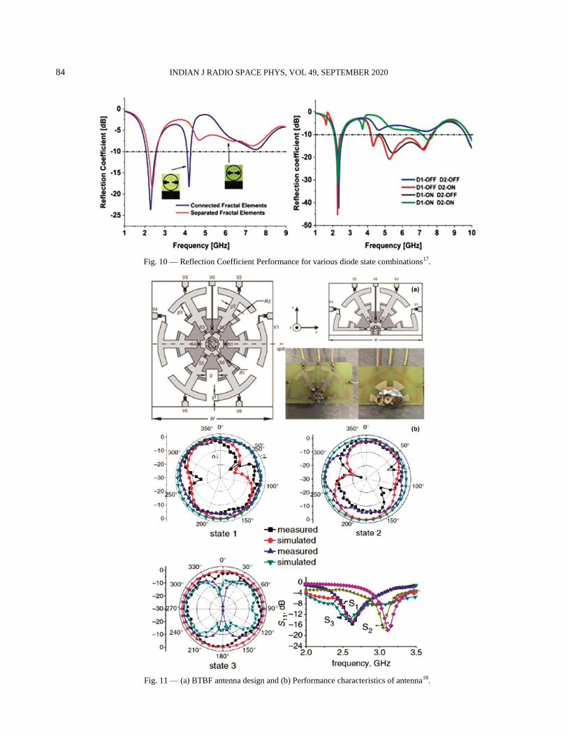
more than 3.5 dB in C-band were obtained. Reflection
coefficient performances for various diode state
combinations are shown in Fig. 10.
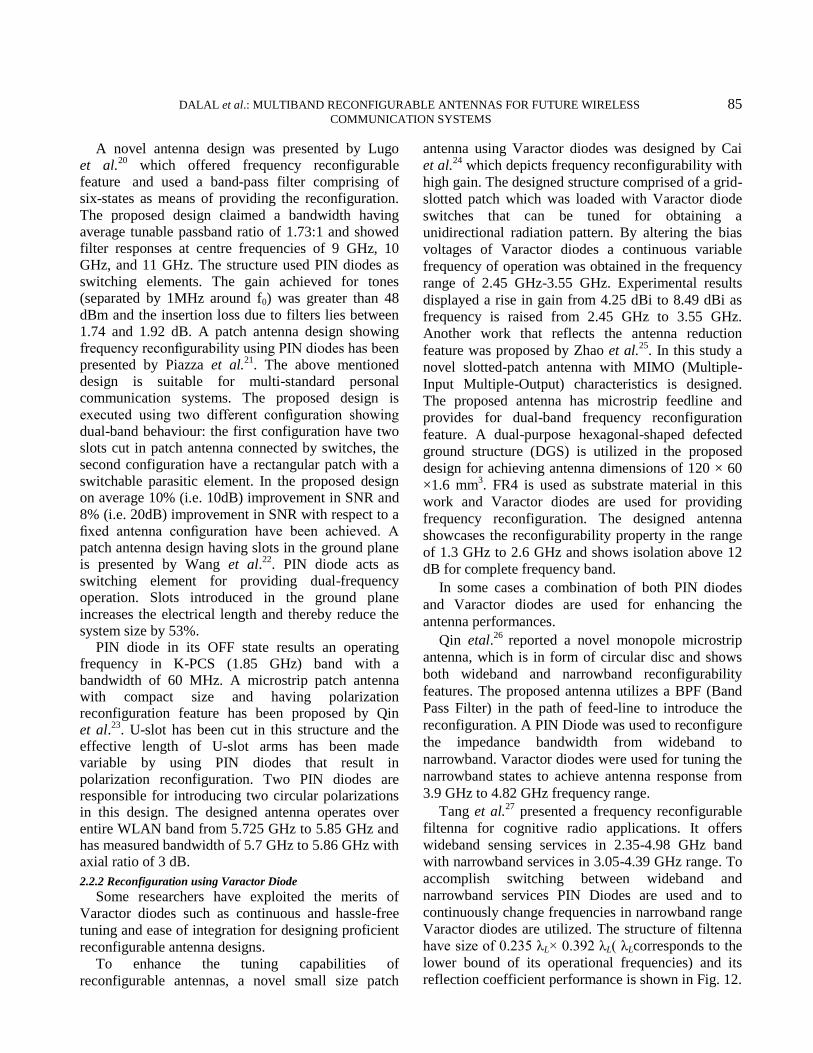
A novel antenna design was presented by Ye
et al.18
which showed pattern and frequency
reconfiguration characteristics. The proposed antenna
was a back-to-back F (BTBF) semicircular antenna
with centre feed. Four PIN diodes were connected
with four BTBF elements to produce three operating
states. Two states operate in frequency range of 2.51
GHz to 2.76 GHz and one state operates in 3.01 GHz-
3.23 GHz range. Different radiation patterns were
achieved for all three states as noticed from
Fig. 11(b). Also as can be seen from Fig. 11(a), the
semicircular BTBF antenna was obtained by half-
cutting a circular BTBF antenna and due to symmetry
the native radiation characteristics of circular BTBF
were retained with appreciable reduction in structure
size and cost.
A compact, efficient and electronically tunable antenna has been designed and presented by Peroulis et al.
19. The proposed fundamental structure has a
single-fed slot resonator. The reconfiguration feature is provided using four PIN diodes such that the radiating structure can be tuned to an overall
frequency range of 540MHz to 950 MHz. A better return loss (-20 dB) has been observed which proves the best impedance matching for the operating frequency band along with measured gain of 11 dBi, which reflect an antenna efficiency of 47%.
Fig. 7 — Proposed antenna front view16.
Fig. 8 — Measured and simulated results for gain and radiation efficiency16.
Fig. 9 — Prototype of proposed circular ring- shaped radiating
patch antenna17.
84 INDIAN J RADIO SPACE PHYS, VOL 49, SEPTEMBER 2020
Fig. 10 — Reflection Coefficient Performance for various diode state combinations17.
Fig. 11 — (a) BTBF antenna design and (b) Performance characteristics of antenna18.
DALAL et al.: MULTIBAND RECONFIGURABLE ANTENNAS FOR FUTURE WIRELESS 85 COMMUNICATION SYSTEMS
A novel antenna design was presented by Lugo et al.
20 which offered frequency reconfigurable
feature and used a band-pass filter comprising of six-states as means of providing the reconfiguration.
The proposed design claimed a bandwidth having average tunable passband ratio of 1.73:1 and showed filter responses at centre frequencies of 9 GHz, 10 GHz, and 11 GHz. The structure used PIN diodes as switching elements. The gain achieved for tones (separated by 1MHz around f0) was greater than 48
dBm and the insertion loss due to filters lies between 1.74 and 1.92 dB. A patch antenna design showing frequency reconfigurability using PIN diodes has been presented by Piazza et al.
21. The above mentioned
design is suitable for multi-standard personal communication systems. The proposed design is
executed using two different configuration showing dual-band behaviour: the first configuration have two slots cut in patch antenna connected by switches, the second configuration have a rectangular patch with a switchable parasitic element. In the proposed design on average 10% (i.e. 10dB) improvement in SNR and
8% (i.e. 20dB) improvement in SNR with respect to a fixed antenna configuration have been achieved. A patch antenna design having slots in the ground plane is presented by Wang et al.
22. PIN diode acts as
switching element for providing dual-frequency operation. Slots introduced in the ground plane
increases the electrical length and thereby reduce the system size by 53%.
PIN diode in its OFF state results an operating frequency in K-PCS (1.85 GHz) band with a bandwidth of 60 MHz. A microstrip patch antenna with compact size and having polarization reconfiguration feature has been proposed by Qin et al.
23. U-slot has been cut in this structure and the
effective length of U-slot arms has been made variable by using PIN diodes that result in polarization reconfiguration. Two PIN diodes are responsible for introducing two circular polarizations in this design. The designed antenna operates over entire WLAN band from 5.725 GHz to 5.85 GHz and has measured bandwidth of 5.7 GHz to 5.86 GHz with axial ratio of 3 dB.
2.2.2 Reconfiguration using Varactor Diode
Some researchers have exploited the merits of
Varactor diodes such as continuous and hassle-free
tuning and ease of integration for designing proficient
reconfigurable antenna designs.
To enhance the tuning capabilities of
reconfigurable antennas, a novel small size patch
antenna using Varactor diodes was designed by Cai
et al.24
which depicts frequency reconfigurability with
high gain. The designed structure comprised of a grid-
slotted patch which was loaded with Varactor diode
switches that can be tuned for obtaining a
unidirectional radiation pattern. By altering the bias
voltages of Varactor diodes a continuous variable
frequency of operation was obtained in the frequency
range of 2.45 GHz-3.55 GHz. Experimental results
displayed a rise in gain from 4.25 dBi to 8.49 dBi as
frequency is raised from 2.45 GHz to 3.55 GHz.
Another work that reflects the antenna reduction
feature was proposed by Zhao et al.25
. In this study a
novel slotted-patch antenna with MIMO (Multiple-
Input Multiple-Output) characteristics is designed.
The proposed antenna has microstrip feedline and
provides for dual-band frequency reconfiguration
feature. A dual-purpose hexagonal-shaped defected
ground structure (DGS) is utilized in the proposed
design for achieving antenna dimensions of 120 × 60
×1.6 mm3. FR4 is used as substrate material in this
work and Varactor diodes are used for providing
frequency reconfiguration. The designed antenna
showcases the reconfigurability property in the range
of 1.3 GHz to 2.6 GHz and shows isolation above 12
dB for complete frequency band.
In some cases a combination of both PIN diodes
and Varactor diodes are used for enhancing the
antenna performances.
Qin etal.26
reported a novel monopole microstrip
antenna, which is in form of circular disc and shows
both wideband and narrowband reconfigurability
features. The proposed antenna utilizes a BPF (Band
Pass Filter) in the path of feed-line to introduce the
reconfiguration. A PIN Diode was used to reconfigure
the impedance bandwidth from wideband to
narrowband. Varactor diodes were used for tuning the
narrowband states to achieve antenna response from
3.9 GHz to 4.82 GHz frequency range.
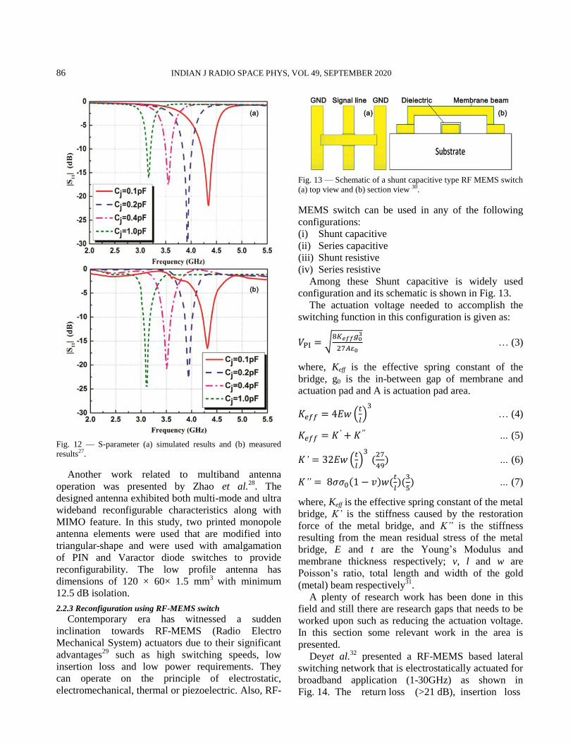
Tang et al.27
presented a frequency reconfigurable
filtenna for cognitive radio applications. It offers
wideband sensing services in 2.35-4.98 GHz band
with narrowband services in 3.05-4.39 GHz range. To
accomplish switching between wideband and
narrowband services PIN Diodes are used and to
continuously change frequencies in narrowband range
Varactor diodes are utilized. The structure of filtenna
have size of 0.235 λL× 0.392 λL( λLcorresponds to the
lower bound of its operational frequencies) and its
reflection coefficient performance is shown in Fig. 12.
86 INDIAN J RADIO SPACE PHYS, VOL 49, SEPTEMBER 2020
Fig. 12 — S-parameter (a) simulated results and (b) measured
results27.
Another work related to multiband antenna
operation was presented by Zhao et al.28
. The
designed antenna exhibited both multi-mode and ultra
wideband reconfigurable characteristics along with
MIMO feature. In this study, two printed monopole
antenna elements were used that are modified into
triangular-shape and were used with amalgamation
of PIN and Varactor diode switches to provide
reconfigurability. The low profile antenna has
dimensions of 120 × 60× 1.5 mm3
with minimum
12.5 dB isolation.
2.2.3 Reconfiguration using RF-MEMS switch
Contemporary era has witnessed a sudden
inclination towards RF-MEMS (Radio Electro
Mechanical System) actuators due to their significant
advantages29
such as high switching speeds, low
insertion loss and low power requirements. They
can operate on the principle of electrostatic,
electromechanical, thermal or piezoelectric. Also, RF-
MEMS switch can be used in any of the following
configurations:
(i) Shunt capacitive
(ii) Series capacitive
(iii) Shunt resistive
(iv) Series resistive
Among these Shunt capacitive is widely used
configuration and its schematic is shown in Fig. 13.
The actuation voltage needed to accomplish the
switching function in this configuration is given as:
… (3)
where, Keff is the effective spring constant of the
bridge, g0 is the in-between gap of membrane and
actuation pad and A is actuation pad area.
… (4)
… (5)
… (6)
… (7)
where, Keff is the effective spring constant of the metal
bridge, K is the stiffness caused by the restoration
force of the metal bridge, and K is the stiffness
resulting from the mean residual stress of the metal
bridge, E and t are the Young’s Modulus and
membrane thickness respectively; v, l and w are
Poisson’s ratio, total length and width of the gold
(metal) beam respectively31
.
A plenty of research work has been done in this
field and still there are research gaps that needs to be
worked upon such as reducing the actuation voltage.
In this section some relevant work in the area is
presented.
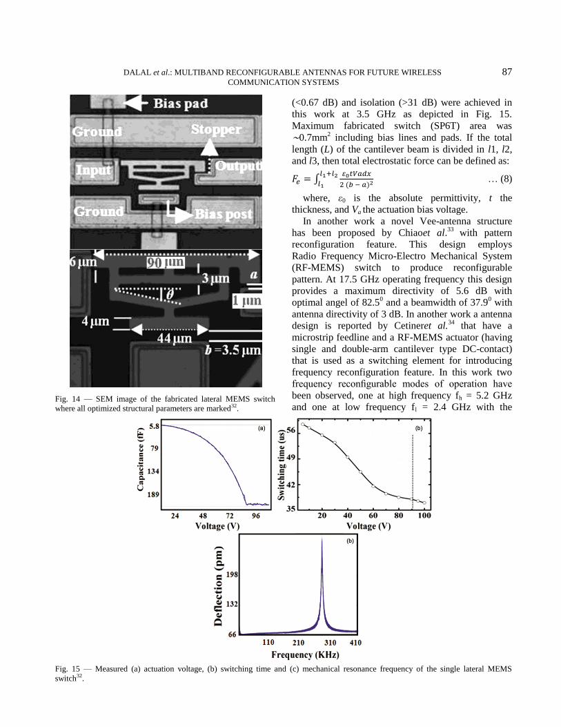
Deyet al.32
presented a RF-MEMS based lateral
switching network that is electrostatically actuated for
broadband application (1-30GHz) as shown in
Fig. 14. The return loss (>21 dB), insertion loss
Fig. 13 — Schematic of a shunt capacitive type RF MEMS switch
(a) top view and (b) section view 30.
DALAL et al.: MULTIBAND RECONFIGURABLE ANTENNAS FOR FUTURE WIRELESS 87 COMMUNICATION SYSTEMS
(<0.67 dB) and isolation (>31 dB) were achieved in
this work at 3.5 GHz as depicted in Fig. 15.
Maximum fabricated switch (SP6T) area was
∼0.7mm2 including bias lines and pads. If the total
length (L) of the cantilever beam is divided in l1, l2,
and l3, then total electrostatic force can be defined as:
… (8)
where, ε0 is the absolute permittivity, t the
thickness, and Va the actuation bias voltage.
In another work a novel Vee-antenna structure
has been proposed by Chiaoet al.33
with pattern
reconfiguration feature. This design employs
Radio Frequency Micro-Electro Mechanical System
(RF-MEMS) switch to produce reconfigurable
pattern. At 17.5 GHz operating frequency this design
provides a maximum directivity of 5.6 dB with
optimal angel of 82.50 and a beamwidth of 37.9
0 with
antenna directivity of 3 dB. In another work a antenna
design is reported by Cetineret al.34
that have a
microstrip feedline and a RF-MEMS actuator (having
single and double-arm cantilever type DC-contact)
that is used as a switching element for introducing
frequency reconfiguration feature. In this work two
frequency reconfigurable modes of operation have
been observed, one at high frequency fh = 5.2 GHz
and one at low frequency fl = 2.4 GHz with the
Fig. 14 — SEM image of the fabricated lateral MEMS switch
where all optimized structural parameters are marked32.
Fig. 15 — Measured (a) actuation voltage, (b) switching time and (c) mechanical resonance frequency of the single lateral MEMS
switch32.
88 INDIAN J RADIO SPACE PHYS, VOL 49, SEPTEMBER 2020
frequency bandwidths of 100 MHz and 650 MHz
respectively.
Guo et al.35
described the behavior of a triangular
shaped Sierpinski fractal antenna having multiband. A
comparison was also drawn among proposed antenna
and bow-tie antenna which is inherently single band.
The numerical and empirical results have shown the
similar fractal property transfer in the form of
electromagnetic behavior. Also for controlling the
antenna components RF-MEMS switches were used.
Kingsley et al.36
proposed a Sierpinski multiband
fractal antenna design in which RF-MEMS switches
were used in set of three for activating and
deactivating the antenna as per applied voltage
conditions. Using such method of feeding the signal
directly using electrostatic action present in RF-
MEMS switches eliminated the requirement of
individual bias lines for switching by compromising
the different bias voltages applied.
Some correlated work of RF-MEMS switches with microstrip antenna has been judiciously carried out in a work presented by Zhou et al.
37. A low-voltage RF-
MEMS switch contact has been designed to drive reconfigurability using a rectangular microstrip antenna coil, which provides a frequency tuning capability. In order to optimize the electromechanical design, micro-fabrication was done using commercial poly-MUMPS and results were derived using RF
simulations. The designed RF-MEMS based frequency tunable microstrip coil antenna has been investigated using the electromagnetic simulation tool, which is based on full wave analysis.
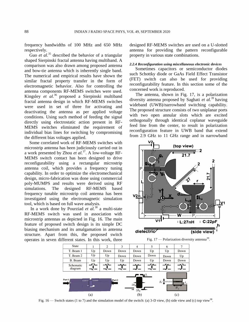
In a work done by Pourziad et al.38
a multi-state
RF-MEMS switch was used in association with
microstrip antennas as depicted in Fig. 16. The main
feature of proposed switch design is its simple DC
biasing mechanism and its amalgamation in antenna
structure. Apart from this, the proposed switch
operates in seven different states. In this work, three
designed RF-MEMS switches are used on a U-slotted
antenna for providing the pattern reconfigurable
property in various state combinations.
2.2.4 Reconfiguration using miscellaneous electronic devices
Sometimes capacitors or semiconductor diodes
such Schottky diode or GaAs Field Effect Transistor
(FET) switch can also be used for providing
reconfigurability feature. In this section some of the
concerned work is reproduced.
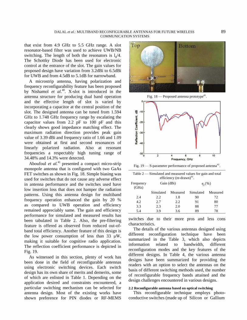
The antenna, shown in Fig. 17, is a polarization
diversity antenna proposed by Saghati et al.39
having
wideband (UWB)/narrowband switching capability.
The proposed structure consists of two uniplanar ports
with two open annular slots which are excited
orthogonally through identical coplanar waveguide
feed line from the center, to result in polarization
reconfiguration feature in UWB band that extend
from 2.9 GHz to 11 GHz range and in narrowband
Fig. 16 — Switch states (1 to 7) and the simulation model of the switch: (a) 3-D view, (b) side view and (c) top view38.
Fig. 17 — Polarization diversity antenna39.
DALAL et al.: MULTIBAND RECONFIGURABLE ANTENNAS FOR FUTURE WIRELESS 89 COMMUNICATION SYSTEMS
that exist from 4.9 GHz to 5.5 GHz range. A slot
resonator-based filter was used to achieve UWB/NB
switching. The length of both the resonators is lg/4.
The Schottky Diode has been used for electronic
control at the entrance of the slot. The gain values for
proposed design have variation from 3.2dBi to 6.5dBi
for UWB and from 4.5dB to 5.1dB for narrowband.
A microstrip antenna, having polarization and
frequency reconfigurability feature has been proposed
by Nishamol et al.40
. X-slot is introduced in the
antenna structure for producing dual band operation
and the effective length of slot is varied by
incorporating a capacitor at the central position of the
slot. The designed antenna can be tuned from 1.594
GHz to 1.748 GHz frequency range by escalating the
capacitor values from 2.2 pF to 100 pF and this
clearly shows good impedance matching effect. The
maximum radiation direction provides peak gain
value of 3.39 dBi and frequency ratio of 1.66 and 1.09
were obtained at first and second resonances of
linearly polarized radiation. Also at resonant
frequencies a respectably high tuning range of
34.48% and 14.3% were detected.
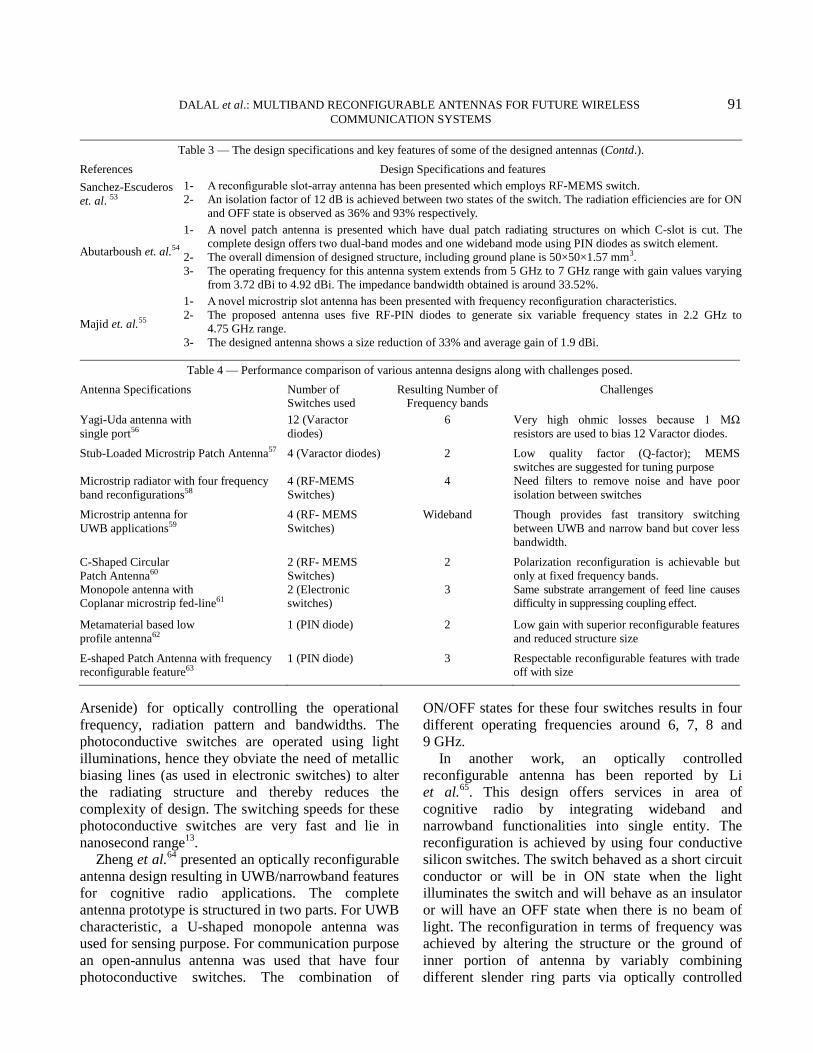
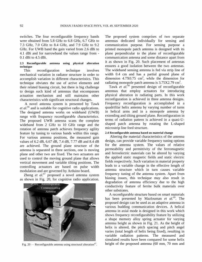
Aboufoul et al.41
presented a compact micro-strip
monopole antenna that is configured with two GaAs
FET switches as shown in Fig. 18. Simple biasing was
used for switches that do not cause any adverse effect
in antenna performance and the switches used have
low insertion loss that does not hamper the radiation
patterns. Using this antenna design for multiband
frequency operation enhanced the gain by 20 %
as compared to UWB operation and efficiency
remained appreciably same. The gain and efficiency
performance for simulated and measured results has
been tabulated in Table 2. Also, the pre-filtering
feature is offered as observed from reduced out-of-
band total efficiency. Another feature of this design is
the low power consumption of less than 33 μW,
making it suitable for cognitive radio application.
The reflection coefficient performance is depicted in
Fig. 19.
As witnessed in this section, plenty of work has
been done in the field of reconfigurable antennas
using electronic switching devices. Each switch
design has its own share of merits and demerits, some
of which are enlisted in Table 1. Depending on the
application desired and constraints encountered, a
particular switching mechanism can be selected for
antenna design. Most of the existing works have
shown preference for PIN diodes or RF-MEMS
switches due to their more pros and less cons
characteristics.
The details of the various antennas designed using
different reconfiguration technique have been
summarized in the Table 3, which also depicts
information related to bandwidth, different
reconfiguration modes and the key features of the
different designs. In Table 4, the various antenna
designs have been summarized for providing the
readers with an option to select the antennas on the
basis of different switching methods used, the number
of reconfigurable frequency bands attained and the
design challenges encountered in various designs.
2.2 Reconfigurable antenna based on optical switching
This reconfigurable technique employs photo-
conductive switches (made up of Silicon or Gallium
Fig. 18 — Proposed antenna prototype41.
Fig. 19 — S-parameter performance of proposed antenna41.
Table 2 — Simulated and measured values for gain and total
efficiency (re-drawn)41.
Frequency
(GHz)
Gain (dBi)
Simulated Measured Simulated Measured
2.4 2.2 1.8 90 72
4.2 2.7 2.2 91 80
3.3 2.3 2.0 88 77
5.4 3.9 3.6 89 78

90 INDIAN J RADIO SPACE PHYS, VOL 49, SEPTEMBER 2020
Table 3 — The design specifications and key features of some of the designed antennas.
References Design Specifications and features
Yang et. al42
1- The proposed design shows reconfigurability feature in terms of polarization and frequency and also features
bandwidth enhancement.
2- The design achieves 3% CP bandwidth (for both RHCP & LHCP pattern.
3- As per the state of switch (ON or OFF), the axial ratios achieved are 2.9 dB and 1.6 dB at 4.0 GHz and
4.37 GHz frequencies respectively.
Jung et. al.43
1- A novel antenna design having two rectangular patches and showing frequency reconfigurable property has
been proposed.
2- Both patches have been printed on the PCB substrate and connected via 4-bridges to obtain the dual frequency
band operations at 2.4 GHz (IEEE 802.11b) and 5.5 GHz (IEEE 802.11a) WLANs respectively.
3- With θ = 0, the gains achieved are 5 dBi and 3.7 dBi at 2.4 GHz and 5.5 GHz frequency band respectively.
Cetiner et. al.44
1- The proposed spiral antenna shows polarization reconfiguration characteristics by using RF-MEMS switches
and offers applications in adaptive MIMO systems.
2- The design obtains the average half power beam width (HPBW) of around 1050.
3- The axial ratio of 0.9 dB is achieved for the circularly polarized wave and a gain value of 5.3 dB is observed.
4- The bandwidth of 11% is obtained with axial ratio≤ 3 dB and also the gain variation of the antenna over the
complete band is 4.9 dB.
Zhang et. al. 45
1- A fractal microstrip patch antenna, which shows polarization and pattern reconfiguration features, has been
presented.
2- The reconfiguration is achieved by using RF-MEMS switches at 10 GHz frequency. The return loss of -20 dB is obseved.
Wu et. al.46
1- A frequency reconfigurable patch antenna design is proposed and shows to have application in personal
communication systems.
2- PIN diodes are used for providing frequency reconfiguration.
3- With this design impedance bandwidths of 0.48% and 2.45% are obtained at 1.89 GHz and 2.37 GHz frequencies respectively.
Nikolaou et. al.47
1- A novel annular slot antenna design is proposed with pattern and frequency reconfigurability features.
2- Pattern reconfiguration is achieved at 5.2 GHz, 5.8 GHz and 6.4 GHz frequencies using PIN diodes and stub
network.
Fankem et. al. 48
1- A novel patch antenna with frequency reconfigurable feature is proposed that can be utilized in wireless
communication systems and offers wide operational bandwidth.
2- The states of integrated switches (ON/OFF) provides reconfiguration to this E-shaped patch structure at 9.2
GHz to 15.0 GHz and 7.5 GHz to 10.7 GHz frequency bands with 48% and 35% relative bandwidths respectively.
Yang et. al.49
1- A novel microstrip patch antenna design is presented with frequency reconfigurable property.
2- This design offers a tunable frequency range from 2.6 GHz to 3.35 GHz by inserting a varying capacitor and
inductor in the input gateway of radiating structure having a U-shaped slot.
3- Such design arrangement provides a broad bandwidth accompanied by flat input resistance and linear input reactance.
Weily et. al.50
1- A novel high gain antenna design with partially reflective surface (PRS) and showing frequency
reconfigurability characteristic is proposed.
2- This design comprises an array of phase changing reflection cells placed on a thin substrate above the ground
plane of the antenna structure.
3- Variable bias voltage of Varactor diodes helps in controlling the reflection phase of each cell. The variation in
bias voltage from 6.49 V to 18.5 V results in variation in operating frequency from 5.2 to 5.95 GHz.
4- In this operating frequency band the gain also varies from 10 dBi to 16.4 dBi accordingly with a tuning range of 3.5 %.
Perruisseau-Carrier
et. al.51
1- A novel patch antenna is proposed that utilize three pairs of Varactor diodes for producing frequency
reconfigurability in the design.
2- Such design has a broad bandwidth and is adaptable in terms of available antenna states.
3- Variation of tuning capacitance in 0.1pF - 2.0 pF range leads to a variable operating frequency in range of
1.859 GHz to 3.672 GHz along with frequency ratio of 2 and reflection coefficient value below -10 dB. 4- Measurements show a moderate efficiency in range of 50% to 70% for 2.0 GHz to 4.25 GHz frequency range.
Artiga et. al.52
1- A novel Vivaldi antenna is proposed, having frequency reconfiguration feature. Such design has ability of rejecting
dynamic interference and cover principle standard like WiMAX , Wi-Fi , Bluetooth, WLAN (802.11a) etc.
2- This design has operating frequency band from 2.5 GHz to 8 GHz with a stop band from 1.8 to 5.8 GH which
is useful for vehicle to vehicle communication.
(Contd.)
DALAL et al.: MULTIBAND RECONFIGURABLE ANTENNAS FOR FUTURE WIRELESS 91 COMMUNICATION SYSTEMS
Table 3 — The design specifications and key features of some of the designed antennas (Contd.).
References Design Specifications and features
Sanchez-Escuderos
et. al. 53
1- A reconfigurable slot-array antenna has been presented which employs RF-MEMS switch.
2- An isolation factor of 12 dB is achieved between two states of the switch. The radiation efficiencies are for ON
and OFF state is observed as 36% and 93% respectively.
Abutarboush et. al.54
1- A novel patch antenna is presented which have dual patch radiating structures on which C-slot is cut. The
complete design offers two dual-band modes and one wideband mode using PIN diodes as switch element.
2- The overall dimension of designed structure, including ground plane is 50×50×1.57 mm3.
3- The operating frequency for this antenna system extends from 5 GHz to 7 GHz range with gain values varying
from 3.72 dBi to 4.92 dBi. The impedance bandwidth obtained is around 33.52%.
Majid et. al.55
1- A novel microstrip slot antenna has been presented with frequency reconfiguration characteristics.
2- The proposed antenna uses five RF-PIN diodes to generate six variable frequency states in 2.2 GHz to
4.75 GHz range.
3- The designed antenna shows a size reduction of 33% and average gain of 1.9 dBi.
Table 4 — Performance comparison of various antenna designs along with challenges posed.
Antenna Specifications Number of Switches used
Resulting Number of Frequency bands
Challenges
Yagi-Uda antenna with
single port56
12 (Varactor
diodes)
6 Very high ohmic losses because 1 MΩ
resistors are used to bias 12 Varactor diodes.
Stub-Loaded Microstrip Patch Antenna57 4 (Varactor diodes) 2 Low quality factor (Q-factor); MEMS
switches are suggested for tuning purpose
Microstrip radiator with four frequency
band reconfigurations58
4 (RF-MEMS
Switches)
4 Need filters to remove noise and have poor
isolation between switches
Microstrip antenna for
UWB applications59
4 (RF- MEMS
Switches)
Wideband Though provides fast transitory switching
between UWB and narrow band but cover less
bandwidth.
C-Shaped Circular
Patch Antenna60
2 (RF- MEMS
Switches)
2 Polarization reconfiguration is achievable but
only at fixed frequency bands.
Monopole antenna with
Coplanar microstrip fed-line61
2 (Electronic
switches)
3 Same substrate arrangement of feed line causes
difficulty in suppressing coupling effect.
Metamaterial based low
profile antenna62
1 (PIN diode) 2 Low gain with superior reconfigurable features
and reduced structure size
E-shaped Patch Antenna with frequency
reconfigurable feature63
1 (PIN diode) 3 Respectable reconfigurable features with trade
off with size
Arsenide) for optically controlling the operational
frequency, radiation pattern and bandwidths. The
photoconductive switches are operated using light
illuminations, hence they obviate the need of metallic
biasing lines (as used in electronic switches) to alter
the radiating structure and thereby reduces the
complexity of design. The switching speeds for these
photoconductive switches are very fast and lie in
nanosecond range13
.
Zheng et al.64
presented an optically reconfigurable
antenna design resulting in UWB/narrowband features
for cognitive radio applications. The complete
antenna prototype is structured in two parts. For UWB
characteristic, a U-shaped monopole antenna was
used for sensing purpose. For communication purpose
an open-annulus antenna was used that have four
photoconductive switches. The combination of
ON/OFF states for these four switches results in four
different operating frequencies around 6, 7, 8 and
9 GHz.
In another work, an optically controlled
reconfigurable antenna has been reported by Li
et al.65
. This design offers services in area of
cognitive radio by integrating wideband and
narrowband functionalities into single entity. The
reconfiguration is achieved by using four conductive
silicon switches. The switch behaved as a short circuit
conductor or will be in ON state when the light
illuminates the switch and will behave as an insulator
or will have an OFF state when there is no beam of
light. The reconfiguration in terms of frequency was
achieved by altering the structure or the ground of
inner portion of antenna by variably combining
different slender ring parts via optically controlled
92 INDIAN J RADIO SPACE PHYS, VOL 49, SEPTEMBER 2020
switches. The four reconfigurable frequency bands
were obtained from 5.8 GHz to 6.8 GHz, 6.7 GHz to
7.3 GHz, 7.0 GHz to 8.4 GHz, and 7.9 GHz to 9.2
GHz. For UWB band the gain varied from 2.6 dBi to
4.1 dBi and for narrowband the values range from -
0.1 dBi to 4.5 dBi.
2.3 Reconfigurable antenna using physical alteration
technique
This reconfiguration technique involves
mechanical variation in radiator structure in order to
accomplish variation in different characteristics. This
technique obviates the use of active elements and
their related biasing circuit, but there is big challenge
to design such kind of antennas that encompasses
actuation mechanism and still maintains other
characteristics with significant structural changes.
A novel antenna system is presented by Tawk
et al.66
and is suitable for cognitive radio applications.
The designed antenna works on wideband (UWB)
range with frequency reconfigurable characteristics.
The proposed UWB antenna scans the complete
wideband from 2 GHz to 10 GHz range and the
rotation of antenna patch achieves frequency agility
feature by tuning to various bands within this range.
For various antenna positions, the measured gain
values of 6.2 dB, 6.67 dB, 7.4 dB, 7.77 dB and 8.4 dB
are achieved. The ground plane structure of the
antenna is separated in three sections, one is moving
plane and other two are fixed. The two actuators are
used to control the moving ground plane that allows
vertical movement and variable tilting positions. The
controlling actuators are based on pulse width
modulation and are governed by Arduino board.
Zheng et al.67
proposed a novel antenna system
as shown in Fig. 20, for cognitive radio application.
The proposed system comprises of two separate
antennas dedicated individually for sensing and
communication purpose. For sensing purpose a
printed monopole patch antenna is designed with its
plane perpendicular to the plane of reconfigurable
communication antenna and some distance apart from
it as shown in Fig. 20. Such placement of antennas
ensures a good isolation between the two antennas.
The wideband sensing antenna is fed via strip line of
width 0.4 cm and has a partial ground plane of
dimension 4.7X0.75 cm2, while the dimension for
radiating monopole patch antenna is 3.75X2.79 cm2.
Tawk et al.68
presented design of reconfigurable antennas that employ actuators for introducing physical alteration in radiating parts. In this work reconfiguration is achieved in three antenna designs. Frequency reconfiguration is accomplished in a quadrifilar helix antenna by varying number of turns in helical arms and in a monopole antenna by extending and tilting ground plane. Reconfiguration in terms of radiation pattern is achieved in a quasi-U-shaped patch antenna by rotating the L-shaped microstrip line feed structure.
2.4 Reconfigurable antenna based on material change
Altering the material characteristics of the antenna design, can provide variable frequency tuning options for the antenna system. The values of relative permeability and permittivity of the ferromagnetic
and ferroelectric materials can be altered by varying the applied static magnetic fields and static electric fields respectively. Such variation in material property leads to a variable change in the effective length of antenna structure which in turn causes variable frequency tuning of the antenna system. Apart from
biasing issues, this technique may also result in degradation of antenna efficiency due to the high conductivity feature of ferrite bulk materials over other substrates.
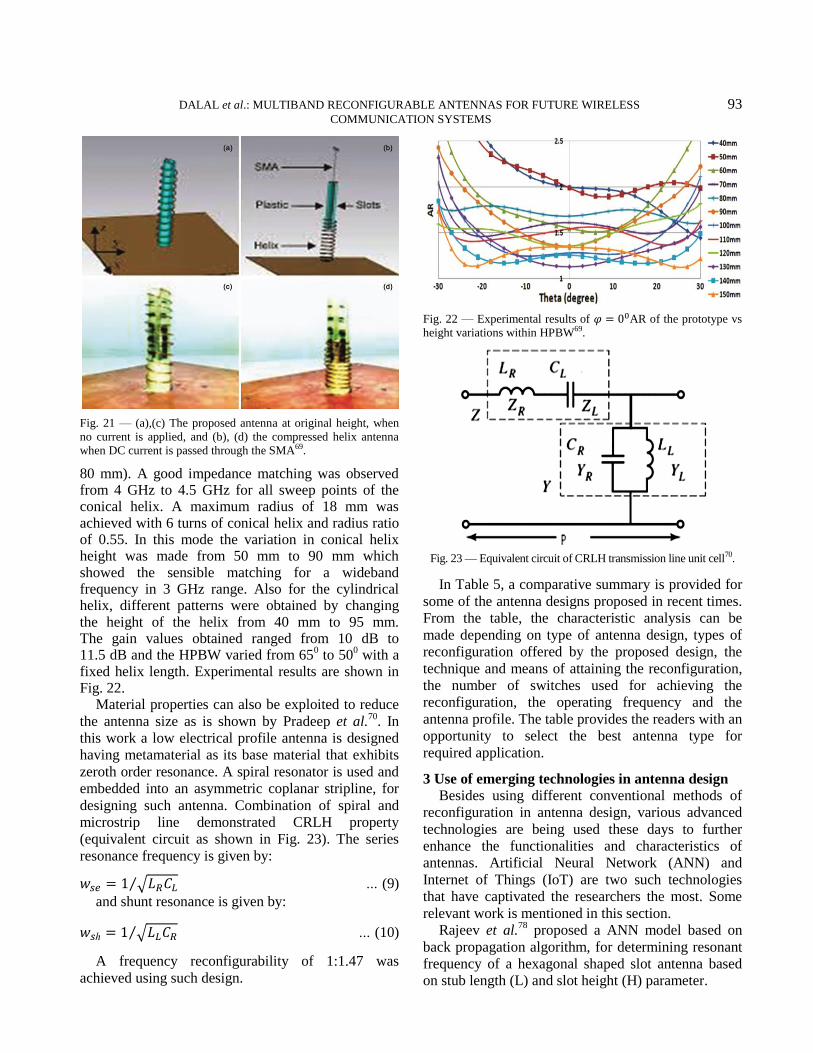
A reconfigurable structure based on smart materials has been presented by Mazlouman et al.
69. The
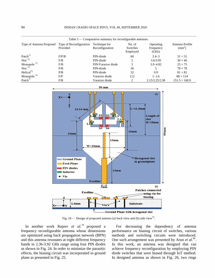
proposed design can be used as an adaptive antenna in various budding communication devices. A helical antenna in axial mode is designed in this work which shows frequency reconfigurability feature by utilizing a shape memory alloy spring actuator for varying antenna height as shown in Fig. 21. As the height of helix is altered, the pitch spacing and pitch angel varies (total length of helix being fixed), resulting in variable radiation patterns. The measured and simulated results have been compared for some helix height of the proposed antenna (60 mm, 70 mm and
Fig. 20 — Reconfigurable antenna using structural alteration67.
DALAL et al.: MULTIBAND RECONFIGURABLE ANTENNAS FOR FUTURE WIRELESS 93 COMMUNICATION SYSTEMS
80 mm). A good impedance matching was observed from 4 GHz to 4.5 GHz for all sweep points of the conical helix. A maximum radius of 18 mm was achieved with 6 turns of conical helix and radius ratio of 0.55. In this mode the variation in conical helix height was made from 50 mm to 90 mm which showed the sensible matching for a wideband frequency in 3 GHz range. Also for the cylindrical helix, different patterns were obtained by changing the height of the helix from 40 mm to 95 mm. The gain values obtained ranged from 10 dB to 11.5 dB and the HPBW varied from 65
0 to 50
0 with a
fixed helix length. Experimental results are shown in Fig. 22.
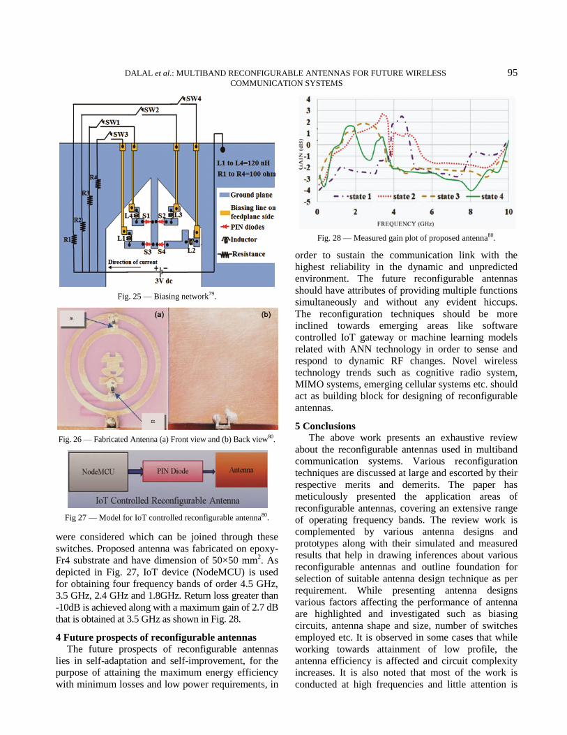
Material properties can also be exploited to reduce
the antenna size as is shown by Pradeep et al.70
. In
this work a low electrical profile antenna is designed
having metamaterial as its base material that exhibits
zeroth order resonance. A spiral resonator is used and
embedded into an asymmetric coplanar stripline, for
designing such antenna. Combination of spiral and
microstrip line demonstrated CRLH property
(equivalent circuit as shown in Fig. 23). The series
resonance frequency is given by:
… (9)
and shunt resonance is given by:
… (10)
A frequency reconfigurability of 1:1.47 was
achieved using such design.
In Table 5, a comparative summary is provided for
some of the antenna designs proposed in recent times.
From the table, the characteristic analysis can be
made depending on type of antenna design, types of
reconfiguration offered by the proposed design, the
technique and means of attaining the reconfiguration,
the number of switches used for achieving the
reconfiguration, the operating frequency and the
antenna profile. The table provides the readers with an
opportunity to select the best antenna type for
required application.
3 Use of emerging technologies in antenna design
Besides using different conventional methods of
reconfiguration in antenna design, various advanced
technologies are being used these days to further
enhance the functionalities and characteristics of
antennas. Artificial Neural Network (ANN) and
Internet of Things (IoT) are two such technologies
that have captivated the researchers the most. Some
relevant work is mentioned in this section.
Rajeev et al.78
proposed a ANN model based on
back propagation algorithm, for determining resonant
frequency of a hexagonal shaped slot antenna based
on stub length (L) and slot height (H) parameter.
Fig. 21 — (a),(c) The proposed antenna at original height, when
no current is applied, and (b), (d) the compressed helix antenna
when DC current is passed through the SMA69.
Fig. 22 — Experimental results of AR of the prototype vs
height variations within HPBW69.
Fig. 23 — Equivalent circuit of CRLH transmission line unit cell70.
94 INDIAN J RADIO SPACE PHYS, VOL 49, SEPTEMBER 2020
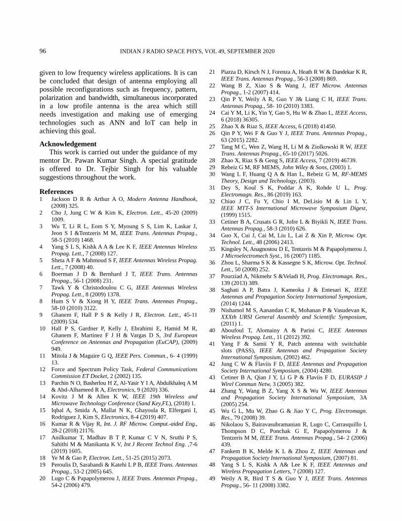
In another work Rajeev et al.79
proposed a
frequency reconfigurable antenna whose dimensions
are optimized using back propagation network (BPN)
and this antenna resonates at eight different frequency
bands in 2.36-3.92 GHz range using four PIN diodes
as shown in Fig. 24. In order to minimize the parasitic
effects, the biasing circuit was incorporated in ground
plane as presented in Fig. 25.
For decreasing the dependency of antenna
performance on biasing circuit of switches, various
methods and switching circuits were introduced.
One such arrangement was presented by Arun et al.80
.
In this work, an antenna was designed that can
achieve frequency reconfiguration by employing PIN
diode switches that were biased through IoT method.
In designed antenna as shown in Fig. 26, two rings
Table 5 — Comparative summary for reconfigurable antennas.
Type of Antenna Proposed Type of Reconfiguration
Provided
Technique for
Reconfiguration
No. of
Switches
Employed
Operating
Frequency
(GHz)
Antenna Profile
(mm2)
Patch71 F/P/R PIN-diode 60 2.4–3 31 × 31
Slot 72 F/R PIN-diode 2 3.6/3.95 30 × 40
Monopole 73 F/B PIN/Varactor diode 3 3.9–4.82 25 × 75 Slot 74 P/R PIN-diode 36 5 78 × 78
Helical75 P/R PIN-diode 32 0.9 81 × 81
Monopole 76 F/P Varactor diode 112 1–1.6 88 × 114
Patch77 F/R Varactor diode 2 2.15/2.25/2.38 151.5 × 160.9
Fig. 24 — Design of proposed antenna (a) back view and (b) side view79.
DALAL et al.: MULTIBAND RECONFIGURABLE ANTENNAS FOR FUTURE WIRELESS 95 COMMUNICATION SYSTEMS
were considered which can be joined through these
switches. Proposed antenna was fabricated on epoxy-
Fr4 substrate and have dimension of 50×50 mm2. As
depicted in Fig. 27, IoT device (NodeMCU) is used
for obtaining four frequency bands of order 4.5 GHz,
3.5 GHz, 2.4 GHz and 1.8GHz. Return loss greater than
-10dB is achieved along with a maximum gain of 2.7 dB
that is obtained at 3.5 GHz as shown in Fig. 28.
4 Future prospects of reconfigurable antennas
The future prospects of reconfigurable antennas
lies in self-adaptation and self-improvement, for the
purpose of attaining the maximum energy efficiency
with minimum losses and low power requirements, in
order to sustain the communication link with the
highest reliability in the dynamic and unpredicted
environment. The future reconfigurable antennas
should have attributes of providing multiple functions
simultaneously and without any evident hiccups.
The reconfiguration techniques should be more
inclined towards emerging areas like software
controlled IoT gateway or machine learning models
related with ANN technology in order to sense and
respond to dynamic RF changes. Novel wireless
technology trends such as cognitive radio system,
MIMO systems, emerging cellular systems etc. should
act as building block for designing of reconfigurable
antennas.
5 Conclusions
The above work presents an exhaustive review
about the reconfigurable antennas used in multiband
communication systems. Various reconfiguration
techniques are discussed at large and escorted by their
respective merits and demerits. The paper has
meticulously presented the application areas of
reconfigurable antennas, covering an extensive range
of operating frequency bands. The review work is
complemented by various antenna designs and
prototypes along with their simulated and measured
results that help in drawing inferences about various
reconfigurable antennas and outline foundation for
selection of suitable antenna design technique as per
requirement. While presenting antenna designs
various factors affecting the performance of antenna
are highlighted and investigated such as biasing
circuits, antenna shape and size, number of switches
employed etc. It is observed in some cases that while
working towards attainment of low profile, the
antenna efficiency is affected and circuit complexity
increases. It is also noted that most of the work is
conducted at high frequencies and little attention is
Fig. 25 — Biasing network79.
Fig. 26 — Fabricated Antenna (a) Front view and (b) Back view80.
Fig 27 — Model for IoT controlled reconfigurable antenna80.
Fig. 28 — Measured gain plot of proposed antenna80.
96 INDIAN J RADIO SPACE PHYS, VOL 49, SEPTEMBER 2020
given to low frequency wireless applications. It is can
be concluded that design of antenna employing all
possible reconfigurations such as frequency, pattern,
polarization and bandwidth, simultaneous incorporated
in a low profile antenna is the area which still
needs investigation and making use of emerging
technologies such as ANN and IoT can help in
achieving this goal.
Acknowledgement This work is carried out under the guidance of my
mentor Dr. Pawan Kumar Singh. A special gratitude
is offered to Dr. Tejbir Singh for his valuable
suggestions throughout the work.
References 1 Jackson D R & Arthur A O, Modern Antenna Handbook,
(2008) 325.
2 Cho J, Jung C W & Kim K, Electron. Lett., 45-20 (2009)
1009.
3 Wu T, Li R L, Eom S Y, Myoung S S, Lim K, Laskar J,
Jeon S I &Tentzeris M M, IEEE Trans. Antennas Propag.,
58-5 (2010) 1468.
4 Yang S L S, Kishk A A & Lee K F, IEEE Antennas Wireless
Propag. Lett., 7 (2008) 127.
5 Sheta A F & Mahmoud S F, IEEE Antennas Wireless Propag.
Lett., 7 (2008) 40.
6 Boerman J D & Bernhard J T, IEEE Trans. Antennas
Propag., 56-1 (2008) 231.
7 Tawk Y & Christodoulou C G, IEEE Antennas Wireless
Propag. Lett., 8 (2009) 1378.
8 Hum S V & Xiong H Y, IEEE Trans. Antennas Propag.,
58-10 (2010) 3122.
9 Ghanem F, Hall P S & Kelly J R, Electron. Lett., 45-11
(2009) 534.
10 Hall P S, Gardner P, Kelly J, Ebrahimi E, Hamid M R,
Ghanem F, Martinez F J H & Vargas D S, 3rd European
Conference on Antennas and Propagation (EuCAP), (2009)
949.
11 Mitola J & Maguire G Q, IEEE Pers. Commun., 6- 4 (1999)
13.
12 Force and Spectrum Policy Task, Federal Communications
Commission ET Docket, 2 (2002) 135.
13 Parchin N O, Basherlou H Z, Al-Yasir Y I A, Abdulkhaleq A M
& Abd-Alhameed R A, Electronics, 9 (2020) 336.
14 Kovitz J M & Allen K W, IEEE 19th Wireless and
Microwave Technology Conference (Sand Key,FL), (2018) 1.
15 Iqbal A, Smida A, Mallat N K, Ghayoula R, Elfergani I,
Rodriguez J, Kim S, Electronics, 8-4 (2019) 407.
16 Kumar R & Vijay R, Int. J. RF Microw. Comput.-aided Eng.,
28-2 (2018) 21176.
17 Anilkumar T, Madhav B T P, Kumar C V N, Sruthi P S,
Sahithi M & Manikanta K V, Int J Recent Technol Eng. ,7-6
(2019) 1605.
18 Ye M & Gao P, Electron. Lett., 51-25 (2015) 2073.
19 Peroulis D, Sarabandi & Katehi L P B, IEEE Trans. Antennas
Propag., 53-2 (2005) 645.
20 Lugo C & Papapolymerou J, IEEE Trans. Antennas Propag.,
54-2 (2006) 479.
21 Piazza D, Kirsch N J, Forenza A, Heath R W & Dandekar K R,
IEEE Trans. Antennas Propag., 56-3 (2008) 869.
22 Wang B Z, Xiao S & Wang J, IET Microw. Antennas
Propag., 1-2 (2007) 414.
23 Qin P Y, Weily A R, Guo Y J& Liang C H, IEEE Trans.
Antennas Propag., 58- 10 (2010) 3383.
24 Cai Y M, Li K, Yin Y, Gao S, Hu W & Zhao L, IEEE Access,
6 (2018) 36305.
25 Zhao X & Riaz S, IEEE Access, 6 (2018) 41450.
26 Qin P Y, Wei F & Guo Y J, IEEE Trans. Antennas Propag.,
63 (2015) 2282.
27 Tang M C, Wen Z, Wang H, Li M & Ziolkowski R W, IEEE
Trans. Antennas Propag., 65-10 (2017) 5026.
28 Zhao X, Riaz S & Geng S, IEEE Access, 7 (2019) 46739.
29 Rebeiz G M, RF MEMS, John Wiley & Sons, (2003) 1.
30 Wang L F, Huang Q A & Han L, Rebeiz G M, RF-MEMS
Theory, Design and Technology, (2003).
31 Dey S, Koul S K, Poddar A K, Rohde U L, Prog.
Electromagn. Res., 86 (2019) 163.
32 Chiao J C, Fu Y, Chio I M, DeLisio M & Lin L Y,
IEEE MTT-S International Microwave Symposium Digest,
(1999) 1515.
33 Cetiner B A, Crusats G R, Jofre L & Biyikli N, IEEE Trans.
Antennas Propag., 58-3 (2010) 626.
34 Guo X, Cui J, Cai M, Liu L, Lai Z & Xin P, Microw. Opt.
Technol. Lett., 48 (2006) 2413.
35 Kingsley N, Anagnostou D E, Tentzeris M & Papapolymerou J,
J Microelectromech Syst., 16 (2007) 1185.
36 Zhou L, Sharma S K & Kassegne S K, Microw. Opt. Technol.
Lett., 50 (2008) 252.
37 Pourziad A, Nikmehr S &Veladi H, Prog. Electromagn. Res.,
139 (2013) 389.
38 Saghati A P, Batra J, Kameoka J & Entesari K, IEEE
Antennas and Propagation Society International Symposium,
(2014) 1244. 39 Nishamol M S, Aanandan C K, Mohanan P & Vasudevan K,
XXXth URSI General Assembly and Scientific Symposium, (2011) 1.
40 Aboufoul T, Alomainy A & Parini C, IEEE Antennas Wireless Propag. Lett., 11 (2012) 392.
41 Yang F & Samii Y R, Patch antenna with switchable slots (PASS), IEEE Antennas and Propagation Society International Symposium, (2002) 462.
42 Jung C W & Flaviis F D, IEEE Antennas and Propagation Society International Symposium, (2004) 4280.
43 Cetiner B A, Qian J Y, Li G P & Flaviis F D, EURASIP J Wirel Commun Netw, 3 (2005) 382.
44 Zhang Y, Wang B Z, Yang X S & Wu W, IEEE Antennas and Propagation Society International Symposium, 3A (2005) 254.
45 Wu G L, Mu W, Zhao G & Jiao Y C, Prog. Electromagn. Res., 79 (2008) 39.
46 Nikolaou S, Bairavasubramanian R, Lugo C, Carrasquillo I, Thompson D C, Ponchak G E, Papapolymerou J & Tentzeris M M, IEEE Trans. Antennas Propag., 54- 2 (2006) 439.
47 Fankem B K, Melde K L & Zhou Z, IEEE Antennas and Propagation Society International Symposium, (2007) 81.
48 Yang S L S, Kishk A A& Lee K F, IEEE Antennas and Wireless Propagation Letters, 7 (2008) 127.
49 Weily A R, Bird T S & Guo Y J, IEEE Trans. Antennas
Propag., 56- 11 (2008) 3382.
DALAL et al.: MULTIBAND RECONFIGURABLE ANTENNAS FOR FUTURE WIRELESS 97 COMMUNICATION SYSTEMS
50 Perruisseau-Carrier J, Pardo-Carrera P & Miskovsky P, IEEE
Trans. Antennas Propag., 58-7 (2010) 2218.
51 Artiga X, Perruisseau-Carrier J, Pardo-Carrera P, Llamas-
Garro I & Brito-Brito Z, IEEE Antennas Wireless Propag.
Lett., 10 (2011) 56.
52 Sanchez-Escuderos D, Ferrando-Bataller M, Baquero-
Escudero M & Herranz J I, IEEE Antennas Wireless Propag.
Lett., 10 (2011) 721.
53 Abutarboush H F, Nilavalan R, Cheung S W, Nasr K M,
Peter T, Budimir D & Al-Raweshidy H, IEEE Trans.
Antennas Propag., 60- 1 (2012) 36.
54 Majid H A, Kamal M , Rahim A, Hamid M R & Ismail M F,
IEEE Antennas Wireless Propag. Lett., 11 (2012) 616.
55 Cai Y, Guo Y J & Bird T S, IEEE Trans. Antennas Propag.,
60- 6 (2012) 2905.
56 Nguyen-Trong N, Hall L & Fumeaux C, IEEE Trans.
Antennas Propag., 63-11 (2015) 5235.
57 Wu T, Li R L, Eom S Y, Myoung S S, Lim K, Laskar J,
Jeon S I & Tentzeris M M, IEEE Trans. Antennas Propag.,
58- 5 (2010) 1468.
58 Fengrong L & Ting W, IEEE International Conference on
Microwave and Millimeter Wave Technology (2016) 740.
59 Mak K M, Lai H W, Luk K M &Ho K L, IEEE Trans.
Antennas Propag., 65-3 (2017) 1388.
60 Al-Husseini M, Tawk Y, Christodoulou C G, Kabalan K Y &
Hajj A E, In Antennas and Propagation Society International
Symposium, (2010) 1.
61 Rajeshkumar V & Raghavan S, Int J Electron Commun,
69- 1 (2015) 274.
62 Kumar J, Talukdar F A &Basu B, Microw. Opt. Technol.
Lett., 58- 9 (2016) 2214.
63 Zheng S H, Liu X Y & Tentzeris M M, In Proceedings of the
IEEE Antennas and Propagation Society International
Symposium, (2014) 1246.
64 Li Z, Rodrigo D, Jofre L & Cetiner B A, IEEE Trans. Antennas Propag., 61- 4 (2013) 1947.
65 Tawk Y, Costantine J, Avery K & Christodoulou C G, IEEE Trans. Antennas Propag., 59- 5 (2011) 1773.
66 Zheng S H, Liu X Y & Tentzeris M M, IEEE Antennas and Propagation Society International Symposium, (2014) 1246.
67 Tawk Y, Costantine J, Ayoub F, Christodoulou C, Doyle D & Lane S A, IEEE International Symposium on Antennas and Propagation & USNC/URSI National Radio Science Meeting, (2017) 419.
68 Mazlouman S J, Mahanfar A, Menon C & Vaughan R G, IEEE Trans. Antennas Propag., 59- 4 (2011) 1070.
69 Pradeep A, Mridula S & Mohanan P, EJAET, 12 (2015) 68. 70 Rodrigo D, Cetiner B A & Jofre L, Frequency, IEEE Trans.
Antennas Propag., 62 (2014) 3422. 71 Han L, Wang C, Zhang W, Ma R & Zeng Q, Int J Antennas
Propag, 62-6 ( 2018) 1. 72 Kingsly S, Thangarasu D, Kanagasabai M, Alsath M G,
Thipparaju R R, Palaniswamy S K, Sambandam P, IEEE Antennas Wirel. Propag. Lett., 17 (2018) 1416.
73 Chen A, Ning X, Wang L & Zhang Z, IEEE Asia Pacific Microwave Conference, (2017) 108.
74 Yi X, Huitema L & Wong H, IEEE Trans. Antennas Propag., 66 (2018) 2707.
75 Liang B, Sanz-Izquierdo B, Parker E A & Batchelor J C, IEEE Trans. Antennas Propag., 63 (2015) 33.
76 Zainarry S N M, Nguyen-Trong N &Fumeaux C, IEEE Antennas Wirel. Propag. Lett., 17 (2018) 617.
77 Kumar R, Kumar P & Vijay R, Mikrotalasna revija, 17-4 (2019) 27.
78 Kumar R, Kumar P, Singh S & Vijay R, Int J Electron Commun, 112 (2019) 152962
79 Arun V & Marx L R K, Def. Sci. J., 68-6 (2018) 566. 80 Arun V & Marx L R K, Internet of Things Controlled
Reconfigurable Antenna for RF Harvesting, Def. Sci. J., 68-6 (2018) 566.


![A RECONFIGURABLE U-KOCH MICROSTRIP ANTENNA FOR … · geometries, and that Koch fractal antennas are multiband structures. The authors of [10] related multiple resonant frequencies](https://img.pdfslide.net/doc/110x75/5e764ec1b5799e0f2317c4ff/a-reconfigurable-u-koch-microstrip-antenna-for-geometries-and-that-koch-fractal.jpg)