Embed Size (px)
Citation preview
28 B. GUENAD, S. M. MERIAH, F. T. BENDIMERAD, MULTIBEAM ANTENNAS ARRAY PATTERN SYNTHESIS…
Multibeam Antennas Array Pattern Synthesis Using a Variational Method
Boumediene GUENAD, Sidi Mohamed MERIAH, Fethi Tarik BENDIMERAD
Telecommunications Laboratory, Electronics Dept., Faculty of Engineering, Abou-Bekr Belkaïd University – Tlemcen, P. O. Box 230, Chetouane, 13000 Tlemcen, Algeria
Abstract. In this paper a new method is described for multibeam antennas synthesis where both the amplitude and phase of each radiating element is a design variable. The developed optimization method made possible to solve the synthesis problem and to answer all the constraints imposed by the radiation pattern. Two approaches for visualizing satellite antenna radiation patterns are pre-sented. Gain-level contours drawn over a geographical map gives clearest qualitative information. A three-dimen-sional (3D) surface plot displays the qualitative shape of the radiation pattern more naturally. The simulations re-sults have shown power, precision and speed of the varia-tional method with respect to the constraints imposed on radiation pattern of the of multibeam antennas network.
Keywords Multibeam antennas, optimization, radiation pattern synthesis, variational method.
1. Introduction Multiple-beam antennas are currently being used for
direct-broadcast satellites (DBS), personal communication satellites (PCS), military communication satellites, and high-speed Internet applications [1], [2]. These antennas provide mostly contiguous coverage over a specified field of view on Earth by using high-gain multiple spot beams for downlink (satellite-to-ground) and uplink (ground-to-satellite) coverage. The design objectives for the multiple- beam antennas are to maximize the minimum gain over the coverage region, and to maximize the pattern roll-off out-side the spot-beam area and to minimize the sidelobe ra-diation in order to maximize the frequency reuse. A num-ber of design methodologies for multiple-pattern arrays have been described in the literature [3], [4], and [5]. In the present work, we try to find the best excitations coeffi-cients using the variational method, in order to minimize the sidelobes levels and respecting the pattern shape.
2. Multiple Beam Antenna Design Because several spot beams have to be created
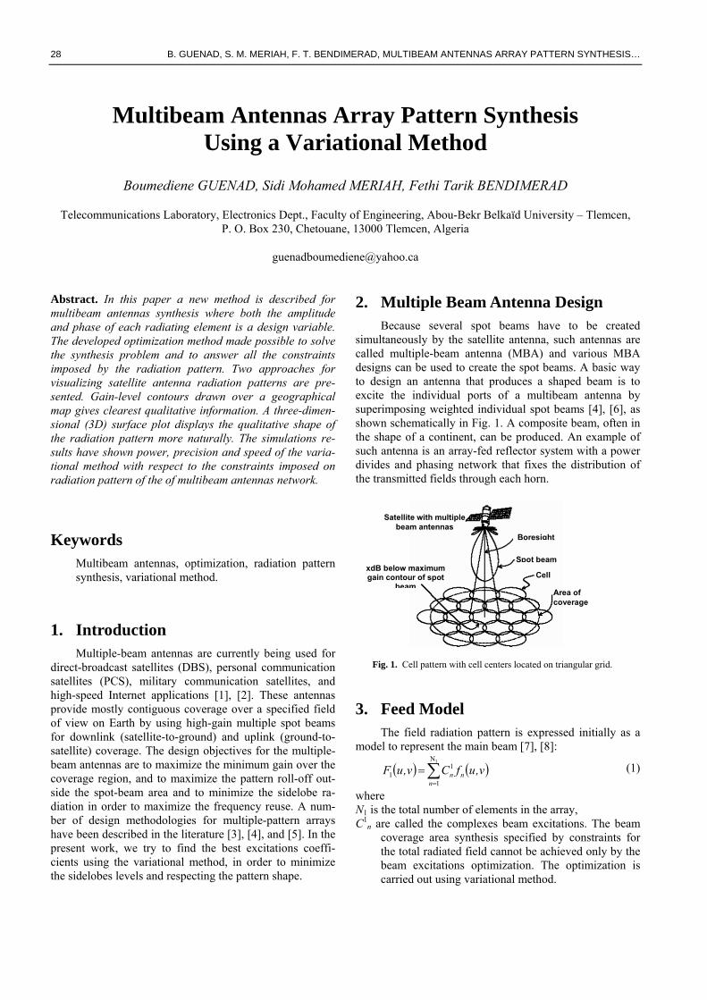
simultaneously by the satellite antenna, such antennas are called multiple-beam antenna (MBA) and various MBA designs can be used to create the spot beams. A basic way to design an antenna that produces a shaped beam is to excite the individual ports of a multibeam antenna by superimposing weighted individual spot beams [4], [6], as shown schematically in Fig. 1. A composite beam, often in the shape of a continent, can be produced. An example of such antenna is an array-fed reflector system with a power divides and phasing network that fixes the distribution of the transmitted fields through each horn.
Satellite with multiple
beam antennas Boresight
Spot beam xdB below maximumgain contour of spot
beamCell
Area of coverage
Fig. 1. Cell pattern with cell centers located on triangular grid.
3. Feed Model The field radiation pattern is expressed initially as a
model to represent the main beam [7], [8]:
( ) ( )∑=
=1N
1
11
nnn v,ufCv,uF (1)
where N1 is the total number of elements in the array, C1
n are called the complexes beam excitations. The beam coverage area synthesis specified by constraints for the total radiated field cannot be achieved only by the beam excitations optimization. The optimization is carried out using variational method.
RADIOENGINEERING, VOL. 16, NO. 2, JUNE 2007 29
(u,v) space coordinates are defined according to
( ) ( )( ) ( )⎩
⎨⎧
==
φθφθ
sinsincossin
vu (2)
which are often used to display 2-dimensional radiation patterns. Accordingly it holds, θ=arcsin[√(u2+v2)], φ=arctan(v/u), further note that for real θ≤π/2 must hold u2+v2≤1.
fn The far field radiation pattern of single aperture multiple-beam antennas using the “basic-feed concept”, and is given by:
( ) ( ) ( ) ( )⎥⎦
⎤⎢⎣
⎡
ηη
−+ηη
+= 2
20
10
0
121
4
n
n
n
nn
JeJee
v,uf (3)
where
( ) ( )22nnn vvuuD
−+−λπ
=η (4)
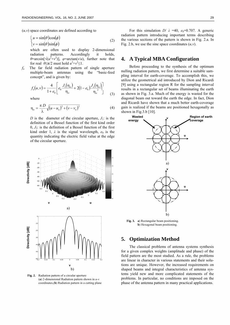
D is the diameter of the circular aperture, J1: is the definition of a Bessel function of the first kind order 0, J2: is the definition of a Bessel function of the first kind order 1, λ is the signal wavelength, e0 is the quantity indicating the electric field value at the edge of the circular aperture.
-0.2-0.1
00.1
0.2
-0.2-0.1
00.1
0.2
-60
-50
-40
-30
-20
-10
0
-60
-50
-40
-30
-20
-10
0
a)
-0.2 -0.15 -0.1 -0.05 0 0.05 0.1 0.15 0.2-60
-50
-40
-30
-20
-10
0
b)
Fig. 2. Radiation pattern of a circular aperture (a) 2-dimensional Radiation pattern shown in u-v coordinates,(b) Radiation pattern in a cutting plane
For this simulation D/ λ =40, e0=0.707. A generic radiation pattern introducing important terms describing the various sections of the pattern is shown in Fig. 2.a. In Fig. 2.b, we use the sine space coordinates (u,v).
4. A Typical MBA Configuration Before proceeding to the synthesis of the optimum
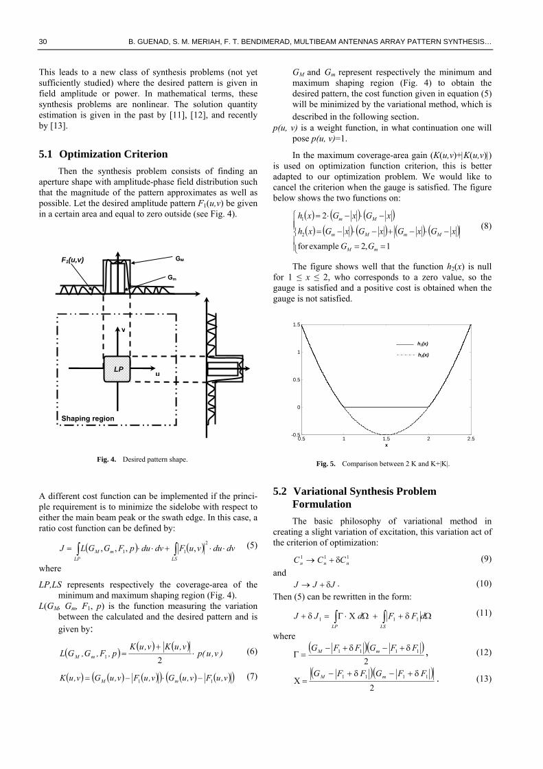
nulling radiation pattern, we first determine a suitable sam-pling interval for earth-coverage. To accomplish this, we utilize the geometrical aid introduced by Dion and Ricardi [9] using a rectangular region R for the sampling interval results in a rectangular set of beams illuminating the earth as shown in Fig. 3.a. Much of the energy is wasted for the diagonal beam out toward the earth the edge. In fact, Dion and Ricardi have shown that a much better earth-coverage gain is realized if the beams are positioned hexagonally as shown in Fig.3.b [10].
a)
b)
Fig. 3. a) Rectangular beam positioning. b) Hexagonal beam positioning.
5. Optimization Method The classical problems of antenna systems synthesis
for a given complex weights (amplitude and phase) of the field pattern are the most studied. As a rule, the problems are linear in character in various statements and their solu-tions are unique. However, the increased requirements on shaped beams and integral characteristics of antenna sys-tems yield new and more complicated statements of the problems. In particular, no conditions are imposed on the phase of the antenna pattern in many practical applications.
Dire
ctiv
ity [d
B]
Dire
ctiv
ity [d
B]
u v
v
Region of earth coverage
Wasted energy
v
v
u
u
30 B. GUENAD, S. M. MERIAH, F. T. BENDIMERAD, MULTIBEAM ANTENNAS ARRAY PATTERN SYNTHESIS…
This leads to a new class of synthesis problems (not yet sufficiently studied) where the desired pattern is given in field amplitude or power. In mathematical terms, these synthesis problems are nonlinear. The solution quantity estimation is given in the past by [11], [12], and recently by [13].
5.1 Optimization Criterion Then the synthesis problem consists of finding an
aperture shape with amplitude-phase field distribution such that the magnitude of the pattern approximates as well as possible. Let the desired amplitude pattern F1(u,v) be given in a certain area and equal to zero outside (see Fig. 4).
A different cost function can be implemented if the princi-ple requirement is to minimize the sidelobe with respect to either the main beam peak or the swath edge. In this case, a ratio cost function can be defined by:
( ) ( ) dvduvuFdvdupFGGLJLP LS
mM ⋅⋅+⋅⋅= ∫ ∫2
11 ,,,, (5)
where
LP,LS represents respectively the coverage-area of the minimum and maximum shaping region (Fig. 4).
L(GM, Gm, F1, p) is the function measuring the variation between the calculated and the desired pattern and is given by:
( ) ( ) ( ))v,u(p
v,uKv,uKp,F,G,GL mM ⋅
+=
21 (6)
( ) ( ) ( )( ) ( ) ( )( )v,uFv,uGv,uFv,uGv,uK mM 11 −⋅−= (7)
GM and Gm represent respectively the minimum and maximum shaping region (Fig. 4) to obtain the desired pattern, the cost function given in equation (5) will be minimized by the variational method, which is described in the following section.
p(u, v) is a weight function, in what continuation one will pose p(u, v)=1.
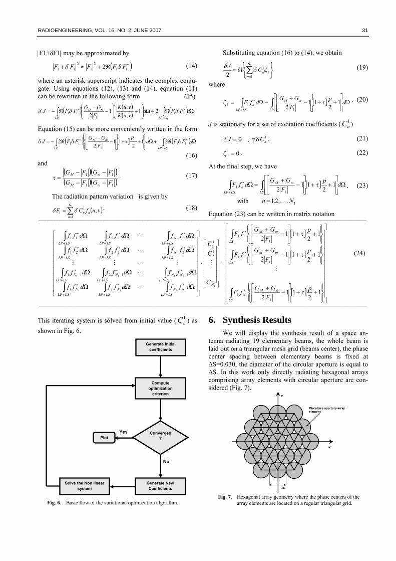
In the maximum coverage-area gain (K(u,v)+|K(u,v)|) is used on optimization function criterion, this is better adapted to our optimization problem. We would like to cancel the criterion when the gauge is satisfied. The figure below shows the two functions on:
( ) ( ) ( )( ) ( ) ( ) ( ) ( )
⎪⎪⎩
⎪⎪⎨
⎧
==
−⋅−+−⋅−=
−⋅−⋅=
1,2 examplefor
2
2
1
mM
MmMm
Mm
GG
xGxGxGxGxh
xGxGxh (8)
The figure shows well that the function h2(x) is null for 1 ≤ x ≤ 2, who corresponds to a zero value, so the gauge is satisfied and a positive cost is obtained when the gauge is not satisfied.
0.5 1 1.5 2 2.5-0.5
0
0.5
1
1.5
h1(x)
h2(x)
x
Fig. 5. Comparison between 2 K and K+|K|.
5.2 Variational Synthesis Problem Formulation The basic philosophy of variational method in
creating a slight variation of excitation, this variation act of the criterion of optimization:
111nnn CCC δ+→ (9)
and JJJ δ+→ . (10)
Then (5) can be rewritten in the form:
Ωδ++ΩΧ⋅Γ=δ+ ∫∫ dFF dJJLSLP
111 (11)
where ( )( )
21111 FFGFFG mM δ+−δ+−
=Γ , (12)
( )( )2
1111 FFGFFG mM δ+−δ+−=Χ . (13)
u
v
Gm
F1(u,v)
Shaping region
LP
GM
Fig. 4. Desired pattern shape.
RADIOENGINEERING, VOL. 16, NO. 2, JUNE 2007 31
|F1+δF1| may be approximated by
( )∗ℜ+≈+ 112
12
11 2 FFFFF δδ (14)
where an asterisk superscript indicates the complex conju-gate. Using equations (12), (13) and (14), equation (11) can be rewritten in the following form (15)
( ) ( )( ) ( ) Ωℜ+Ω⎟⎟
⎠
⎞⎜⎜⎝
⎛+⎟
⎟⎠
⎞⎜⎜⎝
⎛−
−ℜ−= ∫∫
+
∗∗ dFFdvuKvuK
FGGFFJ
LSLP
mM
LP11
111 21
,,
12
δδδ .
Equation (15) can be more conveniently written in the form
( ) [ ] ( ) Ωδℜ+Ω⎪⎭
⎪⎬⎫
⎪⎩
⎪⎨⎧
+τ+⎥⎥⎦
⎤
⎢⎢⎣
⎡−
−δℜ−=δ ∫∫
+
∗∗ dFFdp
FGG
FFJLSLP
mM
LP11
111 21
211
22
(16) and
( )( )( )( )11
11
FGFGFGFG
mM
mM
−−
−−=τ . (17)
The radiation pattern variation is given by
( )∑=
=1N
1
11 ,
nnn vufCF δδ . (18)
Substituting equation (16) to (14), we obtain
⎭⎬⎫
⎩⎨⎧
ℜ= ∑=
1N
11
1
2 nnCJ ζδδ (19)
where
[ ] Ω⎥⎥⎦
⎤
⎢⎢⎣
⎡+τ+
⎥⎥⎦
⎤
⎢⎢⎣
⎡−
+−Ω=ζ ∫∫
+
∗ dpF
GGdfF
LP
mM
LSLPn 1
211
2 111
. (20)
J is stationary for a set of excitation coefficients ( 1nC )
10 nC;J δ∀=δ , (21)
01 =ζ . (22)
At the final step, we have
[ ]
1
11
21with
12
112
N,,,n
dpF
GGdfF
LS
mM
LSLPn
K=
Ω⎥⎥⎦
⎤
⎢⎢⎣
⎡+τ+
⎥⎥⎦
⎤
⎢⎢⎣
⎡−
+=Ω ∫∫
+
∗ . (23)
Equation (23) can be written in matrix notation -========================================================================================================================================================================================================================
[ ]
[ ]
[ ] ⎥⎥⎥⎥⎥⎥⎥⎥⎥⎥⎥
⎦
⎤
⎢⎢⎢⎢⎢⎢⎢⎢⎢⎢⎢
⎣
⎡
⎪⎭
⎪⎬⎫
⎪⎩
⎪⎨⎧
+τ+⎥⎥⎦
⎤
⎢⎢⎣
⎡−
+
⎪⎭
⎪⎬⎫
⎪⎩
⎪⎨⎧
+τ+⎥⎥⎦
⎤
⎢⎢⎣
⎡−
+
⎪⎭
⎪⎬⎫
⎪⎩
⎪⎨⎧
+τ+⎥⎥⎦
⎤
⎢⎢⎣
⎡−
+
=
⎥⎥⎥⎥⎥⎥
⎦
⎤
⎢⎢⎢⎢⎢⎢
⎣
⎡
⋅
⎥⎥⎥⎥⎥⎥⎥⎥⎥
⎦
⎤
⎢⎢⎢⎢⎢⎢⎢⎢⎢
⎣
⎡
ΩΩΩ
ΩΩΩ
ΩΩΩ
ΩΩΩ
∫
∫
∫
∫∫∫∫∫∫
∫∫∫∫∫∫
∗
∗
∗
+
∗
+
∗
+
∗+
∗−
+
∗−
+
∗−
+
∗
+
∗
+
∗+
∗
+
∗
+
∗
LS
mMN
LS
mM
LS
mM
N
LSLPNN
LSLPN
LSLPN
LSLPNN
LSLPN
LSLPN
LSLPN
LSLPLSLP
LSLPN
LSLPLSLP
pF
GGfF
pF
GGfF
pF
GGfF
C
CC
dffdffdff
dffdffdff
dffdffdff
dffdffdff
12
112
12
112
12
112
11
121
111
1
12
11
21
11211
22221
11211
1
1
1111
1111
1
1
MM
L
L
MLMM
L
L
(24)
===========================================================================================================================================================================================================================
This iterating system is solved from initial value ( 1nC ) as
shown in Fig. 6.
Compute optimization
criterion
Generate Initial coefficients
Converged? Plot
Generate New Coefficients
Solve the Non linear system
No
Yes
Fig. 6. Basic flow of the variational optimization algorithm.
6. Synthesis Results We will display the synthesis result of a space an-
tenna radiating 19 elementary beams, the whole beam is laid out on a triangular mesh grid (beams center), the phase center spacing between elementary beams is fixed at ∆S=0.030, the diameter of the circular aperture is equal to ∆S. In this work only directly radiating hexagonal arrays comprising array elements with circular aperture are con-sidered (Fig. 7).
Circulaire aperture element
∆S
array
u
v
Fig. 7. Hexagonal array geometry where the phase centers of the
array elements are located on a regular triangular grid.
32 B. GUENAD, S. M. MERIAH, F. T. BENDIMERAD, MULTIBEAM ANTENNAS ARRAY PATTERN SYNTHESIS…
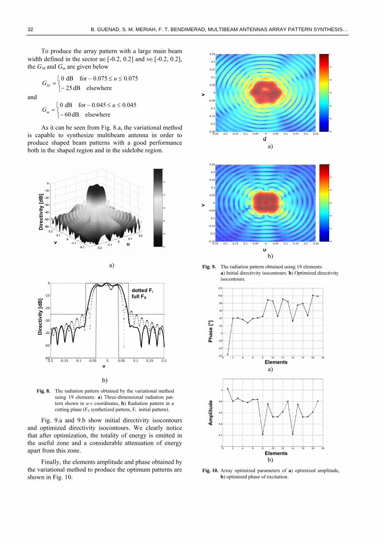
To produce the array pattern with a large main beam width defined in the sector u∈[-0.2, 0.2] and v∈[-0.2, 0.2], the GM and Gm are given below
⎩⎨⎧−
≤≤−=
elsewheredB25075.0075.0fordB0 u
GM
and
⎩⎨⎧−
≤≤−=
elsewheredB60045.0045.0fordB0 u
Gm
As it can be seen from Fig. 8.a, the variational method is capable to synthesize multibeam antenna in order to produce shaped beam patterns with a good performance both in the shaped region and in the sidelobe region.
a)
-0.2 -0.15 -0.1 -0.05 0 0.05 0.1 0.15 0.2-60
-50
-40
-30
-20
-10
0
b) Fig. 8. The radiation pattern obtained by the variational method
using 19 elements: a) Three-dimensional radiation pat-tern shown in u-v coordinates, b) Radiation pattern in a cutting plane (FS synthetized pattern, Fi initial pattern).
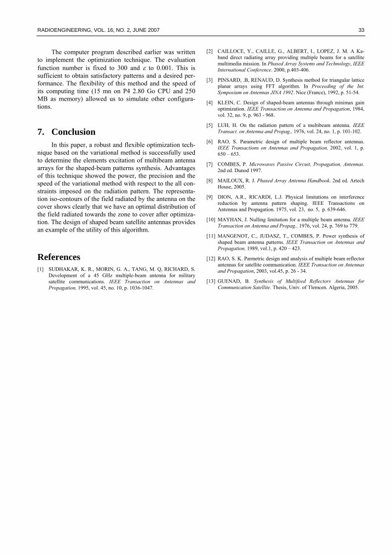
Fig. 9.a and 9.b show initial directivity isocontours and optimized directivity isocontours. We clearly notice that after optimization, the totality of energy is emitted in the useful zone and a considerable attenuation of energy apart from this zone.
Finally, the elements amplitude and phase obtained by the variational method to produce the optimum patterns are shown in Fig. 10.
-0.25 -0.2 -0.15 -0.1 -0.05 0 0.05 0.1 0.15 0.2 0.25-0.25
-0.2
-0.15
-0.1
-0.05
0
0.05
0.1
0.15
0.2
0.25
u
v
-60
-50
-40
-30
-20
-10
0
a)
-0.25 -0.2 -0.15 -0.1 -0.05 0 0.05 0.1 0.15 0.2 0.25-0.25
-0.2
-0.15
-0.1
-0.05
0
0.05
0.1
0.15
0.2
0.25
-60
-50
-40
-30
-20
-10
0
b)
Fig. 9. The radiation pattern obtained using 19 elements: a) Initial directivity isocontours. b) Optimized directivity isocontours.
a)
b)
Fig. 10. Array optimized parameters of a) optimized amplitude, b) optimized phase of excitation.
v
Dire
ctiv
ity [d
B]
u
Dire
ctiv
ity [d
B]
v
dotted Fi full FS
u
u
v v
Elements
Elements
Phas
e [°
] A
mpl
itude
RADIOENGINEERING, VOL. 16, NO. 2, JUNE 2007 33
The computer program described earlier was written to implement the optimization technique. The evaluation function number is fixed to 300 and ε to 0.001. This is sufficient to obtain satisfactory patterns and a desired per-formance. The flexibility of this method and the speed of its computing time (15 mn on P4 2.80 Go CPU and 250 MB as memory) allowed us to simulate other configura-tions.
7. Conclusion In this paper, a robust and flexible optimization tech-
nique based on the variational method is successfully used to determine the elements excitation of multibeam antenna arrays for the shaped-beam patterns synthesis. Advantages of this technique showed the power, the precision and the speed of the variational method with respect to the all con-straints imposed on the radiation pattern. The representa-tion iso-contours of the field radiated by the antenna on the cover shows clearly that we have an optimal distribution of the field radiated towards the zone to cover after optimiza-tion. The design of shaped beam satellite antennas provides an example of the utility of this algorithm.
References [1] SUDHAKAR, K. R., MORIN, G. A., TANG, M. Q, RICHARD, S.
Development of a 45 GHz multiple-beam antenna for military satellite communications. IEEE Transaction on Antennas and Propagation, 1995, vol. 45, no. 10, p. 1036-1047.
[2] CAILLOCE, Y., CAILLE, G., ALBERT, I., LOPEZ, J. M. A Ka-band direct radiating array providing multiple beams for a satellite multimedia mission. In Phased Array Systems and Technology, IEEE International Conference. 2000, p.403-406.
[3] PINSARD, .B, RENAUD, D. Synthesis method for triangular lattice planar arrays using FFT algorithm. In Proceeding of the Int. Symposium on Antennas JINA 1992. Nice (France), 1992, p. 51-54.
[4] KLEIN, C. Design of shaped-beam antennas through minimax gain optimization. IEEE Transaction on Antenna and Propagation, 1984, vol. 32, no. 9, p. 963 - 968.
[5] LUH, H. On the radiation pattern of a multibeam antenna. IEEE Transact. on Antenna and Propag., 1976, vol. 24, no. 1, p. 101-102.
[6] RAO, S. Parametric design of multiple beam reflector antennas. IEEE Transactions on Antennas and Propagation, 2002, vol. 1, p. 650 – 653.
[7] COMBES, P. Microwaves Passive Circuit, Propagation, Antennas. 2nd ed. Dunod 1997.
[8] MAILOUX, R. J. Phased Array Antenna Handbook. 2nd ed. Artech House, 2005.
[9] DION, A.R., RICARDI, L.J. Physical limitations on interference reduction by antenna pattern shaping. IEEE Transactions on Antennas and Propagation. 1975, vol. 23, no. 5, p. 639-646.
[10] MAYHAN, J. Nulling limitation for a multiple beam antenna. IEEE Transaction on Antenna and Propag., 1976, vol. 24, p. 769 to 779.
[11] MANGENOT, C., JUDASZ, T., COMBES, P. Power synthesis of shaped beam antenna patterns. IEEE Transaction on Antennas and Propagation, 1989, vol.1, p. 420 – 423.
[12] RAO, S. K. Parmetric design and analysis of multiple beam reflector antennas for satellite communication. IEEE Transaction on Antennas and Propagation, 2003, vol.45, p. 26 - 34.
[13] GUENAD, B. Synthesis of Multifeed Reflectors Antennas for Communication Satellite. Thesis, Univ. of Tlemcen. Algeria, 2005.