Embed Size (px)
Citation preview
Me
La
b
c
a
ARA
KDPE
1
rmtfacdpdfiecbcc[stsece
0d
Optik 123 (2012) 1030– 1033
Contents lists available at ScienceDirect
Optik
j o ur nal homepage: www.elsev ier .de / i j leo
ultichannel double-polarization bandpass optical filter utilizingvanescent wave
i Jina, Jun Zhoua,∗, Chunhua Xueb, Miao Hec, Shuiping Huanga
Institute of Photonics, Faculty of Science, Ningbo University, Ningbo, Zhejiang 315211, ChinaPohl Institute of Solid State Physics, Tongji University, Shanghai 200092, ChinaInstitute of Optoelectronic Material and Technology, South China Normal University, Guangzhou 510631, China
r t i c l e i n f o
rticle history:eceived 27 January 2011ccepted 27 June 2011
a b s t r a c t
A multichannel double-polarization bandpass optical filter, which has the performance of variable chan-nel interval, is theoretically proposed. The filter consists of a stack of two one-dimensional photonic
eywords:ouble-polarization bandpass optical filterhotonic crystal
crystals (1D PCs). Based on the resonant couple of evanescent waves localized at the interfaces betweenneighboring layers, the linear transmission properties of the filter are numerically simulated by the trans-fer matrix method. The simulation results show that channel number of the filter can be changed byvarying the thickness of the middle layer in the centrosymmetric 1D PC structure, while the bandwidthand wavelength of the channel can be adjusted by the incident angle of light. This work may be helpful indesigning multichannel double-polarization bandpass optical filter in optical communication systems.
C
vanescent wave. Introduction
Photonic crystals (PCs) have attracted extensive attention inecent years due to their unique properties of controlling andanipulating the flow of light [1–3]. And one-dimensional pho-
onic crystals (1D PCs) are widely used in the optical devices,or example, omni-directional multilayer mirrors [4], sensors [5]nd optical filters [6,7]. In particular, PC-based multichannel opti-al filters are very important as their significant application forense wavelength division multiplexing. In 2004, Wang et al. pro-osed the multiple channel filters with the hetero-structures ofielectric PCs [8,9]. Later, Li et al. demonstrated the multi-channellter based on a branchy defect in micro-strip PCs [10]. In gen-ral, the characteristics of 1D PC filters were researched on thease of normal incidence light. But for the case of incident angleigger than the critical angle, the resonant coupling of evanes-ent waves in a multilayer metal-dielectric nano-film structurean also be utilized to design the multi-channel optical filter11]. In 2008, a type of comb filter based on 1D PCs containingingle-negative-refractive material was described [12]. However,he transmission will be reduced due to the absorption of metal andingle-negative-refractive material. And to the best of our knowl-
dge, the phenomena of multichannel optical filter with variablehannel interval have not been reported in PCs structure withvanescent wave.∗ Corresponding author. Fax: +86 574 87600744.E-mail address: [email protected] (J. Zhou).
030-4026/$ – see front matter. Crown Copyright © 2011 Published by Elsevier GmbH. Aoi:10.1016/j.ijleo.2011.07.025
rown Copyright © 2011 Published by Elsevier GmbH. All rights reserved.
In this paper, we propose a multichannel double-polarizationbandpass optical filter with variable channel interval based on cen-trosymmetric 1D PC structures. For this filter, the evanescent wavesexist in the low-refractive layers while guided waves in the high-refractive layers when incident angle is bigger than the criticalangle. The filtering characteristics of the 1D PC structures are real-ized by the resonant couple of evanescent waves localized at theinterfaces between neighboring layers.
2. Filter structure and the evanescent wave propagation
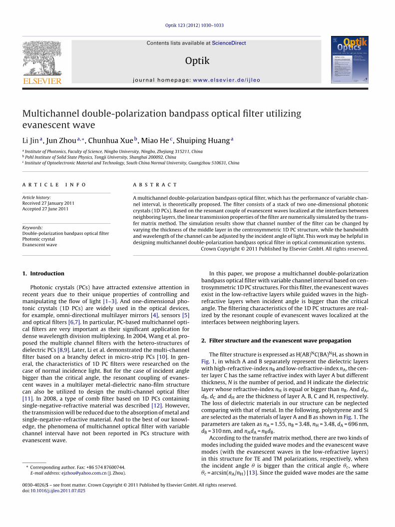
The filter structure is expressed as H(AB)NC(BA)NH, as shown inFig. 1, in which A and B separately represent the dielectric layerswith high-refractive-index nB and low-refractive-index nA, the cen-ter layer C has the same refractive index with layer A but differentthickness, N is the number of period, and H indicate the dielectriclayer whose refractive-index nH is equal or bigger than nB. And dA,dB, dC and dH are the thickness of layer A, B, C and H, respectively.The loss of dielectric materials in our structure can be neglectedcomparing with that of metal. In the following, polystyrene and Siare selected as the materials of layer A and B as shown in Fig. 1. Theparameters are taken as nA = 1.55, nB = 3.48, nH = 3.48, dA = 696 nm,dB = 310 nm, and nAdA = nBdB.
According to the transfer matrix method, there are two kinds ofmodes including the guided wave modes and the evanescent wave
modes (with the evanescent waves in the low-refractive layers)in this structure for TE and TM polarizations, respectively, whenthe incident angle � is bigger than the critical angle �c, where�c = arcsin(nA/nH) [13]. Since the guided wave modes are the samell rights reserved.
L. Jin et al. / Optik 123 (2012) 1030– 1033 1031
alettbotfifatm
3
fiTa1etatii
Fip(
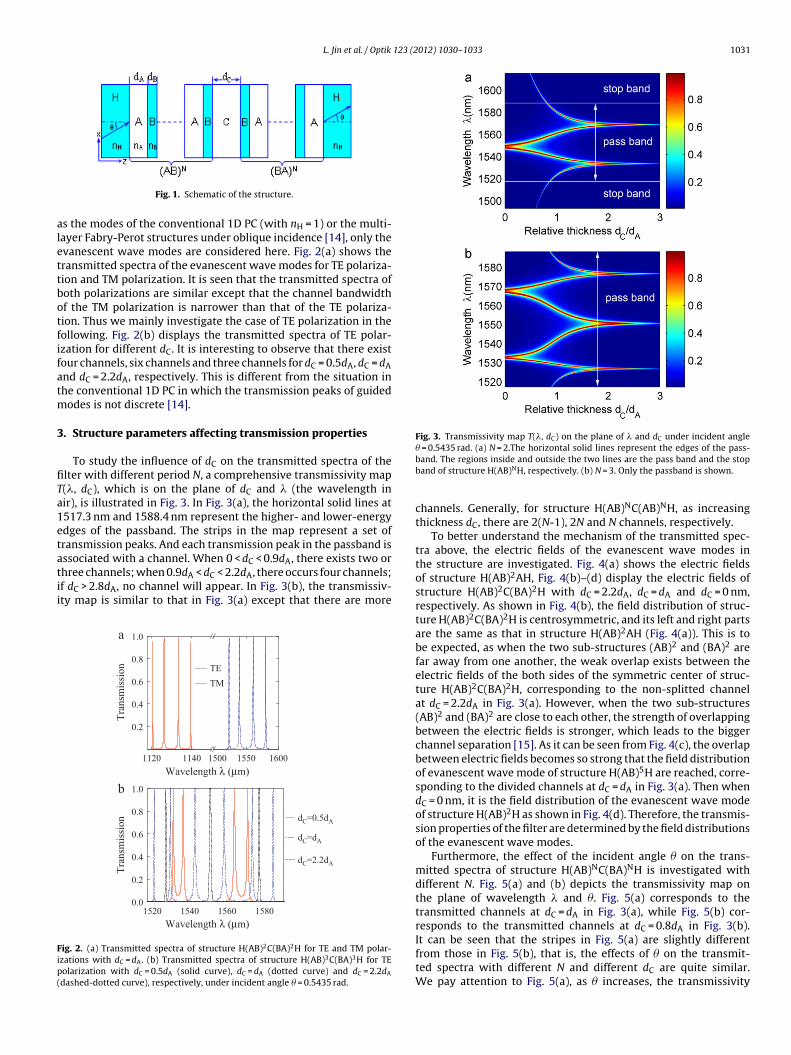
Fig. 3. Transmissivity map T(�, dC) on the plane of � and dC under incident angle� = 0.5435 rad. (a) N = 2.The horizontal solid lines represent the edges of the pass-
Fig. 1. Schematic of the structure.
s the modes of the conventional 1D PC (with nH = 1) or the multi-ayer Fabry-Perot structures under oblique incidence [14], only thevanescent wave modes are considered here. Fig. 2(a) shows theransmitted spectra of the evanescent wave modes for TE polariza-ion and TM polarization. It is seen that the transmitted spectra ofoth polarizations are similar except that the channel bandwidthf the TM polarization is narrower than that of the TE polariza-ion. Thus we mainly investigate the case of TE polarization in theollowing. Fig. 2(b) displays the transmitted spectra of TE polar-zation for different dC. It is interesting to observe that there existour channels, six channels and three channels for dC = 0.5dA, dC = dAnd dC = 2.2dA, respectively. This is different from the situation inhe conventional 1D PC in which the transmission peaks of guided
odes is not discrete [14].
. Structure parameters affecting transmission properties
To study the influence of dC on the transmitted spectra of thelter with different period N, a comprehensive transmissivity map(�, dC), which is on the plane of dC and � (the wavelength inir), is illustrated in Fig. 3. In Fig. 3(a), the horizontal solid lines at517.3 nm and 1588.4 nm represent the higher- and lower-energydges of the passband. The strips in the map represent a set ofransmission peaks. And each transmission peak in the passband is
ssociated with a channel. When 0 < dC < 0.9dA, there exists two orhree channels; when 0.9dA < dC < 2.2dA, there occurs four channels;f dC > 2.8dA, no channel will appear. In Fig. 3(b), the transmissiv-ty map is similar to that in Fig. 3(a) except that there are more160015501140 15001120
0.2
0.4
0.6
0.8
1.0a
Tran
smis
sion TE
TM
15801560154015200.0
0.2
0.4
0.6
0.8
1.0
Tran
smis
sion
Wavelength λ (μm)
Wavelength λ (μm)
dC=0.5dA
dC=d A
dC=2.2dA
b
ig. 2. (a) Transmitted spectra of structure H(AB)2C(BA)2H for TE and TM polar-zations with dC = dA. (b) Transmitted spectra of structure H(AB)3C(BA)3H for TEolarization with dC = 0.5dA (solid curve), dC = dA (dotted curve) and dC = 2.2dA
dashed-dotted curve), respectively, under incident angle � = 0.5435 rad.
band. The regions inside and outside the two lines are the pass band and the stopband of structure H(AB)NH, respectively. (b) N = 3. Only the passband is shown.
channels. Generally, for structure H(AB)NC(AB)NH, as increasingthickness dC, there are 2(N-1), 2N and N channels, respectively.
To better understand the mechanism of the transmitted spec-tra above, the electric fields of the evanescent wave modes inthe structure are investigated. Fig. 4(a) shows the electric fieldsof structure H(AB)2AH, Fig. 4(b)–(d) display the electric fields ofstructure H(AB)2C(BA)2H with dC = 2.2dA, dC = dA and dC = 0 nm,respectively. As shown in Fig. 4(b), the field distribution of struc-ture H(AB)2C(BA)2H is centrosymmetric, and its left and right partsare the same as that in structure H(AB)2AH (Fig. 4(a)). This is tobe expected, as when the two sub-structures (AB)2 and (BA)2 arefar away from one another, the weak overlap exists between theelectric fields of the both sides of the symmetric center of struc-ture H(AB)2C(BA)2H, corresponding to the non-splitted channelat dC = 2.2dA in Fig. 3(a). However, when the two sub-structures(AB)2 and (BA)2 are close to each other, the strength of overlappingbetween the electric fields is stronger, which leads to the biggerchannel separation [15]. As it can be seen from Fig. 4(c), the overlapbetween electric fields becomes so strong that the field distributionof evanescent wave mode of structure H(AB)5H are reached, corre-sponding to the divided channels at dC = dA in Fig. 3(a). Then whendC = 0 nm, it is the field distribution of the evanescent wave modeof structure H(AB)2H as shown in Fig. 4(d). Therefore, the transmis-sion properties of the filter are determined by the field distributionsof the evanescent wave modes.
Furthermore, the effect of the incident angle � on the trans-mitted spectra of structure H(AB)NC(BA)NH is investigated withdifferent N. Fig. 5(a) and (b) depicts the transmissivity map onthe plane of wavelength � and �. Fig. 5(a) corresponds to thetransmitted channels at dC = dA in Fig. 3(a), while Fig. 5(b) cor-responds to the transmitted channels at dC = 0.8dA in Fig. 3(b).
It can be seen that the stripes in Fig. 5(a) are slightly differentfrom those in Fig. 5(b), that is, the effects of � on the transmit-ted spectra with different N and different dC are quite similar.We pay attention to Fig. 5(a), as � increases, the transmissivity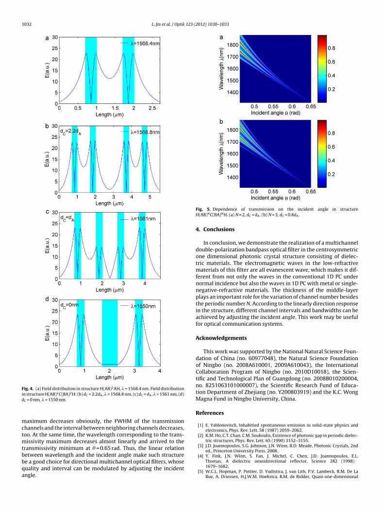
1032 L. Jin et al. / Optik 123 (2012) 1030– 1033
Fig. 4. (a) Field distribution in structure H(AB)2AH, � = 1568.4 nm. Field distributionid
mctmtbbqa
[4] Y. Fink, J.N. Winn, S. Fan, J. Michel, C. Chen, J.D. Joannopoulos, E.L.
n structure H(AB)2C(BA)2H: (b) dC = 2.2dA, � = 1568.8 nm, (c) dC = dA, � = 1561 nm, (d)C = 0 nm, � = 1550 nm.
aximum decreases obviously, the FWHM of the transmissionhannels and the interval between neighboring channels decreases,oo. At the same time, the wavelength corresponding to the trans-
issivity maximum decreases almost linearly and arrived to theransmissivity minimum at � = 0.65 rad. Thus, the linear relationetween wavelength and the incident angle make such structure
e a good choice for directional multichannel optical filters, whoseuality and interval can be modulated by adjusting the incidentngle.Fig. 5. Dependence of transmission on the incident angle in structureH(AB)NC(BA)NH. (a) N = 2, dC = dA, (b) N = 3, dC = 0.8dA.
4. Conclusions
In conclusion, we demonstrate the realization of a multichanneldouble-polarization bandpass optical filter in the centrosymmetricone dimensional photonic crystal structure consisting of dielec-tric materials. The electromagnetic waves in the low-refractivematerials of this filter are all evanescent wave, which makes it dif-ferent from not only the waves in the conventional 1D PC undernormal incidence but also the waves in 1D PC with metal or single-negative-refractive materials. The thickness of the middle-layerplays an important role for the variation of channel number besidesthe periodic number N. According to the linearly direction responsein the structure, different channel intervals and bandwidths can beachieved by adjusting the incident angle. This work may be usefulfor optical communication systems.
Acknowledgements
This work was supported by the National Natural Science Foun-dation of China (no. 60977048), the Natural Science Foundationof Ningbo (no. 2008A610001, 2009A610043), the InternationalCollaboration Program of Ningbo (no. 2010D10018), the Scien-tific and Technological Plan of Guangdong (no. 2008B010200004,no. 8251063101000007), the Scientific Research Fund of Educa-tion Department of Zhejiang (no. Y200803919) and the K.C. WongMagna Fund in Ningbo University, China.
References
[1] E. Yablonovitch, Inhabitied spontaneous emission in solid-state physics andelectronics, Phys. Rev. Lett. 58 (1987) 2059–2062.
[2] K.M. Ho, C.T. Chan, C.M. Soukoulis, Existence of photonic gap in periodic dielec-tric structures, Phys. Rev. Lett. 65 (1990) 3152–3155.
[3] J.D. Joannopoulos, S.G. Johnson, J.N. Winn, R.D. Meade, Photonic Crystals, 2nded., Princeton University Press, 2008.
Thomas, A dielectric omnidirectional reflector, Science 282 (1998)1679–1682.
[5] W.C.L. Hopman, P. Pottier, D. Yudistira, J. van Lith, P.V. Lambeck, R.M. De LaRue, A. Driessen, H.J.W.M. Hoekstra, R.M. de Ridder, Quasi-one-dimensional

123 (2
[
[
[
[
L. Jin et al. / Optik
photonic crystal as a compact building-block for refractometric optical sensors,IEEE J. Sel. Top. Quantum Electron. 11 (2005) 11–16.
[6] G.Q. Liang, P. Han, H.Z. Wang, Narrow frequency and sharp angular defect modein one-dimensional photonic crystals from a photonic heterostructure, Opt.Lett. 29 (2004) 192–194.
[7] X. Qin, P. Gu, B. Guo, Utilizing one-dimensional dual-periodical thin-film pho-tonic crystals to design the polarization band-pass filters, Proc. SPIE 5644 (2005)647.
[8] Z.S. Wang, L. Wang, Y.G. Wu, L.Y. Chen, X.S. Chen, W. Lu, Multiple channeledphenomena in heterostructures with defects mode, Appl. Phys. Lett. 84 (2004)
1629–1631.[9] Z. Wang, R.W. Peng, F. Qiu, X.Q. Huang, M.S. Wang, A. Hu, S.S. Jiang, D.Feng, Selectable-frequency and tunable-Q perfect transmissions of electromag-netic waves in dielectric heterostructures, Appl. Phys. Lett. 84 (2004) 3969–3971.
[[
012) 1030– 1033 1033
10] Y.H. Li, H.T. Jiang, L. He, H.Q. Li, Y.W. Zhang, H. Chen, Multichanneled filter basedon a branchy defect in microstrip photonic crystal, Appl. Phys. Lett. 88 (2006)081106, 3.
11] Simin Feng, J. Merle Elson, Pamela L. Overfelt, Optical properties of multilayermetal-dielectric nanofilms with all-evanescent modes, Opt. Exp. 13 (2005)4113–4124.
12] X.Y. Hu, Z. Liu, Q.H. Gong, Tunable multichannel filter in photonic crystalheterostructure containing permeability-negative materials, Phys. Lett. A 372(2008) 333–339.
13] Y.T. Fang, Z.C. Liang, Unusual transmission through usual one-dimensional pho-
tonic crystals in the presence of evanescent wave, Opt. Commun. 283 (2010)2102–2108.14] Pochi Yeh, Optical Waves in Layered Media, Wiley, 1988.15] J.D. Cox, M.R. Singh, Resonant tunneling in photonic double quantum well
heterostructures, Nanoscale Res. Lett. 5 (2010) 484–488.