Embed Size (px)
Citation preview
This is a preprint of the following article, which is available from http://mdolab.engin.umich.edu/content/multidisciplinary-design-optimization-offshore-wind-turbines-minimum-levelized-cost-energy. The publishedarticle may differ from this preprint.T. Ashuri, M.B. Zaaijer, J. R. R. A. Martins, G.J.W. van Bussel and G.A.M. van Kuik. Multidisciplinary DesignOptimization of Offshore Wind Turbines for Minimum Levelized Cost of Energy. Renewable Energy (In press), 2014
Multidisciplinary Design Optimization of Offshore WindTurbines for Minimum Levelized Cost of Energy
Turaj Ashuri1, Michiel B. Zaaijer2, Joaquim R.R.A Martins1, Gerard J.W. van Bussel2,and Gijs A.M. van Kuik2
1University of Michigan, Department of Aerospace Engineering, Ann Arbor, MI 48109, USA2Delft University of Technology, Department of Aerodynamics and Wind Energy,
Kluyverweg 1, 2629 HS, Delft, The Netherlands
Abstract This paper presents a method for multidisciplinary design optimization of offshore wind tur-bines at system level. The formulation and implementation that enable the integrated aerodynamic andstructural design of the rotor and tower simultaneously are detailed. The objective function to be minimizedis the levelized cost of energy. The model includes various design constraints: stresses, deflections, modalfrequencies and fatigue limits along different stations of the blade and tower. The rotor design variables are:chord and twist distribution, blade length, rated rotational speed and structural thicknesses along the span.The tower design variables are: tower thickness and diameter distribution, as well as the tower height. Forthe other wind turbine components, a representative mass model is used to include their dynamic interac-tions in the system. To calculate the system costs, representative cost models of a wind turbine locatedin an offshore wind farm are used. To show the potential of the method and to verify its usefulness, the5 MW NREL wind turbine is used as a case study. The result of the design optimization process shows2.3% decrease in the levelized cost of energy for a representative Dutch site, while satisfying all the designconstraints.
Contents1 Introduction . . . . . . . . . . . . . . . . . . . . . . . . . . . . . . . . . . . . . . . . . . . . . . . 2
1.1 Rotor design studies . . . . . . . . . . . . . . . . . . . . . . . . . . . . . . . . . . . . . . . . . 21.2 Tower design studies . . . . . . . . . . . . . . . . . . . . . . . . . . . . . . . . . . . . . . . . . 3
2 Methodology . . . . . . . . . . . . . . . . . . . . . . . . . . . . . . . . . . . . . . . . . . . . . . 42.1 MDO Architecture . . . . . . . . . . . . . . . . . . . . . . . . . . . . . . . . . . . . . . . . . . 42.2 Optimization problem formulation . . . . . . . . . . . . . . . . . . . . . . . . . . . . . . . . . 52.3 Practical considerations . . . . . . . . . . . . . . . . . . . . . . . . . . . . . . . . . . . . . . . 11
3 Results . . . . . . . . . . . . . . . . . . . . . . . . . . . . . . . . . . . . . . . . . . . . . . . . . . 133.1 Optimized gross properties . . . . . . . . . . . . . . . . . . . . . . . . . . . . . . . . . . . . . 133.2 Design drivers . . . . . . . . . . . . . . . . . . . . . . . . . . . . . . . . . . . . . . . . . . . . . 163.3 Objective function . . . . . . . . . . . . . . . . . . . . . . . . . . . . . . . . . . . . . . . . . . 18
4 Discussion and conclusions . . . . . . . . . . . . . . . . . . . . . . . . . . . . . . . . . . . . . . 195 Future work . . . . . . . . . . . . . . . . . . . . . . . . . . . . . . . . . . . . . . . . . . . . . . . 206 Acknowledgments . . . . . . . . . . . . . . . . . . . . . . . . . . . . . . . . . . . . . . . . . . . 207 References . . . . . . . . . . . . . . . . . . . . . . . . . . . . . . . . . . . . . . . . . . . . . . . . 20
1

1 IntroductionDue to concerns over the environmental impact of fossil fuel emissions and fossil fuel exhaustion, the amountof wind energy generated has been increasing at a faster pace in the last few years . Although wind energyhas evolved considerably during the last decades, there are many advances required to design economic andreliable wind turbines.
One of the promising concepts that can contribute to these goals is the use of multidisciplinary designoptimization (MDO). MDO uses numerical optimization techniques to design engineering systems involvingmultiple disciplines or components Martins and Lambe [2013].
In the context of wind power design optimization two subjects are of interest: the design optimizationof wind turbines and wind farm layout optimization1. The scope of this paper is wind turbine designoptimization considering aerodynamics and structure as the two main disciplines, with the simultaneousdesign of the rotor and tower as the two main components.
Over the past decade, several authors have developed techniques for optimizing either the rotor or tower,with most of the studies being focused on rotor optimization. A brief overview of these studies is presentedbelow.
1.1 Rotor design studiesA method for optimizing wind turbine gross parameters, such as rotor diameter and hub height for a specificsite was presented by Diveux et al. [2001]. Similarly, Fuglsang and Thomsen [2001] conducted rotor designoptimization with several site-specific environmental inputs to minimize the cost of energy (COE). Beniniand Toffolo [2002] used a multi-objective evolutionary algorithm to optimize the aerodynamic shape of astall-regulated wind turbine blade.
Maalawi and Negm [2002] presented an optimization study to make an exact placement of natural fre-quencies of the blade to avoid resonance. Maalawi and Badr [2003] optimized the rotor chord and twistto produce the largest possible power output. Jureczko et al. [2005] studied the blade structural lay-upoptimization to minimize its mass.
The blade structural optimization of laminated composite shells was studied by Lund and Stegmann[2005]. The shape and thickness of the structure were fixed and the problem dealt entirely with the design ofthe lay-up of the composite laminate. Méndez and Greiner [2006] used a genetic algorithm to obtain optimalchord and twist distributions in wind turbine blades to maximize the mean expected power depending onthe Weibull wind distribution at a specific site. Lee et al. [2007] studied blade shape optimization to obtainthe maximum average annual power for a given offshore wind farm. A two-step optimization procedure wasestablished: the operating condition optimization as step one, and the geometric blade shape design andblade performance analysis optimization as step two.
Kenway and Martins [2008] studied the blade aerostructural design optimization to maximize the energyoutput while considering site-specific winds. Xudong et al. [2009] used an aeroelastic model of the rotor todo aerodynamic and structural design with the rotor torque and thrust as the design constraints.
Blade aerodynamic shape optimization using different tip-loss corrections in blade element momentum(BEM) theory was studied by Clifton-Smith [2009]. The blade aerodynamic shape optimization with aprobabilistic approach was studied by Lee et al. [2010].
To enhance the aerodynamic performance of blades, the sectional aerodynamic design optimization wasstudied by Kwon et al. [2012]. Design optimization of a wind turbine blade was presented by Jeong et al.[2012] to minimize the fluctuation of the bending moment of the blade in turbulent wind.
Blade structural and aerodynamic optimization was presented by Bottasso et al. [2012]. Design optimiza-tion is performed by a two-stage process. First, an aerodynamic shape optimization step is performed tomaximize annual energy production (AEP), followed by a structural blade optimization to minimize weight.Second, both designs are combined to yield the final optimum solution.
The system-level design of a wind turbine blade using a multi-level optimization approach was studiedby Maki et al. [2012]. The shape optimization of the blade to maximize AEP, and the structural design of theblade to minimize the bending moment at the root were considered as single-disciplinary optimization strat-
1For wind farm layout optimization the interested reader can consult various references Beyer et al. [1996], Castro Mora et al.[2007], Emami and Noghreh [2010], Grady et al. [2005], Kusiak and Song [2010], Marmidis et al. [2008], Meyers and Meneveau[2012].
2

egy. Cost of energy was considered as the overall system-level objective, while performance improvementsat the two single-disciplines were pursued at the same time.
1.2 Tower design studiesNegm and Maalawi [2000] examined several optimization models such as mass reduction, stiffness maximiza-tion and vibration minimization for the design of a tubular wind turbine tower structures. Wind turbinetower optimization was studied by Yoshida [2006] using a genetic algorithm to minimize the mass of thetower. Uys et al. [2007] developed a procedure to minimize the cost of a mildly conical steel wind turbinetower to meet the structural requirements of slender structures.
A formulation for the optimal design of reinforced concrete towers was presented by Silva et al. [2008]. Dif-ferent tower heights were analyzed to obtain the best formulation in terms of cost. An integrated reliability-based design optimization of offshore towers was presented by Karadeniz et al. [2009]. As a demonstration,they optimized a tripod tower subject to reliability constraints based on limit states of the critical stress,buckling and the natural frequency.
Similarly, Petrini et al. [2010] proposed a system approach as a conceptual method for the design ofoffshore wind turbine structures. Numerical analysis has been performed to compare the design of threedifferent support structure types (monopile, tripod and jacket) with respect to extreme loads, buckling,natural frequencies and life-time loads.
Torcinaro et al. [2010] considered the optimization process of an offshore support structure intendedfor a 5 to 6 MW turbine. Support structure geometry and thickness were the design variables subjectedto constraints on stresses, buckling and deformation. Mass is optimized using gradient based optimizationalgorithm.
Thiry et al. [2011] used a genetic algorithm to minimize the structural weight of a wind turbine supportstructure for an offshore application. Haghi et al. [2012] used a similar approach, but instead of using agenetic algorithm he used gradient-based optimization. Zwick et al. [2012] presented an iterative optimizationapproach for a first stage of a complete analysis of a full-height lattice tower concept. The aim was to finda light-weight design to fulfill the ultimate and fatigue limit states of the members.
Molde [2012] used Spall’s simultaneous perturbation stochastic approximation method Spall [1998] toautomatically optimize thickness and diameter of the members in offshore lattice tower support structures.The objective was to minimize tower weight. Karpat [2013] minimized the cost of wind turbine steel towerswith ring stiffeners using a particle swarm optimization algorithm. The height and thickness of a flat ringstiffener, and the wall thickness and the diameter at some stations along the tower were selected as thedesign variables, subject to buckling and frequency constraints.
The work presented herein addresses some of the shortcomings of the previous work mentioned above bydeveloping an integrated MDO method to simultaneously design the rotor and the tower of a wind turbine atthe system level. The design found in this way is superior to the design found by optimizing each disciplineor component separately, since MDO of the rotor and tower incorporates the dynamic interaction betweenthe disciplines and components. This interaction is particularly important, due to the following factors:
Structural flexibility: Rotor and tower are the most flexible components of a wind turbine, and togetherthey dominate the global dynamics of the system.
Energy yield: Rotor and tower (also the controller) have the highest impact on the annual energy yield ofthe wind turbine, therefore important to optimize simultaneously.
Cost: Rotor and tower (also the gearbox) have the highest cost share of a wind turbine. Typically, rotorand tower make up to 30% of the capital cost of a wind turbine Tegen et al. [2013].
The remainder of the paper is structured as follows. First, the integrated architecture used to modelthe multidisciplinary aspects of the wind turbine is presented. This is an important aspect, since existingcomputational tools are not well suited to be used with numerical optimization that is fully automated2.
We then describe how this integrated multidisciplinary model is linked to the optimization algorithm.This enables running the design optimization process for as many iterations as the optimizer needs to findthe optimum. Then, to verify the capability and effectiveness of the method, the 5MW NREL research wind
2See Ashuri and Zaaijer [2007] for a list of the main computational tools currently used for wind turbine design.
3

turbine Jonkman et al. [2009] is used as a baseline design to optimize. Both the rotor and tower are designedsimultaneously with all their relevant design constraints present. Finally, the results of the optimized 5MWturbine are compared with the 5MW NREL wind turbine, followed by a discussion and conclusions.
2 MethodologyAmong the several MDO architectures described in the literature, this study implements the multidisciplinaryfeasible (MDF) architecture explained by Martins and Lambe [2013]. In the next subsection we describehow MDF is implemented, including the details of how the various models are coupled and how the overalloptimization process is sequenced.
2.1 MDO ArchitectureWith the MDF architecture, the idea is to directly couple an optimizer to a multidisciplinary analysis model,as shown in Figure 1. We use the extended design structure matrix (XDSM) standard developed by Lambeand Martins [2012] for the diagram. The aerodynamic and structural design variables are passed to themultidisciplinary analysis, which computes the objective function and constraints for the coupled system.Then, the objective and constraints are passed back to be assessed by the optimizer. This iterative approachcontinues until the convergence is achieved.
Optimizer Aerodynamic DV Structural DV Structural DVAerodynamic &structural DV
AEP Aerodynamics Loads Loads
Mass models Mass Mass
Constraints Structure Loads
System cost Cost models
Figure 1: Multidisciplinary feasible architecture to couple the optimizer to the multidisciplinary analysismodel. Green box is the optimizer, rounded blue boxes are the analysis models, gray parallelograms are data(design variables (DV), loads, mass, costs, annual energy production (AEP) and constraints) and gray linesshow the data flow that is from top to bottom and left to right on the upper triangular part, and bottomto top and right to left on the lower triangular part. Table 2 lists the aerodynamic and structural designvariables shown in this figure.
To compute the objective function and design constraints, a multidisciplinary analysis is required thatcouples the computational tools representing the various disciplines involved. Among the many computa-tional tools that have been developed for the wind energy community, a number of NREL tools are used,and they are listed in Table 1. These tools are all open source, which makes them particularly well suitedfor research purposes.
The computational tools listed in Table 1 are in principle independent and not designed with couplingin mind. Thus, the data transfer between these codes has to be done manually by the designer. To make anintegrated and automated design process, we coupled these computational tools such that the final productcould be easily linked with optimization software using the MDF architecture.
Figure 2 shows how the tools are coupled in a framework that captures the static and dynamic behavior ofthe wind turbine, and evaluates the design constraints and objective function. This integration is achieved
4

Table 1: Selection of the computational toolsTool Usage Reference
TurbSim Simulates the 3D turbulent wind flow Jonkman andBuhl [2007]
AeroDyn Models the steady and unsteady aerodynamic loads Laino andHansen [2002]
AirfoilPrep Corrects 2D airfoil data for 3D effects Viterna andJanetzke [1982]
FAST Models the aeroelastic behavior of the wind turbine Jonkman andBuhl [2004]
BModes Computes mode shapes and frequencies Bir [2007]Crunch Postprocesses the FAST output data Buhl [2003]Cost-mass mod-els
Computes mass and cost of components Fingersh et al.[2006]
Fatigue Computes rain-flow cycle counted time series Frendahl andRychlik [1993]
by a script that manages the data flow between all the codes. The script is used to manage the designoptimization process such that:
1. The coupling of different tools is effective and yields the correct result.
2. All data exchanges are automatic.
3. All design changes are reflected in the relevant locations in the framework.
2.2 Optimization problem formulationIn order to solve the correct design problem, we must define the optimization problem with the appropriateobjective, design variable and design constraints. The general nonlinear optimization problem is:
Find x = {x1, . . . , xn} that minimizes f(x) (1)
where f is the objective function, and x is an n-dimensional vector of design variables to be found, withlower and upper bounds:
xlower ≤ x ≤ xupper (2)
The problem is subject to inequality and equality constraints:
gj {x} ≥ 0 (3)
hk(x) = 0 (4)
We now describe what these general terms are in the specific case of the wind turbine problem that wesolve.
2.2.1 Design variablesA design variable is a parameter that the optimizer controls, whose influence on the constraints and objectivefunction is evaluated in the analysis phase. In this paper, the rotor optimization controls 18 design variablesthat consist of blade external geometry variables, blade structural thickness variables and rotor rotationalspeed. The blade geometry variables are 4 chord lengths, 2 twists along the span and blade length. Thestructural thicknesses of the composite lay-ups are spar thicknesses at 3 stations, shell thicknesses at 4stations, and web thicknesses at 3 stations along the blade. The rotational speed of the rotor together withthe blade length control the tip-speed of the blade, which is a crucial design constraint.
5

Op
tim
izer
Bla
de
len
gth
&hu
bh
eigh
tA
erod
yn
amic
DV
Aer
dyn
amic
DV
Str
uct
ura
lD
VS
tru
tura
lD
VS
tru
ctu
ral
DV
Aer
od
yn
amic
&st
ruct
ura
lD
VS
tru
ctu
ral
DV
Tu
rbSim
3Dw
ind
Air
filP
rep
3Dco
rrec
tion
AE
PA
eroD
yn
Aer
od
yn
amic
load
sA
erod
yn
am
iclo
ads
Mas
sm
od
els
Mas
sM
ass
Mas
s
Mod
alfr
equ
ency
BM
od
esM
od
al
shap
e&
freq
uen
cy
Tip
-sp
eed
&d
efor
mat
ion
sFA
ST
Str
uct
ura
llo
ad
sS
tru
ctu
ral
load
s
Syst
emco
stC
ost
mod
els
Max
stre
ssC
run
chS
tres
ssi
gnal
s
Fat
igu
ed
amag
eF
ati
gue
Figure 2: Block diagram of the MDO framework to show the data and process flow of different computationalcodes. Table 2 lists the aerodynamic and structural design variables shown in this figure. Green box is theoptimizer, rounded blue boxes are the analysis models, gray parallelograms are data, and gray lines showthe data flow that is from top to bottom and left to right on the upper triangular part, and bottom to topand right to left on the lower triangular part.
6
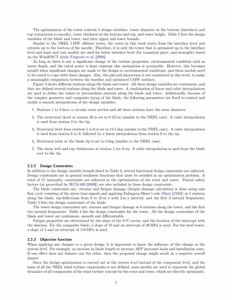
The optimization of the tower controls 5 design variables: tower diameter at the bottom (interface) andtop (connection to nacelle), tower thickness at the bottom and top, and tower height. Table 2 lists the designvariables of the blade and tower, and their upper and lower bounds.
Similar to the NREL 5MW offshore tower, the tower in this work starts from the interface level andextends up to the bottom of the nacelle. Therefore, it is only the tower that is optimized up to the interfacelevel and mass and cost models are used for below interface level (for transition piece, and monopile) basedon the WindPACT study Fingersh et al. [2006].
As long as there is not a significant change of the turbine properties, environmental condition such aswater depth, and the rated power is kept constant this assumption is acceptable. However, this becomesinvalid when significant changes are made to the design or environmental conditions, and these models needto be tuned to cope with these changes. Also, the pile-soil interaction is not considered in this work, to makea meaningful comparison between the baseline and optimized 5MW turbines.
Figure 3 shows different stations along the blade and tower. All these design variables are continuous, andthey are defined several stations along the blade and tower. A combination of linear and cubic interpolationsare used to define the values at intermediate stations along the blade and tower. Additionally, because ofthe complex geometry and composite layup of the blade, the following parameters are fixed to control andenable a smooth interpolation of the design variables:
1. Stations 1 to 3 have a circular cross section and all three stations have the same diameter.
2. The structural chord at station 20 is set to 0.12 cm (similar to the NREL case). A cubic interpolationis used from station 3 to the tip.
3. Structural twist from stations 1 to 6 is set to 13.1 deg (similar to the NREL case). A cubic interpolationis used from station 6 to 9, followed by a linear interpolation from station 9 to the tip.
4. Structural twist at the blade tip is set to 0 deg (similar to the NREL case).
5. The shear web and cap thicknesses at station 1 are 0 cm. A cubic interpolation is used from the bladeroot to the tip.
2.2.2 Design ConstraintsIn addition to the design variable bounds listed in Table 2, several functional design constraints are enforced.Design constraints are in general nonlinear functions that must be satisfied in an optimization problem. Atotal of 51 inequality constraints are enforced in the optimization of the rotor and tower. Partial safetyfactors (as prescribed by IEC61400 [2009]) are also included in these design constraints.
The blade constraints are: stresses and fatigue damage (fatigue damage calculation is done using rainflow cycle counting of the stress time-signals and applying Palmgren-Miner’s rule Miner [1945]) at 5 stationsalong the blade, tip-deflections from 9 to 25m/s with 2m/s interval, and the first 3 natural frequencies.Table 3 lists the design constraints of the blade.
The tower design constraints are: stresses and fatigue damage at 6 stations along the tower, and the firsttwo natural frequencies. Table 4 list the design constraints for the tower. All the design constraints of theblade and tower are continuous, smooth and differentiable.
Fatigue properties are determined by the slope of the S-N curves, and the location of the intercept withthe abscissa. For the composite blade, a slope of 10 and an intercept of 40MPa is used. For the steel tower,a slope of 4 and an intercept of 110MPa is used.
2.2.3 Objective functionWhen applying any changes to a given design, it is important to know the influence of this change at thesystem level. For example, an increase in blade length to increase AEP increases loads and installation costs.If one effect does not balance out the other, then the proposed change might result in a negative overallimpact.
Since the design optimization is carried out at the system level instead of the component level, and themass of all the NREL wind turbine components is not defined, mass models are used to represent the globaldynamics of all components of the wind turbine (except for the rotor and tower, which are directly optimized).
7

Figure 3: Different stations along the blade and tower to show the geometry and the approximate locationof each station. Station 1 of the blade defines the root and station 20 the tip. Station 1 of the tower definesthe interface level and station 22 the tower top.
8
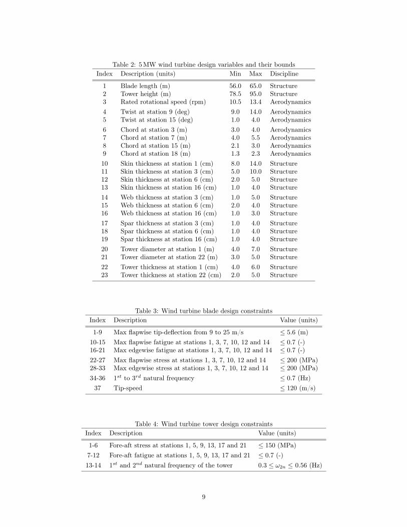
Table 2: 5MW wind turbine design variables and their boundsIndex Description (units) Min Max Discipline
1 Blade length (m) 56.0 65.0 Structure2 Tower height (m) 78.5 95.0 Structure3 Rated rotational speed (rpm) 10.5 13.4 Aerodynamics4 Twist at station 9 (deg) 9.0 14.0 Aerodynamics5 Twist at station 15 (deg) 1.0 4.0 Aerodynamics6 Chord at station 3 (m) 3.0 4.0 Aerodynamics7 Chord at station 7 (m) 4.0 5.5 Aerodynamics8 Chord at station 15 (m) 2.1 3.0 Aerodynamics9 Chord at station 18 (m) 1.3 2.3 Aerodynamics10 Skin thickness at station 1 (cm) 8.0 14.0 Structure11 Skin thickness at station 3 (cm) 5.0 10.0 Structure12 Skin thickness at station 6 (cm) 2.0 5.0 Structure13 Skin thickness at station 16 (cm) 1.0 4.0 Structure14 Web thickness at station 3 (cm) 1.0 5.0 Structure15 Web thickness at station 6 (cm) 2.0 4.0 Structure16 Web thickness at station 16 (cm) 1.0 3.0 Structure17 Spar thickness at station 3 (cm) 1.0 4.0 Structure18 Spar thickness at station 6 (cm) 1.0 4.0 Structure19 Spar thickness at station 16 (cm) 1.0 4.0 Structure20 Tower diameter at station 1 (m) 4.0 7.0 Structure21 Tower diameter at station 22 (m) 3.0 5.0 Structure22 Tower thickness at station 1 (cm) 4.0 6.0 Structure23 Tower thickness at station 22 (cm) 2.0 5.0 Structure
Table 3: Wind turbine blade design constraintsIndex Description Value (units)
1-9 Max flapwise tip-deflection from 9 to 25 m/s ≤ 5.6 (m)10-15 Max flapwise fatigue at stations 1, 3, 7, 10, 12 and 14 ≤ 0.7 (-)16-21 Max edgewise fatigue at stations 1, 3, 7, 10, 12 and 14 ≤ 0.7 (-)22-27 Max flapwise stress at stations 1, 3, 7, 10, 12 and 14 ≤ 200 (MPa)28-33 Max edgewise stress at stations 1, 3, 7, 10, 12 and 14 ≤ 200 (MPa)34-36 1st to 3rd natural frequency ≤ 0.7 (Hz)37 Tip-speed ≤ 120 (m/s)
Table 4: Wind turbine tower design constraintsIndex Description Value (units)
1-6 Fore-aft stress at stations 1, 5, 9, 13, 17 and 21 ≤ 150 (MPa)7-12 Fore-aft fatigue at stations 1, 5, 9, 13, 17 and 21 ≤ 0.7 (-)13-14 1st and 2nd natural frequency of the tower 0.3 ≤ ω2n ≤ 0.56 (Hz)
9

In addition, instead of using a single-disciplinary objective function such as AEP (aerodynamics) or load-mass(structures), the levelized cost of energy (LCOE) is used as a multidisciplinary objective function.
The LCOE is a good objective function because it reflects the overall goal of wind energy production,and it also accounts for all the multidisciplinary trade-offs when a coupled analysis is performed at thesystem-level Ashuri [2012].
LCOE is a continuous, smooth and differentiable function, which enables the use of gradient-basedoptimization algorithms. To make a realistic estimation of the LCOE, it is assumed that all the costelements correspond to a wind turbine that operates in an offshore farm. These cost elements are explainedby Fingersh et al. [2006], and the details are not repeated here. The LCOE covers the following items:
Turbine Capital Cost (TCC): This is the cost of all the components of a wind turbine. These are:blades, hub, pitch mechanism and bearings, nose cone, low speed shaft and bearings, gearbox, mechan-ical brake, high speed shaft and coupling, generator, power electronics, yaw drive and bearing, mainframe, electrical connections, hydraulic system, cooling system, nacelle cover, control equipment, safetysystem, condition monitoring, tower, marinization (extra cost to protect against marine environmentlike salty water).
Balance of Station (BOS): This is the cost of following items: monopile, port and staging equipment, tur-bine installation, electrical interface and connections, permits, engineering, site assessment, personnelaccess equipment, scour protection, transportation, offshore warranty premium and decommissioning.
Initial Capital Cost (ICC): Summation of the TCC and BOS costs.
Levelized Replacement Cost (LRC): This is the cost of major replacements and overhauls, distributedover the life time of the wind turbine.
Operations and Maintenance (O&M): Cost associated to fix failures of mechanical or electrical com-ponents and all the regular and irregular inspection of the wind turbine.
LCOE is calculated using the following equation:
LCOE =
((ICC× FCR) + LRC+O&M
AEP
)(5)
Here, FCR is the Fixed Charge Rate, which includes construction financing, financing fees, return on debtand equity, depreciation, income tax, and property tax and insurance. AEP is the amount of generatedelectricity in a year for a given wind speed distribution, f(V ). It also includes the mechanical and electricalconversion losses, and machine availability. The wind speed distribution is given by the Weibull distribution:
f(V ) =
(k
c
)(V
c
)k−1
exp
[−(V
c
)k]
(6)
where V is the wind velocity, k is the shape factor, and c the scale factor. In this paper, k is 2, and c is 9.47.These values typically represent the condition of the Dutch part of the North Sea Brand [2008]. Then, theAEP production can be expressed as:
AEP ≈ 8760×cut−out∑i=cut−in
P (Vi) · f(Vi) (7)
in which 8760 is the number of hours per year, P (V ) is the power curve of the wind turbine, and the indexi represents the discretized wind speed with a bin interval of 2, i.e. 5, 7, . . . , 25.
However, these cost models were calibrated based on 2002 costs and should be updated based on thecost of materials and products in the present time to account for the inflation of materials, products andlabor. To compensate for this difference, a component cost escalation model based on the Producer PriceIndex (PPI) is used, as recommended by the WindPACT study. The PPI is an index that is updated on amonthly basis by the US Department of Labor, Bureau of Labor Statistics, to track the changes of costs ofproducts and materials over a wide range of industries and industrial products. The PPI related formulas
10

are sorted by North American Industry Classification System (NAICS) codes that provide a grouping systemof products 3.
2.2.4 External condition and design load case (DLC)An estimate of the loading conditions that a wind turbine experiences in its lifetime must be analyzed. Forthis estimate the IEC61400-3 standard is used, where the external conditions are site dependent and windturbine classes are defined in terms of wind speed and turbulence parameters at hub-height with a referenceperiod of 630 second (the first 30 second is ignored to avoid strange transient behavior) for each random seed.This paper uses the 2009 edition of IEC 61400-3 standard for defining the design load cases, and based onSection 7.4 of this standard, the design load cases used for simulations are defined in Table 5. The IEC-1Bclass is used for these load cases.
Table 5: Definition of DLCs based on IEC standardDesign Design Simulated Wind-wave Analysissituation load case wind (m/s) misalignment type
Power production 1.2 4 to 25 Aligned FatigueParked 6.1 50 Aligned Ultimate
For the fatigue limit state, a Normal Turbulence Model (NTM) during the power production mode isused. This model is applied from the cut-in to cut-out wind speed with 0 degree wind-wave misalignment.The fatigue damage obtained using this method is an overestimate, which yields a conservative design (sincethe damage from all different directions are accumulated in one direction). For the extreme limit state, anExtreme Wind Model (EWM) with a 50-year recurrence period is used. Again, no wind-wave misalignmentis considered in this case.
This setup results in 72 simulation scenarios (11 load cases for NTM with 6 random seeds and windspeed bin size of 2, and 1 load case for EMW-50 year with 6 random seeds and wind speed of 50m/s). Inthe authors’ experience, this is the minimum number of load cases that should be considered to obtain apractical design, as they are the design drivers in most cases. Considering more design load cases using thismethod is technically possible, but it requires more computational time.
2.3 Practical considerationsThere are some issues related to the MDO approach in this research that are unique, and therefore requirefurther explanation.
2.3.1 Multilevel optimization approachSince this research deals with the simultaneous design optimization of blade and tower, the number of designvariables is large. To overcome this problem, a size reduction technique should be employed to enable somecomputational time savings. An approach where the aerodynamic optimization is performed in sequence witha structural optimization is possible, but this would result in a suboptimal solution Chittick and Martins[2009]. Instead, the design variables are decomposed here that results in a bi-level optimization approach asshown in Figure 4.
In the first level, the blade length, tower height and rated rotational speed are optimized, while all otherdesign variables are fixed. The blade-tip-speed constraint is the only constraint involved here. This setupresults in an optimization problem that minimizes LCOE with respect to three design variables subject toone constraint.
After finding the optimum values of the blade length, tower height and rated rotational speed, the secondlevel optimization takes place. In the second level, blade length, tower height and rated rotational speed arefixed and all other design variables are varying. Here, all constraints except the blade-tip-speed constraintare enforced. The objective is to minimize LCOE with respect to 20 design variables subject to 50 designconstraints.
3United States Department of Labor, Producer Price Indexes, http://www.bls.gov/ppi/, retrieved on 01 November 2013
11

Level 1(CONLIN)
Level 2(LM)
Objective function: LCOE
Design variables: Blade length, tower height and rated rotational speed
Design constraints: • Functional: Blade tip-speed• Side: Blade length, tower height and rated rotational speed
Algorithm type: First order
Wind file generation:Every iteration
Objective function: LCOE
Design variables: All except blade length, tower height and rated rotational speed
Design constraints: • Functional: All except blade tip-speed• Side: All except blade length, tower height and rated rotational speed
Algorithm type: Second order
Wind file generation:Once
Converged?
(LCOEi+1 – LCOEi ≤ ξ)
No
Yes
Optimaldesign
Figure 4: Multilevel optimization approach of the wind turbine to decompose the design space and speed upthe optimization process
12

The evaluation of the objective function and design constraints takes on average 45 minutes of wall timefor level one, and 30 minutes for level two. These two levels take place at each global iteration of theoptimization process. Parallel computing is used to speed up the optimization process. The evaluation ofthe objective function and the design constraints requires computations at different wind speeds. In thiswork each wind speed was run on a separate CPU to enable a faster optimization iteration, and in total 14parallel computational nodes were used to optimize the design.
2.3.2 Optimization algorithmDue to the computational expense in computing the objective function and design constraints, a gradient-based algorithm is the best option in this case. For the first level, Convex linearization (CONLIN) is used,which is a first order algorithm Fleury [1989]. For the second level of the optimization process, a second orderalgorithm—the Lagrange Multiplier (LM) method—is used Birgin and Martinez [2008]. For both algorithms,the gradients are calculated using the finite-difference method.
The optimization process runs until an acceptable convergence on the objective function with a toleranceof 0.001 is obtained. This tolerance is achieved after 4 iterations of a multilevel optimization, and thereforeno further optimization is needed afterward.
It also should be noted that gradient-based optimization has the well-known problem of getting stuck inlocal minima. Starting the optimization from different point on the design space is an option, but this isnot considered in this research, since the aim of this paper is to use this framework and apply that on anexisting design and see how it works in practice rather than finding the global minimum.
2.3.3 Wind turbine control strategySimilar to the 5MW NREL wind turbine, a VS (Variable-speed) pitch-regulated control concept is used herewith the same DLL (Dynamic Link Library) file and parameters. For the below-rated region, a variable-speed strategy is used, where the generator torque controller maximizes the energy output by adjustingthe rotational speed. For the above-rated region, active pitch controller strategy is used where the PI(Proportional-integral) controller maintains the power output at 5MW by pitching the blade into or out ofthe wind Bianchi et al. [2006].
2.3.4 Evaluation of the design constraintsThe structural stresses are obtained by converting the load time series from the aeroelastic solver FAST to astress time series for every wind speed bin from cut-in to cut-out using Crunch. A peak-finding algorithm isused to find the maximum stress that appears as the design constraint. For doing life time fatigue calculation,rain flow cycle counting is applied on the FAST stress time series for every wind speed bin from cut-in tocut-out. Palmgren-Miner’s ruler is used to obtain the partial fatigue damage resulting from every wind speedbin, and each partial damage is added to obtain the cumulative fatigue damage.
The natural frequencies are based on the blade and tower mass and stiffness distribution, and are com-puted using BModes, which is a modal analysis code Bir [2007]. The blade-tower clearance is a direct outputof FAST. Tip-speed is obtained by multiplying the blade length to the rotor rotational speed for every windspeed from cut-in to cut-out.
3 ResultsThis section presents the results of the optimized 5MW NREL wind turbine. The goal of optimizing theNREL wind turbine is to show the potential of the optimization method and understand the design driversand trends for this type of turbine.
The results are categorized in three parts. First, the optimized gross properties of rotor and tower arepresented and compared with the original 5MW NREL design. Second, the design constraints of the systemare presented, with an emphasis on showing the design drivers of the 5MW optimized turbine. Third, theLCOE contributions from all the elements of the system are analyzed.
3.1 Optimized gross propertiesFigure 5 shows the chord distribution along the NREL and optimized blades. Note that the optimized bladeis 3.6% longer than the NREL blade (63.7m vs. 61.5m). As the figure shows, in the circular region (station
13

1 to 3 at the blade root), the optimized blade has slightly smaller diameter than the NREL blade. From theaerodynamic point of view this region does not contribute to power production and the slight decrease canbest be explained from structural point of view.
The reason for this reduction is mainly a better distribution of the mass and stiffness along the blade.Although it could be argued that the optimized blade is larger and experiences higher loads, and thereforea larger root diameter is required, it has a lower rated wind speed (because of larger rotor diameter), andthat balances out this effect.
The chord of the optimized blade shows an increase after the circular region when compared to the NRELblade, but the difference remains almost constant up to the vicinity of the blade tip.
0
0.5
1
1.5
2
2.5
3
3.5
4
4.5
5
0 0.1 0.2 0.3 0.4 0.5 0.6 0.7 0.8 0.9 1
Ch
ord
(m
)
Normalized blade length (-)
NREL Optimized
Figure 5: Chord distribution of the NREL and optimized blades
Figure 6 shows the twist distributions for the NREL and optimized blades. The twist angle is reducedfor the optimized blade outboard of the circular section, but then it matches the NREL blade twist at thetip. This is because of introducing a twist angle of zero at the tip as a hard constraint to be met by theoptimizer while interpolating the twist distribution. Therefore, by definition, both the optimized and theNREL blade twist distribution is zero at the tip that is mainly to minimize losses and noise.
Considering the fact that both rotors have a different chord, twist angle, blade length, and rated rotationalspeed, a one to one comparison is difficult to make. It is the combination of these properties that makes onedesign better over the other with respect to the objective function.
The blade thickness distribution is used to extract the flapwise and edgewise stiffnesses, and mass perunit length of the blade. The computation of the stiffness and other useful structural properties is basedon an analytical model of the blade, using the real geometry and the weight averaging method describedby Ashuri et al. [2010a]. Figure 7 shows the stiffness distribution along the blade of both designs. Theoptimized flapwise stiffness is lower near the root, but it increases toward the tip. In the edgewise direction,the optimized blade is generally more flexible than the NREL blade.
The mass per unit length for both the NREL and optimized blades is shown in Figure 8. The blade massof the 5MW NREL wind turbine is 17740 kg, while the optimized blade has a mass of 18490 kg, which is4.2% heavier. This additional mass is partly because the optimized blade is longer. Additionally, the massdistribution of the optimized blade is in general higher than the NREL blade.
Figure 9 shows the design variables of the optimized tower compared to the NREL tower. The mass and
14

0
1.4
2.8
4.2
5.6
7
8.4
9.8
11.2
12.6
14
0 0.1 0.2 0.3 0.4 0.5 0.6 0.7 0.8 0.9 1
Tw
ist
(de
g)
Normalized blade length (-)
NREL Optimized
Figure 6: Twist distribution of the NREL and optimized design along the blade
0.0
2.1
4.2
6.3
8.4
10.5
12.6
14.7
16.8
18.9
21.0
0 0.1 0.2 0.3 0.4 0.5 0.6 0.7 0.8 0.9 1
Sti
ffn
es
s (
GN
.m2 )
Normalized blade length (-)
NREL-Flap Optimized-Flap
NREL-Edge Optimized-Edge
Figure 7: Stiffness distribution of the NREL and optimized blade
15

0
85
170
255
340
425
510
595
680
765
850
0 0.1 0.2 0.3 0.4 0.5 0.6 0.7 0.8 0.9 1
Ma
ss
dis
trib
uti
on
(k
g/m
)
Normalized blade length (-)
NREL Optimized
Figure 8: Mass distribution of the NREL and optimized design along the blade
height of the optimized tower are 372 tonnes, and 89.8m, respectively, whereas for the NREL tower these are347 tonnes and 87.6m. The optimized tower is higher, to meet the same interface clearance requirement asthe NREL tower. This is achieved by defining the bound of the tower and blade lengths in such a way that aminimum desired clearance of 13.5m from the blade tip (phasing down) to the interface level is maintained.
The optimized wind turbine has a 2.5% higher rated rotational speed relative to the NREL turbine(12.4 rpm for the optimized and 12.1 rpm for the NREL design). The influence of this increased ratedrotational speed, together with a larger rotor diameter, results in the higher tip-speed for the optimizedrotor. While the NREL rotor has a maximum designed tip-speed of 80m/s, the optimized design has atip-speed of 84.6m/s. This corresponds to a 5.7% increase in the tip-speed of the optimized rotor.
It is well known that for offshore wind turbines, there is a clear potential benefit for higher tip-speeds,since noise is not as much of a concern, and thus offshore turbines are not subject to the 80m/s noise-relatedlimit of onshore wind turbines Jamieson [2011], Malcolm and Hansen [2002]. Therefore, it is not surprisingto see a higher tip-speed for the optimized wind turbine design, which increases the performance.
However, with increasing tip-speed, the blade solidity usually decreases and this may result in a moreflexible blade. Although this can be beneficial for system loads, it is problematic for maintaining the preferredblade-tower-clearance in extreme loading conditions. Therefore, there is an optimum for the tip-speed thatis governed by several design considerations. In the design of the optimized 5MW, it is the blade-tower-clearance that prevents a further decrease in the blade’s solidity.
3.2 Design driversThe design space in which the optimizer searches for the optimum design variables is highly constrainedwith 51 functional constraints in total as presented before. Therefore, only those constraints that dominatethe final design are presented. For the rotor, these active design constraints are the tip-deflection andfatigue. Similarly, fatigue is the highest active design constraint for the tower, which is generally the case
16

3.80
4.08
4.36
4.64
4.92
5.20
5.48
5.76
6.04
0.022
0.024
0.025
0.027
0.028
0.030
0.032
0.033
0.035
0.036
0.038
0.00 0.10 0.20 0.29 0.39 0.49 0.59 0.68 0.78 0.88 0.98 1.00
Dia
me
ter
(m)
Th
ick
ne
ss
(m
m)
Normalized tower length (-)
NREL thickness Optimized thickness
NREL diameter Optimized diameter
Figure 9: Thickness and radius distribution of the NREL and optimized design along the tower
for structures subjected to turbulent wind and wave loading 4.To have a safe blade-tower-clearance, a lower side constraint for the blade out-of-plane deflection is
considered. This is evaluated per iteration and from cut-in to cut-out wind speed, but normally at the ratedwind speed the maximum out-of-plane tip-deflection happens that results in the minimum clearance. Thisis shown in Figure 10.
As the figure shows, the tip-deflection of the blade reaches a maximum close to the rated wind speed.This peak is due to the high loads that a variable-speed, pitch-regulated wind turbine experiences at therated wind speed. As the blade pitches above the rated operational point the loads on the blade decrease,resulting in smaller deflections. It should be mentioned that the rated wind speed of the optimized turbineis 11.1m/s, whereas for the NREL turbine it is 11.4m/s. The reason for such a change are the differencesin blade length, rotor design, and rated rotational speed.
The fatigue damage at the root is the maximum in both the flapwise and edgewise directions for bothdesigns compared to other stations. Therefore, only these results are listed in Table 6. As the table shows,the flapwise fatigue damage is higher than the edgewise damage. This demonstrates that the aerodynamicloads are typically higher than the gravity loads for the blade of wind turbines at the 5MW range size Ashuriand Zaaijer [2008], Capponi et al. [2011].
Table 6: Fatigue damage at the blade rootDirection Fatigue cumulative damage (-)
Flap NREL 0.63Flap optimized 0.70Edge NREL 0.23Edge optimized 0.32
The tower fatigue damages is calculated using a similar approach to that of the blade. As seen in Table 74See these references for further consultation: Ashuri et al. [2013], de Vries et al. [2011], Muskulus [2012], van der Meulen
et al. [2012], Van Der Tempel [2006].
17

0.4
0.94
1.48
2.02
2.56
3.1
3.64
4.18
4.72
5.26
5.8
4 6.1 8.2 10.3 12.4 14.5 16.6 18.7 20.8 22.9 25
Bla
de
tip
de
fle
cti
on
(m
)
Wind speed (m/s)
NREL Optimized
Figure 10: Blade tip-deflection of the NREL and optimized design at different wind speeds
the side-to-side fatigue damage is much smaller than the fore-aft damage. This is related to the fact thatthere is no yaw error simulation as a load case in the design process. The addition of a yaw error in thesimulation can result in higher side-to-side damage and lower fore-aft damage. Not including a yaw error inthe load calculation leads to a more conservative design by making the fore-aft damage the design driver forfatigue.
Table 7: Fatigue damage at the tower bottomDirection Fatigue cumulative damage (-)
Fore-aft NREL 0.67Fore-aft optimized 0.69Side-to-side NREL 0.12Side-to-side optimized 0.13
Despite minor changes in the mass and stiffness distributions of the rotor and tower, the natural frequen-cies of the optimized design do not show a considerable change relative to the NREL design.
3.3 Objective functionTo show the effectiveness of the optimization method proposed in this paper a comparison between the 5MWNREL and the optimized wind turbine is made in Table 8. As the table shows, the cost of energy of theoptimized turbine was reduced by 2.3% relative to the NREL one. This reduction is achieved by finding thebest match between the system costs and the AEP that results in the minimum LCOE. The optimized windturbine has a higher ICC, as well as a higher AEP compared to the NREL turbine, but ultimately it yieldsa lower LCOE, while satisfying all the design constraints.
There are several cost elements with the same value for both wind turbines. These cost elements areeither a function of rated power—which is exactly the same for both turbines—or have a fixed value (e.g.,the engineering permits needed to construct the site). As an example, the cost model for the foundation is afunction of the rated power and valid for a fixed water depth, and since these two parameters are the same
18

for both wind turbines (NREL and the optimized), the cost of foundation remains the same.
Table 8: US Dollar (USD) based cost comparison of the NREL and optimized wind turbinesCost component (1000 USD) NREL Optimized
Blades 1062.3 1088.4Hub 130.2 134.4Pitch mechanism and bearing 242.0 265.2Nose cone 13.6 14.3Low speed shaft 166.8 184.3Main bearings 64.4 72.7Gearbox 877.2 877.2Mechanical brake and coupling 11.0 11.0Generator 398.0 398.0Power electronics 393.2 393.2Yaw drive and bearing 146.3 161.2Main frame 162.7 174.0Platform and railing 89.5 95.7Nacelle cover 73.3 73.3Electrical connections 308.8 308.8Hydraulic and cooling system 77.2 77.2Control,safety and condition monitoring 65.3 65.3Tower 939.1 1005.5Marinization 561.6 582.6Turbine capital costs (TCC) 4722.4 4898.5Foundation system 2174.7 2174.7Transportation 1568.3 1568.3Port and staging equipment 144.9 144.9Turbine installation 732.8 732.8Electrical interface and connection 2063.5 2063.5Permits, engineering and site assessment 215.5 215.5Personnel access equipment 70.2 70.2Scour protection 403.0 403.0Decommissioning 362.8 368.1Balance of station costs (BOS) 7373.2 7373.2Offshore warranty premium 624.1 647.4Initial capital cost (ICC) 13083.0 14651.0Levelized replacement costs 99.0 99.0Operation and maintenance 561.4 585.4Fixed charge rate 0.1185 0.1185AEP (GWhr) 23.91 25.19LCOE (USD/kWhr) 0.0658 0.0643
4 Discussion and conclusionsFor many years, the design of wind turbines was based on a single-discipline or sequential approach Quar-ton [1998]. In this approach, the structural and aerodynamic designs were not performed simultaneously,and components were designed separately. This was mainly due to the complexities of modeling and simu-lating the interaction among different disciplines, as well as the dynamic interaction between the differentcomponents.
Despite many advancements in the last years to develop more sophisticated computational tools to capturethe complex physics of the entire wind turbine, most wind turbine design efforts still treat each component
19

separately. Also, few attempts have been made to utilize the integrated MDO approach that is currentlyimplemented in aircraft design Haghighat et al. [2012], Kenway and Martins [2013], Martins et al. [2004].
The research presented herein represents the first design optimization effort that simultaneously designsa wind turbine blade and tower subject to constraints on fatigue, stresses, deflections and frequencies withthe LCOE as the objective function. The results show a clear improvement in the quality of the designprocess by making a realistic assessment of the LCOE and constraints, while preserving the coupling of thecomponents and disciplines, and by taking advantage of the power of numerical optimization.
In this way, a global definition of the objective function, design variables and design constraints for all thedisciplines (rather than optimizing the structure for minimum weight and optimizing the aerodynamics formaximum energy output) and the concurrent design of the rotor and tower enables the optimizer find bettermultidisciplinary design solutions. The use of the integrated methodology contributed to 2.3% reductionin the LCOE compared to the baseline NREL turbine. Therefore, the authors believe that the integrateddesign methodology is vital for the development of future wind turbines that have to be more optimizedthan they are today in order to be competitive.
5 Future workIn this research, controller parameters were not part of the design optimization and the authors believethat by including the controller design in the process as an additional discipline would results in a furtherreduction in the LCOE Ashuri et al. [2010b]. Adding local and global buckling in the structural designconstraints for the blade and tower is an additional recommendation for future work.
To model the sectional properties of the blade, a simplified method was used that did not take intoaccount the bend-twist coupling and the stacking sequence of the composite materials used in the blade. Amore sophisticated method to account for these effects is another recommendation for future work.
Finite differences were used to estimate the gradients for the optimization algorithm. By introducing moreadvanced techniques, such as complex-step variable method Martins et al. [2003], and the coupled adjointmethod Kenway et al. [2013], Martins and Hwang [2013], Martins et al. [2005], more accurate gradients canbe obtained. The adjoint method in particular would significantly reduce the optimization time and enablethe optimization with respect to a much larger number of variables.
To make a more realistic design, more design load cases need to be simulated. At the same time, high-performance computing should be used in its full potential to allow the inclusion of these additional loadcases.
6 AcknowledgmentsThe authors acknowledge the scientific guidance of Professor Anthony Waas, from the Department ofAerospace Engineering of the University of Michigan, Ann Arbor, USA. Funding for doing this researchcame from the NL Agency, under the frame work of INNWIND project, which is acknowledged.
7 ReferencesReferencesT. Ashuri. Beyond Classical Upscaling: Integrated Aeroservoelastic Design and Optimization of Large Offshore Wind
Turbines. PhD thesis, Delft University of Technology, the Netherlands, 2012.
T. Ashuri and M. B. Zaaijer. Review of design concepts, methods and considerations of offshore wind turbines. InEuropean Offshore Wind Conference and Exhibition, Berlin, Germany, pages 1–10, 2007.
T. Ashuri and M. B. Zaaijer. Size effect on wind turbine blade’s design drivers. In European Wind Energy Conferenceand exhibition, Brussels, Belgium, pages 1–6, 2008.
T. Ashuri, M. B. Zaaijer, G. J. W. van Bussel, and G. A. M. van Kuik. An analytical model to extract wind turbineblade structural properties for optimization and up-scaling studies. In The science of making torque from wind,Crete, Greece, pages 1–7, 2010a.
T. Ashuri, M. B. Zaaijer, G. J. W. van Bussel, and G. A. M. van Kuik. Controller design automation for aeroser-voelastic design optimization of wind turbines. In The Science of Making Torque from Wind, Crete, Greece, pages1–7, 2010b.
20
T. Ashuri, G. J. W. van Bussel, and S. Mieras. Development and validation of a computational model for designanalysis of a novel marine turbine. Wind Energy, 16(1):77–90, 2013.
E. Benini and A. Toffolo. Optimal design of horizontal-axis wind turbines using blade-element theory and evolutionarycomputation. Journal of Solar Energy Engineering, 124(4):357–363, 2002.
H. G. Beyer, T. Rüger, G. Schäfer, and H. P. Waldl. Optimization of wind farm configurations with variable numberof turbines. In Proceedings European Union Wind Energy Conference, Göteborg, pages 1073–1076, 1996.
F. Bianchi, H. De Battista, and R. Mantz. Wind turbine control systems: Principles, modelling and gain-schedulingdesign (advances in industrial control). Lavoisier Ed, 2006.
G. S. Bir. User’s guide to BModes. Technical report, National Renewable Energy Laboratory, Golden, Colorado,2007.
E. G. Birgin and J. M. Martinez. Improving ultimate convergence of an augmented Lagrangian method. OptimizationMethods and Software, 23(2):177–195, 2008.
C. L. Bottasso, F. Campagnolo, and A. Croce. Multi-disciplinary constrained optimization of wind turbines. MultibodySystem Dynamics, 27(1):21–53, 2012.
A. J. Brand. Offshore wind atlas of the Dutch part of the North sea. Technical report, ECN-M-09-050, Energyresearch Centre of the Netherlands, Petten, 2008.
M. L. Buhl. Crunch user’s guide. Technical report, National Renewable Energy Laboratory, NREL/EL-500-30122,Golden, Colorado, 2003.
P. C. Capponi, T. Ashuri, G. J. W. van Bussel, and B. Kallesøe. A non-linear upscaling approach for wind turbineblades based on stresses. In European Wind Energy Conference and Exhibition, Brussels, Belgium, pages 1–8.European Academy of Wind Energy, 2011.
J. Castro Mora, J. M. Calero Barón, J. M. Riquelme Santos, and M. Burgos Payán. An evolutive algorithm for windfarm optimal design. Neurocomputing, 70(16):2651–2658, 2007.
I. R. Chittick and J. R. R. A. Martins. An asymmetric suboptimization approach to aerostructural optimization.Optimization and Engineering, 10(1):133–152, Mar. 2009. doi:10.1007/s11081-008-9046-2.
M. J. Clifton-Smith. Wind turbine blade optimisation with tip loss corrections. Wind engineering, 33(5):477–496,2009.
W. de Vries, N. K. Vemula, P. Passon, T. Fischer, D. Kaufer, D. Matha, B. Schmidt, and F. Vorpahl. Final reportwp4. 2: Support structure concepts for deep water sites. Technical report, UpWind project, 2011.
T. Diveux, P. Sebastian, D. Bernard, J. R. Puiggali, and J. Y. Grandidier. Horizontal axis wind turbine systems:optimization using genetic algorithms. Wind Energy, 4(4):151–171, 2001.
A. Emami and P. Noghreh. New approach on optimization in placement of wind turbines within wind farm by geneticalgorithms. Renewable Energy, 35(7):1559–1564, 2010.
L. Fingersh, M. Hand, and A. Laxson. Wind turbine design cost and scaling model. Technical report, NationalRenewable Energy Laboratory, NREL/TP-500-40566, Golden, Colorado, 2006.
C. Fleury. CONLIN: An efficient dual optimizer based on convex approximation concepts. Structural and Multidis-ciplinary Optimization, 1(2):81–89, 1989.
M. Frendahl and I. Rychlik. Rainflow analysis: Markov method. International journal of fatigue, 15(4):265–272,1993.
P. Fuglsang and K. Thomsen. Site-specific design optimization of 1.5–2.0 MW wind turbines. Journal of solar energyengineering, 123(4):296–303, 2001.
S. A. Grady, M. Y. Hussaini, and M. M. Abdullah. Placement of wind turbines using genetic algorithms. RenewableEnergy, 30(2):259–270, 2005.
21

R. Haghi, T. Ashuri, P. L. C. van der Valk, and D. P. Molenaar. Integrated multidisciplinary constrained optimizationof offshore support structures. In The science of making torque from wind, Oldenburg, Germany, pages 1–10, 2012.
S. Haghighat, J. R. R. A. Martins, and H. H. T. Liu. Aeroservoelastic design optimization of a flexible wing. Journalof Aircraft, 49(2):432–443, 2012. doi:10.2514/1.C031344.
IEC61400. Wind turbines, part 3: Design requirements for offshore wind turbines, 2009.
P. Jamieson. Innovation in wind turbine design. John Wiley and Sons, Ltd, 2011.
J. Jeong, K. Park, S. Jun, K. Song, and D. H. Lee. Design optimization of a wind turbine blade to reduce thefluctuating unsteady aerodynamic load in turbulent wind. Journal of mechanical science and technology, 26(3):827–838, 2012.
B. J. Jonkman and M. L. Buhl. Turbsim user’s guide. Technical report, National Renewable Energy Laboratory,NREL/TP-500-41136, Golden, Colorado, 2007.
J. M. Jonkman and M. L. Buhl. Fast user’s guide. Technical report, National Renewable Energy Laboratory,NREL/EL-500–29798, Golden, Colorado, 2004.
J. M. Jonkman, S. Butterfield, W. Musial, and G. Scott. Definition of a 5-MW reference wind turbine for offshoresystem development. Technical Report NREL/TP-500-38060, National Renewable Enrgy Labratory, USA, 2009.
M. Jureczko, M. Pawlak, and A. Mezyk. Optimisation of wind turbine blades. Journal of Materials ProcessingTechnology, 167(2):463–471, 2005.
H. Karadeniz, V. Toğan, and T. Vrouwenvelder. An integrated reliability-based design optimization of offshore towers.Reliability Engineering & System Safety, 94(10):1510–1516, 2009.
F. Karpat. A virtual tool for minimum cost design of a wind turbine tower with ring stiffeners. Energies, 6(8):3822–3840, 2013.
G. K. W. Kenway and J. R. R. A. Martins. Aerostructural shape optimization of wind turbine blades considering site-specific winds. In Proceedings of the 12th AIAA/ISSMO Multidisciplinary Analysis and Optimization Conference,pages 1–12, Victoria, BC, September 2008. AIAA 2008-6025.
G. K. W. Kenway and J. R. R. A. Martins. Multi-point high-fidelity aerostructural optimization of a transportaircraft configuration. Journal of Aircraft, 2013. doi:10.2514/1.C032150. (In press).
G. K. W. Kenway, G. J. Kennedy, and J. R. R. A. Martins. A scalable parallel approach for high-fidelity steady-stateaeroelastic analysis and adjoint derivative computations. AIAA Journal, 2013. (In press).
A. Kusiak and Z. Song. Design of wind farm layout for maximum wind energy capture. Renewable Energy, 35(3):685–694, 2010.
H. I. Kwon, J. Y. You, and O. J. Kwon. Enhancement of wind turbine aerodynamic performance by a numericaloptimization technique. Journal of Mechanical Science and Technology, 26(2):455–462, 2012.
D. J. Laino and A. C. Hansen. User’s guide to the wind turbine dynamics aerodynamics computer software AeroDyn.Technical report, Windward Engineering LLC, Prepared for the National Renewable Energy Laboratory underSubcontract No. TCX-9-29209-01, Salt Lake City, UT, 2002.
A. B. Lambe and J. R. R. A. Martins. Extensions to the design structure matrix for the description of multidisciplinarydesign, analysis, and optimization processes. Structural and Multidisciplinary Optimization, 46:273–284, 2012.doi:10.1007/s00158-012-0763-y.
K. Lee, W. Joo, K. Kim, D. Lee, K. Lee, and J. Park. Numerical optimization using improvement of the designspace feasibility for korean offshore horizontal axis wind turbine blade. In European Wind Energy Conference andExhibition EWEC, pages 1–8, 2007.
K. H. Lee, K. H. Kim, D. H. Lee, K. T. Lee, and J. P. Park. Two-step optimization for wind turbine blade withprobability approach. Journal of Solar Energy Engineering, 132(3), 2010.
E. Lund and J. Stegmann. On structural optimization of composite shell structures using a discrete constitutiveparametrization. Wind Energy, 8(1):109–124, 2005.
22
K. Y. Maalawi and M. A. Badr. A practical approach for selecting optimum wind rotors. Renewable energy, 28(5):803–822, 2003.
K. Y. Maalawi and H. M. Negm. Optimal frequency design of wind turbine blades. Journal of Wind Engineeringand Industrial Aerodynamics, 90(8):961–986, 2002.
K. Maki, R. Sbragio, and N. Vlahopoulos. System design of a wind turbine using a multi-level optimization approach.Renewable Energy, 43(12):101–110, 2012.
D. J. Malcolm and A. C. Hansen. WindPACT turbine rotor design study. Technical report, National RenewableEnergy Laboratory, NREL/SR-500-32495, Golden, Colorado, 2002.
G. Marmidis, S. Lazarou, and E. Pyrgioti. Optimal placement of wind turbines in a wind park using Monte Carlosimulation. Renewable Energy, 33(7):1455–1460, 2008.
J. R. R. A. Martins and J. T. Hwang. Review and unification of discrete methods for computing derivatives of single-and multi-disciplinary computational models. AIAA Journal, 2013. doi:10.2514/1.J052184. (In press).
J. R. R. A. Martins and A. B. Lambe. Multidisciplinary design optimization: A survey of architectures. AIAAJournal, 51(9):2049–2075, Sep 2013. doi:10.2514/1.J051895.
J. R. R. A. Martins, P. Sturdza, and J. J. Alonso. The complex-step derivative approximation. ACM Transactionson Mathematical Software (TOMS), 29(3):245–262, 2003. doi:10.1145/838250.838251.
J. R. R. A. Martins, J. J. Alonso, and J. J. Reuther. High-fidelity aerostructural design optimization of a supersonicbusiness jet. Journal of Aircraft, 41(3):523–530, 2004.
J. R. R. A. Martins, J. J. Alonso, and J. J. Reuther. A coupled-adjoint sensitivity analy-sis method for high-fidelity aero-structural design. Optimization and Engineering, 6(1):33–62, 2005.doi:10.1023/B:OPTE.0000048536.47956.62.
J. Méndez and D. Greiner. Wind blade chord and twist angle optimization using genetic algorithms. In FifthInternational Conference on Engineering Computational Technology, Las Palmas de Gran Canaria, Spain, pages12–15, 2006.
J. Meyers and C. Meneveau. Optimal turbine spacing in fully developed wind farm boundary layers. Wind Energy,15(2):305–317, 2012.
M. A. Miner. Cumulative damage in fatigue. Journal of applied mechanics, 12(3):159–164, 1945.
H. Molde. Simulation-based optimization of lattice support structures for offshore wind energy. MSc thesis, NorwegianUniversity of Science and Technology, Trondheim, Norway, 2012.
M. Muskulus. The full-height lattice tower concept. Energy Procedia, 24:371–377, 2012.
H. M. Negm and K. Y. Maalawi. Structural design optimization of wind turbine towers. Computers & Structures,74(6):649–666, 2000.
F. Petrini, S. Manenti, K. Gkoumas, and F. Bontempi. Structural design and analysis of offshore wind turbines froma system point of view. Wind Engineering, 34(1):85–108, 2010.
D. C. Quarton. The evolution of wind turbine design analysis twenty year progress review. Wind Energy, 1(S1):5–24,1998.
M. A. Silva, J. S. Arora, and R. M. L. R. F. Brasil. Formulations for the optimal design of RC wind turbine towers.In Internationl Conference on Engineering Optimization, pages 1–9, 2008.
J. C. Spall. An overview of the simultaneous perturbation method for efficient optimization. Johns Hopkins APLTechnical Digest, 19(4):482–492, 1998.
S. Tegen, E. Lantz, M. Hand, B. Maples, A. Smith, and P. Schwabe. 2011 cost of wind energy review. Technicalreport, National Renewable Energy Laboratory, NREL/TP-5000-56266, Golden, Colorado, 2013.
A. Thiry, F. Bair, L. Buldgen, G. Raboni, and P. Rigo. Optimization of monopile offshore wind structures. InInternational Conference on Marine Structures, pages 633–42, 2011.
23
M. Torcinaro, F. Petrini, and S. Arangio. Structural offshore wind turbines optimization. In Proceedings of the 12thbiennial ASCE Aerospace Division International Conference (Earth & Space 2010), Honolulu, USA, pages 2130–42,2010.
P. E. Uys, J. Farkas, K. Jarmai, and F. Van Tonder. Optimisation of a steel tower for a wind turbine structure.Engineering structures, 29(7):1337–1342, 2007.
M. B. van der Meulen, T. Ashuri, G. J. W. van Bussel, and D. P. Molenaar. Influence of nonlinear irregular waves onthe fatigue loads of an offshore wind turbine. In The Science of Making Torque from Wind, Oldenburg, Germany,pages 1–10, 2012.
J. Van Der Tempel. Design of support structures for offshore wind turbines. PhD thesis, Delft University of Technology,the Netherlands, 2006.
L. A. Viterna and D. C. Janetzke. Theoretical and experimental power from large horizontal-axis wind turbines.NASA STI/Recon Technical Report N, 82:33830–33839, 1982.
W. Xudong, W. Z. Shen, W. J. Zhu, J. N. Sorensen, and J. C. Shape optimization of wind turbine blades. Windenergy, 12(8):781–803, 2009.
S. Yoshida. Wind turbine tower optimization method using a genetic algorithm. Wind Engineering, 30(6):453–469,2006.
D. Zwick, M. Muskulus, and G. Moe. Iterative optimization approach for the design of full-height lattice towers foroffshore wind turbines. Energy Procedia, 24:297–304, 2012.
24