Embed Size (px)
Citation preview

MULTIFLEXGirder Slab Formwork
Edition 08 l 2014
Instructions for Assembly and Use – Standard Configuration


MULTIFLEX Girder Slab FormworkAssembly Instructions for Standard Configuration
Content
Introduction Overview, Main Components 1
Intended Use 2
Misapplications 2
General Safety Instructions 3
Safety Instructions System-Specific 4
Additional Product Information 4
Care and Maintenance Instructions 5
Assembly and DismantlingA1 Storage and Transportation 6
A2 Components
Plywood Formlining 7
Formwork Girders 8
Slab Props, Formwork Support 11
Assembly Aids, Shuttering Aids 12
A3 Shuttering
Shuttering 14
Formwork Assembly 16
A4 Guardrails, Stopend Formwork
At the Slab Edge 17
On Casting Segments 17
A5 Striking 18
A6 Beams, Stopend Formwork
With Beam Formwork UZ 20
With Stopend Angle AW 21
A7 Example of Use 22
A8 Dimensioning of the Slab Formwork 24
Tables Formlining 26
GT 24 as Slab Girder 28
VT 20 as Slab Girder 30
2 x GT 24 as Main Girder 32
2 x VT 20 as Main Girder 34
PEP Slab Props 36
MULTIPROP Slab Props 44
Beam Formwork UZ 46
Stopend Angle AW 47
Components Components 48
Key
Safety Instructions
Note Tip PSAgA
Visual Check Load-Bearing Point Safety helmet Safety goggles
Safety gloves Safety shoes

1
1a Main Beam
1b Cross Beam
2 Crosshead
3 Clawhead
4 Prop
5 Tripod
6 Formwork Panel
7 Flexclip
1a
3
4
1b
6
5
2
7
MULTIFLEX Girder Slab FormworkAssembly Instructions for Standard Configuration
Introduction
Overview, Main Components

2
FeaturesPERI MULTIFLEX is a flexible girder slab
formwork system for slab thicknesses
up to 1.00 m.
The formwork consists of main beams
and cross beams, plywood formlining
along with crossheads and clawheads.
The following main beam / cross beam
combinations are possible:
VT 20 /VT 20,
GT 24 / VT 20,
GT 24 / GT 24.
Users may select the type of formlining
required.
Technical DataGT 24 as main beam and crossbeamSlab thicknesses up to 1.00 m
VT 20 as main beam and crossbeam(presented in the following)
Slab thickness up to 0.50 m
GT 24 as main beam, VT 20 as crossbeamSlab thickness up to 0.50 m
2 x GT 24 as main beams1 x GT 24 as crossbeamSlab thicknesses up to 1.00 m
2 x VT 20 as main beams1 x VT 20 as crossbeamSlab thicknesses up to 1.00 m
For permissible slab thicknesses and
available prop loads: see PERI Tables.
Introduction
MULTIFLEX Girder Slab FormworkAssembly Instructions for Standard Configuration
GeneralThe use in a way not intended, deviating
from the standard configuration or the
intended use according to the assembly
instructions, represents a misapplication
with a potential safety risk.
Only PERI original components may be
used. The use of other products and
spare parts represents a misapplication
with associated safety risks.
Changes to PERI components are not
permitted and represent a misapplica-
tion with associated safety risks.
A possible foreseeable misapplication
is described in the respective chapter.
Intended Use
MisapplicationsThe illustration on the front cover of
these assembly instructions is under-
stood to be a system representation
only. The structures shown in these
assembly instructions are examples and
feature only one component size. They
are valid for all component sizes con-
tained in the standard configuration.
For a better understanding, detailed
illustrations are partly incomplete. The
safety installations which have possibly
not been featured in these detailed
drawings must nevertheless be available.


3
Introduction
MULTIFLEX Girder Slab FormworkAssembly Instructions for Standard Configuration
GeneralPERI products have been designed for
exclusive use in the industrial and com-
mercial sectors only by suitably trained
personnel.
These assembly instructions serve as
basis for the project-related risk assess-
ment and the instructions for the
provision and use of the system by the
contractor (user). However, they are
not intended to replace them.
Materials and working areas are to be
inspected on a regular basis especially
before each use and assembly, and
checked for signs of damage as well
as stability and functionality. Damaged
components must be exchanged
immediately on site and may no longer
be used.
Safety instructions and permissible
loads must be observed at all times.
Remove safety components only when
they are no longer required or if the
official representative of the contractor
gives instructions for this to take place.
For the application, inspection and repair
of our products, all current safety regula-
tions and guidelines must be observed
in the respective countries where they
are being used.
Storage and TransportationDo not drop the components.
Store and transport components ensur-
ing that no unintentional change in their
position is possible. Detach lifting gears
from the lowered units only if they are in
a stable position and no unintentional
change is possible.
During the moving procedure, ensure
that components are picked up and set
down so that unintentional falling over,
falling apart, sliding or rolling is avoided.
Use only suitable load-carrying equip-
ment to move the components as well
as the designated load-bearing points.
During the moving procedure, always
use a guide rope.
Move components on clean, flat and
sufficiently load-bearing surfaces only.
Use original PERI storage and transport
systems, e.g. crate pallets, pallets or
stacking devices.
Safety InstructionsComponents provided by the contractor
must conform with the characteristics
required in these assembly instructions
as well as with all valid construction
guidelines and standards. In particular,
the following applies if nothing else is
specified:
– timber components: Strength Class
C24 for Solid Wood according to
EN 338.
– scaffold tubes: galvanised steel
tubing with minimum dimensions
Ø 48.3 x 3.2 mm according to
EN 12811-1:2003 4.2.1.2.
– scaffold tube couplings according
to EN 74.
Deviations from the standard configura-
tion may only be carried out after a
separate risk assessment has been
completed by the contractor (user).
On this basis, appropriate measures for
the working safety and stability are to
be implemented.
The contractor must ensure that the
assembly instructions provided by PERI
are available at all times for the users
and must ensure they are also fully
understood.
During unfavourable weather conditions,
suitable precautions and measures are
to be implemented in order to guarantee
working safety and stability.
After exceptional events or long periods
of downtime whereby the formwork or
sub-structure was not used, the unit and
its components must be checked for
signs of damage as well as stability and
functionality.
The contractor (user) must ensure the
stability throughout all phases of con-
struction. He must ensure and verify
that all loads which occur are safely
transferred.
The contractor (user) has to provide safe
working areas for site personnel which
are to be reached through the provision
of safe access ways. Areas of risk must
be cordoned off and clearly marked.
Hatches and openings on accessible
working areas must be kept closed
during working operations.
The contractor must ensure that the
user fulfils the minimum requirements
for personal protective equipment, e.g.:
– Safety gloves,
– Safety helmet,
– Safety shoes,
– Safety goggles,
– PSAgA.
Residual RisksThe materials and components fully
complied with all valid safety regulations
at the time when they were first availa-
ble on the market. Nevertheless, a resid-
ual risk cannot be excluded even when
used as intended.
Possible residual risks and the resulting
dangers are described in the respective
chapter.

4
System-specificRetract components only when the
concrete has sufficiently hardened and
the responsible person has given the
instructions to strike.
Anchoring is to take place only if the
anchorage has sufficient concrete
strength.
During striking, do not tear off the
formwork elements with the crane.
The existing prop loads (see tables)
must be safely transferred by means
of sufficiently load-bearing slab props
or shoring systems.
When storing heavy items on the
formwork, the load-bearing capacity
must be taken into consideration.
Cantilevers may only be accessed after
bracing has been mounted.
The horizontal fixed position of the slab
formwork must be guaranteed. This is
given with circumferential walls and
pre-concreted beams. Otherwise, the
transfer of the horizontal loads has to be
guaranteed by means of other measures
supplied by the contractor, e.g. bracing.
Load assumptions for horizontal loads in
accordance with DIN EN 12812.
In order to avoid an overloading of the
integrated temporary props, the load-
bearing capacity of the slabs, bottom
plates and beams which have already
been completed must be activated. For
this, a free deflection possibility of these
components is required. This takes place
by releasing and re-installing all existing
temporary props, and is also required for
formwork systems where the prop head
is an integral part of the slab formwork.
For supporting pre-cast slabs, details
provided by the manufacturer are also
to be taken into consideration.
Safety Instructions
Introduction
– Assembly Instructions: VARIODECK
– Instructions for Use: Pallets and Stacking
Devices
– Instructions for Use: Stripping Cart
ASW 465
– Instructions for Use: Stripping Cart Alu
– PERI Design Tables
– MULTIFLEX brochure
– GT 24 Girder user information
– VT 20 Girder user information
– Assembly Instructions: PEP Ergo, PEP
– Assembly Instructions: MULTIPROP MP
– Assembly Instructions: MULTIPROP
System
Additional PERI Product Information
MULTIFLEX Girder Slab FormworkAssembly Instructions for Standard Configuration

5
Steel brushes or hard metal scrapers
must not be used for cleaning powder-
coated elements or accessories. Such
cleaning processes will destroy the
high-quality powder coating.
Use spacers for reinforcement with
large-area support or flat supports. This
prevents indentations being created in
the formlining by the load.
Mechanical components, such as
spindles or gear mechanisms, must
be cleaned of dirt or concrete residue
before and after use, and then greased
with suitable lubricants.
Box outs and built-in parts should be
fixed with double-headed nails. This
makes it easier to remove the nails
later on and prevents damage to the
formlining to a great extent.
Any unneccessary anchor holes should
be sealed with plugs. As a result, this
eliminates subsequent cleaning or repair
work. Anchor holes accidentally blocked
with concrete are freed by means of a
steel pin from the formlining side.
When putting down bundles of rein-
forcement bars or other heavy objects
on horizontally-stored formwork ele-
ments, suitable support items, e.g.
square timbers, are to be used. This
prevents indentations and damage
being caused to the formlining.
If possible, concrete internal vibrators
are to be used with rubber caps. This
reduces the risk of damage to the
formlining if accidentally “inserting”
the internal vibrator between the
reinforcement and formlining.
The elements should not be treated with
concrete release agent immediately
before transport due to safety reasons.
FormworkRegular cleaning and care is necessary
in order to maintain the value and
usability of the formwork material in
the long-term. In addition, some repair
work may also be inevitable due to the
severe working conditions. The following
points should help to keep care and
maintenance costs as low as possible.
The elements (used or new) should be
sprayed all over with the PERI Bio Clean
concrete release agent before every
use. This makes it easier and quicker
to clean the formwork. The concrete
release agent should always be sprayed
on thinly and evenly!
Spray rear side of the formlining with
water immediately after concreting.
This saves on time-consuming cleaning
operations.
The formlining of the panels must be
sprayed with the release agent immedi-
ately after striking if in continuous use.
Only then cleaning can take place with a
scraper, brush or rubber lip scraper. Im-
portant: do not clean plywood formlining
with a high-pressure cleaner as this can
lead to damage.
Care and Maintenance Instructions
Introduction
MULTIFLEX Girder Slab FormworkAssembly Instructions for Standard Configuration

6
Paletten und Stapelrungen
Ausgabe 11 | 2011
Originalbetriebsanleitung
Fig. A1.01
Fig. A1.02
Instructions for Use for PERI Pallet and Stacking Devices must be followed at all times! Manually-created transport units must be correctly stacked and secured! Pallets and stacked items are to be protected against the effects of the weather, e.g. elements secured against lifting by means of tension belts!
Load transportPERI pallets and stacking devices are
suitable for lifting by crane or forklift.
They can also be moved with the PERI
pallet lifting trolley.
– Always attach the 4-sling lifting gear
using the four load-bearing points.
– Only move one pallet at any one time
with the crane.
The following are just some examples.
(Fig. A1.01 - A1.02a)
MULTIFLEX Girder Slab FormworkAssembly Instructions for Standard Configuration
A1 Storage and Transportation

7
Fig. A1.02bFig. A1.02a
Fig. A2.01
A2 Components
Plywood formlining
For other formlining possibilities:
see PERI product range.
In the PERI design tables and slide rule,
the 3-S sheet, 21 mm, has been taken
into consideration. (Fig. A2.01)
The use of other formlining must be
statically checked.
MULTIFLEX Girder Slab FormworkAssembly Instructions for Standard Configuration
A1 Storage and Transportation

8
perm. An,End = 16 kN perm. Am,End = 13 kN
perm. An = 28 kN
perm. Mn = 7.0 kNm
perm. Am = 20 kN
perm. Mm = 4.0 kNm
Permissible internal forces and bearing forces
Permissible shear force perm. Q = 13.0 kN
Permissible bearing force in the nodes (+/- 2 cm) perm. An = 28.0 kN
Permissible bearing force between the nodes perm. Am = 20.0 kN
Permissible bending moment perm. M = 7.0 kNm
Permissible support moment (for support directly under the nodes) perm. Mn = 7.0 kNm
Permissible support moment (support between the nodes) perm. Mm = 4.0 kNm
Bending stiffness EI = 887 kNm²
End supports for single spans and continuous girders
Supports for continuous and cantilevered girders
GT 24 Girder
min. 16 cm min. 16 cm
lA lA
+ –– +
–+ – + – + –+
lA lA
For carrying the maximum bearing force into
the GT 24 girder, the support lengths lA must
have the following minimum dimensions:
13.5 cm for support directly under the nodes,
14.5 cm for support between the nodes.
A2 Components
MULTIFLEX Girder Slab FormworkAssembly Instructions for Standard Configuration

9
GT 24 Girder
Bearing pressure:
Reaction force perm. A = b x Leff x kc x perm. D
b = support width
Leff = effective support length
= LA + 2 x 3 cm, but
≤ 2 x LA
Design-typical lateral pressure coefficient for
support directly under the nodes kc,90,n = 1.45
support between the nodes kc,90,m = 1.0
Bearing pressure perm. D = 1.24 N/mm²
Specified shear forces For the design, the shear forces (external loads)
may be reduced as follows:
In addition, the shear force
Q = Qq + QF1 + QF2
must be verified directly over the support
The following applies for cantilever
beams: I = 2 x Ik
Qq,red = q x l
x (1 – LA –
48 cm)
2 l l
e1 < 60 cm: QF1,red = F1 x I – e1 x
e1
I 60 cm
e2 > 60 cm: QF2 = F2 x I – e1
I
Qred = Qq,red + QF1,red + QF2
Qred ≤ perm. Q = 13 kN
Q ≤ perm. Qn = 16 kN
e2
e1
F1 F2
q
h
LA 24
I
QF1
QF2
q x I
2
F1 x I – e1
I
F2 x I – e2
I
A2 Components
MULTIFLEX Girder Slab FormworkAssembly Instructions for Standard Configuration

10
Permissible internal forces and reaction forces:
Permissible shear force perm. Q = 11.0 kN
Permissible reaction force perm. A = 22.0 kN
Permissible bending moment perm. M = 5.0 kNm
Bending stiffness EI = 460 kNm²
End supports for single spans and continuous girders
perm. A = 16 kN
min. 15 cm
lA
perm. A = max. perm. A = 22 kN
45 cm
lA
The projecting length of the girder must be at least
15 cm.
Depending on the projecting length of the girder
between the two values A = 16 kN and max. perm.
A = 22 kN, the permissible bearing load can be lin-
early interpolated.
For transferring the maximum reaction force into
the VT 20 girder, the support length lA must be at
least 13.5 cm.
Specified shear forces
For the design, the shear forces (external loads)
may be reduced as follows:
In addition, the shear force Q
= Qq + QF1 + QF2
must be verified directly over the support.
The following applies for cantilever beams:
I = 2 x Ik
Qq,red = q x l
x (1 – LA –
40 cm)
2 l l
e1 < 50 cm: QF1,red = F1 x I – e1 x
e1
I 50 cm
e2 > 50 cm: QF2 = F2 x I – e1
I
Qred = Qq,red + QF1,red + QF2
Qred ≤ perm. Q = 11 kN
Q ≤ perm. Qn = 16 kN
e2
e1
F1 F2
q
h
LA 20
I
QF1
QF2
q x I
2
F1 x I – e1
I
F2 x I – e2
I
Bearing pressure:
Reaction force perm. A = b x Leff x kc x perm. D
b = support width
Leff = effective support length
= LA + 2 x 3 cm, but ≤ 2 x LA
Design-typical lateral pressure coefficient with kc,90,n = 1.15
Bearing pressure perm. D = 1.24 N/mm2
A2 Components
VT 20 Girder
MULTIFLEX Girder Slab FormworkAssembly Instructions for Standard Configuration

11
A2 Components
4a 4b
2a 2b
3a 3b
Slab Props
Loads from the MULTIFLEX slab formwork must be safely transferred into the ground. Do not exceed the permissible load-bearing capacities!
PERI Shoring– Steel Tube Props PEP (4a).
– Aluminium Props MULTIPROP MP (4b).
– Shoring Towers MULTIPROP System,
PERI UP, PD 8, ST 100 (not shown).
See corresponding Assembly Instruc-
tions.
The formwork supports fit all standard
slab props with 40 mm hole diameters.
When marking out the prop, pay
attention to the required lowering
height (min. 40 mm).
Fig. A2.03
40
40
Fig. A2.01
Fig. A2.02
Formwork SupportFor providing stable support for one or
two formwork girders and as intermedi-
ate support.
At the end of the girder or girder joint.– Crosshead 20/245 (2a) with self-lock-
ing coupling.
– Lowering head 20/24 (2b) with pin and
cotter pin.
For intermediate support– Clawhead 245 with self-locking
coupling (3a).
– Clawhead 16/205 with self-locking
coupling (3b).
Assembly:1. Place head on the prop.
2. Engage self-locking coupling and
check functionality.
Secure head without self-locking
coupling with pin and cotter pin.
3. Position prop.
(Fig. A2.03)
Release:Release the self-locking coupling or
loosen pin and remove head.
MULTIFLEX Girder Slab FormworkAssembly Instructions for Standard Configuration

12
Assembly aids
Universal TripodFor slab props Ø 48 – 120 mm.
(Fig. A2.04a)
Tripod PEP ErgoFor slab props Ø 44 – 64 mm.
(Fig. A2.04b)
Through the swivel foot design, they can
also be positioned in corners or against
straight walls.
Brace ClampFor assembling the diagonal bracing
with boards.
– For slab props Ø 48 - 76 mm.
(Fig. A2.05a)
– For slab props Ø 76 - 89 mm,
and 100 mm x 100 mm
up to 120 mm x 120 mm.
(Fig. A2.05b)
Fig. A2.04a
Fig. A2.04b
Fig. A2.05a
Fig. A2.05b
Fig. A2.06 Fig. A2.07
MULTIPROP Frame MRKFor bracing PERI MULTIPROP props.
(Fig. A2.06)
PEP Frames PRKFor bracing PERI PEP props.
(Fig. A2.07)
A2 Components
MULTIFLEX Girder Slab FormworkAssembly Instructions for Standard Configuration

13
Fig. A2.09
Fig. A2.10
Fig. A2.08
Fig. A2.11
Shuttering Aids
Erection BarFor installing and dismantling the girders.
For GT 24 and VT 20Erection Bar GT/VT. (Fig. A2.08)
For GT 24 girdersErection Bar 24. (Fig. A2.09)
Distance Device MF-PlusFor fitting and aligning formwork girders
with the MULTIFLEX System.
(Fig. A2.10)
Fomwork CarriagePERI Stripping Cart ASW 465
(Fig. A2.11) or
Stripping Cart Alu.
A2 Components
MULTIFLEX Girder Slab FormworkAssembly Instructions for Standard Configuration

14
Mount Crosshead or Clawhead on the prop and lock in place
(with the self-locking coupling).
Secure other types with pins and cotter pins:
As alternative to the Crosshead:Lowering Head 20/24 for easy lowering.
Position Crosshead props on a flat, clean and sufficiently
load-bearing surface. Secure with Tripod (assembly aid).
Formwork height > 3.0 m with MULTIPROP propBrace props with Frame MRK as assembly aid. For further
details, see Type Test and MULTIPROP assembly instructions.
Formwork height > 3.0 m with PEP steel tube propBrace props with Frame MRK as assembly aid.
Alternative:Mount diagonal bracing as assembly aid with boards and
brace clamps.
For inclined use, separate proof of stability is required!
Horizontal loads from the shuttering procedure can only
be transferred for formwork heights up to approx. 3.0 m.
Turn the props so
that the G-hook
can be operated.
1 2
40 mm
2a 2b
A3 Shuttering
MULTIFLEX Girder Slab FormworkAssembly Instructions for Standard Configuration

15
c
Level Crosshead props. Install main beam from below with
the Erection Bar.
The Crosshead securely supports one or two main beams
with no risk of tipping.
Cantilever: VT 20 max. 50 cm
GT 24 max. 45 cm
Do not begin concreting work on the cantilever.
Fit cross beam from below with the Erection Bar.
Adjust the cross beam so that plywood formlining joints are
always positioned on a cross beam or pair of girders.
Alternative:Install and align cross beams with Distance Device.
Girder overlap on both sides:
VT 20 min. 15.0 cm
GT 24 min. 16.3 cm
Secure cross beam against tipping, e.g. with Flexclip
MULTIFLEX System.
Fit plywood formlining and secure with nails.
Level formwork and spray, e.g. with PERI Bio Clean.
Attention: risk of slipping!
Fall hazard!Mount guardrails before shuttering and according to valid regulations!
Risk of tipping!Ensure load effects are safely transferred!
Attach intermediate props with Clawheads in prop spacings c
on the beam. Adjust lengths of props accordingly.
GT 24 girder: see A3.
The MULTIFLEX slab formwork can now be loaded. Ensure
pallets are available on the assembly area during striking.
Main beam spacing bx · prop spacing c
min. 15 min. 15
min. 15
max. 50
min. 15 min. 15
VT 20
VT 20VT 20
VT 20
5 6
3 4
A3 Shuttering
MULTIFLEX Girder Slab FormworkAssembly Instructions for Standard Configuration

16
Formwork Assembly3 combinations are possible with GT 24
and VT 20 girders:
1. VT 20 / VT 20(Fig. A3.01)
2. VT 20 / GT 24(Fig. A3.02)
3. GT 24 / GT 24(Fig. A3.03)
2. VT 20 / GT 2421 mm plywood
VT 20 cross beam
GT 24 main beam
h = 46 cm
3. GT 24 / GT 2421 mm plywood
GT 24 cross beam
GT 24 main beam
h = 50 cm
1. VT 20 / VT 2021 mm plywood
VT 20 cross beam
VT 20 main beam
h = 42 cm
Fig. A3.01 Fig. A3.02 Fig. A3.03
42
46
50
A3 Shuttering
MULTIFLEX Girder Slab FormworkAssembly Instructions for Standard Configuration

17
Guardrails at the slab edge with slab tablesThe open edge of the building is secured
with PERI slab tables.
(Fig. A4.01)
See e.g. PERI VARIODECK assembly
instructions.
Guardrails on the casting segment with Stopend Angle.
AssemblyThe Stopend Angle AW (11) or Plastic
Stopend Angle can be fixed in the girder
longitudinal direction and laterally to the
girder.
– 8 wire nails ø 3.1 x 65
(6 pieces at front, 2 pieces at rear,
Item no. 018280).
– With Clamp for fixing to the girder or
timbers.
– Insert Handrail Post AW (12) and nail
securely at rear end. (Fig. A4.02)
With conventional stopends.
(Fig. A4.04)
With panel formwork.
(Fig. A4.04a)
With Slab Stopend Bar 105 (13) and
Handrail Post HSGP-2 (14).
(Fig. A4.03)
GuardrailsSecure guardrail boards with wire nails!
Technical dataPermissible widths of influence:
see PERI Design Tables
– Stopend Angle AW
– Plastic Stopend Angle
– Slab Stopend Bar 105
Guardrails with Guardrail Holder GT 24 / VT 20 and Handrail Post HSGP-2Permissible width of influence for
HSGP-2 2.10 with guardrail boards.
(Fig. A4.05)
When using VT 20 formwork girders,
only use holes 1 - 3 on the handrail post
(16)! (Fig. A4.05a)
Fig. A4.01
Fig. A4.02
Fig. A4.04 Fig. A4.04a
Fig. A4.03
Fig. A4.05 Fig. A4.05a
min
. 10
max.
50
cm
11
4 3 2 1
12
11
14
13
16
A4 Guardrails, Stopend Formwork
MULTIFLEX Girder Slab FormworkAssembly Instructions for Standard Configuration

18
4
4
Dismantle intermediate props and store in pallets.
Remove Flexclip with the Fixing Tool.
For horizontal transport, the heads stay attached to the props!
Lower all crosshead props by approx. 4 cm.
Alternative to Fig. 2Use hammer blow to lower the Lowering Head = 4 cm.
With larger spans, begin lowering and removal of props
in the slab centre.
Curing time must be taken into consideration!
Push back wedge to the original position for the next
use and hammer in securely.
Remove cross beams with Erection Bar and store in pallets.
Cross beams placed under the plywood formlining joints
remain in position.
1 2
2a 3
A5 Striking
MULTIFLEX Girder Slab FormworkAssembly Instructions for Standard Configuration

19
Before the first and each further use, spray the plywood
formlining edges with, e.g. PERI Bio Clean. This ensures
easier shuttering and striking, and looks after the plywood.
Remove plywood and remaining cross beams and store in
pallets.
Accurately stack the plywood formlining in order to be
able to clean the stacked sheet edges.
Remove main beams and store in pallets. Take prop load into
consideration!
In those cases where the formwork is not dismantled or if
back-propping is used, concreting of a slab above could lead
to overloading of the props.
Remove the Crosshead props and store them in pallets.
– For horizontal transport, the heads stay attached to
the props!
– Accurately stack the plywood formlining in order to
be able to clean the stacked sheet edges.
4 5
6 7
A5 Striking
MULTIFLEX Girder Slab FormworkAssembly Instructions for Standard Configuration

20
With Beam Formwork UZ
For beams up to h = 80 cmConsisting of UZ Beam Bracket 40 (15a)
and UZ Beam Width Adjustment Bar 80
(15b).
– No formwork tie up to h = 80 cm.
– Cross-sections are to be formed
continuously.
– Girders, timbers or, e.g. TRIO ele-
ments, can be used as side and slab
formwork.
– For extra-wide beams, the perforated
rails can be coupled together.
Max. beam widthsfor side plate width b = 10 cm.
1 x UZ Beam Width Adjustment Bar
80 = 45 cm
2 x UZ Beam Width Adjustment Bar
80 = 135 cm
1 x UZ Beam Width Adjustment Bar
129 = 95 cm
(Fig. A6.01)
Fig. A6.01
11
11a
With Stopend Angle AW
For beams up to h = 60 cmThe Stopend Angle (11) can be nailed
to the plywood formlining as stopend
formwork up to h = 40 cm.
(Fig. A6.02)
With the AW Clamp 8-10, larger beams
are possible.
(Fig. A6.03)
TRIO, MAXIMO, DOMINO or HANDSET
elements can be used as side formwork.
(Fig. A6.04)
Used plywood formlining can be utilised
for the working areas.
Fig. A6.02
Fig. A6.04Fig. A6.03
15a
15b
A6 Beams, Stopend Formwork
MULTIFLEX Girder Slab FormworkAssembly Instructions for Standard Configuration

21
With Stopend Angle AW
Fixing with nails
– Nailing is carried out on the plywood
formlining, boards, planking, panels or
timbers.
– Nailing at an angle ensures better fix-
ing as well as looking after the girders
and plywood.
– The striking joint allows easier striking.
Fixing with AW Clamps 8-10
– Push the AW Clamp 8-10 over
Stopend Angle AW.
– Press the Stopend Angle AW together
with the clamp firmly against the
stopends.
– Tighten the nut of the Clamp AW
with the hammer.
Assembly of the guardrails
– Mount the AW Handrail Post on the
Stopend Angle.
– Insert locking device of the Handrail
Post.
– Secure the Handrail Post on the girder
or plywood formlining using 2 nails
Ø 3.1 x 80.
With Plastic Stopend Angle
Nail with 8 nails Ø 3.1 x 65 mm
(6 at the front and 2 at the back).
A6 Beams, Stopend Formwork
MULTIFLEX Girder Slab FormworkAssembly Instructions for Standard Configuration

22
Overview of edge table(Fig. A7.01)
The basis of the MULTIFLEX is an all-
side horizontal, non-displaceable and
supported slab formwork!
This is given for circumferential walls
and pre-concreted beams. Otherwise,
the transfer of horizontal loads must be
guaranteed in according at currently
vallid standards through other measures
provided on site, e.g. bracing!
VT 20: min. 15 cm, max. 50 cm
GT 24: min. 16 cm, max. 45 cm
Fig. A7.02
Overview of starting field(Fig. A7.02)
max.
30
A7 Application Example
MULTIFLEX Girder Slab FormworkAssembly Instructions for Standard Configuration

23
Fig. A7.01
A7 Application Example
MULTIFLEX Girder Slab FormworkAssembly Instructions for Standard Configuration

24
PERI Design Tables
Example: dimensioning with VT 20/VT 20 girder combination
FormliningThe 3-S sheet, 21 mm, has been taken
into consideration. Values for other
sheets: see PERI Tables.
1. Secondary girder spacing aSupport of the formlining is subject to
the slab thickness and the type of
formlining used.
(Fig. A8.02).
Secondary girder spacing 62.5 cm
2. Main girder spacing bSupport for the cross beam.
Permissible span for cross beam
according to PERI Tables: 2.05 m.
Selected: 2.00 m, depending on the
spatial geometry.
(Fig. A8.03)
Main girder spacing 2.00 m
Fig. A8.02
a = 62.5
Slab thickness: d = 20 cm
h = 2.80 m
VT 20
21 mm,
62.5 x 250 cm
Clear height:
Main and cross beam:
Plywood:
a = 62.5 a = 62.5
b = 2.05 m
Fig. A8.03
Fig. A8.01
0.10 0.12 0.14 0.16 0.18 0.20
4.4 4.8 5.3 5.8 6.3 6.8
0.75 0.625 0.50 0.75 0.625 0.50 0.75 0.625 0.50 0.75 0.625 0.50 0.75 0.625 0.50 0.75 0.625 0.50
0.25 0.503.21 3.41 3.67 3.04 3.23 3.48 2.91 3.09 3.33 2.79 2.97 3.20 2.70 2.86 3.09 2.61 2.77 2.99
7.3 7.8 8.4 7.7 8.2 8.9 8.1 8.6 9.3 8.5 9.1 9.8 8.9 9.5 10.2 9.3 9.9 10.7
0.375 0.753.21 3.41 3.67 3.04 3.23 3.48 2.91 3.09 3.33 2.79 2.97 3.20 2.70 2.86 3.09 2.61 2.77 2.99
11.0 11.7 12.6 11.6 12.3 13.3 12.2 13.0 14.0 12.8 13.6 14.7 13.4 14.2 15.3 14.0 14.9 16.0
0.50 1.003.21 3.41 3.67 3.04 3.23 3.48 2.91 3.09 3.33 2.79 2.97 3.20 2.70 2.86 3.09 2.61 2.77 2.99
14.7 15.6 16.8 15.5 16.4 17.7 16.3 17.3 18.6 17.1 18.1 19.5 17.9 19.0 20.4 18.6 19.8 21.3
0.50 1.253.21 3.41 3.67 3.04 3.23 3.46 2.91 3.09 3.14 2.79 2.88 2.88 2.66 2.66 2.66 2.46 2.46 2.46
18.3 19.5 21.0 19.3 20.5 22.0 20.3 21.6 22.0 21.3 22.0 22.0 22.0 22.0 22.0 22.0 22.0 22.0
0.50 1.503.21 3.21 3.21 2.89 2.89 2.89 2.62 2.62 2.62 2.40 2.40 2.40 2.21 2.21 2.21 2.05 2.05 2.05
22.0 22.0 22.0 22.0 22.0 22.0 22.0 22.0 22.0 22.0 22.0 22.0 22.0 22.0 22.0 22.0 22.0 22.0
0.50 1.752.75 2.75 2.75 2.47 2.47 2.47 2.25 2.25 2.25 2.06 2.06 2.06 1.90 1.90 1.90 1.76 1.76 1.76
22.0 22.0 22.0 22.0 22.0 22.0 22.0 22.0 22.0 22.0 22.0 22.0 22.0 22.0 22.0 22.0 22.0 22.0
0.50 2.002.41 2.41 2.41 2.16 2.16 2.16 1.97 1.97 1.97 1.80 1.80 1.80 1.66 1.66 1.66 1.54 1.54 1.54
22.0 22.0 22.0 22.0 22.0 22.0 22.0 22.0 22.0 22.0 22.0 22.0 22.0 22.0 22.0 22.0 22.0 22.0
Pro
p s
pac
ing
c [
m]
Can
tile
ver
e [m
]
Slab Thickness d [m]
Load q* [kN/m²]
Secondary girder spacing a [m]
MULTIFLEX Girder Slab FormworkAssembly Instructions for Standard Configuration
A8 Dimensioning of the Slab Formwork

25
3. Prop spacing cSupporting the main beam.
(Fig. A8.04)
Prop spacing 1.50 m
4. Prop loadValue from the PERI Tables = 22.0 kN.
By selecting a main beam spacing of
b = 2.00 m, this results in a prop load to
be removed of:
Example with PERI slide ruleCarry out dimensioning for the MULTIFLEX
slab formwork with the tables according
to the girder combination.
Depending on the slab thickness, the
selected secondary girder spacing and
plywood result in the main beam and
prop spacings.
(Fig. A8.05)
c = 1.50 m
= 50 cm
c = 1.50 mc = 1.50 m
H
Fig. A8.04
Fig. A8.05
Select PERI slab prop (PEP; MULTIPROP)
corresponding to the extension length h
with permissible prop load = 21.5 kN.
F = 22 kN x 2.00 m = 21.5 kN2.05 m
a
b
c
MULTIFLEX Girder Slab FormworkAssembly Instructions for Standard Configuration
A8 Dimensioning of the Slab Formwork

26
11000 11
21 8560/6610 15.0/12.4
20 7500/5760 13.0/10.5
19 / ¾” 6180/6880 12.0/11.5
18 8730/6440 15.3/12.2
21 8560/6610 15.0/12.4
19 / ¾” 9170/7060 15.7/13.6
21 7000/4130 8.3/6.3
27 8000/1070 4.9/1.5
21 8000/1070 5.9/1.3
21 7910/3710 8.0/5.0
FormliningOverview, Static Values
Plywood
The statical/mechanical values given in
the table refer, according to information
from the manufacturers, to a moisture
content of 15%.
But the GSV stipulate the values of
moisture content as 20%. The values
for the E-Modulus are therefore to be
reduced by a factor of 0.9167 and the
values for the permissible stress by a
factor of 0.875.
The fibres of the face veneer span in
the direction of the first length shown
for the plywood size.
The permissible value according to
DIN 1052 results in short for Application
Class 2 with load duration.
Solid Timber
Conifer Timber, Sorting Class C24
E-Modulus [N/mm2] parallel
Perm. [N/mm²] parallel
Type of plywood Thickness [mm] Veneers E-Modulus [N/mm²] parallel/cross
Perm. [N/mm²] parallel/cross
Fin-Ply
Fin-Ply, Maxi
Fin-Ply, USA
Fin-Ply
PERI Birch
PERI Birch, USA
PERI Spruce 400
3-Ply Plywood
3-Ply Plywood
FinNa-Ply
Birch
Birch
Birch
Birch
Birch
Birch
Conifer Timber
Spruce
Spruce
Conifer Timber

27
PlywoodPlywood 21 mm
L L L L L L L
f f
E =
30
00
N/m
m2
E =
40
00
N/m
m2
E =
50
00
N/m
m2
E =
60
00
N/m
m2
E =
70
00
N/m
m2
E =
80
00
N/m
m2
8.0 6.4 5.3 4.6 4.0
9.3 7.0 5.6 4.7 4.0 3.5
8.0 6.0 4.8 4.0 3.4 3.0
6.7 5.0 4.0 3.3 2.9 2.5
5.3 4.0 3.2 2.7 2.3 2.0
4.0 3.0 2.4 2.0 1.7 1.5
2.7 2.0 1.6 1.3 1.1 1.0
1.3 1.0 0.8 0.7 0.6 0.5
0.0 0.0 0.0 0.0 0.0 0.0De
fle
cti
on
f [
mm
]
0 10 20 30 40 50 60 70 80 90 100
0 20 40 60 80 100
10 30 50 70 90
Slab Thickness d [cm]
Fresh Concrete
Pressure hk [kN/m2]
70
cm
60
cm
55
cm
50
cm
45
cm
35 cm
30 cm
25 cm
= 13 N/m
m2
= 11 N/m
m2
= 9 N/m
m2
= 7 N/m
m2
Span L
65
cm
= 5 N/m
m2
40 cm
75
cm
Wall Formwork
Slab Formwork
max. deflection
The E-Modulus and the permissible
stress are based on the grade and
moisture content of the plywood.
(See “Overview, Static Values”)
0.0068 · hk · L4
f = E · I
max. moment
(valid for min. 3 spans)
M = 0.1071 · hk · L2
10.7

28
0.10 0.12 0.14 0.16 0.18 0.20
4.4 4.8 5.3 5.8 6.3 6.8
0.75 0.625 0.50 0.75 0.625 0.50 0.75 0.625 0.50 0.75 0.625 0.50 0.75 0.625 0.50 0.75 0.625 0.50
0.30 0.603.99 4.24 4.57 3.79 4.03 4.34 3.62 3.85 4.14 3.48 3.70 3.98 3.36 3.57 3.84 3.25 3.45 3.72
10.9 11.6 12.5 11.6 12.3 13.2 12.2 12.9 13.9 12.8 13.5 14.6 13.3 14.2 15.3 13.9 14.8 15.9
0.45 0.903.99 4.24 4.57 3.79 4.03 4.34 3.62 3.85 4.14 3.48 3.70 3.98 3.36 3.57 3.84 3.25 3.45 3.72
16.4 17.4 18.8 17.3 18.4 19.8 18.2 19.4 20.9 19.1 20.3 21.9 20.0 21.3 22.9 20.9 22.2 23.9
0.45 1.203.99 4.24 4.57 3.79 4.03 4.34 3.62 3.85 4.14 3.48 3.70 3.82 3.36 3.52 3.52 3.25 3.27 3.27
21.9 23.3 25.1 23.1 24.6 26.4 24.3 25.8 27.8 25.5 27.1 28.0 26.7 28.0 28.0 27.8 28.0 28.0
0.45 1.503.99 4.09 4.09 3.67 3.67 3.67 3.34 3.34 3.34 3.05 3.05 3.05 2.82 2.82 2.82 2.61 2.61 2.61
27.4 28.0 28.0 28.0 28.0 28.0 28.0 28.0 28.0 28.0 28.0 28.0 28.0 28.0 28.0 28.0 28.0 28.0
0.45 1.803.41 3.41 3.41 3.06 3.06 3.06 2.78 2.78 2.78 2.55 2.55 2.55 2.35 2.35 2.35 2.18 2.18 2.18
28.0 28.0 28.0 28.0 28.0 28.0 28.0 28.0 28.0 28.0 28.0 28.0 28.0 28.0 28.0 28.0 28.0 28.0
0.45 2.102.92 2.92 2.92 2.62 2.62 2.62 2.38 2.38 2.38 2.18 2.18 2.18 2.01 2.01 2.01 1.87 1.87 1.87
28.0 28.0 28.0 28.0 28.0 28.0 28.0 28.0 28.0 28.0 28.0 28.0 28.0 28.0 28.0 28.0 28.0 28.0
0.22 0.24 0.25 0.26 0.28 0.30
7.3 7.8 8.0 8.3 8.8 9.3
0.75 0.625 0.50 0.625 0.50 0.40 0.625 0.50 0.40 0.625 0.50 0.40 0.625 0.50 0.40 0.625 0.50 0.40
0.30 0.603.15 3.35 3.61 3.26 3.51 3.79 3.22 3.47 3.74 3.18 3.43 3.69 3.11 3.35 3.61 3.04 3.28 3.53
14.5 15.4 16.6 16.0 17.2 18.6 16.3 17.5 18.9 16.6 17.9 19.2 17.2 18.5 19.9 17.7 19.1 20.6
0.45 0.903.15 3.35 3.61 3.26 3.51 3.79 3.22 3.47 3.69 3.18 3.43 3.58 3.11 3.35 3.38 3.04 3.20 3.20
21.7 23.1 24.9 24.0 25.8 27.8 24.4 26.3 28.0 24.9 26.8 28.0 25.7 27.7 28.0 26.6 28.0 28.0
0.45 1.203.05 3.05 3.05 2.86 2.86 2.86 2.77 2.77 2.77 2.69 2.69 2.69 2.54 2.54 2.54 2.40 2.40 2.40
28.0 28.0 28.0 28.0 28.0 28.0 28.0 28.0 28.0 28.0 28.0 28.0 28.0 28.0 28.0 28.0 28.0 28.0
0.45 1.502.44 2.44 2.44 2.29 2.29 2.29 2.22 2.22 2.22 2.15 2.15 2.15 2.03 2.03 2.03 1.92 1.92 1.92
28.0 28.0 28.0 28.0 28.0 28.0 28.0 28.0 28.0 28.0 28.0 28.0 28.0 28.0 28.0 28.0 28.0 28.0
0.45 1.802.03 2.03 2.03 1.90 1.90 1.90 1.85 1.85 1.85 1.79 1.79 1.79 1.69 1.69 1.69 1.60 1.60 1.60
28.0 28.0 28.0 28.0 28.0 28.0 28.0 28.0 28.0 28.0 28.0 28.0 28.0 28.0 28.0 28.0 28.0 28.0
0.45 2.101.74 1.74 1.74 1.63 1.63 1.63 1.58 1.58 1.58 1.54 1.54 1.54 1.45 1.45 1.45 1.37 1.37 1.37
28.0 28.0 28.0 28.0 28.0 28.0 28.0 28.0 28.0 28.0 28.0 28.0 28.0 28.0 28.0 28.0 28.0 28.0
MULTIFLEXGT 24 used as Slab Girder
Pro
p S
pac
ing
c [
m]
Can
tile
ver
e [m
]C
anti
leve
r e
[m]
Slab Thickness d [m]
Load q* [kN/m2]
Sec. Girder Spacing a [m]
Pro
p S
pac
ing
c [
m]
Slab Thickness d [m]
Load q* [kN/m2]
Sec. Girder Spacing a [m]

29
0.35 0.40 0.45 0.50 0.60 0.70 0.80 0.90 1.00
10.6 11.9 13.3 14.6 17.3 20.0 22.5 25.0 27.4
0.50 0.40 0.50 0.40 0.50 0.40 0.50 0.40 0.50 0.40 0.50 0.40 0.50 0.40 0.50 0.40 0.50 0.40
0.30 0.603.12 3.36 2.99 3.22 2.88 3.10 2.77 3.00 2.54 2.57 2.22 2.22 1.98 1.98 1.78 1.78 1.62 1.62
20.8 22.4 22.5 24.2 24.1 25.9 25.5 27.6 27.7 28.0 28.0 28.0 28.0 28.0 28.0 28.0 28.0 28.0
0.45 0.902.80 2.80 2.48 2.48 2.23 2.23 2.03 2.03 1.71 1.71 1.48 1.48 1.32 1.32 1.19 1.19 1.08 1.08
28.0 28.0 28.0 28.0 28.0 28.0 28.0 28.0 28.0 28.0 28.0 28.0 28.0 28.0 28.0 28.0 28.0 28.0
0.45 1.202.10 2.10 1.86 1.86 1.67 1.67 1.52 1.52 1.28 1.28 1.11 1.11 0.99 0.99 0.89 0.89 0.81 0.81
28.0 28.0 28.0 28.0 28.0 28.0 28.0 28.0 28.0 28.0 28.0 28.0 28.0 28.0 28.0 28.0 28.0 28.0
0.45 1.501.68 1.68 1.49 1.49 1.34 1.34 1.22 1.22 1.03 1.03 0.89 0.89 0.79 0.79 0.71 0.71 0.65 0.65
28.0 28.0 28.0 28.0 28.0 28.0 28.0 28.0 28.0 28.0 28.0 28.0 28.0 28.0 28.0 28.0 28.0 28.0
0.45 1.801.40 1.40 1.24 1.24 1.12 1.12 1.01 1.01 0.86 0.86 0.74 0.74 0.66 0.66 0.59 0.59 0.54 0.54
28.0 28.0 28.0 28.0 28.0 28.0 28.0 28.0 28.0 28.0 28.0 28.0 28.0 28.0 28.0 28.0 28.0 28.0
0.45 2.101.20 1.20 1.06 1.06 0.96 0.96 0.87 0.87 0.73 0.73 0.63 0.63 0.56 0.56 0.51 0.51 0.46 0.46
28.0 28.0 28.0 28.0 28.0 28.0 28.0 28.0 28.0 28.0 28.0 28.0 28.0 28.0 28.0 28.0 28.0 28.0
Q1 = 0.40 kN/m2
Q2,b = 24.5 kN/m3 x d [m]
Q4 = 0.10 x Q2,b
0.75 kN/m2 ≤ Q4 ≤ 1.75 kN/m2
Q2,p = 0.75 kN/m2
Q = Q1 + Q2,b + Q2,p + Q4
2.77
28.0
Dead load
Concrete load
Equivalent load: concreting
Equivalent load: working conditions
Total load
Calculation basis:*Load according to EN 12812
For cantilevers:c < 90 cm; e = 30 cm
c ≥ 90 cm; e = 45 cm
c: width of main beam interior span or
prop spacing
e: length of cantilever
a
b
c
Mai
n gird
er spac
ing
Secondary girder spacing
Prop spacing
c
c
b
aa
a
Can
tile
ver
e [m
]
Pro
p S
pac
ing
c [
m]
Slab Thickness d [m]
Load q* [kN/m2]
Sec. Girder Spacing a [m]
Table values mean the following:
perm. main girder spacing b [m]
actual prop load [kN]
– The deflection has been limited to l/500
– Main girder support at centre of girder nodes
– Secondary girder assumed as single span
MULTIFLEXGT 24 used as Slab Girder
e c c c c e

30
0.10 0.12 0.14 0.16 0.18 0.20
4.4 4.8 5.3 5.8 6.3 6.8
0.75 0.625 0.50 0.75 0.625 0.50 0.75 0.625 0.50 0.75 0.625 0.50 0.75 0.625 0.50 0.75 0.625 0.50
0.25 0.503.21 3.41 3.67 3.04 3.23 3.48 2.91 3.09 3.33 2.79 2.97 3.20 2.70 2.86 3.09 2.61 2.77 2.99
7.3 7.8 8.4 7.7 8.2 8.9 8.1 8.6 9.3 8.5 9.1 9.8 8.9 9.5 10.2 9.3 9.9 10.7
0.375 0.753.21 3.41 3.67 3.04 3.23 3.48 2.91 3.09 3.33 2.79 2.97 3.20 2.70 2.86 3.09 2.61 2.77 2.99
11.0 11.7 12.6 11.6 12.3 13.3 12.2 13.0 14.0 12.8 13.6 14.7 13.4 14.2 15.3 14.0 14.9 16.0
0.50 1.003.21 3.41 3.67 3.04 3.23 3.48 2.91 3.09 3.33 2.79 2.97 3.20 2.70 2.86 3.09 2.61 2.77 2.99
14.7 15.6 16.8 15.5 16.4 17.7 16.3 17.3 18.6 17.1 18.1 19.5 17.9 19.0 20.4 18.6 19.8 21.3
0.50 1.253.21 3.41 3.67 3.04 3.23 3.46 2.91 3.09 3.14 2.79 2.88 2.88 2.66 2.66 2.66 2.46 2.46 2.46
18.3 19.5 21.0 19.3 20.5 22.0 20.3 21.6 22.0 21.3 22.0 22.0 22.0 22.0 22.0 22.0 22.0 22.0
0.50 1.503.21 3.21 3.21 2.89 2.89 2.89 2.62 2.62 2.62 2.40 2.40 2.40 2.21 2.21 2.21 2.05 2.05 2.05
22.0 22.0 22.0 22.0 22.0 22.0 22.0 22.0 22.0 22.0 22.0 22.0 22.0 22.0 22.0 22.0 22.0 22.0
0.50 1.752.75 2.75 2.75 2.47 2.47 2.47 2.25 2.25 2.25 2.06 2.06 2.06 1.90 1.90 1.90 1.76 1.76 1.76
22.0 22.0 22.0 22.0 22.0 22.0 22.0 22.0 22.0 22.0 22.0 22.0 22.0 22.0 22.0 22.0 22.0 22.0
0.50 2.002.41 2.41 2.41 2.16 2.16 2.16 1.97 1.97 1.97 1.80 1.80 1.80 1.66 1.66 1.66 1.54 1.54 1.54
22.0 22.0 22.0 22.0 22.0 22.0 22.0 22.0 22.0 22.0 22.0 22.0 22.0 22.0 22.0 22.0 22.0 22.0
0.22 0.24 0.25 0.26 0.28 0.30
7.3 7.8 8.0 8.3 8.8 9.3
0.75 0.625 0.50 0.625 0.50 0.40 0.625 0.50 0.40 0.625 0.50 0.40 0.625 0.50 0.40 0.625 0.50 0.40
0.25 0.502.53 2.69 2.90 2.62 2.82 3.04 2.59 2.79 3.00 2.56 2.75 2.97 2.50 2.69 2.90 2.44 2.63 2.84
9.7 10.3 11.1 10.7 11.5 12.4 10.9 11.7 12.6 11.1 12.0 12.9 11.5 12.4 13.3 11.9 12.8 13.8
0.375 0.752.53 2.69 2.90 2.62 2.82 3.04 2.59 2.79 3.00 2.56 2.75 2.97 2.50 2.69 2.90 2.44 2.63 2.84
14.5 15.5 16.7 16.1 17.3 18.6 16.4 17.6 19.0 16.6 17.9 19.3 17.2 18.6 20.0 17.8 19.2 20.7
0.50 1.002.53 2.69 2.87 2.62 2.69 2.69 2.59 2.61 2.61 2.53 2.53 2.53 2.39 2.39 2.39 2.27 2.27 2.27
19.4 20.6 22.0 21.4 22.0 22.0 21.8 22.0 22.0 22.0 22.0 22.0 22.0 22.0 22.0 22.0 22.0 22.0
0.50 1.252.30 2.30 2.30 2.15 2.15 2.15 2.09 2.09 2.09 2.03 2.03 2.03 1.91 1.91 1.91 1.81 1.81 1.81
22.0 22.0 22.0 22.0 22.0 22.0 22.0 22.0 22.0 22.0 22.0 22.0 22.0 22.0 22.0 22.0 22.0 22.0
0.50 1.501.92 1.92 1.92 1.80 1.80 1.80 1.74 1.74 1.74 1.69 1.69 1.69 1.59 1.59 1.59 1.51 1.51 1.51
22.0 22.0 22.0 22.0 22.0 22.0 22.0 22.0 22.0 22.0 22.0 22.0 22.0 22.0 22.0 22.0 22.0 22.0
0.50 1.751.64 1.64 1.64 1.54 1.54 1.54 1.49 1.49 1.49 1.45 1.45 1.45 1.37 1.37 1.37 1.29 1.29 1.29
22.0 22.0 22.0 22.0 22.0 22.0 22.0 22.0 22.0 22.0 22.0 22.0 22.0 22.0 22.0 22.0 22.0 22.0
0.50 2.001.44 1.44 1.44 1.35 1.35 1.35 1.31 1.31 1.31 1.27 1.27 1.27 1.20 1.20 1.20 1.13 1.13 1.13
22.0 22.0 22.0 22.0 22.0 22.0 22.0 22.0 22.0 22.0 22.0 22.0 22.0 22.0 22.0 22.0 22.0 22.0
MULTIFLEXVT 20 used as Slab Girder
Pro
p S
pac
ing
c [
m]
Can
tile
ver
e [m
]
Slab Thickness d [m]
Load q* [kN/m2]
Sec. Girder Spacing a [m]
Pro
p S
pac
ing
c [
m]
Can
tile
ver
e [m
]
Slab Thickness d [m]
Load q* [kN/m2]
Sec. Girder Spacing a [m]

31
0.35 0.40 0.45 0.50 0.60 0.70 0.80 0.90 1.00
10.6 11.9 13.3 14.6 17.3 20.0 22.5 25.0 27.4
0.50 0.40 0.50 0.40 0.50 0.40 0.50 0.40 0.50 0.40 0.50 0.40 0.50 0.40 0.50 0.40 0.50 0.40
0.25 0.502.51 2.70 2.40 2.59 2.31 2.49 2.24 2.41 2.11 2.27 2.00 2.09 1.86 1.86 1.68 1.68 1.53 1.53
13.9 15.0 15.0 16.2 16.1 17.4 17.2 18.5 19.2 20.6 21.0 22.0 22.0 22.0 22.0 22.0 22.0 22.0
0.375 0.752.51 2.64 2.34 2.34 2.10 2.10 1.91 1.91 1.61 1.61 1.40 1.40 1.24 1.24 1.12 1.12 1.02 1.02
20.9 22.0 22.0 22.0 22.0 22.0 22.0 22.0 22.0 22.0 22.0 22.0 22.0 22.0 22.0 22.0 22.0 22.0
0.50 1.001.98 1.98 1.76 1.76 1.58 1.58 1.43 1.43 1.21 1.21 1.05 1.05 0.93 0.93 0.84 0.84 0.76 0.76
22.0 22.0 22.0 22.0 22.0 22.0 22.0 22.0 22.0 22.0 22.0 22.0 22.0 22.0 22.0 22.0 22.0 22.0
0.50 1.251.58 1.58 1.41 1.41 1.26 1.26 1.15 1.15 0.97 0.97 0.84 0.84 0.74 0.74 0.67 0.67 0.61 0.61
22.0 22.0 22.0 22.0 22.0 22.0 22.0 22.0 22.0 22.0 22.0 22.0 22.0 22.0 22.0 22.0 22.0 22.0
0.50 1.501.32 1.32 1.17 1.17 1.05 1.05 0.96 0.96 0.81 0.81 0.70 0.70 0.62 0.62 0.56 0.56 0.51 0.51
22.0 22.0 22.0 22.0 22.0 22.0 22.0 22.0 22.0 22.0 22.0 22.0 22.0 22.0 22.0 22.0 22.0 22.0
0.50 1.751.13 1.13 1.00 1.00 0.90 0.90 0.82 0.82 0.69 0.69 0.60 0.60 0.53 0.53 0.48 0.48 0.44 0.44
22.0 22.0 22.0 22.0 22.0 22.0 22.0 22.0 22.0 22.0 22.0 22.0 22.0 22.0 22.0 22.0 22.0 22.0
0.50 2.000.99 0.99 0.88 0.88 0.79 0.79 0.72 0.72 0.60 0.60 0.52 0.52 0.47 0.47 0.42 0.42 0.38 0.38
22.0 22.0 22.0 22.0 22.0 22.0 22.0 22.0 22.0 22.0 22.0 22.0 22.0 22.0 22.0 22.0 22.0 22.0
Q1 = 0.40 kN/m2
Q2,b = 24.5 kN/m3 x d [m]
Q4 = 0.10 x Q2,b
0.75 kN/m2 ≤ Q4 ≤ 1.75 kN/m2
Q2,p = 0.75 kN/m2
Q = Q1 + Q2,b + Q2,p + Q4
a
b
c
c
c
b
a aa
Pro
p S
pac
ing
c [
m]
Can
tile
ver
e [m
]
Slab Thickness d [m]
Load q* [kN/m2]
Sec. Girder Spacing a [m]
Mai
n gird
er spac
ing
Secondary girder spacing
Prop spacing
MULTIFLEXVT 20 used as Slab Girder
2.61
22.0
Dead load
Concrete load
Equivalent load: concreting
Equivalent load: working conditions
Total load
Calculation basis:*Load according to EN 12812
Table values mean the following:
perm. main girder spacing b [m]
actual prop load [kN]
– The deflection has been limited to
l/500
– Secondary girder assumed as single
span
For cantilevers:c < 75 cm; e = c/2
c ≥ 75 cm; e = 50 cm
c: width of main beam interior span or
prop spacing
e: length of cantilever
e c c c c e

32
MULTIFLEXSecondary Girder: GT 24Main Girder: 2 x GT 24
0.10 0.12 0.14 0.16 0.18 0.20
4.4 4.8 5.3 5.8 6.3 6.8
0.75 0.625 0.50 0.75 0.625 0.50 0.75 0.625 0.50 0.75 0.625 0.50 0.75 0.625 0.50 0.75 0.625 0.50
0.30 0.603.99 4.24 4.57 3.79 4.03 4.34 3.62 3.85 4.14 3.48 3.70 3.98 3.36 3.57 3.84 3.25 3.45 3.72
10.9 11.6 12.5 11.6 12.3 13.2 12.2 12.9 13.9 12.8 13.5 14.6 13.3 14.2 15.3 13.9 14.8 15.9
0.45 0.903.99 4.24 4.57 3.79 4.03 4.34 3.62 3.85 4.14 3.48 3.70 3.98 3.36 3.57 3.84 3.25 3.45 3.72
16.4 17.4 18.8 17.3 18.4 19.8 18.2 19.4 20.9 19.1 20.3 21.9 20.0 21.3 22.9 20.9 22.2 23.9
0.45 1.203.99 4.24 4.57 3.79 4.03 4.34 3.62 3.85 4.14 3.48 3.70 3.98 3.36 3.57 3.84 3.25 3.45 3.72
21.9 23.3 25.1 23.1 24.6 26.4 24.3 25.8 27.8 25.5 27.1 29.2 26.7 28.3 30.5 27.8 29.6 31.9
0.45 1.503.99 4.24 4.57 3.79 4.03 4.34 3.62 3.85 4.14 3.48 3.70 3.98 3.36 3.57 3.84 3.25 3.45 3.72
27.4 29.1 31.3 28.9 30.7 33.1 30.4 32.3 34.8 31.9 33.9 36.5 33.3 35.4 38.2 34.8 37.0 39.8
0.45 1.803.99 4.24 4.57 3.79 4.03 4.34 3.62 3.85 4.14 3.48 3.70 3.98 3.36 3.57 3.84 3.25 3.45 3.72
32.8 34.9 37.6 34.7 36.8 39.7 36.5 38.8 41.7 38.3 40.6 43.8 40.0 42.5 45.8 41.7 44.4 47.8
0.45 2.103.99 4.24 4.57 3.79 4.03 4.34 3.62 3.85 4.14 3.48 3.70 3.98 3.36 3.57 3.84 3.25 3.45 3.72
38.3 40.7 43.9 40.4 43.0 46.3 42.5 45.2 48.7 44.6 47.4 51.1 46.7 49.6 53.4 48.7 51.8 55.8
0.22 0.24 0.25 0.26 0.28 0.30
7.3 7.8 8.0 8.3 8.8 9.3
0.75 0.625 0.50 0.625 0.50 0.40 0.625 0.50 0.40 0.625 0.50 0.40 0.625 0.50 0.40 0.625 0.50 0.40
0.30 0.603.15 3.35 3.61 3.26 3.51 3.79 3.22 3.47 3.74 3.18 3.43 3.69 3.11 3.35 3.61 3.04 3.28 3.53
14.5 15.4 16.6 16.0 17.2 18.6 16.3 17.5 18.9 16.6 17.9 19.2 17.2 18.5 19.9 17.7 19.1 20.6
0.45 0.903.15 3.35 3.61 3.26 3.51 3.79 3.22 3.47 3.74 3.18 3.43 3.69 3.11 3.35 3.61 3.04 3.28 3.53
21.7 23.1 24.9 24.0 25.8 27.8 24.4 26.3 28.3 24.9 26.8 28.9 25.7 27.7 29.9 26.6 28.6 30.8
0.45 1.203.15 3.35 3.61 3.26 3.51 3.79 3.22 3.47 3.74 3.18 3.43 3.69 3.11 3.35 3.61 3.04 3.28 3.53
29.0 30.8 33.2 32.0 34.4 37.1 32.6 35.1 37.8 33.2 35.7 38.5 34.3 37.0 39.8 35.4 38.2 41.1
0.45 1.503.15 3.35 3.61 3.26 3.51 3.79 3.22 3.47 3.74 3.18 3.43 3.69 3.11 3.35 3.61 3.04 3.28 3.53
36.2 38.5 41.5 40.0 43.1 46.4 40.7 43.9 47.2 41.4 44.6 48.1 42.9 46.2 49.8 44.3 47.7 51.4
0.45 1.803.15 3.35 3.61 3.26 3.51 3.79 3.22 3.47 3.69 3.18 3.43 3.58 3.11 3.35 3.38 3.04 3.20 3.20
43.5 46.2 49.7 48.0 51.7 55.7 48.9 52.6 56.0 49.7 53.6 56.0 51.5 55.4 56.0 53.2 56.0 56.0
0.45 2.103.15 3.35 3.48 3.26 3.26 3.26 3.16 3.16 3.16 3.07 3.07 3.07 2.90 2.90 2.90 2.75 2.75 2.75
50.7 53.9 56.0 56.0 56.0 56.0 56.0 56.0 56.0 56.0 56.0 56.0 56.0 56.0 56.0 56.0 56.0 56.0
Pro
p S
pac
ing
c [
m]
Slab Thickness d [m]
Load q* [kN/m2]
Sec. Girder Spacing a [m]
Pro
p S
pac
ing
c [
m]
Slab Thickness d [m]
Load q* [kN/m2]
Sec. Girder Spacing a [m]
Can
tile
ver
e [m
]C
anti
leve
r e
[m]

33
Q1 = 0.40 kN/m2
Q2,b = 24.5 kN/m3 x d [m]
Q4 = 0.10 x Q2,b
0.75 kN/m2 ≤ Q4 ≤ 1.75 kN/m2
Q2,p = 0.75 kN/m2
Q = Q1 + Q2,b + Q2,p + Q4
c
Prop spacing
c
bM
ain g
irder s
pacin
g b
aSecondary girder spacing
aa
a
c
MULTIFLEXSecondary Girder: GT 24Main Girder: 2 x GT 24
0.35 0.40 0.45 0.50 0.60 0.70 0.80 0.90 1.00
10.6 11.9 13.3 14.6 17.3 20.0 22.5 25.0 27.4
0.50 0.40 0.50 0.40 0.50 0.40 0.50 0.40 0.50 0.40 0.50 0.40 0.50 0.40 0.50 0.40 0.50 0.40
0.30 0.603.12 3.36 2.99 3.22 2.88 3.10 2.77 3.00 2.54 2.83 2.37 2.64 2.23 2.49 2.08 2.37 1.90 2.26
20.8 22.4 22.5 24.2 24.1 25.9 25.5 27.6 27.7 30.8 29.8 33.3 31.6 35.4 32.8 37.2 32.8 39.0
0.45 0.903.12 3.36 2.99 3.22 2.88 3.10 2.77 3.00 2.54 2.83 2.37 2.64 2.23 2.49 2.08 2.37 1.90 2.16
31.2 33.6 33.7 36.3 36.1 38.9 38.2 41.4 41.6 46.2 44.7 50.0 47.4 53.0 49.1 55.9 49.1 56.0
0.45 1.203.12 3.36 2.99 3.22 2.88 3.10 2.77 3.00 2.54 2.57 2.22 2.22 1.98 1.98 1.78 1.78 1.62 1.62
41.6 44.8 44.9 48.4 48.2 51.9 51.0 55.2 55.5 56.0 56.0 56.0 56.0 56.0 56.0 56.0 56.0 56.0
0.45 1.503.12 3.36 2.98 2.98 2.68 2.68 2.43 2.43 2.05 2.05 1.78 1.78 1.58 1.58 1.43 1.43 1.30 1.30
52.0 56.0 56.0 56.0 56.0 56.0 56.0 56.0 56.0 56.0 56.0 56.0 56.0 56.0 56.0 56.0 56.0 56.0
0.45 1.802.80 2.80 2.48 2.48 2.23 2.23 2.03 2.03 1.71 1.71 1.48 1.48 1.32 1.32 1.19 1.19 1.08 1.08
56.0 56.0 56.0 56.0 56.0 56.0 56.0 56.0 56.0 56.0 56.0 56.0 56.0 56.0 56.0 56.0 56.0 56.0
0.45 2.102.40 2.40 2.13 2.13 1.91 1.91 1.74 1.74 1.47 1.47 1.27 1.27 1.13 1.13 1.02 1.02 0.93 0.93
56.0 56.0 56.0 56.0 56.0 56.0 56.0 56.0 56.0 56.0 56.0 56.0 56.0 56.0 56.0 56.0 56.0 56.0
Pro
p S
pac
ing
c [
m]
Slab Thickness d [m]
Load q* [kN/m2]
Sec. Girder Spacing a [m]
3.16
56.0
Dead load
Concrete load
Equivalent load: concreting
Equivalent load: working conditions
Total load
Calculation basis:*Load according to EN 12812
Table values mean the following:
perm. main girder spacing b [m]
actual prop load [kN]
– The deflection has been limited to l/500
– Main girder support at centre of girder nodes
– Secondary girder assumed as single span
– For prop loads < 28.0 kN, 1 x GT 24 as main
beam is sufficient.
Can
tile
ver
e [m
]
For cantilevers:c < 90 cm; e = 30 cm
c ≥ 90 cm; e = 45 cm
c: width of main beam interior span or
prop spacing
e: length of cantilever
e ec cc

34
MULTIFLEXSecondary Girder: VT 20Main Girder: 2 x VT 20
0.10 0.12 0.14 0.16 0.18 0.20
4.4 4.8 5.3 5.8 6.3 6.8
0.75 0.625 0.50 0.75 0.625 0.50 0.75 0.625 0.50 0.75 0.625 0.50 0.75 0.625 0.50 0.75 0.625 0.50
0.25 0.503.21 3.41 3.67 3.04 3.23 3.48 2.91 3.09 3.33 2.79 2.97 3.20 2.70 2.86 3.09 2.61 2.77 2.99
7.3 7.8 8.4 7.7 8.2 8.9 8.1 8.6 9.3 8.5 9.1 9.8 8.9 9.5 10.2 9.3 9.9 10.7
0.375 0.753.21 3.41 3.67 3.04 3.23 3.48 2.91 3.09 3.33 2.79 2.97 3.20 2.70 2.86 3.09 2.61 2.77 2.99
11.0 11.7 12.6 11.6 12.3 13.3 12.2 13.0 14.0 12.8 13.6 14.7 13.4 14.2 15.3 14.0 14.9 16.0
0.50 1.003.21 3.41 3.67 3.04 3.23 3.48 2.91 3.09 3.33 2.79 2.97 3.20 2.70 2.86 3.09 2.61 2.77 2.99
14.7 15.6 16.8 15.5 16.4 17.7 16.3 17.3 18.6 17.1 18.1 19.5 17.9 19.0 20.4 18.6 19.8 21.3
0.50 1.253.21 3.41 3.67 3.04 3.23 3.48 2.91 3.09 3.33 2.79 2.97 3.20 2.70 2.86 3.09 2.61 2.77 2.99
18.3 19.5 21.0 19.3 20.5 22.1 20.3 21.6 23.3 21.3 22.7 24.4 22.3 23.7 25.6 23.3 24.8 26.7
0.50 1.503.21 3.41 3.67 3.04 3.23 3.48 2.91 3.09 3.33 2.79 2.97 3.20 2.70 2.86 3.09 2.61 2.77 2.99
22.0 23.4 25.2 23.2 24.7 26.6 24.4 25.9 27.9 25.6 27.2 29.3 26.8 28.5 30.7 27.9 29.7 32.0
0.50 1.753.21 3.41 3.67 3.04 3.23 3.48 2.91 3.09 3.33 2.79 2.97 3.20 2.70 2.86 3.09 2.61 2.77 2.99
25.7 27.3 29.4 27.1 28.8 31.0 28.5 30.3 32.6 29.9 31.7 34.2 31.3 33.2 35.8 32.6 34.7 37.3
0.50 2.003.21 3.41 3.67 3.04 3.23 3.48 2.91 3.09 3.33 2.79 2.97 3.20 2.70 2.86 3.09 2.61 2.77 2.99
29.3 31.2 33.6 30.9 32.9 35.4 32.5 34.6 37.3 34.1 36.3 39.1 35.7 38.0 40.9 37.3 39.6 42.7
0.22 0.24 0.25 0.26 0.28 0.30
7.3 7.8 8.0 8.3 8.8 9.3
0.75 0.625 0.50 0.625 0.50 0.40 0.625 0.50 0.40 0.625 0.50 0.40 0.625 0.50 0.40 0.625 0.50 0.40
0.25 0.502.53 2.69 2.90 2.62 2.82 3.04 2.59 2.79 3.00 2.56 2.75 2.97 2.50 2.69 2.90 2.44 2.63 2.84
9.7 10.3 11.1 10.7 11.5 12.4 10.9 11.7 12.6 11.1 12.0 12.9 11.5 12.4 13.3 11.9 12.8 13.8
0.375 0.752.53 2.69 2.90 2.62 2.82 3.04 2.59 2.79 3.00 2.56 2.75 2.97 2.50 2.69 2.90 2.44 2.63 2.84
14.5 15.5 16.7 16.1 17.3 18.6 16.4 17.6 19.0 16.6 17.9 19.3 17.2 18.6 20.0 17.8 19.2 20.7
0.50 1.002.53 2.69 2.90 2.62 2.82 3.04 2.59 2.79 3.00 2.56 2.75 2.97 2.50 2.69 2.90 2.44 2.63 2.84
19.4 20.6 22.2 21.4 23.1 24.8 21.8 23.5 25.3 22.2 23.9 25.8 23.0 24.7 26.7 23.7 25.6 27.5
0.50 1.252.53 2.69 2.90 2.62 2.82 3.04 2.59 2.79 3.00 2.56 2.75 2.97 2.50 2.69 2.90 2.44 2.63 2.84
24.2 25.8 27.8 26.8 28.8 31.1 27.3 29.4 31.6 27.7 29.9 32.2 28.7 30.9 33.3 29.7 32.0 34.4
0.50 1.502.53 2.69 2.90 2.62 2.82 3.04 2.59 2.79 3.00 2.56 2.75 2.97 2.50 2.69 2.90 2.44 2.63 2.84
29.1 30.9 33.3 32.1 34.6 37.3 32.7 35.2 37.9 33.3 35.9 38.6 34.5 37.1 40.0 35.6 38.3 41.3
0.50 1.752.53 2.69 2.90 2.62 2.82 3.04 2.59 2.79 2.98 2.56 2.75 2.90 2.50 2.69 2.73 2.44 2.59 2.59
33.9 36.1 38.9 37.5 40.4 43.5 38.2 41.1 44.0 38.8 41.8 44.0 40.2 43.3 44.0 41.5 44.0 44.0
0.50 2.002.53 2.69 2.87 2.62 2.69 2.69 2.59 2.61 2.61 2.53 2.53 2.53 2.39 2.39 2.39 2.27 2.27 2.27
38.8 41.2 44.0 42.8 44.0 44.0 43.6 44.0 44.0 44.0 44.0 44.0 44.0 44.0 44.0 44.0 44.0 44.0
Pro
p S
pac
ing
c [
m]
Slab Thickness d [m]
Load q* [kN/m2]
Sec. Girder Spacing a [m]
Pro
p S
pac
ing
c [
m]
Slab Thickness d [m]
Load q* [kN/m2]
Sec. Girder Spacing a [m]
Can
tile
ver
e [m
]C
anti
leve
r e
[m]

35
Q1 = 0.40 kN/m2
Q2,b = 24.5 kN/m3 x d [m]
Q4 = 0.10 x Q2,b
0.75 kN/m2 ≤ Q4 ≤ 1.75 kN/m2
Q2,p = 0.75 kN/m2
Q = Q1 + Q2,b + Q2,p + Q4
bM
ain g
irder s
pacin
g b
aa
a
Secondary girder spacing
c
Prop spacing
c
c
MULTIFLEXSecondary Girder: VT 20Main Girder: 2 x VT 20
0.35 0.40 0.45 0.50 0.60 0.70 0.80 0.90 1.00
10.6 11.9 13.3 14.6 17.3 20.0 22.5 25.0 27.4
0.50 0.40 0.50 0.40 0.50 0.40 0.50 0.40 0.50 0.40 0.50 0.40 0.50 0.40 0.50 0.40 0.50 0.40
0.25 0.502.51 2.70 2.40 2.59 2.31 2.49 2.24 2.41 2.11 2.27 2.00 2.16 1.89 2.07 1.76 1.99 1.61 1.91
13.9 15.0 15.0 16.2 16.1 17.4 17.2 18.5 19.2 20.6 21.0 22.7 22.3 24.4 23.1 26.1 23.1 27.5
0.375 0.752.51 2.70 2.40 2.59 2.31 2.49 2.24 2.41 2.11 2.27 2.00 2.16 1.89 2.07 1.76 1.99 1.61 1.91
20.9 22.5 22.6 24.3 24.2 26.0 25.7 27.7 28.7 31.0 31.5 34.0 33.4 36.6 34.7 39.1 34.7 41.2
0.50 1.002.51 2.70 2.40 2.59 2.31 2.49 2.24 2.41 2.11 2.27 2.00 2.09 1.86 1.86 1.68 1.68 1.53 1.53
27.8 30.0 30.1 32.4 32.2 34.7 34.3 37.0 38.3 41.3 42.0 44.0 44.0 44.0 44.0 44.0 44.0 44.0
0.50 1.252.51 2.70 2.40 2.59 2.31 2.49 2.24 2.29 1.94 1.94 1.67 1.67 1.49 1.49 1.34 1.34 1.22 1.22
34.8 37.5 37.6 40.5 40.3 43.4 42.9 44.0 44.0 44.0 44.0 44.0 44.0 44.0 44.0 44.0 44.0 44.0
0.50 1.502.51 2.64 2.34 2.34 2.10 2.10 1.91 1.91 1.61 1.61 1.40 1.40 1.24 1.24 1.12 1.12 1.02 1.02
41.8 44.0 44.0 44.0 44.0 44.0 44.0 44.0 44.0 44.0 44.0 44.0 44.0 44.0 44.0 44.0 44.0 44.0
0.50 1.752.26 2.26 2.01 2.01 1.80 1.80 1.64 1.64 1.38 1.38 1.20 1.20 1.06 1.06 0.96 0.96 0.87 0.87
44.0 44.0 44.0 44.0 44.0 44.0 44.0 44.0 44.0 44.0 44.0 44.0 44.0 44.0 44.0 44.0 44.0 44.0
0.50 2.001.98 1.98 1.76 1.76 1.58 1.58 1.43 1.43 1.21 1.21 1.05 1.05 0.93 0.93 0.84 0.84 0.76 0.76
44.0 44.0 44.0 44.0 44.0 44.0 44.0 44.0 44.0 44.0 44.0 44.0 44.0 44.0 44.0 44.0 44.0 44.0
Pro
p S
pac
ing
c [
m]
Slab Thickness d [m]
Load q* [kN/m2]
Sec. Girder Spacing a [m]
2.61
44.0
Dead load
Concrete load
Equivalent load: concreting
Equivalent load: working conditions
Total load
Calculation basis:*Load according to EN 12812
Table values mean the following:
perm. main girder spacing b [m]
actual prop load [kN]
– The deflection has been limited to l/500
– Secondary girder assumed as single span
– For prop loads < 22.0 kN, 1 x VT 20 as main
beam is sufficient.
Can
tile
ver
e [m
]
For cantilevers:c < 75 cm; e = c/2
c ≥ 75 cm; e = 50 cm
c: width of main beam interior span or
prop spacing
e: length of cantilever
e cc c c e

36
PEP Ergo B-300
L = 1.97 – 3.00 m
PEP Ergo B-350
L = 2.25 – 3.50 m
2.00 30.0 30.0
2.10 29.8 30.0
2.20 27.0 30.0
2.30 24.6 30.0 30.0 28.6
2.40 23.0 30.0 28.6 28.6
2.50 21.4 30.0 25.5 28.6
2.60 20.3 29.5 23.1 28.3
2.70 19.3 27.4 21.2 28.0
2.80 18.2 24.8 19.8 27.4
2.90 16.9 22.2 18.6 26.0
3.00 15.6 20.2 17.5 24.4
3.10 16.3 22.7
3.20 15.2 20.8
3.30 14.2 19.0
3.40 13.2 17.4
3.50 12.4 15.7
Permissible Prop Load [kN] according to Type Test
Ext
ensi
on
Len
gth
[m
]
Outer Tube Bottom
Inner Tube Bottom
Outer Tube Bottom
Inner Tube Bottom
Note:PERI PEP Ergo B-300 and PEP Ergo B-350 props meet
the load-bearing capacity requirements of Prop Class B
as stipulated in DIN EN 1065.
General Building Inspectorate Approval Z-8.311-934
issued by the German Institute for Building Technology
(DIBt).
Slab PropsPEP Ergo B

37
PEP Ergo D-150
L = 0.98 – 1.50 m
PEP Ergo D-250
L = 1.47 – 2.50 m
PEP Ergo D-350
L = 2.26 – 3.50 m
PEP Ergo D-400
L = 2.51 – 4.00 m
PEP Ergo D-500
L = 3.26 – 5.00 m
1.00 30.0 30.0
1.10 30.0 30.0
1.20 30.0 30.0
1.30 30.0 30.0
1.40 28.4 30.0
1.50 26.4 30.0 35.0 35.0
1.60 35.0 35.0
1.70 32.8 35.0
1.80 30.7 35.0
1.90 29.1 35.0
2.00 28.1 35.0
2.10 27.2 35.0
2.20 26.4 34.0
2.30 25.7 32.3 40.0 40.0
2.40 24.2 29.4 40.0 40.0
2.50 22.4 26.2 40.0 40.0
2.60 37.8 40.0 40.0 40.0
2.70 35.1 40.0 40.0 40.0
2.80 33.0 40.0 40.0 40.0
2.90 31.1 40.0 40.0 40.0
3.00 29.6 40.0 40.0 40.0
3.10 28.1 38.6 37.7 40.0
3.20 26.9 34.7 35.6 40.0
3.30 25.0 31.5 33.7 40.0 40.0 40.0
3.40 23.1 28.6 32.3 40.0 40.0 40.0
3.50 21.2 25.8 30.7 39.3 40.0 40.0
3.60 28.6 35.9 40.0 40.0
3.70 26.7 32.9 40.0 40.0
3.80 24.9 30.2 40.0 40.0
3.90 23.1 27.8 40.0 40.0
4.00 21.4 25.3 40.0 40.0
4.10 39.0 40.0
4.20 36.3 40.0
4.30 33.8 39.0
4.40 31.6 36.7
4.50 29.6 34.3
4.60 27.8 32.1
4.70 26.1 30.1
4.80 24.5 28.2
4.90 23.0 26.4
5.00 21.4 24.7
Permissible Prop Load [kN] according to Type Test
Ext
ensi
on
Len
gth
[m
]
Outer Tube Bottom
Inner Tube Bottom
Outer Tube Bottom
Inner Tube Bottom
Outer Tube Bottom
Outer Tube Bottom
Outer Tube Bottom
Inner Tube Bottom
Inner Tube Bottom
Inner Tube Bottom
Slab PropsPEP Ergo D
Note:PERI PEP Ergo D-150, PEP Ergo D-250, PEP Ergo D-350, PEP Ergo D-400 and
PEP Ergo D-500 props fulfil Prop Class D load-bearing capacity requirements of
DIN EN 1065.
In addition, the PEP Ergo D-250 prop fulfils Prop Class B requirements as
stipulated in DIN EN 1065.
General Building Inspectorate Approval Z-8.311-934 for PERI PEP Ergo D-150
and PEP Ergo 250.
General Building Inspectorate Approval Z-8.311-941 for PERI PEP Ergo D-350,
PEP Ergo D-400 and PEP Ergo D-500.

38
PEP Ergo E-300
L = 1.96 – 3.00 m
PEP Ergo E-400
L = 2.51 – 4.00 m
2.0 50.4 50.4
2.1 50.4 50.4
2.2 50.4 50.4
2.3 50.4 50.4
2.4 50.4 50.4
2.5 48.9 50.4
2.6 46.2 50.3 50.4 50.4
2.7 44.4 48.8 50.4 50.4
2.8 42.5 46.7 50.4 50.4
2.9 40.5 44.0 50.4 50.4
3.0 38.0 39.6 50.4 50.4
3.1 50.4 50.4
3.2 50.4 50.4
3.3 50.4 50.4
3.4 50.4 50.4
3.5 48.1 50.4
3.6 45.4 50.4
3.7 42.1 47.4
3.8 39.1 43.7
3.9 36.2 39.8
4.0 33.1 35.3
Permissible Prop Load [kN] according to Type Test
Ext
ensi
on
Len
gth
[m
]
Outer Tube Bottom
Inner Tube Bottom
Outer Tube Bottom
Inner Tube Bottom
Slab PropsPEP Ergo E
Note:PERI PEP Ergo E-300 and PEP Ergo E-400 props fulfil
Prop Class E load-bearing capacity requirements of
DIN EN 1065.
General Building Inspectorate Approval Z-8.311-941
of the German Institute for Building Technlogy (DIBt).

39
PEP 10-250 A
L = 1.47 – 2.50 m
PEP 10-300 A
L = 1.72 – 3.00 m
PEP 10-350 A
L = 1.97 – 3.50 m
PEP 10-400 A
L = 2.22 – 4.00 m
1.50 25.0
1.60 25.0
1.70 25.0
1.80 23.1 25.0
1.90 20.8 24.9
2.00 18.8 22.5 25.0
2.10 17.0 20.4 23.8
2.20 15.5 18.6 21.7
2.30 14.2 17.0 19.8 22.7
2.40 13.0 15.6 18.2 20.8
2.50 12.0 14.4 16.8 19.2
2.60 13.3 15.5 17.8
2.70 12.3 14.4 16.5
2.80 11.5 13.4 15.3
2.90 10.7 12.5 14.3
3.00 10.0 11.7 13.3
3.10 10.9 12.5
3.20 10.3 11.7
3.30 9.6 11.0
3.40 9.1 10.4
3.50 8.6 9.8
3.60 9.3
3.70 8.8
3.80 8.3
3.90 7.9
4.00 7.5
Slab PropsPEP 10
Permissible Prop Load [kN]
Extension Length [m]
Note:PERI PEP 10-250 A, PEP 10-300 A, PEP 10-350 A and
PEP 10-400 props fulfil Prop Class A load-bearing capacity
requirements of DIN EN 1065.
The permissible values are valid when using the bottom
outer and inner tubes.

40
Slab PropsPEP 20
*For the N props, a use of the inner
tube at the bottom is only possible in
connection with PERI slab tables or
SKYDECK (bolted head).
PEP 20 N 260*L = 1.51 – 2.60 m
PEP 20-300
L = 1.71 – 3.00 m
PEP 20-350
L = 1.96 – 3.50 m
PEP 20-400
L = 2.21 – 4.00 m
PEP 20-500
L = 2.71 – 5.00 m
1.60 35.0 35.0
1.70 35.0 35.0
1.80 35.0 35.0 36.4 36.4
1.90 35.0 35.0 36.4 36.4
2.00 33.5 35.0 36.1 36.4 36.4 36.4
2.10 31.9 35.0 33.2 36.4 36.4 36.4
2.20 30.9 35.0 31.4 36.4 36.4 36.4
2.30 29.8 35.0 29.9 36.4 36.4 36.4 36.4 36.4
2.40 28.6 35.0 28.7 36.4 36.4 36.4 36.4 36.4
2.50 27.1 32.9 27.7 36.4 36.4 36.4 36.4 36.4
2.60 24.8 29.4 26.9 36.3 34.8 36.4 36.4 36.4
2.70 25.7 32.7 33.4 36.4 36.4 36.4
2.80 24.0 29.3 32.1 36.4 36.4 36.4 36.4 36.4
2.90 22.3 26.5 31.1 36.4 36.4 36.4 36.4 36.4
3.00 20.5 23.9 30.1 36.4 36.4 36.4 36.4 36.4
3.10 28.3 35.7 34.6 36.4 36.4 36.4
3.20 26.5 32.5 33.5 36.4 36.4 36.4
3.30 24.8 29.7 32.1 36.4 36.4 36.4
3.40 23.1 27.2 30.5 36.4 36.4 36.4
3.50 21.3 24.8 28.7 34.9 36.4 36.4
3.60 26.9 32.1 36.4 36.4
3.70 25.3 29.8 36.4 36.4
3.80 23.7 27.6 36.4 36.4
3.90 22.3 25.5 36.4 36.4
4.00 20.7 23.5 35.3 36.4
4.10 33.3 36.4
4.20 31.5 36.4
4.30 29.8 35.0
4.40 28.2 32.9
4.50 26.8 30.8
4.60 25.3 28.9
4.70 24.1 27.2
4.80 22.8 25.7
4.90 21.5 24.1
5.00 20.3 22.1
Permissible Prop Load [kN] according to the Type Test
Ext
ensi
on
Len
gth
[m
]
When using PERI slab tables, the per-
missible load for all PEP 20 props is a
minimum of 30 kN over the entire ex-
tension lengths due to the clamping in
the Table Swivel Head or UNIPORTAL
Head.
All PEP 20 props correspond to Class D
of DIN EN 1065, i. e. the permissible
load for all extension lengths is a mini-
mum of 20 kN.
Outer Tube Bottom
Inner Tube Bottom
Outer Tube Bottom
Inner Tube Bottom
Outer Tube Bottom
Inner Tube Bottom
Outer Tube Bottom
Inner Tube Bottom
Outer Tube Bottom
Inner Tube Bottom

41
PEP 20 N 260*L = 1.51 – 2.60 m
PEP 20-300
L = 1.71 – 3.00 m
PEP 20-350
L = 1.96 – 3.50 m
PEP 20-400
L = 2.21 – 4.00 m
PEP 20-500
L = 2.71 – 5.00 m
2.10 35.3 35.3
2.20 35.3 35.3
2.30 35.3 35.3 35.3 35.3
2.40 33.2 35.3 35.3 35.3
2.50 31.0 35.3 33.8 35.3 35.3 35.3
2.60 29.5 35.3 30.9 35.3 35.3 35.3
2.70 27.8 35.3 28.7 35.3 35.3 35.3
2.80 26.5 33.7 27.0 35.3 35.3 35.3 35.3 35.3
2.90 25.6 29.8 25.6 34.7 35.3 35.3 35.3 35.3
3.00 23.7 26.7 24.4 31.2 34.0 35.3 35.3 35.3
3.10 21.6 23.9 23.5 28.0 31.9 35.3 35.3 35.3
3.20 22.4 25.5 30.2 35.3 35.3 35.3
3.30 20.7 23.2 28.8 35.3 35.3 35.3 35.3 35.3
3.40 19.3 21.2 27.6 33.2 34.7 35.3 35.3 35.3
3.50 17.5 19.2 26.2 29.8 32.9 35.3 35.3 35.3
3.60 24.6 27.8 31.3 35.3 35.3 35.3
3.70 22.9 25.3 29.9 34.3 35.3 35.3
3.80 21.3 23.5 28.2 31.8 35.3 35.3
3.90 19.8 21.9 26.5 29.1 35.3 35.3
4.00 18.3 20.1 24.8 26.9 35.3 35.3
4.10 23.2 25.3 35.3 35.3
4.20 21.8 23.5 35.3 35.3
4.30 20.4 22.1 34.6 35.3
4.40 19.1 20.6 32.7 35.3
4.50 17.8 19.2 30.7 33.2
4.60 28.4 31.2
4.70 27.2 29.1
4.80 25.7 27.6
4.90 24.3 26.0
5.00 23.1 24.6
5.10 21.9 23.3
5.20 20.8 22.1
5.30 19.7 20.9
5.40 18.5 19.4
5.50 17.6 17.7
Slab PropsPEP 20 with Base MP 50
Permissible Prop Load [kN] according to the Type Test
Ove
rall
Hei
gh
t [m
](p
rop
exte
nsio
n +
50
cm
)
Outer Tube Bottom
Inner Tube Bottom
Outer Tube Bottom
Inner Tube Bottom
Outer Tube Bottom
Inner Tube Bottom
Outer Tube Bottom
Inner Tube Bottom
Outer Tube Bottom
Inner Tube Bottom
*For the N props, a use of the inner
tube at the bottom is only possible in
connection with PERI slab tables or
SKYDECK (bolted head).

42
PEP 30 – 150
L = 0.96 – 1.50 m
PEP 30 – 250
L = 1.46 – 2.50 m
PEP 30 – 300
L = 1.71 – 3.00 m
PEP 30 – 350
L = 1.96 – 3.50 m
PEP 30 – 400
L = 2.21 – 4.00 m
1.00 36.4 36.4
1.10 36.4 36.4
1.20 36.4 36.4
1.30 35.9 36.4
1.40 35.3 36.4
1.50 34.5 36.4 42.9 42.9
1.60 42.9 42.9
1.70 42.9 42.9
1.80 42.1 42.9 42.9 42.9
1.90 39.7 42.9 42.9 42.9
2.00 37.9 42.9 42.9 42.9 45.5 45.5
2.10 36.4 42.9 42.9 42.9 45.5 45.5
2.20 35.5 42.9 42.9 42.9 45.5 45.5
2.30 34.3 41.5 42.9 42.9 45.5 45.5 41.5 41.5
2.40 33.1 38.7 42.7 42.9 45.5 45.5 41.5 41.5
2.50 31.0 35.9 41.1 42.9 45.5 45.5 41.5 41.5
2.60 40.0 42.9 45.5 45.5 41.5 41.5
2.70 38.5 42.9 45.5 45.5 41.5 41.5
2.80 36.9 41.6 45.5 45.5 41.5 41.5
2.90 34.2 38.3 45.0 45.5 41.5 41.5
3.00 31.3 34.8 43.6 45.5 41.5 41.5
3.10 41.4 44.2 41.5 41.5
3.20 38.7 42.1 41.5 41.5
3.30 36.1 38.7 41.5 41.5
3.40 33.3 35.7 41.5 41.5
3.50 30.7 32.5 41.5 41.5
3.60 41.5 41.5
3.70 41.3 41.5
3.80 38.5 41.3
3.90 35.9 38.1
4.00 33.2 34.9
Slab PropsPEP 30
Permissible Prop Load [kN] according to the Type Test
Ext
ensi
on
Len
gth
[m
]
Outer Tube Bottom
Inner Tube Bottom
Outer Tube Bottom
Inner Tube Bottom
Outer Tube Bottom
Inner Tube Bottom
Outer Tube Bottom
Inner Tube Bottom
Outer Tube Bottom
Inner Tube Bottom
All PEP 30 props correspond to Class E
of DIN EN 1065, i. e. the permissible
load for all extension lengths is a mini-
mum of 30 kN.
When using PERI slab tables, the per-
missible load for all PEP 20 props is a
minimum of 40 kN (PEP 30-150 = 35 kN)
over the entire extension lengths due to
the clamping in the Table Swivel Head or
UNIPORTAL Head.

43
PEP 30 – 250
L = 1.46 – 2.50 m
PEP 30 – 300
L = 1.71 – 3.00 m
PEP 30 – 350
L = 1.96 – 3.50 m
PEP 30 – 400
L = 2.21 – 4.00 m
2.00 41.6 41.6
2.10 41.6 41.6
2.20 41.6 41.6
2.30 38.9 41.6 41.6 41.6
2.40 36.1 41.6 41.6 41.6
2.50 33.9 41.6 41.6 41.6 44.1 44.1
2.60 32.2 41.0 41.6 41.6 44.1 44.1
2.70 30.8 38.7 41.6 41.6 44.1 44.1
2.80 29.7 35.3 40.3 41.6 44.1 44.1 40.3 40.3
2.90 27.5 31.3 38.3 41.6 44.1 44.1 40.3 40.3
3.00 25.9 27.6 36.5 41.3 44.1 44.1 40.3 40.3
3.10 35.1 40.0 44.1 44.1 40.3 40.3
3.20 32.9 36.8 43.8 44.1 40.3 40.3
3.30 31.1 33.2 41.7 44.1 40.3 40.3
3.40 28.5 30.3 38.8 41.8 40.3 40.3
3.50 26.1 27.1 37.1 39.7 40.3 40.3
3.60 34.8 36.5 40.3 40.3
3.70 32.4 33.5 40.3 40.3
3.80 30.0 30.9 40.3 40.3
3.90 27.8 28.7 40.3 40.3
4.00 25.6 26.3 39.4 40.3
4.10 36.7 37.9
4.20 34.3 35.2
4.30 32.0 32.9
4.40 29.9 30.5
4.50 27.6 28.2
Slab PropsPEP 30 with Base MP 50
Permissible Prop Load [kN] according to the Type Test
Outer Tube Bottom
Inner Tube Bottom
Outer Tube Bottom
Inner Tube Bottom
Outer Tube Bottom
Inner Tube Bottom
Outer Tube Bottom
Inner Tube BottomO
vera
ll H
eig
ht
[m]
(pro
p e
xte
nsio
n +
50
cm
)

44
MP 250L = 1.45 – 2.50 m
MP 350L = 1.95 – 3.50 m
MP 480L = 2.60 – 4.80 m
MP 625L = 4.30 – 6.25 m
1.45 75.5 78.5
1.50 75.5 78.5
1.60 75.5 78.5
1.70 75.5 78.5
1.80 73.8 78.5
1.90 70.6 78.5
1.95 68.0 78.5 91.0 90.1
2.00 67.3 78.5 91.0 90.1
2.10 65.7 76.8 86.0 90.1
2.20 64.1 75.1 80.6 90.1
2.30 62.5 72.6 75.1 89.8
2.40 60.8 69.1 70.7 87.9
2.50 59.2 65.6 66.4 86.1
2.60 63.7 83.1 88.5 73.6
2.70 61.1 80.1 83.7 73.3
2.80 59.2 77.1 78.8 72.9
2.90 57.4 74.1 74.0 72.6
3.00 56.0 70.3 69.1 72.2
3.10 54.5 66.6 64.9 71.4
3.20 52.9 61.8 60.7 70.7
3.30 51.3 57.1 56.5 70.0
3.40 47.7 51.7 54.1 68.2
3.50 44.2 46.4 51.8 66.5
3.60 49.4 64.7
3.70 47.5 60.4
3.80 45.7 56.1
3.90 43.8 51.8
4.00 41.8 48.4
4.10 39.7 45.0
4.20 37.7 41.6
4.30 35.8 39.3 57.9 45.7
4.40 33.9 37.0 56.3 45.7
4.50 32.0 34.8 54.7 45.7
4.60 30.2 32.5 52.5 45.1
4.70 28.3 30.2 50.3 44.4
4.80 26.4 27.9 47.9 43.5
4.90 45.2 42.4
5.00 42.5 41.3
5.10 39.9 39.9
5.20 37.2 38.5
5.30 34.9 37.1
5.40 32.8 35.6
5.50 30.8 34.1
5.60 29.3 32.6
5.70 27.8 31.2
5.80 26.4 29.6
5.90 25.1 27.9
6.00 23.8 26.2
6.10 22.7 24.8
6.20 21.6 23.4
6.25 21.0 22.7
Slab PropsMULTIPROP 250, 350, 480, 625
Permissible Prop Load [kN] according to the Type Test
Extension Length [m]
Outer Tube
Bottom
Inner Tube
Bottom
Outer Tube
Bottom
Inner Tube
Bottom
Outer Tube
Bottom
Inner Tube
Bottom
Outer Tube
Bottom
Inner Tube
Bottom
MULTIPROPs are classified according to offical approval as follows:MP 250 = Class T 25
MP 350 = Class R 35
MP 480 = Class D 45
MP 625 = Class D 60
Note:To release the loads > 60 kN, we recommend using the HD Wingnut Spanner,
Item no. 022027.
When using PERI slab tables, the permissible load of the MULTIPROP MP 350
prop is a minimum of 56 kN and a minimum of 36 kN for the MP 480 over the
entire extension length which is due to the clamping in the Table Swivel Head or
UNIPORTAL Head.
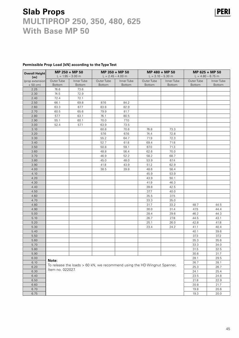
45
MP 250 + MP 50L = 1.95 – 3.00 m
MP 350 + MP 50L = 2.45 – 4.00 m
MP 480 + MP 50L = 3.10 – 5.30 m
MP 625 + MP 50L = 4.80 – 6.75 m
2.25 76.6 73.6
2.30 74.5 72.9
2.40 72.4 72.1
2.50 66.1 69.8 87.6 84.2
2.60 63.3 67.7 83.8 82.9
2.70 60.5 65.6 79.9 81.7
2.80 57.7 63.1 76.1 80.5
2.90 55.1 60.1 70.0 77.0
3.00 52.4 57.1 63.9 73.5
3.10 60.8 70.6 76.8 73.3
3.20 57.6 67.6 74.4 72.8
3.30 55.2 64.7 71.9 72.3
3.40 52.7 61.8 69.4 71.8
3.50 50.8 59.1 67.0 71.3
3.60 48.8 56.4 62.6 70.0
3.70 46.9 52.2 58.2 68.7
3.80 45.0 48.0 53.9 67.4
3.90 41.8 43.9 51.2 62.9
4.00 38.5 39.8 48.6 58.4
4.10 45.9 53.9
4.20 43.9 50.1
4.30 41.9 46.3
4.40 39.8 42.5
4.50 37.7 40.0
4.60 35.5 37.5
4.70 33.3 35.0
4.80 31.7 33.2 48.7 44.5
4.90 30.0 31.4 47.5 44.4
5.00 28.4 29.6 46.2 44.3
5.10 26.7 27.8 44.5 43.1
5.20 25.1 26.0 42.8 41.8
5.30 23.4 24.2 41.1 40.4
5.40 40.1 39.6
5.50 37.3 37.2
5.60 35.3 35.6
5.70 33.3 34.0
5.80 31.5 32.5
5.90 30.6 31.7
6.00 28.1 29.5
6.10 26.7 28.1
6.20 25.3 26.7
6.30 24.1 25.4
6.40 23.5 24.8
6.50 21.8 22.9
6.60 20.8 21.7
6.70 19.8 20.6
6.75 19.3 20.0
Slab PropsMULTIPROP 250, 350, 480, 625With Base MP 50
Permissible Prop Load [kN] according to the Type Test
Overall Height [m]
(prop extension
+ 50 cm)
Outer Tube
Bottom
Inner Tube
Bottom
Outer Tube
Bottom
Inner Tube
Bottom
Outer Tube
Bottom
Inner Tube
Bottom
Outer Tube
Bottom
Inner Tube
Bottom
Note:To release the loads > 60 kN, we recommend using the HD Wingnut Spanner,
Item no. 022027.

46
0.30 0.40 0.50 0.60 0.70 0.80
1
1 x GT 24
2
2 x VT 20
1
1 x GT 24
2
2 x VT 20
1
2 x GT 24
2
2 x VT 20
1
2 x GT 24
2
2 x VT 20
1
2 x GT 24
2
3 x VT 20
1
2 x GT 24
2
3 x VT 20
0 2.01 4.21 1.74 3.59 1.57 3.14 1.45 2.80 1.36 2.60 *1.29 *1.85
0.20 2.05 4.56 1.91 3.30 1.77 2.69 1.64 1.95 *1.35 *1.42 *1.02 *1.07
0.25 1.83 4.00 1.71 2.51 1.62 2.36 1.55 1.77 *1.23 *1.29 *0.94 *0.98
0.30 1.77 3.58 1.66 2.34 1.58 2.10 1.51 1.61 *1.13 *1.19 *0.86 *0.90
0.35 1.71 3.30 1.62 2.06 1.54 1.88 1.40 1.45 *1.04 *1.09 *0.77 *0.83
BeamsBeam Formwork UZ
Permissible width of influence [m] for UZ Beam Bracket 40 depending on the beam depth and slab thickness
d = Slab Thicknessh = Beam Depth
The max. deflection is l/500
*) vertical timber in the UZ Beam Bracket 40
10 x 8 cm! (instead of 8 x 8 cm)
The above values relate to the load-
bearing capacity of the UZ Beam
Bracket 40, the vertical 8 x 8 cm timber
and the secondary beams as they are
shown on the drawings.
Depending on the formlining used,
additional secondary beams may be
needed.
Separate structural calculations must
be provided to show that the sub-struc-
ture can carry all resulting loads.
The equivalent load (V/100) acting
horizontally and the pressures arising
on one side (e.g. the edge beam) are to
be accommodated by suitable means
provided by the contractor.
Side form with 1 or 2 GT 24 girders
(vertical)
dh
Side form with 2 or 3 VT 20 girders
(horizontal)
dh
Packing of the beam soffit form
dh
Version 1:
Version 2:
Version 3:
Slab Thickness
d [m]
Beam Depth h [m]
VersionVersionVersionVersionVersionVersion

47
0.20 0.25 0.30 0.35
0 3.27 3.27 3.27 3.27 2.82 2.86 2.86 2.86 1.63 2.60 2.60 2.60 0.97 2.21 1.69 1.90
0.20 1.19 2.75 2.05 1.88 0.71 1.64 1.24 1.32 0.45 1.02 0.79 0.99 - 0.69 0.54 0.76
0.25 1.07 2.46 1.84 1.63 0.61 1.39 1.06 1.16 0.39 0.88 0.68 0.87 - 0.60 0.47 0.67
0.30 0.93 2.15 1.61 1.43 0.54 1.23 0.94 1.03 - 0.77 0.60 0.78 - 0.53 0.41 0.60
0.35 0.82 1.89 1.41 1.28 0.47 1.08 0.83 0.92 - 0.69 0.53 0.69 - 0.47 - 0.54
0.40 0.73 1.69 1.26 1.14 0.42 0.96 0.73 0.83 - 0.62 0.48 0.63 - 0.42 - 0.49
0.40 0.50 0.60
0 0.62 1.41 1.09 1.40 - 0.68 0.53 0.83 - - - 0.54
0.20 - 0.49 - 0.60 - - - 0.40 - - - -
0.25 - 0.43 - 0.53 - - - - - - - -
0.30 - - - 0.48 - - - - - - - -
0.35 - - - 0.44 - - - - - - - -
0.40 - - - 0.40 - - - - - - - -
BeamsStopend Angle AW
Permissible width of influence [m] for Stopend Angle AW depending on the slab thickness, beam depth and type of fixing
– nail with 8 nails Ø 3.1 mm
(6 at the front and 2 at the back)
* Using the Guardrail Post AW on
SKYDECL panels is not permissible.
1. Stopend for Slab Formwork
dh
h
h
2. Slab with Edge Beam 3. Slab with T-Beam
Separate structural calculations must
be provided to show that the sub-struc-
ture can carry all resulting loads. The
equivalent load (V/100) acting horizon-
tally and the pressures arising on one
side (e.g. the edge beam) are to be
accommodated by suitable means
provided by the contractor.
Height of Side Formwork h [m]
Sub- Structure
Sla
b T
hic
knes
s d
[m
]
Height of Side Formwork h [m]
Sub- Structure
Sla
b T
hic
knes
s d
[m
]
nailed to clamping nailed to clamping nailed to clamping nailed to clamping
Formlining 21 mm
Timber Girder
Timber Girder
Formlining 21 mm
Timber Girder
Timber Girder
Formlining 21 mm
Timber Girder
Timber Girder
Formlining 21 mm
Timber Girder
Timber Girder
nailed to clamping nailed to clamping nailed to clamping
Formlining 21 mm
Timber Girder
Timber Girder
Formlining 21 mm
Timber Girder
Timber Girder
Formlining 21 mm
Timber Girder
Timber Girder
SKYDECK*
SKYDECK* SKYDECK* SKYDECK*
SKYDECK* SKYDECK* SKYDECK*

MULTIFLEX Girder Slab Formwork
48
Item no. Weight kg
075100
075120
075150
075180
075210
075240
075270
075300
075330
075360
075390
075420
075450
075480
075510
075540
075570
075600
5.300
7.100
8.900
10.600
12.400
14.200
15.900
17.700
19.500
21.200
23.000
24.800
26.600
28.300
30.100
31.900
33.600
35.400
Girders GT 24Girder GT 24, l = 0.90 mGirder GT 24, l = 1.20 mGirder GT 24, l = 1.50 mGirder GT 24, l = 1.80 mGirder GT 24, l = 2.10 mGirder GT 24, l = 2.40 mGirder GT 24, l = 2.70 mGirder GT 24, l = 3.00 mGirder GT 24, l = 3.30 mGirder GT 24, l = 3.60 mGirder GT 24, l = 3.90 mGirder GT 24, l = 4.20 mGirder GT 24, l = 4.50 mGirder GT 24, l = 4.80 mGirder GT 24, l = 5.10 mGirder GT 24, l = 5.40 mGirder GT 24, l = 5.70 mGirder GT 24, l = 6.00 m
L 918
1214
1510
1806
2102
2398
2694
2990
3286
3582
3878
4174
4470
4766
5062
5358
5654
5950
311 296
163 296
28
80
6012
060
240
L

MULTIFLEX Girder Slab Formwork
49
Item no. Weight kg
028870 5.430 Lowering Head 20/24, galv.For tilt-resistant support of one or two GT 24 or
VT 20 Girders.
Lowering range 4 cm.
NoteRequired hole diameter of the prop end plate
Ø 40 mm.
Girder overlap on both sides minimum 16.3 cm for
GT 24 and 15 cm for VT 20.
1942
1013
6
210
12
240
170
074990
074905
074910
074890
074920
074930
074940
074950
074960
074970
074980
8.560
12.700
14.460
15.640
17.110
19.470
21.240
23.010
26.550
28.910
34.810
Girders VT 20K with Steel CapGirder VT 20K, l = 1.45 mGirder VT 20K, l = 2.15 mGirder VT 20K, l = 2.45 mGirder VT 20K, l = 2.65 mGirder VT 20K, l = 2.90 mGirder VT 20K, l = 3.30 mGirder VT 20K, l = 3.60 mGirder VT 20K, l = 3,90 mGirder VT 20K, l = 4.50 mGirder VT 20K, l = 4.90 mGirder VT 20K, l = 5.90 m
L 1445
2150
2450
2650
2900
3290
3590
3890
4490
4900
5900

MULTIFLEX Girder Slab Formwork
50
Item no. Weight kg
027990 0.150 Bolt Ø 14 x 107, galv.For different connections.
107
129
26Ø
Ø14
018060 0.030
Accessories
Cotter Pin 4/1, galv.
028660
028670
1.040
0.936
Clawheads 16/20, galv.Clawhead 16/20 S, galv.Clawhead 16/20, galv.With or without self-locking coupling.
For positioning intermediate props on the VT 20
girder without nailing.
NoteRequired hole diameter of the prop end plate
Ø 40 mm.
140
Ø10
443
161
80
028890
028880
1.650
1.540
Clawheads 24, galv.Clawhead 24 S, galv.Clawhead 24, galv.With or without self-locking coupling. For posi-
tioning intermediate props on the GT 24 Girder
without nailing.
NoteRequired hole diameter of the prop end plate
Ø 40 mm.
280
6416
13
Ø10
80
028680
027890
3.190
3.080
Crossheads 20/24, galv.Crosshead 20/24 S, galv.Crosshead 20/24, galv.With or without self-locking coupling.
For tilt-resistant support of one or two GT 24 or
VT 20 Girders.
NoteRequired hole diameter of the prop end plate
Ø 40 mm.
Girder overlap on both sides minimum 16.3 cm for
GT 24 and 15 cm for VT 20.
240
170
191
86
210
12

MULTIFLEX Girder Slab Formwork
51
Item no. Weight kg
107152 5.810 Tripod PEP Ergo, galv.Erection aid for PEP Ergo Slab Props with
Ø 44 – 64 mm.
NoteOnly use as erection aid!
639
028000 9.170 Universal Tripod, galv.Erection aid for slab props with Ø 48 – 120 mm
and 120 x 120 mm. Can also be used in combina-
tion with MULTIPROP MP slab props and all slab
props with Base MP 50.
NoteOnly use as erection aid!
800
028590 0.568 Tension Strap 16-25, galv.For mounting 2 GT 24 or VT 20 Girders on the
Cross Forkhead and Head Spindle TR 38 and on
the Crosshead 20/24 or 20/24S.
210
110
270
SW 19
018060 0.030 Cotter Pin 4/1, galv.
Ø4

MULTIFLEX Girder Slab Formwork
52
Item no. Weight kg
103434
103429
38.500
45.300
Pallets RP-2, galv.Pallet RP-2 80 x 120, galv.Pallet RP-2 80 x 150, galv.For stacking and transportation of formwork and
scaffolding components.
NoteFollow Instructions for Use!
Technical DataPermissible load-bearing capacity 1.5 t.
1200 / 1500
1080 / 1380
853 60
0
100
800
680
027790 2.460 Brace Clamp HL, galv., 76 – 120 mmFor assembly of 3 x 15 cm stiffening boards at
slab props Ø 76 – 89 mm and 100 x 100 mm to
120 x 120 mm.
210
239
40
027940 1.840 Brace Clamp, galv., 48 – 76 mmFor assembly of 3 x 15 cm stiffening boards at
slab props Ø 48 – 76 mm.
210
400
186
40

MULTIFLEX Girder Slab Formwork
53
Item no. Weight kg
116292 4.730 Guardrail Post HSGP-2As guardrail for different systems.
120
100
1300
40
101290 5.670 Guardrail Holder GT 24 / VT 20For assembling a guardrail to GT 24 and VT 20
Girders.
Complete with1 pc. 018060 Cotter Pin 4/1, galv.
1 pc. 105400 Pin Ø 20 x 140, galv.
117
32Ø2132
81
116292
061260
4.730
6.150
Accessories
Guardrail Post HSGP-2 Guardrail Post SGP
070740 2.980 Erection Bar GT/VT, galv.For shuttering of MULTIFLEX with GT 24 or
VT 20 Girders.
190
1711
8
10
027930 3.060 Assembly Bar 24, galv.For shuttering of MULTIFLEX with GT 24 Girders.
49
920
Ø34

MULTIFLEX Girder Slab Formwork
54
Item no. Weight kg
018280 1.000 Double Head Nail, l = 65 mm NoteDelivery unit: carton with 1000 pieces.
Ø3,1
018290 0.098 Framing Clip, galv.For connecting crossed timbers or girders.
For either right or left handling.
10
170 10
170
33 33
3
Ø4,8
018280 1.000
Accessories
Double Head Nail, l = 65 mm
117326
117327
19.700
10.500
Side-Mesh-Barrier PMBSide-Mesh-Barrier PMB 260Side-Mesh-Barrier PMB 130
Technical DataMaximum distance with side-mesh-barrier:
PMB 260 max. 2.40 m, PMB 130 max. 1.20 m.
2608 / 1308
1097
127
061260 6.150 Guardrail Post SGPAs guardrail for different systems.
120
1438
1768
433
433

MULTIFLEX Girder Slab Formwork
55
Item no. Weight kg
035500 72.800 Stripping Cart, AluMobile working scaffold. Height-adjustable in
25-cm-increments. Platform height max. 2.00 m.
NoteFollow Instructions for Use!
Technical DataPermissible load 100 kg/m2.
1800
303

MULTIFLEX Girder Slab Formwork
56
Item no. Weight kg
116614 0.537 Flexclip GT/GTFor connecting girders GT 24 / GT 24.
70
220
81
102031 363.000 Stripping Cart ASW 465, compl.Mobile working scaffold. Height-adjustable in
30-cm-increments. Platform height max. 4.65 m.
Packed in:
Ring Pallet USP 104 Item no. 100678, with
Lashing Strap 25 x 5750 Item no. 100707 (x 1)
and Scaffold Tube Steel L = 1000 Item no. 100706
(x 6).
Complete with1 pc. 102025 Folding Base Unit 160/190 ASW
6 pc. 102035 Vertical Frame 70/90 ASW
6 pc. 102034 Vertical Frame 70/120 ASW
2 pc. 102026 Entry Platform 190 ASW
1 pc. 102030 Toe-Board Set 70/190 ASW
4 pc. 102027 Double Guardrail 190 ASW
3 pc. 102028 Diagonal Brace 210 ASW
2 pc. 102029 Horizontal Brace 190 ASW
12 pc. 102807 Ballast 10 kg ASW
2 pc. 103040 Lateral complete ASW
1 pc. 102587 Center part ASW galv.
NoteFollow Instructions for Use!
Technical DataPermissible load 100 kg/m2.
2360 1100
110

MULTIFLEX Girder Slab Formwork
57
Item no. Weight kg
117574 4.730 Distance Device MF-PlusFor placing, positioning on given distance and
aligning the formwork girders at the MULTIFLEX
System, as well as assembling the Flexclips.
2044
894
400
117575 0.178 Fixing Tool MF, galv.For assembling Flexclips onto the formwork
girders.
17 22
116596 0.467 Flexclip VT/VTFor connecting girders VT 20 / VT 20.
70
180
81
116605 0.493 Flexclip GT/VTFor connecting girders GT 24 / VT 20.
70
200
82

Beam Formwork System Components UZ, AW
58
Item no. Weight kg
065065 10.000 UZ Beam Width Adjustment Bar 129For use with UZ Beam Bracket 40. For beam width
max. 90 cm. Beam width more than 90 cm 2 or
more of the UZ Beam Width Adjustment Bars 129
to be connected.8
21
Ø14 Ø7
065057 7.060 UZ Beam Width Adjustment Bar 80For use with UZ Beam Bracket 40. For beam width
max. 40 cm. Beam width more than 40 cm 2 or
more of the UZ Beam Width Adjustment Bars 80
to be connected.
967
821
Ø7 Ø14
065056 11.300 UZ Beam Bracket 40For forming beams up to 80 cm high.
With captive Hook Tie and Wingnut Counterplate.
NotePermissible load: see PERI Design Tables.
440
66
0
84 1
Ø7
Ø7
Ø17

Beam Formwork System Components UZ, AW
59
Item no. Weight kg
065072 3.270 AW Clamp 8 – 10For clamping the AW Slab Stopend Angle to
girders or timbers with 8 – 10 cm thickness.
With captive Triple Wingnut.
279
132 27
90
065071 7.410 AW Handrail PostFor assembling the guardrail on the Slab Stopend
Angle AW. Secure rear end with nails.
77200
1439
67
065058 8.650 UZ Beam Yoke Waler 100For carrying one or two GT 24 Girders per side
along with additional support.
1000
6012
0
Beam Formwork System Components UZ, AW
60
Item no. Weight kg
126299 0.466 Plastic Slab Stopend Angle NoteSee data sheet!
80
203
302
065070 1.670 AW Slab Stopend AngleFor forming stopends for slabs and to form
beams.
NotePermissible load: see PERI Design Tables.
400
240
0
68
86
065075 1.750 AW BracketAs filler for the AW Slab Stopend Angle.
For height adjustment of side girder.
140 67
240
m40
max
220

61

2
1
3
4
5
6
9
11
12
1316
17
18
19
20
22
21
24
2829
30
32
33
34
38
41
42
46
48
52
44
53
60
62
02 PERI S.A.S.
77109 Meaux Cedex
www.peri.fr
03 PERI AG
8472 Ohringen
www.peri.ch
04 PERI S.A.U.
28110 Algete - Madrid
www.peri.es
05 N.V. PERI S.A.
1840 Londerzeel
www.peri.be
06 PERI Holding B.V.
5480 AH-Schijndel
www.peri.nl
07 PERI Formwork Systems, Inc.
Elkridge, MD 21075
www.peri-usa.com
08 PT Beton Perkasa Wijaksana
Jakarta 10210
www.peri.com
09 PERI S.p.A.
20060 Basiano
www.peri.it
10 PERI Japan K.K.
Tokyo 103-0015
www.perijapan.jp
11 PERI Ltd.
Rugby, CV23 0AN
www.peri.ltd.uk
12 PERI Kalip ve Iskeleleri Sanayi
ve Ticaret Ltd.
Esenyurt / İstanbul 34510
www.peri.com.tr
13 PERI Kft.
1181 Budapest
www.peri.hu
14 PERI Formwork Malaysia Sdn. Bhd.
43300 Seri Kembangan,
Selangor Darul Ehsan
www.perimalaysia.com
15 PERI Asia Pte Ltd
Singapore 387355
www.periasia.com
16 PERI Ges.mbH
3134 Nußdorf ob der Traisen
www.peri.at
17 PERI spol. S r.o.
252 42 Jesenice u Prahy
www.peri.cz
18 PERI Danmark A/S
2670 Greve
www.peri.dk
19 PERI Suomi Ltd. Oy
05460 Hyvinkää
www.perisuomi.fi
20 PERI Norge AS
3036 Drammen
www.peri.no
21 PERI Polska Sp. z o.o.
05-860 Płochocin
www.peri.com.pl
22 PERIform Sverige AB
30262 Halmstad
www.periform.se
23 PERI (Korea) Ltd.
Seoul 06243
www.perikorea.com
24 Pericofragens Lda.
2790-326 Queijas
www.peri.pt
25 PERI S.A.
B1625GPA Escobar – Bs. As.
www.peri.com.ar
26 PERI Formas e
Escoramentos Ltda.
Vargem Grande Paulista – SP
www.peribrasil.com.br
27 PERI Chile Ltda.
Colina, Santiago de Chile
www.peri.cl
28 PERI România SRL
077015 Baloteşti
www.peri.ro
29 PERI Agency
2000 Maribor
www.peri.com
30 PERI spol. s. r.o.
903 01 Senec
www.peri.sk
31 PERI Australia Pty. Ltd.
Glendenning NSW 2761
www.periaus.com.au
32 PERI AS
76406 Saku vald
Harjumaa
www.peri.ee
33 PERI Hellas Solely Owned Ltd.
194 00 Koropi
www.perihellas.gr
34 PERI SIA
2118 Salaspils novads, Rigas rajons
www.peri-latvija.lv
35 PERI (L.L.C.)
Dubai U.A.E.
www.perime.com
36 PERI Formwork Systems, Inc.
Bolton, ON – L7E 1K1
www.peri.ca
01 Germany PERI GmbH Rudolf-Diesel-Strasse 19
89264 Weissenhorn
www.peri.com
France
Switzerland
Spain
Belgium/Luxembourg
Netherlands
USA
Indonesia
Italy
Japan
United Kingdom/Ireland
Turkey
Hungary
Malaysia
Singapore
Austria
Czech Republic
Denmark
Finland
Norway
Poland
Sweden
Korea
Portugal
Argentina
Brazil
Chile
Romania
Slovania
Slovakia
Australia
Estonia
Greece
Latvia
United Arab Emirates
Canada
PERI International

8
10
1415
23
67
68
31
35
3739 40
43
44
45
47
50 51
5854
70
69
57
5659 55
64
63
65
7
25
26
66
27
36
49
61
62
63
37 PERI Lebanon Sarl
90416 – Jdeideh
38 PERI UAB
02300 Vilnius
www.peri.lt
39 PERI S.A.U.
Tanger
www.peri.ma
40 PERI Formwork
Engineering Ltd.
Rosh Ha‘ayin, 48104
www.peri.co.il
41 PERI Bulgaria EOOD
1839 Sofia
www.peri.bg
42 Armar ehf.
220 Hafnarfjörður
www.armar.is
43 TOO PERI Kazakhstan
050000 Almaty
www.peri.kz
44 OOO PERI
142407, Noginsk District
www.peri.ru
45 PERI (Pty) Ltd
7600 Stellenbosch
www.peri.co.za
46 TOW PERI
07400 Brovary
www.peri.ua
47 Egypt Branch Office
11341 Nasr City /Cairo
www.peri.com.eg
48 PERI – Oplate d.o.o.
22310 Šimanovci
www.peri.rs
49 PERI Cimbras y Andamios,
S.A. de C.V.
Estado de México, Huehuetoca
www.peri.com.mx
50 PERI Repesentative Office
Baku
www.peri.com.tr
51
PERI Kalıp ve İskeleleri
Aşgabat
www.peri.com.tr
52 IOOO PERI Belarus
220100 Minsk
www.peri.by
53 PERI oplate i skele d.o.o.
10 250 Luöko-Zagreb
www.peri.com.hr
54 PERI (India) Pvt Ltd
Mumbai – 400064
www.peri.in
55 PERI GmbH - Jordan
11947 Amman
www.peri.com
56 PERI Kuwait W.L.L.
13011 Kuwait
www.peri.com.kw
57 PERI Saudi Arabia Ltd.
21463 Jeddah
www.peri.com.sa
58 PERI Qatar LLC
P.O.Box: 31295 - Doha
www.peri.qa
59 Sarl PERI
Kouba 16092, Alger
www.peri.com
60
PERI Representative Office
Tirane
www.peri.com.tr
61 PERI Peruana S.A.C.
Villa El Salvador, Lima
www.peri.com.pe
62 PERI Panama Inc.
0832-00155 Panama City
www.peri.com.pa
63 Pericofragens, Lda.
Luanda
www.peri.pt
64 PERI Nigeria Ltd.
Lagos
www.peri.ng
65 PERI (L.L.C.)
Muscat
www.perime.com
66 PERI S.A.S. Colombia
Briceño, Cundinamarca
www.peri.com.co
67 PERI-Asia Philippines, INC.
Makati City
www.peri.com.ph
68 PERI (Hong Kong) Limited
Hong Kong SAR, PRC
www.perihk.com
69 PERI (Pty.) Ltd.
Windhoek
www.peri.na
70 PERI (Pty.) Ltd.
Matola
www.peri.co.mz
Lebanon
Lithuania
Morocco
Israel
Bulgaria
Iceland
Kazakhstan
Russian Federation
South Africa
Ukraine
Egypt
Serbia
Mexico
Azerbaijan
Turkmenistan
Belorussia
Croatia
India
Jordan
Kuwait
Saudi Arabia
Qatar
Algeria
Albania
Peru
Panama
Angola
Nigeria
Oman
Colombia
Philippines
Hong Kong
Namibia
Mozambique

DE
en
12
| 2
015
3
ma
79
19
32
©
PE
RI
Gm
bH
The optimal System for every Project and every Requirement
PERI GmbHFormwork Scaffolding EngineeringRudolf-Diesel-Strasse 19
89264 Weissenhorn
Germany
Tel. +49 (0)7309.950-0
Fax +49 (0)7309.951-0
www.peri.com
System-Independent Accessories
Wall Formwork Column Formwork
Slab Formwork Climbing Systems Tunnel Formwork Bridge Formwork
Shoring Systems Facade ScaffoldConstruction Scaffold Industrial Scaffold
Access Protection Scaffold Services