Embed Size (px)
Citation preview

N RL REPORT 3886
MICROWAVE INSTRUMENTATION FORMULTIFREOUENCY ATTENUATION MEASUREMENTS
THROUGH PROPELLANT GASES
W. W. Balwanz, G. D. Morehouse,and
J. M. Headrick
February 13, 1952
Approved by:
*T O, Malcolm F. Gager, Head, Special Research BranchR. M. Page, Superintendent, Radio Division HlT
qr
NAVAL RESEARCH LABORATORYCAPTAN F. R, rURTH1, USN, DMIKORj WASHINGTON, D.C.
• APPROVED °FOR PUBLI
2Ram a, DISTRIBUTION
20061027011

r
U NO
CONTENTS
Abstract ivProblem Status ivAuthorization iv
INTRODUCTION 1
General Specifications 1Measurement System Features 1
RECORDING METHODS 8
MICROWAVE POWER SOURCES 9
PULSER, AMPLIFIER, AND DISPLAY EQUIPMENT 10
Master Oscillator 10Group-Pulse Generator 12Three-Channel Pulse Amplifier 13Transmitter Monitor 14Mixer-Amplifier 14Pulse Divider 15Display Unit 16
TRAVELLING AIR GAP AND ASSOCIATED APPARATUS 17
Railway System 17Waveguide Power Feed 19Antenna System 19R-F, Detection, and Video Lines 22
CONCLUSIONS AND RECOMMENDATIONS 22
REFERENCES 24
APPENDIX - Schematic Diagrams 26
U iii
UNCLASSIFIED
UN CLASSIFIED
ABSTRACT
In studying electromagnetic propagation through -theexhaust flames of reaction motors, the need of improvedinstrumentation for determining the loss of energy in theflame was recognized. A system utilizing pulsed electro-magnetic energy at S-, X-, and K-Band frequencies on atime-sharing basis has been constructed and used in thefield to make such measurements. Lens antennas were usedto focus the energy within the flames and a traveling frameprovided a means of exploring the length of the flame. Datawas recorded on film at the rate of 32 readings per secondfor each frequency. This system is here described; themeasurements obtained will be given in a later report.
PROBLEM STATUS
This is an interim report; improvement on instru-mentation is continuing and further experimental work isplanned.
AUTHORIZATION
NRL Problem Rll-13RDB Project NR511-130
Manuscript submitted September 20, 1951
iv
UNCLASSIFIED
7-
MICROWAVE INSTRUMENTATION FORMULTIFREQUENCY ATTENUATION MEASUREMENTS
THROUGH PROPELLANT GASES
INTRODUCTION
General Specifications
Various phases of the problem of determining "Electromagnetic Wave Propagationthrough Propellant Gases" have previously been presented (1, 2, 3, 4,.5, 6, 7). Furtherexperiments were planned, and based on previous theoretical and experimental investi-gations, a method of instrumentation was established to concurrently determine at threedifferent frequencies losses of electromagnetic energy due to passage through a rocketmotor exhaust flame. The following general specifications for instrumentation wereestablished:
a. Three frequencies, one each in the S-, 7-, and K-Bands, were to be usedeither simultaneously or on a time-sharing basis.
b. The electromagnetic radiations for the three frequencies were to befocused on a small area in the propellant gases.
c. The complete antenna system was to be such that it could be movedcontinuously and automatically parallel to the axis of the propellantgases during an observation run.
d. The field intensities in the propellant gases were to be as low as possiblein order to minimize any disturbing influence on the gases, yet to be ofsufficient strength to allow measurements to a level of approximately 40 dbbelow the value observed in the absence of the heated gases.
e. An automatic recording system was to be provided.
f. Measurements were to be accurate to within ±1 db when operating in thestrong vibration field .produced by the larger rocket motors.
Such a system was constructed and was used to conduct experiments on the exhaustgases of rocket motors. It is the purpose of this report to describe the system used.Before describing the system used some of the requirements for the system and theirrelation to the methods chosen will be discussed.
Measurement System Features
Measurements of the losses attending electromagnetic waves as they passed througha flame were desired. The word "losses" as used here, (and often referred to as "attenuation"),
UNCLASSIFIED

UNCUSSIFIL
2 NAVAL RESEARCH LABORATORY
means losses due to reflection, refraction, and absorption phenomena. No attempt wasmade in the system to be described to separate these phenomena.
Where large energy losses occur in a flame, it is extremely important to reduce thesignal traveling between antennas by extraneous path (reflections from ground, etc.) to aminimum. For example, if the signal were attenuated 20 db in the flame, the signal travel-ing between antennas by any path, other than directly through the flame, must be much lessthan one percent of the total energy received under the no-flame conditions in order toobtain a reasonable degree of measurement accuracy. Thus it was seen that extremelyhigh gain antennas would be required. Experimentally it was determined that the desireddirectivity could be achieved at microwave frequencies by means of lens antennas (6)placed close to the flame and focused on the center of the flame.
Theoretical considerations indicate that the attenuation is a function of the frequencyof the incident radiation. To investigate this phenomenon, three different frequencies wereselected, one each in the S-, X-, and K-Band regions. Ideally these should be measuredsimultaneously and along the same path through the flame.
It appeared impractical to construct a single antenna system that would handle the threefrequencies. Consequently, the essentially symmetrical radial characteristics of the flamewere utilized, and three pairs of antennas (one pair for each frequency) were arranged radi-ally around the flame, each antenna being focused on the center of the flame.
Previous experience had shown appreciable interference between signals when usedsimultaneously. Although this problem could be solved, it would involve more work thanappeared expedient. Further there appeared to be little loss in time-sharing of signals,since previous experience had shown that data could be repeated to within experimentalaccuracy on successive motor runs. Consequently a pulse system was selected, the pulsesof the three frequencies being synchronized but displaced from each other in time by approxi-mately 40 microseconds.
A system that would direct the electromagnetic energy through the flame transverseto the line of flow of gases appeared to be the best method available for restricting essen-tially all the energy along paths within the flame. A thorough investigation of the flame thenrequired that it be examined along its entire length. As a result, the radially mounted antennasystem was situated on a car which could be moved automatically along the length of the flameduring a single run of the reaction motor. The system was designed to give an independentreading of attenuation for each one-seventh inch interval along the length of the flame.
Previous experience had indicated that in order to obtain the desired accuracy mostof the electronic equipment had to be well isolated and built to stand the strong vibrationfield which exists in the immediate vicinity of a rocket motor flame. This was accomplishedby placing the transmitting equipment and the major part of receiving equipment in mobiletrucks and locating the trucks in an area of low noise field, the signals between trucks andthe antenna system being transmitted by means of waveguide and coaxial lines. Large lossesin the transmission lines between the transmitter truck and the transmitting antennas pre-sented no difficulty since relatively high power pulse-operated magnetrons were readilyavailable. The problem of coupling the rigid waveguide used for transmission of X- andK-Band signals to the moving antenna system was solved by utilizing rotary waveguidejoints.
Variable calibrated waveguide-type precision attenuators were installed in each receiv-ing system just ahead of the detector crystals in order to calibrate the complete system.
UNCLASSIFIE

NAVAL RESEARCH LABORATORY C
3
Since the long-time stability of such detectors is questionable, calibration was performedjust prior to and immediately following each run.
In order to keep the electromagnetic signal level within the flame as low as practical, r
and also to simplify the transmission-line problems, the detectors were mounted near thereceiving antennas. The X- and K-Band crystals were situated on the antenna mountingframe and the S-Band crystal within the coaxial line approximately 25 feet from thereceiving-horn throat. The rectified signalswere then fed through flexible cables to thepulser, amplifier, and display equipment.
The pulser, amplifier, and display equipment was utilized to initiate the pulses and toamplify and display the amplitude of the received signals on a cathode-ray tube. The result-ing signal traces were photographed with continuously moving roll film to provide a record-ing of the signal loss as a function of the position of the antenna system. This unit wasdesigned to record the amplitude of signals over the complete working range of the crystalsused, a range of approximately 60 decibels. (Under actual motor firing conditions the noiselevel limited measurements to a range of approximately 30 db.) The display unit also dis-played a monitor signal direct from the transmitters, thus giving a pulse-by-pulse incidentsignal reference to be compared with the output signals.
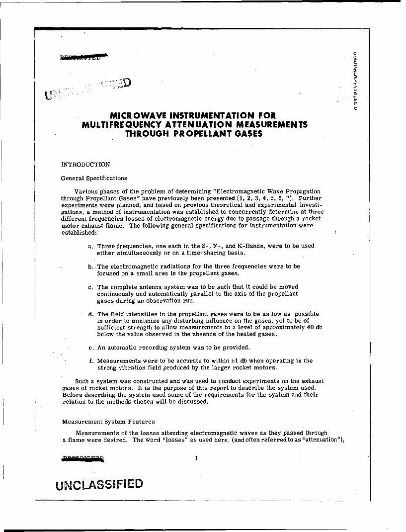
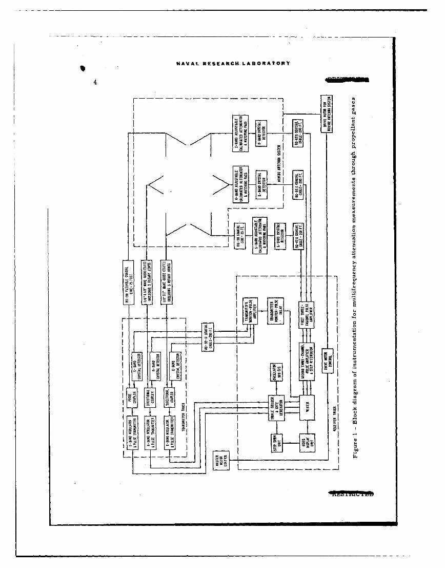
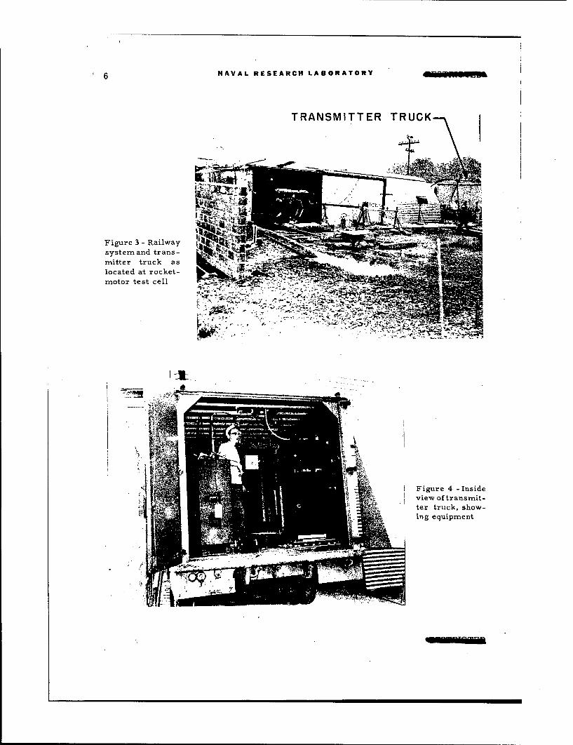
A block diagram of the electronic components of this system is shown on Figure 1.The antenna system on its movable platform is shown on Figures 2 and 3. The transmittertruck is shown on the extreme right of the latter figure. An inside view of the transmittertruck is shown on Figure 4. The receiver van and an interior view are shown in Figures5 and 6. This position of the receiver van was selected, with the building shown, Figure 5,between the truck and the reaction motor test cell, in order to reduce the noise level. Aview of the rotary joint system of hinging waveguide is shown in Figure 2.
Since the instrumentation for this system was designed for a particular display ofinformation and its recording, this phase will next be considered.
NAVAL RESEARC14 LABORATORY
4R
4"-
I r
L2L

NAVAL RESEARCH LABORATORY5
c)
Ul
c.)
*' 6 NAVAL RESEARCH LABORATORY
TRANSMITTER TRUCK
Figure 3 - Railway N -'z•
system and trans-mitter truck as -"
located at rocket-
motor test cell
'IL.
Figure 4 - Inside
view of transmit-ter truck, show-ing equipment

NAVAL RESEARCH LABORATORY c
C
t;
Figure 5 - Location of receiver van (test cell containingrocket motor is behind Quonset hut)
Figure 6 - View of equipment in receiver van (only the first tworacks were utilized for the multifrequency attenuation measurements)
S 8 NAVAL RESEARCH LABORATORY
RECORDING METHODS
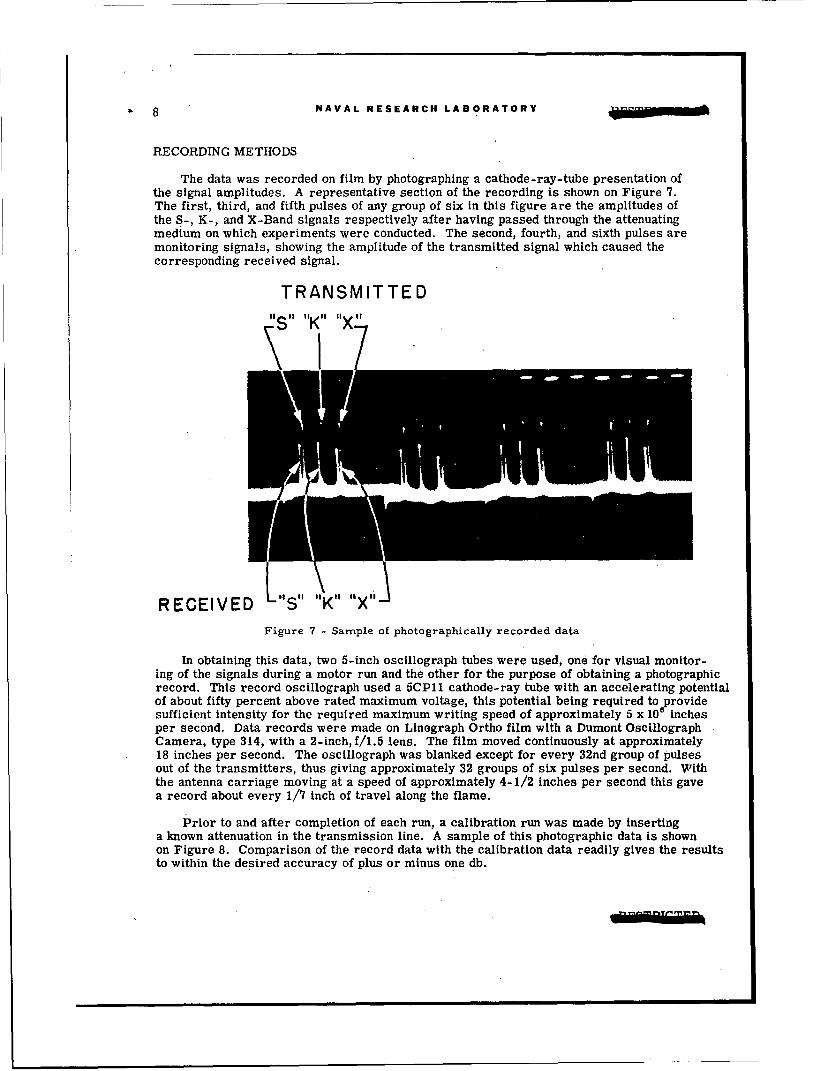
The data was recorded on film by photographing a cathode-ray-tube presentation ofthe signal amplitudes. A representative section of the recording is shown on Figure 7.The first, third, and fifth pulses of any group of six in this figure are the amplitudes ofthe S-, K-, and X-Band signals respectively after having passed through the attenuatingmedium on which experiments were conducted. The second, fourth, and sixth pulses aremonitoring signals, showing the amplitude of the transmitted signal which caused thecorresponding received signal.
TRANSMITTEDii a1 ''Kn '1X 11
R E C E IV E D 8'"S ol 1"K "1 "IX "
Figure 7 - Sample of photographically recorded data
In obtaining this data, two 5-inch oscillograph tubes were used, one for visual monitor-ing of the signals during a motor run and the other for the purpose of obtaining a photographicrecord. This record oscillograph used a 5CPll cathode-ray tube with an accelerating potentialof about fifty percent above rated maximum voltage, this potential being required to providesufficient intensity for the required maximum writing speed of approximately 5 x 10 inchesper second. Data records were made on Linegraph Ortho film with a Dumont OscillographCamera, type 314, with a 2-inch, f/1.5 lens. The film moved continuously at approximately18 inches per second. The oscillograph was blanked except for every 32nd group of pulsesout of the transmitters, thus giving approximately 32 groups of six pulses per second. Withthe antenna carriage moving at a speed of approximately 4-1/2 inches per second this gave"a record about every 1/7 inch of travel along the flame.
Prior to and after completion of each run, a calibration run was made by inserting"a known attenuation in the transmission line. A sample of this photographic data is shownon Figure 8. Comparison of the record data with the calibration data readily gives the resultsto within the desired accuracy of plus or minus one db.

NAVAL RESEARCH LABORATORY 9 C
r
C,.
0I 2 .3
INSERTION LOSS-DECIBELS
Figure 8 - Sample of calibration data
MICROWAVE POWER SOURCES
The S-, X-, and K-Band transmitters, modulators, and associated power supplies weremounted in a separate truck, Figure 4. The keying signal of 960 pulses per second was fedinto the respective equipments by cables from the pulser, amplifier, and display equipment.
A Model 12 modulator and power supply (built by Wholesale Radio Laboratories, Boston,Mass.) was used to drive a 2J32 magnetron for the S-Band signal of one microsecond pulselength, This complete unit, shock-mounted to the truck floor, is shown in Figure 9. AnotherModel 12 modulator and power supply (built by Henry Dormitzer Electronics, Newton, Mass.)was used to drive a 2J31 magnetron to supply the K-Band signal of one-half microsecondpulse length. This complete unit is shown, shock-mounted to the truck floor, by Figure 10.
Figure 9 = S-Band transmitter, Figure 10 K-Band transmitter,modulator, and power supply modulator, and power supply

10 NAVAL RESEARCH LABORATORY RESTRICTED
A type AM-44/CPN-6 modulator driver, type T-79/CPN-6 transmitter modulatorandtype PP-93/CPN-6 transmitter power supply (built by Galvin Manufacturing Corp.,Chicago, Ill.) was used to drive a type 2J55 magnetron to supply the X-Band signal ofone microsecond pulse length. The transmitter modulator Is shown on the left in Figure 4.
PULSER, AMPLIFIER, AND DISPLAY EQUIPMENT
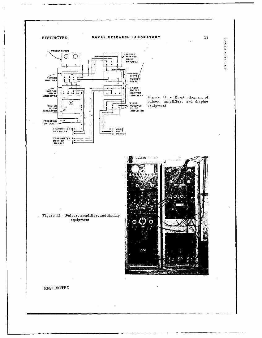
The group-pulse generator, amplifier, and display equipment was designed to keythree pulse-transmitters operating on different frequencies, and to amplify and displaycertain phenomena quasi- simultaneously.
The timing unit of the equipment is a group-pulse generator designed to producethree keying pulses, whose time displacements are continuously variable, and also togenerate a fixed trigger pulse that operates the sweep of the presentation unit. Simul-taneously with each keying pulse a gating pulse is generated. This gating pulse can beutilized to cut off two of the channels when displaying the pulses from the remainingchannel.
The display unit contains a sweep generator, a video amplifier, and two five-inchcathode-ray tubes. One cathode-ray tube provides a means for visual observation;the other, a means for photographic recording.
The composite-pulse signal is fed into the presentation unit from a mixer amplifierwhich provides one output from four separate inputs. Three input channels are alike,each containing a gating circuit and suitable amplifier; the fourth Is a simple amplifier.A switching arrangement is provided in the gated channels to enable a gated or nongatedmode of operation. All channels have individual gain controls and input pulse polarity-selection switch. The mixer section of this unit combines the signals of the four channelsinto a composite signal in one output channel.
A grouped-pulse signal is fed into the fourth channel from the transmitter monitorsection, which contains a mixer with three input channels and appropriate amplifiers.The monitoring pulses are obtained from crystal detectors located in the radio-frequencyportion of each of the three transmitters. Before the composite monitor signal is appliedto the fourth channel of the mixer amplifier unit, it must travel through a delay line toprovide good visual separation between each received and transmitted pulse.
The received-pulse amplifier is a three-channel, two-section unit with a continuousgain control and a step attenuator in each channel. The input connection to each channelcan be made directly to a terminated line from a crystal detector or to an additional low-level amplifier.
A block diagram, Figure 11, illustrates how the units are connected to make up thepulser, amplifier, and display equipment. Figure 12 shows a photograph of this equipment.
Master Oscillator
The master oscillator in this equipment determines the recurrence rate of all of thepulse and gate signals. and this rate of operation is determined chiefly by the power limi-tations of the lowest-powered magnetron. Originally the oscillator used was an audiooscillator (Hewlett-Packard Model 200A) set at approximately 960 cycles per second.
RESTRICTED
RESTRICTED NAVAL RESEARCH LABORATORY 11
PRESENTATION
R'ECEIVED eq p enOSCILLATOR
Figur lZ -Pulse, ampifierMandIispla
equiTmenS
RESTRICTED

12 NAVAL RESEARCH LABORATORY RESTRICTED
The output of this oscillator was fed into the shaping circuit in the group-pulse generator,which is described in the discussion of the latter unit. When used in the field, the videoportions of the equipment displayed a hum modulation pattern on the amplitude of themonitored and received pulses. Subsequently a synchronous oscillator was developed andincorporated into the equipment so as to make this hum modulation of minimum consequence.This latter oscillator takes the form of a frequency multiplier, multiplying sixty cycles tonine-hundred-sixty cycles in two multiplication steps.
The first multiplication is accomplished by applying a large amplitude sixty-cyclewave to a clipper tube and circuit to produce a squared or clipped wave. This signal Isapplied to the grid of a beam pentode whose plate circuit is an inductance-capacitanceparallel resonant circuit with a resonant frequency four times line frequency, or twohundred and forty cycles. A beam pentode tube was chosen because a large output couldbe obtained with the available input signal and the plate resistance of the tube will notappreciably lower the Q of the toroid inductance employed.
The output from the first multiplier circuit is coupled into a second clipper like thatof the first. This squared or clipped signal is fed into a second multiplier stage to bemultiplied four times. The output of this stage produces the desired nine-hundred-sixty-cycle frequency. The circuit for the second multiplier is the same as that for the first,except for differences in the value of the inductance and capacitance in the tuned circuit.
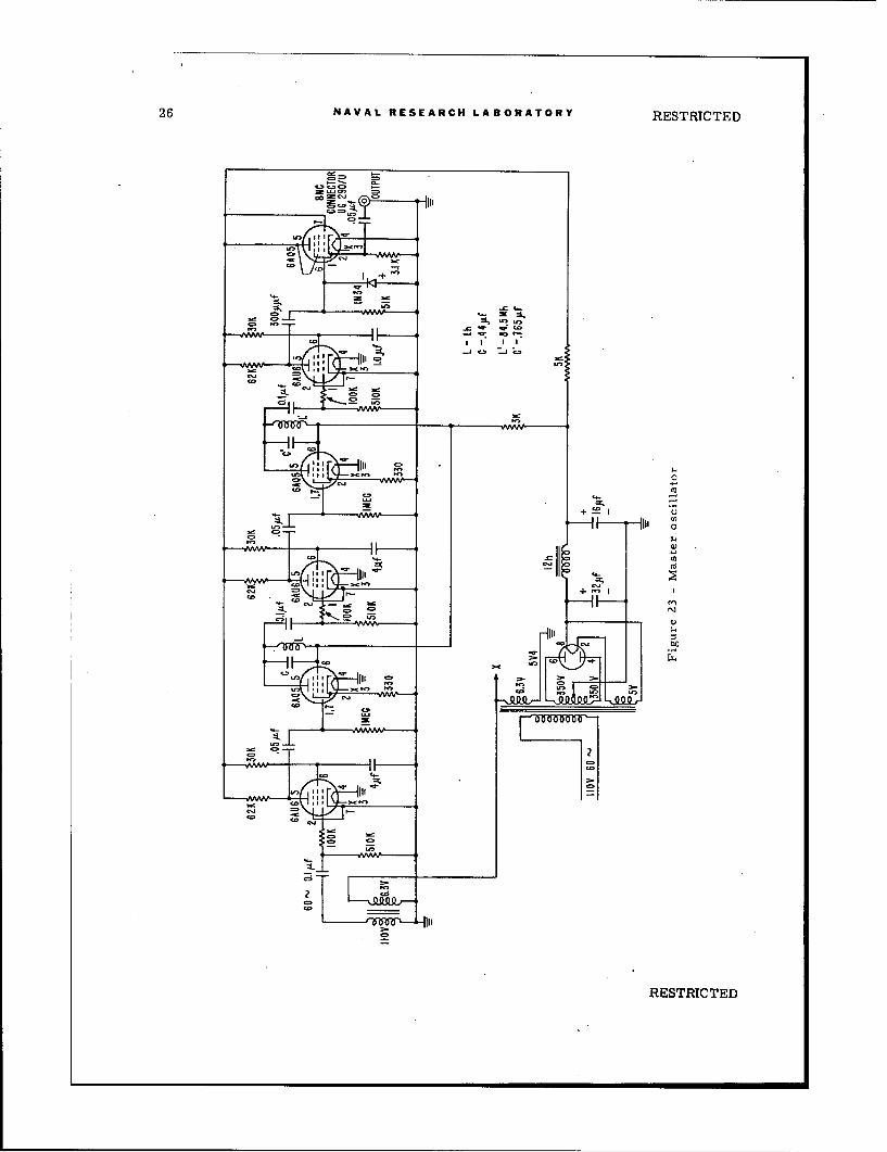
The nine-hundred-sixty-cycle signal is clipped in the same manner as in the previousclippers and is then differentiated in a diode differentiator circuit to produce positivepulses. These pulses are connected to external circuits through a cathode follower. Fig-ure 23 in the Appendix shows a detailed schematic diagram of the master oscillator systemdescribed.
Group-Pulse Generator
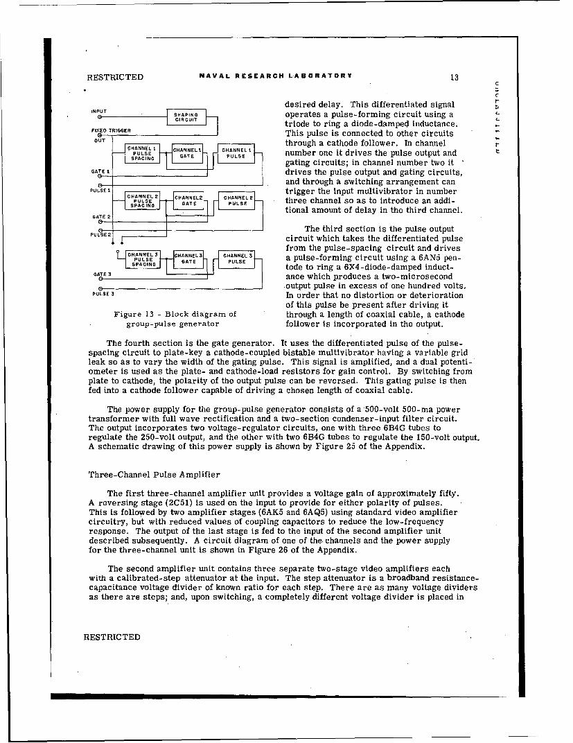
The group-pulse generator produces three keying pulses displaced from each otherin time, and simultaneously with each of these pulses, also produces a gating pulse. A fixedtrigger-pulse is additionally produced and occurs ahead of the first keying-pulse. Thetime displacement between the trigger pulses and the fixed pulse can be continuously varied.The group-pulse generator can be operated from a sine wave or pulse input of frequency upto one thousand cycles. Figure 13 is a block diagram and Figure 24 in the Appendix, aschematic diagram of the group-pulse generator.
This unit is composed of four separate sections; the first is a shaping circuit whichenables the use of a sine-wave source of frequency; the second, third, and fourth producethe keying and gating pulses.
The first section consists of two high-gain pentodes in a cascade clipper-circuit whichwill accept a sine-wave signal of large amplitude and produce square-wave output. Thisoutput is differentiated, and the positive pulse signal operates a pulse-forming circuit usinga triode-connected pentode to ring a diode-damped inductance. The pulse from this circuitis coupled to the input of each of the three channels through a cathode follower. It is alsobrought out to a jack for a fixed trigger which synchronizes the presentation unit.
The second section consists of the pulse-spacing circuits. The fixed trigger plate keysa multivibrator with a variable grid-leak resistor to introduce pulses up to two hundredmicroseconds long. This pulse is differentiated, the negative pulse being used to give the
RESTRICTED
RESTRICTED NAVAL RESEARCH LABORATORY 13C
C
desired delay. This differentiated signal rINPUT I•-
ISHAPING operates a pulse-forming circuit using a
triode to ring a diode-damped inductance.FIXED TRIGGERE This pulse is connected to other circuits
UT CHANNEL I CHANNEL through a cathode follower. In channel rPUANNELE number one it drives the pulse output and
gating circuits; in channel number two itGATEI tdrives the pulse output and gating circuits,
0 and through a switching arrangement canPULSEI ,trigger the input multivibrator in number
SAINGL GATE2 PUELSE three channel so as to introduce an addi-SPACN UEtional amount of delay in the third channel.
GATE 2
The third section is the pulse outputPUL.SE 2 circuit which takes the differentiated pulse
from the pulse-spacing circuit and drivesPULSECHA S a pulse-forming circuit using a 6AN5 pen-
tode to ring a 6X4-diode-damped induct-GATE 3ance which produces a two-microsecond
PS .output pulse in excess of one hundred volts.PULSE 3 In order that no distortion or deterioration
of this pulse be present after driving itFigure 13 - Block diagram of through a length of coaxial cable, a cathode
group-pulse generator follower is incorporated in the output.
The fourth section is the gate generator. It uses the differentiated pulse of the pulse-spacing circuit to plate-key a cathode-coupled bistable multivibrator having a variable gridleak so as to vary the width of the gating pulse. This signal is amplified, and a dual potenti-ometer is used as the plate- and cathode-load resistors for gain control. By switching fromplate to cathode, the polarity of the output pulse can be reversed. This gating pulse is thenfed into a cathode follower capable of driving a chosen length of coaxial cable.
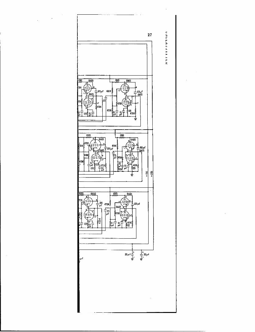
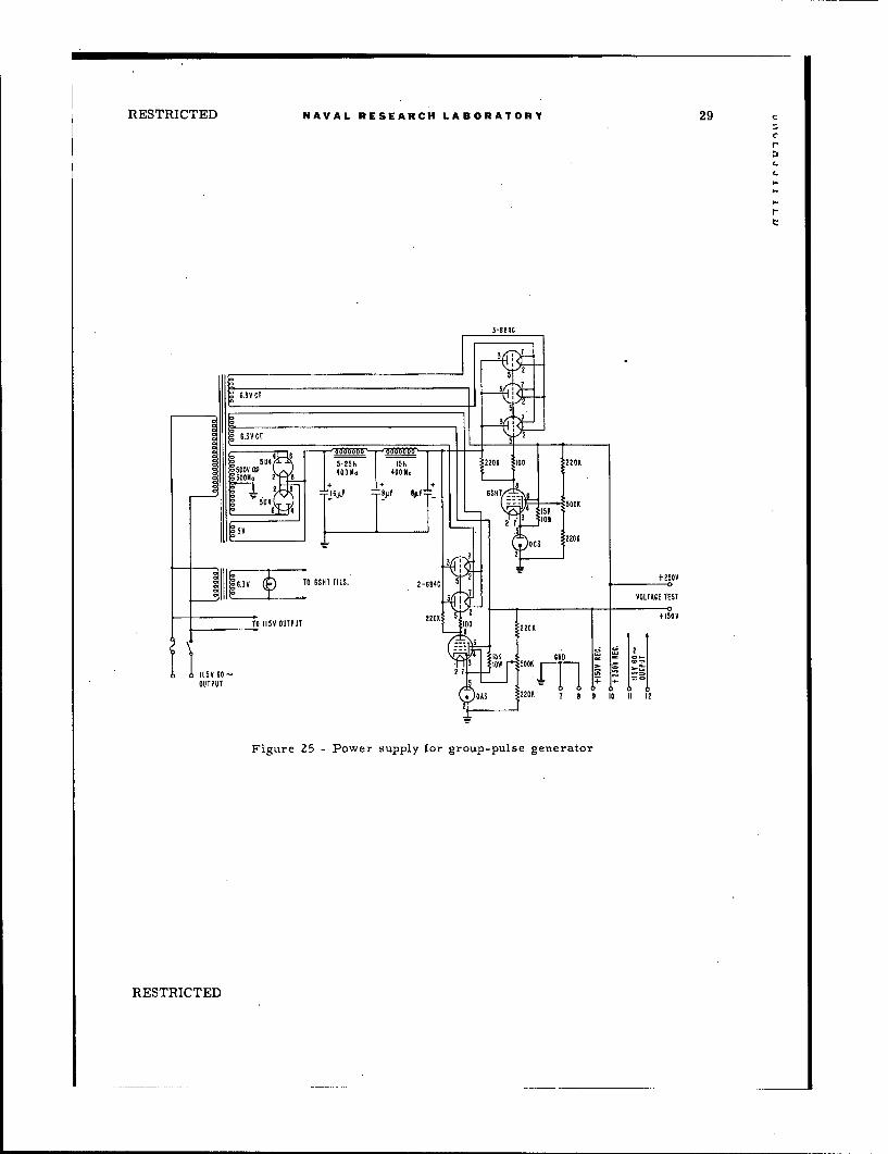
The power supply for the group-pulse generator consists of a 500-volt 500-ma powertransformer with full wave rectification and a two-section condenser-input filter circuit.The output Incorporates two voltage-regulator circuits, one with three 6B4G tubes toregulate the 250-volt output, and the other with two 6B4G tubes to regulate the 150-volt output.A schematic drawing of this power supply is shown by Figure 25 of the Appendix.
Three-Channel Pulse Amplifier
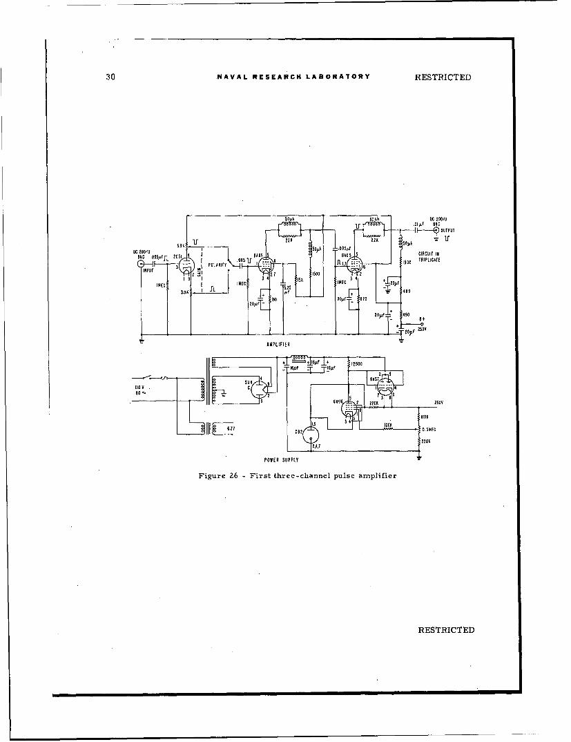
The first three-channel amplifier unit provides a voltage gain of approximately fifty.A reversing stage (2C51) is used on the input to provide for either polarity of pulses.This is followed by two amplifier stages (6AK5 and 6AQ5) using standard video amplifiercircuitry, but with reduced values of coupling capacitors to reduce the low-frequencyresponse. The output of the last stage is fed to the input of the second amplifier unitdescribed subsequently. A circuit diagram of one of the. channels and the power supplyfor the three-channel unit is shown in Figure 26 of the Appendix.
The second amplifier unit contains three separate two-stage video amplifiers eachwith a calibrated-step attenuator at the input. The step attenuator is a broadband resistance-capacitance voltage divider of known ratio for each step. There are as many voltage dividersas there are steps; and, upon switching, a completely different voltage divider is placed in
RESTRICTED
14 NAVAL RESEARCH LABORATORY RESTRICTED
the circuit. In the case of the first' step (or 1 to 1 step) there is a shunt parallel resistance-capacitance circuit to ground. This is in the circuit to enable additional multiplicationsthat can be equalized for broadband use to be placed ahead of the existing divider.
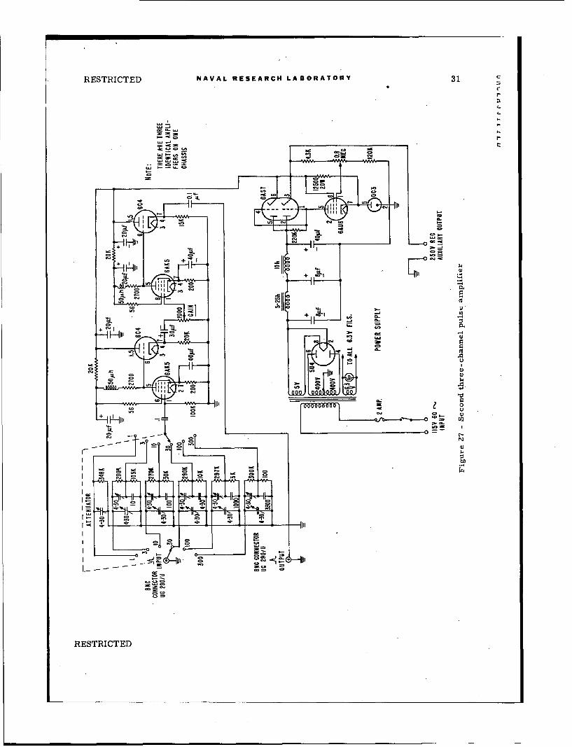
Each amplifier is two-stage, cathode-follower coupled with a continuously variablegain control at the grid of the second stage. Each of the two stages are alike, containinga pentode 6AK5 amplifier with a 6C4 triode cathode follower. The amplifiers are shieldedfrom each other to avoid crosstalk between channels, and decoupling of the plate supplyvoltage is employed to reduce hum. The power supply is voltage-stabilized to prevent anypossibility of amplitude change of signal due to change in voltage of the power source. Fig-ure 27 of the Appendix shows a schematic diagram of one representative amplifier channeland the power supply for all three channels.
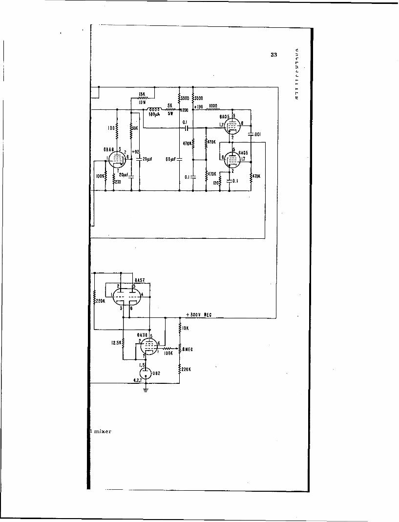
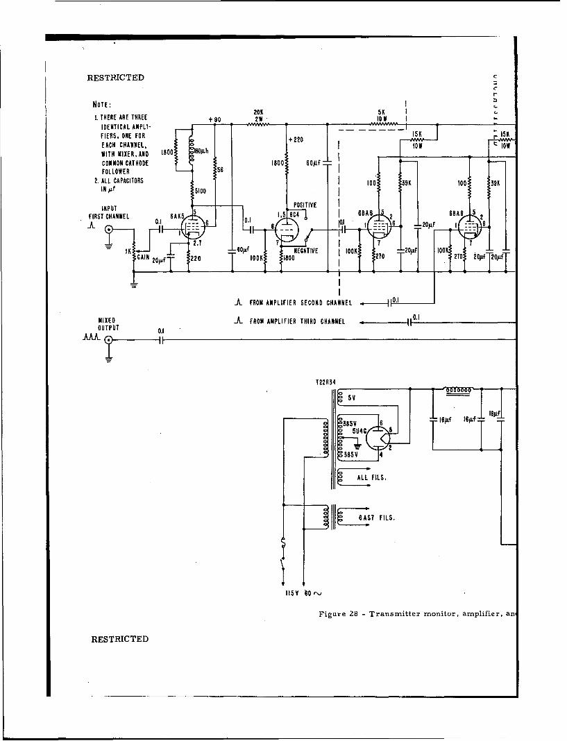
Transmitter Monitor
The transmitter monitor unit is one which amplifies the monitoring pulses from thethree individual transmitters and mixes these three channels into one output. The inputto each channel is arranged to accept pulses of either polarity from a cable connected tothe crystal detector. The gain control is a low-resistance potentiometer of such value asto minimize capacity loading of the crystal detector by the cable. If extremely long cablesare to be used, a cathode follower should be connected between the crystal detector and thelong cable. The signal from the Jain-control potentiometer is coupled into a 6AK5 pentodeamplifier and then into a 6C4 triode amplifier. A switching arrangement is placed in thecoupling circuit to the input of the mixer tube. This switch enables pulses of either polarityat the input to appear as positive pulses at the output of the mixer. The mixer circuit con-tains three remote-cutoff pentodes with the grid of each coupled to the external circuitsthrough a cathode follower. The external circuit of this unit is a delay line whose delay isapproximately 7 microseconds. This delay line is coupled to the monitor input channel Inthe mixer-amplifier unit, and displaces the monitor pulse from the received pulse, thusgiving three groups of pulse pairs on the presentation unit. The power supply requirementsare met by the use of a carefully designed voltage-stabilization circuit and by decoupling thedirect-voltage source into each channel.
Figure 28 of the Appendix shows the schematic of a representative single channel themixer section, and the power supply for the unit.
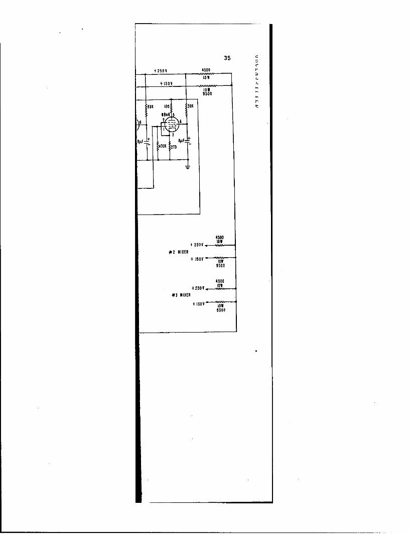
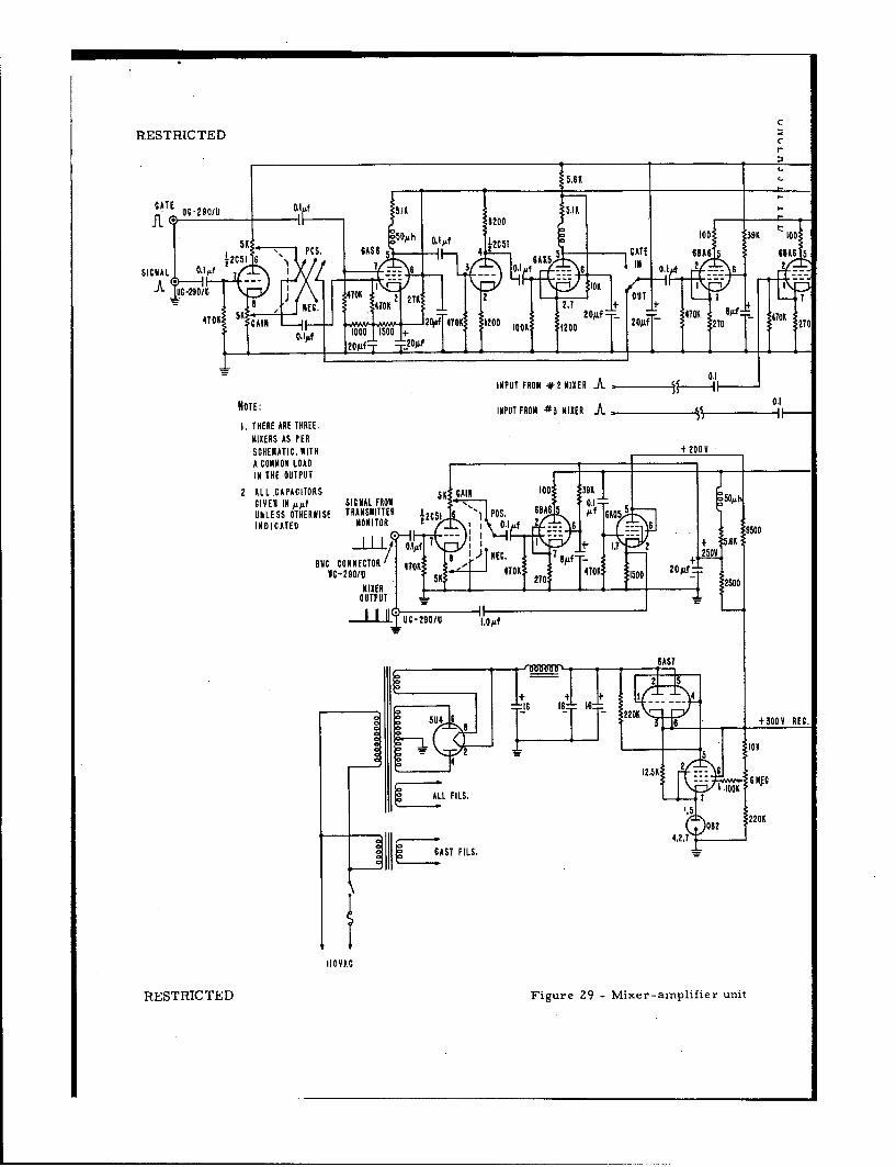
Mixer-Amplifier
The mixer-amplifier unit amplifies, gates, and mixes four separate input channels intoone output channel so as to enable presentation on the dual-tube presentation unit.
The input to each of the three signal channels is arranged to accept either a positiveor negative pulse signal but always present a positive pulse signal to the grid of the gatingtube. The gating circuit contains a 6AS6 tube chosen because of its particular controlproperties in the suppressor grid. The control grid is biased in such a way that the tubewould operate as a class-A amplifier, and the suppressor grid is biased for plate cutoff.At quiescence the screen grid is the only element in the tube that is conducting. If a pulsesignal comes to the grid there will be no signal at the plate, but If at the same time a gating-pulse signal occurs at the suppressor grid, then both signals will appear at the output. Theoutput from the gate stage is amplified through a triode and then a pentode stage that isbiased beyond cutoff. The bias on this pentode stage may be changed at will from the front
RESTRIC TED
RESTRICTED NAVAL RESEARCH LABORATORY 15
panel so as to cause the gating pulse (or pedestal) to appear or disappear. The subsequent
output is coupled into the grid of a mixer tube. 4
The mixer circuit contains four remote-cutoff pentodes 'with separate inputs to eachcontrol grid, and all plates connected to a common plate-load circuit. This in turn is fedinto the presentation unit through a cathode follower to minimize capacity loading fromthe interconnecting cable. Figure 29 of the Appendix shows the schematic of one amplifierchannel, the mixer channels, and the associated power supply.
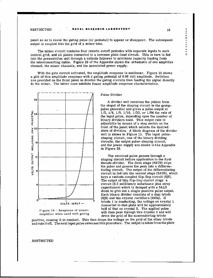
With the gate circuit activated, the amplitude response is nonlinear. Figure 14 showsa plot of this amplitude response with a gating pedestal of 0.06 volt amplitude. Switchesare provided on the front panel to disable the gating circuits thus feeding the signal directlyto the mixer. The latter case exhibits linear amplitude response characteristics.
Pulse Divider
A divider unit receives the pulses fromthe otuput of th.e shaping circuit in the group-pulse generator and gives a pulse output at
24 1/2, 1/4, 1/8, 1/16, 1/32, or 1/64 the rate ofcnthe input pulse, depending upon the number ofLU binary dividers used. This output rate is0a. adjustable by means of a step switch on the
> 2C front of the panel which selects the desiredt state of division. A block diagram of the divider
unit is shown in Figure 15. The input pulse-Dz shaping circuit, one of the binary dividing
S16 circuits, the output pulse-shaping circuit,-J and the power supply are shown in the AppendixZ in Figure 30.
I-.
S12 The received pulse passes through ashaping circuit before application to the first
0 decade-divider. The first stage (6AU6) clipsthe pulse and passes the peak into a differen-
-i" tiating circuit. The output of the differentiatingo circuit is fed into the second stage (6AU6), which
keys a cathode-coupled flip-flop circuit (6J6).The output of this flip-flop circuit rings a
4 circuit (2.5 millihenry inductance plus straycapacitance) which is damped with a 6AL5diode to give out a single positive pulse output.Each binary divider consists of a dual triode
0 (6J6) and two crystal rectifiers (IN34). If2 triode 1 is conducting, the voltage on crystal 1
connected to that plate will be approximately
Figure 14 -Response of mixer- half of that on crystal 2. The applied pulse
rwhen used with gating will then pass through this crystal 1 and willdrive the grid of the nonconducting triode
positive, causing it to conduct. This then drops the voltage on the grid of the other triodeand cuts itoff. The next input pulse reverses this procedure. The output is taken from the plate
RESTRICTED

16 NAVAL RESEARCH LABORATORY RESTRICTED
of one of the triodes, thus giving out one pulse BINARY
for each two pulses in. DIVIDER
The number of stages of binary divisiondesired are selectedwitha step switch which BINARY
applies the divider output to an output pulse- DIVIDERshaping network. The first stage (6AU6) of r2 lthis output circuit keys a cathode-coupled flip-flop circuit (6j6). The output of the flip-flop BINARY
circuit rings a circuit (2.5 millihenry induct- JINPUT* D IDR- OUTPUTance plus stray capacitance) which is damped PULSE 76 PULSE
with a 6AL5 diode to give a positive-pulse out- SHAPER BINARY SHAPER
put. This pulse drives a cathode follower DIVIDER
(6AG7) whose output is fed into a cable which E FL F2A
connects to the synchronizing input of the FpA.
display unit. BINARYDIVIDER F FL
This divider then permits the display of 4
a reduced number of the transmitted pulseson the display unit, and is required in photo- -INARgraphing Individual pulses, since the speed __ F Lof the film moving across the face of the
cathode-ray tube is limited.Figure 15 - Block diagram of
Display Unit pulse-rate divider unit
The presentation of the received and the monitored pulses is accomplished by meansof a dual-tube oscilloscope. One of the presentation tubes provides a means for visualobservation of the pulse phenomena; at the same time the other tube provides the sameimage for photographic recording. Since both tubes are to present the same image, thehorizontal and vertical deflection plates are driven simultaneously, and both tubes areunblanked simultaneously. Figure 31 of the Appendix shows a schematic diagram of theunit. Most of the circuitry used is similar to that used in the oscilloscope TS239. Con-sequently an instruction book (8) on this equipment may be referred to for a more detaileddescription.
The sawtooth generator consists of a trigger amplifier that is diode-coupled to aplate-keyed monostable multivibrator, a sawtooth generator, and a final amplifier tube.The trigger amplifier is a resistance-coupled amplifier with a gain control, and is designedto accept synchronizing signals of either polarity to produce an output suitable to triggerthe multivibrator. The negative pulse output of the multivibrator is applied to the grid ofthe sawtooth-voltage- generator tube, and the positive pulse-output is coupled to an unblank-ing voltage generator. The pulse circuits of the multivibrator are carefully peaked orequalized to provide the pulses with good rise and fall characteristics.
The sawtooth-voltage generator is a series resistance-capacitance circuit with ahigh-4 pentode, normally in conduction, connected across the capacitor. When the negativepulse is applied to the grid of the pentode switch tube, this tube cuts off and the condensercharges through the series resistance on an exponential rise. The time constant of thiscircuit and the pulse duration time are carefully controlled so as to make use of only themost linear portion of the exponential rise of the voltage across the capacitor.
The output of the sawtooth generator is coupled to the clamped grid of a push-pull,cathode-coupled output amplifier which is directly connected to the deflection plates of
RESTRICTED

RESTRICTED NAVAL RESEARCH LABORATORY 17
the visual observation tube. Centering is accomplished by varying the d-c voltage on theundriven grid of the output stage.
The unblanking monostable multivibrator operates from the positive-pulse output ofthe main multivibrator. This pulse is differentiated so as to form two triggering pulses,
one positive and one negative. The positive pulse will trigger and the negative pulse willrestore the multivibrator, reproducing the unblanking pulse in time, but with much largeramplitude. The 6AQ5 beam power tube was chosen for this use in order to obtain a largeoutput from a relatively small triggering input. The large-amplitude unblanking signalis needed to allow visual cutoff and still produce high-intensity trace with the increasedgun and accelerator voltages. The time constants of the multivibrator are chosen so as toafford proper unblanking operation only when the coarse-sweep switch is set on 100.
The video channel of the dual-tube presentation unit is a four-stage, broadband ampli-fier with push-pull power output. The input of the amplifier is a three-step multiplier with1, 10, and 100 voltage ratio.
The first two stages of the video amplifier are alike. each contains a 6AK5 pentodeamplifier coupled directly to a triode tube. A low-resistance gain-control potentiometeris placed after the paraphase amplifier of the first stage. This enables the preservationof the broadband characteristics of the whole amplifier for all gain-control settings. Thesignal-channel synchronizing signal is taken from the plate of the 6C4 in the first stage.The second stage of video amplification is a 6AK5 pentode directly coupled to the grid ofa 6C4 cathode follower, which in turn is coupled to a power-pentode driver-amplifier,6AG7. The output from the 6AG7 driver is coupled into the push-pull beam-power outputstage, which is carefully designed to preserve as nearly as possible the desired linearitybetween input and output amplitude and at the same time to maintain broadbandcharacteristics.
The recurrence rate of the transmitted pulses is nine-hundred-sixty cycles; however,for photographic recording of the six-pulse sets of data, limitations on film velocity (about18 inches per second) restrict the rate of recording to about 32 recordings per second.This is accomplished by a binary counter (previously described) counting down or dividingthe fixed trigger-pulse rate from the pulse generator by multiples of two, and using thisreduced repetition rate for triggering the oscillograph sweep.
Each Of the cathode-ray tubes has its own centering, brilliance, and focus controls,a switch for unblanking to the recorder tube, and a switch for reversing the mode ofdeflection on the recorder tube. The switch will produce normal presentation, or willproduce the pulses horizontally without sweep. Other controls are sweep fine and sweepcoarse, synchronizer selector, and synchronizerpolarity. All these controls enable variousmodes of operating the sweep circuits. The video amplifier is controlled by the gain con-trol and the step multiplier.
TRAVELLING AIR GAP AND ASSOCIATED APPARATUS
Railway System
A system is provided for moving the electromagnetic gap longitudinally along the flame.This arrangement, with the antennas positioned on the movable carriage or car, is shownin Figure 2. The over-all length of the rail is approximately 20 feet, providing a car travel of14 feet. The car is moved in either direction, by a drum-driven 1/4-inch steel cable.
RESTRICTED

18 NAVAL RESEARCH LABORATORY RESTRICTED
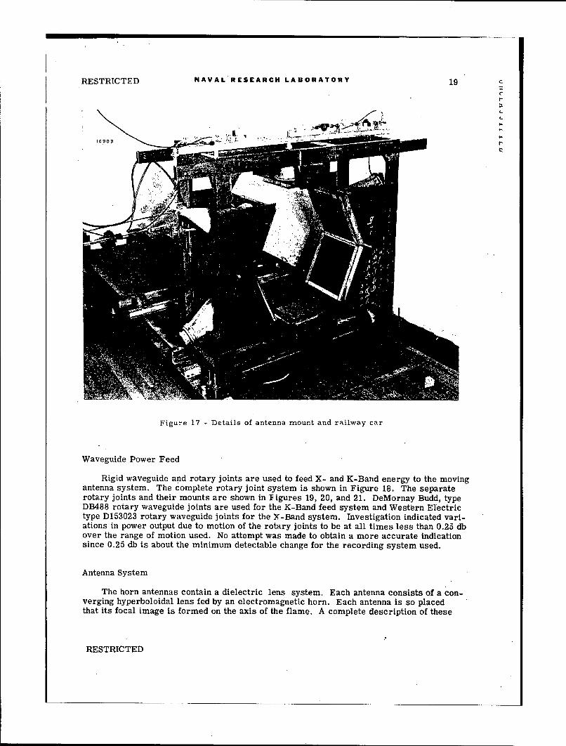
Three and one-half turns of the 1/4-inch steel cable wrapped around the drum providethe necessary friction drive. Driving power is provided to this drum by a 3/4-horsepowermotor (capacitor-start, 1800 rpm, 110 v ac) through a reduction gear (Boston ReductionGear Model ATW38, reduction ratio 124 to 1). Both local and remote control positionswere provided for starting, stopping, and reversing the carriage-drive motor. The motor,reduction gear, friction drive drum, and local control box are shown in Figure 16, A moredetailed view of the car with antenna mounting frame in position is shown in Figure 17.
A flexible line connected to the car drove a cam which actuated a microswitch forevery inch of travel of the car. The switch, in turn, actuated an indicator light mountedon the face edge of the recording cathode-ray tube, thus giving a mark on the record filmfor each inch of travel of the car.
i WIN,"1 ""
Figure 16 - Motor drive system for movable carriage
RESTRICTED
RESTRICTED NAVAL RESEARCH LABORATORY 19 cC
r
rr
Figure 17.- Details of antenna mount and railway car
Waveguide Power Feed
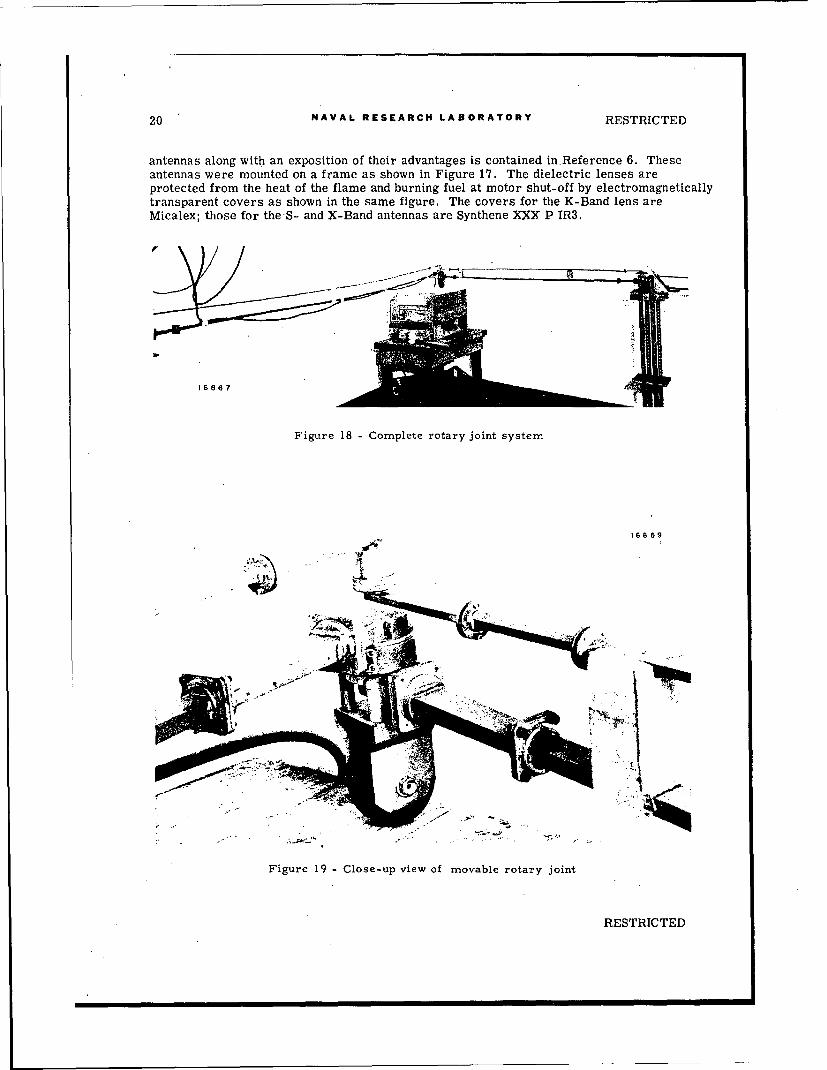
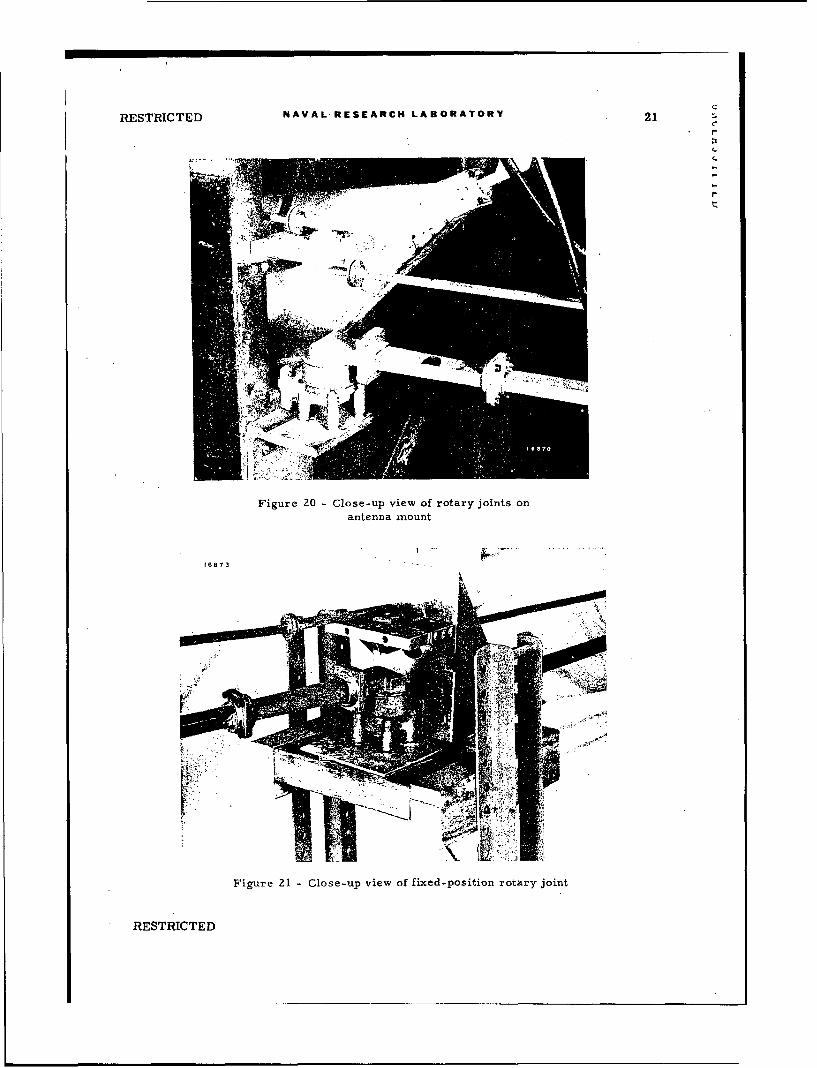
Rigid waveguide and rotary joints are used to feed X- and K-Band energy to the movingantenna system. The complete rotary joint system is shown in Figure 18. The separaterotary joints and their mounts are shown in F igures 19, 20, and 21. DeMornay Budd, typeDB488 rotary waveguide joints are used for the K-Band feed system and Western Electrictype D153023 rotary waveguide joints for the X-Band system. Investigation indicated vari-ations in power output due to motion of the rotary joints to be at all times less than 0.25 dbover the range of motion used. No attempt was made to obtain a more accurate indicationsince 0.25 db is about the minimum detectable change for the recording system used.
Antenna System
The horn antennas contain a dielectric lens system. Each antenna consists of a con-verging hyperboloidal lens fed by an electromagnetic horn. Each antenna is so placedthat its focal image is formed on the axis of the flame. A complete description of these
RESTRICTED
20 NAVAL RESEARCH LABORATORY RESTRICTED
antennas along with an exposition of their advantages is contained inReference 6. Theseantennas were mounted on a frame as shown in Figure .17. The dielectric lenses areprotected from the heat of the flame and burning fuel at motor shut-off by electromagneticallytransparent covers as shown in the same figure. The covers for the K-Band lens areMicalex; those for theS- and X-Band antennas are Synthene XXX P IR3.
16667
Figure 18 Complete rotary joint system
16869
.... ..• .-"'....-5
Figure 19 - Close-up view of movable rotary joint
RESTRICTED
C
RESTRICTED NAVAL RESEARCH LABORATORY 21
4C
C-
Figure 20 - Close-up view of rotary joints onantenna mount
16873
Figure 21 - Close-up view of fixed-position rotary joint
RESTRICTED
22 NAVAL RESEARCH LABORATORY RESTRICTED
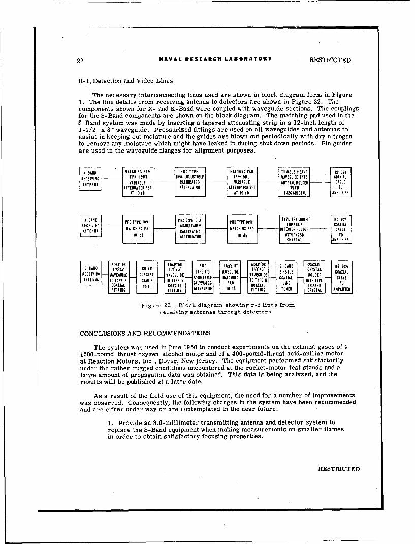
R-F, Detection and Video Lines
The necessary interconnecting lines used are shown in block diagram form in Figure1. The line details from receiving antenna to detectors are shown in Figure 22. Thecomponents shown for X- and K-Band were coupled with waveguide sections. The couplingsfor the S-Band components are shown on the block diagram. The matching pad used in theS-Band system was made by inserting a tapered attenuating strip in a 12-inch length of1-1/2" x 3 "waveguide. Pressurized fittings are used on all waveguides and antennas toassist in keeping out moisture and the guides are blown out periodically with dry nitrogento remove any moisture which might have leaked in during shut down periods. Pin guidesare used in the waveguide flanges for alignment purposes.
R C I I GTP K- 19HU | 153A ADJUSTABLE TPK-19HU WAVE GUIDE TYPECO XIAATNAVARIABLE •- 1 CALIBRATED VARIABLE C RYSTAL HOLDERCATBLE
ATTENUATOR SET| ATTENUATOR ATTENUATOR SET WITH
AT A0 db TAT 0 db IN2TCRYSTAL AMPLIFIER
XBN PRO TYPE 1o9H P RD TYPE 151 A PRD TYPE 109H TCETX•D G[- G "84"REEIIN ADJUSTABLE TUPABLE COAXýIAL
MAT CHING PAD MAIRAE ATCHING PAD -- DETECTOR HOLDER C- ATBLE10 db ATTENUATOR 10 dbl WITH IN238 T
CRYSTAL APIE]
Figure 22 - Block diagram showing r-f lines fromreceiving antennas through detectors
CONCLUSIONS AND RECOMMENDATIONS
The system was used in June 1950 to conduct experiments on the exhaust gases of a1500-pound-thrust oxygen-alcohol motor and of a 400-pound-thrust acid-aniline motorat Reaction Motors, Inc., Dover, New Jersey. The equipment performed satisfactorilyunder the rather rugged conditions encountered at the rocket-motor test stands and alarge amount of propagation data was obtained. This data is being analyzed, and theresults will be published at a later date.
As a result of the field use of this equipment, the need for a number of improvementswas observed. Consequently, the following changes in the system have been recommendedand are either under way or are contemplated in the near future.
1. Provide an 8.6-millimeter transmitting antenna and detector system toreplace the S-Band equipment when making measurements on smaller flamesin order to obtain satisfactory focusing properties.
RESTRICTED
COXA 5F OXAd OXA IN To
RESTRICTED NAVAL RESKARCH LABORATORY 23
2. Provide recording voltmeters to read the average amplitude of the pulsesfor each system. This will eliminate the necessity for transferring most ofthe point-by-point data from the film, the film then being used only to give the rdeviation from the average.
3. Modify the antennas and mounting system to provide greater separationbetween antennas. On the field trip, measurements could not be made out tothe end of the 1500-pound-thrust flame because of the larger hot area near
.the tip of the flame.
4. Improve the gating system or obtain isolation of different frequencies withtransmission-line filters.
5. Provide an automatic calibration system to eliminate the time-consuming,individually hand operated attenuators.
6. Provide a more satisfactory car-position indicator system, since the cable-driven cam system is too cumbersome and not always reliable.
7. Modifycircuitry to cut off low-frequency response (below 10 kc) and other-wise reduce microphonics. As previously used, a flame attenuation of approxi-mately 30 decibels was the maximum that could be measured.
8. Modify the display unit (a) to stabilize the position of the base line on theoscilloscope tube, (b) to increase the intensity of the trace and thus allow higherwriting speeds, (c) to partially blank off the base line to make Its intensitycomparable to the intensity of the displayed pulse and (d) to eliminate interactionbetween the controls for the two parallel-operated display tubes.
9. Provide a pulse-stretching network to equalize the length of each pulse of thethree sets of pulses in order to simplify the photographic problems.
After completion of modifications further experiments are planned on various typesof rocket motors including solid fuel motors.
RESTRICTED
RESTRICTED
REFERENCES
1. Gager, F. M., "Propagation of Electromagnetic Waves through Propellant Gases,"NRL Report R-3197, November 1947
2. Gager, F. M., Zettle, E. N., Bryant, H. M., and Boyd, F. E., NRL Report R-3209,December 1947
3. Gager, F. M., Grimm, H. H., Peck, R. C., and Morehouse, G. D., NRL Report R-3261,March 1948
4. Gager, F. M., and Schleter, G. C., "Electromagnetic Probes for Supersonic Flames,"
NRL Report 3505, June 1949
5. Bryant, H. M., and Fye, D. L., NRL Report 3690, June 1950
6. Boyd, F. E., "Converging Lens Dielectric Antennas," NRL Report 3780, December 1950
7. Wyman, F. E., "Relative Radiation Density and Temperature Distribution of RocketFlames," NRL Report 3823, March 1951
8. "Instruction Book for Oscilloscope TS-239A/UP," Lavoie Laboratories, Morganville,New Jersey, or NAVSHIPS PUBLICATION NO. 91,148, December 15, 1948
24 RESTRICTED

RESTRICTED c
APPENDIXSchematic Diagrams
RESTRICTED
26 NAVAL RESEARCH LABORATORY RESTRITCTED
-00
100
(4-44
-vvvo-lU
RESRITE
27
6A5005 1000 6005
70K .~6 =
.001 410 I,?.00Ijpf1.7 2 6A05 2 6A05
5 . =5
0'OK --- 062 --- 6 .
.. 4700
410K 20 oLf 120 0.IT 01 JAL0f
1000 1000
: :470K -----

RESTRICTEDC
22 K 4.7KOGN CONNECTOR WAY~ 250K 250 30OMh. 2006 290/U GURU
0.25/Lf INEG - ~. GRO 'HR
r4
6--
too I I 11- 1 7
lOOK 3 9K: lOOK T7 0.1
BNC CONNECTOR LLO" IO 5U" 8
UG 280/U1
GATE NO 0.20--
TRIGGER 66 jp
100 GA00
100 lOT2 -1p0 + 4 ~I
Fiur 24 ? ru-us eeaoRESTICTE
RESTRICTED NAVAL RESEARCH LABORATORY 29 c
re-.
RESTRICTED:
30 NAVAL RESEARCH LABORATORY RESTRICTED
Oph ~GOAh UC 230/U
S 1- --.0.,.f INCOUTPUT"Hi OUTP"
U TK : 2 9U 2 2 K O O p 2 2 K S O . h i
B4o . 1 IARY 5 642j(o 5, 2 4o1 5 CIRCUIT IN, .005 1.j o TRIPLICATE
I POLARITY R i o 6 : 0
INPUT 1500 2IA I 3, 34 • •
3.9 4 + 490I MEGII -EC 2 L.
I 209 i490
' 8+
- -:2Of 250V
AMPLIFIER
POWER SUPPLY
Figure 26 - First three-channel pulse arnplifier
RESTRICTED
RESTRICTED NAVAL RESEARCH LABORATORY 31
Cl ZL
w m
04
t~~ - -
LaL
L ,-s]. c;J
RESTRICTED
C
33I-
15K:3500 o 3500
low___ 5K + 1990 1000
180 1ih 5W 2 6AO00 W 0.1 15 6
2 :.001
410K 410KMBA. • 2 +92 5A05
6 - 20Af SOpf 6 E --- 7
lIOOK 2O~f T 470K ::470K210 120 0.1
6AST
2 5i I 4
:220K '386
+ 300V REG
BAUO12.5K 2 6
lOOK1,5
220KOB2
i4.2e
I mixer
RESTRICTED c
NOTE: e-
2 0 K 5 K I -1. THERE ARE THREE +90 2W lOW I
IDENTICAL AMPLI- 1 ---- --- 5' K
E ,E R S . O N E F O R + 2 2 0 o " i
EACH CHANNEL, 180h low iow
WITH MIXER, AND 1800 :lS.pL-COMMON CATHODE 800 609fFOLLOWER 56
2. ALL CAPACITORS I 100 39K 100 39KIN 1f 5,5100
INPUT POSITIVE IFIRST CHANNEL BAKC 2 A IADA.O2
.A. * 01 .1 11 I : 6 -20pf I 6
2,7 7 71KCIN 22 4 lO 0 NEGATIVE lOOK 21 0 201i{ lOOK: 210 2 00i 2p
.A.FROM AMPLIFIER SECOND CHANNEL 0.
MIXED I.FROM AMPLIFIER THIRD CHANNEL ~ ------ .OUTPUT 0.1
MAK.
T22R34
5v
385V 6 log If 16
50i4C a
2385 V 4
ALFILS.
AS FILS.
IS5V to
Figure 28 - Transmitter monitor, amplifier, an
RESTRICTED
35 c
+250V 4500 r
+150V .
0500W"
:39K 100 39K 506
$BA6 5
_1--
4500
+ 250V tow
#2 MIXER
+ 150V tow
9500
4500
+ 2 5 0 V to.- w
#3 MIXER
+ 1500V9500
c
RESTRICTED
5.66K
CATE. 2 90 0.l 51 51Ii, -' -- 8200
5KFO 5Oph O.)A 12C51 GAEONA SNAK 10
SINA 0. 017 3 0.1 f --- 6 0.1 2 ~ 2...
I.THR AR E C THREE.
SC E AT C KWITHO 17 20 + 2000 l f-AO COMMN LOAD47 10 O~f-21 o I
N IVE: INPU FROMfSIGNAIFROM A.0.1ULTHEES ORETHERWIEE TAS.TR ~ 25 O. 686 P A
SCHEMATIC. MONITO + 2010V66 5
GIE Njp INLF OM I 3. 1 I ,I- 107 2h5CUNES OTERIS NRNMITREO.C B 0. I~f -
00201 6 2 I0 2500
00-2001 I9500
1ZAS FILSK
NEC rVAiXIL20
RESTRNNICTO TEDK Fiur 29O -0 Mxraplfiru

37 C
r
-- 7-
PULSE SHAPERTO POWER SUPPLY 4,1K
5ALb15K: 470v, 82K 2.514h
IX STAGE 100 oo f - . 6b Ali I T E 0NCELEOTOR SWITCHs _U_ 0.1 00200/0|I
4I
6f0inJ6 2 5- 6 0.1 CONNECTOR
686l 2 1 06MUTPUT
27KoE IN 47AI O.I 7l 7 1' ý
39 33 T a 401 I.86 4.16
APACýITO R ARE1STA 6 ES
NOTE: ALL CAPACITORS ARE GIVEN IN ufUNLESS OTHERWISE SPECIFIED.

UNCLASSIFIED
rC.,
INPUT PULSE SHAPING BINARY DIVIDER -OUTPU
ONE OF SIX STAGES
B+!TO POWER SUPPLY POWER SUPPLY
I1 K
"2 IOOK1 f 2.
L5K O 515 K I: : : 340 ( ;480K 82K ::15K GALS 2. (2 IN3
,1.--K6-1.TO5K
0. IDppF 50 NEXT TO.1 2 IOO.wA IO0$f SAC RE
BNC CONNECTOR 5 A0000AUUG 2901U 0.1 2 6 0. 1434= 1OY5 JR 2)T I I4P7K 50I_._
I 500 2 1K 1 0.1 OTPUT21 50K 58KK
Il1K .,I4pg I4
.TOE CATHODE RESISTORS ANDC
I NI PU T fI 1 j1 00OM 0ON T0 ALL BINARY DIVIDE
GRI
THORDARSONT22 000
TO BINARY DIVIDERS
5U4 THORDARSON
1100 T- 10054 2K OUTPUT PULSE SOAPER,S0 8C + - 25 + AND CATHODE FOLLOWERS
10 30 30 1D
HEATERS OF DIVIDERS _L
THRO ARSONT-21FID
HEATERS OF PULSE SHAPERSAND CATHODE FOLLOWERS
Figure 30 - Pulse-divider unit
UNCLASSIFIED

39
VERT 1OT - P
20-3004
tIME ~ ~ ~ 4 50K 50K 20
V RT FUNCLASSIFIEDS

UNCLASSIFIEDC,
: ISMD :3K 5-N0,,
0 0 -0 3 0 /UT I 4 3 0 .6 .00 . O i. f .I ~ :: O d 2 6 - o h
0065 1.5P. 000ESW E
22 :2T 00 1.5 80 0 6
VIE -SC'.O,. 2(OK
B i c .S.N5 #f1
056
290 u to 4-3 ol 405
30I 4-0 00 lo 0 100 - - 8 21 2 p
ION'00
+0ll ::C F61 AIN lI0 GiAT
iL 000f OTIS
42~~~~ 2O/~ 50? 601.
CONNICON ~ -3304
IN1U 003 100 2O0
OUTPUT, 27X gSYT ]E
?Fiur 31 0- Disla unit BA
UNCLASSIFIEDIN1 6X5 lo
0 01 T0 2T0

ATI 135 663 (COPIES OBTAINABLE FROM ASTIA'DSC)
OFFICE OF NAVAL RESEARCH, NAVAL RESEARCH LABS. WASH., D.C.(NRL REPORT 3886)
MICROWAVE INSTRUMENTATION FOR MULTIFREQUENCY ATTENUATIONMEASUREMENTS THROUGH PROPELLANT GASES - AND APPENDIX
BALWANZ, WoW.; MOREHOUSE, GoD.; HEADRICK, JoM. 13 FES05239PP PHOTOS, DIAGRS, GRAPH
WAVES, ELECTROMAGNETIC - PHYSICS (62)ATTENUATION RADIATION (5)
FLAMES, EXHAUSTENGINES, ROCKET - EXHAUST /MICROWAVES /
EO 105oi ci1 5c ov,,