Embed Size (px)
Citation preview
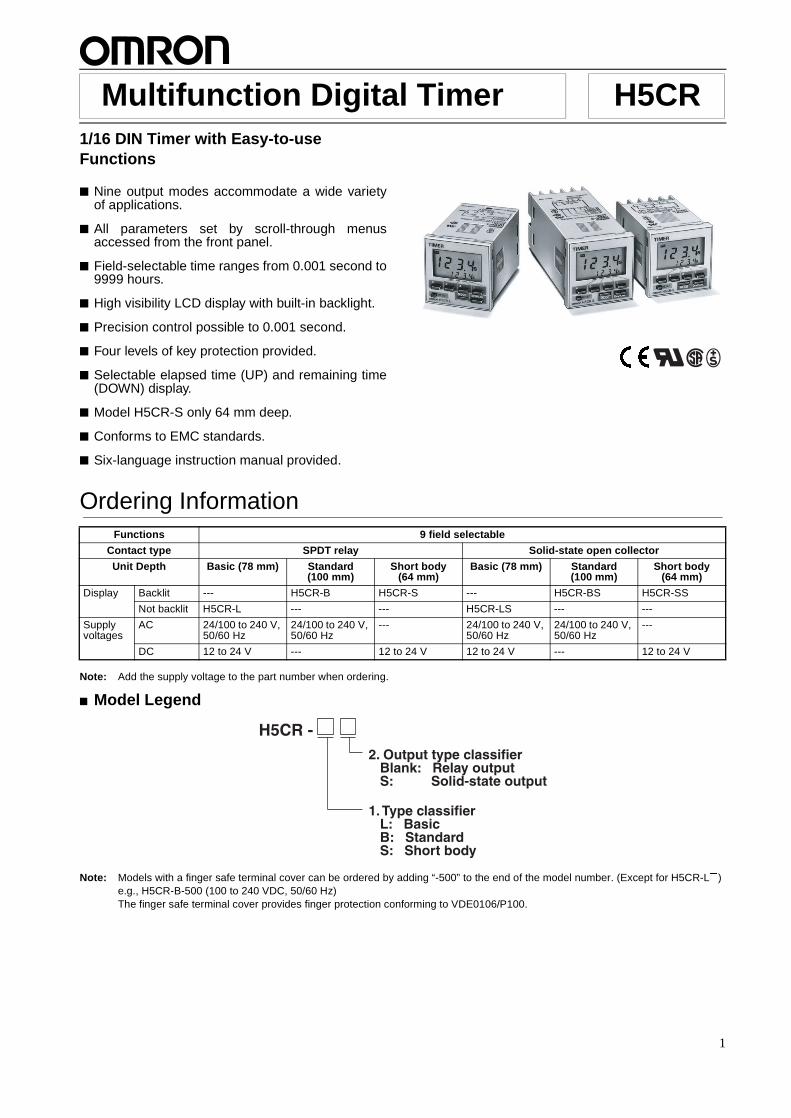
H5CR Multifunction Digital Timer
1/16 DIN Timer with Easy-to-use Functions� Nine output modes accommodate a wide varietyof applications.
� All parameters set by scroll-through menusaccessed from the front panel.
� Field-selectable time ranges from 0.001 second to9999 hours.
� High visibility LCD display with built-in backlight.
� Precision control possible to 0.001 second.
� Four levels of key protection provided.
� Selectable elapsed time (UP) and remaining time(DOWN) display.
� Model H5CR-S only 64 mm deep.
� Conforms to EMC standards.
� Six-language instruction manual provided.
Ordering Information
Note: Add the supply voltage to the part number when ordering.
� Model Legend
Note: Models with a finger safe terminal cover can be ordered by adding “-500” to the end of the model number. (Except for H5CR-L#)e.g., H5CR-B-500 (100 to 240 VDC, 50/60 Hz)The finger safe terminal cover provides finger protection conforming to VDE0106/P100.
RC+
Functions 9 field selectable
Contact type SPDT relay Solid-state open collector
Unit Depth Basic (78 mm) Standard (100 mm)
Short body (64 mm)
Basic (78 mm) Standard (100 mm)
Short body (64 mm)
Display Backlit --- H5CR-B H5CR-S --- H5CR-BS H5CR-SS
Not backlit H5CR-L --- --- H5CR-LS --- ---
Supply voltages
AC 24/100 to 240 V, 50/60 Hz
24/100 to 240 V, 50/60 Hz
--- 24/100 to 240 V, 50/60 Hz
24/100 to 240 V, 50/60 Hz
---
DC 12 to 24 V --- 12 to 24 V 12 to 24 V --- 12 to 24 V
H5CR - 2. Output type classifier Blank: Relay output S: Solid-state output
1. Type classifier L: Basic B: Standard S: Short body
1
H5CRH5CR
� Accessories (Order Separately)
Note: 1. Y92A-48G is a finger safe terminal cover which is attached to the P3G-08 Socket.
2. Supplied with each Unit.
Specifications
Name Model
Hard cover Y92A-48
Soft cover Y92A-48F1
Track Mounting/Front Connecting Socket (for H5CR-L# only)
--- P2CF-08
Finger safe type P2CF-08-E
Back Connecting Socket (for H5CR-L# only) --- P3G-08
Finger safe type P3G-08 with Y92A-48G (see note 1)
Finger Safe Terminal Cover for H5CR-B#/-S# Y92A-48T
Flush Mounting Adapter (see note 2) Y92F-30
Model H5CR-L (Basic type) H5CR-B (Standard type) H5CR-S (Short body type)
Classification Digital timer
Mounting Flush or Surface mounting Flush mounting
External connections 8P socket Screw terminals (M3.5 screw)
Enclosure ratings IP40 IP54 (panel surface)
Display modes Elapsed time (UP), remaining time (DOWN)
Output modes A, A-1, A-2, A-3, b, b-1, d, E, F
Reset system Power reset (except A-3, b-1, and F modes), External, manual, automatic resets (internal according to A-1, b, b-1, d, and E mode operation)
Input signals Start, reset inputs Start, reset, gate, key protect inputs
Input method No-voltage input: Via opening and closing of contact
Control outputs SPDT contact output and transistor output (NPN open collector)
Display LCD without backlight LCD with backlight
Digits 4 digits
Max. time settings 9.999 s (0.001 s units), 99.99 s (0.01 s units), 999.9 s (0.1 s unit), 9999 s (1 s unit), 99 min 59 s (1 s unit), 999.9 min (0.1 min unit), 9999 min (1 min unit), 99 hr 59 min (1 min unit), 999.9 hr (0.1 hr unit), 9999 hr (1 hr unit)
Memory backup Backup time for power interruption: Approx. 10 years at 20�C
Mounting method DIN track mounting, surface mounting, and flush mounting
Flush mounting
Approved standards UL508, CSA C22.2 No. 14Conforms to EN61010-1
2
H5CRH5CR
� Ratings
� Characteristics
Model H5CR-L (Basic type) H5CR-B (Standard type) H5CR-S (Short body type)
Rated supply voltage 100 to 240 VAC (50/60 Hz)24 VAC (50/60 Hz)12 to 24 VDC (permissible ripple: 20% max.)
100 to 240 VAC (50/60 Hz)24 VAC (50/60 Hz)
12 to 24 VDC (permissible ripple: 20% max.)
Operating voltage range 85% to 110% of rated voltage
Power consumption Approx. 3 VA at 50 Hz, 240 VAC; approx. 1 W at 24 VDC
Approx. 5 VA at 50 Hz, 240 VAC Approx. 2 W at 24 VDC
Reset and control signals Min. pulse width 1 ms/20ms selectable
Gate --- Min. pulse width: Approx. 20 ms
Key protect --- Response time: 1 s
One-shot time 0.1 to 20 s (select from 7 kinds) or sustained
Power reset (except A-3, b-1, and F mode)
Min. power opening time: 0.5 s
Signal, reset, gate inputs No-voltage inputON impedance: 1 kW max. (Approx. 2 mA when 0 W)ON residual voltage: 2 V max.OFF impedance: 100 kW min.
Key protect input --- No-voltage input ON impedance: 1 kW max. (Approx. 2 mA when 0 W)ON residual voltage:1 V max.OFF impedance: 100 kW min.
Control outputs Contacts: 5 A at 250 VAC, resistance load (cos f = 1)Transistor output: Open collector 100mA at 30 VDC max. residual voltage 2 V max. (Approx. 1 V)
Ambient temperature –10�C to 55�C (with no icing)
Storage temperature –25�C to 65�C (with no icing)
Ambient humidity 35% to 85%
Case Light gray
Repeat accuracy (including temperature and voltage effects)
Power start: �0.01% �0.05 s max.Control signal start: �0.005% �0.03 s max. *(rate for set value)
Insulation resistance 100 MW min. (at 500 VDC) (between current-carrying terminal and exposed non-current-carrying metal parts, and between non-continuous contacts)
Dielectric strength 2,000 VAC, 50/60 Hz for 1 min (between current-carrying terminal and exposed non-current-carrying metal parts) for 100 to 240 VAC type1,000 VAC for 24VAC/12 to 24 VDC transistor output type
Surge voltage 3 kV (between power terminals) for 100 to 240 VAC type, 1 kV for 24 VAC/12 to 24 VDC type4.5 kV (between current-carrying terminal and exposed non-current-carrying metal parts) for 100 to 240 VAC type, 1.5 kV for 24 VAC/12 to 24 VDC type
Noise immunity �2 kV (between power terminals)(�480 V for 12 to 24 VDC) and �600 V (between input terminals), square-wave noise by noise simulator (pulse width: 100 ns/1 ms, 1-ns rise)
Static immunity Malfunction: 8 kV; destruction: 15 kV
Vibration Destruction 10 to 55 Hz with 0.75-mm single amplitude each in three directions
Malfunction 10 to 55 Hz with 0.5-mm single amplitude each in three directions
Shock Destruction 294 m/s2 (30G) each in three directions
Malfunction 98 m/s2 (10G) each in three directions
Life expectancy Mechanical 10 million operations min.
Electrical 100,000 operations min. (5 A at 250 VAC in load resistance)
EMC (EMI): EN50081-2Emission Enclosure: EN55011 Group 1 class AEmission AC Mains: EN55011 Group 1 class A(EMS): EN50082-2Immunity ESD: EN61000-4-2: 4 kV contact discharge (level 2)
8 kV air discharge (level 3)Immunity RF-interference: ENV50140: 10 V/m (80 MHz to 1 GHz) (level 3)Immunity Conducted Disturbance: ENV50141: 10 V (0.15 to 80 MHz) (level 3)Immunity Burst: EN61000-4-4: 2 kV power-line (level 3)
2 kV I/O signal-line (level 4)
Weight H5CR-L: Approx. 105 g, H5CR-B: Approx. 160 g, H5CR-S: Approx. 120 g
3
H5CRH5CR
Nomenclature
� Factory SettingsThe following table shows the timer settings when it is shipped. Please change the settings as necessary to suit the system before opera-tion. Settings and the display receive power from the internal battery and are therefore unaffected by external power interruptions.
Note: With the initial settings, there will be no output even if the power supply is connected. External inputs and outputs cannot be usedwithout a power supply.
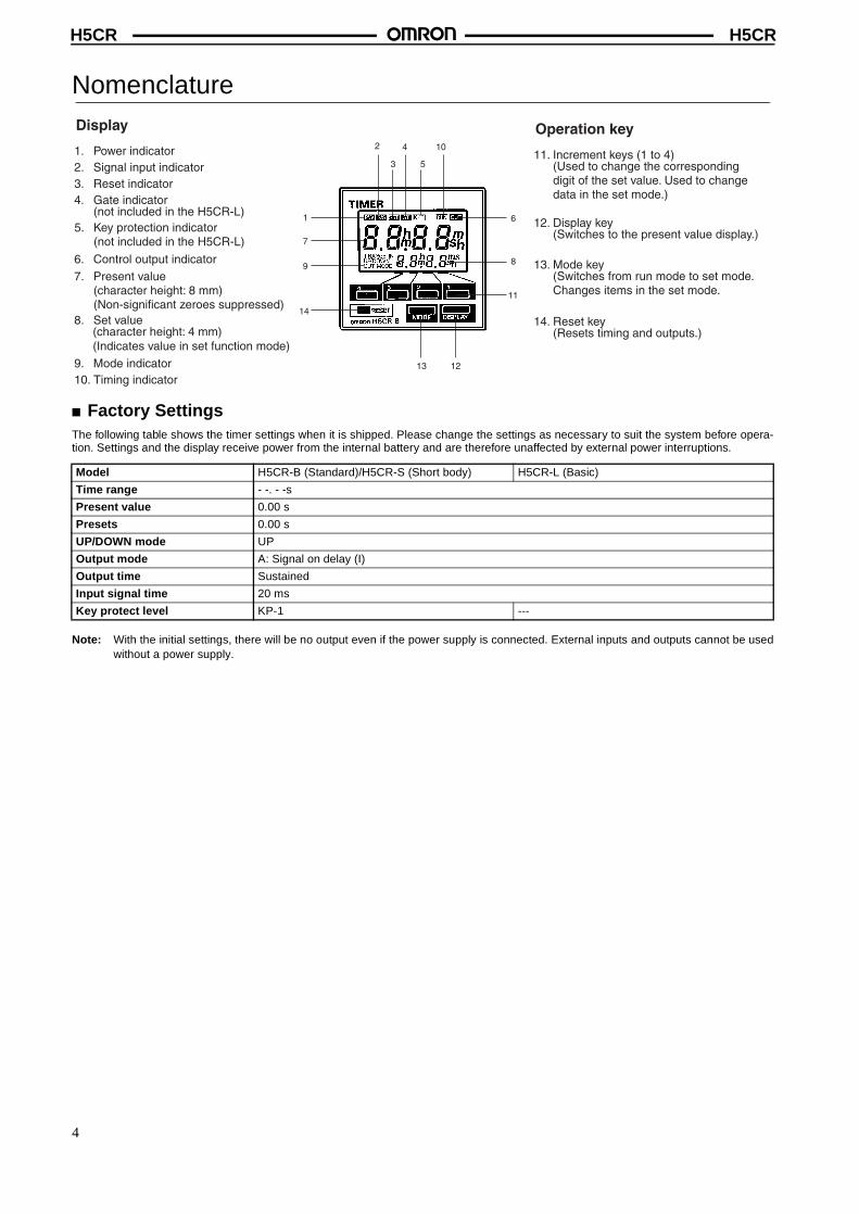
1. Power indicator2. Signal input indicator3. Reset indicator4. Gate indicator
(not included in the H5CR-L)5. Key protection indicator
(not included in the H5CR-L)
6. Control output indicator7. Present value
(character height: 8 mm)(Non-significant zeroes suppressed)
8. Set value (character height: 4 mm) (Indicates value in set function mode)
9. Mode indicator10. Timing indicator
Display
11. Increment keys (1 to 4)(Used to change the corresponding digit of the set value. Used to change data in the set mode.)
12. Display key(Switches to the present value display.)
Operation key
13. Mode key(Switches from run mode to set mode. Changes items in the set mode.
14. Reset key(Resets timing and outputs.)
2
3
4
5
10
1213
14
9
1
7
11
6
8
Model H5CR-B (Standard)/H5CR-S (Short body) H5CR-L (Basic)
Time range - -. - -s
Present value 0.00 s
Presets 0.00 s
UP/DOWN mode UP
Output mode A: Signal on delay (I)
Output time Sustained
Input signal time 20 ms
Key protect level KP-1 ---
4
H5CRH5CR
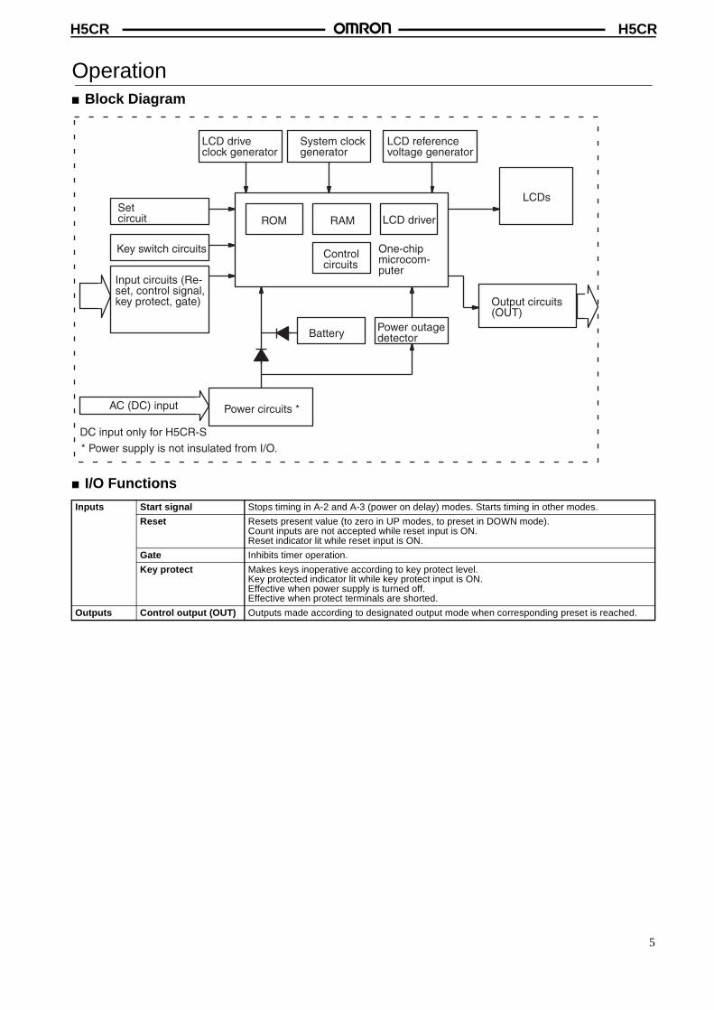
Operation� Block Diagram
� I/O Functions
Inputs Start signal Stops timing in A-2 and A-3 (power on delay) modes. Starts timing in other modes.
Reset Resets present value (to zero in UP modes, to preset in DOWN mode).Count inputs are not accepted while reset input is ON.Reset indicator lit while reset input is ON.
Gate Inhibits timer operation.
Key protect Makes keys inoperative according to key protect level.Key protected indicator lit while key protect input is ON.Effective when power supply is turned off.Effective when protect terminals are shorted.
Outputs Control output (OUT) Outputs made according to designated output mode when corresponding preset is reached.
Key switch circuits
Input circuits (Re-set, control signal, key protect, gate)
AC (DC) input
LCD drive clock generator
RAM
Power circuits *
System clock generator
ROM
Control circuits
Battery
LCD reference voltage generator
LCD driver
One-chip microcom-puter
Power outagedetector
Output circuits (OUT)
Setcircuit
LCDs
* Power supply is not insulated from I/O.
DC input only for H5CR-S
5
H5CRH5CR
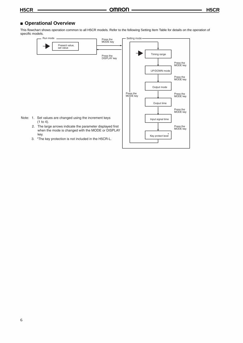
� Operational OverviewThis flowchart shows operation common to all H5CR models. Refer to the following Setting Item Table for details on the operation of specific models.
Run mode
Present value,set value
Timing range
Key protect level
Input signal time
Output time
Output mode
UP/DOWN mode
Setting mode
Press theDISPLAY key
Press theMODE key
Press theMODE key
Press theMODE key
Press theMODE key
Press theMODE key
Press theMODE key
Press theMODE key
Note: 1. Set values are changed using the increment keys (1 to 4).
2. The large arrows indicate the parameter displayed first when the mode is changed with the MODE or DISPLAY key.
3. *The key protection is not included in the H5CR-L.*
6
H5CRH5CR
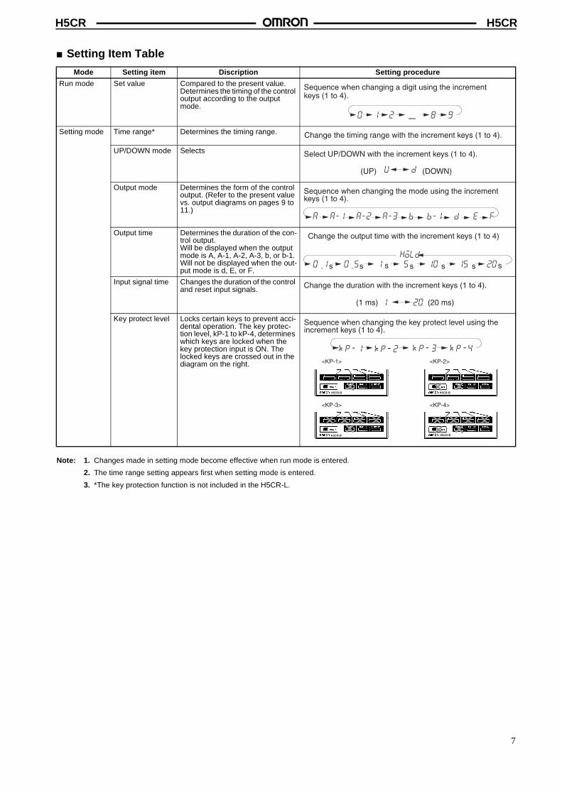
� Setting Item Table
Note: 1. Changes made in setting mode become effective when run mode is entered.
2. The time range setting appears first when setting mode is entered.
3. *The key protection function is not included in the H5CR-L.
Mode Setting item Discription Setting procedure
Run mode Set value Compared to the present value. Determines the timing of the control output according to the output mode.
Setting mode Time range* Determines the timing range.
UP/DOWN mode Selects
Output mode Determines the form of the control output. (Refer to the present value vs. output diagrams on pages 9 to 11.)
Output time Determines the duration of the con-trol output.Will be displayed when the output mode is A, A-1, A-2, A-3, b, or b-1. Will not be displayed when the out-put mode is d, E, or F.
Input signal time Changes the duration of the control and reset input signals.
Key protect level Locks certain keys to prevent acci-dental operation. The key protec-tion level, kP-1 to kP-4, determines which keys are locked when the key protection input is ON. The locked keys are crossed out in the diagram on the right.
0 1 2 8 9
Sequence when changing a digit using the incrementkeys (1 to 4).
Change the timing range with the increment keys (1 to 4).
u d(UP) (DOWN)
Select UP/DOWN with the increment keys (1 to 4).
Sequence when changing the mode using the increment keys (1 to 4).
a a-1 a-2 a-3 b b-1 d e f
Change the output time with the increment keys (1 to 4)
0 1. s 1 s0 5. s 5s 10 s 15 s 20 shold
Change the duration with the increment keys (1 to 4).
1 20(1 ms) (20 ms)
Sequence when changing the key protect level using theincrement keys (1 to 4).
3 4p p
<KP-1> <KP-2>
<KP-4><KP-3>
1p 2p
H5CR-B
H5CR-B
H5CR-B
H5CR-B
7
H5CRH5CR
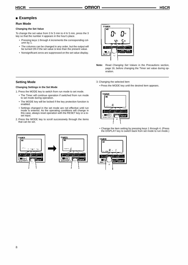
� ExamplesRun Mode
Changing the Set Value
To change the set value from 3 hr 5 min to 4 hr 5 min, press the 3key so that the number 4 appears in the hour’s place.
• Pressing keys 1 through 4 increments the corresponding col-umn by 1.
• The columns can be changed in any order, but the output willbe turned ON if the set value is less than the present value.
• Nonsignificant zeros are suppressed on the set value display.
Note: Read Changing Set Values in the Precautions section,page 16, before changing the Timer set value during op-eration.
Setting Mode
Changing Settings in the Set Mode
1. Press the MODE key to switch from run mode to set mode.
• The Timer will continue operation if switched from run modeto set mode during operation.
• The MODE key will be locked if the key protection function isenabled.
• Settings changed in the set mode are not effective until runmode is entered. As the operating conditions will change inthis case, always reset operation with the RESET key or a re-set input.
2. Press the MODE key to scroll successively through the itemsthat can be set.
3. Changing the selected item
• Press the MODE key until the desired item appears.
• Change the item setting by pressing keys 1 through 4. (Pressthe DISPLAY key to switch back from set mode to run mode.)
8
H5CRH5CR
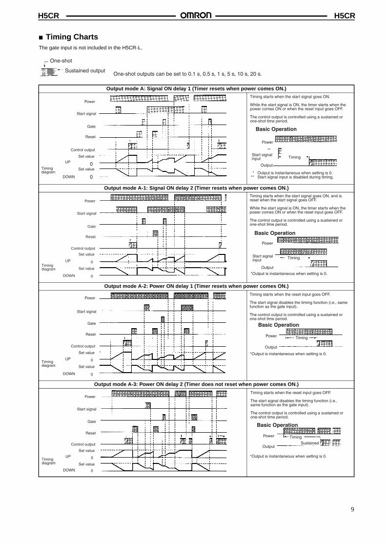
� Timing ChartsThe gate input is not included in the H5CR-L.
One-shot outputs can be set to 0.1 s, 0.5 s, 1 s, 5 s, 10 s, 20 s.
One-shot
Sustained output
Output mode A: Signal ON delay 1 (Timer resets when power comes ON.)
Output mode A-1: Signal ON delay 2 (Timer resets when power comes ON.)
Output mode A-2: Power ON delay 1 (Timer resets when power comes ON.)
Output mode A-3: Power ON delay 2 (Timer does not reset when power comes ON.)
Power
Start signal
Gate
Reset
Control output
Set value
Timingdiagram
UP
DOWN
0
0
Set value
Timing starts when the start signal goes ON.
While the start signal is ON, the timer starts when the power comes ON or when the reset input goes OFF.
The control output is controlled using a sustained or one-shot time period.
Basic Operation
Power
**Start signal input Timing
Output
* Output is instantaneous when setting is 0.** Start signal input is disabled during timing.
Power
Start signal
Gate
Reset
Control output
Set value
Timingdiagram
UP
DOWN
0
0
Set value
Timing starts when the start signal goes ON, and is reset when the start signal goes OFF.
While the start signal is ON, the timer starts when the power comes ON or when the reset input goes OFF.
The control output is controlled using a sustained or one-shot time period.
*Output is instantaneous when setting is 0.
Basic Operation
Power
Start signal input Timing
Output
Power
Start signal
Gate
Reset
Control output
Set value
Timingdiagram
UP
DOWN
0
0
Set value
Timing starts when the reset input goes OFF.
The start signal disables the timing function (i.e., same function as the gate input).
The control output is controlled using a sustained or one-shot time period.
*Output is instantaneous when setting is 0.
Basic Operation
Power Timing
OutputSustained
9
H5CRH5CR
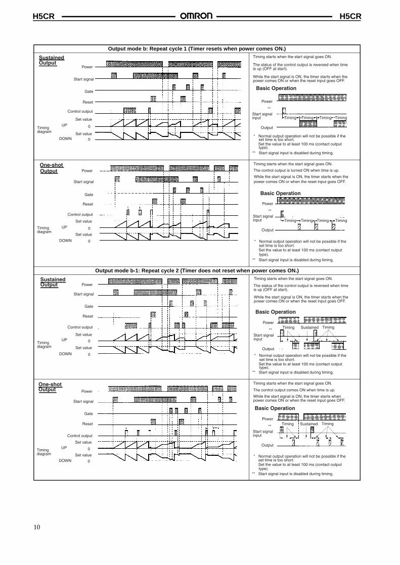
Output mode b: Repeat cycle 1 (Timer resets when power comes ON.)
Output mode b-1: Repeat cycle 2 (Timer does not reset when power comes ON.)
Power
Start signal
Gate
Reset
Control output
Set value
Timingdiagram
UP
DOWN
0
0Set value
Sustained Output
Timing starts when the start signal goes ON.
The status of the control output is reversed when time is up (OFF at start).
While the start signal is ON, the timer starts when the power comes ON or when the reset input goes OFF.
* Normal output operation will not be possible if the set time is too short.Set the value to at least 100 ms (contact output type).
** Start signal input is disabled during timing.
Basic Operation
Power
**Start signal input Timing
Output
TimingTimingTiming
Power
Start signal
Gate
Reset
Control output
Set value
Timingdiagram
UP
DOWN
0
0
Set value
One-shot Output
Timing starts when the start signal goes ON.
The control output is turned ON when time is up.
While the start signal is ON, the timer starts when the power comes ON or when the reset input goes OFF.
* Normal output operation will not be possible if the set time is too short.Set the value to at least 100 ms (contact output type).
** Start signal input is disabled during timing.
Basic Operation
Power
**Start signal input
Output
TimingTimingTimingTiming
Power
Start signal
Gate
Reset
Control output
Set value
Timingdiagram
UP
DOWN
0
0
Set value
Sustained Output
Timing starts when the start signal goes ON.
The status of the control output is reversed when time is up (OFF at start).
While the start signal is ON, the timer starts when the power comes ON or when the reset input goes OFF.
* Normal output operation will not be possible if the set time is too short.Set the value to at least 100 ms (contact output type).
** Start signal input is disabled during timing.
Sustained
Basic Operation
Power
**Start signal input
Output
Timing Timing
Power
Start signal
Gate
Reset
Control output
Set value
Timingdiagram
UP
DOWN
0
0
Set value
One-shot Output
Timing starts when the start signal goes ON.
The control output comes ON when time is up.
While the start signal is ON, the timer starts when power comes ON or when the reset input goes OFF.
Sustained
Basic Operation
Power
**Start signal input
Output
Timing Timing
* Normal output operation will not be possible if the set time is too short.Set the value to at least 100 ms (contact output type).
** Start signal input is disabled during timing.
SustainedTiming Timing
10
H5CRH5CR
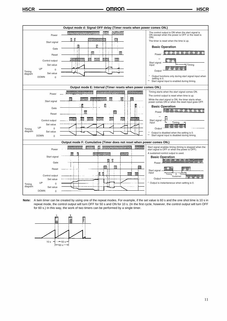
Note: A twin timer can be created by using one of the repeat modes. For example, if the set value is 60 s and the one shot time is 10 s inrepeat mode, the control output will turn OFF for 50 s and ON for 10 s. (In the first cycle, however, the control output will turn OFFfor 60 s.) In this way, the work of two timers can be performed by a single timer.
Output mode d: Signal OFF delay (Timer resets when power comes ON.)
Output mode E: Interval (Timer resets when power comes ON.)
Output mode F: Cumulative (Timer does not reset when power comes ON.)
Power
Start signal
Gate
Reset
Control output
Set value
Timingdiagram
UP
DOWN
0
0
Set value
The control output is ON when the start signal is ON (except when the power is OFF or the reset is ON).
The timer is reset when the time is up.
* Output functions only during start signal input when setting is 0.
** Start signal input is enabled during timing.
Basic Operation
Power
**Start signal input
Output
Timing
Power
Start signal
Gate
Reset
Control output
Set value
Timingdiagram
UP
DOWN
0
0
Set value
Timing starts when the start signal comes ON.
The control output is reset when time is up.
While the start signal is ON, the timer starts when power comes ON or when the reset input goes OFF.
* Output is disabled when the setting is 0.** Start signal input is disabled during timing.
Basic Operation
Power
**Start signal input
Output
Timing
Power
Start signal
Gate
Reset
Control output
Set value
Timingdiagram
UP
DOWN
0
0
Set value
Start signal enables timing (timing is stopped when the start signal is OFF or when the power is OFF).
A sustained control output is used.
* Output is instantaneous when setting is 0.
Sustained
Basic Operation
Power
Start signal input
Output
Timing Timing
10 s 50 s60 s
11
H5CRH5CR
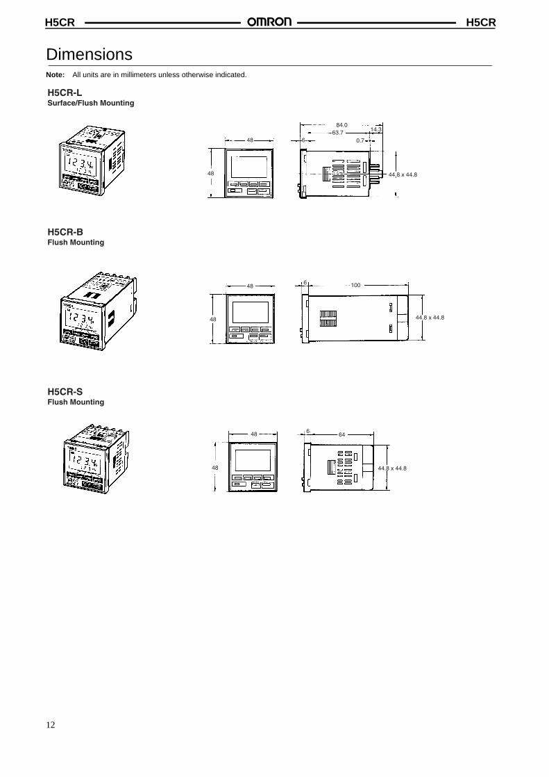
DimensionsNote: All units are in millimeters unless otherwise indicated.
48
48
84.063.7
6 0.7
14.3
44.8 x 44.8
48
48
664
44.8 x 44.8
H5CR-LSurface/Flush Mounting
H5CR-BFlush Mounting
H5CR-SFlush Mounting
48
48
1006
44.8 x 44.8
12
H5CRH5CR
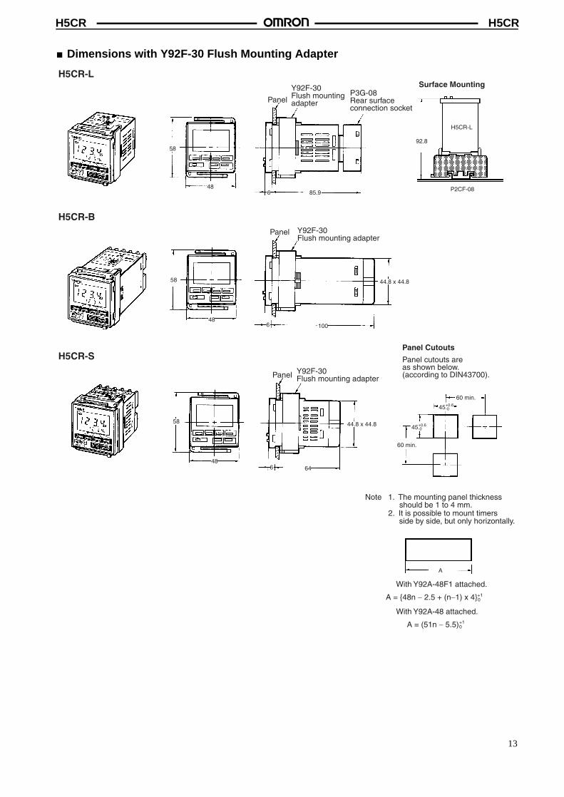
� Dimensions with Y92F-30 Flush Mounting Adapter
48
58
6 85.9
58
486 100
92.8
A
H5CR-L
H5CR-B
H5CR-SPanel Cutouts
Panel cutouts areas shown below.(according to DIN43700).
Surface Mounting
Y92F-30Flush mounting adapter
Panel
Y92F-30Flush mounting adapterPanel
Note 1. The mounting panel thickness should be 1 to 4 mm.
2. It is possible to mount timers side by side, but only horizontally.
H5CR-L
P2CF-08
58
486 64
60 min.
60 min.
45+0.6-0
45+0.6-0
+10A = {48n - 2.5 + (n-1) x 4}
Panel
Y92F-30Flush mounting adapter
P3G-08Rear surfaceconnection socket
44.8 x 44.8
With Y92A-48F1 attached.
44.8 x 44.8
+10A = (51n - 5.5)
With Y92A-48 attached.
13
H5CRH5CR
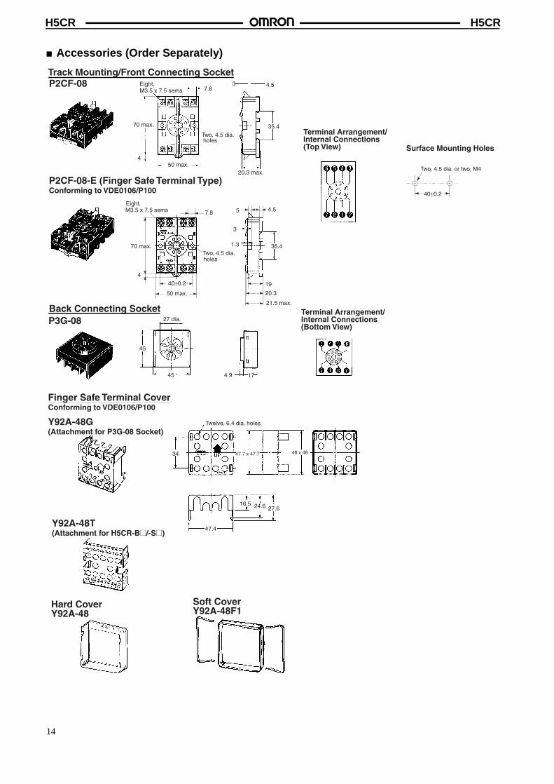
� Accessories (Order Separately)
Eight, M3.5 x 7.5 sems
Two, 4.5 dia. holes
70 max.
50 max.20.3 max.
7.83 4.5
35.4
4
Track Mounting/Front Connecting SocketP2CF-08
P2CF-08-E (Finger Safe Terminal Type)Conforming to VDE0106/P100
Terminal Arrangement/Internal Connections (Top View) Surface Mounting Holes
40±0.2
Two, 4.5 dia. or two, M4
50 max.
40±0.2
70 max.
Eight, M3.5 x 7.5 sems
Two, 4.5 dia. holes
7.8
4
35.4
21.5 max.
20.3
19
3
1.3
5 4.5
45
27 dia.
45 4.9 17
Back Connecting SocketP3G-08
Terminal Arrangement/Internal Connections (Bottom View)
Finger Safe Terminal CoverConforming to VDE0106/P100
Y92A-48G(Attachment for P3G-08 Socket)
Y92A-48T(Attachment for H5CR-B@/-S@)
Hard CoverY92A-48
Soft CoverY92A-48F1
Twelve, 6.4 dia. holes
34 47.7 x 47.7 48 x 48
47.4
16.5 24.6 27.6
14
H5CRH5CR
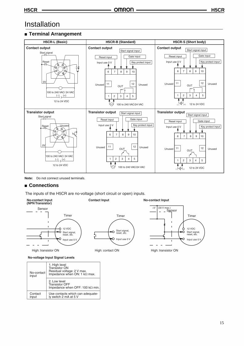
Installation � Terminal Arrangement
Note: Do not connect unused terminals.
� Connections
H5CR-L (Basic) H5CR-B (Standard) H5CR-S (Short body)
Contact output
100 to 240 VAC/ 24 VAC(-) (+)
12 to 24 VDC
12
34 5
6
78
0V
Start signal
Reset
11 12
6 7 8 9 10
1 2 3 4 5
Input use 0 V
Reset input
Start signal input
Gate input
Key protect input
OUT
100 to 240 VAC/24 VAC
Contact output
Unused Unused
Contact output
12 to 24 VDC(-) (+)
11 12
6 7 8 9 10
1 2 3 4 5
Input use 0 V
Reset input Gate input
Key protect input
OUTUnused Unused
Start signal input
Transistor output
12
34 5
6
78
Start signal
Reset
0V
100 to 240 VAC/ 24 VAC(-) (+)
12 to 24 VDC
Unused
Transistor output
11 12
6 7 8 9 10
1 2 3 4 5
Input use 0 V
Reset input Gate input
Key protect input
OUT
100 to 240 VAC/24 VAC
Unused Unused
Start signal input Transistor output
12 to 24 VDC(-) (+)
11 12
6 7 8 9 10
1 2 3 4 5
Input use 0 V
Reset input Gate input
Key protect input
OUTUnused Unused
Start signal input
The inputs of the H5CR are no-voltage (short circuit or open) inputs.
No-voltage Input Signal Levels
No-contact input
Contactinput
1. High levelTransistor ONResidual voltage: 2 V max.Impedance when ON: 1 kW max.
2. Low levelTransistor OFFImpedance when OFF: 100 kW min.
Use contacts which can adequate-ly switch 2 mA at 5 V
No-contact Input(NPN Transistor)
Contact Input No-contact Input
Sensor
Timer
High: transistor ON
Timer
High: contact ON High: transistor ON
Sensor
Timer
12 VDC
+V (30 V max.)
Input use 0 V
Start signal, reset, etc.
12 VDC
Start signal, reset, etc.
Input use 0 V
Start signal, reset, etc.
Input use 0 V
15
H5CRH5CR
Precautions� Power Supplies• The input circuit is not insulated from the power supply circuit.
The internal circuit might be damaged by a surrounding AC cir-cuit, so use an insulated AC power supply with equipment con-nected to the input circuit.
• If power is interrupted for less than 10 ms, operation will continuenormally. If power is interrupted for between 10 and 500 ms, op-eration will be inconsistent, and timing may stop or reset, de-pending on the mode.
• Connect the power supply voltage through a relay or switch insuch a way that the voltage reaches a fixed value immediately.
• Depending on switching frequency, current surges may degraderelay contacts; relays with a capacity greater than 10 A are rec-ommended.
� Input and Output• Do not use external sources to increase the voltage of input sig-
nals (control signal, reset, gate, and key protection).
• Be sure that the load of the control output (contact, transistor) isless than the maximum values indicated in the specifications. Ifthe output load exceeds the recommended value, the life span ofthe contact output type will be shortened dramatically, and thetransistor of the transistor output type will be damaged.
• The transistor output is insulated from the internal circuitry by aphotocoupler, so either NPN or PNP transistors can be used.
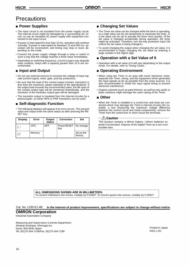
� Self-diagnostic Function• The following displays will appear if an error occurs. The present
value and output enter the same status as after pressing the RE-SET key.
� Changing Set Values• The Timer set value can be changed while the timer is operating,
so a high value can be set temporarily to inactivate the timer, ora low value can be set to activate the timer more quickly. (If theset value is changed accidentally during operation, the timermight be activated. Therefore, turn the key protection input ONunless the set value is being changed.)
• To avoid changing the output when changing the set value, it isrecommended to begin changing the set value by entering alarge number in the higher digit.
� Operation with a Set Value of 0• Operation with a set value of 0 will vary depending on the output
mode. For details, refer to Timing Charts.
� Operating Environment• When using the Timer in an area with much electronic noise,
separate the Timer, wiring, and the equipment which generatesthe input signals as far as possible from the noise sources. It isalso recommended to shield the input signal wiring to preventelectronic interference.
• Organic solvents (such as paint thinner), as well as very acidic orbasic solutions might damage the outer casing of the Timer.
� Other• When the Timer is installed in a control box and tests are con-
ducted which may damage the Timer’s internal circuitry (for ex-ample, a test measuring the maximum voltage differencebetween the control circuit and metal components), remove theTimer from the control box or short circuit the terminals.
��������This product contains a lithium battery. Lithium batteries ex-plode if incinerated. Dispose of the Digital Timer as a non-com-bustible item.
Display Error Output status
Correction Set
CPU OFF Press RESET key
No change
Memory Set at the factory
e1
e2
In the interest of product improvement, specifications are subject to change without notice.
ALL DIMENSIONS SHOWN ARE IN MILLIMETERS.To convert millimeters into inches, multiply by 0.03937. To convert grams into ounces, multiply by 0.03527.
Cat. No. L035-E1-4B
OMRON CorporationIndustrial Automation Company
Measuring and Supervisory Controls DepartmentShiokoji Horikawa, Shimogyo-kuKyoto, 600-8530 JapanTel: (81)75-344-7108/Fax: (81)75-344-7189
Printed in Japan0401-1.5C
16