Embed Size (px)
Citation preview
1
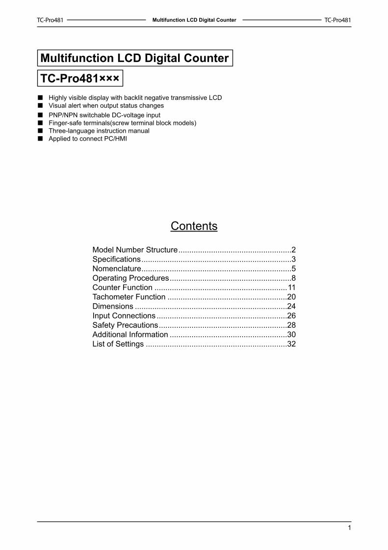
Multifunction LCD Digital Counter
Multifunction LCD Digital Counter
TC-Pro481×××Highly visible display with backlit negative transmissive LCDVisual alert when output status changesPNP/NPN switchable DC-voltage inputFinger-safe terminals(screw terminal block models)Three-language instruction manualApplied to connect PC/HMI
Contents
Model Number Structure ....................................................2Specifications .....................................................................3Nomenclature .....................................................................5Operating Procedures ........................................................8Counter Function .............................................................11Tachometer Function .......................................................20Dimensions ......................................................................24Input Connections ............................................................26Safety Precautions ...........................................................28Additional Information ......................................................30List of Settings .................................................................32
■■
■■■■

�
Multifunction LCD Digital Counter
Model Number Structure
List of Models
Output type Supply voltageModel
Standard Communication
Contact output 100~�40 VAC TC-Pro481SRA (-D) TC-Pro481CRA (-D)�4 VDC/�4 VAC TC-Pro481SRD (-D) TC-Pro481CRD (-D)
Transistor output 100~�40 VAC TC-Pro481STA (-D) TC-Pro481CTA (-D)�4 VDC/�4 VAC TC-Pro481STD (-D) TC-Pro481CTD (-D)
Note: The model with communication must be used with cable.
Model Number Legend
TC-Pro 481 -1 2 3 4
Accessories (Order Separately)
Name Models9-pin Female D-sub cable for RS-�3� connector, 1.5m Cable CAB-090A�3�9-pin Female D-sub cable for RS-485 connector, 1.5m Cable CAB-090A4859-pin Female D-sub cable for RS-4�� connector, 1.5m Cable CAB-090A4��
9-pin male D-sub adapter for CAB-090A�3�/CAB-090A485/CAB-090A4�� ADP-090401
9-pin Female D-sub cable for RS-�3� connector, 1.5m Cable CAB-090B�3�9-pin Female D-sub cable for RS-485 connector, 1.5m Cable CAB-090B4859-pin Female D-sub cable for RS-4�� connector, 1.5m Cable CAB-090B4��
Mounting Track 0F-APanel Protective Cover SVF-A
Communication Protective Cover TTL-11
Note:CAB-090A�3�/485/4�� is used for Flush mounting products CAB-090B�3�/485/4�� is used for DIN track mounting products
■
■
■
CommunicationS: Standard (no communication)C: Communication
Output typeR: ContactT: Transistor
1.
2.
Supply voltageA: 100V~�40VAC D: �4VDC、�4VAC
Mounting methodNone: Flush mounting D: DIN track mounting
3.
4.

3
Multifunction LCD Digital Counter
Specifications Ratings
Item TC-Pro481□□□-□Classification Digital counter
Supported configurations
�-stage counter, 2-stage counter, total counter, batch counter, dual counter, and tachometer (selectable)
Rated supply voltage �00~240VAC (50/60Hz), 24VAC (50/60Hz),24VDC (permissible ripple:20% (p-p) max.)Operating voltage
range 85% to ��0% rated supply voltage (24VDC; 90% to ��0%)
Power consumptionApprox. 6.2VA at 264VAC,Approx. 5.�VA at 26.4VAC,Approx. 2.4W at 24VDC
Mounting method Flush mounting, DIN track mountingExternal connections Screw terminals
Terminal screw tightening torque 0.5 N•m Max.
Display7-segment, LCD displayPresent value: 9-mm-high characters, whiteSet value: 4-mm-high characters, white
Digits 6 digits, PV/SV (-99,999~999,999)Input signals CP�, CP2, Reset �, Reset 2
Max. counter speed 30Hz or 5KHz (�0KHz for tachometer) selectable, ON/OFF ratio �:�, common setting for CP� and CP2
Input mode Increment, decrement, command, individual, and quadrature
Input method
No-voltage input/voltage input (switchable)No-voltage inputON impedance: 1kΩ max. (leakage current: 5~20 mA at 0Ω)ON residual voltage: 3V max.OFF impedance: 100kΩ min.Voltage InputHigh (logic) level: 4.5 to 30 VDCLow (logic) level: 0 to 2 VDC(Input resistance: approx. 4.7 kΩ)
※◆
◆
Reset input Minimum reset input signal width: � or 20ms(selectable), common setting for all inputsReset system External, manual, and automatic reset (internal according to C,R,P, and Q mode operation)Output modes N,F,C,R,K-�,P,Q,A,K-2,D,L,H
One-shot output time 0000.0�~9999.99sOutput method Relay/transistor output
Control output
SPDT contact output: 5A at 250 VAC, resistive load (cosФ=1)Minimum applied load: �0 mA at 5 VDC (failure level: P, reference value)Transistor output: NPN open collector, max. �00mA at 30 VDCResidual voltage: �.5 VDC max. (approx. �V)Output category according to EN60947-5-� for timers with Contact outputs(AC-�5; 250V 3A / AC-�3; 250V 5A / DC-�3; 30V 0.5A)Output category according to EN60947-5-2 for timers with Transistor outputs(DC-�3; 30V �00 mA)NEMA B300 Pilot Duty, �/4 HP 5-A resistive load at �20 VAC, �/3 HP 5-A resistive load at 240 VAC
External power supply �2VDC (�5%), 80mAKey protection Yes
Prescaling function Yes (000.00�~999.999) Decimal point
adjustment Yes (rightmost 3 digitals)
Sensor waiting time Approx. 250 ms (control output is turned OFF and no input is accepted during sensor waiting time)
Memory backup EEPROM (overwrites: �00,000 times min.) that can store data for �0 years min.
Ambient temperature Operating: -�0 to 55°C (with no icing or condensation)Storage: -25 to 65°C (with no icing or condensation)
Ambient humidity 25% to 85%Case color Flush mode: black, DIN track mode: gray-black
Attachments Waterproof packing, flush mounting adapter
■
4
Multifunction LCD Digital Counter
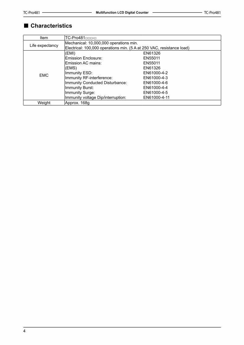
Characteristics
Item TC-Pro481□□□-□
Life expectancy Mechanical: �0,000,000 operations min.Electrical: �00,000 operations min. (5 A at 250 VAC, resistance load)
EMC
(EMI) Emission Enclosure: Emission AC mains: (EMS) Immunity ESD: Immunity RF-interference: Immunity Conducted Disturbance: Immunity Burst: Immunity Surge: Immunity voltage Dip/interruption:
EN6�326EN550��EN550��EN6�326EN6�000-4-2EN6�000-4-3EN6�000-4-6EN6�000-4-4EN6�000-4-5EN6�000-4-��
Weight Approx. �68g
■

5
Multifunction LCD Digital Counter
Nomenclature
Reset Operation by Reset Key
Configuration Reset operation�-stage/2-stage
counter Resets the present value and outputs
Total counterResets the present value and outputsWhen the total count value is displayed, resets the present value, the total count value, and outputs.
Batch counterResets the present value and OUT�When the batch count value is displayed, resets the present value, the batch count value, and outputs.
Dual counter Resets the CP� present value, CP2 present value, dual count value and outputstachometer Maintains the measured value and outputs
■
Reset Indicator Control Output Indicator Present Value (character height: 9 mm) Set Value (character height: 4 mm) The First Setting Key The Second Setting Key The Third Setting Key
The Fourth Setting Key The Fifth Setting Key The Sixth Setting Key Reset Key (resets present value and output) Mode Key (changes modes and setting items) Key Protection Indicator (the preset value is OFF) Set Value (Range) A, B Display

6
Multifunction LCD Digital Counter
Block Diagram
Output circuit
Basic isolation
Display circuit
Key switch circuit
Input circuit Internal control circuit
Power supply circuit
Basic isolation
I/O Functions (Counter)
Inputs
CP�, CP2
In general (except for dual counter mode)Reads counting signalsIncrement, decrement, command, individual, and quadrature inputs accepted.When used as a dual counterReads CP� count signals with CP� input and CP2 count signals with CP2 input.Increment signals can be input.
�.
2.
Reset or Reset �
In general (except for dual counter mode)Resets present value and outputsCounting can not be performed during reset/reset � inputThe reset indicator is lit during reset input.When used as a dual counterResets CP� present valueCounting for CP� input can not be performed during reset � input.The reset indicator is lit during reset � input.
�.
2.
Total Reset or Reset 2 (see note 2.)
When used as �-stage/2-stage counterDoes not operate (Not used).When used as a total and present counterResets the total count valueHold the total count value at 0 during total reset inputWhen used as a batch counterReset the batch count value and batch output (OUT�)Holds the batch count value at 0 during total reset 2 inputWhen used as a dual counterResets the CP2 present valueCounting for CP2 input can not be performed during reset 2 input
�.
2.
3.
4.
Output Control output(OUT)
Outputs take place according to designated output mode when corresponding preset is reached.
Note:In increment mode or increment/decrement mode, the present value returns to 0, in decrement mode, the present value returns to the set value with �-stage models, and returns to set value 2 with 2-stage models.The reset indicator will not be lit when the total reset or reset 2 input is ON.
■
■
�.
2.

7
Multifunction LCD Digital Counter
I/O Functions (Tachometer)
InputsCP�, CP2 Reads counting signals. (CP2 input is not used)
RESET�, RESET2 Holds the measurement value and outputs. (CP2 input is not used)The reset indicator is lit during hold.
Outputs OUT�, OUT2 Outputs signals according to the specified output mode when a set value is reached.
■

8
Multifunction LCD Digital Counter
Operating Procedures
1-stage/2-stage/Total/Batch/Dual Counter/Tachometer Selection Mode
Run
mod
e1-
stag
e/2-
stag
e/to
tal/b
atch
/dua
l cou
nter
/tach
omet
er s
elec
tion
mod
e
Note: when the mode is changed to 1-stage/2-stage/total/ batch/dual counter/tachometer selection mode, counter will be reset.
1-stage counter setting mode(See Run Mode on page 10)
2-stage counter setting mode(See Run Mode on page 10)
Total counter setting mode(See Run Mode on page 17)
Batch counter setting mode(See Run Mode on page 17)
Dual counter setting mode(See Run Mode on page 18)
Tachometer setting mode(See Run Mode on page 19)
Power ON
See note
3s min.
See note
3s min.
■
9
Multifunction LCD Digital Counter
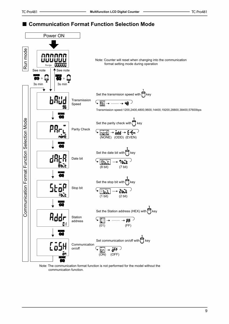
Communication Format Function Selection Mode
Power ON
See note
3s min
See note
3s min
Note: Counter will reset when changing into the communication format setting mode during operation
Transmission Speed
Parity Check
Date bit
Stop bit
Stationaddress
Communicationon/off
Set the transmision speed with key
Set the parity check with key
Set the date bit with key
Set the stop bit with key
Set the Station address (HEX) with key
Set communication on/off with key
Transmission speed:1200,2400,4800,9600,14400,19200,28800,38400,57600bps
(NONE) (ODD) (EVEN)
(8 bit) (7 bit)
(1 bit) (2 bit)
(01) (FF)
(ON) (OFF)
Note: The communication format function is not performed for the model without the communication function.
Run
mod
eC
omm
unic
atio
n Fo
rmat
Fun
ctio
n S
elec
tion
Mod
e■
�0
Multifunction LCD Digital Counter
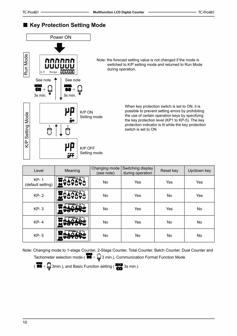
Key Protection Setting Mode
Power ON
Note: the forecast setting value is not changed if the mode is switched to K/P setting mode and returned to Run Mode during operation.
When key protection switch is set to ON, it is possible to prevent setting errors by prohibiting the use of certain operation keys by specifying the key protection level (KP1 to KP-5). The key protection indicator is lit while the key protection switch is set to ON
See note
3s min.
See note
3s min.
K/P ON Setting mode
K/P OFF Setting mode
Run
Mod
eK
/P S
ettin
g M
ode
Level Meaning Changing mode(see note)
Switching display during operation Reset key Up/down key
KP- �(default setting) No Yes Yes Yes
KP- 2 No Yes No Yes
KP- 3 No Yes Yes No
KP- 4 No Yes No No
KP- 5 No No No No
Note: Changing mode to �-stage Counter, 2-Stage Counter, Total Counter, Batch Counter, Dual Counter and
Tachometer selection mode ( 3 min.), Communication Format Function Mode
( 3min.), and Basic Function setting ( 3s min.)
■
��
Multifunction LCD Digital Counter
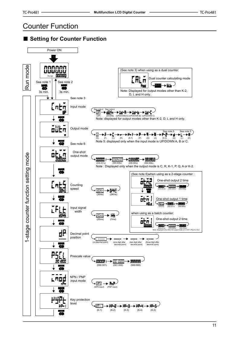
Counter Function
Setting for Counter Function
Power ON
Run
mod
e1-
stag
e co
unte
r fun
ctio
n se
tting
mod
e
See note 1 See note 2
3s min.
See note 3
See note 6
3s min.
(See note 3) when using as a dual counter:
Dual counter calculating mode
Note: Displayed for output modes other than K-2, D, L and H only.
See note 4 See note 4
Note: displayed for output modes other than K-2, D, L and H only. (UP) (DOWN) (UP/DOWN A) (UP/DOWN B) (UP/DOWN C)
Note : Displayed only when the output mode is C, R, K-1, P, Q, A or K-2.(000.001s) (000.005s) (099.990s) (999.999s)
(000.001) (001.000) (999.999)
See note 5 See note 5
Note 5: displayed only when the input mode is UP/DOWN A, B or C. (N) (F) (C) (R) (K-1) (P) (Q) (A) (K-2) (D) (L) (H)
(30Hz) (5KHz)
(20ms) (1ms)
(no decimal point) (one digit after decimal point)
(two digit after decimal point)
(three digit after decimal point)
(NPN input) (PNP input)
(K-1) (K-2) (K-3) (K-4) (K-5)
(See note 6)when using as a 2-stage counter :
when using as a batch counter:
One-shot output 2 time
One-shot output 1 time
One-shot output 2 time
Note: Displayed only when the output mode is C, R,K-1,P,Q,A or K-2.
(000.001s) (000.500s) (999.999s)
(000.001s) (000.500s) (999.999s)
(HOLD) (000.001s) (999.999s)
Input mode
Output mode
Countingspeed
Decimal pointposition
Prescale value
Key protection level
One-shotoutput mode
Input signalwidth
NPN / PNP input mode
■
�2
Multifunction LCD Digital Counter
Explanation of functions
Input mode (cntm)Set increment mode(UP)、decrement mode (DOWN)、or increment/ decrement mode (UP/DOWN A、UP/DOWN B、UP/DOWN C) as the input mode.
Dual count calculating mode (calm) When using a dual counter, select ADD (addition) or SUB (subtraction) as the calculation method for the dual count value. SUB mode can be used only when K-2, D, L or H is selected as the output mode with 6-digit models.ADD: Dual count value=CP1 PV+CP2 PVSUB: Dual count value =CP1 PV-CP2 PV
Output mode (outm)Set the way that control output for the present value is output. The possible settings are N,F,C,R,K-�,P,Q,A,K-2,D,L and H.
One-shot output 2 time (otm2)Set one-shot output time for control output (OUT2) when using as a 2-stage counter or batch counter. (000.00� to 999.999)One-shot output can be used only when C, R, K-�, P, Q, A or K-2 is selected as the output mode.
One-shot output 1 time (otm1)Set one-shot output time (000.00� to 999.999) for control output (OUT�) when using as 2-stage counter. One-shot output can be used only when D, L or H is selected as the output mode. If the output time is set to 0.00, HOLD is displayed, and outputs are held. HOLD can not be set when the output mode is K-2.
Counting speed (cnts)Set the maximum counting speed (30Hz/5KHz) for CP� and CP2 inputs together. If contacts are used for input signal, set the counting speed to 30Hz.Processing to eliminate chattering is performed for this setting.
■
Input signal width (iflt)Set Reset input signal width (20ms/�ms) for reset/reset� and total reset/reset2 inputs together. If contacts are used for input signals, set the counting speed to 20ms. Processing to eliminate chattering is performed for this setting.
Decimal point position (dp)Decide the decimal point position for the present value, CP�/CP2 present values, set value (SV�, SV2), total count value and dual count set value.
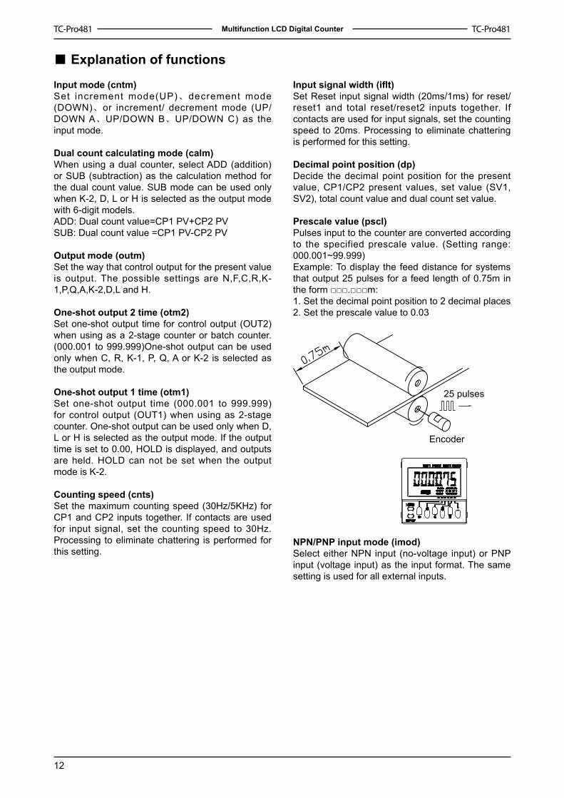
Prescale value (pscl)Pulses input to the counter are converted according to the specified prescale value. (Setting range: 000.00�~99.999)Example: To display the feed distance for systems that output 25 pulses for a feed length of 0.75m in the form □□□.□□□m: �. Set the decimal point position to 2 decimal places2. Set the prescale value to 0.03
25 pulses
Encoder
NPN/PNP input mode (imod)Select either NPN input (no-voltage input) or PNP input (voltage input) as the input format. The same setting is used for all external inputs.

�3
Multifunction LCD Digital Counter
Operation in Run Mode
Set values for each digit as required with the keys.
1-stage Counter
Present valueSet value
Present value: Shows present count valueSet value(Set value 1,2): Set the set value. When the present value reaches the set value, signals are output according the specified output mode.
Dual Counter
Dual count valueSet value for Dual counting
CP1 Present valueCP2 Present value
Dual count value: Shows the sum of the CP1 present value and the CP2 present value when the dual count calculating mode is ADD and shows the value obtained by subtracting the CP1 present value from the CP2 present value when the dual count calculating mode is SUB.
Dual count value: Set dual count value. When the dual count value reaches the dual count set value, signals are output according to the specified output mode.
CP1/ CP2 present value: Show the present count values for CP and CP2 present values respectively.
2-stage Counter
Present valueSet value 1
Present valueSet value 2
Total and forecast counter
Present valueSet value
Total count value
Present value/ Set value:Same as 1-stage counter
Total count value:Shows the present total count value
Batch Counter
Present valueSet value
Batch count valueSet value for Batch counting
Present value/ Set value: Same as 1-stage counter
Batch count value: shows the number of times the count has been completed for the present value.Batch count set value: set the batch count set value. When batch count value reaches the batch count set value, batch output (OUT1) turns ON.
■
2

�4
Multifunction LCD Digital Counter
Input Modes and Present Value (Counter)
UP (increment) Mode DOWN (decrement) mode
UP / DOWN A command input mode
UP / DOWN B individual input mode
UP / DOWN C Quadrature input mode
■
Note: If the configuration selection is set to dual count, CP� and CP2 input will operate in the same way as the count input (CP�) of UP (increment) mode. The meaning of the H and L symbols in the tables is explained below.
Input method symbol
No-voltage(NPN input)
Voltage input(PNP input)
H Short-circuit 4.5~30VDCL OPEN 0~2VDC
�.
2.

�5
Multifunction LCD Digital Counter
Input/Output Mode Setting(Counter)Operation for �-stage models is the same as that for OUT2.When using a 2-stage model as a �-stage counter, or dual counter, total and preset counter, OUT� and OUT2 turn ON and OFF simultaneously.
Output mode
UP DOWN UP/DOWN A, B, C Operation after count completion
NT h e o u t p u t s a n d present value display are held until reset/reset� is input.
F
The present value display continues to increase/decrease. The outputs are held until reset/reset� is input.
C
As soon as the count value reaches SV, the present va lue display returns to the reset start status. The present value display does not show the present value upon count-up. The outputs r e p e a t o n e - s h o t operation. OUT� self-holding output turns OFF after the OUT2 o n e - s h o t o u t p u t time. The OUT� one-s h o t o u t p u t t i m e is independent o f OUT2.
R
The present value display returns to the reset start status after the one-shot output t i m e . O U T � s e l f -holding output turns OFF after the OUT2 o n e - s h o t o u t p u t time. The OUT� one-s h o t o u t p u t t i m e is independent o f OUT2.
Note: The full scale (FS) for TC-Pro 6-digit models is 999999.When the present value reaches 999999, it returns to 0.Counting can not be performed during reset/reset� input.If reset/reset� is input while one-shot output is ON, one-shot output turns OFF.Do not use the counter function in applications where the count may be completed (again) while one-shot output is ON.
■
�.2.3.4.5.
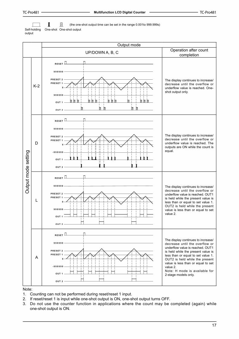
(the one-shot output time can be set in the range 0.001to 999.999s)
Self-holdingoutput
One-shot One-shot output
Out
put m
ode
setti
ng

�6
Multifunction LCD Digital Counter
Output mode
UP DOWN UP/DOWN A, B, C Operation after count completion
K-�
The present value display continues to increase/decrease. OUT� self-holding output turns OFF a f t e r t h e O U T 2 one-sho t ou tpu t t ime. The OUT� one-sho t ou tpu t time is independent of OUT2.
P
The present value display does not change during the one-sho t ou tpu t time, but the actual count returns to the reset status. The outputs return to the one-shot start state and repeat one-shot operation. OUT� self-holding output turns OFF a f t e r t h e O U T 2 one-sho t ou tpu t t ime. The OUT� one-sho t ou tpu t time is independent of OUT2.
Q
The present value c o n t i n u e s t o increase/decrease for the one-shot output t ime, but returns to the reset start status after the one-shot output time has elapsed. The outputs repeat one-shot operation. OUT� self-holding output turns OFF a f t e r t h e O U T 2 one-sho t ou tpu t t ime. The OUT� one-sho t ou tpu t time is independent of OUT2.
A
The present value display and OUT� self-holding output is held until reset/r ese t� i s i npu t . OUT� and OUT2 are independent.
Note: The full scale (FS) for TC-Pro 6-digit models is 999999.When the present value reaches 999999, it returns to 0.Counting can not be performed during reset/reset� input.If reset/reset� is input while one-shot output is ON, one-shot output turns OFF.Do not use the counter function in applications where the count may be completed (again) while one-shot output is ON.
�.2.3.4.5.
Out
put m
ode
setti
ng
�7
Multifunction LCD Digital Counter
(the one-shot output time can be set in the range 0.001to 999.999s)Self-holdingoutput
One-shot One-shot output
Output mode
UP/DOWN A, B, C Operation after count completion
K-2The display continues to increase/decrease until the overflow or underflow value is reached. One-shot output only.
D
The display continues to increase/decrease until the overflow or underflow value is reached. The outputs are ON while the count is equal.
L
The display continues to increase/decrease until the overflow or underflow value is reached. OUT1 is held while the present value is less than or equal to set value �. OUT2 is held while the present value is less than or equal to set value 2.
A
The display continues to increase/decrease until the overflow or underflow value is reached. OUT1 is held while the present value is less than or equal to set value �. OUT2 is held while the present value is less than or equal to set value 2.Note: H mode is available for 2-stage models only.
Note: Counting can not be performed during reset/reset � input.If reset/reset � is input while one-shot output is ON, one-shot output turns OFF. Do not use the counter function in applications where the count may be completed (again) while one-shot output is ON.
�.2.3.
Out
put m
ode
setti
ng

�8
Multifunction LCD Digital Counter
Total OperationTC-Pro48� has a total counter, separate from the �-stage present counter, for counting the total accumulated value.
the total counter continues to count the total accumulated value when the present value is reset using reset/reset � input (reset key). the total count value is reset when the tota l reset / reset 2 input is turned ON. If the reset key is pressed while the total count value is reset. The present value is also reset at this time. the counting range of the total counter is -99,999 to 999,999 (-999 to 9,999). The total count value returns to 0 when i t reaches the full scale limit.
◆
◆
◆
Batch Counter Operation
TC-Pro48� has a batch counter, separate from the �-stage present counter, for counting the number of times the count value returns to 0 when it reaches the full scale limit.
The batch counter continues after count completion. Batch output is held until batch counter reset is input. When the batch counter reset input is turned ON, the batch count value is reset, and batch output turns OFF. If the reset key is pressed while the batch count value is displayed, the batch count value is displayed, the batch count value is reset and batch output turns OFF. The present value is also reset at this time.
◆
◆
◆
◆
Note: The batch count value is held at 0 during batch counter reset input. If the batch count set is 0, batch count will be performed but there will be no batch output.The batch count value returns to 0 when it reaches 999,999.Once batch input has been turned ON, it will return to the ON state after power interruptions.If the batch count set value is changed from a value that is greater than the batch count value to one that is less, batch output will turn ON.
■
■
�.2.3.4.5.

19
Multifunction LCD Digital Counter
Operation (Dual Counter)
Using the dual counter allows the count from 2 inputs to be added or subtracted and the result displayed. It is possible to specify a set value for which output turns ON when the set value matches the added or subtracted result. OUT1 and OUT2 turn ON and OFF simultaneously.
Dual Count Calculating Mode = ADDDual count value = CP1 PV + CP2 PV
Dual Count Calculating Mode = SUBDual count value = CP1 PV -CP2 PV
Note: the above is for when the output mode is N. Note: the above is for when the output mode is K-2. SUB mode can be used only when K-2, D,L or H is selected as the output mode with 6-digit models.
the operation after count completion for the dual counter value is determined by the output mode. the CP1 present value is reset when reset 1 input is turned ON and the CP2 present value is reset when reset 2 input is turned ON.if the reset key is pressed while the dual count value, CP1 present value or CP2 present value is displayed, all of the present values are reset and outputs turn OFF. At this time, counting is not possible for CP1 or CP2 input.
◆◆
◆
Note: Counting is not possible for CP1 during reset 1 input. CP2 will not be affected. The dual count value will be calculated based on a CP1 present value of 0. Counting is not possible for CP2 during reset 2 input. CP1 will not be affected. The dual count value will be calculated based on a CP2 present value of 0.The counting range for dual count value is -99,999 to 999,999.
Reset Function List
Function 1-stage/2-
stage counter
Total counter Batch counter Dual counter
Screen displayed in run mode
Present value/set value(1,2)
Present value/set
value
Total count value
Present value/set
value
Batch count value/ batch
count set value
Dual count value/dual count set
value
CP1 present value/ CP2
present value
Reset/reset 1
Present value and
output reset
Present value and output reset
Present value and output reset
Only the CP1 present value is reset
Total reset/reset 2 No effect Only the total count value
is resetBatch count value and
batch output reset.Only the CP2 present
value is reset
Reset keyPresent
value and output reset
Present value and
output reset
Present value, total count value, and output
reset
Present value and
output reset
Present value, batch count value, output and
batch output reset.
CP1 present value, CP2 present value, dual count value, and output reset.
■
1.
2.
1.
2.
3.
■

20
Multifunction LCD Digital Counter
Tachometer Function Power ON
Run
mod
eFu
nctio
n se
tting
mod
e
See note 1
3s min.
See note 2
3s min.
For details on operation in run mode, refer to page 22.Note: 1. If the mode is switched to the tachometer function setting mode during operation, operation will continue. 2. Changes made to settings in function setting mode are enabled for the first time when the mode is changed to run mode. Also, when settings are changed, the counter is reset (measured value initialized and output turned OFF) on returning to run mode.
The characters displayed in reverse video are the initial values.
Set each setting item with the Key.
(30Hz) (10KHz)
(no decimal point) (one digit after decimal point)
(two digit after decimal point)
(three digit after decimal point)
(000.001s) (001.000s) (999.999s)
( No averageprocessing )
( Average of 2measurements )
( Average of 4measurements )
( Average of 8measurements )
(00.01s) (99.99s)
(00.00s) (99.99s)
(KP-1) (KP-2) (KP-3) (KP-4) (KP-5)
(NPN input) (PNP input)
Output mode
Countingspeed
Decimal point position
Prescale value
Average processing
Auto-zero time
Startup time
NPN / PNP input mode
Key protectlevel
(HI-LO) (no range) (HI-HI) (LO-LO)

2�
Multifunction LCD Digital Counter
Tachometer output mode (totm)Set the output method for control output based on the OUT�/OUT2 set value. Upper and lower limit (HI-LO), area (AREA), upper (HI-HI),and lower limit (LO-LO) can be set.
Counting speed (cnts) Set the maximum counting speed (30Hz/�0KHz) for CP� input. If contacts are used for input signals, set the counting speed to 30Hz. Processing to eliminate chattering is performed for this setting.
Decimal point position (dp)Decide the dec imal po in t pos i t ion for the measurement value, OUT� set value, and OUT2 set value.
Prescale value (pscl)It is possible to display the rate of rotation or the speed of a device or machine to which the TC-Pro48� is mounted by converting input pulses to a desired unit. If this prescaling function is not used, the input frequency (Hz) will be displayed.The relationship between display and input is determined by the following equation. Set the prescale value according to the unit to be displayed.Displayed value=input pulse frequency×prescale value
�. Displaying rotation rateDisplay unit Prescale value
rpm �/N*60rps �/N
N: number of pulses per revolutionExample: in order to display the rate of rotation for a machine that outputs �0 pulses per revolution in the form □□□.□□□rpm:�. Set the decimal point position to 3 decimal place2. Using the formula, set the prescale value to 6.
2. Displaying speedDisplay unit Prescale value
m/min πd*1/N*60m/s πd*1/N
N: number of pulses per revolutiond: diameter of rotating bodyπd: circumference
Average processing (aug)Flickering display and output chattering can be prevented using average processing (simple averaging). Average processing can be set to one of four levels: no average processing, 2 times (i.e., the average of 2 measurement values), 4 times, 8 times. The measurement cycle will be equal to the sampling cycle (�00ms) multiplied by the average processing setting (i.e., the number of time). Average processing enables fluctuating input signals to be displayed stably. Set the optimum number of times for the application.
Auto-zero time (autz)It is possible to set the TC-Pro48� so that if there is no pulse for a certain time the display is force-set to 0. This time is called the auto-zero time. Set the auto-zero time to a time slightly longer than the estimated interval between input pulses and within the setting range (00.0�~99.99s).It will not be possible to make accurate measurements if the auto-zero time is set to a time shorter than the input pulse cycle. Setting a time that is too long may also result in problems, such as a time-lag between rotation stopping and the alarm turning ON.
Startup time (stmr)In order to prevent undesired output resulting from unstable input immediately after the power supply is turned ON, it is possible to prohibit measurement for a set time (00.00~99.99s), the startup time. It can also be used to stop measurement and disable output until the rotating body reaches the normal rate of rotation, after the power supply to the TC-Pro48� and rotating body are turned ON at the same time.
Display
Startup time
Time
Comparison value(lower limit)
Power supply
Output(lower limit)
NPN/PNP input mode (imod) Select either NPN input (no-voltage input) or PNP input (voltage input) as the input format. The same setting is used for all external inputs.
Explanation of Tachometer Functions■
22
Multifunction LCD Digital Counter
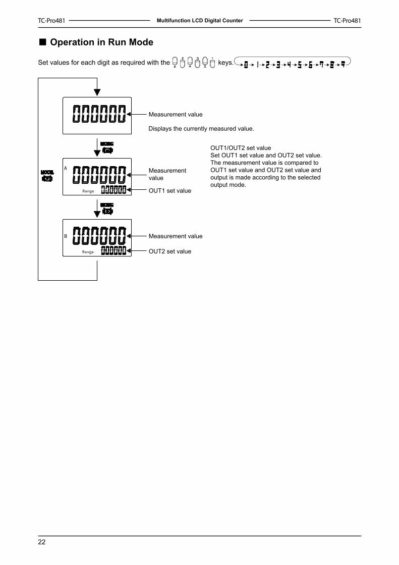
Operation in Run Mode
Set values for each digit as required with the keys.
Measurement value
Measurementvalue
OUT1 set value
Measurement value
OUT2 set value
Displays the currently measured value.
OUT1/OUT2 set valueSet OUT1 set value and OUT2 set value. The measurement value is compared to OUT1 set value and OUT2 set value and output is made according to the selected output mode.
■

23
Multifunction LCD Digital Counter
Output Mode Settings (Tachometer)
Upper and lower limit(HI-LO)
(upper-limit)OUT2 set value
(Lower-limit)OUT1 set value
Measurement value
ON condition for OUT1: measurement value≤OUT1 set valueON condition for OUT2: measurement value≥OUT2 set value
Area (AREA)
OUT2 set value
OUT1 set value
Measurement value
ConditionON condition for OUT1ON condition for OUT2
Measurement value<OUT1 set valueMeasurement value >OUT2 set value
OUT set value≤Measurement value≤OUT2 set value
OUT1 set value≤OUT2 set value
Measurement value <OUT2 set valueMeasurement value >OUT1 set value
OUT2 set value≤Measurement value≤OUT1 set value
OUT1 set value >OUT2 set value
(Upper-limit)
(HI-HI)
(Upper-limit)OUT2 set value
(Lower-limit)OUT1 set value
Measurement value
ON condition for OUT1: measurement value≥OUT1 set valueON condition for OUT2: measurement value≥OUT2 set value
(Lower-limit)
(LO-LO)
(Upper-limit)OUT2 set value
(Lower-limit)OUT1 set value
Measurement value
ON condition for OUT1: Measurement value≤OUT1 set valueON condition for OUT2: Measurement value≤OUT2 set value
■O
utpu
t mod
e se
tting

24
Multifunction LCD Digital Counter
Dimensions Note: all units are in millimeters unless otherwise indicated.
Dimensions without Flush Mounting Adapter
Note: M3 terminal screw (effective length: 8mm)
Dimensions with Flush Mounting Adapter
Panel Cutouts
>
>> Note: The mounting panel thickness should be �.5 mm.To allow easier operability, it is recommended that adapters are mounted so that the gap between sides with hooks is at least 20mm.
�.2.

25
Multifunction LCD Digital Counter
Dimensions Note: all units are in millimeters unless otherwise indicated.
Dimensions without DIN Track Mounting Adapter
Note: M3 terminal screw (effective length: 8mm)
Dimensions without DIN Track Mounting Adapter (with communication)

26
Multifunction LCD Digital Counter
Installation & Accessories
160mm
Cable: CAB - 090A□□□(order separately)
160mm
Cable: CAB - 090B□□□(order separately)
Waterproof Packing Flush Mounting Adapter End Plate CABC-44 Mounting Track PR-43 BK-6 0F-A (order separately)
ADP-09040� apdater changing 4 into 9 PIN Panel Protective Cover Communication Protective Cover(special between 232, 485 and 422, SVF-A TTL-��order separately) (order separately) (order separately)
�60cm
�60cm

27
Multifunction LCD Digital Counter
Input Connections
Signal, Reset, and Gate Input No-voltage Input Signal Levels
Internal circuit
No-voltage Inputs (NPN Input)
Open Collector (connection to NPN open collector output sensor)
Gate CP1
Reset 2
Reset 1
Signal CP2External voltage +
External voltage -
When SW is pressed, the transistor is ON that shows the input has response.
Voltage Inputs (connection to a voltage output sensor)
Gate CP1
Reset 2
Reset 1
Signal CP2
External voltage +
External voltage -
When SW is pressed, the transistor is ON that shows the input has response.
Contact Input
Gate CP1
Reset 2
Reset 1
Signal CP2
SW is pressed, that shows input the input has response.
No-contact input
Short-circuit levelTransistor ONResidual voltage: 3V max.Impedance when ON: 1KΩ min.(the leakage current is 5 to 20 mA when the impedance is 0 Ω )Open levelTransistor OFFImpedance when OFF: 100KΩ min.
Contact inputUse contact which can adequately switch 5 mA at �0V. The DC voltage must be 30VDC.
28
Multifunction LCD Digital Counter
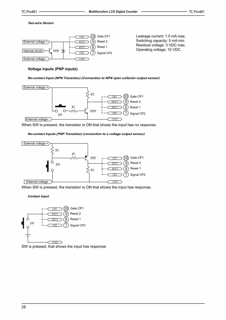
Two-wire Sensor
Gate CP1
Reset 2
Reset 1
Signal CP2
Leakage current: 1.5 mA max.Switching capacity: 5 mA min.Residual voltage: 3 VDC max.Operating voltage: 10 VDC
External voltage +
External voltage -
Internal circuit
Voltage inputs (PNP inputs)
No-contact Input (NPN Transistor) (Connection to NPN open collector output sensor)
Gate CP1
Reset 2
Reset 1
Signal CP2
External voltage +
External voltage -
When SW is pressed, the transistor is ON that shows the input has no response.
No-contact Inputs (PNP Transistor) (connection to a voltage output sensor)
Gate CP1
Reset 2
Reset 1
Signal CP2
External voltage +
External voltage -
When SW is pressed, the transistor is ON that shows the input has response.
Contact Input
Gate CP1
Reset 2
Reset 1
Signal CP2
SW is pressed, that shows the input has response.
29
Multifunction LCD Digital Counter
Safety Precautions Caution
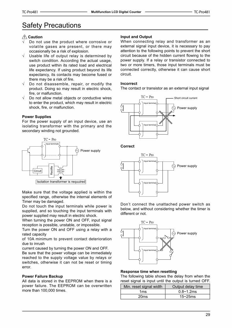
Do not use the product where corrosive or volati le gases are present, or there may occasionally be a risk of explosion. Usable life of output relay is determined by switch condition. According the actual usage, use product within its rated load and electrical life expectancy. If using product beyond its life expectancy, its contacts may become fused or there may be a risk of fire. Do not disassemble, repair, or modify the product. Doing so may result in electric shock, fire, or malfunction.Do not allow metal objects or conductive wires to enter the product, which may result in electric shock, fire, or malfunction.
Power Supplies For the power supply of an input device, use an isolating transformer with the primary and the secondary winding not grounded.
Input terminals
Power supply
Circuit
Rec
tifie
Isolation transformer is requuired
Make sure that the voltage applied is within the specified range, otherwise the internal elements of Timer may be damaged.Do not touch the input terminals while power is supplied, and so touching the input terminals with power supplied may result in electric shock.When turning the power ON and OFF, input signal reception is possible, unstable, or impossible. Turn the power ON and OFF using a relay with a rated capacity of �0A minimum to prevent contact deterioration due to inrushcurrent caused by turning the power ON and OFF. Be sure that the power voltage can be immediately reached to the supply voltage value by relays or switches, otherwise it can not be reset or timing error.
Power Failure Backup All data is stored in the EEPROM when there is a power failure. The EEPROM can be overwritten more than �00,000 times.
√
√
√
√
Input and OutputWhen connecting relay and transformer as an external signal input device, it is necessary to pay attention to the following points to prevent the short circuit because of the hidden current flowing to the power supply. If a relay or transistor connected to two or more timers, those input terminals must be connected correctly, otherwise it can cause short circuit.
Incorrect The contact or transistor as an external input signal
Input terminal
Input terminal
Power supply
Short circuit current
Correct
Input terminal
Input terminal
Power supply
Don’t connect the unattached power switch as below, and without considering whether the timer is different or not.
Input terminal
Input terminal
Power supply
Response time when resettingThe following table shows the delay from when the reset signal is input until the output is turned OFF.
Min. reset signal width Output delay time�ms 0.8~�.2ms20ms �5~25ms

30
Multifunction LCD Digital Counter
Transistor OutputThe transistor output of TC-Pro is insulated from the internal circuitry by a photocoupler, so the transistor output can be used as both NPN and PNP output.The diode connected to the collector of the output transistor is used to absorb inverted voltage that is generated when an inductive load is connected to TC- Pro.The transistor output of TC-Pro is insulated from the internal circuitry by a photocoupler, so the transistor output can be used as both NPN and PNP output.The diode connected to the collector of the output transistor is used to absorb inverted voltage that is generated when an inductive load is connected to TC- Pro.
NPN output PNP output
Timer Timer
Power for load Power for load
Inducted load
Changing the set values When changing the set value during a timing operation, the output will turn ON if the set value is changed as follows because of the use of a constant read-in system:Elapsed time(up) mode: present value≥set valueRemaining time(DOWN) mode: elapsing time≥ set value(the present value is set to 0)Note: when in the remaining time mode, the amount the set value is changed is added to or subtracted from the present value.
Connection Make sure that wiring is correct.
MountingTighten two mounting screws on the adapter. Tighten them alternately, a little at a time, so as to keep them at an equal tightness. TC-Pro panel surface is water-resistant. In order to prevent the internal circuit from water penetration through the space between the TC-Pro and operating panel, attach a waterproof packing between TC-Pro and installation panel and secure the waterproof packing with the BK-62 flush-mounting adapter.
Operation environmentUse the product within the rating specified for submerging in water and exposure to oil.Do not use in location affected by excessive vibration or shockDo not use the product in locations subject to dust, corrosive gases, or direct sunlight.Separate the input signal devices, input signal cables, and the product from the source of noise or high-tension cables producing noise.Separate the product from the source of static electricity when using the product in an environment where a large amount of static electricity is produced (e.g. forming compounds, powders, or fluid materials being transported by pipe). Organic solvents (such as paint thinner), as well as very acidic or basic solutions might damage the outer casing of the TC-Pro. Use the product within the rating specified for temperature and humidity.Do not use the product in locations where condensation may occur due to high humidity or where temperature changes are severe.S to re a t the spec i f ied tempera tu re . I f TC-Pro has been stored at a temperature of less than -�0℃, allow TC-Pro to stand at room temperature for at least 3 hours before use.
Note: auxiliary relay (e.g. MY relay)
InsulationThere is basic insulation between power supply and output terminals. Input and output terminals are connected to devices without exposed charged parts. Input and output terminals are connected to devices with basic insulation that is suitable for the maximum operating voltage.
√
√
√
√
√
√
√
√
√
3�
Multifunction LCD Digital Counter
Additional Information (Using the operation keys)
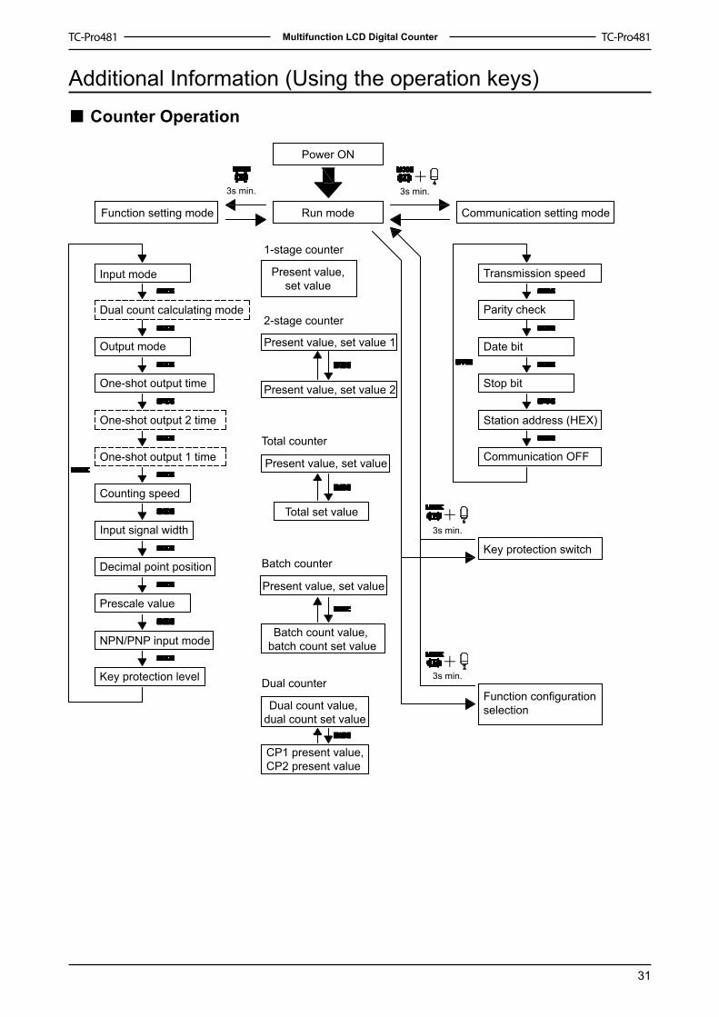
Counter Operation
Communication OFF
Key protection switch
Function configuration selection
Station address (HEX)
Stop bit
Date bit
Input mode
Dual count calculating mode
Output mode
One-shot output time
One-shot output 2 time
One-shot output 1 time
Counting speed
Input signal width
Decimal point position
Prescale value
NPN/PNP input mode
Key protection level
Parity check
Transmission speed
Power ON
Run modeFunction setting mode Communication setting mode
Present value, set value
Present value, set value 1
Present value, set value 2
Present value, set value
Total set value
1-stage counter
2-stage counter
Total counter
Batch counter
Dual counter
Present value, set value
Batch count value, batch count set value
Dual count value, dual count set value
CP1 present value,CP2 present value
3s min. 3s min.
3s min.
3s min.
■

32
Multifunction LCD Digital Counter
Tachometer Operation
Power ON
Run modeFunction setting mode
Measurement value
Measurement valueOUT1 set value
Measurement valueOUT2 set value
Tachometer output mode
Counting speed
Decimal point position
Prescale value
Average processing
Auto-zero time
Startup time
Key protection level
NPN/PNP input mode
Communication setting mode
Communication OFF
Station address (HEX)
Stop bit
Date bit
Parity check
Transmission speed
Key protection switch
Function configuration selection
3s min.
3s min.
3s min. 3s min.
■
33
Multifunction LCD Digital Counter
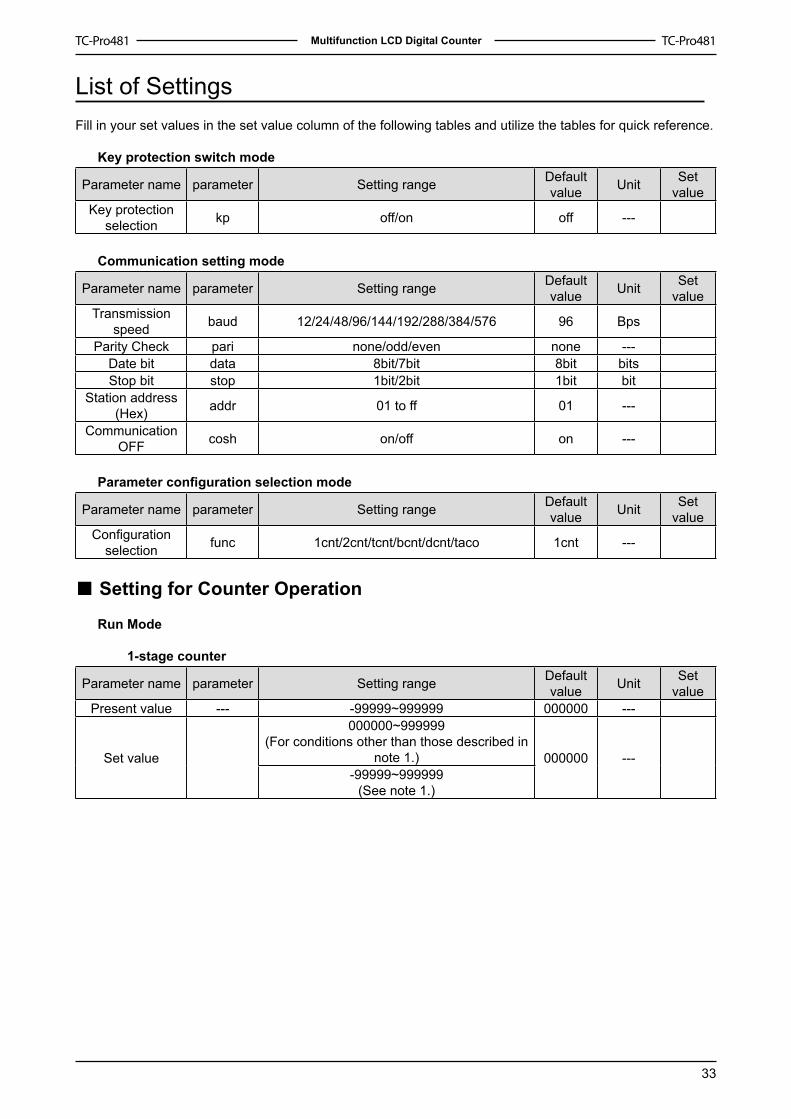
List of Settings Fill in your set values in the set value column of the following tables and utilize the tables for quick reference.
Key protection switch mode
Parameter name parameter Setting range Default value Unit Set
valueKey protection
selection kp off/on off ---
Communication setting mode
Parameter name parameter Setting range Default value Unit Set
valueTransmission
speed baud �2/24/48/96/�44/�92/288/384/576 96 Bps
Parity Check pari none/odd/even none ---Date bit data 8bit/7bit 8bit bitsStop bit stop �bit/2bit �bit bit
Station address (Hex) addr 0� to ff 0� ---
Communication OFF cosh on/off on ---
Parameter configuration selection mode
Parameter name parameter Setting range Default value Unit Set
valueConfiguration
selection func �cnt/2cnt/tcnt/bcnt/dcnt/taco �cnt ---
Setting for Counter Operation
Run Mode
1-stage counter
Parameter name parameter Setting range Default value Unit Set
valuePresent value --- -99999~999999 000000 ---
Set value
000000~999999(For conditions other than those described in
note �.) 000000 ----99999~999999
(See note �.)
■

34
Multifunction LCD Digital Counter
2-stage counter
Parameter name parameter Setting range Default value Unit Set
value
Screen �
Present value --- -99999~999999
000000 ---Set value � ---
000000~999999(For conditions other than those described in
note �.)-99999~999999
(See note �.)
Screen 2
Present value --- -99999~999999
000000 ---Set value 2 ---
000000~999999(For conditions other than those described in
note �.)-99999~999999
(See note �.)
Total and preset counter
Parameter name parameter Setting range Default value Unit Set
value
Screen �
Present value --- -99999~999999
000000 ---Set value � ---
000000~999999(For conditions other than those described in
note �.)-99999~999999
(See note �.)
Screen 2
Total count value
--- -99999~999999 000000 ---
Batch counter
Parameter name parameter Setting range Default value Unit Set
value
Screen �
Present value --- -99999~999999
000000 ---Set value ---
000000~999999(For conditions other than those described in
note �.)-99999~999999
(See note �.)
Screen 2
Batch count value
--- 000000~999999
000000 ---Batch count
set value
--- 000000~999999
35
Multifunction LCD Digital Counter
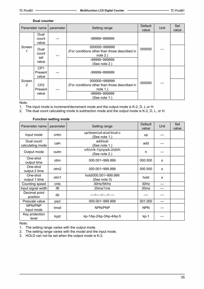
Dual counter
Parameter name parameter Setting range Default value Unit Set
value
Screen �
Dual count value
--- -99999~999999
000000 ---Dual count
set value
---
000000~999999(For conditions other than those described in
note 2.)-99999~999999
(See note 2.)
Screen 2
CP�Present value
--- -99999~999999
000000 ---CP2Present value
---
000000~999999(For conditions other than those described in
note �.)-99999~999999
(See note �.)Note:
The input mode is increment/decrement mode and the output mode is K-2, D, L or H.The dual count calculating mode is subtraction mode and the output mode is K-2, D, L, or H.
Function setting mode
Parameter name parameter Setting range Default value Unit Set
value
Input mode cntm up/down/ud-a/ud-b/ud-c(See note �.) up ---
Dual count calculating mode caln add/sub
(See note �.) add ---
Output mode outm n/f/c/r/k-�/p/q/a/k-2/d/l/h(See note 2.) n ---
One-shot output time otim 000.00�~999.999 000.500 s
One-shot output 2 time otm2 000.00�~999.999 000.500 s
One-shot output � time otm� hold/000.00�~999.999
(See note 3) hold s
Counting speed cnts 30Hz/5KHz 30Hz ---Input signal width iflt 20ms/�ms 20ms ---
Decimal point position dp ----/---.-/--.--/-.--- ---- ---
Prescale value pscl 000.00�~999.999 00�.000 ---NPN/PNP
Input mode imod NPN/PNP NPN ---
Key protection level kypt kp-�/kp-2/kp-3/kp-4/kp-5 kp-� ---
Note:The setting range varies with the output mode.The setting range varies with the model and the input mode.HOLD can not be set when the output mode is K-2.
�.2.
�.2.3.
36
Multifunction LCD Digital Counter
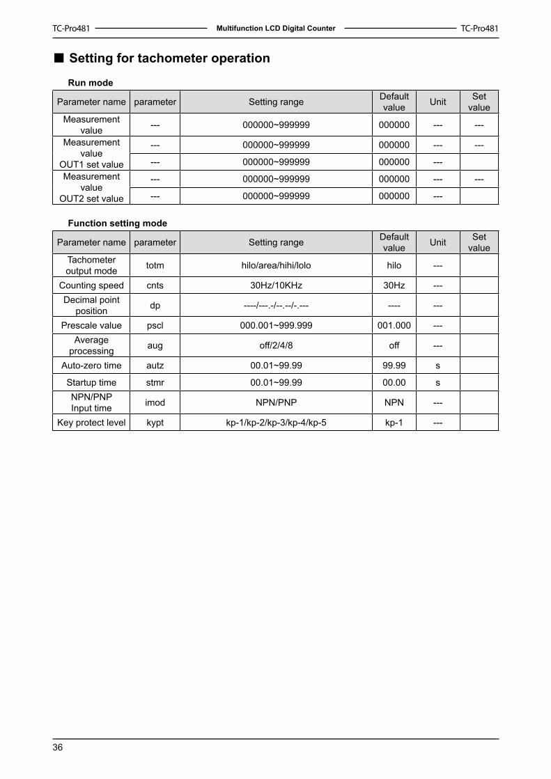
Setting for tachometer operation
Run mode
Parameter name parameter Setting range Default value Unit Set
valueMeasurement
value --- 000000~999999 000000 --- ---
Measurement value
OUT� set value
--- 000000~999999 000000 --- ---
--- 000000~999999 000000 ---Measurement
valueOUT2 set value
--- 000000~999999 000000 --- ---
--- 000000~999999 000000 ---
Function setting mode
Parameter name parameter Setting range Default value Unit Set
valueTachometer output mode totm hilo/area/hihi/lolo hilo ---
Counting speed cnts 30Hz/�0KHz 30Hz ---Decimal point
position dp ----/---.-/--.--/-.--- ---- ---
Prescale value pscl 000.00�~999.999 00�.000 ---Average
processing aug off/2/4/8 off ---
Auto-zero time autz 00.0�~99.99 99.99 s
Startup time stmr 00.0�~99.99 00.00 sNPN/PNPInput time imod NPN/PNP NPN ---
Key protect level kypt kp-�/kp-2/kp-3/kp-4/kp-5 kp-� ---
■

Comparison Table :