Embed Size (px)
Citation preview
BRKCRS - 2031
Multilayer Campus Architectures & Design Principles
© 2011 Cisco and/or its affiliates. All rights reserved. Cisco PublicBRKCRS-2031 2
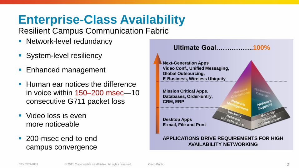
Enterprise-Class AvailabilityResilient Campus Communication Fabric
Network-level redundancy
System-level resiliency
Enhanced management
Human ear notices the difference in voice within 150–200 msec—10 consecutive G711 packet loss
Video loss is even more noticeable
200-msec end-to-end campus convergence
Next-Generation Apps
Video Conf., Unified Messaging,
Global Outsourcing,
E-Business, Wireless Ubiquity
Mission Critical Apps.
Databases, Order-Entry,
CRM, ERP
Desktop Apps
E-mail, File and Print
Ultimate Goal……………..100%
APPLICATIONS DRIVE REQUIREMENTS FOR HIGH
AVAILABILITY NETWORKING
© 2011 Cisco and/or its affiliates. All rights reserved. Cisco PublicBRKCRS-2031 3
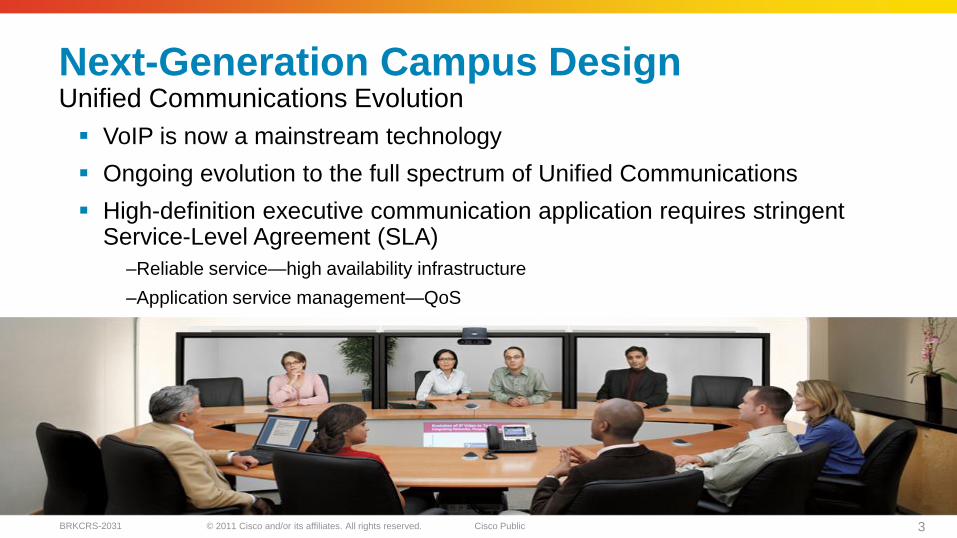
Next-Generation Campus DesignUnified Communications Evolution
VoIP is now a mainstream technology
Ongoing evolution to the full spectrum of Unified Communications
High-definition executive communication application requires stringent Service-Level Agreement (SLA)
–Reliable service—high availability infrastructure
–Application service management—QoS
© 2011 Cisco and/or its affiliates. All rights reserved. Cisco PublicBRKCRS-2031 4
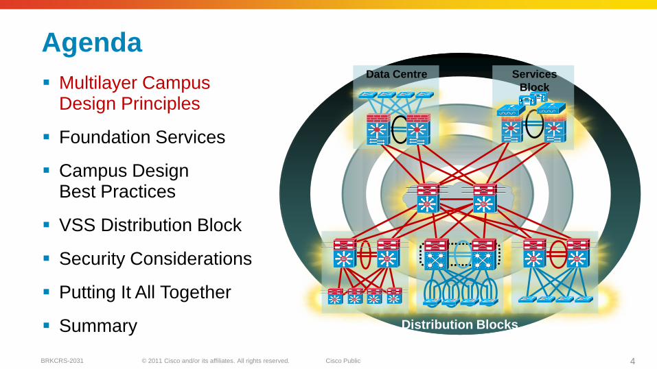
Agenda
Multilayer Campus Design Principles
Foundation Services
Campus Design Best Practices
VSS Distribution Block
Security Considerations
Putting It All Together
Summary
SiSiSiSi
SiSiSiSi
SiSi
Data Centre
SiSi SiSi
Services
Block
Distribution Blocks
SiSi SiSi SiSi
© 2011 Cisco and/or its affiliates. All rights reserved. Cisco PublicBRKCRS-2031 5
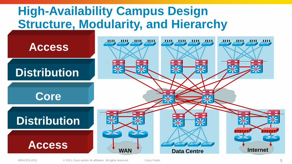
Data CentreWAN Internet
SiSi SiSi SiSi SiSi SiSi SiSi
SiSi SiSi
SiSi SiSi
SiSi SiSiSiSi
SiSi
Access
Core
Distribution
Distribution
Access
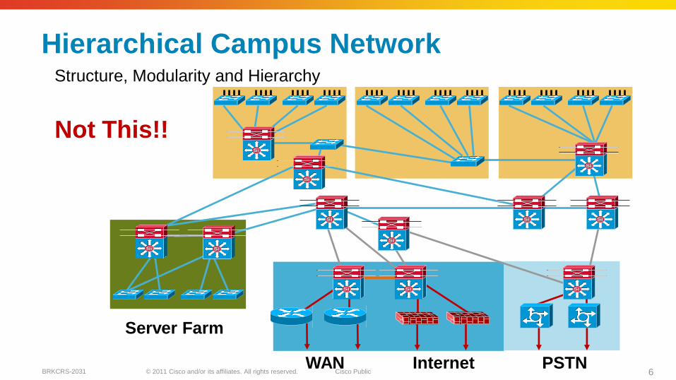
High-Availability Campus DesignStructure, Modularity, and Hierarchy
© 2011 Cisco and/or its affiliates. All rights reserved. Cisco PublicBRKCRS-2031 6
Hierarchical Campus Network
Server Farm
WAN Internet PSTN
SiSi
SiSi
SiSi SiSi
SiSi SiSi SiSi
SiSi
SiSi SiSi SiSi
SiSi
Not This!!
Structure, Modularity and Hierarchy
© 2011 Cisco and/or its affiliates. All rights reserved. Cisco PublicBRKCRS-2031 7
SiSi SiSi
SiSiSiSi
SiSi SiSi
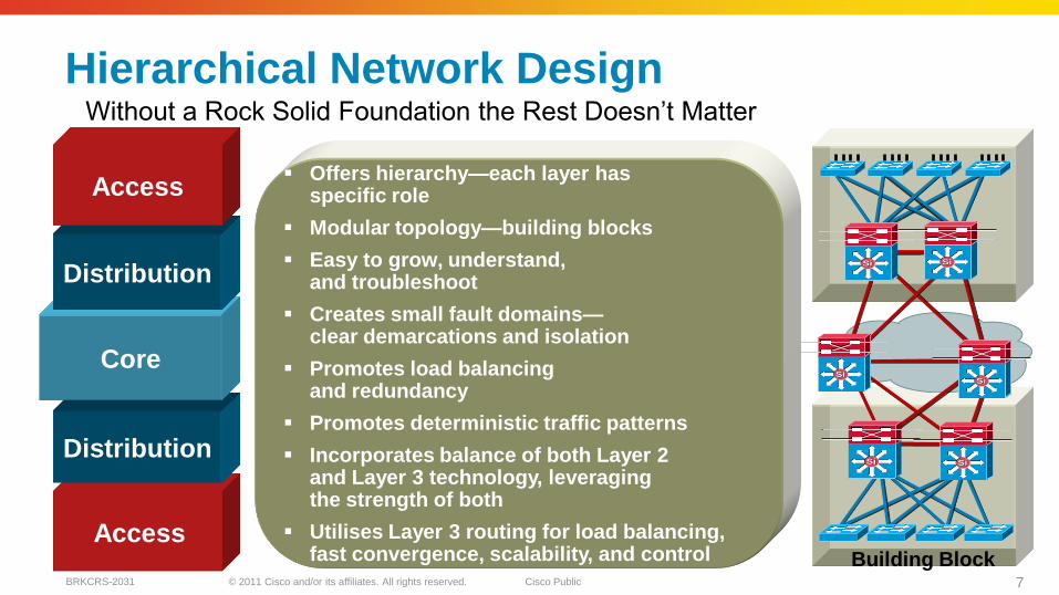
Hierarchical Network Design
Building BlockAccess
Distribution
Core
Distribution
Access Offers hierarchy—each layer has
specific role
Modular topology—building blocks
Easy to grow, understand, and troubleshoot
Creates small fault domains—clear demarcations and isolation
Promotes load balancing and redundancy
Promotes deterministic traffic patterns
Incorporates balance of both Layer 2and Layer 3 technology, leveraging the strength of both
Utilises Layer 3 routing for load balancing, fast convergence, scalability, and control
Without a Rock Solid Foundation the Rest Doesn’t Matter
© 2011 Cisco and/or its affiliates. All rights reserved. Cisco PublicBRKCRS-2031 8
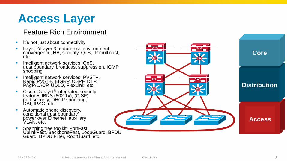
Access Layer
It’s not just about connectivity
Layer 2/Layer 3 feature rich environment; convergence, HA, security, QoS, IP multicast, etc.
Intelligent network services: QoS,trust boundary, broadcast suppression, IGMPsnooping
Intelligent network services: PVST+, Rapid PVST+, EIGRP, OSPF, DTP, PAgP/LACP, UDLD, FlexLink, etc.
Cisco Catalyst® integrated security features IBNS (802.1x), (CISF): port security, DHCP snooping, DAI, IPSG, etc.
Automatic phone discovery, conditional trust boundary, power over Ethernet, auxiliary VLAN, etc.
Spanning tree toolkit: PortFast, UplinkFast, BackboneFast, LoopGuard, BPDUGuard, BPDU Filter, RootGuard, etc.
Access
Distribution
CoreSiSiSiSi
SiSi SiSi
Feature Rich Environment
© 2011 Cisco and/or its affiliates. All rights reserved. Cisco PublicBRKCRS-2031 9
SiSiSiSi
SiSi SiSi
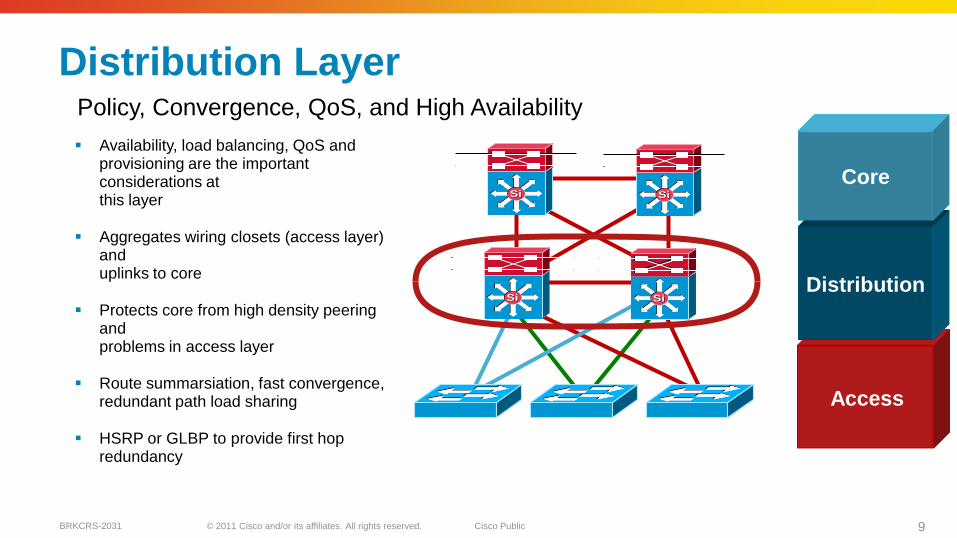
Distribution Layer
Access
Distribution
Core
Policy, Convergence, QoS, and High Availability
Availability, load balancing, QoS and provisioning are the important considerations at this layer
Aggregates wiring closets (access layer) and uplinks to core
Protects core from high density peering and problems in access layer
Route summarsiation, fast convergence, redundant path load sharing
HSRP or GLBP to provide first hop redundancy
© 2011 Cisco and/or its affiliates. All rights reserved. Cisco PublicBRKCRS-2031 10
SiSiSiSi
SiSi SiSi
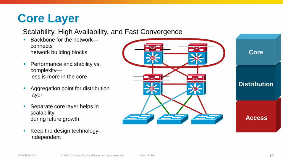
Core Layer
Backbone for the network—connects network building blocks
Performance and stability vs. complexity—less is more in the core
Aggregation point for distribution layer
Separate core layer helps in scalabilityduring future growth
Keep the design technology-independent
Access
Distribution
Core
Scalability, High Availability, and Fast Convergence
© 2011 Cisco and/or its affiliates. All rights reserved. Cisco PublicBRKCRS-2031 11
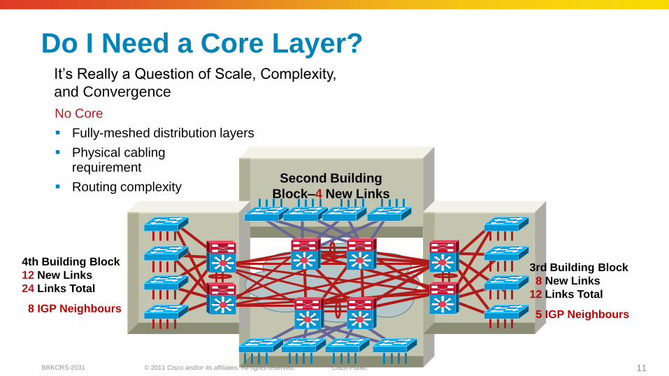
Do I Need a Core Layer?
No Core
Fully-meshed distribution layers
Physical cabling requirement
Routing complexity
4th Building Block
12 New Links
24 Links Total
8 IGP Neighbours
3rd Building Block
8 New Links
12 Links Total
5 IGP Neighbours
Second Building
Block–4 New Links
It’s Really a Question of Scale, Complexity,
and Convergence
© 2011 Cisco and/or its affiliates. All rights reserved. Cisco PublicBRKCRS-2031 12
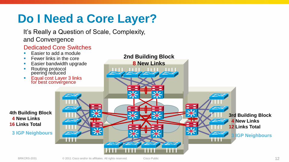
Dedicated Core Switches Easier to add a module Fewer links in the core Easier bandwidth upgrade Routing protocol
peering reduced Equal cost Layer 3 links
for best convergence
Do I Need a Core Layer?
4th Building Block
4 New Links
16 Links Total
3 IGP Neighbours
3rd Building Block
4 New Links
12 Links Total
3 IGP Neighbours
It’s Really a Question of Scale, Complexity,
and Convergence
2nd Building Block
8 New Links
© 2011 Cisco and/or its affiliates. All rights reserved. Cisco PublicBRKCRS-2031 13
Data CentreWAN Internet
SiSi SiSi SiSi SiSi
SiSi SiSi
SiSi SiSi
SiSi SiSiSiSi
SiSi
Access
Core
Distribution
Distribution
Access
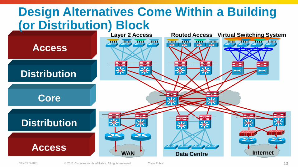
Design Alternatives Come Within a Building (or Distribution) Block
Layer 2 Access Routed Access Virtual Switching System
© 2011 Cisco and/or its affiliates. All rights reserved. Cisco PublicBRKCRS-2031 14
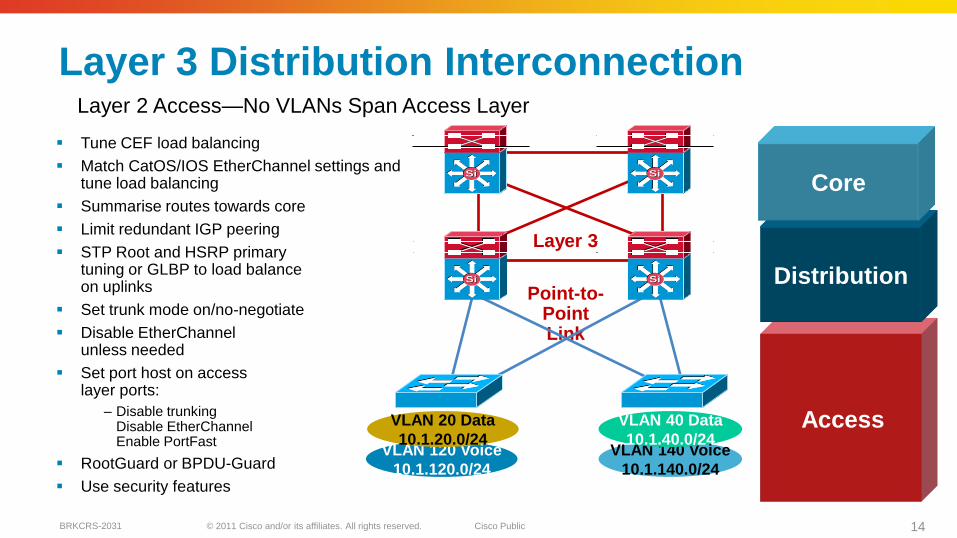
Layer 3 Distribution Interconnection
Tune CEF load balancing
Match CatOS/IOS EtherChannel settings and tune load balancing
Summarise routes towards core
Limit redundant IGP peering
STP Root and HSRP primarytuning or GLBP to load balance on uplinks
Set trunk mode on/no-negotiate
Disable EtherChannelunless needed
Set port host on access layer ports:
– Disable trunkingDisable EtherChannelEnable PortFast
RootGuard or BPDU-Guard
Use security features
Access
Distribution
Core
Layer 2 Access—No VLANs Span Access Layer
VLAN 120 Voice
10.1.120.0/24
Point-to-Point Link
VLAN 20 Data
10.1.20.0/24VLAN 140 Voice
10.1.140.0/24
SiSi SiSi
SiSi SiSi
VLAN 40 Data
10.1.40.0/24
Layer 3
© 2011 Cisco and/or its affiliates. All rights reserved. Cisco PublicBRKCRS-2031 15
VLAN 250 WLAN
10.1.250.0/24
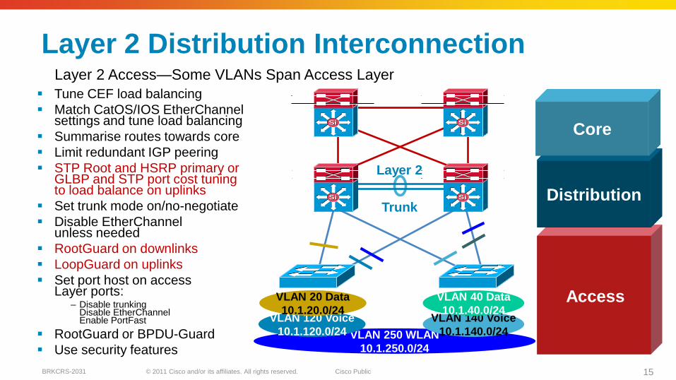
Layer 2 Distribution Interconnection
Tune CEF load balancing
Match CatOS/IOS EtherChannelsettings and tune load balancing
Summarise routes towards core
Limit redundant IGP peering
STP Root and HSRP primary or GLBP and STP port cost tuning to load balance on uplinks
Set trunk mode on/no-negotiate
Disable EtherChannelunless needed
RootGuard on downlinks
LoopGuard on uplinks
Set port host on access Layer ports:
– Disable trunkingDisable EtherChannelEnable PortFast
RootGuard or BPDU-Guard
Use security features
VLAN 120 Voice
10.1.120.0/24
Trunk
VLAN 20 Data
10.1.20.0/24VLAN 140 Voice
10.1.140.0/24
SiSi SiSi
SiSi SiSi
Layer 2
Layer 2 Access—Some VLANs Span Access Layer
VLAN 40 Data
10.1.40.0/24Access
Distribution
Core
© 2011 Cisco and/or its affiliates. All rights reserved. Cisco PublicBRKCRS-2031 16
VLAN 20 Data
10.1.20.0/24
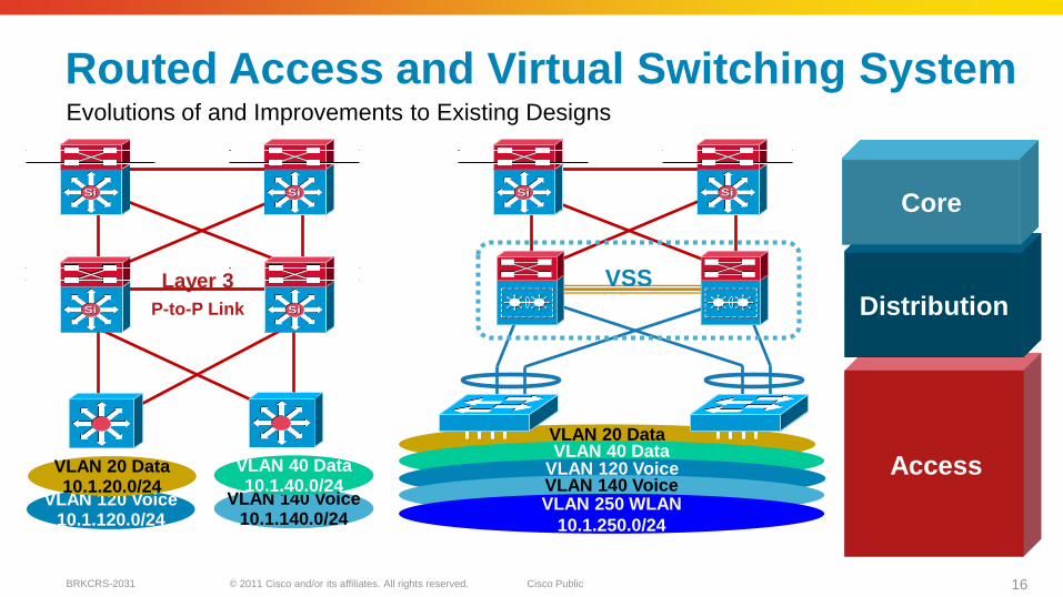
Routed Access and Virtual Switching System
VLAN 120 Voice10.1.120.0/24
P-to-P Link
Layer 3
VLAN 20 Data10.1.20.0/24
VLAN 140 Voice10.1.140.0/24
VLAN 40 Data10.1.40.0/24
SiSi SiSi
SiSi SiSi
VLAN 40 Data
10.1.40.0/24
SiSi SiSi
VLAN 120 Voice
10.1.120.0/24VLAN 140 Voice
10.1.140.0/24VLAN 250 WLAN
10.1.250.0/24
Evolutions of and Improvements to Existing Designs
Access
Distribution
Core
VSS
© 2011 Cisco and/or its affiliates. All rights reserved. Cisco PublicBRKCRS-2031 17
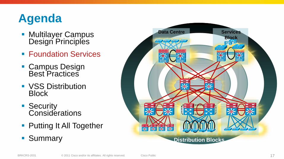
Agenda
Multilayer Campus Design Principles
Foundation Services
Campus Design Best Practices
VSS Distribution Block
Security Considerations
Putting It All Together
Summary
SiSiSiSi
SiSiSiSi
SiSi
Data Centre
SiSi SiSi
Services
Block
Distribution Blocks
SiSi SiSi SiSi
© 2011 Cisco and/or its affiliates. All rights reserved. Cisco PublicBRKCRS-2031 18
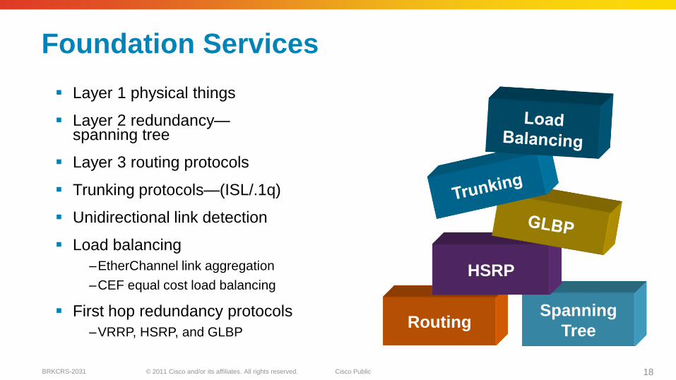
Foundation Services
Layer 1 physical things
Layer 2 redundancy—spanning tree
Layer 3 routing protocols
Trunking protocols—(ISL/.1q)
Unidirectional link detection
Load balancing
–EtherChannel link aggregation
–CEF equal cost load balancing
First hop redundancy protocols
–VRRP, HSRP, and GLBP
Spanning
TreeRouting
HSRP
© 2011 Cisco and/or its affiliates. All rights reserved. Cisco PublicBRKCRS-2031 19
Data CentreWAN Internet
Layer 3 Equal
Cost Links
Layer 3 Equal
Cost Links
SiSi SiSi SiSi SiSi SiSi SiSi
SiSiSiSi
SiSiSiSi
SiSi SiSiSiSiSiSi
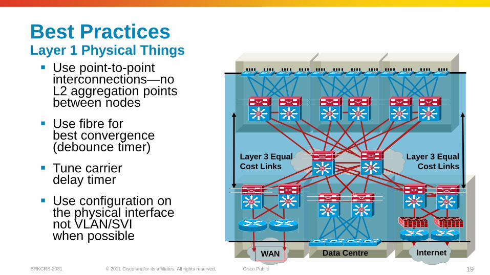
Best Practices Layer 1 Physical Things
Use point-to-point interconnections—no L2 aggregation points between nodes
Use fibre for best convergence (debounce timer)
Tune carrier delay timer
Use configuration on the physical interface not VLAN/SVI when possible
© 2011 Cisco and/or its affiliates. All rights reserved. Cisco PublicBRKCRS-2031 20
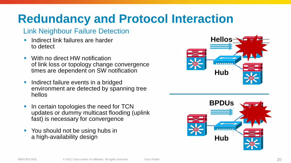
Redundancy and Protocol Interaction
Indirect link failures are harder to detect
With no direct HW notification of link loss or topology change convergence times are dependent on SW notification
Indirect failure events in a bridged environment are detected by spanning tree hellos
In certain topologies the need for TCNupdates or dummy multicast flooding (uplink fast) is necessary for convergence
You should not be using hubs in a high-availability design
SiSi
SiSi
SiSi
BPDUs
Hub
SiSi
SiSi
SiSi
Hub
HellosLink Neighbour Failure Detection
© 2011 Cisco and/or its affiliates. All rights reserved. Cisco PublicBRKCRS-2031 21
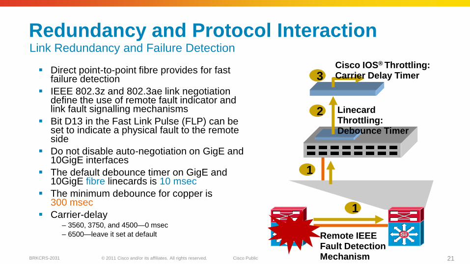
Redundancy and Protocol Interaction
Direct point-to-point fibre provides for fast failure detection
IEEE 802.3z and 802.3ae link negotiation define the use of remote fault indicator and link fault signalling mechanisms
Bit D13 in the Fast Link Pulse (FLP) can be set to indicate a physical fault to the remote side
Do not disable auto-negotiation on GigE and 10GigE interfaces
The default debounce timer on GigE and 10GigE fibre linecards is 10 msec
The minimum debounce for copper is 300 msec
Carrier-delay – 3560, 3750, and 4500—0 msec
– 6500—leave it set at default
1
2
3
Linecard Throttling: Debounce Timer
Remote IEEE Fault Detection Mechanism
Cisco IOS® Throttling: Carrier Delay Timer
SiSi SiSi
1
Link Redundancy and Failure Detection
© 2011 Cisco and/or its affiliates. All rights reserved. Cisco PublicBRKCRS-2031 22
Redundancy and Protocol Interaction
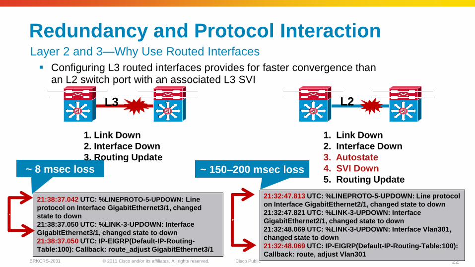
Configuring L3 routed interfaces provides for faster convergence than an L2 switch port with an associated L3 SVI
21:32:47.813 UTC: %LINEPROTO-5-UPDOWN: Line protocol
on Interface GigabitEthernet2/1, changed state to down
21:32:47.821 UTC: %LINK-3-UPDOWN: Interface
GigabitEthernet2/1, changed state to down
21:32:48.069 UTC: %LINK-3-UPDOWN: Interface Vlan301,
changed state to down
21:32:48.069 UTC: IP-EIGRP(Default-IP-Routing-Table:100):
Callback: route, adjust Vlan301
21:38:37.042 UTC: %LINEPROTO-5-UPDOWN: Line
protocol on Interface GigabitEthernet3/1, changed
state to down
21:38:37.050 UTC: %LINK-3-UPDOWN: Interface
GigabitEthernet3/1, changed state to down
21:38:37.050 UTC: IP-EIGRP(Default-IP-Routing-
Table:100): Callback: route_adjust GigabitEthernet3/1
SiSiSiSi
L2SiSiSiSi
L3
~ 8 msec loss ~ 150–200 msec loss
Layer 2 and 3—Why Use Routed Interfaces
1. Link Down
2. Interface Down
3. Autostate
4. SVI Down
5. Routing Update
1. Link Down
2. Interface Down
3. Routing Update
© 2011 Cisco and/or its affiliates. All rights reserved. Cisco PublicBRKCRS-2031 23
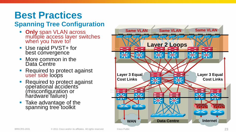
Best PracticesSpanning Tree Configuration Only span VLAN across
multiple access layer switches when you have to!
Use rapid PVST+ for best convergence
More common in the Data Centre
Required to protect against user side loops
Required to protect against operational accidents (misconfiguration or hardware failure)
Take advantage of the spanning tree toolkit
Data CentreWAN Internet
Layer 3 Equal
Cost Links
Layer 3 Equal
Cost Links
Layer 2 Loops
Same VLAN Same VLAN Same VLAN
SiSi SiSi SiSi SiSi SiSi SiSi
SiSiSiSi
SiSiSiSi
SiSi SiSiSiSiSiSi
© 2011 Cisco and/or its affiliates. All rights reserved. Cisco PublicBRKCRS-2031 24
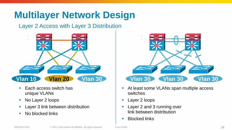
Multilayer Network Design
Each access switch hasunique VLANs
No Layer 2 loops
Layer 3 link between distribution
No blocked links
At least some VLANs span multiple access switches
Layer 2 loops
Layer 2 and 3 running over link between distribution
Blocked links
SiSi SiSi SiSi SiSi
Vlan 10 Vlan 20 Vlan 30 Vlan 30 Vlan 30 Vlan 30
Layer 2 Access with Layer 3 Distribution
© 2011 Cisco and/or its affiliates. All rights reserved. Cisco PublicBRKCRS-2031 25
0
5
10
15
20
25
30
35
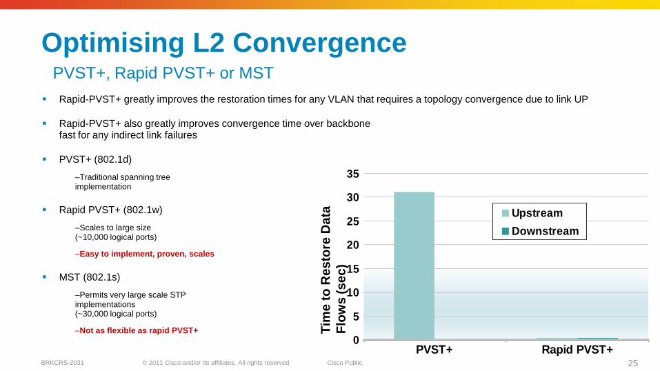
PVST+ Rapid PVST+
Upstream
Downstream
Optimising L2 Convergence
Tim
e t
o R
esto
re D
ata
Flo
ws (
se
c)
PVST+, Rapid PVST+ or MST
Rapid-PVST+ greatly improves the restoration times for any VLAN that requires a topology convergence due to link UP
Rapid-PVST+ also greatly improves convergence time over backbone fast for any indirect link failures
PVST+ (802.1d)
–Traditional spanning tree implementation
Rapid PVST+ (802.1w)
–Scales to large size (~10,000 logical ports)
–Easy to implement, proven, scales
MST (802.1s)
–Permits very large scale STPimplementations (~30,000 logical ports)
–Not as flexible as rapid PVST+
© 2011 Cisco and/or its affiliates. All rights reserved. Cisco PublicBRKCRS-2031 26
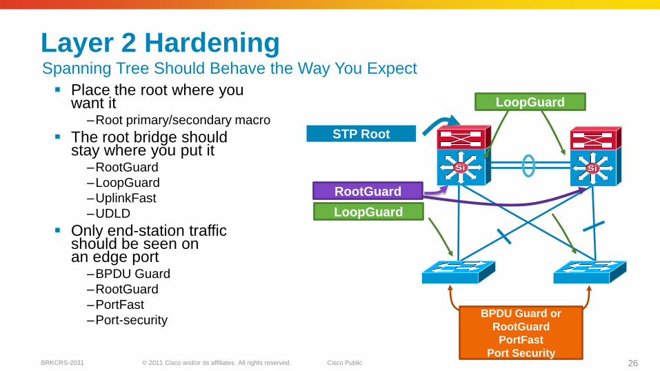
Layer 2 Hardening
Place the root where you want it
–Root primary/secondary macro
The root bridge should stay where you put it
–RootGuard
–LoopGuard
–UplinkFast
–UDLD
Only end-station traffic should be seen on an edge port
–BPDU Guard
–RootGuard
–PortFast
–Port-security
SiSiSiSi
BPDU Guard or
RootGuard
PortFast
Port Security
RootGuard
STP Root
LoopGuard
LoopGuard
Spanning Tree Should Behave the Way You Expect
© 2011 Cisco and/or its affiliates. All rights reserved. Cisco PublicBRKCRS-2031 27
Data CentreWAN Internet
Layer 3 Equal
Cost Links
Layer 3 Equal
Cost Links
SiSi SiSi SiSi SiSi SiSi SiSi
SiSiSiSi
SiSiSiSi
SiSi SiSiSiSiSiSi
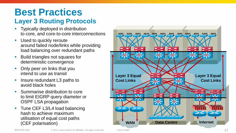
Best PracticesLayer 3 Routing Protocols Typically deployed in distribution
to core, and core-to-core interconnections
Used to quickly reroute around failed node/links while providing load balancing over redundant paths
Build triangles not squares for deterministic convergence
Only peer on links that you intend to use as transit
Insure redundant L3 paths to avoid black holes
Summarise distribution to core to limit EIGRP query diameter or OSPF LSA propagation
Tune CEF L3/L4 load balancing hash to achieve maximum utilisation of equal cost paths(CEF polarisation)
© 2011 Cisco and/or its affiliates. All rights reserved. Cisco PublicBRKCRS-2031 28
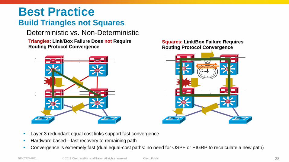
Best PracticeBuild Triangles not Squares
Layer 3 redundant equal cost links support fast convergence
Hardware based—fast recovery to remaining path
Convergence is extremely fast (dual equal-cost paths: no need for OSPF or EIGRP to recalculate a new path)
Triangles: Link/Box Failure Does not Require Routing Protocol Convergence
Model A
Squares: Link/Box Failure Requires Routing Protocol Convergence
Model B
SiSi
SiSiSiSi
SiSiSiSi
SiSiSiSi
SiSi
Deterministic vs. Non-Deterministic
© 2011 Cisco and/or its affiliates. All rights reserved. Cisco PublicBRKCRS-2031 29
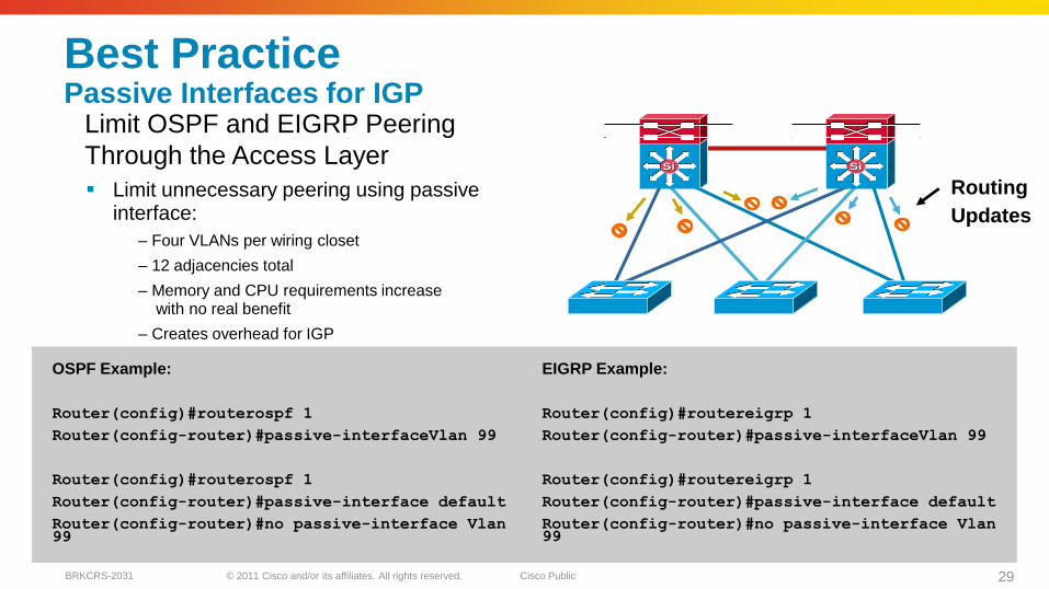
Best PracticePassive Interfaces for IGP
Limit unnecessary peering using passive interface:
– Four VLANs per wiring closet
– 12 adjacencies total
– Memory and CPU requirements increasewith no real benefit
– Creates overhead for IGP
Routing
Updates
OSPF Example:
Router(config)#routerospf 1
Router(config-router)#passive-interfaceVlan 99
Router(config)#routerospf 1
Router(config-router)#passive-interface default
Router(config-router)#no passive-interface Vlan99
EIGRP Example:
Router(config)#routereigrp 1
Router(config-router)#passive-interfaceVlan 99
Router(config)#routereigrp 1
Router(config-router)#passive-interface default
Router(config-router)#no passive-interface Vlan99
Distribution
Access
SiSiSiSi
Limit OSPF and EIGRP Peering
Through the Access Layer
© 2011 Cisco and/or its affiliates. All rights reserved. Cisco PublicBRKCRS-2031 30
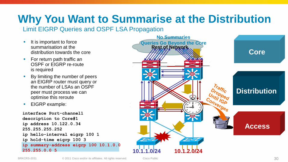
interface Port-channel1
description to Core#1
ip address 10.122.0.34
255.255.255.252
ip hello-interval eigrp 100 1
ip hold-time eigrp 100 3
ip summary-address eigrp 100 10.1.0.0
255.255.0.0 5 10.1.2.0/2410.1.1.0/24
Why You Want to Summarise at the Distribution
It is important to force summarisation at the distribution towards the core
For return path traffic an OSPF or EIGRP re-route is required
By limiting the number of peers an EIGRP router must query or the number of LSAs an OSPF peer must process we can optimise this reroute
EIGRP example:
SiSiSiSi
SiSi SiSi
No Summaries
Queries Go Beyond the CoreRest of Network
Access
Distribution
Core
Limit EIGRP Queries and OSPF LSA Propagation
© 2011 Cisco and/or its affiliates. All rights reserved. Cisco PublicBRKCRS-2031 31
SiSiSiSi
SiSi SiSi
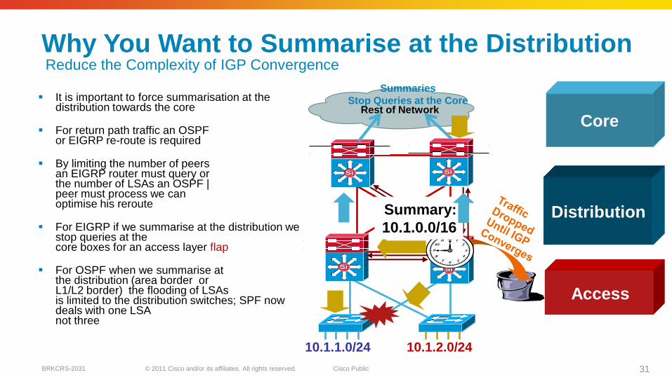
Why You Want to Summarise at the Distribution
It is important to force summarisation at the distribution towards the core
For return path traffic an OSPFor EIGRP re-route is required
By limiting the number of peers an EIGRP router must query or the number of LSAs an OSPF |peer must process we can optimise his reroute
For EIGRP if we summarise at the distribution we stop queries at the core boxes for an access layer flap
For OSPF when we summarise at the distribution (area border or L1/L2 border) the flooding of LSAs is limited to the distribution switches; SPF now deals with one LSA not three
10.1.2.0/2410.1.1.0/24
Rest of Network
Summary:
10.1.0.0/16
Summaries
Stop Queries at the Core
Reduce the Complexity of IGP Convergence
Access
Distribution
Core
© 2011 Cisco and/or its affiliates. All rights reserved. Cisco PublicBRKCRS-2031 32
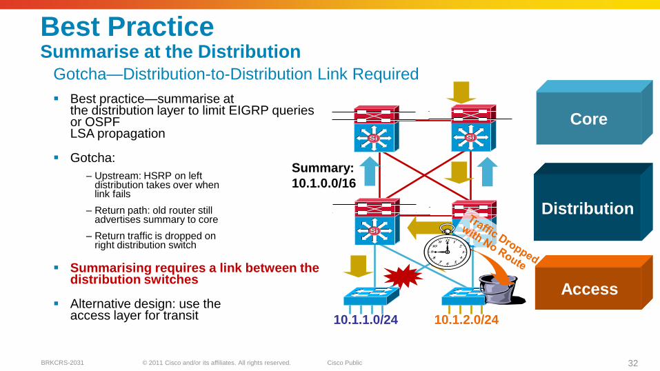
Best Practice Summarise at the Distribution
Best practice—summarise at the distribution layer to limit EIGRP queries or OSPF LSA propagation
Gotcha:
– Upstream: HSRP on leftdistribution takes over whenlink fails
– Return path: old router still advertises summary to core
– Return traffic is dropped on right distribution switch
Summarising requires a link between the distribution switches
Alternative design: use the access layer for transit 10.1.2.0/2410.1.1.0/24
Summary:
10.1.0.0/16
SiSiSiSi
SiSi SiSi
Gotcha—Distribution-to-Distribution Link Required
Access
Distribution
Core
© 2011 Cisco and/or its affiliates. All rights reserved. Cisco PublicBRKCRS-2031 33
SiSi
Load-Sharing
Simple
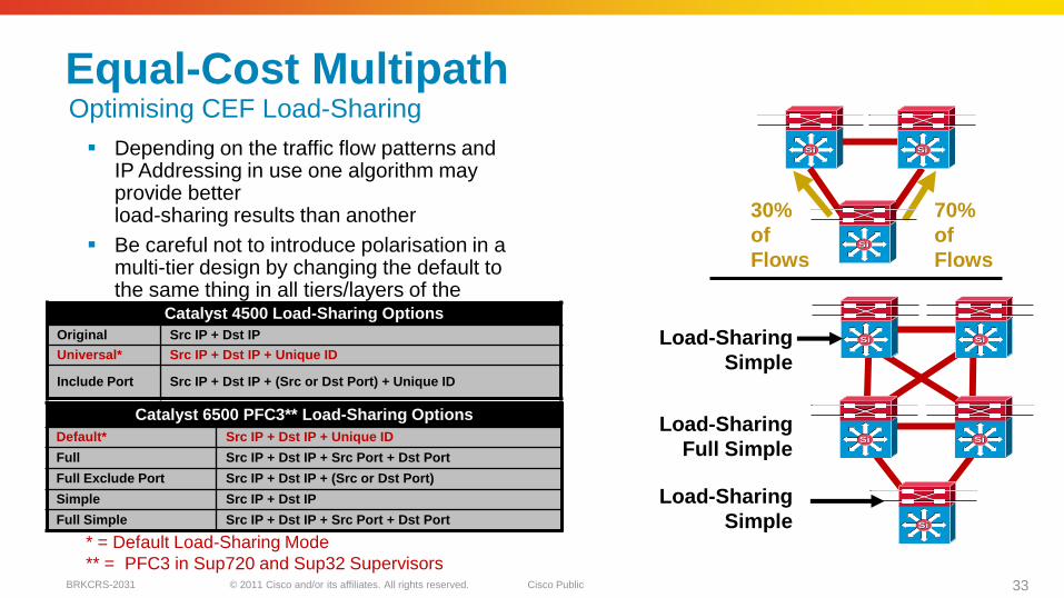
Equal-Cost Multipath
Depending on the traffic flow patterns and IP Addressing in use one algorithm may provide better load-sharing results than another
Be careful not to introduce polarisation in a multi-tier design by changing the default to the same thing in all tiers/layers of the network
SiSiSiSi
SiSi
30%
of
Flows
70%
of
Flows
SiSiSiSi
SiSiSiSiLoad-Sharing
Simple
Load-Sharing
Full Simple
* = Default Load-Sharing Mode
** = PFC3 in Sup720 and Sup32 Supervisors
Catalyst 6500 PFC3** Load-Sharing Options
Default* Src IP + Dst IP + Unique ID
Full Src IP + Dst IP + Src Port + Dst Port
Full Exclude Port Src IP + Dst IP + (Src or Dst Port)
Simple Src IP + Dst IP
Full Simple Src IP + Dst IP + Src Port + Dst Port
Catalyst 4500 Load-Sharing Options
Original Src IP + Dst IP
Universal* Src IP + Dst IP + Unique ID
Include Port Src IP + Dst IP + (Src or Dst Port) + Unique ID
Optimising CEF Load-Sharing
© 2011 Cisco and/or its affiliates. All rights reserved. Cisco PublicBRKCRS-2031 34
SiSiSiSi
SiSi SiSi
SiSi SiSi
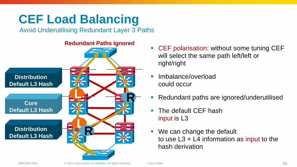
CEF Load Balancing
CEF polarisation: without some tuning CEF will select the same path left/left or right/right
Imbalance/overloadcould occur
Redundant paths are ignored/underutilised
The default CEF hash input is L3
We can change the default to use L3 + L4 information as input to the hash derivation
L
L
R
R
Redundant Paths Ignored
Distribution
Default L3 Hash
Core
Default L3 Hash
Distribution
Default L3 Hash
Avoid Underutilising Redundant Layer 3 Paths
© 2011 Cisco and/or its affiliates. All rights reserved. Cisco PublicBRKCRS-2031 35
SiSiSiSi
SiSi SiSi
SiSi SiSi
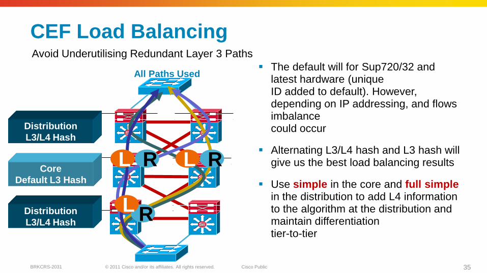
CEF Load Balancing
The default will for Sup720/32 and latest hardware (unique ID added to default). However, depending on IP addressing, and flows imbalance could occur
Alternating L3/L4 hash and L3 hash will give us the best load balancing results
Use simple in the core and full simplein the distribution to add L4 information to the algorithm at the distribution and maintain differentiation tier-to-tier
RL
RL
RL
All Paths Used
Distribution
L3/L4 Hash
Core
Default L3 Hash
Distribution
L3/L4 Hash
Avoid Underutilising Redundant Layer 3 Paths
© 2011 Cisco and/or its affiliates. All rights reserved. Cisco PublicBRKCRS-2031 36
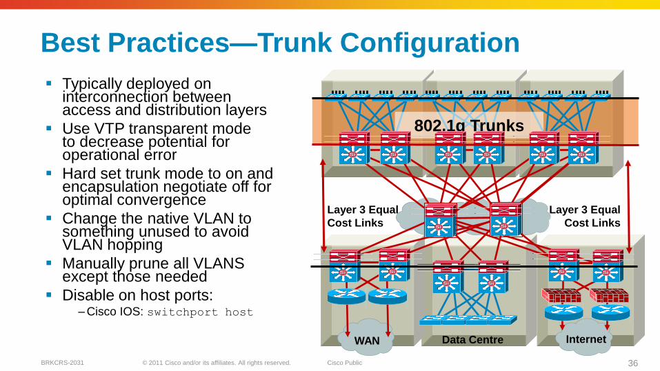
Best Practices—Trunk Configuration
Typically deployed on interconnection between access and distribution layers
Use VTP transparent mode to decrease potential for operational error
Hard set trunk mode to on and encapsulation negotiate off for optimal convergence
Change the native VLAN to something unused to avoid VLAN hopping
Manually prune all VLANS except those needed
Disable on host ports:– Cisco IOS: switchport host
Data CentreWAN Internet
Layer 3 Equal
Cost Links
Layer 3 Equal
Cost Links
802.1q Trunks
SiSi SiSi SiSi SiSi SiSi SiSi
SiSiSiSi
SiSiSiSi
SiSi SiSiSiSiSiSi
© 2011 Cisco and/or its affiliates. All rights reserved. Cisco PublicBRKCRS-2031 37
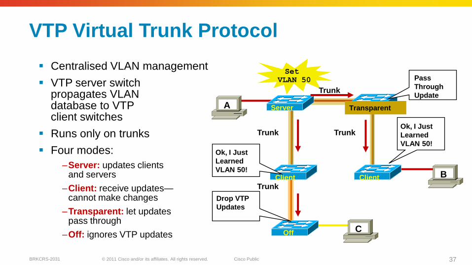
VTP Virtual Trunk Protocol
Centralised VLAN management
VTP server switch propagates VLAN database to VTPclient switches
Runs only on trunks
Four modes:
–Server: updates clientsand servers
–Client: receive updates—cannot make changes
–Transparent: let updates pass through
–Off: ignores VTP updates
FServer
Set
VLAN 50
Trunk
Trunk Trunk
Client
Off
Trunk
A
B
C
Client
Transparent
Ok, I Just
Learned
VLAN 50!
Drop VTP
Updates
Pass
Through
Update
Ok, I Just
Learned
VLAN 50!
© 2011 Cisco and/or its affiliates. All rights reserved. Cisco PublicBRKCRS-2031 38
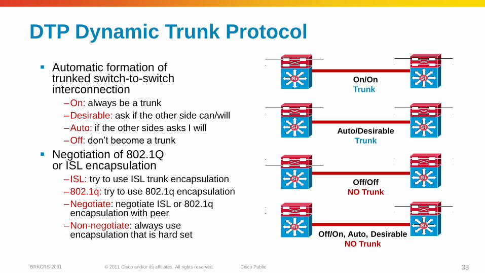
DTP Dynamic Trunk Protocol
Automatic formation of trunked switch-to-switch interconnection
–On: always be a trunk
–Desirable: ask if the other side can/will
–Auto: if the other sides asks I will
–Off: don’t become a trunk
Negotiation of 802.1Qor ISL encapsulation
– ISL: try to use ISL trunk encapsulation
–802.1q: try to use 802.1q encapsulation
–Negotiate: negotiate ISL or 802.1qencapsulation with peer
–Non-negotiate: always use encapsulation that is hard set
On/On
Trunk
Auto/Desirable
Trunk
Off/Off
NO Trunk
Off/On, Auto, Desirable
NO Trunk
SiSi SiSi
SiSi SiSi
SiSi SiSi
SiSiSiSi
© 2011 Cisco and/or its affiliates. All rights reserved. Cisco PublicBRKCRS-2031 39
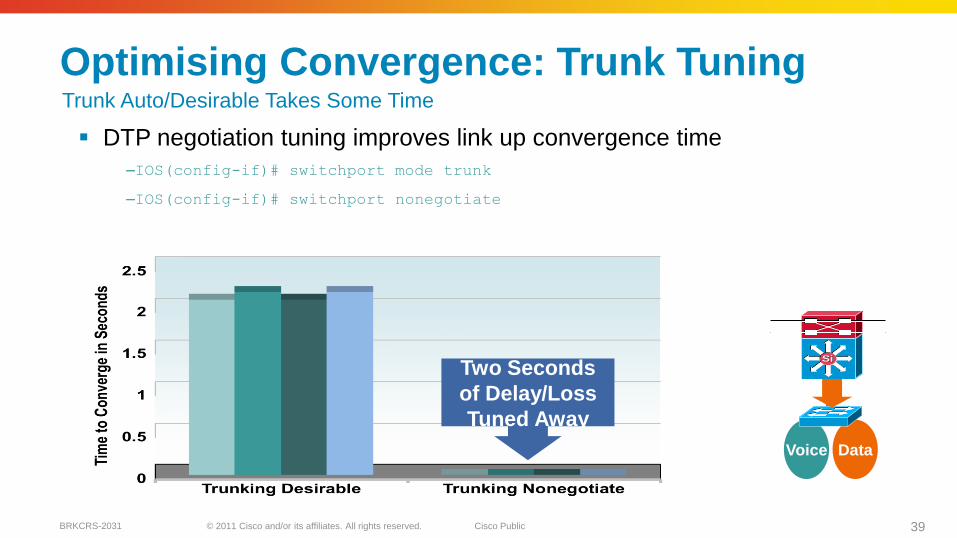
Optimising Convergence: Trunk Tuning
DTP negotiation tuning improves link up convergence time
–IOS(config-if)# switchport mode trunk
–IOS(config-if)# switchport nonegotiate
Voice Data
Two Seconds
of Delay/Loss
Tuned Away
SiSi
Trunk Auto/Desirable Takes Some Time
© 2011 Cisco and/or its affiliates. All rights reserved. Cisco PublicBRKCRS-2031 40
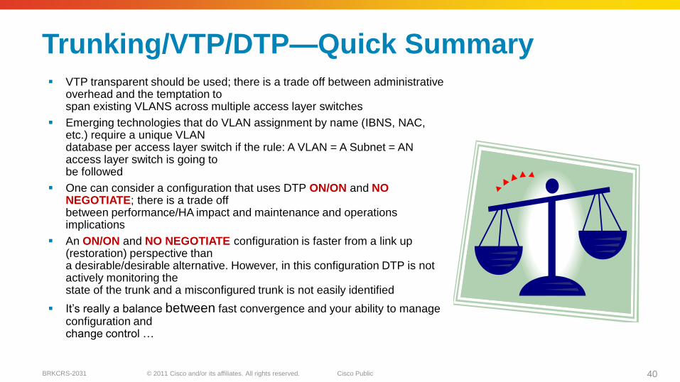
Trunking/VTP/DTP—Quick Summary VTP transparent should be used; there is a trade off between administrative
overhead and the temptation to span existing VLANS across multiple access layer switches
Emerging technologies that do VLAN assignment by name (IBNS, NAC, etc.) require a unique VLAN database per access layer switch if the rule: A VLAN = A Subnet = AN access layer switch is going to be followed
One can consider a configuration that uses DTP ON/ON and NO NEGOTIATE; there is a trade off between performance/HA impact and maintenance and operations implications
An ON/ON and NO NEGOTIATE configuration is faster from a link up (restoration) perspective than a desirable/desirable alternative. However, in this configuration DTP is not actively monitoring the state of the trunk and a misconfigured trunk is not easily identified
It’s really a balance between fast convergence and your ability to manage configuration and change control …
© 2011 Cisco and/or its affiliates. All rights reserved. Cisco PublicBRKCRS-2031 41
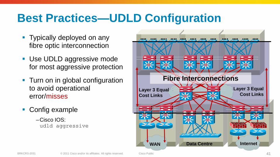
Best Practices—UDLD Configuration
Typically deployed on any fibre optic interconnection
Use UDLD aggressive mode for most aggressive protection
Turn on in global configuration to avoid operational error/misses
Config example
–Cisco IOS:udld aggressive
Data CentreWAN Internet
Layer 3 Equal
Cost LinksLayer 3 Equal
Cost Links
Fibre Interconnections
SiSi SiSi SiSi SiSi SiSi SiSi
SiSiSiSi
SiSiSiSi
SiSi SiSiSiSiSiSi
© 2011 Cisco and/or its affiliates. All rights reserved. Cisco PublicBRKCRS-2031 42
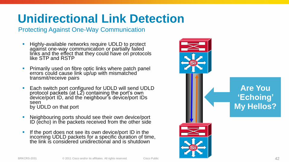
Unidirectional Link Detection
Highly-available networks require UDLD to protect against one-way communication or partially failed links and the effect that they could have on protocols like STP and RSTP
Primarily used on fibre optic links where patch panel errors could cause link up/up with mismatched transmit/receive pairs
Each switch port configured for UDLD will send UDLD protocol packets (at L2) containing the port’s own device/port ID, and the neighbour’s device/port IDs seen by UDLD on that port
Neighbouring ports should see their own device/port ID (echo) in the packets received from the other side
If the port does not see its own device/port ID in the incoming UDLD packets for a specific duration of time, the link is considered unidirectional and is shutdown
Are You ‗Echoing‘
My Hellos?
SiSi
SiSi
Protecting Against One-Way Communication
© 2011 Cisco and/or its affiliates. All rights reserved. Cisco PublicBRKCRS-2031 43
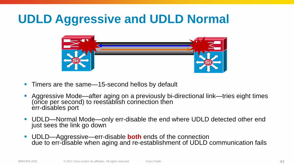
UDLD Aggressive and UDLD Normal
Timers are the same—15-second hellos by default
Aggressive Mode—after aging on a previously bi-directional link—tries eight times (once per second) to reestablish connection then err-disables port
UDLD—Normal Mode—only err-disable the end where UDLD detected other end just sees the link go down
UDLD—Aggressive—err-disable both ends of the connection due to err-disable when aging and re-establishment of UDLD communication fails
SiSi SiSi
© 2011 Cisco and/or its affiliates. All rights reserved. Cisco PublicBRKCRS-2031 44
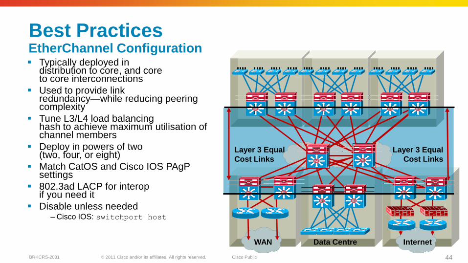
Best PracticesEtherChannel Configuration Typically deployed in
distribution to core, and core to core interconnections
Used to provide link redundancy—while reducing peering complexity
Tune L3/L4 load balancing hash to achieve maximum utilisation of channel members
Deploy in powers of two (two, four, or eight)
Match CatOS and Cisco IOS PAgPsettings
802.3ad LACP for interopif you need it
Disable unless needed– Cisco IOS: switchport host
Data CentreWAN Internet
Layer 3 Equal
Cost Links
Layer 3 Equal
Cost Links
SiSi SiSi SiSi SiSi SiSi SiSi
SiSiSiSi
SiSiSiSi
SiSi SiSiSiSiSiSi
© 2011 Cisco and/or its affiliates. All rights reserved. Cisco PublicBRKCRS-2031 45
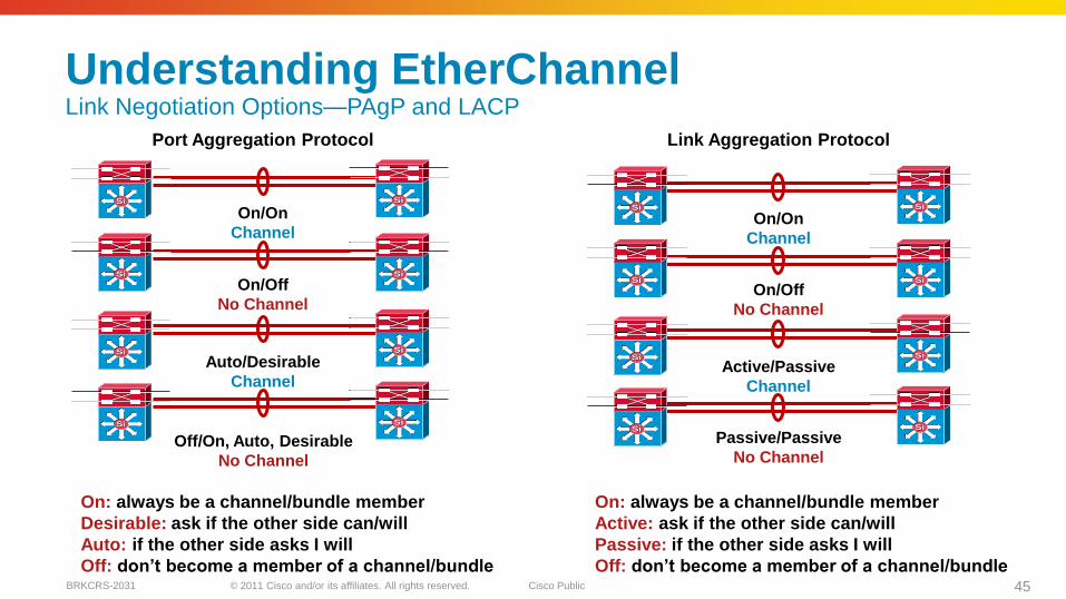
Understanding EtherChannelLink Negotiation Options—PAgP and LACP
On/On
Channel
On/Off
No Channel
Auto/Desirable
Channel
Off/On, Auto, Desirable
No Channel
SiSi SiSi
SiSi SiSi
SiSi SiSi
SiSiSiSi
On/On
Channel
On/Off
No Channel
Active/Passive
Channel
Passive/Passive
No Channel
SiSi
SiSi SiSi
SiSi SiSi
SiSiSiSi
SiSi
Port Aggregation Protocol Link Aggregation Protocol
On: always be a channel/bundle member
Active: ask if the other side can/will
Passive: if the other side asks I will
Off: don‘t become a member of a channel/bundle
On: always be a channel/bundle member
Desirable: ask if the other side can/will
Auto: if the other side asks I will
Off: don‘t become a member of a channel/bundle
© 2011 Cisco and/or its affiliates. All rights reserved. Cisco PublicBRKCRS-2031 46
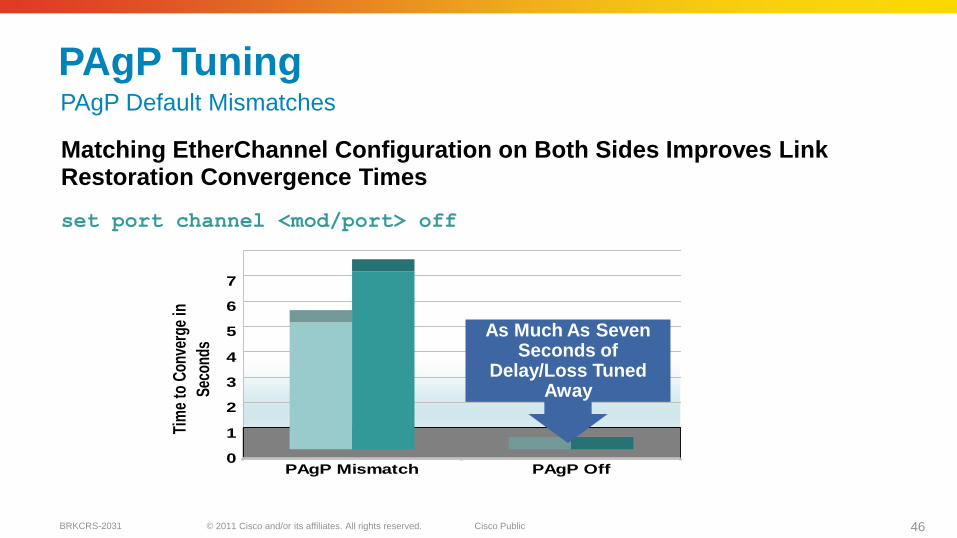
PAgP Tuning
Matching EtherChannel Configuration on Both Sides Improves Link Restoration Convergence Times
set port channel <mod/port> off
0
1
2
3
4
5
6
7
Tim
e to
Con
verg
e in
Sec
onds
PAgP Mismatch PAgP Off
As Much As Seven Seconds of
Delay/Loss Tuned Away
PAgP Default Mismatches
© 2011 Cisco and/or its affiliates. All rights reserved. Cisco PublicBRKCRS-2031 47
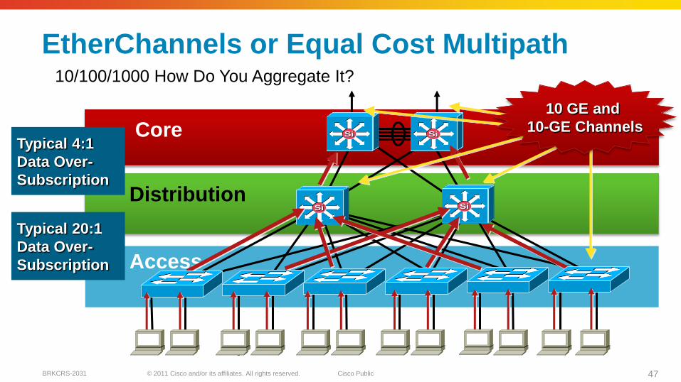
EtherChannels or Equal Cost Multipath
SiSi SiSi
SiSiSiSi
Access
Distribution
Core10 GE and
10-GE Channels
Typical 20:1
Data Over-
Subscription
Typical 4:1
Data Over-
Subscription
10/100/1000 How Do You Aggregate It?
© 2011 Cisco and/or its affiliates. All rights reserved. Cisco PublicBRKCRS-2031 48
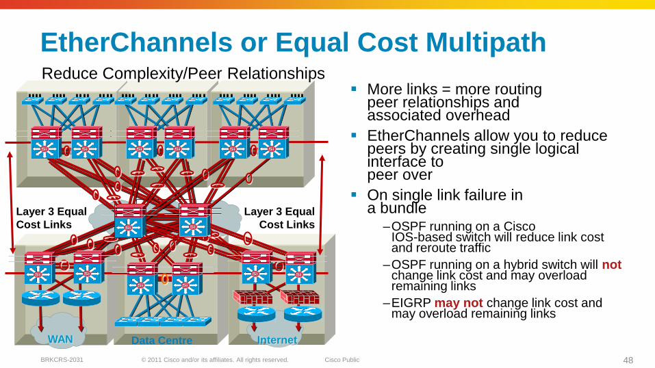
EtherChannels or Equal Cost Multipath
More links = more routing peer relationships and associated overhead
EtherChannels allow you to reduce peers by creating single logical interface to peer over
On single link failure in a bundle
–OSPF running on a Cisco IOS-based switch will reduce link cost and reroute traffic
–OSPF running on a hybrid switch will notchange link cost and may overload remaining links
–EIGRP may not change link cost and may overload remaining links
Data CentreWAN Internet
Layer 3 Equal
Cost Links
Layer 3 Equal
Cost Links SiSiSiSi
SiSi SiSi SiSi SiSi SiSi SiSi
SiSiSiSi
SiSi SiSiSiSiSiSi
Reduce Complexity/Peer Relationships
© 2011 Cisco and/or its affiliates. All rights reserved. Cisco PublicBRKCRS-2031 49
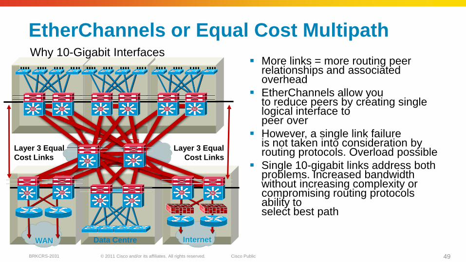
EtherChannels or Equal Cost Multipath
More links = more routing peer relationships and associated overhead
EtherChannels allow you to reduce peers by creating single logical interface to peer over
However, a single link failure is not taken into consideration by routing protocols. Overload possible
Single 10-gigabit links address both problems. Increased bandwidth without increasing complexity or compromising routing protocols ability to select best path
Data CentreWAN Internet
Layer 3 Equal
Cost Links
Layer 3 Equal
Cost LinksSiSiSiSi
SiSiSiSi
SiSi SiSiSiSiSiSi
SiSi SiSi SiSi SiSi SiSi SiSi
Why 10-Gigabit Interfaces
© 2011 Cisco and/or its affiliates. All rights reserved. Cisco PublicBRKCRS-2031 50
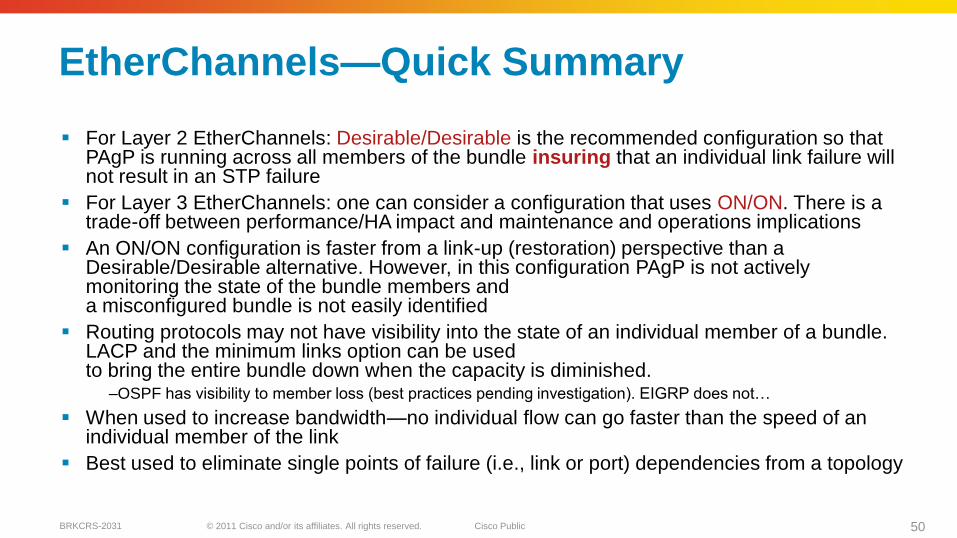
EtherChannels—Quick Summary
For Layer 2 EtherChannels: Desirable/Desirable is the recommended configuration so that PAgP is running across all members of the bundle insuring that an individual link failure will not result in an STP failure
For Layer 3 EtherChannels: one can consider a configuration that uses ON/ON. There is a trade-off between performance/HA impact and maintenance and operations implications
An ON/ON configuration is faster from a link-up (restoration) perspective than a Desirable/Desirable alternative. However, in this configuration PAgP is not actively monitoring the state of the bundle members and a misconfigured bundle is not easily identified
Routing protocols may not have visibility into the state of an individual member of a bundle. LACP and the minimum links option can be used to bring the entire bundle down when the capacity is diminished.
–OSPF has visibility to member loss (best practices pending investigation). EIGRP does not…
When used to increase bandwidth—no individual flow can go faster than the speed of an individual member of the link
Best used to eliminate single points of failure (i.e., link or port) dependencies from a topology
© 2011 Cisco and/or its affiliates. All rights reserved. Cisco PublicBRKCRS-2031 51
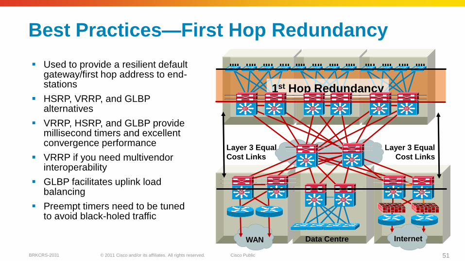
Best Practices—First Hop Redundancy
Used to provide a resilient default gateway/first hop address to end-stations
HSRP, VRRP, and GLBPalternatives
VRRP, HSRP, and GLBP provide millisecond timers and excellent convergence performance
VRRP if you need multivendor interoperability
GLBP facilitates uplink load balancing
Preempt timers need to be tuned to avoid black-holed traffic
Data CentreWAN Internet
Layer 3 Equal
Cost Links
Layer 3 Equal
Cost Links
1st Hop Redundancy
SiSi SiSi SiSi SiSi SiSi SiSi
SiSiSiSi
SiSiSiSi
SiSi SiSiSiSiSiSi
© 2011 Cisco and/or its affiliates. All rights reserved. Cisco PublicBRKCRS-2031 52
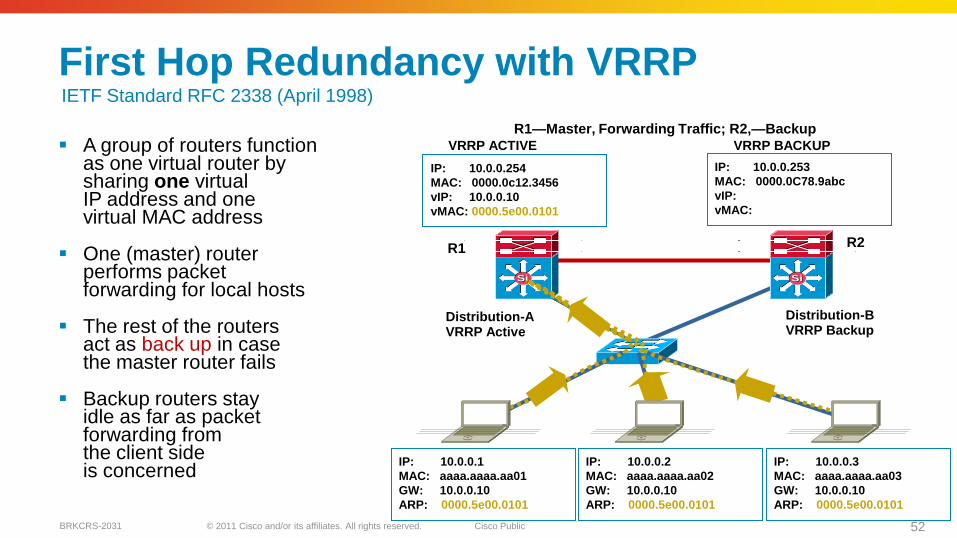
First Hop Redundancy with VRRP
A group of routers function as one virtual router by sharing one virtual IP address and one virtual MAC address
One (master) router performs packet forwarding for local hosts
The rest of the routers act as back up in case the master router fails
Backup routers stay idle as far as packet forwarding from the client side is concerned
R1—Master, Forwarding Traffic; R2,—Backup
VRRP ACTIVE VRRP BACKUP
IP: 10.0.0.254
MAC: 0000.0c12.3456
vIP: 10.0.0.10
vMAC: 0000.5e00.0101
IP: 10.0.0.253
MAC: 0000.0C78.9abc
vIP:
vMAC:
IP: 10.0.0.1
MAC: aaaa.aaaa.aa01
GW: 10.0.0.10
ARP: 0000.5e00.0101
IP: 10.0.0.2
MAC: aaaa.aaaa.aa02
GW: 10.0.0.10
ARP: 0000.5e00.0101
IP: 10.0.0.3
MAC: aaaa.aaaa.aa03
GW: 10.0.0.10
ARP: 0000.5e00.0101
SiSiSiSi
Access-a
Distribution-AVRRP Active
Distribution-BVRRP Backup
R1 R2
IETF Standard RFC 2338 (April 1998)
© 2011 Cisco and/or its affiliates. All rights reserved. Cisco PublicBRKCRS-2031 53
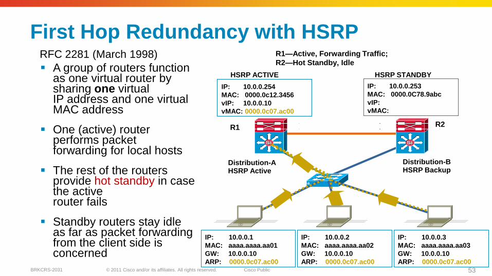
First Hop Redundancy with HSRP
A group of routers function as one virtual router by sharing one virtual IP address and one virtual MAC address
One (active) router performs packet forwarding for local hosts
The rest of the routers provide hot standby in case the active router fails
Standby routers stay idle as far as packet forwarding from the client side is concerned
IP: 10.0.0.1
MAC: aaaa.aaaa.aa01
GW: 10.0.0.10
ARP: 0000.0c07.ac00
SiSiSiSi
Access-a
R1
HSRP ACTIVE HSRP STANDBY
IP: 10.0.0.254
MAC: 0000.0c12.3456
vIP: 10.0.0.10
vMAC: 0000.0c07.ac00
IP: 10.0.0.253
MAC: 0000.0C78.9abc
vIP:
vMAC:
IP: 10.0.0.2
MAC: aaaa.aaaa.aa02
GW: 10.0.0.10
ARP: 0000.0c07.ac00
IP: 10.0.0.3
MAC: aaaa.aaaa.aa03
GW: 10.0.0.10
ARP: 0000.0c07.ac00
R1—Active, Forwarding Traffic;
R2—Hot Standby, Idle
R2
RFC 2281 (March 1998)
Distribution-AHSRP Active
Distribution-BHSRP Backup
© 2011 Cisco and/or its affiliates. All rights reserved. Cisco PublicBRKCRS-2031 54
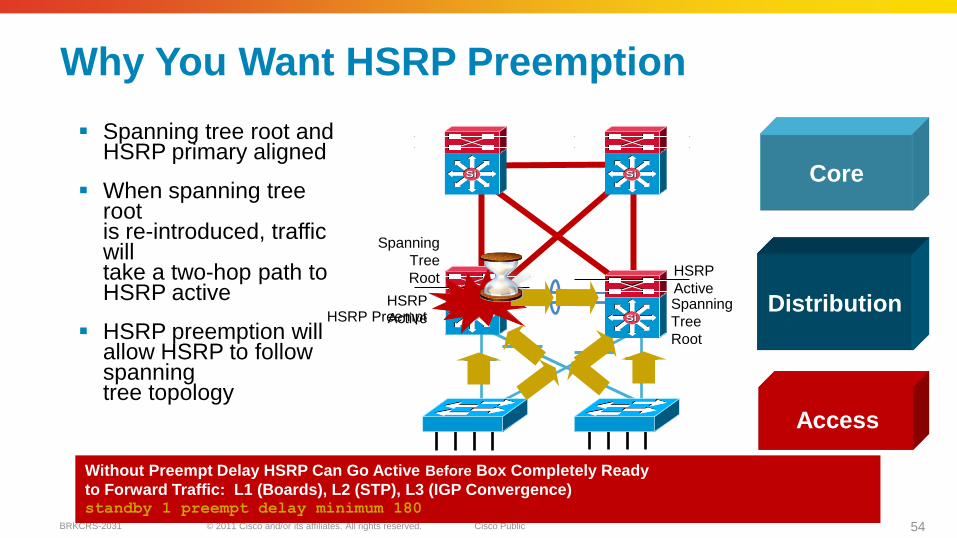
Spanning tree root and HSRP primary aligned
When spanning tree root is re-introduced, traffic will take a two-hop path to HSRP active
HSRP preemption will allow HSRP to follow spanning tree topology
Why You Want HSRP Preemption
SiSiSiSi
SiSiSiSi
Access
Distribution
Core
Spanning
Tree
RootHSRP
ActiveHSRP
ActiveSpanning
Tree
Root
HSRP Preempt
Without Preempt Delay HSRP Can Go Active Before Box Completely Ready
to Forward Traffic: L1 (Boards), L2 (STP), L3 (IGP Convergence)standby 1 preempt delay minimum 180
© 2011 Cisco and/or its affiliates. All rights reserved. Cisco PublicBRKCRS-2031 55
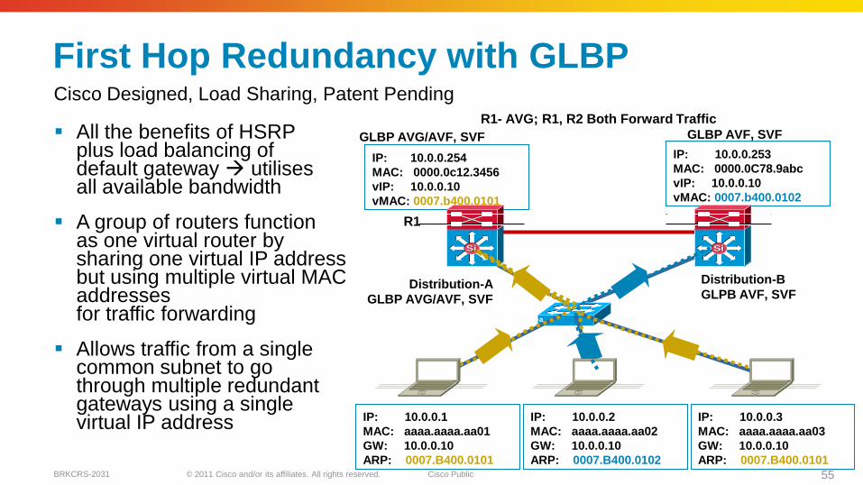
First Hop Redundancy with GLBP
All the benefits of HSRP plus load balancing of default gateway utilisesall available bandwidth
A group of routers function as one virtual router by sharing one virtual IP address but using multiple virtual MAC addresses for traffic forwarding
Allows traffic from a single common subnet to go through multiple redundant gateways using a single virtual IP address
GLBP AVG/AVF, SVF GLBP AVF, SVF
R1- AVG; R1, R2 Both Forward Traffic
IP: 10.0.0.254
MAC: 0000.0c12.3456
vIP: 10.0.0.10
vMAC: 0007.b400.0101
IP: 10.0.0.253
MAC: 0000.0C78.9abc
vIP: 10.0.0.10
vMAC: 0007.b400.0102
IP: 10.0.0.1
MAC: aaaa.aaaa.aa01
GW: 10.0.0.10
ARP: 0007.B400.0101
IP: 10.0.0.2
MAC: aaaa.aaaa.aa02
GW: 10.0.0.10
ARP: 0007.B400.0102
IP: 10.0.0.3
MAC: aaaa.aaaa.aa03
GW: 10.0.0.10
ARP: 0007.B400.0101
SiSiSiSi
Access-a
Distribution-A
GLBP AVG/AVF, SVF
Distribution-B
GLPB AVF, SVF
R1
Cisco Designed, Load Sharing, Patent Pending
© 2011 Cisco and/or its affiliates. All rights reserved. Cisco PublicBRKCRS-2031 56
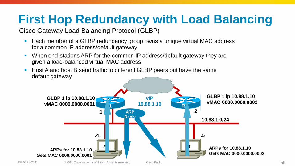
First Hop Redundancy with Load Balancing
Each member of a GLBP redundancy group owns a unique virtual MAC address for a common IP address/default gateway
When end-stations ARP for the common IP address/default gateway they are given a load-balanced virtual MAC address
Host A and host B send traffic to different GLBP peers but have the same default gateway
10.88.1.0/24
.5.4
.1 .2
vIP
10.88.1.10
GLBP 1 ip 10.88.1.10
vMAC 0000.0000.0001
GLBP 1 ip 10.88.1.10
vMAC 0000.0000.0002
ARPs for 10.88.1.10
Gets MAC 0000.0000.0001
ARPs for 10.88.1.10
Gets MAC 0000.0000.0002
A B
R1 R2
ARP
Reply
Cisco Gateway Load Balancing Protocol (GLBP)
© 2011 Cisco and/or its affiliates. All rights reserved. Cisco PublicBRKCRS-2031 57
SiSiSiSi
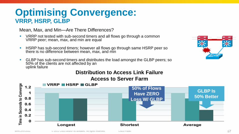
Optimising Convergence: VRRP, HSRP, GLBP
VRRP not tested with sub-second timers and all flows go through a common VRRP peer; mean, max, and min are equal
HSRP has sub-second timers; however all flows go through same HSRP peer so there is no difference between mean, max, and min
GLBP has sub-second timers and distributes the load amongst the GLBP peers; so 50% of the clients are not affected by anuplink failure
Distribution to Access Link Failure
Access to Server Farm
50% of Flows
Have ZERO
Loss W/ GLBP
GLBP Is
50% Better
Mean, Max, and Min—Are There Differences?
© 2011 Cisco and/or its affiliates. All rights reserved. Cisco PublicBRKCRS-2031 58
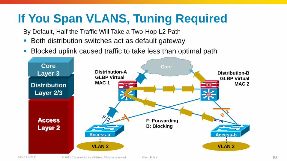
If You Span VLANS, Tuning Required
Both distribution switches act as default gateway
Blocked uplink caused traffic to take less than optimal path
VLAN 2VLAN 2
F: ForwardingB: Blocking
Access-b
SiSiSiSi
Core
Access-a
Distribution-AGLBP Virtual MAC 1
Distribution-BGLBP Virtual
MAC 2
Access
Layer 2
Distribution
Layer 2/3
Core
Layer 3
By Default, Half the Traffic Will Take a Two-Hop L2 Path
© 2011 Cisco and/or its affiliates. All rights reserved. Cisco PublicBRKCRS-2031 59
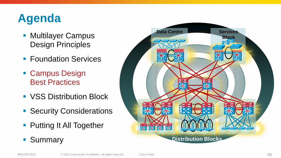
Agenda
Multilayer Campus Design Principles
Foundation Services
Campus Design Best Practices
VSS Distribution Block
Security Considerations
Putting It All Together
Summary
SiSiSiSi
SiSiSiSi
SiSi
Data Centre
SiSi SiSi
Services
Block
Distribution Blocks
SiSi SiSi SiSi
© 2011 Cisco and/or its affiliates. All rights reserved. Cisco PublicBRKCRS-2031 60
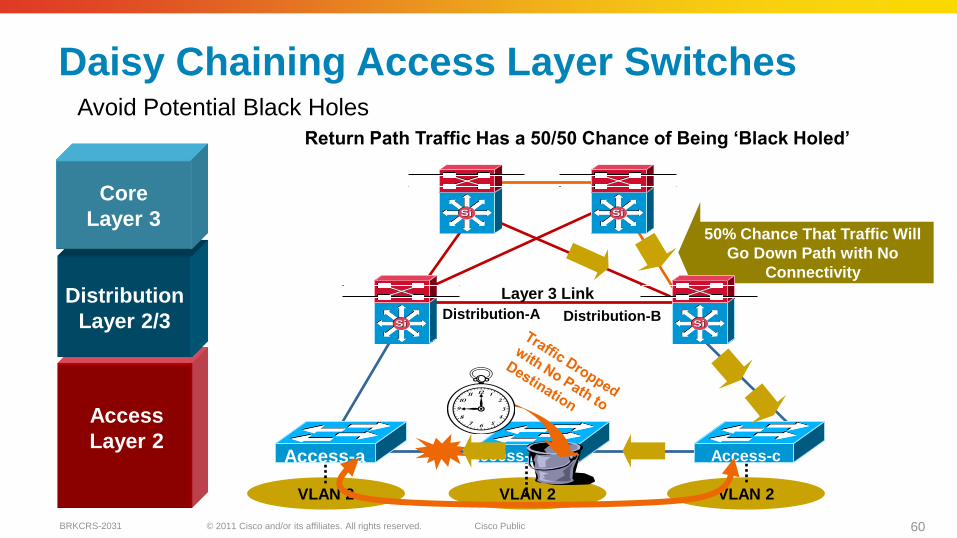
VLAN 2 VLAN 2 VLAN 2
Distribution-A Distribution-B
Access-cAccess-a
Layer 3 Link
Access-n
50% Chance That Traffic Will
Go Down Path with No
Connectivity
Daisy Chaining Access Layer Switches
Return Path Traffic Has a 50/50 Chance of Being ‗Black Holed‘
SiSiSiSi
SiSiSiSi
Access
Layer 2
Distribution
Layer 2/3
Core
Layer 3
Avoid Potential Black Holes
© 2011 Cisco and/or its affiliates. All rights reserved. Cisco PublicBRKCRS-2031 61
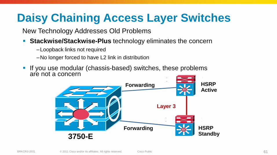
Daisy Chaining Access Layer Switches
Stackwise/Stackwise-Plus technology eliminates the concern
–Loopback links not required
–No longer forced to have L2 link in distribution
If you use modular (chassis-based) switches, these problems are not a concern
HSRP Active
HSRP Standby
Forwarding
Forwarding
3750-E
SiSi
SiSi
Layer 3
New Technology Addresses Old Problems
© 2011 Cisco and/or its affiliates. All rights reserved. Cisco PublicBRKCRS-2031 62
VLAN 2VLAN 2
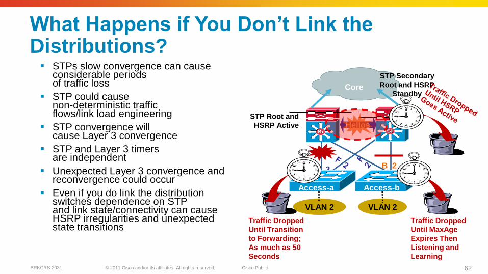
What Happens if You Don‘t Link the Distributions? STPs slow convergence can cause
considerable periods of traffic loss
STP could cause non-deterministic traffic flows/link load engineering
STP convergence will cause Layer 3 convergence
STP and Layer 3 timers are independent
Unexpected Layer 3 convergence and reconvergence could occur
Even if you do link the distribution switches dependence on STPand link state/connectivity can cause HSRP irregularities and unexpected state transitions
B 2
STP Secondary
Root and HSRP
Standby
F 2
Access-b
SiSiSiSi
Core
Hellos
Access-a
STP Root and
HSRP Active
Traffic Dropped
Until MaxAge
Expires Then
Listening and
Learning
Traffic Dropped
Until Transition
to Forwarding;
As much as 50
Seconds
© 2011 Cisco and/or its affiliates. All rights reserved. Cisco PublicBRKCRS-2031 63
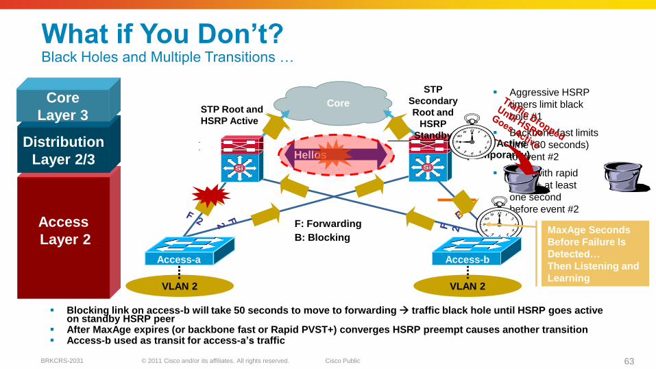
Aggressive HSRP
timers limit black
hole #1
Backbone fast limits
time (30 seconds)
to event #2
Even with rapid
PVST+ at least
one second
before event #2
VLAN 2VLAN 2
What if You Don‘t? Black Holes and Multiple Transitions …
Blocking link on access-b will take 50 seconds to move to forwarding traffic black hole until HSRP goes active on standby HSRP peer
After MaxAge expires (or backbone fast or Rapid PVST+) converges HSRP preempt causes another transition Access-b used as transit for access-a‘s traffic
HSRP Active (Temporarily)
MaxAge Seconds
Before Failure Is
Detected…
Then Listening and
Learning
F: Forwarding
B: Blocking
Access-b
SiSiSiSi
Hellos
Access
Layer 2
Distribution
Layer 2/3
Core
Layer 3Core
STP Root and
HSRP Active
STP
Secondary
Root and
HSRP
Standby
Access-a
© 2011 Cisco and/or its affiliates. All rights reserved. Cisco PublicBRKCRS-2031 64
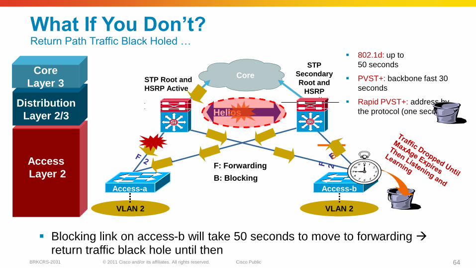
802.1d: up to
50 seconds
PVST+: backbone fast 30
seconds
Rapid PVST+: address by
the protocol (one second)
VLAN 2VLAN 2
What If You Don‘t?Return Path Traffic Black Holed …
Blocking link on access-b will take 50 seconds to move to forwarding return traffic black hole until then
F: Forwarding
B: Blocking
Core
Hellos
STP Root and
HSRP Active
Access-b
STP
Secondary
Root and
HSRP
Standby
SiSiSiSi
Access
Layer 2
Distribution
Layer 2/3
Core
Layer 3
Access-a
© 2011 Cisco and/or its affiliates. All rights reserved. Cisco PublicBRKCRS-2031 65
VLAN 2VLAN 2
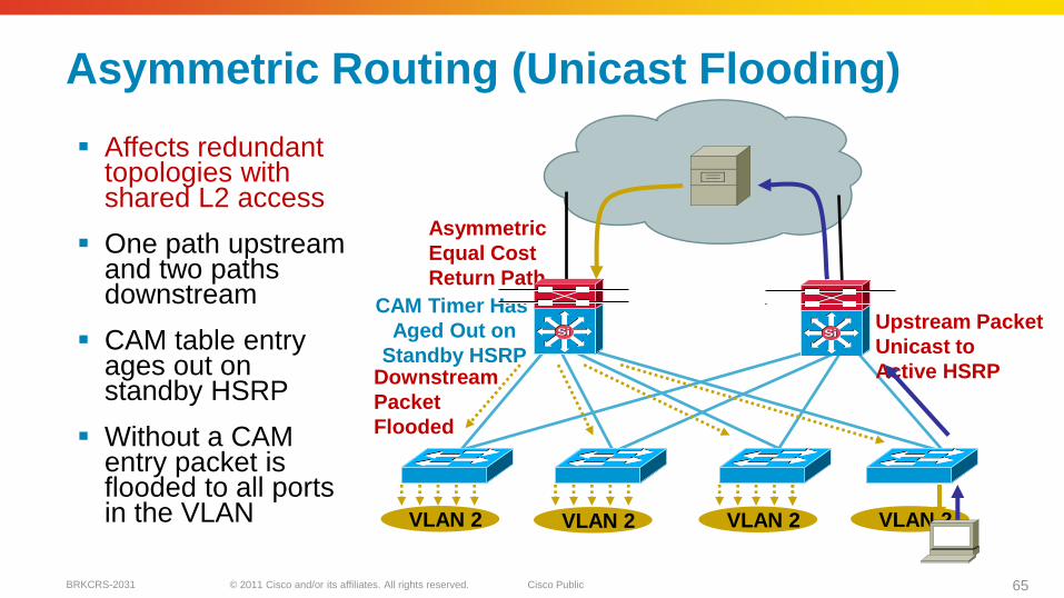
Asymmetric Routing (Unicast Flooding)
Affects redundant topologies with shared L2 access
One path upstream and two paths downstream
CAM table entry ages out on standby HSRP
Without a CAM entry packet is flooded to all ports in the VLAN
Downstream
Packet
Flooded
Upstream Packet
Unicast to
Active HSRP
Asymmetric
Equal Cost
Return Path
CAM Timer Has
Aged Out on
Standby HSRP
VLAN 2 VLAN 2
SiSi SiSi
© 2011 Cisco and/or its affiliates. All rights reserved. Cisco PublicBRKCRS-2031 66
VLAN 2
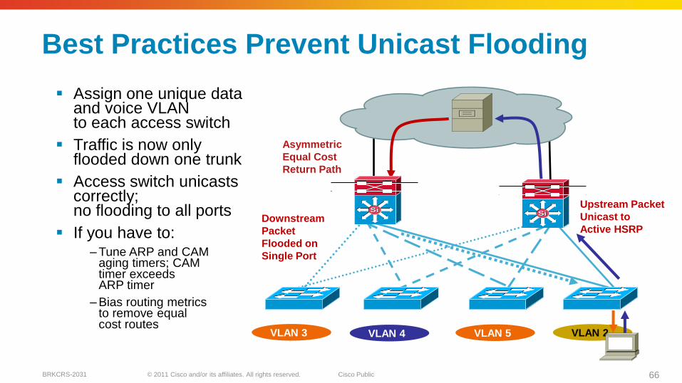
Best Practices Prevent Unicast Flooding
Assign one unique data and voice VLAN to each access switch
Traffic is now only flooded down one trunk
Access switch unicastscorrectly;no flooding to all ports
If you have to:– Tune ARP and CAM
aging timers; CAM timer exceeds ARP timer
– Bias routing metrics to remove equal cost routes
Downstream
Packet
Flooded on
Single Port
Upstream Packet
Unicast to
Active HSRP
Asymmetric
Equal Cost
Return Path
VLAN 3 VLAN 4 VLAN 5
SiSiSiSi
© 2011 Cisco and/or its affiliates. All rights reserved. Cisco PublicBRKCRS-2031 67
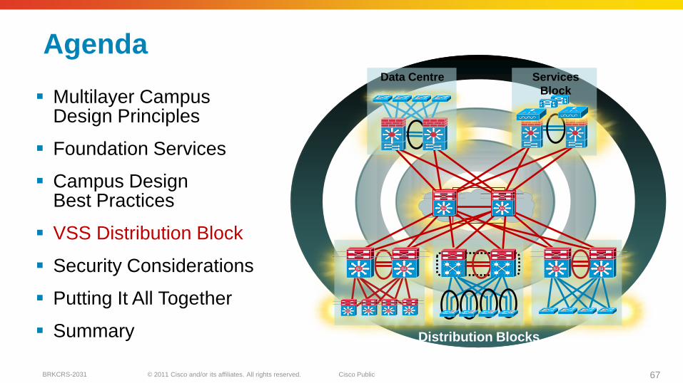
Agenda
Multilayer Campus Design Principles
Foundation Services
Campus Design Best Practices
VSS Distribution Block
Security Considerations
Putting It All Together
Summary
SiSiSiSi
SiSiSiSi
SiSi
Data Centre
SiSi SiSi
Services
Block
Distribution Blocks
SiSi SiSi SiSi
© 2011 Cisco and/or its affiliates. All rights reserved. Cisco PublicBRKCRS-2031 68
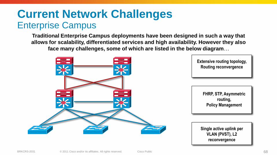
Current Network ChallengesEnterprise Campus
Traditional Enterprise Campus deployments have been designed in such a way that
allows for scalability, differentiated services and high availability. However they also
face many challenges, some of which are listed in the below diagram…
Access
L2/L3
Distribution
L3 Core
FHRP, STP, Asymmetric
routing,
Policy Management
Extensive routing topology,
Routing reconvergence
Single active uplink per
VLAN (PVST), L2
reconvergence
© 2011 Cisco and/or its affiliates. All rights reserved. Cisco PublicBRKCRS-2031 69
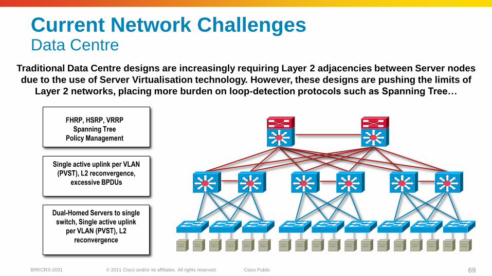
Current Network ChallengesData Centre
Traditional Data Centre designs are increasingly requiring Layer 2 adjacencies between Server nodes
due to the use of Server Virtualisation technology. However, these designs are pushing the limits of
Layer 2 networks, placing more burden on loop-detection protocols such as Spanning Tree…
L2/L3 Core
L2 Access
Dual-Homed Servers to single
switch, Single active uplink
per VLAN (PVST), L2
reconvergence
Single active uplink per VLAN
(PVST), L2 reconvergence,
excessive BPDUs
FHRP, HSRP, VRRP
Spanning Tree
Policy Management
© 2011 Cisco and/or its affiliates. All rights reserved. Cisco PublicBRKCRS-2031 70
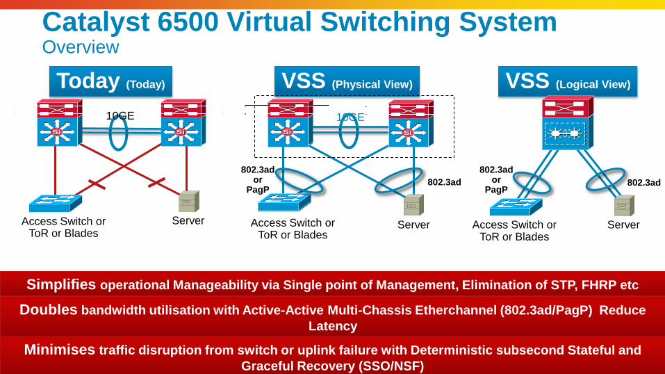
VSS (Physical View)
SiSi
Access Switch orToR or Blades
Server Server Server
10GE 10GE
Access Switch orToR or Blades
Access Switch orToR or Blades
802.3ad
Today (Today) VSS (Logical View)
802.3ador
PagP
802.3ador
PagP802.3ad
Simplifies operational Manageability via Single point of Management, Elimination of STP, FHRP etc
Doubles bandwidth utilisation with Active-Active Multi-Chassis Etherchannel (802.3ad/PagP) Reduce
Latency
Minimises traffic disruption from switch or uplink failure with Deterministic subsecond Stateful and
Graceful Recovery (SSO/NSF)
Catalyst 6500 Virtual Switching SystemOverview
SiSi SiSi SiSiSiSi
© 2011 Cisco and/or its affiliates. All rights reserved. Cisco PublicBRKCRS-2031 71
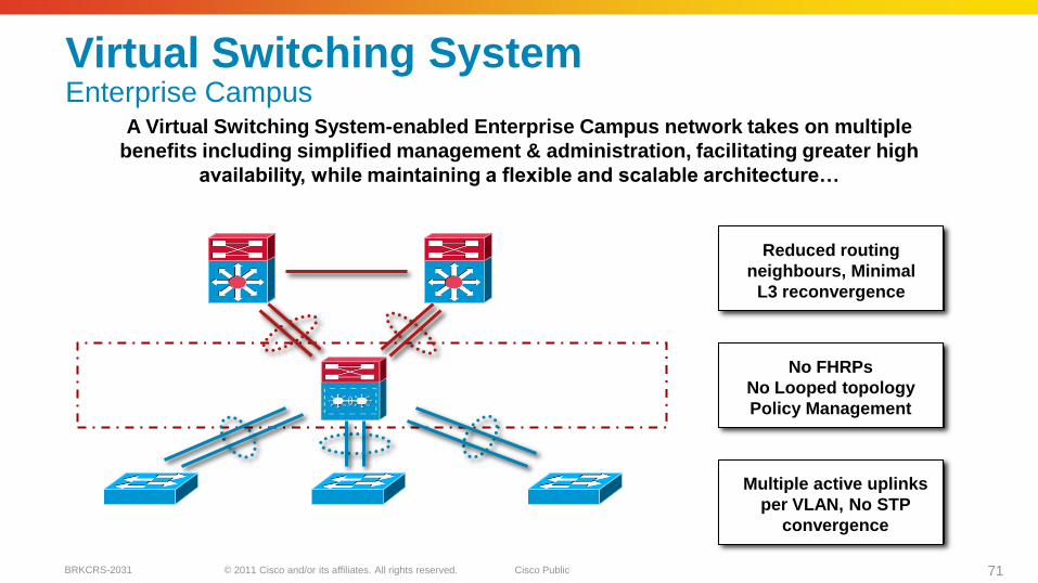
Virtual Switching System Enterprise Campus
A Virtual Switching System-enabled Enterprise Campus network takes on multiple
benefits including simplified management & administration, facilitating greater high
availability, while maintaining a flexible and scalable architecture…
Access
L2/L3
Distribution
L3 Core
No FHRPs
No Looped topology
Policy Management
Reduced routing
neighbours, Minimal
L3 reconvergence
Multiple active uplinks
per VLAN, No STP
convergence
© 2011 Cisco and/or its affiliates. All rights reserved. Cisco PublicBRKCRS-2031 72
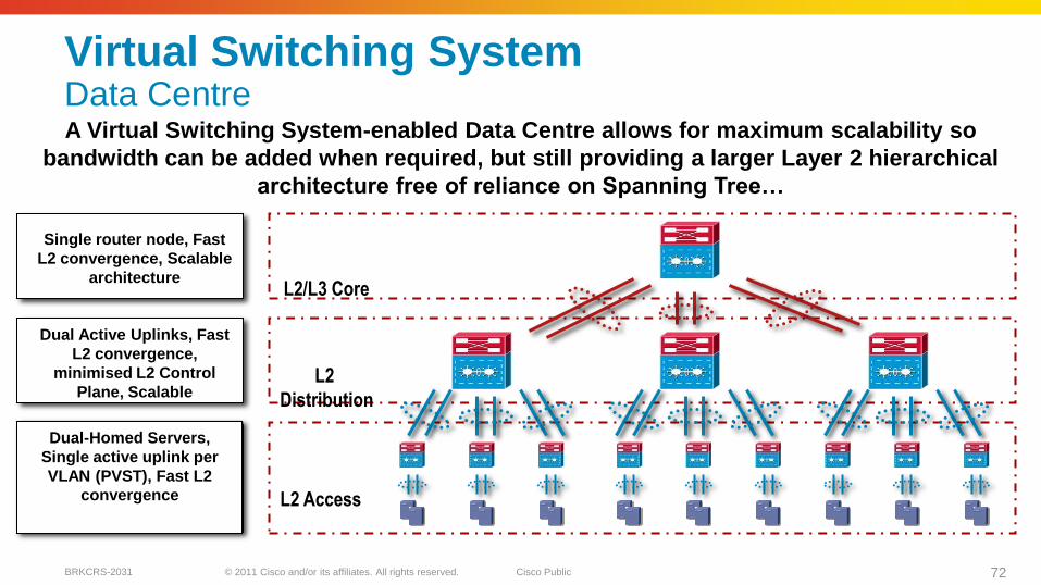
Virtual Switching System Data CentreA Virtual Switching System-enabled Data Centre allows for maximum scalability so
bandwidth can be added when required, but still providing a larger Layer 2 hierarchical
architecture free of reliance on Spanning Tree…
L2/L3 Core
L2
Distribution
L2 Access
Dual-Homed Servers,
Single active uplink per
VLAN (PVST), Fast L2
convergence
Dual Active Uplinks, Fast
L2 convergence,
minimised L2 Control
Plane, Scalable
Single router node, Fast
L2 convergence, Scalable
architecture
© 2011 Cisco and/or its affiliates. All rights reserved. Cisco PublicBRKCRS-2031 73
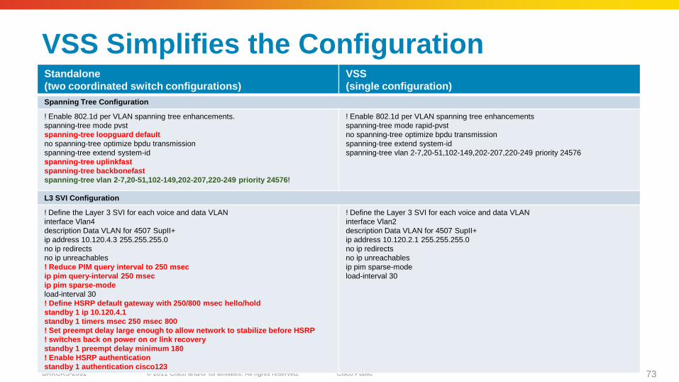
VSS Simplifies the ConfigurationStandalone
(two coordinated switch configurations)
VSS
(single configuration)
Spanning Tree Configuration
! Enable 802.1d per VLAN spanning tree enhancements.
spanning-tree mode pvst
spanning-tree loopguard default
no spanning-tree optimize bpdu transmission
spanning-tree extend system-id
spanning-tree uplinkfast
spanning-tree backbonefast
spanning-tree vlan 2-7,20-51,102-149,202-207,220-249 priority 24576!
! Enable 802.1d per VLAN spanning tree enhancements
spanning-tree mode rapid-pvst
no spanning-tree optimize bpdu transmission
spanning-tree extend system-id
spanning-tree vlan 2-7,20-51,102-149,202-207,220-249 priority 24576
L3 SVI Configuration
! Define the Layer 3 SVI for each voice and data VLAN
interface Vlan4
description Data VLAN for 4507 SupII+
ip address 10.120.4.3 255.255.255.0
no ip redirects
no ip unreachables
! Reduce PIM query interval to 250 msec
ip pim query-interval 250 msec
ip pim sparse-mode
load-interval 30
! Define HSRP default gateway with 250/800 msec hello/hold
standby 1 ip 10.120.4.1
standby 1 timers msec 250 msec 800
! Set preempt delay large enough to allow network to stabilize before HSRP
! switches back on power on or link recovery
standby 1 preempt delay minimum 180
! Enable HSRP authentication
standby 1 authentication cisco123
! Define the Layer 3 SVI for each voice and data VLAN
interface Vlan2
description Data VLAN for 4507 SupII+
ip address 10.120.2.1 255.255.255.0
no ip redirects
no ip unreachables
ip pim sparse-mode
load-interval 30
© 2011 Cisco and/or its affiliates. All rights reserved. Cisco Public 74BRKCRS-2031
VSS Architecture
7474
© 2011 Cisco and/or its affiliates. All rights reserved. Cisco PublicBRKCRS-2031 75
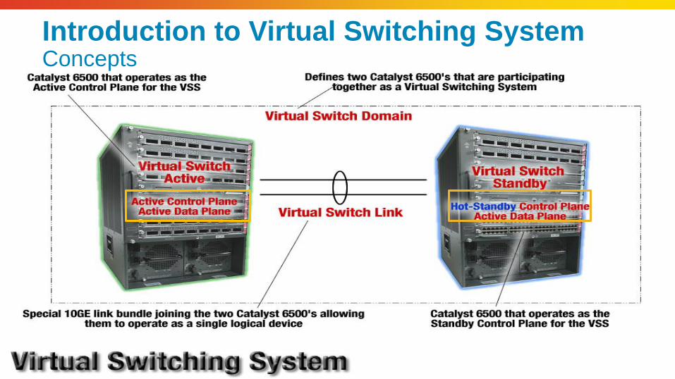
Introduction to Virtual Switching SystemConcepts
© 2011 Cisco and/or its affiliates. All rights reserved. Cisco PublicBRKCRS-2031 76
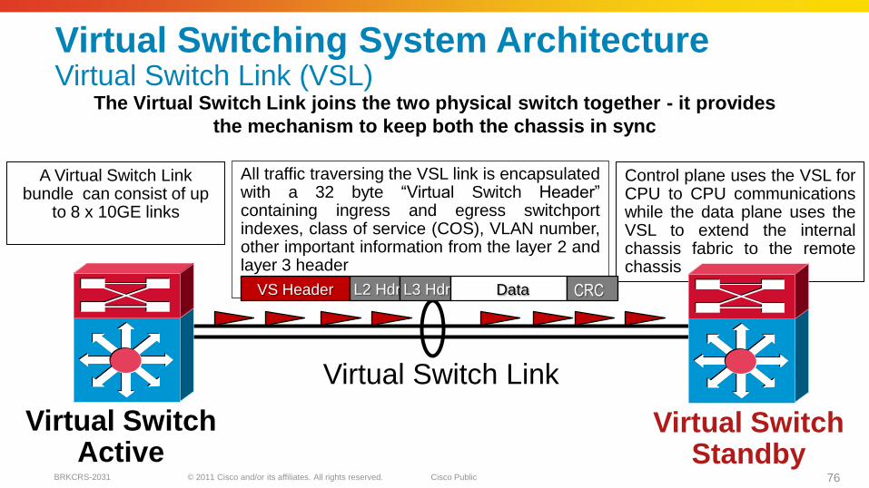
Virtual Switching System ArchitectureVirtual Switch Link (VSL)
The Virtual Switch Link joins the two physical switch together - it provides
the mechanism to keep both the chassis in sync
A Virtual Switch Link bundle can consist of up
to 8 x 10GE links
All traffic traversing the VSL link is encapsulatedwith a 32 byte ―Virtual Switch Header‖containing ingress and egress switchportindexes, class of service (COS), VLAN number,other important information from the layer 2 andlayer 3 header
Control plane uses the VSL forCPU to CPU communicationswhile the data plane uses theVSL to extend the internalchassis fabric to the remotechassis
Virtual Switch Active
Virtual Switch Standby
Virtual Switch Link
VS Header L2 Hdr L3 Hdr Data CRC
© 2011 Cisco and/or its affiliates. All rights reserved. Cisco PublicBRKCRS-2031 77
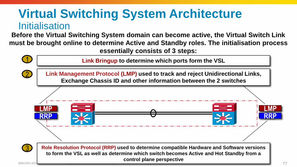
Virtual Switching System ArchitectureInitialisation
Before the Virtual Switching System domain can become active, the Virtual Switch Link
must be brought online to determine Active and Standby roles. The initialisation process
essentially consists of 3 steps:
Role Resolution Protocol (RRP) used to determine compatible Hardware and Software versions
to form the VSL as well as determine which switch becomes Active and Hot Standby from a
control plane perspective
LMPRRP
Link Management Protocol (LMP) used to track and reject Unidirectional Links,
Exchange Chassis ID and other information between the 2 switches
Link Bringup to determine which ports form the VSL1
2
3
LMPRRP
© 2011 Cisco and/or its affiliates. All rights reserved. Cisco PublicBRKCRS-2031 78
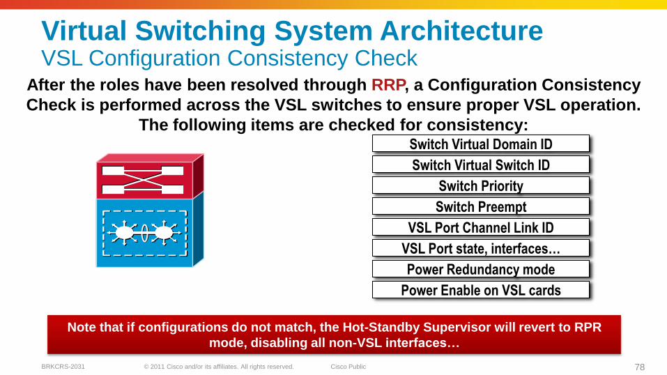
Virtual Switching System ArchitectureVSL Configuration Consistency Check
After the roles have been resolved through RRP, a Configuration Consistency
Check is performed across the VSL switches to ensure proper VSL operation.
The following items are checked for consistency:Switch Virtual Domain ID
Switch Virtual Switch ID
Switch Priority
Switch Preempt
VSL Port Channel Link ID
VSL Port state, interfaces…
Power Redundancy mode
Power Enable on VSL cards
Note that if configurations do not match, the Hot-Standby Supervisor will revert to RPR
mode, disabling all non-VSL interfaces…
Virtual Switch
© 2011 Cisco and/or its affiliates. All rights reserved. Cisco PublicBRKCRS-2031 79
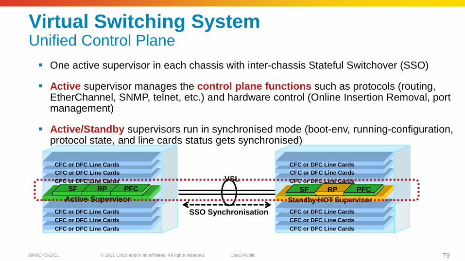
Virtual Switching SystemUnified Control Plane
One active supervisor in each chassis with inter-chassis Stateful Switchover (SSO)
Active supervisor manages the control plane functions such as protocols (routing, EtherChannel, SNMP, telnet, etc.) and hardware control (Online Insertion Removal, port management)
Active/Standby supervisors run in synchronised mode (boot-env, running-configuration, protocol state, and line cards status gets synchronised)
Active Supervisor
SF RP PFC
CFC or DFC Line Cards
CFC or DFC Line Cards
CFC or DFC Line Cards
CFC or DFC Line Cards
CFC or DFC Line Cards
Standby HOT Supervisor
SF RP PFC
VSLCFC or DFC Line Cards
CFC or DFC Line Cards
CFC or DFC Line Cards
CFC or DFC Line Cards
CFC or DFC Line Cards
CFC or DFC Line Cards
CFC or DFC Line Cards
SSO Synchronisation
© 2011 Cisco and/or its affiliates. All rights reserved. Cisco PublicBRKCRS-2031 80
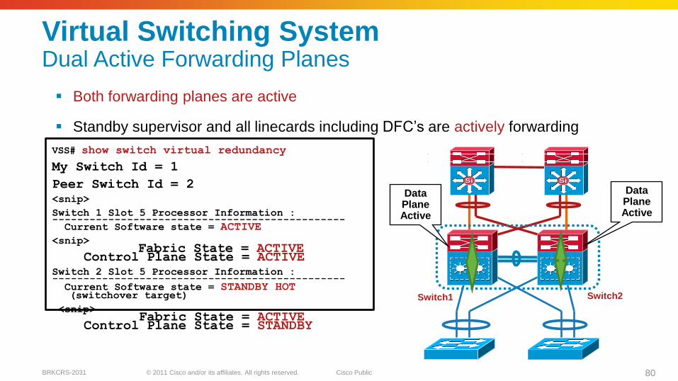
Virtual Switching SystemDual Active Forwarding Planes
Both forwarding planes are active
Standby supervisor and all linecards including DFC’s are actively forwarding
VSS# show switch virtual redundancy
My Switch Id = 1
Peer Switch Id = 2
<snip>
Switch 1 Slot 5 Processor Information :-----------------------------------------------Current Software state = ACTIVE
<snip>Fabric State = ACTIVE
Control Plane State = ACTIVE
Switch 2 Slot 5 Processor Information :-----------------------------------------------Current Software state = STANDBY HOT (switchover target)
<snip>Fabric State = ACTIVE
Control Plane State = STANDBY
Data PlaneActive
Data Plane Active
SiSiSiSi
Switch1 Switch2
© 2011 Cisco and/or its affiliates. All rights reserved. Cisco PublicBRKCRS-2031 81
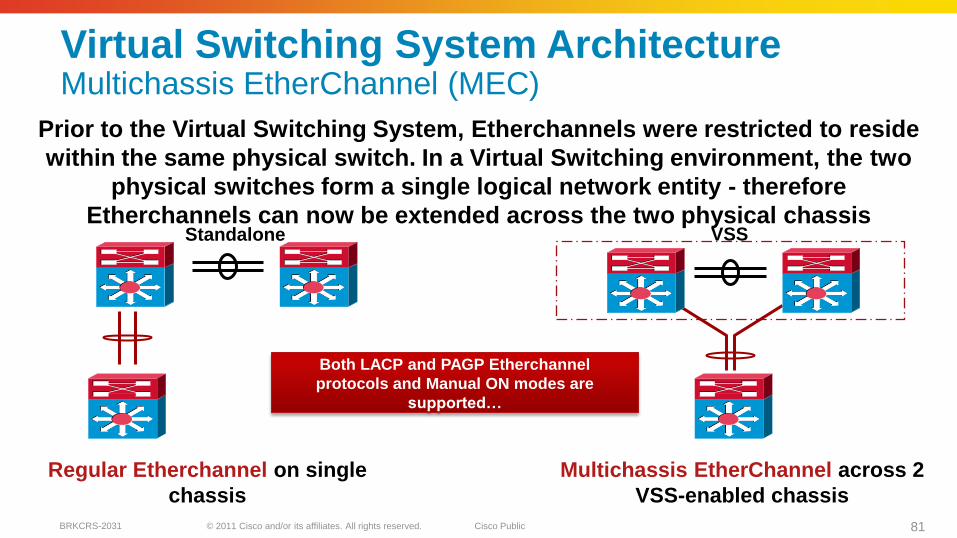
Virtual Switching System ArchitectureMultichassis EtherChannel (MEC)
Prior to the Virtual Switching System, Etherchannels were restricted to reside
within the same physical switch. In a Virtual Switching environment, the two
physical switches form a single logical network entity - therefore
Etherchannels can now be extended across the two physical chassis
Regular Etherchannel on single
chassis
Multichassis EtherChannel across 2
VSS-enabled chassis
VSS
Both LACP and PAGP Etherchannel
protocols and Manual ON modes are
supported…
Standalone
© 2011 Cisco and/or its affiliates. All rights reserved. Cisco PublicBRKCRS-2031 82
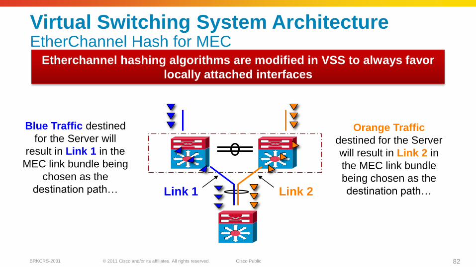
Virtual Switching System ArchitectureEtherChannel Hash for MEC
Link 1 Link 2
Etherchannel hashing algorithms are modified in VSS to always favor
locally attached interfaces
Blue Traffic destined
for the Server will
result in Link 1 in the
MEC link bundle being
chosen as the
destination path…
Orange Traffic
destined for the Server
will result in Link 2 in
the MEC link bundle
being chosen as the
destination path…
© 2011 Cisco and/or its affiliates. All rights reserved. Cisco PublicBRKCRS-2031 83
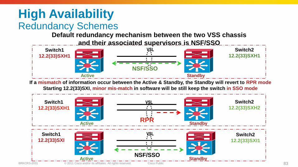
High AvailabilityRedundancy Schemes
Default redundancy mechanism between the two VSS chassis
and their associated supervisors is NSF/SSOVSL
If a mismatch of information occur between the Active & Standby, the Standby will revert to RPR mode
Starting 12.2(33)SXI, minor mis-match in software will be still keep the switch in SSO mode
Switch1
12.2(33)SXH1
Switch2
12.2(33)SXH1
Switch1
12.2(33)SXH1
Switch2
12.2(33)SXH2
Active Standby
Active Standby
VSL
RPR
Switch1
12.2(33)SXISwitch2
12.2(33)SXI1
Active Standby
VSL
NSF/SSO
NSF/SSO
© 2011 Cisco and/or its affiliates. All rights reserved. Cisco PublicBRKCRS-2031 84
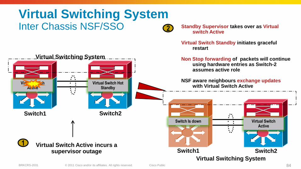
Virtual Switch Hot Standby
Virtual Switch Active
Virtual Switching System
Virtual Switch Active
Switch Is down
Virtual Switch Active incurs a supervisor outage
1
2 Standby Supervisor takes over as Virtual switch Active
Virtual Switch Standby initiates graceful restart
Non Stop forwarding of packets will continue using hardware entries as Switch-2 assumes active role
NSF aware neighbours exchange updates with Virtual Switch Active
Switch1 Switch2
Switch2Switch1
Virtual Switching System
Virtual Switching SystemInter Chassis NSF/SSO
© 2011 Cisco and/or its affiliates. All rights reserved. Cisco PublicBRKCRS-2031 85
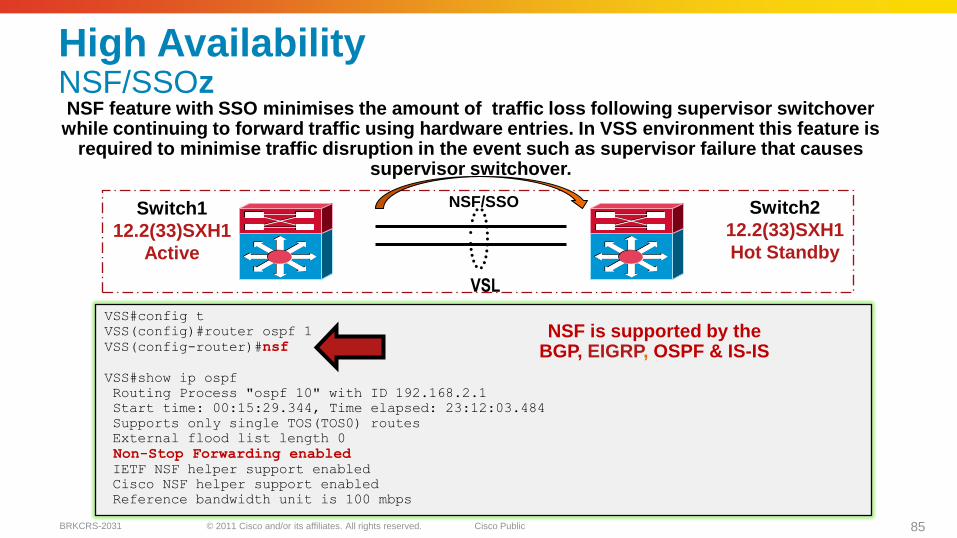
VSL
Switch1
12.2(33)SXH1
Active
Switch2
12.2(33)SXH1
Hot Standby
NSF feature with SSO minimises the amount of traffic loss following supervisor switchover while continuing to forward traffic using hardware entries. In VSS environment this feature is
required to minimise traffic disruption in the event such as supervisor failure that causes supervisor switchover.
VSS#config t
VSS(config)#router ospf 1
VSS(config-router)#nsf
VSS#show ip ospf
Routing Process "ospf 10" with ID 192.168.2.1
Start time: 00:15:29.344, Time elapsed: 23:12:03.484
Supports only single TOS(TOS0) routes
External flood list length 0
Non-Stop Forwarding enabledIETF NSF helper support enabled
Cisco NSF helper support enabled
Reference bandwidth unit is 100 mbps
NSF is supported by the BGP, EIGRP, OSPF & IS-IS
NSF/SSO
High AvailabilityNSF/SSOz
© 2011 Cisco and/or its affiliates. All rights reserved. Cisco PublicBRKCRS-2031 86
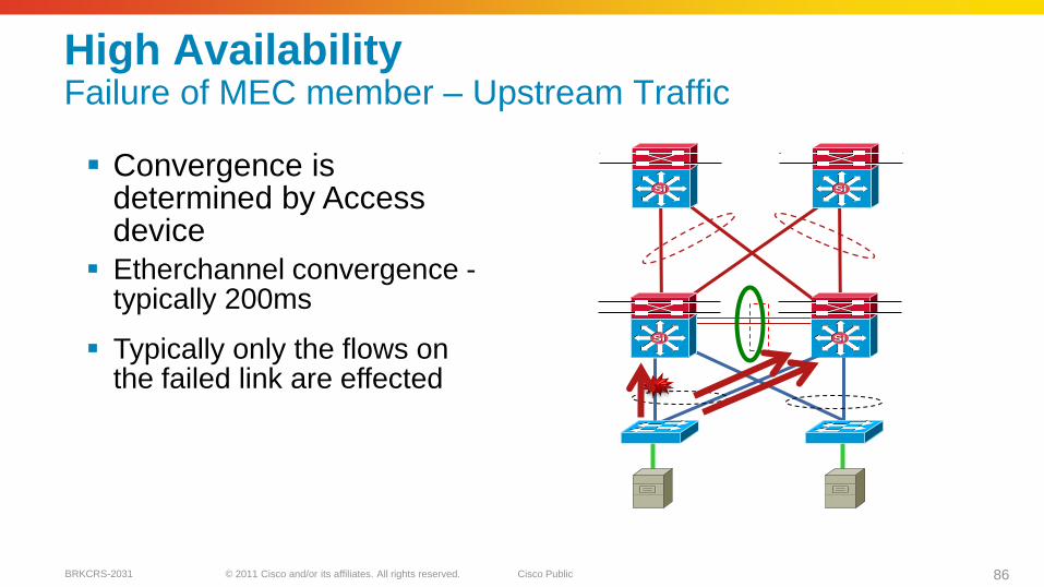
High AvailabilityFailure of MEC member – Upstream Traffic
SiSi SiSi
SiSi SiSi
Convergence is determined by Access device
Etherchannel convergence -typically 200ms
Typically only the flows on the failed link are effected
© 2011 Cisco and/or its affiliates. All rights reserved. Cisco PublicBRKCRS-2031 87
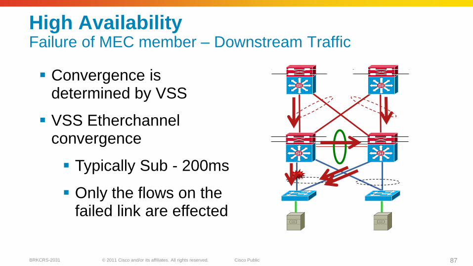
High AvailabilityFailure of MEC member – Downstream Traffic
SiSi SiSi
SiSi SiSi
Convergence is determined by VSS
VSS Etherchannelconvergence
Typically Sub - 200ms
Only the flows on the failed link are effected
© 2011 Cisco and/or its affiliates. All rights reserved. Cisco PublicBRKCRS-2031 88
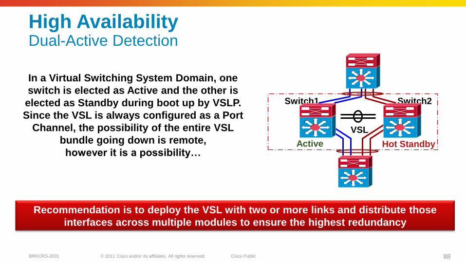
High AvailabilityDual-Active Detection
In a Virtual Switching System Domain, one
switch is elected as Active and the other is
elected as Standby during boot up by VSLP.
Since the VSL is always configured as a Port
Channel, the possibility of the entire VSL
bundle going down is remote,
however it is a possibility…
Recommendation is to deploy the VSL with two or more links and distribute those
interfaces across multiple modules to ensure the highest redundancy
Active Hot Standby
Switch1 Switch2
VSL
© 2011 Cisco and/or its affiliates. All rights reserved. Cisco PublicBRKCRS-2031 89
Active
Switch1 Switch2
VSL
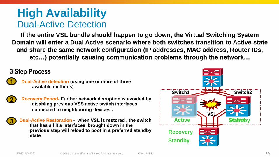
High AvailabilityDual-Active Detection
If the entire VSL bundle should happen to go down, the Virtual Switching System
Domain will enter a Dual Active scenario where both switches transition to Active state
and share the same network configuration (IP addresses, MAC address, Router IDs,
etc…) potentially causing communication problems through the network…
3 Step Process
Dual-Active detection (using one or more of three available methods)
1
Recovery Period- Further network disruption is avoided by disabling previous VSS active switch interfaces
connected to neighbouring devices .
2
Dual-Active Restoration - when VSL is restored , the switch that has all it‘s interfaces brought down in the previous step will reload to boot in a preferred standby state
3 Active
Recovery
Standby
Standby
© 2011 Cisco and/or its affiliates. All rights reserved. Cisco PublicBRKCRS-2031 90
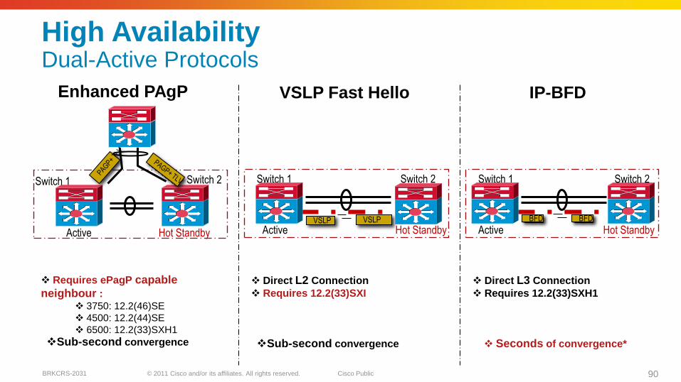
Enhanced PAgP
Hot StandbyActive
Switch 1 Switch 2
IP-BFD
Switch 1
VSLP VSLP BFD BFD
Switch 2
Hot StandbyActive
Switch 1 Switch 2
Hot StandbyActive
VSLP Fast Hello
Requires ePagP capable
neighbour :
3750: 12.2(46)SE
4500: 12.2(44)SE
6500: 12.2(33)SXH1
Direct L2 Connection
Requires 12.2(33)SXI
Direct L3 Connection
Requires 12.2(33)SXH1
Sub-second convergence Sub-second convergence Seconds of convergence*
High AvailabilityDual-Active Protocols
© 2011 Cisco and/or its affiliates. All rights reserved. Cisco PublicBRKCRS-2031 91
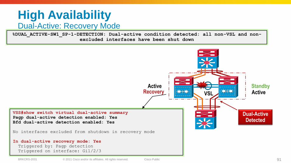
VSL
%DUAL_ACTIVE-SW1_SP-1-DETECTION: Dual-active condition detected: all non-VSL and non-
excluded interfaces have been shut down
VSS#show switch virtual dual-active summary
Pagp dual-active detection enabled: Yes
Bfd dual-active detection enabled: Yes
No interfaces excluded from shutdown in recovery mode
In dual-active recovery mode: Yes
Triggered by: Pagp detection
Triggered on interface: Gi1/2/3
Dual-Active Detected
Active Standby
High AvailabilityDual-Active: Recovery Mode
ActiveRecovery
© 2011 Cisco and/or its affiliates. All rights reserved. Cisco PublicBRKCRS-2031 92
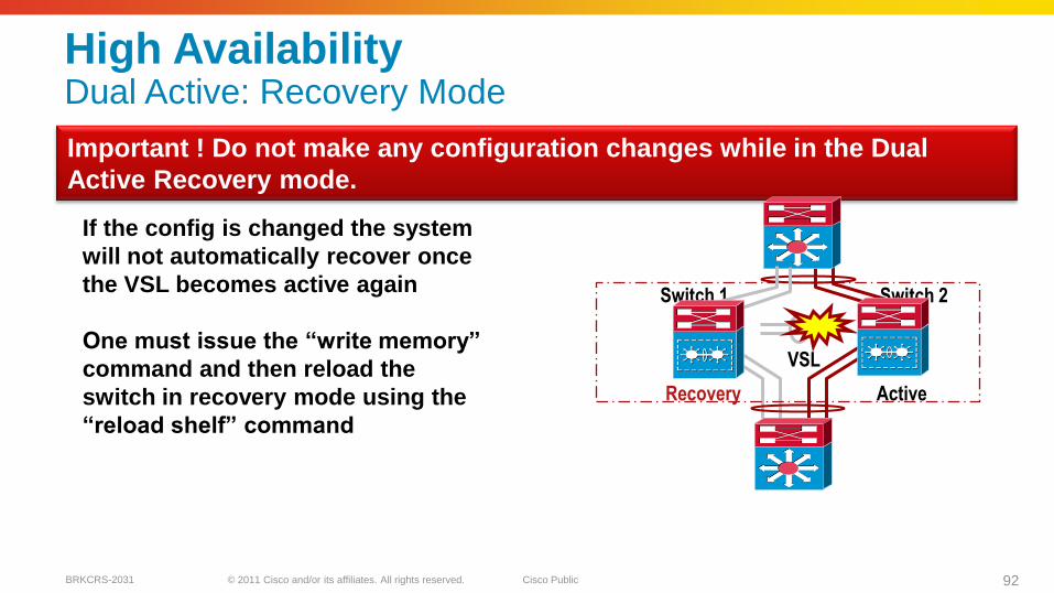
High AvailabilityDual Active: Recovery Mode
Important ! Do not make any configuration changes while in the Dual
Active Recovery mode.
Switch 1 Switch 2
VSL
Recovery Active
If the config is changed the system
will not automatically recover once
the VSL becomes active again
One must issue the ―write memory‖
command and then reload the
switch in recovery mode using the
―reload shelf‖ command
© 2011 Cisco and/or its affiliates. All rights reserved. Cisco PublicBRKCRS-2031 93
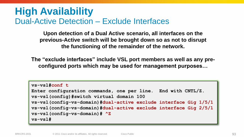
High AvailabilityDual-Active Detection – Exclude Interfaces
Upon detection of a Dual Active scenario, all interfaces on the
previous-Active switch will be brought down so as not to disrupt
the functioning of the remainder of the network.
The ―exclude interfaces‖ include VSL port members as well as any pre-
configured ports which may be used for management purposes…
vs-vsl#conf t
Enter configuration commands, one per line. End with CNTL/Z.
vs-vsl(config)#switch virtual domain 100
vs-vsl(config-vs-domain)#dual-active exclude interface Gig 1/5/1
vs-vsl(config-vs-domain)#dual-active exclude interface Gig 2/5/1
vs-vsl(config-vs-domain)# ^Z
vs-vsl#
© 2011 Cisco and/or its affiliates. All rights reserved. Cisco PublicBRKCRS-2031 94
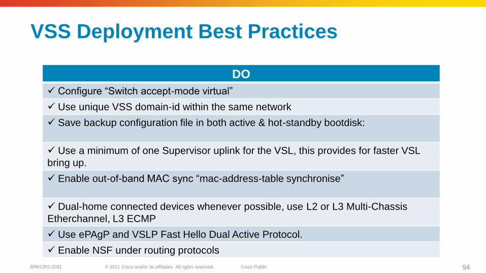
DO
Configure ―Switch accept-mode virtual‖
Use unique VSS domain-id within the same network
Save backup configuration file in both active & hot-standby bootdisk:
Use a minimum of one Supervisor uplink for the VSL, this provides for faster VSL
bring up.
Enable out-of-band MAC sync ―mac-address-table synchronise‖
Dual-home connected devices whenever possible, use L2 or L3 Multi-Chassis
Etherchannel, L3 ECMP
Use ePAgP and VSLP Fast Hello Dual Active Protocol.
Enable NSF under routing protocols
VSS Deployment Best Practices
© 2011 Cisco and/or its affiliates. All rights reserved. Cisco PublicBRKCRS-2031 95
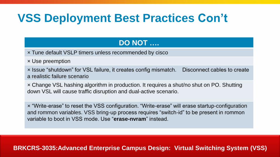
DO NOT ….
× Tune default VSLP timers unless recommended by cisco
× Use preemption
× Issue ―shutdown‖ for VSL failure, it creates config mismatch. Disconnect cables to create
a realistic failure scenario
× Change VSL hashing algorithm in production. It requires a shut/no shut on PO. Shutting
down VSL will cause traffic disruption and dual-active scenario.
× ―Write-erase‖ to reset the VSS configuration. ―Write-erase‖ will erase startup-configuration
and rommon variables. VSS bring-up process requires ―switch-id‖ to be present in rommon
variable to boot in VSS mode. Use ―erase-nvram‖ instead.
VSS Deployment Best Practices Con‘t
BRKCRS-3035:Advanced Enterprise Campus Design: Virtual Switching System (VSS)

© 2011 Cisco and/or its affiliates. All rights reserved. Cisco PublicBRKCRS-2031 96
Agenda
Multilayer Campus Design Principles
Foundation Services
Campus Design Best Practices
VSS Distribution Block
Security Considerations
Putting It All Together
Summary
SiSiSiSi
SiSiSiSi
SiSi
Data Centre
SiSi SiSi
Services
Block
Distribution Blocks
SiSi SiSi SiSi
© 2011 Cisco and/or its affiliates. All rights reserved. Cisco PublicBRKCRS-2031 97
WAN Internet
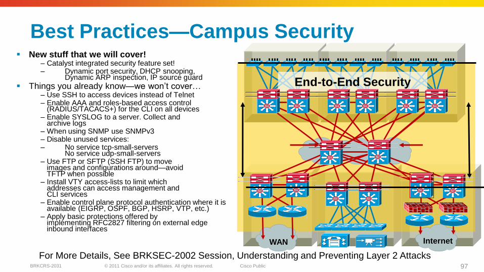
End-to-End Security
SiSi SiSi SiSi SiSi SiSi SiSi
SiSiSiSi
SiSiSiSi
SiSi SiSiSiSiSiSi
Best Practices—Campus Security New stuff that we will cover!
– Catalyst integrated security feature set!– Dynamic port security, DHCP snooping,
Dynamic ARP inspection, IP source guard
Things you already know—we won’t cover…– Use SSH to access devices instead of Telnet – Enable AAA and roles-based access control
(RADIUS/TACACS+) for the CLI on all devices – Enable SYSLOG to a server. Collect and
archive logs– When using SNMP use SNMPv3– Disable unused services: – No service tcp-small-servers
No service udp-small-servers – Use FTP or SFTP (SSH FTP) to move
images and configurations around—avoid TFTP when possible
– Install VTY access-lists to limit which addresses can access management and CLI services
– Enable control plane protocol authentication where it is available (EIGRP, OSPF, BGP, HSRP, VTP, etc.)
– Apply basic protections offered by implementing RFC2827 filtering on external edge inbound interfaces
For More Details, See BRKSEC-2002 Session, Understanding and Preventing Layer 2 Attacks
© 2011 Cisco and/or its affiliates. All rights reserved. Cisco PublicBRKCRS-2031 98
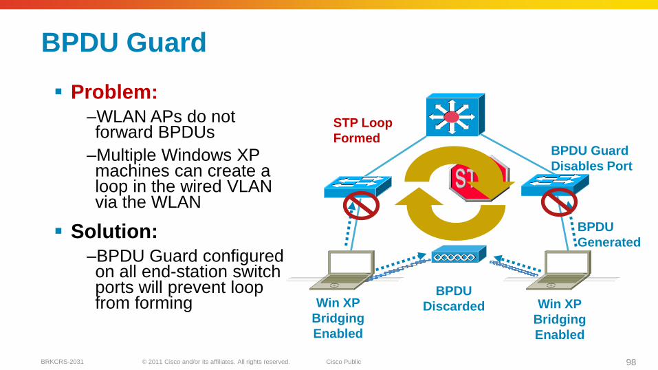
BPDU Guard
Problem:
–WLAN APs do notforward BPDUs
–Multiple Windows XPmachines can create aloop in the wired VLANvia the WLAN
Solution:
–BPDU Guard configuredon all end-station switch ports will prevent loopfrom forming Win XP
Bridging
Enabled
Win XP
Bridging
Enabled
BPDU Guard
Disables Port
STP Loop
Formed
BPDU
Generated
BPDU
Discarded
Prevent Loops via WLAN (Windows XP Bridging)
© 2011 Cisco and/or its affiliates. All rights reserved. Cisco PublicBRKCRS-2031 99
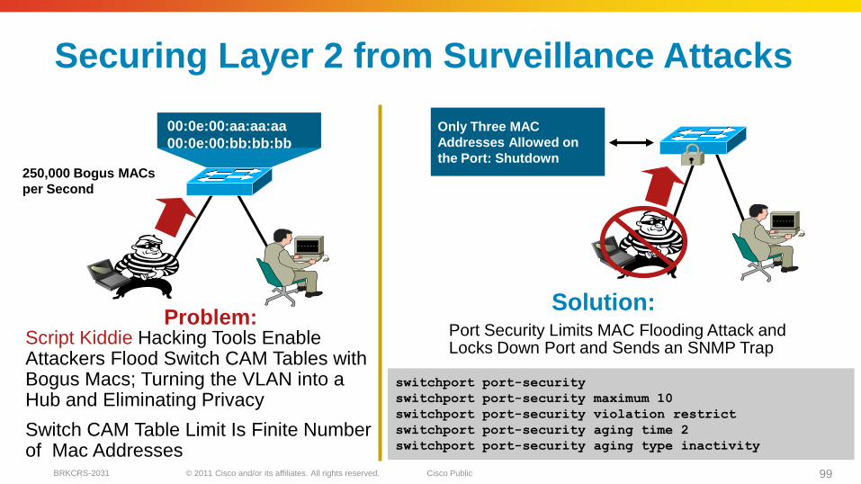
Port Security Limits MAC Flooding Attack and Locks Down Port and Sends an SNMP Trap
00:0e:00:aa:aa:aa
00:0e:00:bb:bb:bb
Script Kiddie Hacking Tools Enable Attackers Flood Switch CAM Tables with Bogus Macs; Turning the VLAN into a Hub and Eliminating Privacy
Switch CAM Table Limit Is Finite Number of Mac Addresses
Only Three MAC
Addresses Allowed on
the Port: Shutdown250,000 Bogus MACs
per Second
Problem:Solution:
switchport port-security
switchport port-security maximum 10
switchport port-security violation restrict
switchport port-security aging time 2
switchport port-security aging type inactivity
Securing Layer 2 from Surveillance AttacksCutting Off MAC-Based Attacks
© 2011 Cisco and/or its affiliates. All rights reserved. Cisco PublicBRKCRS-2031 100
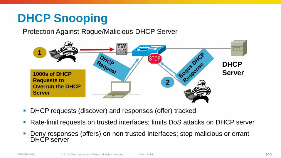
DHCP Snooping
DHCP requests (discover) and responses (offer) tracked
Rate-limit requests on trusted interfaces; limits DoS attacks on DHCP server
Deny responses (offers) on non trusted interfaces; stop malicious or errant DHCP server
DHCP
Server1000s of DHCP Requests to Overrun the DHCP Server
1
2
Protection Against Rogue/Malicious DHCP Server
© 2011 Cisco and/or its affiliates. All rights reserved. Cisco PublicBRKCRS-2031 101
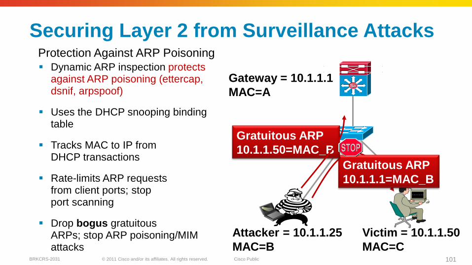
Securing Layer 2 from Surveillance Attacks
Dynamic ARP inspection protects against ARP poisoning (ettercap, dsnif, arpspoof)
Uses the DHCP snooping binding table
Tracks MAC to IP from DHCP transactions
Rate-limits ARP requests from client ports; stop port scanning
Drop bogus gratuitous ARPs; stop ARP poisoning/MIMattacks
SiSiGateway = 10.1.1.1
MAC=A
Attacker = 10.1.1.25
MAC=B
Victim = 10.1.1.50
MAC=C
Gratuitous ARP
10.1.1.1=MAC_B
Gratuitous ARP
10.1.1.50=MAC_B
Protection Against ARP Poisoning
© 2011 Cisco and/or its affiliates. All rights reserved. Cisco PublicBRKCRS-2031 102
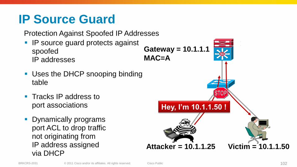
IP Source Guard
IP source guard protects against spoofed IP addresses
Uses the DHCP snooping binding table
Tracks IP address to port associations
Dynamically programs port ACL to drop traffic not originating from IP address assigned via DHCP
SiSiGateway = 10.1.1.1
MAC=A
Attacker = 10.1.1.25 Victim = 10.1.1.50
Hey, I‘m 10.1.1.50 !
Protection Against Spoofed IP Addresses
© 2011 Cisco and/or its affiliates. All rights reserved. Cisco PublicBRKCRS-2031 103
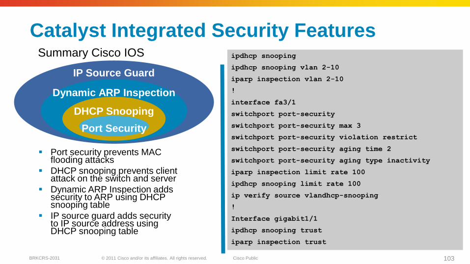
Catalyst Integrated Security Features
Port security prevents MAC flooding attacks
DHCP snooping prevents client attack on the switch and server
Dynamic ARP Inspection addssecurity to ARP using DHCP snooping table
IP source guard adds security to IP source address using DHCP snooping table
ipdhcp snooping
ipdhcp snooping vlan 2-10
iparp inspection vlan 2-10
!
interface fa3/1
switchport port-security
switchport port-security max 3
switchport port-security violation restrict
switchport port-security aging time 2
switchport port-security aging type inactivity
iparp inspection limit rate 100
ipdhcp snooping limit rate 100
ip verify source vlandhcp-snooping
!
Interface gigabit1/1
ipdhcp snooping trust
iparp inspection trust
IP Source Guard
Dynamic ARP Inspection
DHCP Snooping
Port Security
Summary Cisco IOS

© 2011 Cisco and/or its affiliates. All rights reserved. Cisco PublicBRKCRS-2031 104
Agenda
Multilayer Campus Design Principles
Foundation Services
Campus Design Best Practices
VSS Distribution Block
Security Considerations
Putting It All Together
Summary
SiSiSiSi
SiSiSiSi
SiSi
Data Centre
SiSi SiSi
Services
Block
Distribution Blocks
SiSi SiSi SiSi
© 2011 Cisco and/or its affiliates. All rights reserved. Cisco PublicBRKCRS-2031 105
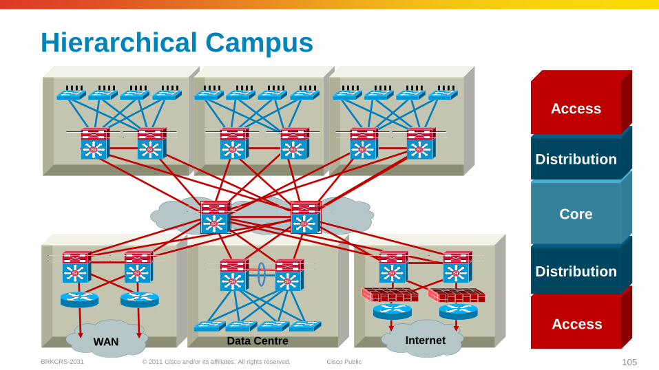
Hierarchical Campus
Data CentreWAN Internet
Access
Distribution
Core
Distribution
Access
SiSi SiSi SiSi SiSi SiSi SiSi
SiSi SiSi
SiSi SiSi
SiSi SiSi
SiSi SiSi
© 2011 Cisco and/or its affiliates. All rights reserved. Cisco PublicBRKCRS-2031 106
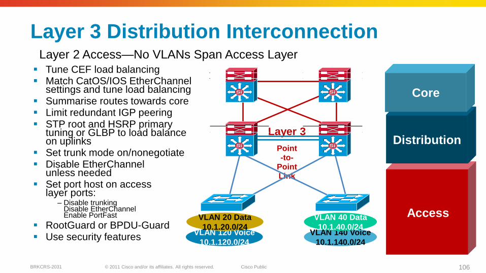
VLAN 140 Voice
10.1.140.0/24
Layer 3 Distribution Interconnection
Tune CEF load balancing Match CatOS/IOS EtherChannel
settings and tune load balancing Summarise routes towards core Limit redundant IGP peering STP root and HSRP primary
tuning or GLBP to load balance on uplinks
Set trunk mode on/nonegotiate Disable EtherChannel
unless needed Set port host on access
layer ports:– Disable trunking
Disable EtherChannelEnable PortFast
RootGuard or BPDU-Guard Use security features
Point -to-
Point Link
Layer 3
Access
Distribution
Core
Layer 2 Access—No VLANs Span Access Layer
VLAN 120 Voice
10.1.120.0/24
VLAN 20 Data
10.1.20.0/24
VLAN 40 Data
10.1.40.0/24
SiSi SiSi
SiSi SiSi
© 2011 Cisco and/or its affiliates. All rights reserved. Cisco PublicBRKCRS-2031 107
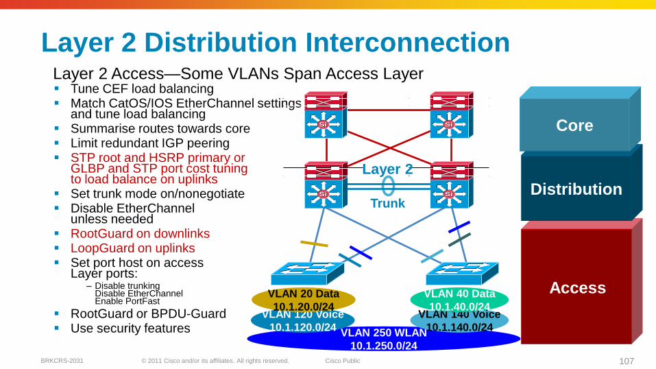
Layer 2 Distribution Interconnection
Tune CEF load balancing Match CatOS/IOS EtherChannel settings
and tune load balancing Summarise routes towards core Limit redundant IGP peering STP root and HSRP primary or
GLBP and STP port cost tuning to load balance on uplinks
Set trunk mode on/nonegotiate Disable EtherChannel
unless needed RootGuard on downlinks LoopGuard on uplinks Set port host on access
Layer ports:– Disable trunking
Disable EtherChannelEnable PortFast
RootGuard or BPDU-Guard Use security features VLAN 250 WLAN
10.1.250.0/24
VLAN 120 Voice
10.1.120.0/24
Trunk
VLAN 20 Data
10.1.20.0/24VLAN 140 Voice
10.1.140.0/24
VLAN 40 Data
10.1.40.0/24
SiSi SiSi
SiSi SiSi
Layer 2
Layer 2 Access—Some VLANs Span Access Layer
Access
Distribution
Core
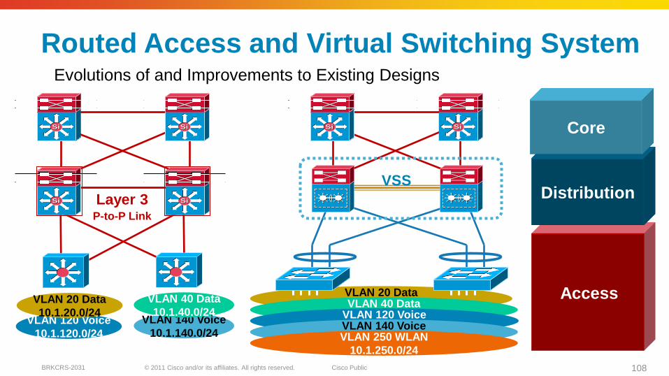
© 2011 Cisco and/or its affiliates. All rights reserved. Cisco PublicBRKCRS-2031 108
VLAN 20 Data
10.1.20.0/24
Routed Access and Virtual Switching System
VLAN 120 Voice
10.1.120.0/24
P-to-P Link
Layer 3
VLAN 20 Data
10.1.20.0/24VLAN 140 Voice
10.1.140.0/24
VLAN 40 Data
10.1.40.0/24
SiSi SiSi
SiSi SiSi
VLAN 40 Data
10.1.40.0/24
VSS
VLAN 120 Voice
10.1.120.0/24VLAN 140 Voice
10.1.140.0/24
Evolutions of and Improvements to Existing Designs
Access
Distribution
Core
VLAN 250 WLAN
10.1.250.0/24
SiSi SiSi
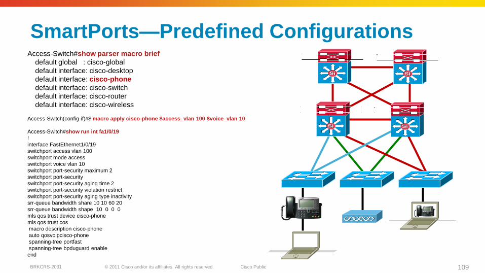
© 2011 Cisco and/or its affiliates. All rights reserved. Cisco PublicBRKCRS-2031 109
SmartPorts—Predefined ConfigurationsAccess-Switch#show parser macro brief
default global : cisco-global
default interface: cisco-desktop
default interface: cisco-phone
default interface: cisco-switch
default interface: cisco-router
default interface: cisco-wireless
Access-Switch(config-if)#$ macro apply cisco-phone $access_vlan 100 $voice_vlan 10
Access-Switch#show run int fa1/0/19
!
interface FastEthernet1/0/19
switchport access vlan 100
switchport mode access
switchport voice vlan 10
switchport port-security maximum 2
switchport port-security
switchport port-security aging time 2
switchport port-security violation restrict
switchport port-security aging type inactivity
srr-queue bandwidth share 10 10 60 20
srr-queue bandwidth shape 10 0 0 0
mls qos trust device cisco-phone
mls qos trust cos
macro description cisco-phone
auto qosvoipcisco-phone
spanning-tree portfast
spanning-tree bpduguard enable
end
SiSiSiSi
SiSi SiSi
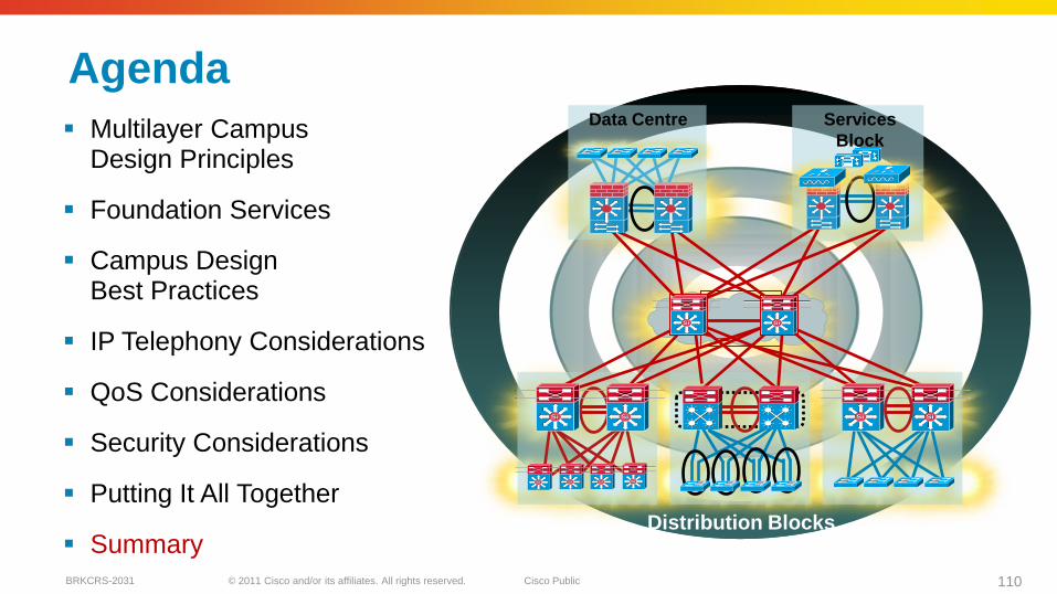
© 2011 Cisco and/or its affiliates. All rights reserved. Cisco PublicBRKCRS-2031 110
Agenda
Multilayer Campus Design Principles
Foundation Services
Campus Design Best Practices
IP Telephony Considerations
QoS Considerations
Security Considerations
Putting It All Together
Summary
SiSiSiSi
SiSiSiSi
SiSi
Data Centre
SiSi SiSi
Services
Block
Distribution Blocks
SiSi SiSi SiSi
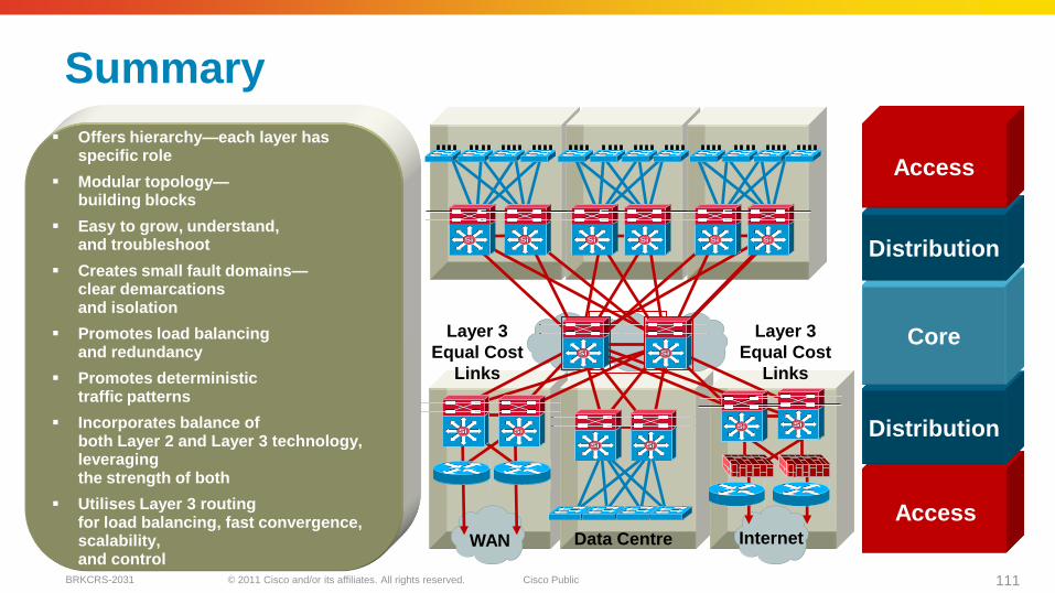
© 2011 Cisco and/or its affiliates. All rights reserved. Cisco PublicBRKCRS-2031 111
Summary
Offers hierarchy—each layer has specific role
Modular topology—building blocks
Easy to grow, understand, and troubleshoot
Creates small fault domains— Clear demarcations and isolation
Promotes load balancing and redundancy
Promotes deterministic traffic patterns
Incorporates balance of both Layer 2 and Layer 3 technology, leveraging the strength of both
Utilizes Layer 3 routing for load balancing, fast convergence, scalability, and control
Data CentreWAN Internet
Layer 3
Equal Cost
Links
Layer 3
Equal Cost
Links
Access
Distribution
Core
Distribution
Access
SiSi SiSi SiSi SiSi SiSi SiSi
SiSi SiSi
SiSi SiSi
SiSi SiSi
SiSi SiSi
Offers hierarchy—each layer has specific role
Modular topology—building blocks
Easy to grow, understand, and troubleshoot
Creates small fault domains—clear demarcations and isolation
Promotes load balancing and redundancy
Promotes deterministic traffic patterns
Incorporates balance of both Layer 2 and Layer 3 technology, leveraging the strength of both
Utilises Layer 3 routing for load balancing, fast convergence, scalability, and control

© 2011 Cisco and/or its affiliates. All rights reserved. Cisco Public 112BRKCRS-2031
Q and A
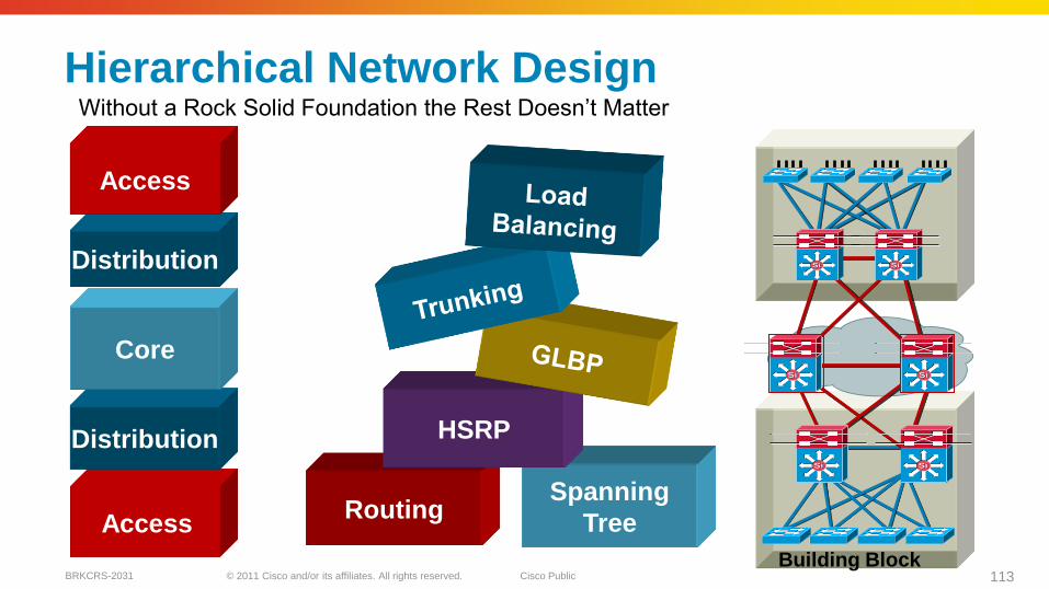
© 2011 Cisco and/or its affiliates. All rights reserved. Cisco PublicBRKCRS-2031 113
Hierarchical Network Design
Spanning
TreeRouting
HSRP
Access
Distribution
Core
Distribution
Access
Building Block
SiSi SiSi
SiSi SiSi
SiSi SiSi
Without a Rock Solid Foundation the Rest Doesn’t Matter
© 2011 Cisco and/or its affiliates. All rights reserved. Cisco PublicBRKCRS-2031 114
Reference Materials—Design Zone
High Availability Campus Design Guide
High Availability Campus Convergence Analysis
High Availability Campus Design Guide—Routed Access EIGRP and OSPF
http://www.cisco.com/go/srnd
© 2011 Cisco and/or its affiliates. All rights reserved. Cisco PublicBRKCRS-2031 115
Complete Your Online Session Evaluation
Complete your session evaluation:
Directly from your mobile device by visiting www.ciscoliveaustralia.com/mobile and login by entering your badge ID (located on the front of your badge)
Visit one of the Cisco Live internet stations located throughout the venue
Open a browser on your own computer to access the Cisco Live onsite portal