Embed Size (px)
Citation preview

FOMFOM
Multilayer fabrication at FOMMultilayer fabrication at FOM
Fred Bijkerk, Eric Louis,Fred Bijkerk, Eric Louis,
Andre Yakshin, Robbert vd Kruijs, Erwin Zoethout, Sergiy Dobrovolsky, Malcom Wu,Andre Yakshin, Robbert vd Kruijs, Erwin Zoethout, Sergiy Dobrovolsky, Malcom Wu,
Ileana Nedelcu, Tim Tsarfati, Véronique Lohmann, Saskia Bruijn,Ileana Nedelcu, Tim Tsarfati, Véronique Lohmann, Saskia Bruijn,
Edward Maas, Santi Alonso vd Westen, Fabian Wahle, Kees Grootkarzijn, Peter Sallé, Edward Maas, Santi Alonso vd Westen, Fabian Wahle, Kees Grootkarzijn, Peter Sallé, Arend Jan van CalcarArend Jan van Calcar ,,
FOM Institute for Plasma Physics RijnhuizenFOM Institute for Plasma Physics Rijnhuizen
Nieuwegein, The NetherlandsNieuwegein, The Netherlands
[email protected]@rijnhuizen.nl

2
FOMFOMEUV lithography reqts on optics substratesEUV lithography reqts on optics substrates
1.4
86
m
Reticle-stage
wafer stage
SPF
GratingCollector
Wafer level
FF
PF
G
N1
N2Collector-
Source-Unit
Illuminator-
Unit
Stop
1m
Design example
European EUVL Process
Development tool

3
FOMFOMEUV imaging diagnosticsEUV imaging diagnostics
EUV telescope to measure narrow-band
size of EUV sources
EUV telescope images can differ
considerably from results pinhole imaging•EUV imaging: >40% smaller source size
•Up to 20% EUV energy in source tail
364 ±11 m FWHM
98
510 ±28 m FWHM
102
Broad band EUV pinhole image
In-band EUV ML
telescope image 0
0.1
0.2
0.3
0.4
0.5
0.6
0.7
0.8
0.9
1
0 500 1000 1500 2000
length (μm)
norm
alis
ed in
tensi
ty
In-band
Broad-band
Philips EUV Xe source

4
FOMFOM
Principle
• Bi-layer systems: reflecting & spacer layers
• Summation of in-phase partial reflections
Design/simulation/analysis
• Bragg condition: n = 2d sin (1- sin2c /sin2 )1/2
• Fresnel equations + roughness models
• DW-factor: R = R0 exp (-k (sin . )2 / )
• -ratio: dreflecting / (dreflecting + dspacer)
• Complex indices of refraction, atomic scattering factors f1, f2, density
Deposition processes
• Optimize combination materials + optical properties
• Thin film materials growth process
• Controlled low interface roughness & intermixing of layers
• Regular, reproducible stack without layer thickness errors
Multilayer reflectionMultilayer reflection
incident XUV radiation
= 0,1 - 30 nm
reflecting material
spacer
d-spacing
•Bragg: n = 2d sin (1- sin2c /sin2 )1/2

5
FOMFOMMultilayer ReqtsMultilayer Reqts
- Near-theoretical values of reflectivity
-13.5 nm @ normal incidence
- Lateral uniformity within 0.1%
-Gradients and flat profiles over 500 mm dia
- Unprecedented temporal/thermal stability
- Extreme radiation hardness: 3x10⁴ h to R/R 1%
-Moderate vacuum conditions
- Contamination: 1% over 3x10⁴ h
ref Louis et al, Microelectr. Engin. 27 (1995) 235-238
theoretical maximum
measured 64%
(40 layer pairs)
12 12.5 13 13.5 14 14.5 15
Status <1998
0
10
20
30
40
50
60
70
Progress in coating research twice higher
total throughput of ten-mirror EUVL system
70.15% @ 13.5 nm
70.5% @ 13.3 nm
Wavelength, nm

6
FOMFOMControl of lateral uniformityControl of lateral uniformity
- Total coating stack non
correctable thickness error 15
pm rms, or 0.2 pm per period• Factor 7 within spec
• Limited by resol. reflectometer
• 3x better then competition
‘pm lateral coating accuracy’
Louis, Zoethout, van de Kruijs, et al, 3d Int EUVL Symp., www.sematech.org/docubase (2004)

7
FOMFOM‘‘Picometer coating accuracyPicometer coating accuracy’’
Cover The Netherlands by 0.5 m of asphalt,
with a reqd accuracy of the thickness of 7 sheets of letter paper
> achieved an accuracy of the thickness of a single sheet …
on a macroscopic scale:

8
FOMFOMScaling coating technologyScaling coating technology
largest EUVL optical element
Reqt. reflectivity @ used AOI +/-< 1% of target value
0.3% d-spacing budget
Largest EUV ML optic to date successfully coated First real EUV optic from new large area EUV coating facility @ SMT
Several new coating technologies successfully incorporated
Lateral uniformity < 0.2%
Reflectivity 64.5% and uniform uniformity +/- 0.25%

9
FOMFOM
0.0
10.0
20.0
30.0
40.0
50.0
60.0
70.0
12.75 13.00 13.25 13.50 13.75 14.00 14.25
[nm]
Re
fle
cta
nc
e
[%]
High R
ASL+High R
Compensating ML-induced stressCompensating ML-induced stress
ASL + HR multilayer:
R=69.1 ± 0.1 %
=13.50 ± 0.003 nm
Sf= -33 ± 3 MPa
• Full stress compensation feasible without sacrificing EUV optical performance-33 MPa demonstrated
>69% reflectance
High reflectance
multilayer
Stress
compensating
multilayer
Substrate
50 periods with
small Mo fraction
30 periods with large
Mo fraction
Compounded multilayer system
Zoethout et al, SPIE 5037, Sta Clara, pp. 872-877 (2003)

10
FOMFOMEUV optics key research & developmentEUV optics key research & development
Physics & engineering for 2nd generation of EUV multilayers surface photo-chemistry at EUV photon energies
chemical and diffusion barriers & interaction with incident radiation
plasma processing and deposition processes
capping layer
Mo
Si
Mo
diffusion barrier
H-O-H
h EUV
O
H
oxidation
h EUV
H
C C
H
C-growth
h EUV
T
diffusion
While meeting Zeiss-ASML road map ...
11
FOMFOM
-1.2
-1
-0.8
-0.6
-0.4
-0.2
0
100 200 300 400 500 600
Temperature (C)
Multila
yer
period c
hange (
nm
)
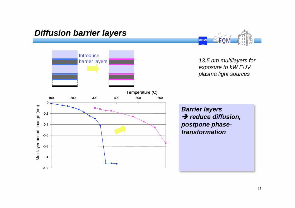
Barrier layers
reduce diffusion,
postpone phase-
transformation
Introduce
barrier layers
-1.2
-1
-0.8
-0.6
-0.4
-0.2
0
100 200 300 400 500 600
Temperature (C)
Multila
yer
period c
hange (
nm
)Diffusion barrier layersDiffusion barrier layers
13.5 nm multilayers for
exposure to kW EUV
plasma light sources
12
FOMFOM
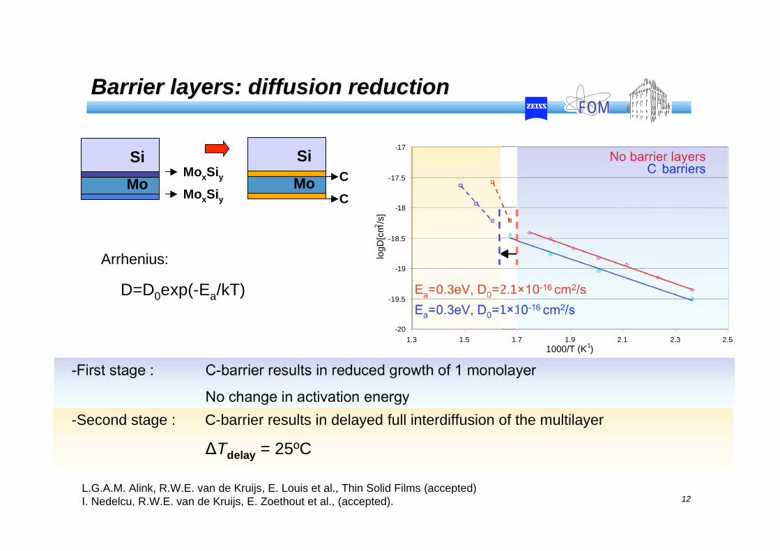
-18.5
-18
-17.5
-17
1.3 1.5 2.3 2.5
logD
[cm
2/s
]
No barrier layersC barriers
1.7 1.9 2.1
1000/T (K-1)
Ea=0.3eV, D0=2.1 10-16 cm2/s
Ea=0.3eV, D0=1 10-16 cm2/s
-20
-19.5
-19
Si MoxSiy
MoxSiyMo
L.G.A.M. Alink, R.W.E. van de Kruijs, E. Louis et al., Thin Solid Films (accepted)
I. Nedelcu, R.W.E. van de Kruijs, E. Zoethout et al., (accepted).
Si
C
CMo
-First stage : C-barrier results in reduced growth of 1 monolayer
No change in activation energy
-Second stage : C-barrier results in delayed full interdiffusion of the multilayer
Tdelay = 25ºC
Barrier layers: diffusion reductionBarrier layers: diffusion reduction
D=D0exp(-Ea/kT)
Arrhenius:

13
FOMFOM
0
5
10
15
20
25
20 40 60 80 100 120 140
= 0.4
(110)
(200)
(211)
(220)(310)
(222)
(321)
Experimental data :
Calculated polycrystalline
cubic Mo diffraction spectrum
(random orientations)
Absolute intensities :
Diffracting volumes
Peak widths :
Crystallite sizes, strain fields
Peak positions :
Lattice structure,
lattice strain
Relative intensities :
Crystallite orientations
Diffraction angle 2 (degrees)
Diffracted
intensity (cps)
WAXRD
Nano-crystallite growthNano-crystallite growth
cos
940
W
.L =Scherrer’s equation:
: x-ray wavelength.
,W : diffraction angle and width.

14
FOMFOM
30
35
40
45
50
55
0 10 20 30 40 50 60 70 80
Lattice angle (degrees)
Cry
sta
llit
e s
ize (
Am
gstr
om
)
30
35
40
45
50
55
0 10 20 30 40 50 60 70 80
Lattice angle (degrees)
Cry
sta
llit
e s
ize (
Am
gstr
om
)
Nano-crystallite growthNano-crystallite growth
30
35
40
45
50
55
0 10 20 30 40 50 60 70 80
Lattice angle (degrees)
Cry
sta
llit
e s
ize (
Am
gstr
om
)
lattice angle (degrees)
L
L
increases
d increasesdMo increases.
dMo
dMo
Columnar crystallite growth.
Transversal size determined by Mo layer thickness.
Mo nucleates on silicide layer:
structure of the silicide determines
structure of Mo

15
FOMFOMProtective capping layersProtective capping layers
13 nm
Spacer (Si)
Reflector (Mo)
Exposure of multilayer to high EUV flux
P = 10 mW/mm2
At (U)HV background gases
H2O ~ 10-6 mbar
CxHy < 10-10 mbar
Cap layer
Stable C capping layer provides effective
protection
Constant reflectivity over 15 hr continued
exposure
C properties critically depend on deposition & EUV
stabilization
0
2
4
6
8
10
0 2 4 6 8 10 12 14 16
Exposure time (hours)
Reflection loss (
%) uncapped
Mo/Si
standard C
stabilized C
Oestreich, Louis, et al; SPIE 4146-07, 2000
Yakshin, Bijkerk,et al, Aset/Sematech Proc. www.sematech.org/docubase, pp. P6-6 (2001)

16
FOMFOMProtective capping layers, C depositionProtective capping layers, C deposition
Without EUV: physisorption of CH at mirror surface
EUV: cracking of molecular bonds, chemisorption
Lifetime criterion: 1 nm C (~1% abs)
C-contamination model Jonkers and Bisschops
S. Oestreich et al; SPIE 4146-07, 2000

17
FOMFOMControl of surface oxidationControl of surface oxidation
Life time expt: 230 h EUV exposure @ PTB
-3.0
-2.0
-1.0
0.0
1.0
2.0
-6.5
-6.0
-5.5
-5.0
-4.5
-4.0
-3.5
-3.0
-2.5
-2.0
-1.5
-1.0
-0.5
0.0
X
Y
66.4 %
66.2 %
66.0 %
65.8 %
65.6 %
65.4 %
65.2 %
65.0 %
estimated position of EUV spot
65.7%
66.4%
Initial reflectance 66.4%Background: CxHy, H2O, O2
Intensities: 30 mW/mm
• No loss of reflectivity
• Surface analysis shows
no oxidation or other damage
• Extrapolation: 1000 hrs lifetime(1% R)
Mo/Si + capping layer:

18
FOMFOMCoating infrastructureCoating infrastructure
Advanced Development Coater
• thermal, medium energy deposition
• plasma & ion surface treatment
Analysis Advanced Development Coater
• XPS, AES, SEM
• Ion-beam surface analysis
• GI- XRR, XRD
substrate
Kaufmann ion source
RF plasma source
thermal energy deposition
magnetrons
in-situ reflectivity
19
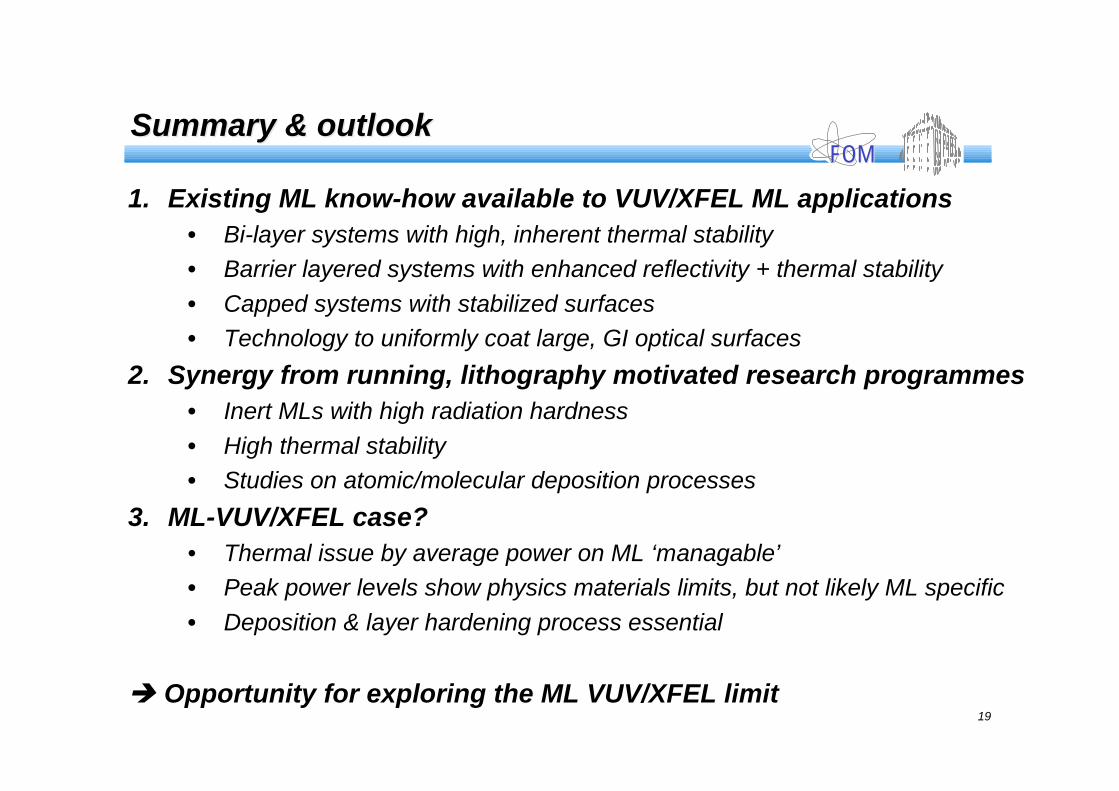
FOMFOMSummary & outlookSummary & outlook
1. Existing ML know-how available to VUV/XFEL ML applications
• Bi-layer systems with high, inherent thermal stability
• Barrier layered systems with enhanced reflectivity + thermal stability
• Capped systems with stabilized surfaces
• Technology to uniformly coat large, GI optical surfaces
2. Synergy from running, lithography motivated research programmes
• Inert MLs with high radiation hardness
• High thermal stability
• Studies on atomic/molecular deposition processes
3. ML-VUV/XFEL case?
• Thermal issue by average power on ML ‘managable’
• Peak power levels show physics materials limits, but not likely ML specific
• Deposition & layer hardening process essential
Opportunity for exploring the ML VUV/XFEL limit