Embed Size (px)
Citation preview

Multilevel Converters for a 10 MW, 100 kV Transformer-less Offshore Wind Generator System
Tor Martin Iversen
Master of Energy and Environmental Engineering
Supervisor: Tore Marvin Undeland, ELKRAFTCo-supervisor: Sverre Skalleberg Gjerde, ELKRAFT
Department of Electric Power Engineering
Submission date: June 2012
Norwegian University of Science and Technology


Problem Description
Title: Multilevel Converters for a 10 MW, 100 kVTransformer-less OffshoreWind Generator System
Background
Offshore wind energy has a large potential, and power ratings in offshore windturbines are reaching for 10 MW. When the turbine size increases, the nacelleweight reduction becomes a key element. A new module-based generator con-cept that omits both the gear box and the transformer, and by that creates alightweight turbine solution, is under development in a PhD-project. The newconcept utilizes a special permanent magnet synchronous generator with nineconverter modules in series to obtain a 100 kV DC voltage output.
The basis for this master thesis is the master specialization project from the fallof 2011, which presents the modular multilevel converter (MMC) as the mostinteresting candidate for the proposed concept. To verify the MMC topologyas a realistic candidate, further studies are required.
Expected outcome of the project:
The work should continue the comparison of the MMC and a conventional two-level converter, with respect to their suitability for the proposed concept. Thelist of criteria includes voltage quality, harmonic content, DC voltage ripple andfilter demands. The simulations performed in the specialization projects weresimplified and ideal. A natural delvelopment of these models should includecontrol challenges revealed in the specialization project, i.e. voltage balancingcontrol and redundancy. The MMC should also be implemented in the full scalesimulation models from the PhD-project.
The student will work with PhD-candidate Sverre S. Gjerde, who will be themain contact person. He started his PhD-work during fall 2009.
Responsible supervisor will be professor Tore Undeland.
iii

iv

Abstract
Multilevel Converters for a 10 MW, 100 kV Transformer-less OffshoreWind Generator System
The size of offshore wind generators is increasing, and the trend is movingtowards full converter gear-less solutions with permanent magnet synchronousgenerators (PMSG). The nacelle weight reduction is a key design criterion foroffshore wind turbines. To overcome the weight challenge, a transformer-lessconcept is under development. This concept employs a special PMSG with aninnovative high insulation level between the groups of windings. The generatorsupplies nine series connected converter modules, which results in a high voltageDC output of 100 kV, reducing the total weight of the system.
Conventional three phase 2-level voltage source converters, each with 11.1 kVoutput, are utilized in concept studies and simulations. However, other volt-age source converter topologies are assumed to be more beneficial in terms ofefficiency, voltage quality and reliability issues. This work compares multilevelconverter topologies with regards to their suitability for the proposed concept.
The result of an initial study is that the modular multilevel converter (MMC)is the most promising candidate. The MMC adds more components and com-plexity to an already intricate system, but gives benefits that are in line withmany of the ideas behind the proposed concept. A modular structure grantsthe easiest expansion to a high number of levels, providing a high-quality volt-age with less demand for filters to save both volume and weight. The MMCalso offers redundancy possibilities for higher reliability, which is important inoffshore wind power installations.
PSCAD/EMTDC simulation models have been built, implementing voltage bal-ancing and redundancy control. The simulations have also investigated thefunctionality of the converter in the proposed system. The results show thatthe MMC performs well in the full system, and is therefore considered as aviable candidate. The number of levels needed is at least five to avoid seriesconnection of IGBTs. Further studies should find an optimal number of levels,depending on the generator specifications, the desired level of losses, voltagequality and a weighting of reliability versus complexity.
v

vi

Sammendrag
Flernivåomformere for et 10 MW, 100 kV transformatorløst offshorevindgeneratorsystem
Ytelsen på vindkraftturbiner er i kontinuerlig vekst, og strekker seg i dag mot10 MW. Trenden viser økt bruk av turbiner designet for variabel hastighet ogpermanentmagnet synkrongeneratorer (PMSG) med fullomformerløsninger. Idesign av store turbiner er nacellevekten avgjørende. Et helt nytt turbinkon-sept er derfor under utvikling ved NTNU. Konseptet benytter en veldig spesiellPMSG og ni seriekoblede omformere, som til sammen gir en DC-spenning på100 kV. En vektreduksjon oppnås ved å unngå både girboks og transformator inacellen.
Konvensjonelle trefaset tonivåomformere er brukt i innledende studier og simu-leringer av systemet med ni omformermoduler. Tonivåomformeren er mye brukti systemer med lavere spenning, men på grunn av det høye spenningsnivået re-sulterer en bruk av tonivåomformere i en seriekobling av transistorer. Dette eruønsket. I tillegg er det grunnlag for å tro at andre omformertopologier harbedre egenskaper innen effektivitet, spenningskvalitet og pålitelighet.
Et forstudie har pekt ut en modulær multinivå omformer (MMC) som det mestinteressante alternativet til konvensjonelle løsninger. MMC gir fordeler som øktspenningskvalitet, redusert filtrering, lavt harmonisk nivå og økt pålitelighet iform av redundans. Denne masteroppgaven omfatter en grundigere studie avMMC-omformeren og dens anvendbarhet i det nye turbinkonseptet. PSCAD-simuleringer er brukt i en grundig sammenligning mot tonivåomformeren, bådei enkeltstående MMC-modeller og i et komplett vindturbinsystem. Utfordringermed spenningsbalansering og redundans har blitt nøye studert.
Resultatene viser at en MMC fungerer veldig godt i det foreslåtte turbinkon-septet, og bedre enn tonivåomformeren med tanke på spenningskvalitet ogpålitelighet. På grunn av spenningsnivået behøves minst 5 nivå. Det optimaleantall nivå avhenger av ønsket grad av redundans, generatorspesifikasjoner ogen optimalisering og veining mellom ønsket spenningskvalitet, tap, vekt, volumog kompleksitet.
vii

viii

Preface
This master’s thesis is the final part of the electrical power engineering masterprogramme at NTNU. Looking back on my first years, I remember thinking ofmaster students as very serious and hard-working, with no spare time for all thefun we as first year students had. And the infamous master thesis! At that timeit seemed so terrifyingly far away, both in time and amount of knowledge. Thismaster’s thesis is therefore a proof of that I’ve made it through these five years,and a symbol of my great gratitude towards NTNU and Trondheim as a studentcity. The work has given me a good background in the field of power electronics,but also provided an important exercise in individual project discipline.
The fact that I find the topic very interesting has raised my motivation andeased the work. I would like to point out some people that have provided greatinspiration and help in the writing of this thesis.
First I would like to thank my co-supervisor Sverre S. Gjerde for all the helpand support in understanding the concept, help with paper-writing and presen-tations, and for being available and patient, despite all my silly questions.
Jon Are Suul has also been very supportive regarding programming and simu-lations in PSCAD. Thanks also to Pål Keim Olsen for explaining the generatorconcept. The other guys in the study room and my fellow master students alldeserve big thanks for all the fun and support during my studies.
Finally, I sincerely thank Professor Tore Undeland, my supervisor. It was be-cause of him and his introduction course in power electronics, that I got inter-ested in this field of power engineering. He has been a true inspiration.
Trondheim, 20th of June 2012
Tor Martin Iversen
ix

x

Contents
1 Introduction 11.1 Background and motivation . . . . . . . . . . . . . . . . . . . . . 1
1.1.1 Offshore wind . . . . . . . . . . . . . . . . . . . . . . . . . 21.2 Relation to the Specialization Project . . . . . . . . . . . . . . . 31.3 Scope of work . . . . . . . . . . . . . . . . . . . . . . . . . . . . . 41.4 Presentations and publication of results . . . . . . . . . . . . . . 5
2 The proposed turbine concept 72.1 The conventional solution . . . . . . . . . . . . . . . . . . . . . . 7
2.1.1 Trend towards permanent magnet machines . . . . . . . . 82.2 The low-weight, high voltage solution . . . . . . . . . . . . . . . . 10
2.2.1 Reduced current . . . . . . . . . . . . . . . . . . . . . . . 112.3 Wind turbine control system . . . . . . . . . . . . . . . . . . . . 11
2.3.1 Operation target . . . . . . . . . . . . . . . . . . . . . . . 112.3.2 Outer controller . . . . . . . . . . . . . . . . . . . . . . . 122.3.3 Current controller . . . . . . . . . . . . . . . . . . . . . . 132.3.4 DQ-transformation to modulation . . . . . . . . . . . . . 13
2.4 DC link and grid . . . . . . . . . . . . . . . . . . . . . . . . . . . 132.5 High voltage insulation . . . . . . . . . . . . . . . . . . . . . . . . 142.6 Converter module . . . . . . . . . . . . . . . . . . . . . . . . . . . 14
3 Voltage Source Converters 173.1 Introduction . . . . . . . . . . . . . . . . . . . . . . . . . . . . . . 173.2 Standard two-level VSC . . . . . . . . . . . . . . . . . . . . . . . 17
3.2.1 The troublesome series connection . . . . . . . . . . . . . 193.3 The multilevel concept . . . . . . . . . . . . . . . . . . . . . . . . 20
3.3.1 Operation principle . . . . . . . . . . . . . . . . . . . . . . 203.3.2 Advantages . . . . . . . . . . . . . . . . . . . . . . . . . . 213.3.3 Possible drawbacks . . . . . . . . . . . . . . . . . . . . . . 22
3.4 Multilevel modulation strategies . . . . . . . . . . . . . . . . . . 223.4.1 Fundamental frequency . . . . . . . . . . . . . . . . . . . 223.4.2 Programmed PWM . . . . . . . . . . . . . . . . . . . . . 233.4.3 Carrier based PWM . . . . . . . . . . . . . . . . . . . . . 24
xi

3.4.4 Space Vector PWM . . . . . . . . . . . . . . . . . . . . . 263.5 Multilevel topologies . . . . . . . . . . . . . . . . . . . . . . . . . 28
3.5.1 Neutral Point Clamped VSC . . . . . . . . . . . . . . . . 283.5.2 Active - Neutral Point Clamped . . . . . . . . . . . . . . 293.5.3 Flying Capacitor Converter . . . . . . . . . . . . . . . . . 303.5.4 Cascaded H-Bridge Converter . . . . . . . . . . . . . . . . 333.5.5 Hexagram Converter . . . . . . . . . . . . . . . . . . . . . 343.5.6 Modular Multilevel Converter . . . . . . . . . . . . . . . . 36
3.6 Comparison . . . . . . . . . . . . . . . . . . . . . . . . . . . . . . 413.6.1 Unsuitable topologies . . . . . . . . . . . . . . . . . . . . 413.6.2 Reliability . . . . . . . . . . . . . . . . . . . . . . . . . . . 413.6.3 Complexity and series connections of IGBTs . . . . . . . . 423.6.4 THD . . . . . . . . . . . . . . . . . . . . . . . . . . . . . . 433.6.5 Power losses . . . . . . . . . . . . . . . . . . . . . . . . . . 433.6.6 Comparison summary and choice of converter topology . 44
4 MMC: A closer look at the most promising candidate 454.1 Introduction . . . . . . . . . . . . . . . . . . . . . . . . . . . . . . 454.2 Redundancy . . . . . . . . . . . . . . . . . . . . . . . . . . . . . . 454.3 Eliminating filters by reducing the harmonic content . . . . . . . 46
4.3.1 Voltage quality standards . . . . . . . . . . . . . . . . . . 464.3.2 The number of levels to avoid filtering . . . . . . . . . . . 47
4.4 The amount of transistors . . . . . . . . . . . . . . . . . . . . . . 474.5 MMC voltage balancing control strategy . . . . . . . . . . . . . . 49
4.5.1 The challenge . . . . . . . . . . . . . . . . . . . . . . . . . 494.5.2 Balancing strategies . . . . . . . . . . . . . . . . . . . . . 504.5.3 Reduction of switching losses . . . . . . . . . . . . . . . . 52
5 Simulations 555.1 Description . . . . . . . . . . . . . . . . . . . . . . . . . . . . . . 55
5.1.1 MMC PSCAD model . . . . . . . . . . . . . . . . . . . . . 555.1.2 MMC capacitor voltage balancing block . . . . . . . . . . 565.1.3 Redundancy in the MMC: An n-1 scenario . . . . . . . . 585.1.4 The full system . . . . . . . . . . . . . . . . . . . . . . . . 60
5.2 Simulation results and analysis . . . . . . . . . . . . . . . . . . . 635.2.1 Single operated MMC converter . . . . . . . . . . . . . . 635.2.2 MMC voltage balancing control algorithm . . . . . . . . . 655.2.3 Redundancy, n-1 scenario . . . . . . . . . . . . . . . . . . 675.2.4 MMC Multilevel arrangement - reducing filtering . . . . . 705.2.5 MMC model in the full system . . . . . . . . . . . . . . . 70
5.3 Discussion . . . . . . . . . . . . . . . . . . . . . . . . . . . . . . . 785.3.1 Performance . . . . . . . . . . . . . . . . . . . . . . . . . 785.3.2 Number of levels . . . . . . . . . . . . . . . . . . . . . . . 78
6 Conclusions 81
xii

7 Further work 83
Appendix A DQ-transformation 93
Appendix B Multilevel simulations: MMC 5-23 levels 97B.1 5 levels . . . . . . . . . . . . . . . . . . . . . . . . . . . . . . . . . 98B.2 7 levels . . . . . . . . . . . . . . . . . . . . . . . . . . . . . . . . . 99B.3 9 levels . . . . . . . . . . . . . . . . . . . . . . . . . . . . . . . . . 100B.4 11 levels . . . . . . . . . . . . . . . . . . . . . . . . . . . . . . . . 101B.5 13 levels . . . . . . . . . . . . . . . . . . . . . . . . . . . . . . . . 102B.6 15 levels . . . . . . . . . . . . . . . . . . . . . . . . . . . . . . . . 103B.7 17 levels . . . . . . . . . . . . . . . . . . . . . . . . . . . . . . . . 104B.8 19 levels . . . . . . . . . . . . . . . . . . . . . . . . . . . . . . . . 105B.9 21 levels . . . . . . . . . . . . . . . . . . . . . . . . . . . . . . . . 106B.10 23 levels . . . . . . . . . . . . . . . . . . . . . . . . . . . . . . . . 107
Appendix C Fortran code: Balancing block 109
Appendix D Technoport RERC Abstract 115
Appendix E EPE Wind Energy and T&D Chapters Seminar Pa-per 119
xiii

xiv

List of Figures
2.1 Standard DFIG structure . . . . . . . . . . . . . . . . . . . . . . 72.2 Standard PMSG structure . . . . . . . . . . . . . . . . . . . . . . 82.3 The proposed generator structure . . . . . . . . . . . . . . . . . . 102.4 Overview of the complete control system for the proposed struc-
ture. Main elements: Voltage controller (outer controller), Cur-rent controller (inner controller) and the modulation block. . . . 12
2.5 A more detailed block diagram of the inner controller of figure2.4. . . . . . . . . . . . . . . . . . . . . . . . . . . . . . . . . . . 13
3.1 Principal drawing of a two-level voltage source converter. . . . . 183.2 The phase voltage Vph and the reference voltage Vcontrol of a two
level converter, controlled with ordinary pulse width modulation 183.3 The principle of series connection of IGBTs in a two-level VSC . 193.4 a) Desired operation: All IGBTs block simultaneously. b) Fail-
ure: Only T4 block VDC . . . . . . . . . . . . . . . . . . . . . . . 193.5 Principal drawing of an n-level converter phase leg . . . . . . . . 213.6 Phase voltages Va and the voltage reference signal in a two level,
five level and a 15 level converter . . . . . . . . . . . . . . . . . . 213.7 Different multilevel modulation strategies [1] . . . . . . . . . . . 223.8 Fundamental Frequency PWM with the one turn-on angle α1 . . 233.9 Selective harmonic elimination with Programmed PWM: Funda-
mental frequency output with one notch added for elimination oftwo harmonic components . . . . . . . . . . . . . . . . . . . . . . 24
3.10 PWM for the five-level NPC, first IGBT . . . . . . . . . . . . . . 253.11 PWM for the five-level NPC, second IGBT . . . . . . . . . . . . 263.12 PWM firing for one of the IGBTs in a two-level converter . . . . 263.13 Space vector diagram: a) 5-level structure [1], b) 2-level SVM . . 273.14 An example of 3rd harmonic injection . . . . . . . . . . . . . . . 283.15 Converter topology - 3 level NPC . . . . . . . . . . . . . . . . . . 293.16 Converter topology - 3 level A-NPC . . . . . . . . . . . . . . . . 303.17 Converter topology - 5 level Flying Capacitor Converter . . . . . 313.18 Two modules of a Cascaded H-Bridge converter topology . . . . . 333.19 CHB-converter used for AC/DC conversion. From [2] . . . . . . . 34
xv

3.20 Topology - Hexagram converter - from [3] . . . . . . . . . . . . . 353.21 Example of a Hexagram rectifier, with isolated DC/DC convert-
ers - from [4] . . . . . . . . . . . . . . . . . . . . . . . . . . . . . 353.22 The MMC: General n-level structure . . . . . . . . . . . . . . . . 363.23 A basic MMC block: The submodule . . . . . . . . . . . . . . . . 373.24 MMC submodule operating state ON. T1 is on while T2 is off . . 383.25 MMC submodule operating state OFF. T1 is off while T2 is on . 383.26 Single phase equivalent circuit of the MMC . . . . . . . . . . . . 393.27 Measured THD in the line-to-line voltage Vab in four converter
topologies . . . . . . . . . . . . . . . . . . . . . . . . . . . . . . . 43
4.1 MMC submodule with external bypass switch . . . . . . . . . . . 464.2 5-level MMC without capacitor voltage balancing - drifting ca-
pacitor voltages . . . . . . . . . . . . . . . . . . . . . . . . . . . . 494.3 5-level MMC without capacitor voltage balancing: The phase
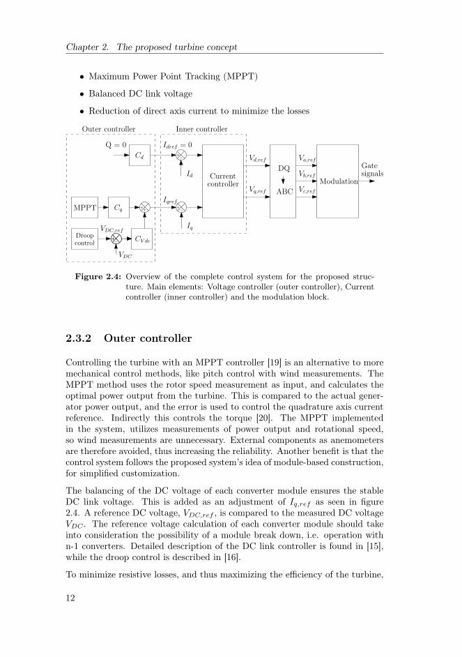
voltage gradually transforms to a three-level voltage. . . . . . . . 494.4 Block diagram of the balancing strategy . . . . . . . . . . . . . . 514.5 Algorithm: capacitor voltage sorting . . . . . . . . . . . . . . . . 52
5.1 Overview of the MMC simulation model connected as a rectifier . 565.2 Fortran-programmed balancing calculation block in PSCAD . . . 575.3 PWM comparator scheme for four submodules . . . . . . . . . . 575.4 PSCAD: Calculation of the desired number of ON-state submod-
ules, nn . . . . . . . . . . . . . . . . . . . . . . . . . . . . . . . . 585.5 Edge detector block used to set a switching instant . . . . . . . . 585.6 Output nn from the comparison block in figure 5.4 . . . . . . . . 595.7 Submodule with breakers for disconnection and bypass . . . . . . 595.8 Reduced PWM comparator with three triangle-signals . . . . . . 605.9 PWM comparator scheme for the bypassed system with three
submodules . . . . . . . . . . . . . . . . . . . . . . . . . . . . . . 605.10 Signal from comparator at the bypassing of submodule 1 . . . . . 615.11 PSCAD model of one machine model and one converter from the
full system . . . . . . . . . . . . . . . . . . . . . . . . . . . . . . . 615.12 Phase voltages Va, Vb and Vc in the separated operation of an
MMC in rectifier mode. . . . . . . . . . . . . . . . . . . . . . . . 645.13 Line currents Ia, Ib and Ic in the separated operation of an MMC
converter in rectifier mode. . . . . . . . . . . . . . . . . . . . . . 645.14 Submodule capacitor voltages VC1 - VC4, phase a, upper arm.
Separated operation of an MMC converter in rectifier mode. . . 645.15 Submodule capacitor voltages in upper arm, phase a: The voltage
balancing control is disabled at t = 0.5 s, resulting in driftingcapacitor voltages. . . . . . . . . . . . . . . . . . . . . . . . . . . 65
5.16 Phase voltage Va, capacitor voltage balancing control disabled att = 0.5 s, resulting in a three-level functionality. . . . . . . . . . 65
5.17 Phase current ia: Before capacitor voltage balancing control isdisabled at 0.4 s. . . . . . . . . . . . . . . . . . . . . . . . . . . . 66
xvi

5.18 Phase current ia: After capacitor voltage balancing control isdisabled, and the phase voltage has developed a three-level form. 66
5.19 Capacitor voltages, upper arm, phase a: Redundancy test at t =0.4 s. The first submodule of phase a is bypassed. . . . . . . . . . 67
5.20 Phase voltages Va, Vb, Vc: Redundancy test: The first submoduleof phase a is bypassed at t = 0.4 s. . . . . . . . . . . . . . . . . . 68
5.21 Line-to-line voltages Vab, Vbc and Vac: Redundancy test: Thefirst submodule of phase a is bypassed at t = 0.4 s. . . . . . . . . 69
5.22 Phase currents Ia, Ib, Ic. Redundancy test: The first submoduleof phase a is bypassed at t = 0.4 s. . . . . . . . . . . . . . . . . . 69
5.23 THD in Vab before and after bypass of submodule 1 in phase a. . 705.24 The reduction in THD in line-line voltage Vab when the number
of levels is increased in MMC models from 5 to 23 levels. . . . . 715.25 Startup sequence of the full system: The rotational speed of gen-
erator 1 and its reference. . . . . . . . . . . . . . . . . . . . . . . 725.26 Full system model with 2-level converters. Phase-to-ground volt-
age Va in all three converters. Ldc = 0 . . . . . . . . . . . . . . . 725.27 Full system model with 2-level converters. Phase-to-ground volt-
ages Va, Vb and Vc in converter 1. Ldc = 0 . . . . . . . . . . . . . 735.28 Full system model with 2-level converters. Line-to-line voltage
Vab in converter 1. Ldc = 0 . . . . . . . . . . . . . . . . . . . . . 735.29 Full system model with MMC converters. Phase voltages Va in
all three converter modules. Ldc = 0 . . . . . . . . . . . . . . . . 745.30 Full system model with MMC converters. Phase voltages Va, Vb
and Vc in converter 1. Ldc = 0 . . . . . . . . . . . . . . . . . . . 745.31 Full system model with MMC converters. Line-to-line voltage
Vab in converter 1. Ldc = 0 . . . . . . . . . . . . . . . . . . . . . 755.32 Full system model with standard 2-level VSC. Line current Ia,
Ib and Ic in the first converter module. . . . . . . . . . . . . . . . 755.33 Full system model with 5-level MMC as converter. Line current
Ia, Ib and Ic in first converter module. . . . . . . . . . . . . . . . 765.34 Converter module voltages and total DC-link voltage in the full
system with two-level converters. . . . . . . . . . . . . . . . . . . 765.35 Converter module voltages and total DC-link voltage in the full
system with five-level MMC. . . . . . . . . . . . . . . . . . . . . 775.36 Submodule capacitor voltages VC1−4 in phase a of the MMC,
upper arm, for the full system. . . . . . . . . . . . . . . . . . . . 77
A.1 General principle of vector control DQ-transformation . . . . . . 93
B.1 Harmonic content in line-line voltage Vab in MMC model with 5levels . . . . . . . . . . . . . . . . . . . . . . . . . . . . . . . . . . 98
B.2 MMC 5-level a) Phase voltage Va b) Phase current Ia . . . . . . 98B.3 Harmonic content in line-line voltage Vab in MMC model with 7
levels . . . . . . . . . . . . . . . . . . . . . . . . . . . . . . . . . . 99B.4 MMC 7-level a) Phase voltage Va b) Phase current Ia . . . . . . 99
xvii

B.5 Harmonic content in line-line voltage Vab in MMC model with 9levels . . . . . . . . . . . . . . . . . . . . . . . . . . . . . . . . . . 100
B.6 MMC 9-level a) Phase voltage Va b) Phase current Ia . . . . . . 100B.7 Harmonic content in line-line voltage Vab in MMC model with 11
levels . . . . . . . . . . . . . . . . . . . . . . . . . . . . . . . . . . 101B.8 MMC 11-level a) Phase voltage Va b) Phase current Ia . . . . . . 101B.9 Harmonic content in line-line voltage Vab in MMC model with 13
levels . . . . . . . . . . . . . . . . . . . . . . . . . . . . . . . . . . 102B.10 MMC 13-level a) Phase voltage Va b) Phase current Ia . . . . . . 102B.11 Harmonic content in line-line voltage Vab in MMC model with 15
levels . . . . . . . . . . . . . . . . . . . . . . . . . . . . . . . . . . 103B.12 MMC 15-level a) Phase voltage Va b) Phase current Ia . . . . . . 103B.13 Harmonic content in line-line voltage Vab in MMC model with 17
levels . . . . . . . . . . . . . . . . . . . . . . . . . . . . . . . . . . 104B.14 MMC 17-level a) Phase voltage Va b) Phase current Ia . . . . . . 104B.15 Harmonic content in line-line voltage Vab in MMC model with 19
levels . . . . . . . . . . . . . . . . . . . . . . . . . . . . . . . . . . 105B.16 MMC 19-level a) Phase voltage Va b) Phase current Ia . . . . . . 105B.17 Harmonic content in line-line voltage Vab in MMC model with 21
levels . . . . . . . . . . . . . . . . . . . . . . . . . . . . . . . . . . 106B.18 MMC 21-level a) Phase voltage Va b) Phase current Ia . . . . . . 106B.19 Harmonic content in line-line voltage Vab in MMC model with 23
levels . . . . . . . . . . . . . . . . . . . . . . . . . . . . . . . . . . 107B.20 MMC 23-level a) Phase voltage Va b) Phase current Ia . . . . . . 107
xviii

List of Tables
1.1 Countries with offshore wind 2010 [5] . . . . . . . . . . . . . . . . 2
2.1 The propoced concept - key specifications . . . . . . . . . . . . . 15
3.1 NPC: Synthesis of 3-level AC phase voltage . . . . . . . . . . . . 293.2 FCC: Synthesis of 5-level AC phase voltage . . . . . . . . . . . . 323.3 Some of today’s MMC projects . . . . . . . . . . . . . . . . . . . 373.4 Summary of topology properties . . . . . . . . . . . . . . . . . . 44
4.1 IEEE Standard 519: Voltage distortion limits [6] . . . . . . . . . 474.2 Number of switching devices in different converter topologies . . 484.3 One of the many switching states for each voltage level in a MMC 50
5.1 Full system - simulation model specifications . . . . . . . . . . . 62
xix

xx

Abbreviations
A-NPC Active Neutral Point Clamped
CHB Cascaded H-Bridge
CSC Current Source Converter
CTL Cascaded Two-Level
DFIG Doubly Fed Induction Generator
DQ Direct, Quadrature
FCC Flying Capacitor Converter
HVDC High Voltage Direct Current
MMC Modular Multilevel Converter
NPC Neutral Point Clamped
PCC Point of Common Coupling
PMSG Permanent Magnet Synchronous Generator
pu Per Unit
PWM Pulse Width Modulation
SHE Selective Harmonic Elimination
SVM Space Vector Modulation
THD Total Harmonic Distortion
VAr Volt Ampere reactive
VSC Voltage Source Converter
xxi

xxii

Chapter 1
Introduction
1.1 Background and motivation
The increasing demand for electricity, combined with the necessity of reducingthe CO2-emissions is one of the greatest challenges of this century. There isa need for green energy, and the worldwide energy sector faces a huge publicresponsibility. A responsibility of not only providing the possibility for continu-ous growth in living standards, but also securing that the growth has a certainsustainability. In addition to a greener utilization of fossil fuels like oil and gas,the use of renewable energy sources will be an important contribution to theenergy mix.
The extraction of oil and gas has also given a positive contribution. It haspushed the technology in most disciplines of engineering. In electrical engineer-ing the main results are increased power handling of electrical drives to providepower to offshore compressors and pumps, and a significant reliability improve-ment of many components. As a consequence of this technology advance in oiland gas, high quality components and systems are developed. These compo-nents are also fit for use in other fields - for instance renewable energy.
The idea of supplying offshore installations from shore is not only politicallydriven as a result of global warming. It also requires a certain willingness tomake it happen. Oil companies made several attempts during the 80’s and 90’s,but it was a demanding political process, and failed due to big footprint [7].The Troll A installation is now fully electrified from shore, being the largest oilplatform in the North Sea this saves CO2-emissions in the range of 100,000 to150,000 tonnes per year [8].
Using renewable energy solutions like offshore wind, would give a green contri-bution to the electrification. One idea is to connect offshore wind farms andoffshore installations.
1

Chapter 1. Introduction
1.1.1 Offshore wind
The world market for wind turbines in general continues with exponentialgrowth, and it experienced another record in the year 2011. The total world-wide capacity of wind power worldwide has become 239 GW, which covers 3 %of the worlds electricity demand [5].
The planning of large-scale onshore wind farms have in many cases met greatopposition, often due to the fact that onshore wind farms results in a significantfootprint. In Norway, large plans have have been delayed or cancelled becauseof political protests and demonstrations.
Offshore wind is a relatively new approach to the generation of green electricity.Moving the electrical power generation offshore gives several benefits, but hasa comprehensive list of challenges. This includes mechanical influence, fatigue,transport and assembly, electrical grid design and maintenance issues due to thescarce availability. As mentioned in section 1.1, several technical advancementsin oil and gas applications have resolved challenges in offshore installations.Offshore wind power has because of this become even more technically andeconomically possible. The use of offshore wind is steadily increasing: 1.2 GWwas installed in 2010, resulting in a worldwide total of 3.1 GW, and a share of1.6 % of the total wind capacity [9].
Table 1.1: Countries with offshore wind 2010 [5]
Pos. Country Capacity [MW] Added 2010 [MW]
1 United Kingdom 1341 6532 Denmark 854 190.43 Netherlands 249 24 Belgium 195 1655 Sweden 164 06 China 123 1007 Germany 108.3 36.38 Finland 30 09 Ireland 25 010 Japan 16 1511 Spain 10 012 Norway 2.3 0
Total 3117.6 1161.7
Table 1.1 shows the twelve countries that have realized offshore wind projects.Noteworthy European offshore projects are Sheringham Shoal (U.K. 315 MW)and the many projects north of Germany; BorWin, DolWin, HelWin. Dog-gerbank (U.K. 9000 MW) is under develeopment. Even though Norway is onthe bottom of the list in table 1.1, the two Norwegian companies Statoil and
2

1.2. Relation to the Specialization Project
Statkraft are involved heavily in both Sheringham Shoal and Doggerbank.
President Dr. He Dexin of the World Wind Energy Association has highlightedsome of his observations [5]:
"Wind power has become - as a low-cost, low-risk and non-pollutingenergy option - a pillar of the energy supply in many countries.These countries have been able to create new industries and hun-dreds of thousands of jobs. Other countries should learn from thisexperience and also set up the right policies."
Dr. Dexin includes a new point for consideration, namely the labour market.This is especially important in developing countries and countries with highunemployment rates. Other benefits of offshore wind generation are:
• The wind is stronger and more stable offshore than onshore because ofthe terrain topology.
• An increase in the average wind speed will give a significant increase inpower [10]: Pwind = 1
2ρAU3.
• Transportation is not dependent of a road network capable of handlinghuge loads as wind turbines are getting heavier. This reduces the ecolog-ical impact, and the footprint is smaller.
• An offshore wind farm is, because of the Earth’s curvature, not visiblefrom shore.
• The audible noise is not that prominent offshore.
The work of this thesis will not focus on the political or economical aspectsof wind energy conversion systems. It is however important to point out thatpolitical support in the development is crucial. Examples of politically generatedsupport is the green certificates [11], or government supported incentives inrenewable energy.
1.2 Relation to the Specialization Project
This master thesis is a continuation from a specialization project, which waswritten during the fall of 2011. The specialization project report was titled"Converter Topologies for Enhanced Performance of Wind Turbine Generators".The span of this thesis grasps much of the same topic as the specializationproject. Some of the material from the project report has therefore been usedin order to form a more independent thesis. The actual sections are listed below.
• Section 2.4: DC Link and DC Grid
• Section 3.3: The Multilevel Concept
• Section 3.5: Multilevel Topologies
3

Chapter 1. Introduction
• Section 3.6: Comparison and Choice of Topology
• Section 3.4: Multilevel Modulation Strategies
Since the focus on this thesis has concentrated on the Modular Multilevel Con-verter (MMC) topology, this material includes much of the literature review onthe other converter topologies. The description of the MMC have been updatedand restructured.
1.3 Scope of work
When a specific converter topology was chosen during the specialization projectfor a more narrow study, some challenges and questions about the topology stillremained. A superior goal for the continuation work of this master thesis hastherefore been to study these challenges in depth. This section presents theselected focus points for the master thesis.
The proposed wind turbine concept presented in Chapter 2 includes a generatortopology with nine series connected converters. The main argument for thistopology is to create a reliable, low weight solution without transformer. Itis worth to notice that the main focus of this work is on one of the convertermodules, and its suitability to the proposed concept.
There is a focus on the control of the converter module. The simulation modelshave therefore been upgraded from those used in the specialization project.Challenges with drifting capacitor voltages are included, and a balancing blockhas been programmed in PSCAD. A redundancy case is also included in thesimulations.
In the specialization project, an implementation of the selected converter topol-ogy into the full system is mentioned as a necessary next step. A full systemsimulation model is therefore included, to see if the MMC performs as expectedin the proposed concept. The full model in PSCAD is limited by the edu-cational licence. The tendencies are still believed to be representative for acomplete simulation model.
The results from this work does not involve laboratory results, but are solelybased on simulations in PSCAD. A consequence of this is the exclusion of losscalculations for comparison against real-life losses. Practical issues regarding de-tailed mechanical support structures is not thoroughly studied. Nor is detailedestimates of weight.
The report is organized as follows. Chapter 2 gives an overview of the proposedconcept. In Chapter 3, the studied voltage source converter (VSC) topologiesare described. A topology is chosen for further study, and a closer look at themost interesting topology is performed in Chapter 4. This gives the basis for
4

1.4. Presentations and publication of results
the simulations described in Chapter 5. Finally, the conclusions and scope offurther work are summarized in Chapter 6 and 7.
1.4 Presentations and publication of results
A presentation of the specialization project, and some of the results from thismaster thesis, was given at the Technoport Renewable Energy Research Con-ference which took place in Trondheim 16-18th of April 2012. The abstract isprinted in the conferences’ book of abstracts [12]. See appendix D.
A paper based on this thesis was accepted for a lecture presentation at the EPEJoint Wind Energy and T&D Chapters Seminar in Aalborg, Denmark 28th and29th of June 2012. The title is the same as this thesis, and the paper hasthe following co-authors: Sverre Skalleberg Gjerde (NTNU) and Tore Undeland(NTNU). The paper will be made available through the IEEE Explore website.See appendix E.
5

Chapter 1. Introduction
6
Chapter 2
The proposed turbine concept
This chapter presents first the conventional wind turbine drive train solution.The intention is to highlight some of the challenges with the conventional designin terms of weight and reliability. A new, lightweight and reliable concept isthen presented.
2.1 The conventional solution
The doubly-fed induction generator (DFIG) is today the most popular gener-ator solution in offshore wind applications, and stands for almost 50 % of alloperational generators [13]. A sketch of the solution is shown in figure 2.1.
DFIG
ACAC AC grid
GEARBOX
Figure 2.1: Standard DFIG structure
The DFIG solution consists of:
• A gear box to step down the rotational speed.
• A doubly fed induction generator.
• A proportionally rated AC/AC converter to control the excitation of themachine
7

Chapter 2. The proposed turbine concept
• A step-up transformer, located either in the nacelle or in the foundationof the turbine.
The gear box has a reputation of being a troublesome component, especiallyin offshore wind turbines where the reliability is very important. In a swedishsurvey on failures in wind turbines between 1997 and 2005, the gear box is oneof the main reasons for wind turbine failures. The gear box was in fact the causefor 20 % of the downtime for a typical turbine [14]. The average repair time fora gear box is said to be 256 hours, but the survey is concentrating on onshoresystems where the availability is much better than offshore. The repair time ofa gear box offshore is therefore believed to be longer. In addition, the gear boxis a large and heavy mechanical unit, which has to be mounted and replaced inone piece. This means that one of few existing crane vessels has to be broughtto the site. The repair time will not only influence large components like thegear-box. Electrical components that are relatively easy to replace manually inonshore turbines, will have a much longer repair-time offshore. The repair timewill also depend on the weather conditions to a larger extent than onshore.
The gear box is therefore one of the reasons why the use of permanent magnetgenerator machines is increasing.
2.1.1 Trend towards permanent magnet machines
The average generator size in offshore wind turbines is increasing, and is today3.8 MW [13]. The main reason for the increase in size, is that it is moreconvenient in terms of infrastructure, transport, assembly and maintenance, touse few large wind turbines instead of many small. The trend in offshore wind isleaning towards a permanent magnet synchronous generator (PMSG) solution[13]. The classical PMSG solution is shown in figure 2.2, and consists of:
• A permanent magnet synchronous generator.
• A full converter back-to-back.
• A step up transformer connected to the grid.
PMSG ACDC
DCAC
AC grid
Figure 2.2: Standard PMSG structure
Using a permanent magnet machine offers some advantages that are very usefulcompared to a DFIG-solution:
8

2.1. The conventional solution
• Direct driven without need for gearing.
• Less maintenance; no brushes nor slip-rings.
• Increased reliability.
• Increased efficiency in the whole range of wind speeds [13].
Firstly, because of the permanent magnet rotor excitation, the number of polescan be much higher than for the induction machine. The greater number ofpoles enables the direct driven low speed operation of the turbine. A gearbox is therefore avoided. Equation 2.1 describes the relationship between thesynchronous rotational speed nsync in RPM, the electrical frequency fe andthe number of poles in the machine. If the electrical frequency is said to beconstant, it is evident from equation 2.1 that the number of poles must increasewhen the rotational speed is decreased.
nsync =120fep
(2.1)
Secondly, the PMSG has no slip-rings nor brushes that needs maintenance.Reducing the need for maintenance increases the time between service, whichis beneficial since the accessibility is much worse offshore than onshore. Inaddition, a comparison in [13] show that both low-speed and medium-speedPMSGs have superior efficiency to the other generator solutions. The efficiencyis also increased over a larger span in wind speeds.
The disadvantages with PMSGs are related to political and environmental is-sues, and the price. China is today the largest exporter of the material NdFeB,and the price is very high. A fair question is therefore; is the reliability advan-tage in gear-less turbine significant enough to justify the price.
If a standard PMSG solution is chosen, the system is more reliable and moreefficient. For larger turbines, it is believed that the weight is reduced withPMSGs. This because the relative weight of a gear box increases more rapidlythan for a permanent magnet generator when the torque and size increases.However, as seen in figure 2.2, the step-up transformer is still included. This isdue to the large power handling of the generator, and the relatively low voltage.The standard industrial voltage of 690 V is low in the megawatt segment. Thisresults in a very high current which needs to be transferred down the tower, seeequation 2.2.
A simple calculation shows the maximal output current from a 10 MW generatorwith conventional 690 V output voltage:
Iac,0.690kV =P√3 · U
=10 MW√3 · 690 V
= 8.4 kA (2.2)
9

Chapter 2. The proposed turbine concept
As seen from equation 2.2, a considerable current has to be transferred, andbulky cables are needed if the transformer is to be mounted in the foundation.This is seldom practical, and therefore the transformer for large offshore turbinesis placed in the nacelle. The use of bulky cables is not just a weight issue. Cablesfrom the nacelle and down have to be flexible enough to handle the yaw controlof the turbine.
The voltage output from the generator should therefore be increased in order toreduce the current, reduce the losses and to omit the transformer in the nacelle.
2.2 The low-weight, high voltage solution
To reduce the nacelle weight, a new generator concept is under development.This is presented in [15], [16], and a sketch of the concept is included in figure2.3. The system consists of a special permanent magnet synchronous generatorwith nine sets of 3-phase windings. Each winding set is electrically separatedfrom the others, and supplies a three phase converter module. Each convertermodule produces an output DC voltage of 11.1 kV, and the stack of modulesare series connected to obtain a desired DC voltage of 100 kV.
PMSG ACDC
ACDC
ACDC
ACDC
ACDC
+
-
DC Link100 kV
ACDC
ACDC
ACDC
ACDC
11.1 kV
Figure 2.3: The proposed generator structure
As seen in figure 2.3, both the gear box and the step up transformer is nowreplaced by a special PMSG- and converter structure. The weight reductionis a direct result of the special solution. Even though the permanent magnetgenerator is large, and the concept introduces many more converters, the totalweight is assumed to be significantly reduced. There are a few arguments forthis:
10

2.3. Wind turbine control system
• The transformer and gear is omitted.
• The generator is built by composite materials instead of cast steel, and istherefore lighter than a corresponding induction machine. The generatormass is typically 20-30 % of the equivalent iron-cored systems [17].
The structure is stripped for two heavy components, and is by that simpler.The converter part seems at first glance more complex, but it is actually notthat intricate - compared to the alternative. Because of component limitationsat the desired power and voltage rating, a single two-level full-converter struc-ture would also need both series- and parallel connections to handle the powerrating. So if a complex structure is unavoidable, the challenge is to make upfor this complexity in a reliable design. This is indeed one of the intentionswith the proposed system [18]. With a more complex system comes more com-plex support structures. A detailed study of weight and size is not included inthis thesis. It is therefore difficult to estimate the details around the structuraldimensioning of the wind turbine.
2.2.1 Reduced current
A simple calculation shows the current reduction achieved when introducing thehigh voltage output from the converter:
Idc,100kV =P
U=
10 MW100 kV
= 100 A (2.3)
As shown, the high DC-voltage results in a considerably lower current, thusreducing the cable size needed and the transmission losses. Smaller cables willalso give a weight reduction, and simpler assembly.
2.3 Wind turbine control system
The aim in power electronic systems is to control the energy transfer fromthe source to the grid. To fully exploit the possibilities in any types of powerelectronics, good control strategies are needed. Types of control strategies arefor instance mechanical control in variable speed turbines, or the balancing ofthe capacitor voltages in an MMC.
This chapter describes the control strategies used in the proposed wind turbinesystem.
2.3.1 Operation target
In the wind turbine system, the control system is constructed with basis on thefollowing:
11
Chapter 2. The proposed turbine concept
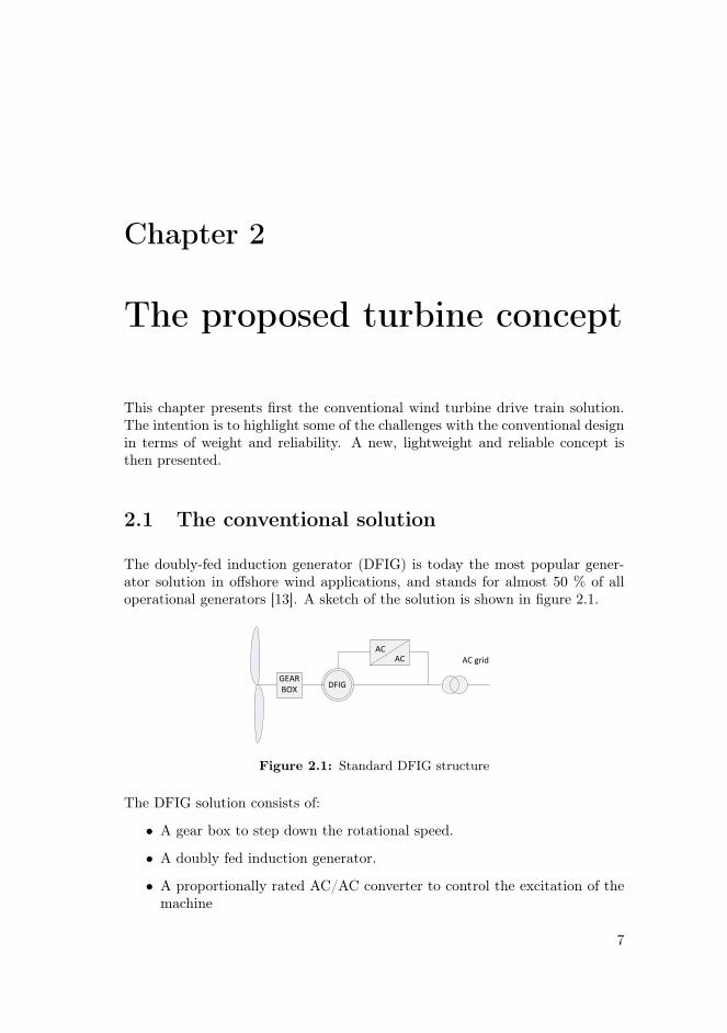
• Maximum Power Point Tracking (MPPT)
• Balanced DC link voltage
• Reduction of direct axis current to minimize the losses
Idref = 0
Id
Iqref
Iq
Currentcontroller
DQ
Vd,ref
Vq,ref
Va,ref
Vb,ref
Vc,ref
Modulation
Gate
ABC
signals
Cd
Cq
Q = 0
Outer controller Inner controller
MPPT
CV dc
VDC,refDroopcontrol
VDC
Figure 2.4: Overview of the complete control system for the proposed struc-ture. Main elements: Voltage controller (outer controller), Currentcontroller (inner controller) and the modulation block.
2.3.2 Outer controller
Controlling the turbine with an MPPT controller [19] is an alternative to moremechanical control methods, like pitch control with wind measurements. TheMPPT method uses the rotor speed measurement as input, and calculates theoptimal power output from the turbine. This is compared to the actual gener-ator power output, and the error is used to control the quadrature axis currentreference. Indirectly this controls the torque [20]. The MPPT implementedin the system, utilizes measurements of power output and rotational speed,so wind measurements are unnecessary. External components as anemometersare therefore avoided, thus increasing the reliability. Another benefit is that thecontrol system follows the proposed system’s idea of module-based construction,for simplified customization.
The balancing of the DC voltage of each converter module ensures the stableDC link voltage. This is added as an adjustment of Iq,ref as seen in figure2.4. A reference DC voltage, VDC,ref , is compared to the measured DC voltageVDC . The reference voltage calculation of each converter module should takeinto consideration the possibility of a module break down, i.e. operation withn-1 converters. Detailed description of the DC link controller is found in [15],while the droop control is described in [16].
To minimize resistive losses, and thus maximizing the efficiency of the turbine,
12

2.4. DC link and grid
the current reduction is preferred. While the q-axis current controls the torque,the d-axis current reference is set to zero to minimize the current [20].
2.3.3 Current controller
The inner controller uses a conventional vector control principle with PI-controllers,which is extensively covered in literature [21], [22]. Figure 2.5 shows the innercontroller, the current controller.
Id,ref
Id
Iq,ref
Iq
PI
PI
ωL
ωL
Vd,ref
Vq,ref
Figure 2.5: A more detailed block diagram of the inner controller of figure 2.4.
The tuning of inner PI current controllers follows the criterion of modulus op-timum, as described in [23].
2.3.4 DQ-transformation to modulation
The inner controller gives the voltage reference signal referred to rotating directand quadrature axes. This signal has to be transformed into a,b and c phasevalues before fed into the modulation block.
A principal description and derivation of DQ-transformation can be found inAppendix A.
The modulation block in figure 2.4, represents the last control operation inthe converter. The input from the current controller is the reference voltage,Vabc,ref . The block can employ different modulation strategies, calculating thegate signals for the switches in the converter. Different modulation strategiesare described in 3.4.
2.4 DC link and grid
HVDC transmission systems are increasing in popularity, and advanced con-verter technology is today included in long distance cable systems both onshoreand offshore. The conventional connection to offshore wind farms is done with
13

Chapter 2. The proposed turbine concept
AC, which is unproblematic when the wind farm is close to shore, and rela-tively small in size. In [24], the different challenges in connecting an offshorewind farm to shore are highlighted. With an increasing size and distance fromshore, a DC connection is not only preferable but also necessary. The ratingof AC-cables is limited, and Static VAr-compensation is needed both offshoreand onshore. A converter station is then placed in the wind farm; normallyconnecting multiple AC feeds from the wind turbines, with a DC connection toshore.
A complete DC grid is also possible, and it is discussed whether a "DC super-grid" can be built or not. There are many challenges regarding DC breakersand fault handling, and the cost of such an offshore network would be enormous[24]. Since the proposed concept supplies a HVDC output, the converter sta-tion platform could be avoided, and the turbine directly integrated in a HVDCsupergrid. A cost reduction is therefore possible, as the converter station isexpensive.
The lack of DC-breakers has been a real argument against the DC grid. ABBclaims the existence of DC breaker technology [25]. This is an indication of thatthe DC breaker might be commercially available in the future.
2.5 High voltage insulation
One of the challenges in many high voltage designs, and also this concept, is theelectric insulation. This applies for both the generator and in every module. Ahigh voltage difference between either the windings and ground, or one moduleand ground requires a good insulation to prevent breakdown. One benefit withthis insulation screen is the size-reduction of the generator because of increasedbreakdown strength. The insulation system of the generator is described in [26].
Insulation design is not included in the scope of this work, but it is an importantissue which needs further research - and therefore mentioned.
2.6 Converter module
The focus of this work is as mentioned in section 1.3, on one converter modulein the proposed structure shown in figure 2.3. A standard two level VSC isutilized in preliminary studies, but this topology suffer from relatively poorvoltage quality and a high capacitor volume. It does not include redundancypossibilities, so the reliability depends upon a well known and proven topology.Series connection of transistors is also necessary because of the high DC-voltagelink.
14

2.6. Converter module
Table 2.1 shows the most important specifications for one of the converter mod-ules.
Table 2.1: The propoced concept - key specifications
Rated total generator power 10 MWRated converter module power 1.1 MW# 3 phase moules 9Converter rated voltage 11.1 kVTotal DC link voltage 100 kVGenerator insulation ±50 kVConverter module insulation ±50 kV
Multilevel converter topologies could be a good alternative in this concept. Theycan provide an increased voltage quality, redundancy possibilities, less filteringand distributed capacitors.
With a great number of AC/DC converters in series, the voltage quality of theDC link is highly affected by the DC voltage quality in each converter. Thereis however a benefit of this. The ripple in the DC-link can be smoothed byshifting the voltage conversion between each of the converter modules in thestack. Since this work focuses on one converter module instead of the wholestructure, this is not further discussed.
If a multilevel converter topology is to be a serious alternative to the conven-tional two-level converter, it must satisfy the following criteria:
• No series connection of IGBTs.
• High voltage quality, low harmonic distortion.
• High reliability, redundancy possibilities.
• Reduced DC-link capacity.
• Preserve the total generator-converter system responce.
15

Chapter 2. The proposed turbine concept
16

Chapter 3
Voltage Source Converters
3.1 Introduction
The use of Voltage Source Converters (VSC) is the state-of-the-art methodof converting and transmitting electrical power. Traditionally, Current SourceConverters (CSC) were preferred in HVDC transmission because of lower lossesand higher transmission capabilities. But due to recent advancements in com-ponent design, VSCs are now used in numerous power electronic applications,and give several benefits. Some of these are:
• Easier bidirectional power flow
• Faster responce because of active switches (IGBTs)
• Better control of active and reactive power
This chapter describes first the standard two-level VSC before introducing theconcept of multilevel converters in section 3.3. A study of the most popularmultilevel topologies is presented in section 3.5. A comparison, and a choice ofconverter topology for further study is summarized in section 3.6.
3.2 Standard two-level VSC
The standard two-level VSC is the baseline converter, and is widely used innumerous applications. It has the simplest structure of the three-phase con-verters, and consists of six IGBTs with diodes in anti-parallel. Figure 3.1 showsthe basic structure of such a two-level VSC. As illustrated in the figure, theDC-link is split in two with capacitors to form a neutral point.
17

Chapter 3. Voltage Source Converters
D1T1
D4T4
D2T2 D3T3
D5T5 D6T6
VDC
+
-
Vac
C
C
Figure 3.1: Principal drawing of a two-level voltage source converter.
By using active switches like IGBTs, both the turn-on and turn-off can becontrolled. The benefit with active switching is the possibility to control bothvoltage phase and amplitude. This is preferred in contrast to thyristor turn-on-based converters, where only one commutation per period is possible. Thephase voltage waveform switches between the two voltage levels V and -V, asshown in figure 3.2.
0.1 0.105 0.11 0.115 0.12 0.125
−1
−0.5
0
0.5
1
Time [s]
Voltage [pu]
Vcontrol
Vph
Figure 3.2: The phase voltage Vph and the reference voltage Vcontrol of a twolevel converter, controlled with ordinary pulse width modulation
Different modulation techniques can be applied, but the carrier-based pulsewidth modulation (CB-PWM) is a common technique and is therefore used inthe simulations presented in this work. To make the converter operate in all fourquadrants, the PWM control signal’s amplitude and the phase-shift in relationto the AC voltage is regulated [27].
The standard two-level VSC benefits with its simplicity, both in structure andcontrol, and is a well-known technology. For low voltage and power ratings itis therefore very popular.
18

3.2. Standard two-level VSC
3.2.1 The troublesome series connection
With higher voltage and power ratings however, each phase arm has to with-stand both a high voltage and a high current. Since each IGBT has limitationsin voltage blocking and current leading capabilities [28], the following two re-quirements may be important:
• Series connection of IGBTs to meet the increased voltage stress on eachswitch.
• Parallel connection of IGBT branches to increase the current leading ca-pability of the converter.
D1T1
D4T4
D2T2 D3T3
D5T5 D6T6
VDC
+
-
Figure 3.3: The principle of series connection of IGBTs in a two-level VSC
VDC
+
-
T1
T2
T3
T4
T5
(a)
T1
T2
T3
T4
T5
VDC
+
-
(b)
Figure 3.4: a) Desired operation: All IGBTs block simultaneously. b) Failure:Only T4 block VDC
The two level converter has been used in high voltage transmissions, but thenwith series connection of switches as shown in figure 3.3. In this figure, each
19

Chapter 3. Voltage Source Converters
switch really consists of five IGBTs in series. IGBTs are available with blockingvoltages up to 6.5 kV [28]. A vital criteria with series connection of IGBTs isthe switch control. The switches have to be turned on or off at the exact sametime to avoid IGBT failure.
Figure 3.4 illustrates the switch failure when the timing is not precise. In 3.4a)all five IGBTs block the voltage simultaneously. The voltage imposed on eachof them is one fifth of the DC voltage, which is lower than their voltage rating.3.4b) illustrates the case of a lag in the turn-off time for one of the IGBTs. T4 isthe only IGBT blocking the whole DC voltage. In series connection of IGBTs,the voltage rating of each switch is lower than the DC voltage, so the IGBTswill most probably short circuit - causing a breakdown of the converter.
The branch of IGBTs has to be able to switch simultaneously. This is how-ever quite complicated, and the consequence of delayed switching in one partof the branch is severe. This is one of the reasons why multilevel convertershave become popular. Another reason is the demand for filtering in two-levelconverters. This is a consequence from the high harmonic content of the phasevoltage shown in figure 3.2.
3.3 The multilevel concept
A patent search done in [29], states that the first multilevel converter waspatented as early as in 1975. This multilevel converter was a cascade in-verter, and connected multiple converter cells in series to form the familiarstaircase voltage waveform. The technology in multilevel converters has sincethen evolved over nearly 40 years, and multilevel converters are now the state-of-the-art solution for medium voltage level applications.
This chapter describes the idea behind multilevel converters, and specially whyit is suitable for the proposed wind turbine concept described in Chapter 2.
3.3.1 Operation principle
Figure 3.5 shows a principle sketch of one leg in a three phase multilevel con-verter. The idea is to stack n-1 capacitors or voltage levels, and use controlledswitching to obtain a desired n-level AC voltage. The amplitude of the voltageis then determined by the number of contributing capacitors [1].
Figure 3.6 compares the typical phase voltage shape of the two-level converterwith multilevel converters. The upper graph shows the two-level phase voltage.This is an unfiltered voltage, switching between two levels. By introducingmore levels, the phase voltage becomes more sinusoidal, and follows the voltagereference, normally a pure sinusoidal wave, more closely. The last graph offigure 3.6 illustrates this, with a 15 level phase voltage. The need for filtering
20

3.3. The multilevel concept
C1
C2
Cn−1
Vac
VDC
+
-
+
-
Figure 3.5: Principal drawing of an n-level converter phase leg
is greatly reduced, and the dvdt is much lower than for the two-level voltage. A
low dvdt is beneficial for generator design, and especially the turn insulation.
−5
0
5
−5
0
5
Phase v
oltage [kV
]
0.105 0.11 0.115 0.12 0.125 0.13
−5
0
5
Time [s]
15 levels
2 levels
5 levels
Figure 3.6: Phase voltages Va and the voltage reference signal in a two level,five level and a 15 level converter
3.3.2 Advantages
Some of the advantages with multilevel converters are:
• The multilevel approach divides the total voltage into multiple levels,which results in a lower dv
dt .
• The losses in a converter include mainly conduction losses and switchinglosses [30]. Reduced switching frequency results in lower switching losses.
21

Chapter 3. Voltage Source Converters
• The harmonic distortion is reduced, resulting in lower loss due to harmoniccomponents.
• Some multilevel topologies make redundancy possibilities easier to imple-ment. This makes component failures less critical for the operation of theconverter.
• The filtering demand in multilevel configurations is reduced, reducing thevolume and cost, and the losses due to filtering.
3.3.3 Possible drawbacks
• The investment cost increases with more complex structures and addi-tional research and development.
• An increase in complexity could jeopardize the reliability.
• Extensive control strategies are needed. For instance, capacitor voltagebalancing strategies are needed for most multilevel converters.
3.4 Multilevel modulation strategies
This section gives a short review of the different modulation strategies used inmultilevel converters. The modulation strategies are divided into synchronousand asynchronous modulation strategies, as indicated in figure 3.7 below.
FundamentalFrequency
ProgrammedPWM
Space VectorPWM
Carrier BasedPWM
Synchronous Asynchronous
Multilevel Modulation Strategies
Figure 3.7: Different multilevel modulation strategies [1]
3.4.1 Fundamental frequency
As the title implies, Fundamental Frequency modulation is a slow switchingmodulation, i.e. synchronized with the reference voltage frequency. There isonly one commutation per cycle. It is used for slow switching semiconductorssuch as gate turn-off thyristors (GTOs) [1].
22

3.4. Multilevel modulation strategies
The fundamental frequency modulation is appropriate for controlling multilevelconverters, and because of half-wave symmetry only 1
2 (n− 1) firing angles haveto be calculated for an n-level converter.
Since there is only one commutation per cycle, this modulation method intro-duces odd, harmonic components. The kth harmonic of an n-level phase voltageis given by [31]:
Fk =4
πk
UDC2
2
n− 1
m∑i=1
cos(kαi) (3.1)
In [31], an optimization algorithm is presented. It is an optimization of harmonicelimination, where the firing angles that results in the lowest harmonic contentare calculated. These m firing angles have to be calculated for each modulationindex mf . Figure 3.8 shows the typical phase voltage in a three level converter,with the turn-on firing angle α1. Because of symmetry, the turn-off angle isπ − α1.
0 1 2 3 4 5 6
−1
−0.5
0
0.5
1
Angle [rad]
Ph
ase
vo
lta
ge
[p
u]
α1
Figure 3.8: Fundamental Frequency PWM with the one turn-on angle α1
3.4.2 Programmed PWM
The Programmed PWM technique is a more advanced fundamental frequencymodulation, and is also called Selective Harmonic Elimination (SHE) [32]. Thestrategy is to eliminate more harmonic components by introducing additionalnotches between the turn-on and the turn-off angle mentioned in section 3.4.1.Each notch is specially designed to eliminate desired harmonic components, oneharmonic component for each notch angle. The higher amount of angles, themore the voltage shape resembles a classical PWM pattern.
In figure 3.9 the addition of one notch is shown. The notch width and positionis calculated in an optimization process to reduce the harmonic components.In the example from figure 3.9, three angles needs to be calculated: the funda-mental turn-on angle α1, and the two angles for the notch, α2 and α3. From
23

Chapter 3. Voltage Source Converters
Fourier-analysis, the three non-linear equations that needs to be solved are [32]:
cos(α1)− cos(α2) + cos(α3) =4
πma (3.2)
cos(5α1)− cos(5α2) + cos(5α3) = 0 (3.3)cos(7α1)− cos(7α2) + cos(7α3) = 0 (3.4)
Where ma is the modulation index. The angles are therefore dependent on themodulation index of the reference voltage signal. Here, the fifth and seventhharmonic components will be eliminated. The third harmonic is not includedbecause of natural elimination in symmetric three phase systems.
Programmed PWM is a very effective way to reduce harmonic components whenapplying a low switching frequency. The number of switching operations isminimized to exactly the number needed for the desired harmonic elimination.In this way, the switching losses are minimized. A possible downside is thelarge data capacity needed to recalculate all the angles for each operating state,especially during transient states. Furthermore, the switching losses increasewith the increasing number of notches created.
0 1 2 3 4 5 6
−1
−0.5
0
0.5
1
Angle [rad]
Ph
ase
vo
lta
ge
[p
u]
α2
α3
Figure 3.9: Selective harmonic elimination with Programmed PWM: Funda-mental frequency output with one notch added for elimination oftwo harmonic components
3.4.3 Carrier based PWM
The classical carrier-based PWM is a widely used modulation technique, andit is used for both classical VSCs and for multilevel converters. In addition tothe technique described in the following, two other carrier based variations aresawtooth rotation and phase shifted carriers. These multicarrier techniques aredescribed in [33].
Figures 3.10 and 3.11 below show the modulation schemes for the two uppermostIGBTs in a phase of a five-level model simulated in PSCAD. With an n level
24

3.4. Multilevel modulation strategies
converter, n − 1 triangle carriers are stacked from -1 to 1. The control signalfor each phase, defined in equation 3.6, is then compared with all the trianglecarriers, with the following criteria:
T1 =
1 if Vcontrol ≥ Vtri0 if Vcontrol < Vtri
(3.5)
Vcontrol,i =
masin(ωt)masin(ωt− 2π
3 )masin(ωt+ 2π
3 )for i = a, b, c (3.6)
Only one of the four carrier signals is shown in the figure, and the switching ofT1+ is marked in blue. The green graph is the a phase control signal with amodulation ratio ma = 0.8.
0.1 0.105 0.11 0.115 0.12 0.125 0.13−1
−0.5
0
0.5
1
Time [s]
PW
M
Vtri1
T1
Vcontrol
Figure 3.10: PWM for the five-level NPC, first IGBT
Figure 3.11 shows the switching signal for the second IGBT. It can be observedthat the first IGBT switches more often, thus having larger switching losses.
25

Chapter 3. Voltage Source Converters
0.1 0.105 0.11 0.115 0.12 0.125 0.13−1
−0.5
0
0.5
1
Time [s]
PW
M
Vtri2
Vcontrol
T2
Figure 3.11: PWM for the five-level NPC, second IGBT
For a two level converter this is similar, but simpler. Figure 3.12 shows thetwo level PWM scheme. The modulation is done by comparing one sinusoidalcontrol signal Vcontrol, which has the same frequency as the system, with atriangle signal, Vtri. The gate trigger signal on the upper IGBT is then oppositeof the gate trigger signal on the lower IGBT [27].
0.1 0.105 0.11 0.115 0.12 0.125 0.13−1
0
1
PW
M
0.1 0.105 0.11 0.115 0.12 0.125 0.13
0
0.5
1
Time [s]
IGB
T F
irin
g S
ign
al
Vcontrol
Vtri
Vgate
Figure 3.12: PWM firing for one of the IGBTs in a two-level converter
3.4.4 Space Vector PWM
The space vector modulation (SVM) technique was presented in the 1980s asan alternative to the classical PWM [1]. The SVM is used to determine theswitching pulse widths, and has become very popular in the last years, muchbecause of the digital implementation in today’s control systems [1].
For an n-level converter there are n3 switching combinations, resulting in 8combinations for a 2-level converter. Two of these combinations short-circuits
26

3.4. Multilevel modulation strategies
the AC side of the converter, and are therefore called zero-states. The sixother are defined as stationary vectors, and any arbitrary output vector can besynthesized from the stationary vectors ~SV1 - ~SV6. A space vector diagram fora two-level modulation is shown in figure 3.13. For a three level converter thenumber of space vectors is 27.
(a)
SV1
SV2SV3
SV4
SV5 SV6
d axis
q axis
SV0 - SV7
ωt
(b)
Figure 3.13: Space vector diagram: a) 5-level structure [1], b) 2-level SVM
Since each switching state corresponds to a space vector, the desired output iscontrolled by the duty cycle for each space vector [31].
Third harmonic injection
An injection of a third harmonic component to the control signal in the PWMmodulation, reduces the peak of the control signal by 15%. This gives theadvantage of an increased modulation region, and thereby a larger control-region. Because of the elimination of 3rd harmonic multiples, this does notaffect the voltage output.
Figure 3.14 shows the injection of a third harmonic with an amplitude of onesixth of the control signal. From the figure it can be observed that an increaseof 15% is possible.
The space vector modulation results in the same utilization improvement as thethird harmonic injection in CBPWM. In [31], it is shown that the modulationindex in SVPWM can be increased by 2√
3compared with the CBPWM, thus
increasing the DC-link utilization by 15%.
27

Chapter 3. Voltage Source Converters
0.16 0.165 0.17 0.175 0.18 0.185 0.19 0.195 0.2−1.5
−1
−0.5
0
0.5
11.15
1.5
Time [s]
Voltage [pu]
V1
V3
Vres
Figure 3.14: An example of 3rd harmonic injection
3.5 Multilevel topologies
A literature review was performed to find actual multilevel alternatives to thetwo-level converter. This chapter describes today’s most popular topologies. Achoise is made for which converter topology to include in the more thoroughstudies and simulations.
3.5.1 Neutral Point Clamped VSC
The diode clamped converter was derived as a manipulation of a cascaded mul-tilevel converter by Nabae et. al. in 1981 [34].
The topology is shown in figure 3.15, and has been called Neutral-Point Clamped(NPC) converter because of the diodes connecting the point between each IGBTto the DC-link neutral point.
In comparison to the two-level VSC, this three-level topology mainly adds onecomponent: the clamping diode. The DC-link voltage is then divided betweenthe switches, thus doubling the obtainable voltage level with the same typeof IGBTs, compared to the two-level VSC. Because of this, the 3-level NPCprevailed in the 1980’s and is today’s state-of-the-art converter for mediumvoltage levels [29].
The switching combinations used to synthesise an AC phase is shown in table3.1. From the topology in figure 3.1, it can be observed that if 1
2Vdc is imposedacross the upper DC link capacitor, an activation of switch Tr1+ and Tr2+ willresult in an AC output voltage on of 1
2Vdc.
The NPC has been extended to a higher number of levels, as in [35] where a5-level topology is described. In [36] a five level NPC is controlled and balancedfor use in a STATCOM1. Because of the increase in complexity when going fromthree to five levels, this five-level topology has not been that popular. Both the
1A STATCOM is a VAr controller that provides instantaneous reactive compensation inutility grids [27].
28

3.5. Multilevel topologies
C2
DC link
C1Tr1+
Tr2+
Tr1-
Tr2-
Ts1+
Ts2+
Ts1-
Ts2-
Tt1+
Tt2+
Tt1-
Tt2-
r
s
t
Figure 3.15: Converter topology - 3 level NPC
Table 3.1: NPC: Synthesis of 3-level AC phase voltage
Phase voltage Switching CombinationsVan Tr1+ Tr2+ Tr1− Tr2−
+ 12Vdc 1 1 - -
0 - 1 1 -
− 12Vdc - - 1 1
increased number of components; switches, diodes and the structural size and amore advanced control system makes the topology more complex. In contrast tomodular converters described later, the complexity is not linear to the numberof levels added. Voltage balancing issues have also been mentioned as the maincause.
3.5.2 Active - Neutral Point Clamped
The Active-NPC converter was first described by T. Brückner and S. Bernet in2001, as a way to balance the losses in a three level NPC [37]. It introducesa small change in the NPC topology described in 3.5.1; the clamping is doneactively by using active components, in this case with IGBTs instead of diodes.
An ordinary NPC has unequally distributed switching losses. The rating of the
29

Chapter 3. Voltage Source Converters
whole converter is then determined by the mostly stressed component. Thisgives an improvement potential in terms of power handling. The additionalswitches make it possible to further control the commutations in the converter,consequently increasing the rating. For larger converters the IGBTs and diodesare water-cooled. In case of large losses, the downside is bulky cooling systemsand therefore a less compact system. The commutations in an A-NPC converterare controlled with feedback from temperature sensors in such a way that theresulting switching losses are equally distributed, and therefore minimized.
Power Source Ls
DC link
Tr1+
Tr2+
Tr1-
Tr2-
Ts1+
Ts2+
Ts1-
Ts2-
Tt1+
Tt2+
Tt1-
Tt2-
Figure 3.16: Converter topology - 3 level A-NPC
Simulations done in [37] show that implementing the active-loss balancing sys-tem improve the total power handling by 20%. This does not reduce the totallosses in the converter, but equally distributes the losses. Alternatively, theswitching frequency could be increased from 1050Hz to 1950Hz, an increase of85%. The trade-off is a more complex topology, i.e. an increased componentcost.
3.5.3 Flying Capacitor Converter
The flying capacitor converter (FCC) was introduced in 1992 [38]. Clamp-ing capacitors instead of diodes gives a more flexible topology where multipleswitching combinations result in the same voltage levels [1].
Figure 3.17 shows the Flying Capacitor topology for a 5-level structure. If eachcapacitor handles the same voltage level, an n-level converter consists of 2(n−1)
30

3.5. Multilevel topologies
switches, (n− 1)(n− 2)/2 clamping capacitors and (n− 1) main DC capacitors[1]. The number of clamping capacitors in series illustrate the charged voltageon each clamping leg [29]. This means that if the total DC link voltage is Vdc,the capacitors C4 are charged with a voltage 1
4Vdc. Since all the capacitors havethe same voltage rating, the voltage in all the other capacitors in the figure is:VC1,C2,C3
= 14Vdc.
T2+
T3+
T4+
T1-
T2-
T3-
C1
C2
C2
C3
C3
DC linka
T4-
T1+
C3
C4
C4
C4
C4
n
Figure 3.17: Converter topology - 5 level Flying Capacitor Converter
To illuminate the flexibility in terms of switching combinations compared withthe NPC, all switching combinations of a 5-level phase leg are shown in table3.2 below2. The switches are not complementary pairs in the FCC topology, soT1+ and T1− can be switched on simultaneously. The table shows that threecombinations exists for 1
4Vdc and − 14Vdc, six for 0 V and one combination for
both 12Vdc and − 1
2Vdc.
For clarification, some voltage combinations are explained in detail.
2A similar table is presented in [1], but the structure presented does not include a groundedneutral point as shown in figure 3.17. The switching combinations are therefore different, andthe combinations presented in table 3.2 have been derived from the structure in figure 3.17.
31

Chapter 3. Voltage Source Converters
12Vdc: If all four of the upper switches are turned on, the path from the neutral
point n to a, includes the voltage 12Vdc from the upper two C4-capacitors.
The C4-capacitors are now in discharging mode.
14Vdc(c): If switches T1+, T3+, T4+ and T3− are turned on, the phase output Van
will be the sum of; 12Vdc (from the upper two C4-capacitors) - 3
4Vdc (fromcapacitors C3), + 1
2Vdc (from capacitors C2). In this case the capacitorsC4 and C2 are in discharging mode, and the capacitors C3 are in chargingmode.
− 14Vdc(b): If the switches T4+, T2−, T3−, T4− are turned on, the phase output Van
will be the sum of; 14Vdc (from C1) - 1
2Vdc (from lower C4’s). In this casethe C4’s are in charging mode, and C1 is in discharging mode.
0(c): Van = 12Vdc (from upper C4’s) - 3
4Vdc (from C3’s) + 12Vdc (from C2’s) -
14Vdc (from C1). In this case the C4’s and C2’s are in discharging mode,while the C2’s and C1 are in charging mode.
Table 3.2: FCC: Synthesis of 5-level AC phase voltage
Phase voltage Switching CombinationsVan T1+ T2+ T3+ T4+ T1− T2− T3− T4−
12Vdc 1 1 1 1 - - - -
14Vdc
1 1 1 - 1 - - -- 1 1 1 - - - 11 1 1 - - 1 -
0
1 1 - - 1 1 - -- - 1 1 - - 1 11 - 1 - 1 - 1 -1 - - 1 - 1 1 -- 1 - 1 - 1 - 1- 1 1 - 1 - - 1
− 14Vdc
1 - - - 1 1 1 -- - - 1 - 1 1 1- - 1 - 1 - 1 1
− 12Vdc - - - - 1 1 1 1
The clamping capacitor voltages must be maintained at a specified level if theconverter is to operate as intended. This means that the charging and discharg-ing of the capacitors have to monitored and controlled to maintain a constantcapacitor voltage. This is however quite complicated, and many FCC config-urations have challenges with floating capacitor voltages [1]. In [38], a controlstrategy that regulates the capacitor voltages for a multilevel flying capacitor
32

3.5. Multilevel topologies
converter is presented. The method has been demonstrated to work in simula-tions with inverters up to nine-levels.
In [39], a new flying capacitor topology is presented, where a modular multilevelmixture is introduced. Advantages in the modular multilevel converter (MMC)are utilized, solving some of the problems with the flying capacitor converter.The modification allows the FCC to be extended to any practical number oflevels without any capacitor voltage balancing problems. A disadvantage com-pared to the MMC, presented in section 3.5.6, is increased conversion losses.
3.5.4 Cascaded H-Bridge Converter
The Cascaded H-Bridge converter (CHB) is a modular converter, and consistsof several blocks of H-bridge cells in series. Each H-bridge block is constructedwith two pairs of switches with diodes in anti-parallel. In figure 3.18, two ofthese cells are connected, showing the phase structure in a CHB converter. Byusing n H-bridge cells, Van is synthesised using 2n− 1 voltage levels [2].
Each module in this configuration needs a separate DC-power output, or for theinverter operation; separate DC sources. The converter’s applications are there-fore somewhat limited. This topology with separate DC sources is instead wellsuited for renewable energy sources such as photovoltaic banks, where many sep-arate sources are available. It has also been applied to wind energy conversion,where concentrated generator windings supply rectifier units to get separatedDC sources.
T1
T1-
T2
T2-
T1
T1-
T2
T2-
C1
C2
Figure 3.18: Two modules of a Cascaded H-Bridge converter topology
For the proposed structure however, this topology does not fit very well becauseof the need for separate DC outputs. One separated DC output is generated foreach H-bridge cell. In order to achieve a combined DC link these outputs mustbe series connected. As shown in figure 3.19, this is not that straight forward.
33

Chapter 3. Voltage Source Converters
Figure 3.19: CHB-converter used for AC/DC conversion. From [2]
One solution is to use isolated DC/DC converters for each H-bridge cell. Thistopology is shown in figure 3.19. The component count increases considerably,reducing the reliability. There is however a possibility of adding redundancy tothe structure. If a fault occurs in one of the H-bridge cells, it can be includedin the control that the faulty cell is short-circuited and the structure continueswith n− 1 cells.
3.5.5 Hexagram Converter
Figure 3.20 shows the basic topology of the Hexagram converter, described byK. Smedley in 2008 [3]. The converter utilizes six full bridge converter modules,similar to the CHB described in the previous chapter. The hexagram converteris used in STATCOMs for reactive compensation, and in medium voltage motordrives.
Advantages from the Hexagram converter are a modular structure, no voltageunbalance problems, straight forward control and low-voltage stress comparedto the 2-level VSC [3].
34

3.5. Multilevel topologies
Figure 3.20: Topology - Hexagram converter - from [3]
Figure 3.21: Example of a Hexagram rectifier, with isolated DC/DC converters- from [4]
In [4] the Hexagram converter is compared to the cascaded H-bridge, and pre-sented as a competitive candidate because of lower component count and loweredenergy storage.
A disadvantage with the hexagram converter is the need for many inductorsto suppress circulating currents [4]. To apply the hexagram converter as arectifier unit supplying a high voltage DC link, each VSC block has to be seriesconnected. This is done in figure 3.21, with isolated DC/DC converters for eachblock, showing the same impractical or complex principle as for the CHB.
35

Chapter 3. Voltage Source Converters
3.5.6 Modular Multilevel Converter
T1
T2
C1
T1
T2
C2
T1
T2
Cn−1
T1
T2
T1
T2
T1
T2
T1
T2
T1
T2
T1
T2
T1
T2
T1
T2
T1
T2
T1
T2
T1
T2
T1
T2
T1
T2
T1
T2
T1
T2
vavbvc
R LL L L
L L L
VDC
+
-
C1
C2
Cn−1
C1
C2
Cn−1
C1
C2
Cn−1
C1
C2
Cn−1
C1
C2
Cn−1
Upper phase arm Submodule
Figure 3.22: The MMC: General n-level structure
Rainer Marquardt invented the Modular Multilevel Converter (MMC) as a de-velopment from the Cascaded H-Bridge Converter.[40].
The MMC has received great attention because of its modular structure, whichgives many benefits as a multilevel converter. Lately, The MMC technologyhave been used in large HVDC transmissions, and hence well suited for highvoltage structures. It is therefore natural to include the MMC in studies re-garding high voltage installations. Mentionable projects are the new cable con-nection between Norway and Denmark (Skagerrak 4[41]), Trans Bay Cable inSan Fransisco[42], German offshore wind projects (HelWin, BorWin, DolWin),
36

3.5. Multilevel topologies
and the cable connection between Sweden and Lithuania [43]. Table 3.3 showssome of the latest projects that include MMC technology. Both Siemens andABB have developed HVDC concepts which uses some sort of modular multi-level converter topologies. The two concepts are called HVDC Plus (Siemens)and HVDC Light (ABB).
Table 3.3: Some of today’s MMC projects
Site Contractor Power (MW)
Trans-Bay San Francisco (2010) Siemens 400Skagerrak 4 (2014) ABB 700DolWin1 Germany (2013) ABB 800DolWin2 Germany (2015) ABB 900BorWin2 Germany (2013) Siemens 800NordBalt Swe-Lit (2013) ABB 700
The MMC has also been discussed for an inverter for medium voltage drives.This is described in [44].
Design
In an MMC, the basic building block, figure 3.23, consists of three simple units;two IGBT switches and one capacitor. The idea is to connect multiple blocksin stacks to form a phase module, shown in figure 3.22. The total DC voltageVdc is added up from the sum of power submodules3. It is thereby possible todetermine the strain on each submodule. A higher DC-link voltage is obtainedby adding more modules to the stack [45].
D1
D2T2
T1
C
Figure 3.23: A basic MMC block: The submodule
In addition to the version shown in figure 3.23, an MMC version with full-bridgemodules exists. This configuration is capable of supplying an additional voltagelevel, and gives better fault handling than the half-bridge module because ofthe possibility to block the fault current. The freewheeling diode makes faultcurrent blocking impossible in the half-bridge module.
3Throughout the thesis, whenever a submodule is mentioned, it points to the submoduleof the MMC. The nomenclature submodule is easy confused with one of the nine convertermodules of the proposed system.
37

Chapter 3. Voltage Source Converters
Operation principle
vSM
VC
D1T1
T2 D2
+
--
+
vSM
VC
D1T1
T2 D2
+
--
+
ic ic
Figure 3.24: MMC submodule operating state ON. T1 is on while T2 is off
vSM
VC
D1T1
T2 D2
+
--
+
vSM
VC
D1T1
T2 D2
+
--
+
ic ic
Figure 3.25: MMC submodule operating state OFF. T1 is off while T2 is on
The submodule of an MMC has four operating states, depending on the currentdirection and the switching states. For switching state ON, the upper IGBT(T1) is leading, while the lower IGBT (T2) is blocking. As shown in figure3.24 the current is then passed trough the capacitor in both directions. Thecapacitor is charging when the current iC is positive, and discharging when thecurrent iC is negative. The voltage across the sub-module is in both currentdirections equal to the capacitor voltage VC .
In switching state OFF, the upper IGBT (T1) is blocking, while the lowerIGBT (T2) is leading. The positive current is then passed trough (T2), whilea negative arm current is passed through the freewheeling diode, (D2), shownin figure 3.25. The capacitor voltage is kept at VC , and the voltage at thesub-module terminals, vSM is zero.
Mathematical model
Figure 3.26 shows the per phase equivalent circuit of the MMC. The submodulesin each phase arm are substituted by variable capacitors, with the voltages VCUand VCL for the Upper and Lower arm, respectively. R is the arm resistanceand L the arm inductance. R is often neglected as the inductance is dominatingat higher frequencies [46]. VV is the per phase voltage from line to ground, andiV is the phase current.
38

3.5. Multilevel topologies
R
R
L
L
VCU
+
-
VCL
+
-
iU
iL
iV
VDC
2
+
-
VDC
2
+
-
VV+ -
icirc
Figure 3.26: Single phase equivalent circuit of the MMC
The arm voltages are dependent on the number of ON-state submodules, andtheir voltages. Let Non be the number of ON-state submodules in the arm. Thearm voltage is then given by:
VC = Non
n∑i=1
VCi (3.7)
Because the capacitor voltages in the different submodules will be charged un-equally, a circulating current will flow between the upper and lower arm, icirc.As seen in figure 3.26, the arm currents for the upper and lower arm, iU and iLcan be expressed as:
iU = icirc +iV2
iL = icirc −iV2
(3.8)
Consequently,
iU − iL = iV
iU + iL = 2icirc(3.9)
From the equivalent circuit, using Kirchoff’s voltage law on the upper and lowerarm, the phase voltage can be expressed as:
VV =VDC
2− VCU − L
diUdt−RiU (3.10)
39

Chapter 3. Voltage Source Converters
VV = −VDC2
+ VCL + LdiLdt
+RiL (3.11)
By combining equations 3.10 and 3.11, and using the relation in equations 3.9,the following two equations explain the outer and inner relationships for theMMC [46][47]:
VV =VCL − VCU
2− L
2
diVdt− R
2iV (3.12)
Ldicircdt
+Ricirc =VDC
2+VCU + VCL
2(3.13)
Short circuit protection
The MMC topology makes the DC link capacitor dispensable [40]. A benefitfrom this is the protection against component damage in case of a short circuitin the DC link. If a DC link short circuit should occur, this topology is saferbecause of the distributed capacitors. In addition, an inductor is included inevery phase arm, to suppress the circulating current. This inductor will alsolimit the short-circuit current.
Easy expandable
Compared to other topologies where there are constraints on how many levelsthat are realistic in terms of complexity, the MMC topology is easily expandableto hundreds of levels [45]. This gives a near perfect sinusoidal AC waveform,and because of this the demand for filtering is reduced [45]. Filtering of ACharmonics is space consuming, so the MMC provides therefore the possibilityto build a compact unit.
With mass-produceable submodules, the MMC topology makes it possible tobuild cheaper VSCs that have high voltage ratings and low harmonic distortion,in addition to lower switching losses [45]. Because of the modularity, it is easierto build a customized unit.
Redundancy
Because of the large number of power submodules, reliability is an importantissue. If a converter consists of one hundred levels, there are two hundred powersubmodules in a phase module, and 600 power submodules in total. Each sub-module consists of two IGBTs, diodes and one capacitor, as shown in figure 3.23.This means that the failure rate for 1200 IGBTs, diodes and capacitors should beincluded when calculating the reliability for the whole converter. A shut-downof the whole converter because of failure in one of the IGBTs, is not satisfactory.The MMC uses the modularity in the structure to its advantage, making the
40

3.6. Comparison
converter operational with faulty power submodules. If a fault occurs in oneof the submodules, the faulty unit is bypassed. The rest of the converter canstill operate, with a smaller increase in the submodule voltage. Controlling theswitching could even disconnect some faults, without mechanical switches [40].A mechanical bypass switch is included in each submodule, to ensure correctdisconnection in case of a fault.
Simplified black start
Another favourable benefit with the MMC topology, is the possibility to run asimplified black start, i.e. to start the converter without feed from the powergrid. By using a smaller auxiliary voltage source with voltage output equal to apower submodules capacitor voltage, the whole converter can be energized [40].This is an advantage in island operation scenarios.
3.6 Comparison
The five multilevel topologies represent a small amount of all existing topolo-gies. There are many special-breeds and configurations, but not all of themare mentioned here. The ones mentioned are believed to represent the maintopologies.
For different reasons, not all of the converter topologies are equally suitable forthe proposed structure. This chapter gives a quantitative comparison based onthe description of the converters.
3.6.1 Unsuitable topologies
The cascaded H-bridge converter does not fit the proposed structure, asit requires separate DC loads. There exists sub-versions which uses specialDC/DC converter modules to connect the different dc-outputs in series, butthis makes the structure extremely complex. The Hexagram converter issimilar to the cascaded H-bridge converter in structure and application. Anisolated DC/DC converter is needed to build a high voltage DC link. Becauseof the complexity needed for the converter to work with the proposed structure,these two topologies are therefore excluded from further studies.
3.6.2 Reliability
Reliability is one of the key elements in offshore projects. The cost of main-tenance is larger than on shore, much because of the sparse availability. A
41

Chapter 3. Voltage Source Converters
certain reliability in the structure is therefore important, and also a benefit ofthe proposed structure [18].
Some of the converters have reliability benefits because of a modular structure,like the MMC. As mentioned in section 3.5.6, it is possible to control an n− 1(or even better) operation of the converter.
The capacitors are often the critical components in converter systems. Elec-trolytic capacitors are ageing components that derate over time depending onthe stress. Electrolytic DC-filter capacitors are frequently the reason for con-verter breakdown, so a fault prediction system is often the solution [48]. Analternative is to use dry film capacitors. Dry film capacitors have higher en-ergy density, smaller size and are lighter. There is no risk for leakage, as inthe traditional oil-impregnated capacitors, so the fire-hazard is reduced [49]. Inaddition, dry film capacitors offer a self-healing ability. A key downside is theprice.
Choosing a topology that creates less strain on the capacitors, or reduces theneed for filtering capacitors, will increase the total reliability of the converter.This argument favours the MMC, as filtering is less required. Furthermore, ifa capacitor in one of the submodules should fail, that module can be bypassed.This increases the reliability, for extended continuous operation of the windturbine.
3.6.3 Complexity and series connections of IGBTs
IGBTs are today max rated for voltages 1700 V - 6500 V [50]. With a converterDC voltage of 11.1 kV, the number of IGBTs sharing this voltage, becomes adesign criterion.
The baseline converter, the two-level VSC described in 3.2 switches between12Vdc and − 1
2Vdc, hence stressing each phase leg with the whole DC-link voltage.This means that even if 6.5 kV IBGTs are used, the IGBTs are strained for morethan their rating. A series connection of IGBTs is therefore necessary.
In the three level NPC, the switching is between ± 12Vdc and 0. Compared to the
two-level converter, this halves the switching voltage for each IGBT. This resultsin a strain on each IGBT set of 5.55 kV, i.e 85% of the maximal IGBT voltagerating. Because of the characteristics of an IGBT, a high voltage rating giveslarger switching losses. In many cases it is therefore beneficial to reduce the sizeof the IGBTs, and in stead build a converter with more IGBTs in series. Thiscompromises the reliability of the converter, and an evaluation that considersthe combination of reliability and losses has to be done. To avoid the seriesconnection of IGBT modules, a level increase is necessary. This requires a fullyfunctioning voltage balancing control system for a ≥ 5 level topology.
The flying capacitor converter has a disadvantage with regards to the totalcapacitor volume, see figure 3.17. In a five level converter, each phase leg needs
42

3.6. Comparison
three clamping capacitors resulting in nine clamping capacitors for the wholeconverter, plus two capacitors for the separation of the DC link.
Expanding a modular multilevel converter to a great number of levels is statedas unproblematic [45]. The complexity increases in both structure and control,but voltage balancing is not mentioned as a problem. Each submodule containsone capacitor, so the total capacitor volume is high in configurations with manylevels. The hazard by short circuit is however lower, since the capacitors aredistributed in several submodules and controlled separately by switching. Byexpanding the MMC topology to a desired number of levels, the IGBT ratingis selected with respect to optimal performance. Series connection of IGBTs isnot necessary in a MMC, since the MMC has this feature "built-in".
3.6.4 THD
2 VSC 3 NPC 5 NPC 5 MMC0
20
40
60
80
Converter topology
TH
D [
%]
Figure 3.27: Measured THD in the line-to-line voltage Vab in four convertertopologies
Calculations of the Total Harmonic Distortion (THD) are performed in PSCADto quantify the harmonic content in the line voltage. The results are shown infigure 3.27. Because the simplified models do not include any form for filtering,the values are high. However, the trend is evident and in agreement with [31]:The largest THD-reduction is between a 2-level and 3-level structure. Thisindicates that the gain in choosing a 5-level structure over a 3-level is not thathigh in terms of harmonic content, i.e. it might not be worth the increase incomplexity.
3.6.5 Power losses
The efficiencies of state-of-the-art converters are very high. In [51], the converterstation loss in a two level converter solution and a multilevel converter solutionis compared. The results show significantly reduced switching losses in themultilevel converter station. The multilevel topology is a cascaded two-level
43

Chapter 3. Voltage Source Converters
(CTL)4. Converter station losses include filter, reactor, transformer and valve(switching) losses, and is as low as 1 % for the multilevel converter. For the twolevel converter station the total losses are 1.7 %. The main reason for the lowerlosses in the multilevel converter is the reduced switching frequency.
3.6.6 Comparison summary and choice of converter topol-ogy
Table 3.4 below lists a summary of the focus points in the comparison betweenthe present topologies.
Table 3.4: Summary of topology properties
Converter Suitability Cap. volume Redundancy? Voltage quality
2-l VSC Series conn. High No LowNPC Series conn. High No MediumFC Good Very high No MediumHexagram Does not fit - - -CHB Does not fit Distributed Yes HighMMC Good Distributed Yes High
The two-level VSC and the NPC is marked as Series connected because of thenecessary series connection of IGBTs. From the five multilevel topologies, theMMC and the NPC is the two best candidates, excluding the FC because ofhigh capacitor volume. Of those two, the MMC is the most interesting becauseeasy level expansion, low harmonics, redundancy possibilities and no voltagebalancing issues. In addition, because the NPC is not practically expandableto more than three levels, series connection is required in the NPC as well.
The following simulations focuses therefore mainly on comparing the MMC tothe 2-level VSC.
4CTL is ABBs approach to MMC, used in 4th generation HVDC Light [52]
44

Chapter 4
MMC: A closer look at themost promising candidate
4.1 Introduction
The MMC has, after the comparison in section 3.6, been chosen for furtherstudies. This chapter describes the further studies conducted on the MMC.Challenges and benefits with the converter, which was experienced during thespecialization project, are the basis for the further studies. This results insimulation models which include capacitor voltage balancing, and redundancycases.
4.2 Redundancy
For a conventional two level converter, there is no built in redundancy. If oneof the six IGBTs should fail, the whole converter breaks down. This applies forthe other studied topologies as well.
A benefit with the MMC is the possibility to bypass a single module, andcontinue the operation of the converter with n − 1 modules. A failure in oneof the submodules can either result in a short or an open circuit. A capacitorfailure is undesired, so the submodule should be disconnected when a faultoccurs. An external bypass switch is therefore required to prevent the problemswith open circuit faults. This is illustrated in figure 4.1.
The bypass operation must be included in the control system. To obtain asymmetric three phase voltage, a bypass and level reduction should affect allthree phases. To ensure the operation with for instance n-1 submodules, the
45

Chapter 4. MMC: A closer look at the most promising candidate
Bypass switch
Submodule
Figure 4.1: MMC submodule with external bypass switch
submodules have to be dimensioned with a safety factor in voltage ratings. Ifnot, the remaining submodules will be highly stressed and might fail due tohigh voltages. See section 5.2.3 for simulations of the redundancy case.
4.3 Eliminating filters by reducing the harmoniccontent
The harmonic content is reduced when the number of voltage levels increases.The voltage is smoother, and less distorted. This is illustrated in figure 3.6 insection 3.3, where a level increase results in a more sinusoidal voltage.
Increasing the number of levels results in reduced dvdt , as the switching voltages
are divided into more "steps", as illustrated in figure 3.6 in section 3.3. Areduced dv
dt is favourable because it regulates the demand for filtering. Anadvantage with the multilevel approach is therefore the possibility of eliminatingthe demand for filters.
Both size and weight are important issues in the proposed system, so bulky ACfilters are undesired. A consequential question is then: How many levels will berequired to completely avoid the filtering?
This section presents the standards for voltage quality, to get an idea of howlow harmonic content that is desired.
4.3.1 Voltage quality standards
IEEE standard 519 [6] describes recommendations, practices and requirementsregarding harmonic control in electric power systems. The requirements definedin the standard applies for the point of common coupling (PCC), and gives apointer to what goals converter designers should aim for. The voltage distortionlimits in IEEE standard 519 is given in table 4.1.
The point of common coupling is the point where a local Electrical Power System(EPS) is connected to the area EPS [6]. Because the proposed system terminates
46

4.4. The amount of transistors
Table 4.1: IEEE Standard 519: Voltage distortion limits [6]
Bus voltage at PCC Individual voltage Total voltagedistortion (%) distortion THD (%)
69 kV and below 3.0 5.069.001 kV - 161 kV 1.5 2.5161.001 and above 1.0 1.5
at a common DC link, instead of a PCC, the typical standards are just used asan indication to what level of THD the converter should produce.
4.3.2 The number of levels to avoid filtering
The goal in THD is selected with respect to standards for requirements forelectrical power systems, shown in table 4.1. For 100 kV systems, the THD re-quirement is maximum 2.5 %. If one converter is studied alone, the voltage fallsunder a more moderate recommendation in table 4.1, and the THD requirementis 5 %.
Converters for standard machine sizes have typical standard specifications, andare well-tested, supplied right off the shelf. The corresponding machines aredesigned to cope with most types of standard converters, and their harmoniccontent. Standards like the IEEE 519 are made to protect the many consumersthat are connected to the grid behind the PCC. Because of this, grid recommen-dations are relatively strict. In the proposed system described in chapter 2, thePMSG is the only "consumer" affected by the AC harmonics from the converter.In such special generator/converter arrangements, good communication betweenthe converter producer and generator producer is very important. Both par-ties must cooperate for the custom-made solution to function adequately. Thismeans that the generator can be specially constructed to withstand a high har-monic content. For the generator side converter in such a system, it is thereforenot necessary to satisfy the strict recommendations in for instance IEEE 519.
Simulations in PSCAD are performed to see how the THD develops with anincreasing number of levels. See section 5.2.4.
4.4 The amount of transistors
The number of series connected IGBTs in a conventional two-level VSC is de-pendent on the voltage level, Vdc, and the desired over-rating of the transistors.The over-rating of transistors can be quite high to reduce losses [1], and toprotect the devices against over-voltages.
47

Chapter 4. MMC: A closer look at the most promising candidate
Three factors are mentioned in [53], when calculating the achievable outputvoltage rating:
1. The DC-voltage which determines the cosmic radiation failure rate, andlong term leakage current stability.
2. The repetitive overshoot voltage spikes during turn-off.
3. The maximum voltage against which the device is supposed to switch aspecified current to guarantee its Safe Operating Area.
A quick calculation for comparing the number of switching devices in the MMCagainst the two-level VSC is done. This is interesting in a reliability survey,as an increase in the number of switching devices, increases the possibility forfault. Basis for the comparison is the same DC voltage output of 11.1 kV. Thedevices should also be equally rated.
In the two-level VSC structure, the DC-link voltage will be shared by the seriesconnected IGBTs in each arm. With a safety margin of 60% [53], this means atleast three IGBTs in series, if using the highest available IGBT with a blockingvoltage of 6.5 kV. Thus, if Ns is the number of series connected IGBTs in onearm, the total number in a two level converter is 6 ·Ns.
The MMC is similar to the two level converter with series connected switches.All the submodules in one phase arm divides the DC voltage, as all the seriesconnected switches do in the two level converter. A submodule consists of twoIGBTs, which both needs to be rated for the same blocking voltage. The numberof IGBTs in the MMC exceeds therefore the number of IGBTs in a two levelconverter by a factor of two, i.e. 12 ·Ns IGBTs in total.
As the neutral clamped converter imposes each arm with half the DC-link volt-age, the total IGBT count for a NPC is 3 · Ns. The different topologies aresummarized in table 4.2.
Table 4.2: Number of switching devices in different converter topologies
2-level VSC NPC MMC
Number of devices: 6 ·Ns 3 ·Ns 12 ·Ns
As the MMC has the largest number of switching devices, it has also the highestcomponent cost. Even though the cost of IGBTs is relatively small in a completewind turbine system, the MMC has to offer other benefits to be a viable solution,from an economical point of view.
48

4.5. MMC voltage balancing control strategy
4.5 MMC voltage balancing control strategy
4.5.1 The challenge
The MMC converter has been stated as unproblematic when expanding to sev-eral levels [45]. Nevertheless, a voltage balancing issue is known in the MMCmodel as well as the five level NPC. As seen is previous studies during thespecialization project, voltage balancing control is required for the MMC tofunction as expected. Without a good balancing strategy, the mid-capacitorvoltages drifts towards zero, and the top- and bottom submodules in one armare stressed with the whole DC-voltage. This is shown i figure 4.2.
0 0.2 0.4 0.6 0.8 10
1
2
3
4
5
Time [s]
VC
[kV
]
VC1
VC2
VC3
VC4
Figure 4.2: 5-level MMC without capacitor voltage balancing - drifting capac-itor voltages
The capacitor voltages in the four submodules in the upper leg of phase a isshown in figure 4.2. The voltage in the two middle capacitors approaches zeroafter some time. This means that the DC-link voltage is shared by the twoother capacitors, and that the whole converter eventually acts as a three levelconverter - increasing the stress on each switch. The effect on the phase voltagesis indicated in figure 4.3 below, where the increasing imbalance creates a patternsimilar to the three level converter.
0.1 0.2 0.3 0.4 0.5 0.6 0.7 0.8 0.9 1−5
0
5
Time (s)
Vo
lta
ge
(kV
)
V
control
Vag
Figure 4.3: 5-level MMC without capacitor voltage balancing: The phase volt-age gradually transforms to a three-level voltage.
49

Chapter 4. MMC: A closer look at the most promising candidate
4.5.2 Balancing strategies
Some capacitor voltage balancing strategies have been briefly explained in lit-terature. Hagiwara and Akagi mention in [54] the use of averaging control andbalancing control to give separate voltage references to each submodule in theMMC. A sorting algorithm is introduced in [55]. The voltage sorting strategygives a direct feedback from the capacitor voltages, and controls the gate signalsaccordingly.
A detailed description of the capacitor voltage balancing strategies is usuallyleft out in literature, so this chapter will give a thorough description of onebalancing strategy with voltage sorting. A model is built in PSCAD to studyand verify the idea of voltage balancing strategy by sorting algorithm. Seesection 5.1.2 and 5.2.2.
Voltage sorting strategy
In [55], a balancing strategy that implements a voltage sorting algorithm toselect the switching pattern for the gate signals to the MMC is presented. Theintention is to charge those submodules with the lowest capacitor voltages, anddischarge the submodules with highest capacitor voltages.
A problem with using conventional PWM control without capacitor balancingis that the switching of each submodule does not take into account the volt-age in each capacitor, thus charging and discharging the capacitors randomlywith regards to the capacitor voltages. There is no connection between capac-itor voltage and the generation of gate-signals. This leads to an unbalance incapacitor voltages as seen in the figures 4.2 and 4.3.
The idea with the sorting strategy is therefore to charge or discharge the correctsubmodule. This is possible because the voltage level generated in the MMCconverter depends upon the number of ON-state switches in the upper arm andthe lower arm, and not by the specific order these are turned on. The followingtable describes one of many possible switching states of the 5 level MMC.
Table 4.3: One of the many switching states for each voltage level in a MMC
Vph SM1 SM2 SM3 SM4 SM5 SM6 SM7 SM8
−Vdc
2 1 1 1 1 0 0 0 0−Vdc
4 0 1 1 1 1 0 0 00 0 0 1 1 1 1 0 0Vdc
4 0 0 0 1 1 1 1 0Vdc
2 0 0 0 0 1 1 1 1
50

4.5. MMC voltage balancing control strategy
As shown in table 4.3, the phase voltage is zero when submodule number 3, 4, 5and 6 is in ON-state. The number of ON-state submodules in the positive armis equal to the number of ON-state submodules in the negative arm, i.e. twoin positive and two in negative for a five-level MMC. But for a five-level MMC,many switch combinations leads to this voltage level. The following equation isknown from combination theory [56]:
nCr =n!
(n− r)!r! (4.1)
nCr is the number of combinations when placing r elements into n slots. Thereare six ways of turning on two of the four submodules in one arm, and thefive-level MMC has therefore 36 switching combinations for a phase voltageof zero, and 16 combinations for ±Vdc
2 . The number of combinations increaserapidly when expanding the number of levels, and therefore also the amount ofcalculations.
The capacitor voltage balancing strategy can be summed up as follows. Foreach switching instant,
1. The capacitor voltages of all capacitors are measured and indexed
2. The arm current direction is identified
3. The necessary number of submodules in ON state is calculated
4. A selection of the submodules is done
5. Gate pulses based on the selection of submodules are generated
Elimination of harmonic components depends upon the modulation. Multiplecarrier based modulation strategies are presented in [33], which shows that theharmonic distortion is varying between the PWM strategies. In this capacitorvoltage balancing strategy, the multicarrier modulation is not used to directlycontrol the IGBT switching, but to give a signal when a switching should occur.The voltage balancing is therefore independent on the PWM strategy.
ControlCalculate Non
Vref
Voltage sortingGate
Vci
system
Non
ip, in
signals
Feedback from measurements
Figure 4.4: Block diagram of the balancing strategy
A schematic showing the voltage sorting algorithm is shown in figure 4.5.
51
Chapter 4. MMC: A closer look at the most promising candidate
Switch ON theNon SMs withlowest voltage Vc highest voltage Vc
Switch ON theNon SMs with
Keep current
switch states
IF
Store gate signals in memory
Vi, (i = 1, 2, ..., n)
Sort and index
voltages
iarm < 0iarm > 0
Read gate signals from memory
Measure Vi (i = 1, 2, ... , n) and iarm
IF
clock = 0
clock = 1
Fire the IGBTs
Figure 4.5: Algorithm: capacitor voltage sorting
4.5.3 Reduction of switching losses
The recalculation of gate signals for each control cycle results in a very highswitching frequency, and consequently a higher switching loss. The algorithmupdates the IGBT gate signals with respect to the capacitor voltages and thedesired number of submodules i.e. the desired AC voltage amplitude. Thismeans that even if there is no change in the number of submodules that need tobe switched on, the capacitor voltages would have changed during the controlcycle, resulting in a new priority of submodules.
Methods for reducing the number of switch operations should be implementedfor a better utilization of the MMC. This section presents three ways of achievinga reduced switching frequency.
By using controlled switch time
The PSCAD model used in simulations, and presented in 5.1.1, has been builtwith a PWM block to produce a signal that decides when the gate signalsshould change. The gate signals are still updated once every control cycle, butno calculations or changes are made during the control cycles between eachswitching signal.
When applying a conventional PWM block that controls the time of switching,the voltage balancing strategy does not increase the switching frequency, com-
52

4.5. MMC voltage balancing control strategy
pared to a conventional PWM control. However, other strategies can reducethe switching frequency additionally and improve the efficiency of the MMC.
By introducing threshold voltages
By implementing capacitor voltage variation limits, and maintaining the switch-ing state for the submodules that does not exceed these voltage limits, the num-ber of switching operations are reduced [57]. A challenge with this method isto find an optimal limit [47].
By using selective switching
To additionally reduce the switching losses, a method that maintains the switchstates for a longer period is proposed in [47]. The so-called Reduced SwitchingFrequency (RSF) voltage balanging algorithm is summarized as follows [47]:
• If extra submodules (SMs) need to be switched on during the followingcontrol cycle (i.e. ∆Non is positive), no switching is applied to thoseSMs currently in the ON-state. The conventional balancing algorithmmentioned before will only be applied to those SMs currently in the off-state.
• If some SMs that are currently in the on.state need to be switched offduring the following control cycle (i.e. ∆Non is negative), no additionalSMs that are currently in the off-state vill be switched on. The conven-tional balancing algorithm mentioned before will only be applied to theSMs currently in the on-state.
An idea would be to combine this method with the one described in 4.5.3. Thisis however not implemented in this work, as switching losses is only brieflydiscussed in this thesis.
53

Chapter 4. MMC: A closer look at the most promising candidate
54

Chapter 5
Simulations
5.1 Description
Simulation models for the MMC have been built in PSCAD1 A three levelconverter was first utilized, but eventually expanded to five levels to illustrate aclearer example of multilevel operation. In addition, models with up to 23 levelshave been built to study the influence on harmonics. The five level models havebeen used in different studies, to study the operation of the converter, and toimplement voltage balancing control and redundancy.
Since the study was focused on one converter module instead of the whole systemwith nine converter modules in series, the first simulations where performed ona single three phase converter model.
After thorough simulations performed on the single operated MMC model, theMMC model has been implemented in full-system models including turbinemodel, wind gust, voltage and current controllers. The full-system models havebeen provided by Ph.D. candidate Sverre S. Gjerde [16]. The purpose of usingfull system models, was to evaluate the operation of the MMC in comparisonwith the conventional two-level model, in a more realistic system.
5.1.1 MMC PSCAD model
The single operated converter block is a modified version of the model builtduring the specialization project in the fall of 2011. The modifications include:
• Submodule voltage balancing, described in section 5.1.21PSCAD is a general-purpose time domain simulation tool for studying transient behaviour
of electrical networks. NTNU have provided an educational licence version. (4.4.0.0) Foradditional info; http://www.pqsoft.com/pscad.
55

Chapter 5. Simulations
• Submodule fault redundancy, described in section 5.1.3
Figure 5.1: Overview of the MMC simulation model connected as a rectifier
Figure 5.1 shows the system with an ideal AC source with the voltage of Va = 5.5kV, and the converter connected in rectifier mode.
5.1.2 MMC capacitor voltage balancing block
The following section describes the implementation of the balancing strategyas it is done in PSCAD. A voltage balancing block has been programmed, andthis block replaces the ordinary PWM gate-control. Programming in PSCADis done in Fortran 77 [58], and the code is supplied in appendix C.
To select the correct submodules, a feedback measurement from each of thecapacitor voltages is needed. In addition, the arm current is measured. Themeasurements are done continuously, and fed to the calculation block shown infigure 5.2. The output consists of the eight gate signals, which are inverted forthe second IGBT in each submodule.
A conventional carrier based PWM is used to calculate when a switching shouldoccur. A reference voltage is then compared with four triangular carriers. ThisPSCAD block is described in figure 5.4, and the output is shown in figure 5.6.The comparison scheme is shown in figure 5.3. This is the normal operation ofthe five level MMC.
An edge detector block is used to produce a pulse just at one switching instanceshown in figure 5.6. This pulse is controlling the calculation block, feeding asignal for each time the calculations will be executed and the IGBT gate signalsupdated.
The calculation block does the following.
a) As long as the clock signal is false, i.e. no switching should occur, the blockreads the old gate signals from memory, and sends the same signals to theoutput.
b) If the clock signal is true,
56

5.1. Description
Figure 5.2: Fortran-programmed balancing calculation block in PSCAD
0 0.005 0.01 0.015 0.02 0.025 0.03 0.035 0.04−1
−0.5
0
0.5
1
Time [s]
PW
M
V
control
Vtri1
Vtri2
Vtri3
Vtri4
Figure 5.3: PWM comparator scheme for four submodules
1) The capacitor voltages are stored in arrays, and indexed after value.
vcp = [vcp1, vcp2, ..., vcpn] vcn = [vcn1, vcn2, ..., vcnn] (5.1)
indexvp = [ivp1, ivp2, ..., ivpn] indexvn = [ivn1, ivn2, ..., ivnn] (5.2)
By indexing the voltages from high to low, the n submodules with highestor lowest voltage are easily identified for switching.
2) Based on the current direction in upper and lower arm, and the desirednumber of ON-state submodules, the correct submodules are selected:
• If the arm current is positive, all ON-state submodules are charging.The np and nn last submodules in the indexed array are turnedON, while the other submodules are turned OFF. This increases thevoltage in those submodules with the lowest capacitor voltage.
57

Chapter 5. Simulations
Figure 5.4: PSCAD: Calculation of the desired number of ON-state submod-ules, nn
Figure 5.5: Edge detector block used to set a switching instant
• If the arm current is negative, all ON-state submodules are discharg-ing. The np and nn first submodules in the indexed array are turnedON, while the other submodules are turned OFF. This decreases thevoltage in those submodules with highest capacitor voltage.
3) The gate signals are updated, and stored in memory.
The amount of calculations and switch operations are limited by the frequencyof the clock signal.
5.1.3 Redundancy in the MMC: An n-1 scenario
The simulations were preformed in order to describe the possibility of redun-dancy in the MMC. The converter should be able to withstand a fault in one ofthe submodules, and operate while the faulty unit is bypassed. This is describedas a beneficial feature of the MMC, and therefore included in the simulations.
Some changes are made to the model. Breakers are added to one of the sub-modules, in order to disconnect and bypass the submodule at a given instant.The breakers are standard modules from the PSCAD library, with a currentchopping limit of 0 A, i.e. not ideal. In this case the first submodule in thepositive arm of phase a is disconnected. This is shown in figure 5.7.
• BRK1 is used to bypass the submodule. It is set as closed to simulate afault in the submodule.
58
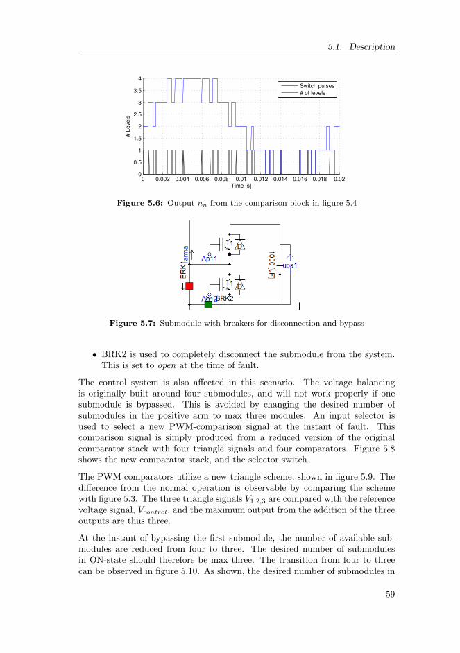
5.1. Description
0 0.002 0.004 0.006 0.008 0.01 0.012 0.014 0.016 0.018 0.020
0.5
1
1.5
2
2.5
3
3.5
4
Time [s]
# L
eve
ls
Switch pulses
# of levels
Figure 5.6: Output nn from the comparison block in figure 5.4
Figure 5.7: Submodule with breakers for disconnection and bypass
• BRK2 is used to completely disconnect the submodule from the system.This is set to open at the time of fault.
The control system is also affected in this scenario. The voltage balancingis originally built around four submodules, and will not work properly if onesubmodule is bypassed. This is avoided by changing the desired number ofsubmodules in the positive arm to max three modules. An input selector isused to select a new PWM-comparison signal at the instant of fault. Thiscomparison signal is simply produced from a reduced version of the originalcomparator stack with four triangle signals and four comparators. Figure 5.8shows the new comparator stack, and the selector switch.
The PWM comparators utilize a new triangle scheme, shown in figure 5.9. Thedifference from the normal operation is observable by comparing the schemewith figure 5.3. The three triangle signals V1,2,3 are compared with the referencevoltage signal, Vcontrol, and the maximum output from the addition of the threeoutputs are thus three.
At the instant of bypassing the first submodule, the number of available sub-modules are reduced from four to three. The desired number of submodulesin ON-state should therefore be max three. The transition from four to threecan be observed in figure 5.10. As shown, the desired number of submodules in
59

Chapter 5. Simulations
Figure 5.8: Reduced PWM comparator with three triangle-signals
0 0.005 0.01 0.015 0.02 0.025 0.03 0.035 0.04−1
−0.5
0
0.5
1
Time [s]
PW
M
V
control
Vtri1
Vtri2
Vtri3
Figure 5.9: PWM comparator scheme for the bypassed system with three sub-modules
ON-state (nn) is following the referance signal to a max number of three insteadof four. In this case, the fault occurs at t = 0.4 s. This should lead to a levelreduction to four levels for phase a. See section 5.2.3 for results.
5.1.4 The full system
Simulations were preformed on the full system, to document how the chosenconverter operates in comparison to the conventional 2-level VSC. One partof the setup is shown in figure 5.11. The figure shows one of the machinemodels, and one of the converter modules. All the converter modules are seriesconnected with the two terminals dcPlus and dcMin.
The idea is that the system should operate with any voltage controlled converter
60

5.1. Description
0.36 0.37 0.38 0.39 0.4 0.41 0.42 0.43 0.440
1
2
3
4
Time [s]
Nu
mb
er
of
su
bm
od
ule
s
n
n
Figure 5.10: Signal from comparator at the bypassing of submodule 1
Figure 5.11: PSCAD model of one machine model and one converter from thefull system
topologies. Two detailed converter modules have been used in the full-systemsimulations. Both models have been built by the author.
1. A Conventional 2-level VSC, described in section 3.2.
2. A 5-level Modular Multilevel Converter, described in section 3.5.6.
Description of the complete model can be found in [16].
Reduced to three converter modules
In the educational licence of PSCAD, the system is limited to have maximum200 nodes. This limits the size of the simulation model, and therefore the fullsystem which originally was built with averaging models in nine converters.
61

Chapter 5. Simulations
These nine modules had to be reduced to three converter modules when the fullconverter modules was implemented.
To obtain the functionality and specifications of one converter, the DC-linkvoltage was because of this reduced to 33.3 kV, from 100 kV. Although thesimulation models are reduced, the computation time is very long which leadsto limitations in the model resolution.
Generator model
As a simplification, the full system model of the proposed wind turbine usesseparate synchronous machine models, instead of one large custom-built PMSGmodel.
Specifications for the generator models are given in table 5.1:
Table 5.1: Full system - simulation model specifications
Generator parameters Value
Generator rating 1.1 MWStator resistance, rs 0.015 puStator reactance, xs 0.33 puNominal frequency fn 30 HzNominal line voltage (rms) vn 3.93 kVNominal generator current (rms) in 94 A
DC-link parameters
Total DC-link voltage Vdc 33.3 kVDC-link inductance Ldc 25 mHDC-link resistance Rdc 1.49 Ω
Converter parameters
Submodule capacitance Vdc 1000 µFPhase leg inductance Ldc 0.1 µH
Simulation sequence
Some of the following simulations show the first seconds of operation of the fullsystem, like the DC output voltages shown in section 5.2.5. Important eventsin the start-up sequence are summarized below.
0 s Initializing, DC link voltage source on (ramp up time = 0.005 s) andconnected to converters, speed reference = 0.25 pu, windspeed = 4 m/s.
62

5.2. Simulation results and analysis
5.0 s Wind speed = 10.0 m/s.
6.2 s Speed reaches 0.25 pu, and generator breaker GBRK closes.
7.0 s Speed reference = 0.8 pu.
12 s Turbine reaches speed reference of 0.8 pu.
5.2 Simulation results and analysis
This section describes and analyses the simulation results.
5.2.1 Single operated MMC converter
This section describes the simulation results from the operation of one separateMMC, as described in section 5.1.1.
The three phase voltages are shown in figure 5.12. The voltages have the clas-sical five-level staircase shape with the following voltage steps;
Vabc,5 ∈ 5.5, 2.75, 0,−2.75,−5.5 kV (5.3)
The line-to-line voltage THD is about 13 %, which is much lower than in thetwo level converter, operated in the same model. The line-to-line THD in thetwo-level model was 63 % as seen in the comparison of section 3.6.4.
Figure 5.13 shows the corresponding phase currents. The current is filteredto some extent by the not purely resistive load and the line impedances. Thecurrent THD is about 5 %, in contrast to 12 % in the two-level converter model.
In each submodule, the capacitor voltages are captured. Figure 5.14 shows adetailed print of the four upper capacitor voltages in phase a. The voltagebalancing ensures that the voltages is kept balanced around 2.75 kV. As shownin the figure, the oscillations follow the system frequency of 50 Hz.
The MMC operates as expected in the single rectifier mode.
63

Chapter 5. Simulations
0.5 0.51 0.52 0.53 0.54 0.55 0.56−6
−4
−2
0
2
4
6
Time [s]
Ph
ase
Vo
lta
ge
[kV
]
V
a
Vb
Vc
Figure 5.12: Phase voltages Va, Vb and Vc in the separated operation of anMMC in rectifier mode.
0.5 0.51 0.52 0.53 0.54 0.55 0.56−0.2
−0.1
0
0.1
0.2
Time [s]
Cu
rre
nt
[kA
]
Ia
Ib
Ic
Figure 5.13: Line currents Ia, Ib and Ic in the separated operation of an MMCconverter in rectifier mode.
0 0.1 0.2 0.3 0.4 0.5 0.6 0.7 0.8 0.9 1−0.5
0
0.5
1
1.5
2
2.5
3
0.64 0.66 0.68 0.7 0.72
2.6
2.7
2.8
2.9
V
C1
VC2
VC3
VC4
Figure 5.14: Submodule capacitor voltages VC1 - VC4, phase a, upper arm.Separated operation of an MMC converter in rectifier mode.
64

5.2. Simulation results and analysis
5.2.2 MMC voltage balancing control algorithm
Simulations in PSCAD confirms the basic idea of voltage balancing by thesorting algorithm. As shown in figure 5.15, the capacitor voltages in the upperarm of phase a is balanced around 2.75 kV, which is one fourth of the DC-linkvoltage. At t = 0.5 s, the capacitor voltage sorting is disabled in the calculationblock, and as expected the voltages drift towards zero and Vdc
2 = 5.5 kV.
0 0.2 0.4 0.6 0.8 10
1
2
3
4
5
6
Time [s]
Vo
lta
ge
[kV
]
VC1
VC2
VC3
VC4
Figure 5.15: Submodule capacitor voltages in upper arm, phase a: The voltagebalancing control is disabled at t = 0.5 s, resulting in driftingcapacitor voltages.
The phase voltage is a stable five level voltage until the balancing is disabled.At t=0.7s the voltages are totally imbalanced, and the converter acts as a threelevel converter. The voltage waveform is shown in figure 5.16.
0.45 0.5 0.55 0.6 0.65 0.7 0.75−6
−4
−2
0
2
4
6
Time [s]
Vo
lta
ge
[kV
]
Figure 5.16: Phase voltage Va, capacitor voltage balancing control disabled att = 0.5 s, resulting in a three-level functionality.
Figure 5.17 shows the phase current ia before disabling the balancing. Asobserved from figure 5.18, the phase current is seriously distorted after disablingthe voltage balancing.
The measured total harmonic distortion (THD) in the line to line voltage Vabincreases from 14% (before disabling balancing) to 35% (after t = 0.7s).
65

Chapter 5. Simulations
0.1 0.105 0.11 0.115 0.12 0.125 0.13 0.135 0.14−0.1
−0.05
0
0.05
0.1
Time [s]
Cu
rre
nt
[kA
]
ia
Figure 5.17: Phase current ia: Before capacitor voltage balancing control isdisabled at 0.4 s.
0.8 0.805 0.81 0.815 0.82 0.825 0.83 0.835−0.06
−0.04
−0.02
0
0.02
0.04
0.06
Time [s]
Cu
rre
nt
[kA
]
ia
Figure 5.18: Phase current ia: After capacitor voltage balancing control is dis-abled, and the phase voltage has developed a three-level form.
66

5.2. Simulation results and analysis
5.2.3 Redundancy, n-1 scenario
When bypassing one submodule in phase a, upper arm, the following observa-tions can be made:
• The number of submodules in the upper arm are reduced to three. Thisis previously shown in figure 5.10.
• The voltages in each of the remaining submodules are increased.
• The phase voltage in the converter is reduced to four levels.
• The harmonic content in voltages and currents is increased.
Submodule capacitor voltages
Figure 5.19 shows the capacitor voltages in the four submodules in the upperarm of phase a. The bypassing is executed at t = 0.4 s. At this instant, theDC-link voltage is divided among three submodules instead of four. This meansthat the voltages should balance around:
VCi,4 =11 kV
4= 2.75 kV VCi,3 =
11 kV3
= 3.67 kV (5.4)
0 0.2 0.4 0.6 0.8 10
3.67
1
2
3
4
2.75
Time [s]
Vo
lta
ge
[kV
]
VC1
VC2
VC3
VC4
Figure 5.19: Capacitor voltages, upper arm, phase a: Redundancy test at t =0.4 s. The first submodule of phase a is bypassed.
The result from the simulation scenario shows the same behaviour as expected.The voltage in submodule 1, VC1, remains at 2.75 kV after the disconnection.The voltage in the three other submodules increases to be balanced at 3.67 kVafter the disconnection and bypass at t = 0.4 s.
The capacitors have to be over-rated to withstand the operation with bypassedunits. In the current scenario, the over-rating should therefore exceed a factorof:
67

Chapter 5. Simulations
Kred =3.67
2.75= 1.33 (5.5)
I.e. the the voltage rating should be at least 3.67 kV, an over-rating of 33 % fromthe normal operation voltage. With an increasing number of levels, this factoris reduced. Depending on the redundancy factor, a converter with more levelsis generally possible to operate with a higher amount of bypassed submodules.
A small overshoot is experienced before new balancing is obtained. This willalso affect the dimensioning of the capacitors, and should therefore be includedin a more thorough system design.
Phase voltages
The phase voltages are captured to see the influence from the submodule bypass.A detailed view of the phase voltages are included in figure 5.20.
0.35 0.36 0.37 0.38 0.39 0.4 0.41 0.42 0.43 0.44
−5
0
5
0.35 0.36 0.37 0.38 0.39 0.4 0.41 0.42 0.43 0.44
−5
0
5
Voltage [kV
]
0.35 0.36 0.37 0.38 0.39 0.4 0.41 0.42 0.43 0.44
−5
0
5
Time [s]
Va
Vb
Vc
Figure 5.20: Phase voltages Va, Vb, Vc: Redundancy test: The first submoduleof phase a is bypassed at t = 0.4 s.
As illustrated in figure 5.20, only phase a is influenced by the short circuit ofsubmodule 1. The voltage shape in phase a is as expected reduced from fivelevels to four levels. Phase voltages b and c are not affected, and maintains thesame shape after the bypass of submodule 1 in phase a.
Line-to-line voltages
The line-to-line voltages Vab and Vac are affected, as described in figure 5.21.This corresponds with the phase voltages in figure 5.20, where only phase ais affected by the submodule bypass. Since neither of the two phase voltagesVb and Vc are affected, the line-to-line voltage between these two phases, Vbcremains unchanged after the bypass at t = 0.4 s.
68

5.2. Simulation results and analysis
0.35 0.36 0.37 0.38 0.39 0.4 0.41 0.42 0.43 0.44 0.45−15
−10
−5
0
5
10
15
Time [s]
Voltage [kV
]
V
ab
Vac
Vbc
Figure 5.21: Line-to-line voltages Vab, Vbc and Vac: Redundancy test: The firstsubmodule of phase a is bypassed at t = 0.4 s.
Phase currents
The phase currents are also investigated to see the influence from the alteredphase voltage after a submodule bypass. The measurements are done per phasein PSCAD, and shown in figure 5.22.
0.35 0.36 0.37 0.38 0.39 0.4 0.41 0.42 0.43 0.44
−0.05
0
0.05
0.35 0.36 0.37 0.38 0.39 0.4 0.41 0.42 0.43 0.44
−0.05
0
0.05
Cu
rre
nt
[kA
]
0.35 0.36 0.37 0.38 0.39 0.4 0.41 0.42 0.43 0.44
−0.05
0
0.05
Time [s]
Ia
Ib
Ic
Figure 5.22: Phase currents Ia, Ib, Ic. Redundancy test: The first submoduleof phase a is bypassed at t = 0.4 s.
As for the phase voltages, there is no significant change in the phase currentsfor the two phases c and c. Phase a is slightly affected, as seen in figure 5.22.
THD
To quantify the distortion in the voltage, the Total Harmonic Distortion ismeasured in the line-line voltage, Vab. The bypass results in an increase inTHD of 65%. This is illustrated in figure 5.23.
69
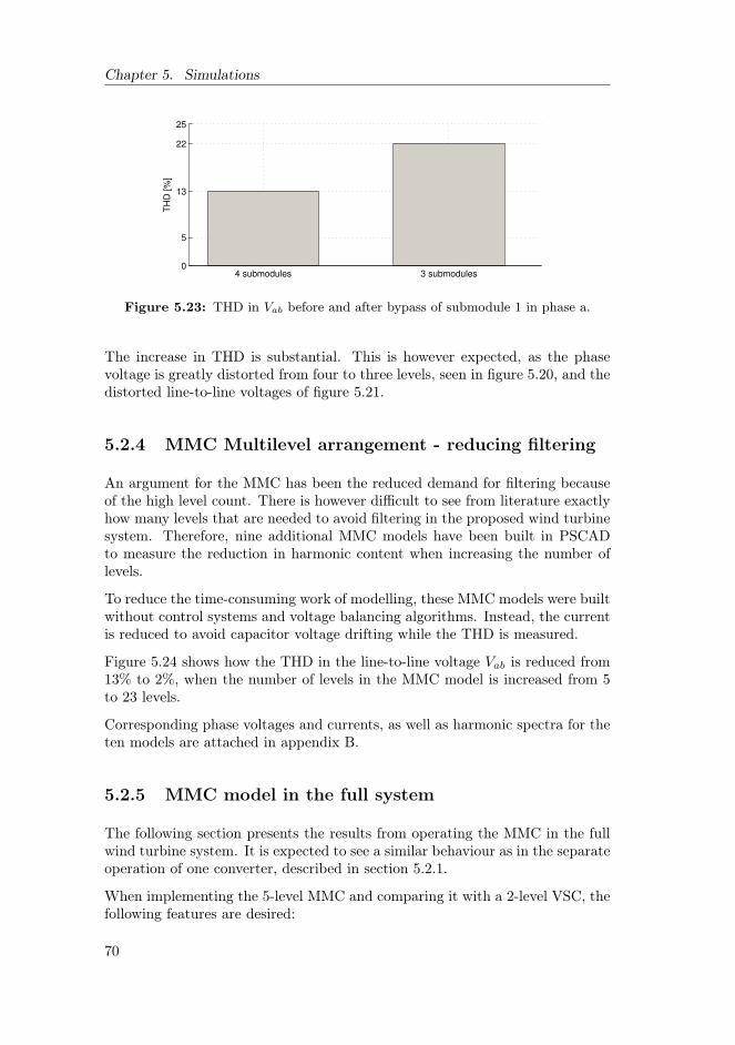
Chapter 5. Simulations
4 submodules 3 submodules0
5
13
22
25
TH
D [%
]
Figure 5.23: THD in Vab before and after bypass of submodule 1 in phase a.
The increase in THD is substantial. This is however expected, as the phasevoltage is greatly distorted from four to three levels, seen in figure 5.20, and thedistorted line-to-line voltages of figure 5.21.
5.2.4 MMC Multilevel arrangement - reducing filtering
An argument for the MMC has been the reduced demand for filtering becauseof the high level count. There is however difficult to see from literature exactlyhow many levels that are needed to avoid filtering in the proposed wind turbinesystem. Therefore, nine additional MMC models have been built in PSCADto measure the reduction in harmonic content when increasing the number oflevels.
To reduce the time-consuming work of modelling, these MMC models were builtwithout control systems and voltage balancing algorithms. Instead, the currentis reduced to avoid capacitor voltage drifting while the THD is measured.
Figure 5.24 shows how the THD in the line-to-line voltage Vab is reduced from13% to 2%, when the number of levels in the MMC model is increased from 5to 23 levels.
Corresponding phase voltages and currents, as well as harmonic spectra for theten models are attached in appendix B.
5.2.5 MMC model in the full system
The following section presents the results from operating the MMC in the fullwind turbine system. It is expected to see a similar behaviour as in the separateoperation of one converter, described in section 5.2.1.
When implementing the 5-level MMC and comparing it with a 2-level VSC, thefollowing features are desired:
70

5.2. Simulation results and analysis
5 7 9 11 13 15 17 19 21 230
2
4
6
8
10
12
14
MMC − number of levels
TH
D [
%]
THD
Figure 5.24: The reduction in THD in line-line voltage Vab when the numberof levels is increased in MMC models from 5 to 23 levels.
• All MMC features should function as expected. This means especiallyfunctions like submodule voltage balancing.
• The voltage shapes should have the expected 5-level shape as shown insimulations of the separate MMC model, i.e. with less harmonic contentthan the two-level converter model.
• The line currents should be less distorted than in the two-level model.
• In addition to balanced submodule voltages, the output DC voltages fromeach converter module should balance.
• The system itself should function in the same way, and not be negativelyaffected by the introduction of the MMC.
The turbine is started up with the sequence described in 5.1.4. Figure 5.25shows the rotational speed in the turbine. This figure is included to explain theevents observed in simulations that show the first seconds of operation, like theDC-link voltages in section 5.2.5. Some speed is built up before the generator isconnected, and a very hard ramp up is set to get the system up to operationalspeed. This is not realistic, but implemented to shorten the simulation time.
Voltage waveforms
Both phase-to-ground and line-to-line voltages are recorded at the input of oneconverter block in the full system. The full system with conventional threephase, 2-level converters is used as baseline for the comparison.
71

Chapter 5. Simulations
0 5 10 150
0.2
0.4
0.6
0.8
1
Time [s]
ω [pu]
Rotational speed
Speed reference
Figure 5.25: Startup sequence of the full system: The rotational speed of gen-erator 1 and its reference.
The three graphs in figure 5.26 show the phase-to-ground voltage Va when a2-level converter is used. Because of the grounding reference and the series con-nection of the converter modules, there is a DC offset of ±11.1 kV in converter1 and 3. The inductance in the DC-link (Ldc) is set to zero to illustrate the typ-ical two level switching pattern. When the DC-link inductance is included, thephase voltage is similar but with a sinusoidal component following the systemfrequency. The DC-link voltages seems to be balanced, since all three phasevoltage shapes have the same amplitude.
13.51 13.52 13.53 13.54 13.55 13.56 13.57−20
−10
0
10
20
Time [s]
Voltage [kV
]
V
a, conv. 1
Va, conv. 2
Va, conv. 3
Figure 5.26: Full system model with 2-level converters. Phase-to-ground volt-age Va in all three converters. Ldc = 0
A more detailed view of all the three phase voltages in converter 1 is shown infigure 5.27.
The line-to-line voltage Vab in the upper two-level converter is shown in figure5.28. The voltage show a typical shape of a two level line-to-line voltage.
When implementing the five-level MMC instead of the two-level converter, the
72
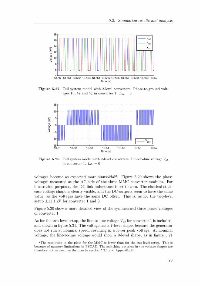
5.2. Simulation results and analysis
13.56 13.561 13.562 13.563 13.564 13.565 13.566 13.567 13.568 13.569 13.574
6
8
10
12
14
16
18
Time [s]
Voltage [kV
]
V
a1
Vb1
Vc1
Figure 5.27: Full system model with 2-level converters. Phase-to-ground volt-ages Va, Vb and Vc in converter 1. Ldc = 0
13.51 13.52 13.53 13.54 13.55 13.56 13.57−15
−10
−5
0
5
10
15
Time [s]
Voltage [kV
]
Vab1
Figure 5.28: Full system model with 2-level converters. Line-to-line voltage Vab
in converter 1. Ldc = 0
voltages become as expected more sinusoidal2. Figure 5.29 shows the phasevoltages measured at the AC side of the three MMC converter modules. Forillustration purposes, the DC-link inductance is set to zero. The classical stair-case voltage shape is clearly visible, and the DC-outputs seem to have the samevalue, as the voltages have the same DC offset. This is, as for the two-levelsetup ±11.1 kV for converter 1 and 3.
Figure 5.30 show a more detailed view of the symmetrical three phase voltagesof converter 1.
As for the two-level setup, the line-to-line voltage Vab for converter 1 is included,and shown in figure 5.31. The voltage has a 7-level shape, because the generatordoes not run at nominal speed, resulting in a lower peak voltage. At nominalvoltage, the line-to-line voltage would show a 9-level shape, as in figure 5.21
2The resolution in the plots for the MMC is lower than for the two-level setup. This isbecause of memory limitations in PSCAD. The switching patterns in the voltage shapes aretherefore not as clean as the ones in section 5.2.1 and Appendix B.
73

Chapter 5. Simulations
13.4 13.42 13.44 13.46 13.48 13.5 13.52 13.54 13.56 13.58 13.6−20
−10
0
10
20
Time [s]
Voltage [kV
]
V
a, conv. 1
Va, conv. 2
Va, conv. 3
Figure 5.29: Full system model with MMC converters. Phase voltages Va in allthree converter modules. Ldc = 0
13.4 13.42 13.44 13.46 13.48 13.5 13.52 13.54 13.56 13.58 13.64
6
8
10
12
14
16
18
Time [s]
Voltage [kV
]
V
a1
Vb1
Vc1
Figure 5.30: Full system model with MMC converters. Phase voltages Va, Vb
and Vc in converter 1. Ldc = 0
where the modulation index is ma = 0.9.
The voltage shapes indicate that the MMC functions as expected in the fullsystem as well.
Phase currents
All phase currents in the first converter module are examined. As with thevoltages, an improvement was expected with the five level MMC. Figure 5.32shows the line currents Ia, Ib and Ic in the first converter module.
As seen from the figure, the system frequency is about 25 Hz, and the smalleroscillations follow the switch frequency of 1050 Hz. The system frequency isdependent of the wind speed, and the switching frequency is set equal for allsimulations. The quality is acceptable, seen from low fuzziness in the phasecurrents in figure 5.32.
74

5.2. Simulation results and analysis
13.51 13.52 13.53 13.54 13.55 13.56 13.57−10
−5
0
5
10
Time [s]
Voltage [kV
]
Vab1
Figure 5.31: Full system model with MMC converters. Line-to-line voltage Vab
in converter 1. Ldc = 0
13.51 13.52 13.53 13.54 13.55 13.56 13.57−0.2
−0.1
0
0.1
0.2
Time [s]
Cu
rre
nt
[kA
]
Ia1
Ib1
Ic1
Figure 5.32: Full system model with standard 2-level VSC. Line current Ia, Iband Ic in the first converter module.
The same plot is done in the model with a five-level MMC, and the results arevery good. Figure 5.33 shows the corresponding line currents Ia, Ib and Ic inthe first converter module.
The expansion from two to five levels makes a substantial difference also in thecurrent. As in figure 5.32, figure 5.33 shows a system frequency of about 25Hz, and although almost not visible, a switching frequency of 1050 Hz. Thedistortion is very low.
When compared to figure 5.17 in section 5.2.3, which shows the line currentfor a nearly unfiltered five-level MMC, it is observed that the line current issmoother in the full system. This is because the machine model, described in5.1.4, contains larger reluctances than the single operated MMC model, whichfilters the current.
75

Chapter 5. Simulations
13.51 13.52 13.53 13.54 13.55 13.56 13.57−0.2
−0.1
0
0.1
0.2
Time [s]
Cu
rre
nt
[kA
]
Ia1
Ib1
Ic1
Figure 5.33: Full system model with 5-level MMC as converter. Line currentIa, Ib and Ic in first converter module.
DC voltages
Since the MMC system includes a voltage balancing control, the DC voltagesare compared. In the MMC model, the voltages in each submodule capacitorare measured. In addition, the DC output from each converter module, and thetotal DC link voltage is captured.
The MMC is expected to operate with submodule voltage balancing in the fullsystem, and be comparable to the isolated model simulations, shown in section5.2.2.
Figure 5.34 shows the DC voltage for each converter module in the full system,Vdc1, Vdc2 and Vdc3, and the full DC link voltage, Vdc,tot. The submodulevoltages for phase a, upper arm are shown in figure 5.36.
0 5 10 150
5
10
15
20
25
30
35
Time [s]
Vo
lta
ge
[kV
]
Vdc1
Vdc2
Vdc3
Vdc,tot
Figure 5.34: Converter module voltages and total DC-link voltage in the fullsystem with two-level converters.
Figure 5.35 shows the same voltages for the system with the MMC.
76
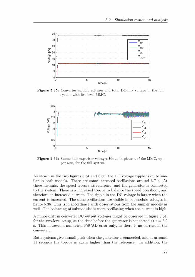
5.2. Simulation results and analysis
0 5 10 150
5
10
15
20
25
30
35
Time [s]
Voltage [kV
]
Vdc1
Vdc2
Vdc3
Vdc,tot
Figure 5.35: Converter module voltages and total DC-link voltage in the fullsystem with five-level MMC.
0 5 10 150
0.5
1
1.5
2
2.5
3
3.5
Time [s]
Voltage [kV
]
VC1
VC2
VC3
VC4
Figure 5.36: Submodule capacitor voltages VC1−4 in phase a of the MMC, up-per arm, for the full system.
As shown in the two figures 5.34 and 5.35, the DC voltage ripple is quite sim-ilar in both models. There are some increased oscillations around 6-7 s. Atthese instants, the speed crosses its reference, and the generator is connectedto the system. There is a increased torque to balance the speed overshoot, andtherefore an increased current. The ripple in the DC voltage is larger when thecurrent is increased. The same oscillations are visible in submodule voltages infigure 5.36. This is in accordance with observations from the simpler models aswell. The balancing of submodules is more oscillating when the current is high.
A minor drift in converter DC output voltages might be observed in figure 5.34,for the two-level setup, at the time before the generator is connected at t = 6.2s. This however a numerical PSCAD error only, as there is no current in theconverter.
Both systems give a small peak when the generator is connected, and at arround11 seconds the torque is again higher than the reference. In addition, the
77

Chapter 5. Simulations
setpoint changes to increase production. The current is higher, and thereforeboth models have increased DC voltage oscillations at the end of the simulation.
5.3 Discussion
5.3.1 Performance
The MMC performs well in the proposed system. The simulation results haveshown that the MMC outperforms the two-level converter in terms of voltageand current quality, at least at the generator side. A minor increase in ripple isexperienced at the grid side, which is believed to be a result from the submodulevoltage balancing. Balancing of capacitor voltages is harder in transient periods,and the model uses a very steep ramp-up. In addition, the voltage balancingalgorithm and parameters in the MMC are not fine-tuned.
Moreover, the system behaves very well to the implementation of a new con-verter model as well. This is an indication of that the system can tolerate anyvoltage source converter with a three phase input and a DC-link output.
5.3.2 Number of levels
This thesis has pointed out many reasons for increasing the number of levels.Low amount of harmonics, increased redundancy and decreased losses are ex-amples. On the other hand, increasing the number of levels will increase thecomplexity, with the consequence of a more advanced control system. From apractical point of view, it is often best to keep a system as simple as possi-ble. Reasons are that a simpler design is more reliable, and cheaper to install,maintain and supervise. But if one of the goals is to avoid series connection ofIGBTs, the multilevel approach is necessary.
Besides, simulations have shown that a five level converter results in submodulevoltages for the full system of about 3 kV, when ripple and balancing is included.With a certain overrating to protect the transistors against transients and overvoltages, this is ok if the largest IGBTs available are used. As mentioned insection 4.4, if minimizing losses is important, the amount of levels could beincreased in order to use IGBTs with lower ratings. In addition, the results insection 5.1.3 have shown that an increased level count is beneficial to make thesystem more able to operate with faulty, bypassed modules.
Section 4.3 introduced the question of how many levels that are needed to avoidfiltering. Results in section 5.2.4 have shown that the harmonic distortion inboth voltage and current is quickly reduced when the amount of levels increase.The AC current is, to some degree, filtered by inductances in the machine,and requirements to harmonic content is mainly restricted to the PCC. A high
78

5.3. Discussion
increase in levels should therefore not be motivated only by the reduction inharmonics. The generator can be built to withstand a relative high amount ofharmonic distortion, especially compared to customer appliances in larger grids.It will instead be a question of price and losses, and the complexity involved ina final mass production of the turbine.
An optimization is in the end required, to come up with the best number oflevels, with regards to the desired combination of IGBT rating, redundancy,total harmonics, dvdt s, generator insulation and oscillating torque.
79

Chapter 5. Simulations
80

Chapter 6
Conclusions
In this thesis the five most popular multilevel converter topologies have beenpresented, and compared with focus on suitability for a special weight reducingwind turbine generator concept. The modular multilevel converter (MMC) hasseveral benefits which made it the most interesting topology for further studies:The MMC makes direct series connection of IGBTs unnecessary. In addition, itoffers high voltage quality, redundancy possibilities, lower demand for filteringand is easier expandable to a larger amount of levels than the other topologies.
Preliminary studies showed that the MMC requires balancing control to avoidcapacitor voltage drifting. The simulations of a single operated MMC havetherefore focused on the balancing strategy. A voltage balancing strategy wasimplemented and analysed to ensure correct operation of the converter. Thefeature of redundancy with module failure has also been simulated in PSCAD.
Because of today’s limitations in voltage handling of IGBTs, the MMC shouldhave at least five levels to prevent damage to IGBTs because of over voltagesin transient periods. An optimal amount of levels depend upon the desiredlevel of losses, specifications of the generator, voltage quality and a weightingof reliability versus complexity. This optimization has yet to be performed in acomplete generator design, with cooperation between generator and converterproducers.
The converter has been compared to a conventional two-level converter in afull wind turbine simulation of the proposed generator system. The MMCfunctioned well in the system, and outperformed the two-level in terms of voltagequality, as was expected. By implementing the features of a multilevel converterinto the proposed system, the system can improve in terms of reliability. Thisis very beneficial in offshore installations where accessibility is limited.
81

Chapter 6. Conclusions
82

Chapter 7
Further work
Additional work is required for a verification of the proposed combination ofconverter and generator system.
The work of this thesis has not included laboratory models. A natural con-tinuation of the work would therefore be to build a model of the MMC, andinclude the model in a prototype of the special generator. A laboratory modelwould probably highlight additional challenges with the combination, and givea better background for more detailed reliability calculations.
To optimize the number of levels in the special system, many factors have tobe considered. Among these factors are the calculation of losses, which is notthoroughly covered in this thesis. In addition, a cooperation with the producerof the generator is needed to find a satisfactory amount of harmonic components.
A benefit of multilevel converters is the possible reduction of the switchingfrequency to reduce the switching losses. Simulations in this work have had aconstant switching frequency of 1050 Hz. An interesting study would be thequestion of how low the switching frequency can be in a multilevel converter.
In addition more practical aspects of the MMC converter should be includedin a more thorough study. This includes structural issues, and detailed weightestimates.
Finally, it it worth to mention the optimization of the whole generator-convertersystem. This master’s thesis has used the proposed system with 100 kV DClink and nine converter modules as a basis, and with a desire to avoid seriesconnection of IGBTs. The choice of converter topology is very dependent of thisconfiguration, especially because of the voltage level and number of convertermodules. Another full system configuration could in total be more economical.
83

Chapter 7. Further work
84

Bibliography
[1] R. Lund. Multilevel Power Electronic Converters for Electrical MotorDrives. PhD thesis, NTNU, 2005.
[2] H. Iman Eini, Sh. Farhangi, and J.L. Schanen. A modular AC/DC rectifierbased on cascaded H-bridge rectifier. In Power Electronics and MotionControl Conference, 2008. EPE-PEMC 2008. 13th, pages 173 –180, sept.2008.
[3] J. Wen and K. Smedley. Hexagram Rectifier x2014; Active Front Endof Hexagram Inverter for Medium-Voltage Variable-Speed Drives. PowerElectronics, IEEE Transactions on, 23(6):3014 –3024, nov. 2008.
[4] J. Wen and K. Smedley. Synthesis of Multilevel Converters Based on Single-and/or Three-phase Converter Building Blocks. In Industrial ElectronicsSociety, 2007. IECON 2007. 33rd Annual Conference of the IEEE, pages1780 –1786, nov. 2007.
[5] World Wind Energy Association. World Market for Wind Turbines recoversand sets a new record, accessed may 28th, 2012. http://wwindea.org/home/index.php.
[6] IEEE. IEEE Recommended Practices and Requirements for Harmonic Con-trol in Electrical Power Systems. IEEE Std 519-1992, 1993.
[7] ABB. Success factors for Electrification on the NCS, accessed april 11th,2012. http://www.zero10.no/innleggene/Asmund_Maland.pdf.
[8] Statoil. Annual Report 2010, Electrification of offshore installations, ac-cessed april 11th, 2012. http://www.statoil.com/AnnualReport2010/.
[9] World Wind Energy Association. World Wind Energy Report 2010, ac-cessed sept. 13, 2011. http://www.wwindea.org/home/images/stories/pdfs/worldwindenergyreport2010_s.pdf.
[10] J.F. Manwell, J.G. McGowan, and A.L. Rogers. Wind Energy Explained:Theory, Design and Application. John Wiley and Sons, Ltd, 2002.
85

Bibliography
[11] Stortingets informasjonstjeneste. Samtykke til inngåelse av avtalemed Sverige om et felles marked for elsertifikater, accessed June4rd, 2012. http://www.stortinget.no/no/Saker-og-publikasjoner/Saker/Sak/?p=51456.
[12] Technoport RERC. Book of Abstracts, accessed June 3rd, 2012.http://2012.technoport.no/upload/Technoport_RERC_2012_abstract_book.pdf.
[13] Zhaoqiang Z., A. Matveev, S. Ovrebo, R. Nilssen, and A. Nysveen. Stateof the art in generator technology for offshore wind energy conversion sys-tems. In Electric Machines Drives Conference (IEMDC), 2011 IEEE In-ternational, pages 1131 –1136, 2011.
[14] J. Ribrant and L. Bertling. Survey of failures in wind power systems withfocus on Swedish wind power plants during 1997-2005. In Power Engineer-ing Society General Meeting, 2007. IEEE, pages 1 –8, june 2007.
[15] S. Gjerde and T. Undeland. Power conversion system for transformer-less offshore wind turbine. In Power Electronics and Applications (EPE2011), Proceedings of the 2011-14th European Conference on, pages 1 –10,30 2011-sept. 1 2011.
[16] S.Gjerde and T. Undeland. A Modular Series Connected Converter for a10 MW, 36 kV, Transformer-Less Offshore Wind Power Generator Drive.In Energy Procedia: DeepWind, 19-20 January 2012, Trondheim, Norway,Elsevier Ltd, 2011.
[17] E. Spooner, P. Gordon, and C.D. French. Lightweight, ironless-stator,PM generators for direct-drive wind turbines. In Power Electronics, Ma-chines and Drives, 2004. (PEMD 2004). Second International Conferenceon (Conf. Publ. No. 498), volume 1, pages 29 – 33 Vol.1, march-2 april2004.
[18] S. Gjerde and T. Undeland. Fault Tolerance of a 10 MW, 100 kV Trans-formerless Offshore Wind Turbine Concept with a Modular Converter Sys-tem. In 15th International Power Electronics and Motion Control Confer-ence, EPE-PEMC 2012 ECCE Europe, Novi Sad, Serbia, 2012.
[19] E. Koutroulis and K Kalaitzakis. Design of a maximum power trackingsystem for wind-energy- conversion applications. In Industrial Electronics,IEEE Transactions, pages 486 – 494, 2006.
[20] M. Chinchilla, S. Arnaltes, and J.C. Burgos. Control of permanent-magnetgenerators applied to variable-speed wind-energy systems connected to thegrid. Energy Conversion, IEEE Transactions on, 21(1):130 – 135, march2006.
86

Bibliography
[21] V. Blasko and V. Kaura. A new mathematical model and control of athree-phase AC-DC voltage source converter. Power Electronics, IEEETransactions on, 12(1):116 –123, jan 1997.
[22] Chandra Bajracharya, Marta Molinas, Jon Are Suul, and Tore M Un-deland. Understanding of tuning techniques of converter controllers forVSC-HVDC. IEEE Control Systems, 2008.
[23] N. Jelani and M. Molinas. Stability investigation of control system forpower electronic converter acting as load interface in AC distribution sys-tem. In Industrial Electronics (ISIE), 2011 IEEE International Symposiumon, pages 408 –413, june 2011.
[24] Thomas Ackermann. Transmission Systems for Offshore Wind Farms.Power Engineering Review, IEEE, 22(12):23 –27, december 2002.
[25] Jürgen Häfner and ABB AB HVDC Sweeden Björn Jacobson. ProactiveHybrid HVDC Breakers - A key innovation for reliable HVDC grids. InCigré: The electric power system of the future - Integrating supergrids andmicrogrids International Symposium, 2011.
[26] R.M. Nilssen J. Holto P.K. Olsen, S. Gjerde and S. Hvidsten. A Trans-formerless Generator-Converter Concept making feasible a 100 kV LowWeight Offshore Wind Turbine Part I - The Generator. In Accepted forIEEE Energy Conversion Congress & Exposition (ECCE), Raleigh, NC,USA, 2012, 2012.
[27] W. Robbins N. Mohan, T. Undeland. The Power Electronics: Converter,Applications and Design. Ed. Wiley, 2003.
[28] Mitsubishi Electric. Mitsubishi Electric HVIGBT Module Data Sheets,accessed June 4rd, 2012. http://www.mitsubishielectric.com/semiconductors/php/eSearch.php?FOLDER=/product/powermod/powmod/hvigbtmod.
[29] J. Rodriguez, Jih-Sheng Lai, and Fang Zheng Peng. Multilevel inverters:a survey of topologies, controls, and applications. Industrial Electronics,IEEE Transactions on, 49(4):724 – 738, 2002.
[30] L. Yang, C. Zhao, and X. Yang. Loss calculation method of modularmultilevel HVDC converters. In Electrical Power and Energy Conference(EPEC), 2011 IEEE, pages 97 –101, oct. 2011.
[31] D Holmes and Thomas A Lipo. Pulse Width Modulation for Power Con-verters; Principles and Practice. Wiley, 2003.
[32] Hasmukh S. Patel and Richard G. Hoft. Generalized Techniques of Har-monic Elimination and Voltage Control in Thyristor Inverters: Part I–Harmonic Elimination. Industry Applications, IEEE Transactions on, IA-9(3):310 –317, may 1973.
87

Bibliography
[33] G.S. Konstantinou and V.G. Agelidis. Performance evaluation of half-bridge cascaded multilevel converters operated with multicarrier sinusoidalPWM techniques. In Industrial Electronics and Applications, 2009. ICIEA2009. 4th IEEE Conference on, pages 3399 –3404, 2009.
[34] A. Nabae, I. Takahashi, and H. Akagi. A New Neutral-Point-ClampedPWM Inverter. Industry Applications, IEEE Transactions, IA-17(5):518–523, sept. 1981.
[35] N.S. Choi, J.G. Cho, and G.H. Cho. A general circuit topology of multilevelinverter. In Power Electronics Specialists Conference, 1991. PESC ’91Record., 22nd Annual IEEE, pages 96 –103, 1991.
[36] D. Dupuis and F. Okou. Modeling and control of a five-level Diode-Clamped Converter based StatCom. In Industrial Technology, 2009. ICIT2009. IEEE International Conference on, pages 1 –6, feb. 2009.
[37] T. Bruckner and S. Bemet. Loss balancing in three-level voltage sourceinverters applying active NPC switches. In Power Electronics SpecialistsConference, 2001. PESC. 2001 IEEE 32nd Annual, pages 1135 –1140 vol.2,2001.
[38] M. Khazraei, H. Sepahvand, K. Corzine, and M. Ferdowsi. A generalizedcapacitor voltage balancing scheme for flying capacitor multilevel convert-ers. In Applied Power Electronics Conference and Exposition (APEC),2010 Twenty-Fifth Annual IEEE, pages 58 –62, 2010.
[39] G.P. Adam, B. Alajmi, K.H. Ahmed, S.J. Finney, and B.W. Williams. Newflying capacitor multilevel converter. In Industrial Electronics (ISIE), 2011IEEE International Symposium on, pages 335 –339, june 2011.
[40] A. Lesnicar and R. Marquardt. An innovative modular multilevel con-verter topology suitable for a wide power range. In Power Tech ConferenceProceedings, 2003 IEEE Bologna, volume 3, page 6 pp. Vol.3, june 2003.
[41] ABB. Skagerrak HVDC Interconnections, accessed may 24th,2012. http://www.abb.com/industries/ap/db0003db004333/448a5eca0d6e15d3c12578310031e3a7.aspx.
[42] Siemens Energy. Living Energy - Siemens Debuts HVDC Pluswith San Fransisco’s Trans Bay Cable, accessed oct. 27, 2011.http://www.energy.siemens.com/hq/pool/hq/energy-topics/living-energy/issue-5/LivingEnergy_05_hvdc.pdf.
[43] ABB. ABB HVDC Reference projects, accessed oct. 27, 2011. http://www.abb.com/industries/no/9AAF400191.aspx?country=00.
[44] H. Akagi. New trends in medium-voltage power converters and motordrives. In Industrial Electronics (ISIE), 2011 IEEE International Sympo-sium on, pages 5 –14, june 2011.
88
Bibliography
[45] U.N. Gnanarathna, S.K. Chaudhary, A.M. Gole, and R. Teodorescu. Mod-ular multi-level converter based HVDC system for grid connection of off-shore wind power plant. In AC and DC Power Transmission, 2010. ACDC.9th IET International Conference on, 2010.
[46] A. Antonopoulos, L. Angquist, and H.-P. Nee. On dynamics and voltagecontrol of the Modular Multilevel Converter. In Power Electronics andApplications, 2009. EPE ’09. 13th European Conference on, pages 1 –10,sept. 2009.
[47] Qingrui Tu, Zheng Xu, and Lie Xu. Reduced Switching-Frequency Mod-ulation and Circulating Current Suppression for Modular Multilevel Con-verters. Power Delivery, IEEE Transactions on, 26(3):2009 –2017, july2011.
[48] A. Lahyani, P. Venet, G. Grellet, and P.-J. Viverge. Failure predictionof electrolytic capacitors during operation of a switchmode power supply.Power Electronics, IEEE Transactions on, 13(6):1199 –1207, nov 1998.
[49] Y. Chen, H. Li, F. Lin, F. Lv, Z. Li, and M. Zhang. Effect of interlayer airon performance of dry-type metalized film capacitor in DC, AC and pulsedapplications. Dielectrics and Electrical Insulation, IEEE Transactions on,18(4):1301 –1306, august 2011.
[50] B. Backlund, M. Rahimo, S. Klaka, and J. Siefken. Topologies, voltageratings and state of the art high power semiconductor devices for mediumvoltage wind energy conversion. In Power Electronics and Machines inWind Applications, 2009. PEMWA 2009. IEEE, pages 1 –6, june 2009.
[51] B. Jacobson et. al. ABB Sweden. VSC-HVC Transmission with CascadedTwo-Level Converters. Cigre 2010, 2010.
[52] ABB. HVDC and HVDC Light, accessed may 24th, 2012. http://www.abb.co.uk/industries/us/9AAC30100013.aspx.
[53] B. Backlund, M. Rahimo, S. Klaka, and J. Siefken. Topologies, voltageratings and state of the art high power semiconductor devices for mediumvoltage wind energy conversion. In Power Electronics and Machines inWind Applications, 2009. PEMWA 2009. IEEE, pages 1 –6, june 2009.
[54] M. Hagiwara and H. Akagi. PWM control and experiment of modularmultilevel converters. In Power Electronics Specialists Conference, 2008.PESC 2008. IEEE, pages 154 –161, june 2008.
[55] P. M. Meshram and V. B. Borghate. A novel voltage balancing method ofModular Multilevel Converter (MMC). In Energy, Automation, and Signal(ICEAS), 2011 International Conference on, pages 1 –5, 2011.
[56] R. Walpole, R. Myers, S. Myers, and K. Ye. Probability and Statistics forEngineers and Scientists (8th ed.). Prentice-Hall, 2006.
89

Bibliography
[57] Minyuan Guan, Zheng Xu, and Hairong Chen. Control and modulationstrategies for modular multilevel converter based HVDC system. In IECON2011 - 37th Annual Conference on IEEE Industrial Electronics Society,pages 849 –854, nov. 2011.
[58] Stephen J. Chapman. Fortran 90/95, For Scientists and Engineers.McGraw-Hill, 2004.
[59] Ned Mohan. Advanced Electric Drives: Analysis, Control and Modelingusing Simulink. MNPERE, 2001.
90

Appendix
91

Bibliography
92

Appendix A
DQ-transformation
For a simplified analysis, vector control employs the technique of DQ-transformationand rotating reference axis. And as seen in the block diagram for the completecontrol system, figure 2.4, the output from the current controller is referred todirect and quadrature axis. Hence, a transformation block is needed.
In rotating machines, an analytic analysis is somewhat limited by the factthat the calculations can become quite complicated when introducing time-dependent angles. The DQ-transformation is used to simplify the analysis byintroducing a rotating reference plane, called the d-q frame. By definition, thedirect axis is aligned with the rotor flux, while the rotor quadrature axis isalways perpendicular to the direct axis.
Fixed α-axis
Fixed β-axis
Rotating q-axis
Rotating d-axis
id
iq
iiβ
iα
v = vdvβ
vα
Θ
Φ
ω
Figure A.1: General principle of vector control DQ-transformation
By transforming time-dependent components like voltage, current or flux intoequivalent quantities that rotate in synchronism with the machine rotor, the
93

Appendix A. DQ-transformation
quantities are described by a constant and a constant angle. The angle isconstant because of the rotating reference, the d-q frame [59].
The transformation can be split into two parts. First, using the Clark-transformationfrom the abc-frame to the α-β frame, and then using the Park transformationfrom the α-β frame to the d-q frame. This gives the following transformationmatrices [59]:
Tabc−αβ =2
3
[1 − 1
2 − 12
0√32 −
√32
](A.1)
and,
Tαβ−dq =
[cos θ sin θ
− sin θ cos θ
](A.2)
The transformation from abc to α-β is:
Sαβ = Tabc−αβ · Sabc (A.3)
Here S represents the voltage, current or flux to be transformed.
The inverse transformation matrices are:
Tdq−αβ =
[cos θ − sin θ
sin θ cos θ
](A.4)
and,
Tαβ−abc =
1 0
− 12
√32
− 12 −
√32
(A.5)
A combination of these equations give the complete transformation from themeasured abc-frame to the rotating dq-frame [59]. These matrices assume abalanced stationary system, neglecting the zero-sequence component.
Tabc−dq =
√2
3
[cos θ cos(θ − 2π
3 ) cos(θ + 2π3 )
− sin θ − sin(θ − 2π3 ) − sin(θ + 2π
3 )
](A.6)
With the following inverse transformation matrix:
94

Tabc−dq =
√2
3
cos θ − sin θ
cos(θ − 2π3 ) − sin(θ − 2π
3 )
cos(θ + 2π3 ) − sin(θ + 2π
3 )
(A.7)
Example
An example of dq-transformation. The voltages are defined in an abc-frame as:
Vabc =
VaVbVc
=
V cos θ
V cos(θ − 2π3 )
V cos(θ + 2π3 )
(A.8)
First a transformation to the α-β frame (Clark-transformation):
Vαβ =
[Vα
Vβ
]=
[1 − 1
2 − 12
0√32 −
√32
]·
V cos θ
V cos(θ − 2π3 )
V cos(θ + 2π3 )
=
[V cos θ
V sin θ
](A.9)
Then a transformation to the d-q frame, using the Park-transformation to getthe equivalent voltage in direct and quadrature axis reference:
Vdq =
[Vd
Vq
]=
[cos θ sin θ
− sin θ cos θ
]·[V cos θ
V sin θ
]=
[V
0
](A.10)
It can be observed that the voltage is in the direct axis only.
95

Appendix A. DQ-transformation
96

Appendix B
Multilevel simulations: MMC5-23 levels
This appendix includes the results from simulation models built for the MMCwith 5, 7, 9, 11, 13, 15, 17, 19, 21 and 23 levels. The intention of buildingall these models have been to see the reduced demand for filtering because ofreduced THD when increasing the number of levels. A graph describing thereduced THD is shown in figure 5.23.
For each model, the phase voltage, phase current and the THD in the line-to-line voltage is measured. It is worth to notice that the voltage axis of theTHD figures are, for illustration purposes, limited to 0.1, while the fundamentalharmonic stretches to 1.0.
97

Appendix B. Multilevel simulations: MMC 5-23 levels
B.1 5 levels
0 5 10 15 20 25 300
0.02
0.04
0.06
0.08
0.1
Harmonic number
Rela
tive v
oltage V
n / V
1
Figure B.1: Harmonic content in line-line voltage Vab in MMC model with 5levels
0.84 0.85 0.86 0.87 0.88 0.89 0.9−6
−4
−2
0
2
4
6
Time [s]
Vo
lta
ge
[kV
]
(a)
0.84 0.85 0.86 0.87 0.88 0.89 0.9
−0.5
0
0.5
Time [s]
Cu
rre
nt
[mA
]
(b)
Figure B.2: MMC 5-level a) Phase voltage Va b) Phase current Ia
98

B.2. 7 levels
B.2 7 levels
0 5 10 15 20 25 300
0.02
0.04
0.06
0.08
0.1
Harmonic number
Rela
tive v
oltage V
n / V
1
Figure B.3: Harmonic content in line-line voltage Vab in MMC model with 7levels
0.84 0.85 0.86 0.87 0.88 0.89 0.9−6
−4
−2
0
2
4
6
Time [s]
Vo
lta
ge
[kV
]
(a)
0.84 0.85 0.86 0.87 0.88 0.89 0.9
−0.5
0
0.5
Time [s]
Cu
rre
nt
[mA
]
(b)
Figure B.4: MMC 7-level a) Phase voltage Va b) Phase current Ia
99

Appendix B. Multilevel simulations: MMC 5-23 levels
B.3 9 levels
0 5 10 15 20 25 300
0.02
0.04
0.06
0.08
0.1
Harmonic number
Rela
tive v
oltage V
n / V
1
Figure B.5: Harmonic content in line-line voltage Vab in MMC model with 9levels
0.84 0.85 0.86 0.87 0.88 0.89 0.9−6
−4
−2
0
2
4
6
Time [s]
Vo
lta
ge
[kV
]
(a)
0.84 0.85 0.86 0.87 0.88 0.89 0.9
−0.5
0
0.5
Time [s]
Cu
rre
nt
[mA
]
(b)
Figure B.6: MMC 9-level a) Phase voltage Va b) Phase current Ia
100
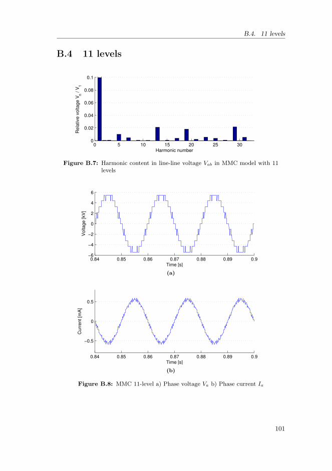
B.4. 11 levels
B.4 11 levels
0 5 10 15 20 25 300
0.02
0.04
0.06
0.08
0.1
Harmonic number
Rela
tive v
oltage V
n / V
1
Figure B.7: Harmonic content in line-line voltage Vab in MMC model with 11levels
0.84 0.85 0.86 0.87 0.88 0.89 0.9−6
−4
−2
0
2
4
6
Time [s]
Vo
lta
ge
[kV
]
(a)
0.84 0.85 0.86 0.87 0.88 0.89 0.9
−0.5
0
0.5
Time [s]
Cu
rre
nt
[mA
]
(b)
Figure B.8: MMC 11-level a) Phase voltage Va b) Phase current Ia
101

Appendix B. Multilevel simulations: MMC 5-23 levels
B.5 13 levels
0 5 10 15 20 25 300
0.02
0.04
0.06
0.08
0.1
Harmonic number
Re
lative
vo
lta
ge
Vn /
V1
Figure B.9: Harmonic content in line-line voltage Vab in MMC model with 13levels
0.84 0.85 0.86 0.87 0.88 0.89 0.9−6
−4
−2
0
2
4
6
Time [s]
Vo
lta
ge
[kV
]
(a)
0.84 0.85 0.86 0.87 0.88 0.89 0.9
−0.5
0
0.5
Time [s]
Cu
rre
nt
[mA
]
(b)
Figure B.10: MMC 13-level a) Phase voltage Va b) Phase current Ia
102

B.6. 15 levels
B.6 15 levels
0 5 10 15 20 25 300
0.02
0.04
0.06
0.08
0.1
Harmonic number
Rela
tive v
oltage V
n / V
1
Figure B.11: Harmonic content in line-line voltage Vab in MMC model with 15levels
0.84 0.85 0.86 0.87 0.88 0.89 0.9−6
−4
−2
0
2
4
6
Time [s]
Vo
lta
ge
[kV
]
(a)
0.84 0.85 0.86 0.87 0.88 0.89 0.9
−0.5
0
0.5
Time [s]
Cu
rre
nt
[mA
]
(b)
Figure B.12: MMC 15-level a) Phase voltage Va b) Phase current Ia
103

Appendix B. Multilevel simulations: MMC 5-23 levels
B.7 17 levels
0 5 10 15 20 25 300
0.02
0.04
0.06
0.08
0.1
Harmonic number
Rela
tive v
oltage V
n / V
1
Figure B.13: Harmonic content in line-line voltage Vab in MMC model with 17levels
0.84 0.85 0.86 0.87 0.88 0.89 0.9−6
−4
−2
0
2
4
6
Time [s]
Vo
lta
ge
[kV
]
(a)
0.84 0.85 0.86 0.87 0.88 0.89 0.9
−0.5
0
0.5
Time [s]
Cu
rre
nt
[mA
]
(b)
Figure B.14: MMC 17-level a) Phase voltage Va b) Phase current Ia
104

B.8. 19 levels
B.8 19 levels
0 5 10 15 20 25 300
0.02
0.04
0.06
0.08
0.1
Harmonic number
Rela
tive v
oltage V
n / V
1
Figure B.15: Harmonic content in line-line voltage Vab in MMC model with 19levels
0.84 0.85 0.86 0.87 0.88 0.89 0.9−6
−4
−2
0
2
4
6
Time [s]
Vo
lta
ge
[kV
]
(a)
0.84 0.85 0.86 0.87 0.88 0.89 0.9
−0.5
0
0.5
Time [s]
Cu
rre
nt
[mA
]
(b)
Figure B.16: MMC 19-level a) Phase voltage Va b) Phase current Ia
105
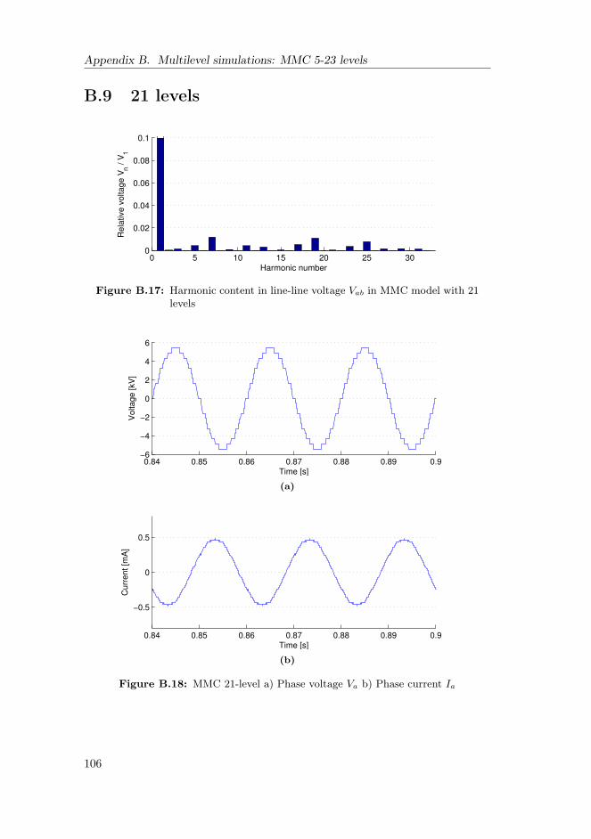
Appendix B. Multilevel simulations: MMC 5-23 levels
B.9 21 levels
0 5 10 15 20 25 300
0.02
0.04
0.06
0.08
0.1
Harmonic number
Rela
tive v
oltage V
n / V
1
Figure B.17: Harmonic content in line-line voltage Vab in MMC model with 21levels
0.84 0.85 0.86 0.87 0.88 0.89 0.9−6
−4
−2
0
2
4
6
Time [s]
Vo
lta
ge
[kV
]
(a)
0.84 0.85 0.86 0.87 0.88 0.89 0.9
−0.5
0
0.5
Time [s]
Cu
rre
nt
[mA
]
(b)
Figure B.18: MMC 21-level a) Phase voltage Va b) Phase current Ia
106

B.10. 23 levels
B.10 23 levels
0 5 10 15 20 25 300
0.02
0.04
0.06
0.08
0.1
Harmonic number
Rela
tive v
oltage V
n / V
1
Figure B.19: Harmonic content in line-line voltage Vab in MMC model with 23levels
0.84 0.85 0.86 0.87 0.88 0.89 0.9−6
−4
−2
0
2
4
6
Time [s]
Vo
lta
ge
[kV
]
(a)
0.84 0.85 0.86 0.87 0.88 0.89 0.9
−0.5
0
0.5
Time [s]
Cu
rre
nt
[mA
]
(b)
Figure B.20: MMC 23-level a) Phase voltage Va b) Phase current Ia
107

Appendix B. Multilevel simulations: MMC 5-23 levels
108

Appendix C
Fortran code: Balancing block
This appendix describes the Fortran code implemented in the capacitor voltagebalancing block. The operation of the block is described in section 4.5. A blockdiagram is also given in figure 4.5.
The variables are defined, using the #STORAGE to set the number of memoryallocations used for storage.
1 !Define variables2 #STORAGE REAL:83 #LOCAL REAL vcp 44 #LOCAL REAL vcn 45 #LOCAL REAL gatep 46 #LOCAL REAL gaten 47 #LOCAL REAL indexp 48 #LOCAL REAL indexn 49 #LOCAL REAL n, np , nn
The constant n is the available number of submodules in each phase arm.
10 !Set constants:11 n = 4
Previous gate signals are fetched from memory. gatep and gaten are vectorsfor the positive-arm and the negative-arm gate signals, respectively.
12 !Get the previous switchstates:13 gatep (1) = STORF(NSTORF)14 gatep (2) = STORF(NSTORF +1)15 gatep (3) = STORF(NSTORF +2)16 gatep (4) = STORF(NSTORF +3)17 gaten (1) = STORF(NSTORF +4)18 gaten (2) = STORF(NSTORF +5)
109

Appendix C. Fortran code: Balancing block
19 gaten (3) = STORF(NSTORF +6)20 gaten (4) = STORF(NSTORF +7)
To reduce the number of calculations by the block, a trigger signal is used toactivate the sorting. This signal is generated by a edge-detector, and the fol-lowing if-statement ensures that the calculations only happen when a switchingshould occur. Figures 5.4 and 5.5 show the edge-detector block:
21 IF ($clock .EQ. 1 ) THEN
The voltages in each submodule capacitor is continously (for each time-step)measured and fed to the block. The voltages are stored in two vectors; vcp andvcn, for positive and negative arm, respectively.
22 !Read the capacitor voltages into a vector vc:23 vcp (1) = $up124 vcp (2) = $up225 vcp (3) = $up326 vcp (4) = $up427 vcn (1) = $un128 vcn (2) = $un229 vcn (3) = $un330 vcn (4) = $un4
The following part index the voltages in two vectors, indexp and indexn.indexp and indexn are sorted in descending order, i.e. the position of thelargest voltage first.
31 !Find the order of the voltages:32 !Upper arm:33 indexp = (/1,1,1,1/)34 DO j = 1,435 largest = 036 pos = 137 DO i = 1,438 if (largest < vcp(i)) THEN39 largest = vcp(i)40 pos = i41 ENDIF42 END DO43 vcp(pos) = -244 indexp(j) = pos45 END DO46 !Lower arm:47 indexn = (/1,1,1,1/)48 DO j = 1,449 largest = 050 pos = 151 DO i = 1,452 if (largest < vcn(i)) THEN
110

53 largest = vcn(i)54 pos = i55 ENDIF56 END DO57 vcn(pos) = -258 indexn(j) = pos59 END DO
Input from the block shown in figure 5.4 is the desired number of ON-statesubmodules in lower (negative) arm. nn and np is the two variables containingthe desired number of ON-state submodules in lower and upper phase arm,respectively.
60 !Set the number of submodules in ON-state:61 nn = $nn62 np = n - nn
The following part is included to give the possibility to disable the balancingalgorithm at a certain instant. If disable is true, the selection of the correctsubmodules is not used.
64 IF ($disable .EQ. 1) THEN65 !Balancing turned off66 !Upper arm:67
68 DO i = 1,np69 gatep(i) = 170 END DO71 DO i = 1,n-np72 gatep(np+i) = 073 END DO74
75 !Lower arm:76 DO i = 1,nn77 gaten(i) = 178 END DO79 DO i = 1,n-nn80 gaten(nn+i) = 081 END DO82
83 ELSE
As described in section 4.5, the correct submodules are chosen to turn ON orOFF:
84 !Choose the correct sub -modules85 !Upper arm:86 IF ($ip < 0) THEN87 DO i = 1,np88 gatep(indexp(i)) = 1
111

Appendix C. Fortran code: Balancing block
89 END DO90 DO i = 1,n-np91 gatep(indexp(np+i)) = 092 END DO93 ELSE94 DO i = 1,np95 gatep(indexp(n+1-i)) = 196 END DO97 DO i = np+1,n98 gatep(indexp(n+1-i)) = 099 END DO
100 ENDIF101 !$Lower arm:102 IF ($in < 0) THEN103 DO i = 1,nn104 gaten(indexn(i)) = 1105 END DO106 DO i = 1,n-nn107 gaten(indexn(nn+i)) = 0108 END DO109 ELSE110 DO i = 1,nn111 gaten(indexn(n+1-i)) = 1112 END DO113 DO i = nn+1,n114 gaten(indexn(n+1-i)) = 0115 END DO116 ENDIF117 ENDIF118 ENDIF
The output gate signals (sw1-sw8) are updated with the correct value:119 $sw1 = gatep (1)120 $sw2 = gatep (2)121 $sw3 = gatep (3)122 $sw4 = gatep (4)123
124 $sw5 = gaten (1)125 $sw6 = gaten (2)126 $sw7 = gaten (3)127 $sw8 = gaten (4)
Finally, the gate signals are stored in memory:128 STORF(NSTORF) = gatep (1)129 STORF(NSTORF +1) = gatep (2)130 STORF(NSTORF +2) = gatep (3)131 STORF(NSTORF +3) = gatep (4)132
133 STORF(NSTORF +4) = gaten (1)134 STORF(NSTORF +5) = gaten (2)135 STORF(NSTORF +6) = gaten (3)136 STORF(NSTORF +7) = gaten (4)
112

137 NSTORF = NSTORF +8
113

Appendix C. Fortran code: Balancing block
114

Appendix D
Technoport RERC Abstract
The following abstract was accepted for a lecture presentation at the TechnoportRERC Conference in Trondheim 16-18th of April 2012.
115

Appendix D. Technoport RERC Abstract
116
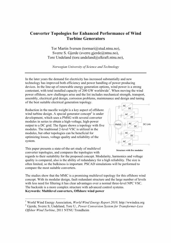
Converter Topologies for Enhanced Performance of Wind Turbine Generators
Tor Martin Iversen ([email protected]), Sverre S. Gjerde ([email protected]),
Tore Undeland ([email protected]),
Norwegian University of Science and Technology In the later years the demand for electricity has increased substantially and new technology has improved both efficiency and power handling of power producing devices. In the line-up of renewable energy generation options, wind power is a strong contestant, with total installed capacity of 200 GW worldwide1. When moving the wind power offshore, new challenges arise and the list includes mechanical strength, transport, assembly, electrical grid design, corrosion problems, maintenance and design and tuning of the best suitable electrical generation topology. Reduction in the nacelle weight is a key aspect of offshore wind turbine design. A special generator concept2 is under development, which uses a PMSG with several converter modules in series to obtain a high-voltage, high-power output to a DC grid. The figure shows a topology with five modules. The traditional 2-level VSC is utilized in the modules, but other topologies can be beneficial for optimizing losses, voltage quality and reliability of the system. This paper presents a state-of-the-art study of multilevel converter topologies, and compares the topologies with regards to their suitability for the proposed concept. Modularity, harmonics and voltage quality is compared, also is the ability of redundancy for a high reliability. The size is often limited, so the bulkiness is important. PSCAD simulations will be performed to compare the most suitable converters. The studies show that the MMC is a promising multilevel topology for this offshore wind concept. With its modular design, fault redundant structure and the large number of levels with less need for filtering it has clear advantages over a normal three-level NPC VSC. The backside is a more complex structure with advanced control systems. Keywords: Multilevel converters, Offshore wind power
1 World Wind Energy Association, World Wind Energy Report 2010, http://wwindea.org 2 Gjerde, Sverre S; Undeland, Tore U., Power Conversion System for Transformer-Less Offshor Wind Turbine, 2011 NTNU Trondheim
PMSG ACDC
ACDC
ACDC
ACDC
ACDC
DC Link
Structure with five modules

Appendix D. Technoport RERC Abstract
118

Appendix E
EPE Wind Energy and T&DChapters Seminar Paper
The following paper was accepted for an lecture presentation at the EPE WindEnergy and T&D Chapters Seminar in Aalborg, DK at the 28th and 29th ofJune 2012.
Because of the collision between the deadline of this master’s thesis and thepaper, this is not the final version. The final version will be made available atthe IEEE Explore website.
119

Appendix E. EPE Wind Energy and T&D Chapters Seminar Paper
120

Multilevel Converters for a 10 MW, 100 kVTransformer-less Offshore Wind Generator system
Tor Martin Iversen, Sverre S. Gjerde, Tore UndelandNorwegian University of Science and Technology (NTNU)
Dep. Of Electric Power EngineeringTrondheim, Norway
Email: [email protected], [email protected], [email protected]: http://www.ntnu.edu/elkraft
Keywords
<<Multilevel converters>>, <<Modular multilevel converter (MMC)>>, <<Wind energy>>,<<Transformer-less>>, <<HVDC>>
AbstractThe nacelle weight reduction is a key design criterion for offshore wind turbines, as these arereaching towards 10 MW. To overcome the weight challenge, a transformer-less concept is underdevelopment. This concept employs a special permanent magnet synchronous generator (PMSG)with an innovative system for high insulation level. The generator supplies nine series connectedconverter modules, which results in a high voltage DC output of 100 kV, reducing the totalweight of the system.The work presented here focuses on one of the 11.1 kV converter modules, and identifies themodular multilevel converter (MMC) as the best candidate for the proposed system. The comparecriteria are no direct series connection of IGBTs, efficiency, voltage quality and redundancy forincreased reliability. Simulations are performed in PSCAD/EMTDC, with focus on redundancy,submodule voltage balancing, and implementation of the MMC in full system models. Theresults show that the MMC performs well in the full system, and is therefore considered as aviable converter for the proposed system.
1 Introduction
1.1 Background and motivationThe increasing demand for electricity, combined with the necessity of reducing the CO2-emissionsis one of the greatest challenges of this century. There is a need for green energy, and theworldwide energy sector faces a huge public responsibility. A responsibility of not only providingthe possibility for continuous growth in living standards, but also securing that the growth issustainable. In addition to a greener utilization of fossil fuels like oil and gas, the use of renewableenergy sources will be an important contribution to the energy mix.Offshore wind is a relatively new approach to the generation of green electricity. Moving theelectrical power generation offshore gives several benefits, but has a comprehensive list of chal-lenges. This includes mechanical influence, fatigue, transport and assembly, electrical grid designand maintenance issues due to the scarce availability. However, the use of offshore wind has beenincreasing: 1.2 GW was installed in 2010, resulting in a worldwide total of 3.1 GW, and a shareof 1.6 % of the total wind capacity [2].
There is high activity in the developing of offshore wind, as new technology is needed to overcomethe technical and economical difficulties. As the average size in offshore wind turbines increases,from today’s 3.8 MW [4], the overall nacelle weight becomes a key issue. A weight reducingstrategy is therefore one of the motivations for this work. In addition, as a result of the scarceavailability, an optimal solution should include redundancy for increased reliability [3].

1.2 Outline of the paperThe paper is organized as follows. Part 2 presents an overview of the concept. In part 3, theconventional converter is presented along with the multilevel idea and the following multileveltopologies. A converter is chosen for further studies, and part 4 describes the simulations.Conclusions and further work are summarized in part 5 and 6, respectively.
2 The proposed turbine concept
This chapter presents first the conventional wind turbine generator/converter solutions. Theintention is to highlight some of the challenges with the conventional design in terms of weightand reliability. A new, weight-reducing concept is then presented, with possibilities of increasedreliability.
2.1 The conventional solutionsThe doubly-fed induction generator (DFIG) is today the most popular generator solution inoffshore wind applications, and stands for almost 50 % of all operational generators [4]. Aschematic of the solution is shown in figure 1a. The DFIG solution includes a gear box to stepup the rotational speed, a proportionally rated AC/AC converter to control the exitation of themachine, and a step-up transformer.
DFIG
ACAC AC grid
GEARBOX
(a)
PMSG ACDC
DCAC
AC grid
(b)
Figure 1: a) Standard DFIG solution, b) Standard PSMG solution
The gear box has a reputation of being a troublesome component, especially in offshore windturbines where the reliability is very important. According to a Swedish survey, 20 % of thedowntime for a typical turbine [5] is because of the gear box. The gear box is a large and heavymechanical unit, which has to be mounted and replaced in one piece. This means that one offew existing crane vessels has to be brought to the site. Using solutions which omit the gear boxwill therefore increase the reliability and reduce the weight.
A directly driven PMSG is such a solution, and trends show an increase in the use of these [4].The PMSG solution offers some advantages that are very useful compared to a DFIG-solution:The machine can be directly driven without the need for gearing. There is less maintenance; nobrushes nor slip-rings. The PMSG has therefore increased reliability, and increased efficiency ina larger range of wind speeds [4].
However, the step-up transformer is still included in standard PMSG solutions, as illustrated infigure 1b. This is due to the large power handling of the generator, and the standard industrialvoltage of 690 V. This results, in the MW-segment, in a very high current which needs to betransferred down the tower, and hence bulky cables. The cables have to be flexible enough tohandle the yaw control of the turbine. The transformer for large offshore turbines is thereforeplaced in the nacelle.The voltage output from the generator should therefore be increased in order to reduce thecurrent, reduce the losses and to omit the transformer in the nacelle.
2.2 The low-weight high-voltage solutionTo reduce the nacelle weight, a new generator concept is under development. The convertersolution is presented in [6], [7], and the insulation solution in [1]. A schematic of the concept is

PMSG ACDC
ACDC
ACDC
ACDC
ACDC
+
-
DC Link100 kV
ACDC
ACDC
ACDC
ACDC
11.1 kV
Figure 2: Schematic of the proposed low-weight, high voltage converter system
included in figure 2. The system consists of a special permanent magnet synchronous generatorwith nine sets of 3-phase windings. Each winding set is electrically separated from the others,and supplies a three phase converter module. Each converter module produces an output DCvoltage of 11.1 kV, and the stack of modules are series connected to obtain a desired DC voltageof 100 kV.As seen in figure 2, both the gear box and the step up transformer is now replaced by the specialPMSG and converter structure. The weight reduction is believed to be significant, and is a directresult of the special solution. There are a few arguments for this:
• The generator is built by composite materials instead of cast steel, and is therefore lighterthan a corresponding induction machine. The generator mass is typically 20-30 % of theequivalent iron-cored systems [8].
• The transformer and gear is omitted.
The schematic makes the converter part seem complex, but it is not that intricate - comparedto the alternative. Because of component limitations at the desired power and voltage rating,a single two-level full-converter structure would also need both series and parallel connectionsto handle the power rating. An additional benefit is redundancy. This is indeed one of theintentions with the proposed system [9]. With a more complex system comes more complexsupport structures. A detailed study of weight and size is not included in this work.
2.3 Contribution of this workThis work focuses on one of the converter modules of the new light-weight, high voltage conceptshown in figure 1b. The desired DC voltage is set to 100 kV, and the proposed 10 MW generatorhas nine separately isolated three phase windings. Each converter must therefore handle a DCvoltage of 11.1 kV, and a power rating of 1.1 MW. The conventional two-level converter, used ininitial concept studies, is because of this not necessarily the best choice for this system. Multi-level converters are believed to have several benefits in terms of voltage quality, efficiency, andredundancy for increased reliability. This work proposes the idea of using multilevel convertersin the proposed sustem. Five converter topologies are therefore investigated for their suitabilityfor the proposed concept, and one converter topology is chosen for studies through simulations.
3 Voltage source converters
3.1 Standard two-levelThe standard two-level voltage source converter (VSC) [10] is the reference converter. It has thesimplest structure of the evaluated, and consists of six IGBTs with diodes in anti-parallel. Figure3 shows the basic structure of such a two-level VSC. The standard two-level VSC benefits fromits simplicity, both in structure and control, and is a well-known technology. For low voltage andpower ratings it is therefore very popular.
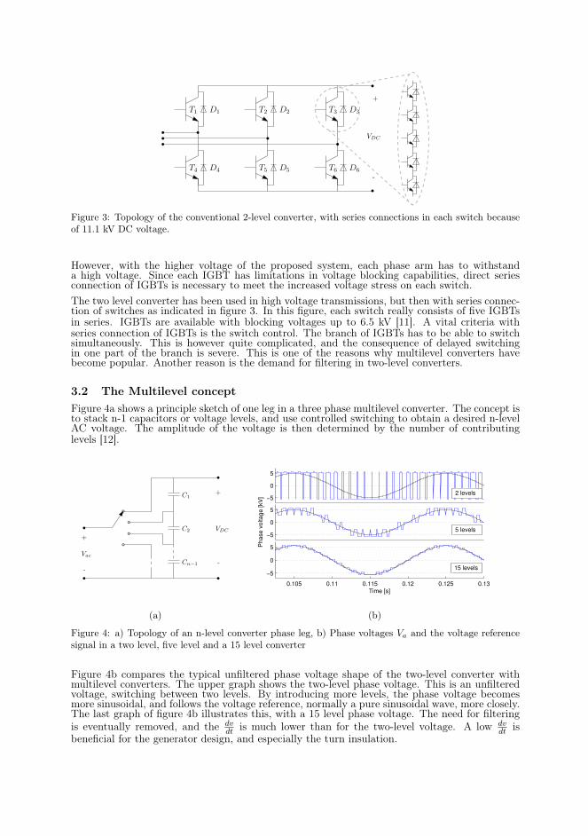
D1T1
D4T4
D2T2 D3T3
D5T5 D6T6
VDC
+
-
Figure 3: Topology of the conventional 2-level converter, with series connections in each switch becauseof 11.1 kV DC voltage.
However, with the higher voltage of the proposed system, each phase arm has to withstanda high voltage. Since each IGBT has limitations in voltage blocking capabilities, direct seriesconnection of IGBTs is necessary to meet the increased voltage stress on each switch.The two level converter has been used in high voltage transmissions, but then with series connec-tion of switches as indicated in figure 3. In this figure, each switch really consists of five IGBTsin series. IGBTs are available with blocking voltages up to 6.5 kV [11]. A vital criteria withseries connection of IGBTs is the switch control. The branch of IGBTs has to be able to switchsimultaneously. This is however quite complicated, and the consequence of delayed switchingin one part of the branch is severe. This is one of the reasons why multilevel converters havebecome popular. Another reason is the demand for filtering in two-level converters.
3.2 The Multilevel conceptFigure 4a shows a principle sketch of one leg in a three phase multilevel converter. The concept isto stack n-1 capacitors or voltage levels, and use controlled switching to obtain a desired n-levelAC voltage. The amplitude of the voltage is then determined by the number of contributinglevels [12].
C1
C2
Cn−1
Vac
VDC
+
-
+
-
(a)
−5
0
5
−5
0
5
Ph
ase
vo
lta
ge
[kV
]
0.105 0.11 0.115 0.12 0.125 0.13
−5
0
5
Time [s]
15 levels
2 levels
5 levels
(b)
Figure 4: a) Topology of an n-level converter phase leg, b) Phase voltages Va and the voltage referencesignal in a two level, five level and a 15 level converter
Figure 4b compares the typical unfiltered phase voltage shape of the two-level converter withmultilevel converters. The upper graph shows the two-level phase voltage. This is an unfilteredvoltage, switching between two levels. By introducing more levels, the phase voltage becomesmore sinusoidal, and follows the voltage reference, normally a pure sinusoidal wave, more closely.The last graph of figure 4b illustrates this, with a 15 level phase voltage. The need for filteringis eventually removed, and the dv
dt is much lower than for the two-level voltage. A low dvdt is
beneficial for the generator design, and especially the turn insulation.

3.2.1 Advantages
Some of the advantages with multilevel converters are:
• The multilevel divides the total voltage into multiple levels, which results in a lower dvdt .
• The losses in a converter include mainly conduction losses and switching losses [13]. Re-duced switching frequency makes the reduction of switching losses possible.
• The harmonic distortion is reduced, resulting in lower loss due to harmonic components.• Some multilevel topologies make redundancy possibilities easier to implement. This makes
component failures less critical for the operation of the converter.• The filtering demand in multilevel configurations is reduced, reducing the volume and cost,
and the losses due to filtering.
3.2.2 Possible drawbacks
• The investment cost increases with more complex structures.• An increase in complexity could jeopardize the reliability.• Complex control strategies are needed. For instance, capacitor voltage balancing strategies
are necessary for most multilevel converters.
3.3 Multilevel topologiesThe five following multilevel voltage source converter topologies have been studied with regardsto their suitability for the proposed concept: Neutral Point Clamped converter (NPC) [14],Flying Capacitor converter (FC) [15], Hexagram Converter [16], Cascaded H-Bridge converter(CHB) [17] and the Modular Multilevel Converter (MMC) [18]. Table I gives a summary of theconverter properties:
Table I: Summary of topology properties
Converter Suitability Cap. volume Redundancy? Voltage quality2-l VSC Series conn. High No LowNPC Series conn. High No MediumFC Good Very high No MediumHexagram Does not fit - - -CHB Does not fit Distributed Yes HighMMC Good Distributed Yes High
Both the Hexagram Converter and the CHB does not fit the proposed concept, as they requireseparate DC loads. The FC has been excluded because of high capacitor volume and voltagebalancing issues at higher levels [12].
Of the two remaining converter topologies, the MMC has been selected as the best alternative tothe conventional two-level VSC. The NPC is the state-of-the-art converter for medium voltageapplications, but is not practically expandable to more than three levels. Consequently, thereis a need for direct series connection of IGBTs in the NPC as well as the two-level. The MMCoffers the easiest expansion of levels for good voltage quality, avoids the direct series connectionof IGBTs and has a modular structure with redundancy possibilities for increased reliability.The following simulations focuses therefore mainly on the functionality of the MMC, comparingit to the 2-level VSC. An n-level MMC diagram is illustrated in figure 5.
4 SimulationsSimulations are performed to investigate the features in operation of the MMC, both in controland structure. Furthermore, the simulations compare the MMCs suitability for the proposedsystem, with a conventional two-level VSC. A five level MMC model is built in PSCAD. Featureslike redundancy and submodule voltage balancing are implemented. In addition, the convertermodel is implemented in a simulation of the complete system.

T1
T2
C1
T1
T2
Cn−1
T1
T2
T1
T2
T1
T2
T1
T2
T1
T2
T1
T2
T1
T2
T1
T2
T1
T2
T1
T2
vavbvc
R LL L L
L L L
VDC
+
-
C1
Cn−1
C1
Cn−1
C1
Cn−1
C1
Cn−1
C1
Cn−1
Upper phase arm Submodule
Figure 5: Principal drawing of an n-level MMC
ControlCalculate Non
Vref
Voltage sortingGate
Vci
system
Non
ip, in
signals
Feedback from measurements
Figure 6: Balancing strategy
4.1 Capacitor voltage balancing strategyA voltage balancing issue was in an initial study experienced in the MMC as well. Voltagebalancing control is therefore needed for the multilevel modular converter to function as expected[19]. Without a good balancing strategy, the mid-capacitor voltages drifts towards zero, seefigure 8a, and the top and bottom modules in one arm are stressed with the whole DC-voltage.This means that the DC-link voltage is shared by the two other capacitors, and that the wholeconverter eventually acts as a three level converter - increasing the stress on each switch. Theeffect on the phase voltages is indicated in figure 8b.A balancing control is implemented in the simulation models. The strategy follows the onedescribed in [20]. The strategy is to charge those sub-modules with the lowest capacitor voltages,and discharge the sub-modules with highest capacitor voltages. A sorting algorithm ensuresthe charge or discharge of the correct sub-modules. This is possible because the voltage levelgenerated in the MMC converter depends upon the number of ON-state switches in the upperarm and the lower arm, and not by the specific order these are turned on.The capacitor voltage balancing strategy can be summed up as follows. For each switchinginstant,
1. The capacitor voltages of all capacitors are measured and indexed2. The arm current direction is identified3. The necessary number of ON-state submodules is calculated4. A selection of the sub-modules is done5. Gate pulses based on the selection of sub-modules are generated
The overall control strategy is illustrated in figure 6. The outer control system is described in[7]. The calculation of the number of ON-state submodules is done using a conventional carrier

Switch ON theNon SMs withlowest voltage Vc highest voltage Vc
Switch ON theNon SMs with
Keep current
switch states
IF
Store gate signals in memory
Vi, (i = 1, 2, ..., n)
Sort and index
voltages
iarm < 0iarm > 0
Read gate signals from memory
Measure Vi (i = 1, 2, ... , n) and iarm
IF
clock = 0
clock = 1
Fire the IGBTs
Figure 7: Schematic of the submodule voltage balancing algorithm implemented in simulations
0 0.2 0.4 0.6 0.8 10
1
2
3
4
5
6
Time [s]
Voltage [kV
]
VC1
VC2
VC3
VC4
(a)
0.45 0.5 0.55 0.6 0.65 0.7 0.75−6
−4
−2
0
2
4
6
Time [s]
Voltage [kV
]
(b)
Figure 8: a) Capacitor voltages of phase a, upper leg. Capacitor voltage balancing disabled at t = 0.5 s,b) Phase voltage Va from the instant of disabling the capacitor voltage balancing.
based pulse width modulation. A schematic showing the voltage sorting algorithm is shown infigure 7.
Simulations in PSCAD demonstrate that the sorting algorithm from [20] is required for theoperation of the MMC, as expected. As shown in figure 8, the capacitor voltages in the upperarm of phase a is balanced around 2.75 kV, which is one fourth of the DC-link voltage. At t= 0.5 s, the capacitor voltage sorting is disabled in the calculation block, and as expected thevoltages drift towards zero and Vdc = 5.5 kV, i.e. the extremities. The measured total harmonicdistortion (THD) in the line to line voltage Vab increases from 14 % (before disabling balancing)to 35 % (after t = 0.7s).
4.2 RedundancyOne benefit of the MMC, which is in line with ideas behind the proposed concept, is the possibilityof redundancy [9]. A failure of one submodule in one phase arm is included in the simulations.The voltage balancing control algorithm is changed to adjust to this bypass.The results of the bypass, described in figures 9a-d, demonstrate that the voltages in each of theremaining submodules are increased, the phase voltage in the converter is reduced to four levels,and the harmonic content in voltages and currents is increased. A fault in one of the submodulesof phase a, does only affect the phase voltage of the same phase, and the corresponding phasecurrent. This is indicated in figure 9b and 9c. The line-to-line voltages connected to phase a isalso affected, as seen in figure 9d. On this basis, the converter performs as expected, and giveswith this a redundancy to the system which increases the reliability and extends the continuousoperation of the wind turbine.

0 0.2 0.4 0.6 0.8 10
3.67
1
2
3
4
2.75
Time [s]
Vo
lta
ge
[kV
]
VC1
VC2
VC3
VC4
(a)
0.35 0.36 0.37 0.38 0.39 0.4 0.41 0.42 0.43 0.44
−5
0
5
0.35 0.36 0.37 0.38 0.39 0.4 0.41 0.42 0.43 0.44
−5
0
5
Vo
lta
ge
[kV
]
0.35 0.36 0.37 0.38 0.39 0.4 0.41 0.42 0.43 0.44
−5
0
5
Time [s]
Va
Vb
Vc
(b)
0.35 0.36 0.37 0.38 0.39 0.4 0.41 0.42 0.43 0.44
−0.05
0
0.05
0.35 0.36 0.37 0.38 0.39 0.4 0.41 0.42 0.43 0.44
−0.05
0
0.05
Cu
rre
nt
[kA
]
0.35 0.36 0.37 0.38 0.39 0.4 0.41 0.42 0.43 0.44
−0.05
0
0.05
Time [s]
Ia
Ib
Ic
(c)
0.35 0.36 0.37 0.38 0.39 0.4 0.41 0.42 0.43 0.44 0.45−15
−10
−5
0
5
10
15
Time [s]
Vo
lta
ge
[kV
]
V
ab
Vac
Vbc
(d)
Figure 9: Redundant bypass of submodule 1 in phase a, upper leg at t = 0.4 s: a) Capacitor voltages, b)Phase voltages, c) Line currents, d) Line-to-line voltages
4.3 MMC in the proposed conceptSimulations were preformed on the full system, to document how the chosen converter operatesin comparison to the conventional 2-level VSC. The idea is that the system should operate withany voltage controlled converter topologies. Description of the complete system model can befound in [6] and [7]. Due to limitations in the educational version of PSCAD, the system had tobe reduced to three converter modules. The total DC link voltage is scaled with respect to themodule rating, and reduced to one third of the original, to preserve the original voltage (of 11.1kV) in each converter module DC output.The results show that the MMC performs well in the full system, and is therefore consideredas a viable candidate. It outperforms the conventional two-level in terms of voltage quality, asexpected. Moreover, the system behaves very well to the implementation of a new convertermodel as well. This is an indication of that the system can tolerate any voltage source converterwith a three phase input and a DC-link output.As seen from figure 10a and b, the line current is less distorted in the MMC setup. The phasevoltages have the typical five level staircase waveform with decreased dv
dt , and less harmonicsthan in the two-level setup, see figure 10c and d. Because of the series connection of the threeconverter modules, the phase currents in figure 10c and d have a offset of ±11.1 kV. There is lowripple in the DC link voltages, as seen in figure 10e and f. There is however a minor increasein the oscillations of the DC voltage for the MMC, because of the submodule voltage balancingcontrol.
5 ConclusionsIn this paper the five most popular multilevel converter topologies have been compared withfocus on suitability for a special weight-reducing wind turbine generator concept. The modularmultilevel converter (MMC) has several benefits that made it the most interesting topology forfurther studies: The MMC makes direct series connection of IGBTs unnecessary. In addition,it offers high voltage quality, redundancy possibilities, lower demand for filtering and is easierexpandable to a larger amount of levels than the other topologies.The feature of redundancy is an important feature of the offshore installation, and a case ofsubmodule failure has therefore been simulated in PSCAD. A fault and disconnection of onemodule is handled by the redundancy control system, and the reliability of the system is there-fore increased. Preliminary studies showed that the MMC required balancing control to avoid

13.51 13.52 13.53 13.54 13.55 13.56 13.57−0.2
−0.1
0
0.1
0.2
Time [s]
Curr
ent [k
A]
Ia1
Ib1
Ic1
(a)
13.51 13.52 13.53 13.54 13.55 13.56 13.57−0.2
−0.1
0
0.1
0.2
Time [s]
Curr
ent [k
A]
Ia1
Ib1
Ic1
(b)
13.51 13.52 13.53 13.54 13.55 13.56 13.57−20
−10
0
10
20
Time [s]
Vo
lta
ge
[kV
]
V
a, conv. 1
Va, conv. 2
Va, conv. 3
(c)
13.4 13.42 13.44 13.46 13.48 13.5 13.52 13.54 13.56 13.58 13.6−20
−10
0
10
20
Time [s]V
olta
ge
[kV
]
V
a, conv. 1
Va, conv. 2
Va, conv. 3
(d)
0 5 10 150
5
10
15
20
25
30
35
Time [s]
Voltage [kV
]
Vdc1
Vdc2
Vdc3
Vdc,tot
(e)
0 5 10 150
5
10
15
20
25
30
35
Time [s]
Vo
lta
ge
[kV
]
Vdc1
Vdc2
Vdc3
Vdc,tot
(f)
Figure 10: Simulations of the full system models with 2-level VSC (to the left) and 5 level MMC (to theright): a) Line currents with 2-level b) Line currents with MMC c) Phase voltage a in all three convertermodules, with 2-level. d) Phase voltage a in all three converter modules, with MMC. e) DC output from2-level modules, and total DC-link voltage. f) DC output from 5-level MMC modules, and total DC-linkvoltage.
capacitor voltage drifting. The simulations of the MMC have therefore also included this feature.A voltage balancing strategy was implemented and analysed to ensure correct operation of theconverter.The MMC should have at least five levels to prevent damage to IGBTs because of over voltagesin transient periods. This is because of today’s limitations in voltage handling of IGBTs. Anoptimal amount of levels depend upon the desired level of losses, generator specifications, voltagequality and a weighting of reliability versus complexity and cost. This optimization is outsidethe scope of this work.The converter has been compared to a conventional two-level converter in a full wind turbinesimulation of the proposed generator/converter system. The MMC functioned well in the system,and outperformed the two-level VSC in terms of voltage quality, as was expected. By implement-ing the features of a multilevel converter into the proposed system, the system can improve interms of reliability. This is very beneficial in offshore installations where accessibility is limited.
6 Further workThe scope of further work includes laboratory testing of the proposed generator/converter com-bination, and an optimization to find the ideal number of levels for the MMC. This optimizationcould also consider the number of converter modules and the total DC-link voltage, which were

set for this work. Economical considerations is also left out for further work. In addition, morepractical issues like structural design and detailed weight estimates should be studied.
References
[1] P.K Olsen, S. Gjerde, R.M. Nilssen, J. Holto and S. Hvidsten,A Transformerless Generator-Converter Concept making feasible a 100 kV Low Weight Offshore Wind Turbine Part I - TheGenerator, Accepted for IEEE Energy Conversion Congress & Exposition (ECCE), Raleigh, NC,USA, 2012.
[2] World Wind Energy Association. World Wind Energy Report 2010, accessed sept. 13, 2011. http:\\www.wwindea.org
[3] Walford, C. A. Wind Turbine Reliability: Understanding and Minimizing Wind Turbine Operationand Maintenance Costs, Sandia National Laboratories, 2006
[4] Zhaoqiang Zhang, Alexey Matveev, Sigurd Ovrebo, Robert Nilssen, and Arne Nysveen. State of theart in generator technology for offshore wind energy conversion systems, In Electric Machines DrivesConference (IEMDC), 2011 IEEE International, pages 1131 - 1136, 2011.
[5] J. Ribrant and L. Bertling. Survey of failures in wind power systems with focus on Swedish windpower plants during 1997-2005, In Power Engineering Society General Meeting, 2007. IEEE, pages1 - 8, june 2007.
[6] S. Gjerde and T. Undeland. Power conversion system for transformer- less offshore wind turbine, InPower Electronics and Applications (EPE 2011), Proceedings of the 2011-14th European Conferenceon, pages 1 - 10, sept. 2011.
[7] S. Gjerde and T. Undeland. A Modular Series Connected Converter for a 10 MW, 36 kV,Transformer-Less Offshore Wind Power Generator Drive, In Energy Procedia: DeepWind, 19-20January 2012, Trondheim, Norway, Elsevier Ltd, 2011.
[8] E. Spooner, P. Gordon, and C.D. French. Lightweight, ironless-stator, PM generators for direct-drive wind turbines, In Power Electronics, Ma- chines and Drives, 2004. (PEMD 2004). SecondInternational Conference on (Conf. Publ. No. 498), volume 1, pages 29 - 33 Vol.1, march - 2 april2004.
[9] S. Gjerde and T. Undeland. Fault Tolerance of a 10 MW, 100 kV Transformerless Offshore WindTurbine Concept with a Modular Converter System, In 15th International Power Electronics andMotion Control Conference, EPE-PEMC 2012 ECCE Europe, Novi Sad, Serbia, 2012.
[10] Mohan, N; Undeland, T.M; Robbins, W.P, Power Electronics: Converters, Applications and Design,John Wiley & Sons, 2003.
[11] Mitsubishi Electric. Mitsubishi Electric HVIGBT Module Data Sheets, accessed June 4rd, 2012.http://www.mitsubishielectric.com/
[12] R. Lund. Multilevel Power Electronic Converters for Electrical Motor Drives, PhD thesis, NTNU,2005.
[13] L. Yang, C. Zhao, and X. Yang. Loss calculation method of modular multilevel HVDC converters,In Electrical Power and Energy Conference (EPEC), 2011 IEEE, pages 97 - 101, oct. 2011.
[14] A. Nabae, I. Takahashi and H. Akagi. A New Neutral-Point-Clamped PWM Inverter, IndustryApplications, IEEE Transactions, 1981.
[15] M. Khazraei, H. Sepahvand, K. Corzine, and M. Ferdowsi. A generalized capacitor voltage balancingscheme for flying capacitor multilevel converters, In Applied Power Electronics Conference andExposition (APEC), 2010 Twenty-Fifth Annual IEEE, pages 58 - 62, 2010.
[16] J. Wen and K. Smedley. Hexagram Rectifier x2014; Active Front End of Hexagram Inverter forMedium-Voltage Variable-Speed Drives, Power Electronics, IEEE Transactions on, 23(6): 3014 -3024, nov. 2008.
[17] H. Iman Eini, Sh. Farhangi, and J.L. Schanen. A modular AC/DC rectifier based on cascaded H-bridge rectifier, In Power Electronics and Motion Control Conference, 2008. EPE-PEMC 2008. 13th,pages 173 - 180, sept. 2008.
[18] A. Lesnicar and R. Marquardt. An innovative modular multilevel converter topology suitable for awide power range, In Power Tech Conference Proceedings, 2003 IEEE Bologna, volume 3, page 6pp. Vol.3, june 2003.
[19] M. Hagiwara and H. Akagi. PWM control and experiment of modular multilevel converters, In PowerElectronics Specialists Conference, 2008. PESC 2008. IEEE, pages 154 - 161, june 2008.
[20] P. M. Meshram and V. B. Borghate. A novel voltage balancing method of Modular Multilevel Con-verter (MMC), In Energy, Automation, and Signal (ICEAS), 2011 International Conference on,pages 1 - 5, 2011.


![[5]the Age of Multilevel Converters Arrives](https://img.pdfslide.net/doc/110x75/553318214a795998578b47e1/5the-age-of-multilevel-converters-arrives.jpg)