Embed Size (px)
Citation preview

Multimedia Database
Final Report
Omid Anvar
Michael Harvey
Justin Johnson
April 28, 2016
CS 4264 Multimedia, Hypertext, and Information Access
Professor: Dr. Edward Fox
Virginia Polytechnic Institute and State University
Blacksburg, Virginia 24061
Client: Dr. Christopher Zobel
1
Executive Summary
Throughout this report, our team illustrates the entire process for the creation of a website to
interact with a multimedia database. Our team intended to create a centralized system where
both undergraduate and graduate Computer Science students at Virginia Tech can upload their
personal projects for all instructors who are affiliated with the university to view. The overall
goal of this project was to create a system to allow a user a way to view other user's profiles in
order to facilitate the ability to find research candidates and opportunities. Our team hopes that
this proof-of-concept project can have a greater impact in the future by being expanded upon to
include all university students. However, since our goal was to create a prototype, we have
limited the number of students who have access to the system to merely Computer Science
students. In order to create a successful prototype for our client, we had to first, through careful
discussion, create the requirements for both the database and website. Next, came the design
phase which outlines the prototype’s technologies and overall structure. In the implementation
and prototype sections, we go into detail about every aspect of the prototype’s capabilities.
Finally, in the testing section our team discusses the various metrics deployed to determine the
successfulness of the prototype. Furthermore, we discuss the future plans for the project once we
have graduated and the valuable lessons our team learned from this experience.

2
Table of Contents
Executive Summary................................................................................................................1
Table of Figures........................................................................................................................3
Table of Tables.........................................................................................................................4
User Manual..............................................................................................................................5
Developers Manual.................................................................................................................9
1 – Requirements...............................................................................................................9
1.1 - Client Information........................................................................................9
1.2 - Objectives.......................................................................................................9
1.3 - Justification....................................................................................................9
1.4 - Statement of Functionality...........................................................................9
1.5 - Performance................................................................................................10
1.6 - Reporting.....................................................................................................10
2 – Design and Implementation......................................................................................11
2.1 - Database.......................................................................................................11
2.2 - Website.........................................................................................................12
2.3 - Backend........................................................................................................12
2.4 - Timeline (Scope)..........................................................................................12
2.5 - Hardware, Software, and Technology.......................................................14
2.6 - Security and Privacy...................................................................................14
2.7 - Domain Name..............................................................................................14
3 – Prototype and Refinement........................................................................................14
3.1 - Database.......................................................................................................14
3.2 - Website.........................................................................................................15
3.3 - Backend........................................................................................................16
4 – Testing.........................................................................................................................17
4.1 - Database.......................................................................................................17
4.2 - Website and Backend.................................................................................21
5 – Conclusion..................................................................................................................21
5.1 - Future Work................................................................................................21
5.2 - Lessons Learned..........................................................................................22
5.3 - Acknowledgements......................................................................................23
Appendix...................................................................................................................................24
Figure 16...........................................................................................................................24
Tables 1 - 5........................................................................................................................25
Terminology......................................................................................................................27
References.........................................................................................................................29
3
Table of Figures
Figure 1 - Website homepage.................................................................................................5
Figure 2 - Account creation page...........................................................................................6
Figure 3 - Profile page.............................................................................................................7
Figure 4 - Search page.............................................................................................................7
Figure 5 - Java web architecture...........................................................................................11
Figure 6 - Insertion data displayed.......................................................................................18
Figure 7 - Successful insertion...............................................................................................18
Figure 8 - Depicts a row about to be deleted........................................................................19
Figure 9 - Successful deletion.................................................................................................19
Figure 10 - Depicts original PID............................................................................................19
Figure 11 - Depicts new PID..................................................................................................19
Figure 12 - Illustrates that change took place......................................................................20
Figure 13 - Depicts that PID change was successful............................................................20
Figure 14 - Simple query from person table.........................................................................20
Figure 15 - Query from multiple tables.................................................................................21.
Figure 16 - EER diagram........................................................................................................24
4
Table of Tables
Table 1 - Person......................................................................................................................25 Table 2 - Student....................................................................................................................25 Table 3 - Faculty.....................................................................................................................26 Table 4 - Media File...............................................................................................................26 Table 5 - Department.............................................................................................................26
5
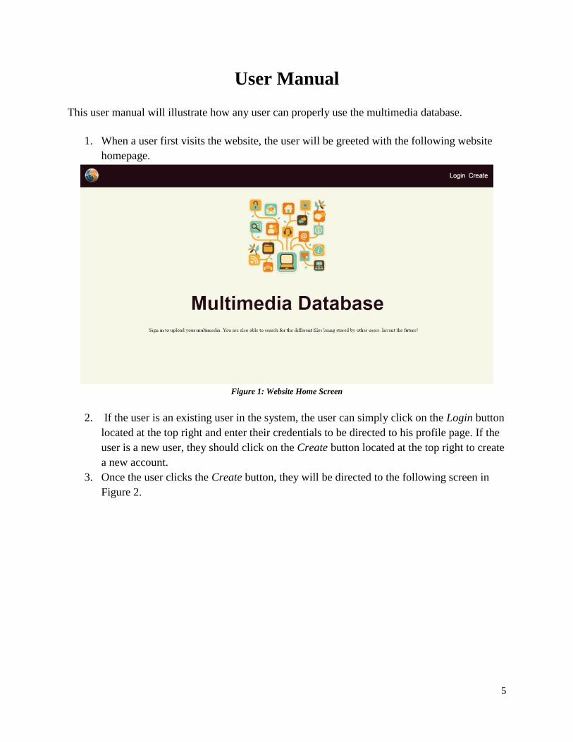
User Manual
This user manual will illustrate how any user can properly use the multimedia database.
1. When a user first visits the website, the user will be greeted with the following website
homepage.
Figure 1: Website Home Screen
2. If the user is an existing user in the system, the user can simply click on the Login button
located at the top right and enter their credentials to be directed to his profile page. If the
user is a new user, they should click on the Create button located at the top right to create
a new account.
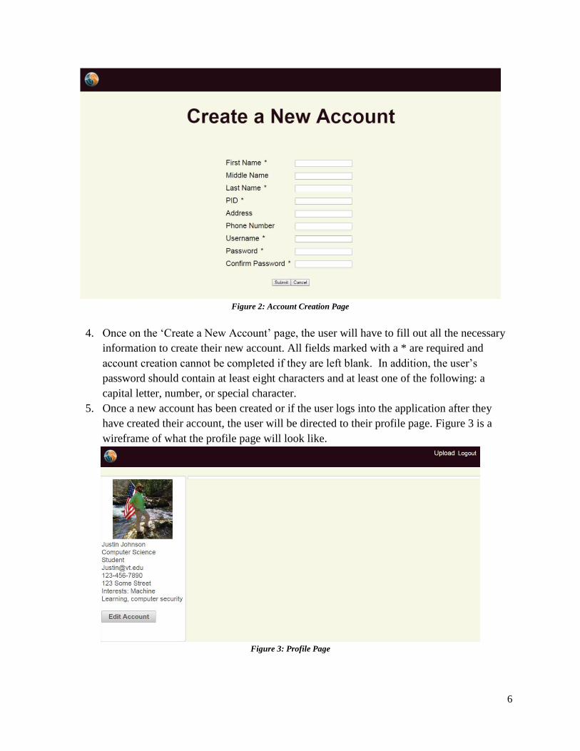
3. Once the user clicks the Create button, they will be directed to the following screen in
Figure 2.
6
Figure 2: Account Creation Page
4. Once on the ‘Create a New Account’ page, the user will have to fill out all the necessary
information to create their new account. All fields marked with a * are required and
account creation cannot be completed if they are left blank. In addition, the user’s
password should contain at least eight characters and at least one of the following: a
capital letter, number, or special character.
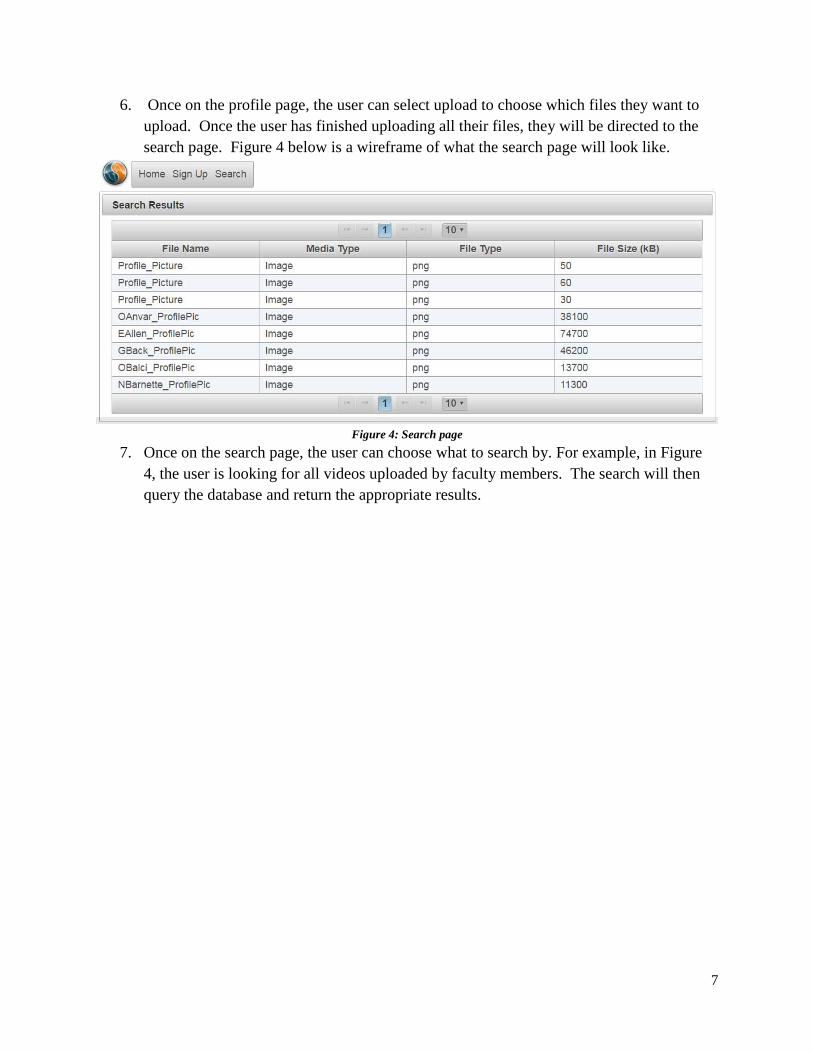
5. Once a new account has been created or if the user logs into the application after they
have created their account, the user will be directed to their profile page. Figure 3 is a
wireframe of what the profile page will look like.
Figure 3: Profile Page
7
6. Once on the profile page, the user can select upload to choose which files they want to
upload. Once the user has finished uploading all their files, they will be directed to the
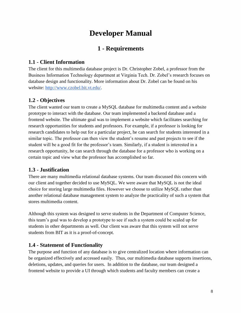
search page. Figure 4 below is a wireframe of what the search page will look like.
Figure 4: Search page
7. Once on the search page, the user can choose what to search by. For example, in Figure
4, the user is looking for all videos uploaded by faculty members. The search will then
query the database and return the appropriate results.
8
Developer Manual
1 - Requirements
1.1 - Client Information
The client for this multimedia database project is Dr. Christopher Zobel, a professor from the
Business Information Technology department at Virginia Tech. Dr. Zobel’s research focuses on
database design and functionality. More information about Dr. Zobel can be found on his
website: http://www.czobel.bit.vt.edu/.
1.2 - Objectives
The client wanted our team to create a MySQL database for multimedia content and a website
prototype to interact with the database. Our team implemented a backend database and a
frontend website. The ultimate goal was to implement a website which facilitates searching for
research opportunities for students and professors. For example, if a professor is looking for
research candidates to help out for a particular project, he can search for students interested in a
similar topic. The professor can then view the student’s resume and past projects to see if the
student will be a good fit for the professor’s team. Similarly, if a student is interested in a
research opportunity, he can search through the database for a professor who is working on a
certain topic and view what the professor has accomplished so far.
1.3 - Justification
There are many multimedia relational database systems. Our team discussed this concern with
our client and together decided to use MySQL. We were aware that MySQL is not the ideal
choice for storing large multimedia files. However we choose to utilize MySQL rather than
another relational database management system to analyze the practicality of such a system that
stores multimedia content.
Although this system was designed to serve students in the Department of Computer Science,
this team’s goal was to develop a prototype to see if such a system could be scaled up for
students in other departments as well. Our client was aware that this system will not serve
students from BIT as it is a proof-of-concept.
1.4 - Statement of Functionality
The purpose and function of any database is to give centralized location where information can
be organized effectively and accessed easily. Thus, our multimedia database supports insertions,
deletions, updates, and queries for users. In addition to the database, our team designed a
frontend website to provide a UI through which students and faculty members can create a
9
profile to store all their personal information and projects. The backend will link the website and
the database.
1.5 - Performance
It is essential that the UI respond to user input and requests in a timely manner. With that in
mind, the following performance goals have been set by our client. The home page for the
website must load and display within two seconds of the initial query for any user regardless of
connection speed. The system must also authenticate a user and display their profile page in less
than two seconds. In addition, any database query should complete in less than two seconds. The
database should also be able to delete tables in less than two seconds as well. Since
phpMyAdmin does not display the time for insertions and updates, there is no way to measure
their respective performances. The UI will display multimedia content in less than three
seconds.
1.6 - Reporting
All databases keep transaction logs for whenever a change is made to the database. However,
due to fact that this is a proof-of-concept, this database will not keep a transaction log. In
addition, it is industry standard and general good practice for databases create backups
periodically. Again, since our team is creating a proof-of-concept our database will not create
backups. However, below in the future work section there is description about plans to
incorporate transaction logs and backups.
10
2 - Design and Implementation
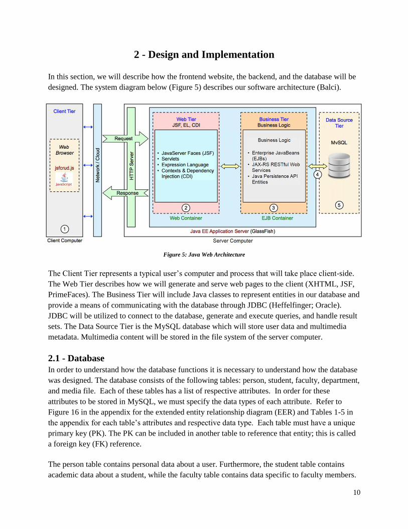
In this section, we will describe how the frontend website, the backend, and the database will be
designed. The system diagram below (Figure 5) describes our software architecture (Balci).
Figure 5: Java Web Architecture
The Client Tier represents a typical user’s computer and process that will take place client-side.
The Web Tier describes how we will generate and serve web pages to the client (XHTML, JSF,
PrimeFaces). The Business Tier will include Java classes to represent entities in our database and
provide a means of communicating with the database through JDBC (Heffelfinger; Oracle).
JDBC will be utilized to connect to the database, generate and execute queries, and handle result
sets. The Data Source Tier is the MySQL database which will store user data and multimedia
metadata. Multimedia content will be stored in the file system of the server computer.
2.1 - Database
In order to understand how the database functions it is necessary to understand how the database
was designed. The database consists of the following tables: person, student, faculty, department,
and media file. Each of these tables has a list of respective attributes. In order for these
attributes to be stored in MySQL, we must specify the data types of each attribute. Refer to
Figure 16 in the appendix for the extended entity relationship diagram (EER) and Tables 1-5 in
the appendix for each table’s attributes and respective data type. Each table must have a unique
primary key (PK). The PK can be included in another table to reference that entity; this is called
a foreign key (FK) reference.
The person table contains personal data about a user. Furthermore, the student table contains
academic data about a student, while the faculty table contains data specific to faculty members.

11
The department table corresponds to each person’s department. The student and faculty tables
are both subtypes of the person super-type. In relational database design, much like object-
oriented programming, a subtype contains all the attributes of its super-type as well as extra
properties.
Each individual upload is limited to a maximum size of one gigabyte, and each user may have a
maximum of five gigabytes of total data stored in the database. We predict severe performance
issues for uploads of a larger size.
Since multimedia information can take up a large amount of space, it is impractical to store all of
the media in the database itself. Instead, the media file table will store a file path to the
multimedia data on the server computer. There will be a relative file path linked to the actual
server computer’s file system where the data will be stored and retrieved from.
2.2 - Website
The website follows an approach that is being used by companies such as Microsoft, Google, and
Apple - flat. With simple colors and grid layouts of the information, the user will not be
distracted by unneeded graphics. There are four pages associated with the website: homepage,
profile page, account creation page, and a search page. The first page that the user will access
will be the homepage. From the homepage, the user can either log into an existing account or
create a new account. After the user creates a new account or logs into an existing account, they
will be directed to their profile page. On their profile page, users can upload any past projects
they desire for others to view. Once a user has uploaded any projects they please, the user can
visit the search page.
2.3 - Backend
When a user executes a search, the website will pass the search parameters to the backend. The
backend will generate a MySQL query based on the search parameters and submit the query to
the database using JDBC. The database will generate a result set with any matching data from
the query. After retrieval, the database will then send the result set to the website for display to
the user.
2.4 - Timeline (Scope)
Throughout this section, our team details how the project was broken up into subsections and the
work completed in each section. The project scope consisted of four development phases. Each
development phase consisted of several project deliverables to be completed. The timeframe
dedicated for each phase varied depending on the amount of work necessary.
12
Phase I: Database and UI Design Specifications
In this phase, the design documents used to create the database and front end were produced.
The phase was primarily tasked to Omid Anvar, while Justin Johnson and Michael Harvey
served as support specialist.
For the database, we created an enhanced entity-relationship (EER) diagram. This allowed us to
conceptualize the entities that needed to be represented in the tables and their relationships with
each other. Additionally, a table design document was produced and the database tables were
normalized up to at least Boyce-Codd Normal Form.
For the Website UI we produced final mockups and sketches to visualize the layout and flow of
the UI. Finally, we produced a system diagram (see figure 5) which describes how each piece of
the system (e.g. database, server, user, UI, etc.) will communicate with each other. This diagram
helped guide us in choosing the specific technologies we deployed in the system.
Phase II: DB Implementation
This phase was completed solely by Omid Anvar. Since Omid has the most experience with
working with creating databases, our team decided Omid would be the most logical option for
actually creating the database. In this phase, we deployed the MySQL database using the table
design documents generated in Phase I. Meaning we actually created the tables in the database
and populated them with data. However, the media file table was populated with mock data
during this phase. The reason behind this was that the media file table contains pointers to the
multimedia data which are stored elsewhere. Our team anticipated that figuring out how to
properly store and access the pointers will take some research and testing thus it was included in
future phases.
Phase III: UI Implementation
This phase focused on implementing the front end UI, storing legitimate data in the media file
table of the database, and connecting the database to the website. Michael Harvey and Justin
Johnson were responsible for creating the website that interacts with the database. Since
Michael and Justin have experience with website creation and management, our team decided
that they should be the leaders.
For the front end UI, we implemented the website and search functionality. This will require
integration of the front end UI with the back end database. This phase still is still in progress, the
plan to finish up UI is described in the future work section.
Phase IV: QA and Additional Features
This phase was dedicated to quality assurance testing to touch up the front end UI. Please see
section four of the report below for more details on testing metrics.
13
2.5 - Hardware, Software and Technology
The major tasks for this project can be broken down into two major components, the front end
website and the backend database. Our programming environment was NetBeans because it
integrated nicely with the technologies we decided to use.
Currently, the MySQL database is deployed on the local GlassFish server, which does not
require a dedicated server to keep the information stored for users to interact. The end goal is to
have a dedicated GlassFish server, but as of right now, the server is not required. Please see the
future work section below for more information on the server.
The user interface that was created will be use Java Server Faces. JSF allows for easy
customization, utilizing CSS and HTML type tags, and graphical design. We will deploy Java
Database Connectivity (JDBC) to connect the user interface with the database (Oracle). This
connectivity allows for searching, creating, viewing, updating, and deleting of files to be done
through the JDBC API rather than the command prompt.
2.6 - Security and Privacy
Users must be signed in to upload content and modify their profile. Therefore, users will use the
combination of their username and a password to sign in. If a user wishes to create an account,
they must create their username and password. The password must be at least eight characters
and should contain at least one of the following: capital letter, number, special character.
Generally, it is common to store a hashed password in the database instead of the password in
plaintext. Since our project is a proof-of-concept we will not be incorporating these security
measures during this phase. However, in future iterations of the project better security practices
will be enforced.
2.7 - Domain Name
As of now the website name has not been determined, since we are running the website locally.
In the future work section below, we will talk about the final website domain name.
3 - Prototype and Refinement
3.1 - Database
In regards to the database, our team first created an extended entity relationship diagram. This
ER diagram was the first step in determining the different tables our team wanted the database to
contain. The ER diagram loosely contained the different tables and what information those
tables would display. However, an ER diagram is only the first step in creating a database due to
data redundancies between tables. This means that the same data is stored in multiple tables
across the database. Thus, after creating the original ER diagram, our team had to analyze the
diagram to get rid of any interdependencies and data redundancies, this process is also known as
14
normalization. After normalization our team had created an enhanced entity relationship (EER)
diagram (Figure 2 in appendix tables). This diagram illustrates the relationships between all the
tables in the database and what information the tables contain.
After completing the EER diagram, our team was ready to actually create the database in
MySQL. In order to create the database, all team members first had to install MySQL and the
Wamp Server on their machines. Once MySQL and Wamp Server were installed and configured
correctly, our team was ready to implement our database in MySQL. The database tables created
in MySQL mimicked the design that was established in the EER diagrams.
As mentioned before, the database contains five tables: person, department, student, faculty, and
media file. All five of these tables have been fully implemented in the database. The first four
tables mentioned have their information stored directly in the database. However, the media file
table will store a pointer to a file system where all the media content will be stored. The
justification for this is that users are allowed to store a maximum of five gigabytes in the media
file table. Thus, the size of the table could potentially grow rapidly. If the content was stored
directly in the database, a performance issue could arise when the database is queried.
3.2 - Website
The website was developed in NetBeans using Java EE. Using Java EE allowed for the
utilization of PrimeFaces, which is the UI framework specific to this platform. The color scheme
keeps in line with the “flat” approach. The UI enables the user to access all of the information
with minimal mouse clicks (less than three).
The website contains four pages: homepage, account creation page, profile page, and search
page. When a user visits the website, they are greeted by the homepage. From the homepage,
the user can either log into their account, if they already have one, or create a new account. If
they choose to login, then a modal will appear allowing them to sign in and verify their
information. If they choose to create an account, they will be directed to the account creation
page.
Everything mentioned in the next paragraph has yet to be completed; it simply outlines the plan
of what is to come. After a user creates their account or signs into their account, they will
automatically be directed to their profile page screen. On the profile page, users can upload
projects, papers, pictures, music files, videos, and pdfs. Everything they upload on their profile
page will be eventually directly uploaded to the database. Once a user has updated their profile
page, they can then navigate to the search page. On the search page, the user can use the search
functionality to query the database to return any results the user wants to see. Please note that in
order to access the database, one must simply create an account. It is not required to upload
information to be able to access the multimedia database.
15
3.3 - Backend
The backend is a Java application which runs on the GlassFish locally. The specific technologies
we utilize can be seen in Figure 5 in the Business Tier. Setting up the JDBC connection in
NetBeans is simple and only requires installing the Java DB driver. Once installed in NetBeans,
we simply created a connection to the multimedia database (Heffelfinger). Now we have
established a direct connection between the MySQL database and our Java application. NetBeans
provides functionality to create entity classes directly from the multimedia database. In other
words, NetBeans generates the Java code for creating a student, faculty member, or media files
in the database. It also creates basic search queries based on attributes of a table.
Currently, the website has still yet to be linked to the database. Thus, when a user uploads a file
it will not be stored in the database. In addition, the search page does not currently support user
searches. In the future work section more is described about the plan to finish up the website.
16
4 - Testing
Throughout this section, our team will outline the various testing metrics used to test the
database, website, and backend. We will justify the testing metrics deployed as well as talk
about whether or not our testing mechanics were successful. The application was purely tested
by our team. Although it is good practice to have outside users test an application, our team did
not have enough to have outside black box testing.
4.1 - Database
There are a few different measures our team took in order to be able to test the database. As
stated previously in the report, the database must be able to insert, delete, as well as update any
information in the tables. As stated in the performance section (1.4), deletions must take place in
less than two seconds; however, there is no way to measure the performance of insertions and
updates due to phpMyAdmin restrictions. Thus, to test insertions and updates we simply check
to see if the insertion or update worked as intended. In order to test if the database was
performing within the given standards, our team simply performed multiple series of insertions,
deletions, and updates (Screen dump from tests shown below).

17
Inserting into database
In this particular test, we insert a row into our person table.
Figure 6: Insertion data displayed
As you can see below, the insertion was completed successfully. Unfortunately, phyMyAdmin
does not display the time it takes to complete an insertion. Thus, we were unable to measure
whether or not the insertions took place within our given standard.
Figure 7: Successful insertion
18
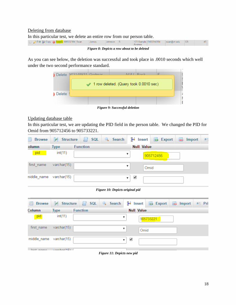
Deleting from database
In this particular test, we delete an entire row from our person table.
Figure 8: Depicts a row about to be deleted
As you can see below, the deletion was successful and took place in .0010 seconds which well
under the two second performance standard.
Figure 9: Successful deletion
Updating database table
In this particular test, we are updating the PID field in the person table. We changed the PID for
Omid from 905712456 to 905733221.
Figure 10: Depicts original pid
Figure 11: Depicts new pid
19
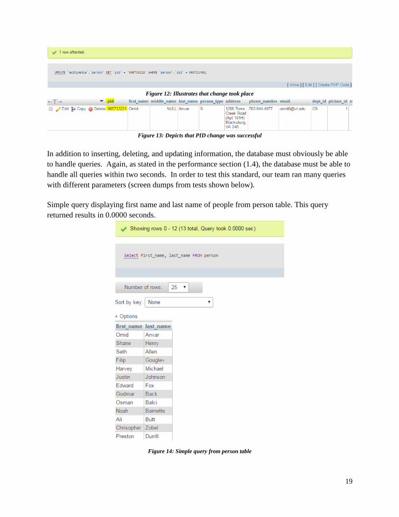
Figure 12: Illustrates that change took place
Figure 13: Depicts that PID change was successful
In addition to inserting, deleting, and updating information, the database must obviously be able
to handle queries. Again, as stated in the performance section (1.4), the database must be able to
handle all queries within two seconds. In order to test this standard, our team ran many queries
with different parameters (screen dumps from tests shown below).
Simple query displaying first name and last name of people from person table. This query
returned results in 0.0000 seconds.
Figure 14: Simple query from person table
20
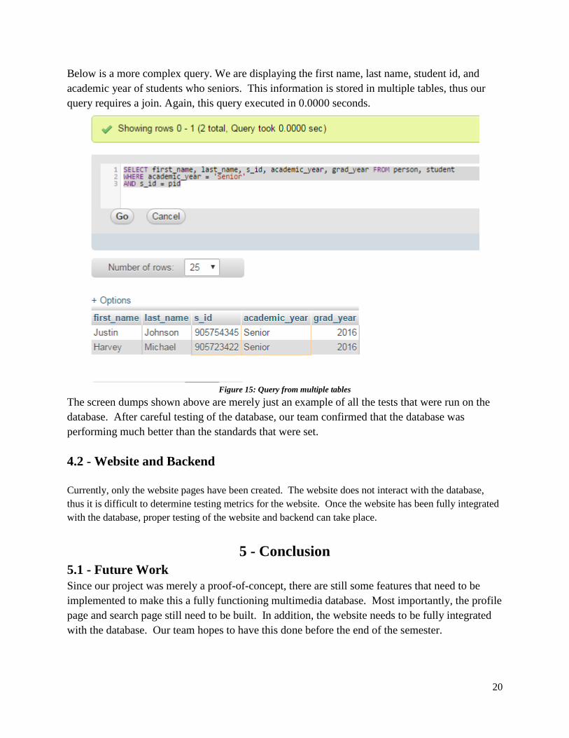
Below is a more complex query. We are displaying the first name, last name, student id, and
academic year of students who seniors. This information is stored in multiple tables, thus our
query requires a join. Again, this query executed in 0.0000 seconds.
Figure 15: Query from multiple tables
The screen dumps shown above are merely just an example of all the tests that were run on the
database. After careful testing of the database, our team confirmed that the database was
performing much better than the standards that were set.
4.2 - Website and Backend
Currently, only the website pages have been created. The website does not interact with the database,
thus it is difficult to determine testing metrics for the website. Once the website has been fully integrated
with the database, proper testing of the website and backend can take place.
5 - Conclusion
5.1 - Future Work
Since our project was merely a proof-of-concept, there are still some features that need to be
implemented to make this a fully functioning multimedia database. Most importantly, the profile
page and search page still need to be built. In addition, the website needs to be fully integrated
with the database. Our team hopes to have this done before the end of the semester.
21
After speaking to a few potential students about continuing work on the project after we
graduate, our team decided on Kasra Eslami, a sophomore Virginia Tech Computer Science
student. Our team is confident that Kasra’s strong technical ability and passion will allow our
project to continue in the right direction. Kasra can be contacted at [email protected].
In regards to the database, future projects should include a database backup system. This system
will periodically take backups of the data and store it in an external location. Through this
practice, if the database was to unexpectedly crash losing all its data, the backup can be deployed
to roll back the database to a previous state.
In addition to keeping backups, the database should also keep a transaction log. The transaction
log will keep records of any modifications (i.e. insertions, deletion, and updates) made to the
database. A transaction log can prove to be useful if the database administrator wants to see who
made a certain change. Furthermore, the transaction log must also take backups periodically.
In our project, a user’s password was stored as plaintext in the database; however, this is poor
practice. A proper method of storing a password is to hash and salt a user’s password before
storing it in the database. The password must be hashed using Java’s PBKDF2 library and a
randomly generated 64-bit salt (Gupta). Then the hashed password is stored in the database. On
sign-in the stored hashed password will be checked against the entered password to authenticate
the user. We hope that in future iterations of the project that this security measure will be
invoked.
The application is currently being run locally on our machines. In the mere future, we hope that
the application will be deployed on a server. Our team has made attempts to contact university
officials about the possibility of finding a server to run the application; however, all our attempts
proved futile. Whoever takes over the project from here must be responsible for finding a stable
server.
Lastly, the application must be tested by outside users to prove that it can handle large amounts
of traffic. Since the goal is allow hundreds of students to be able to upload to the database, we
want to ensure that application will not crash.
5.2 - Lessons Learned
The biggest lesson our team learned is that if a team is going to propose their own project to
work on (as we did), then the team members need to be technically strong to be able to complete
the project without constant struggling. In addition, if a team wants to propose a project, they
must have a detailed understanding of what they are proposing and a concrete plan on how to
complete the project. Other useful lessons we learned is that it is incredibly important to have a
timeline of when certain phases are expected to be completed. This will allow for the project to
be completed in a timely matter without constant headaches.
22
5.3 - Acknowledgements
Our team would like to take the time to thank all the people who helped make this project
possible. First, we would like to thank Dr. Christopher Zobel for agreeing to be our project’s
client and for taking the time to meet with us whenever necessary to help guide the project’s
direction. In addition, we would like to acknowledge the help of Dr. Edward Fox and graduate
teaching assistant Yilong Jin for meeting with us on a weekly basis to help with the process of
writing a proper technical report.
23
Appendix
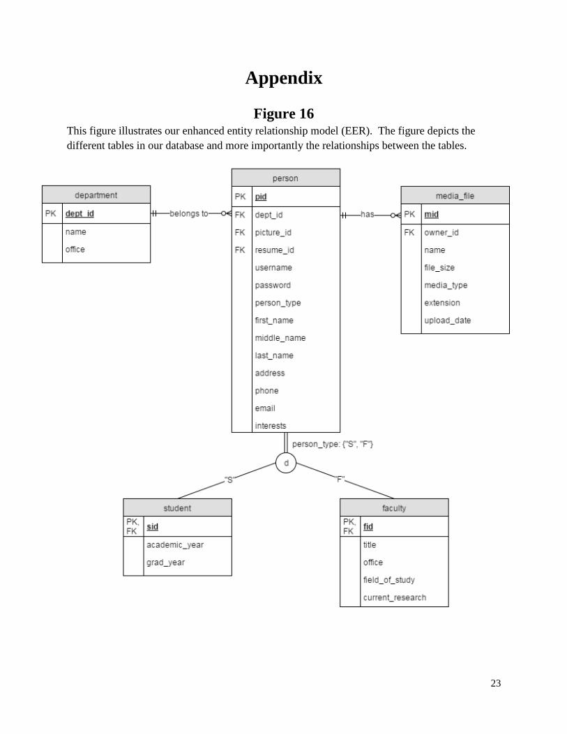
Figure 16 This figure illustrates our enhanced entity relationship model (EER). The figure depicts the
different tables in our database and more importantly the relationships between the tables.
24
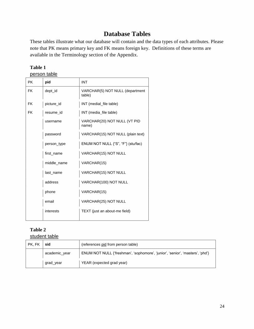
Database Tables These tables illustrate what our database will contain and the data types of each attributes. Please
note that PK means primary key and FK means foreign key. Definitions of these terms are
available in the Terminology section of the Appendix.
Table 1
person table
PK pid INT
FK dept_id VARCHAR(5) NOT NULL (department table)
FK picture_id INT (medial_file table)
FK resume_id INT (media_file table)
username VARCHAR(20) NOT NULL (VT PID name)
password VARCHAR(15) NOT NULL (plain text)
person_type ENUM NOT NULL {“S”, “F”} (stu/fac)
first_name VARCHAR(15) NOT NULL
middle_name VARCHAR(15)
last_name VARCHAR(15) NOT NULL
address VARCHAR(100) NOT NULL
phone VARCHAR(15)
email VARCHAR(25) NOT NULL
interests TEXT (just an about-me field)
Table 2
student table
PK, FK sid (references pid from person table)
academic_year ENUM NOT NULL {‘freshman’, ‘sophomore’, ‘junior’, ‘senior’, ‘masters’, ‘phd’}
grad_year YEAR (expected grad year)
25
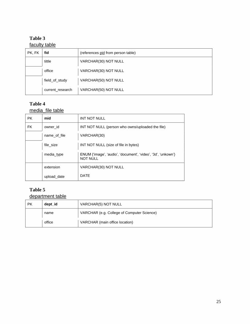
Table 3
faculty table
PK, FK fid (references pid from person table)
tittle VARCHAR(30) NOT NULL
office VARCHAR(30) NOT NULL
field_of_study VARCHAR(50) NOT NULL
current_research VARCHAR(50) NOT NULL
Table 4
media_file table
PK mid INT NOT NULL
FK owner_id INT NOT NULL (person who owns/uploaded the file)
name_of_file VARCHAR(30)
file_size INT NOT NULL (size of file in bytes)
media_type ENUM {‘image’, ‘audio’, ‘document’, ‘video’, ‘3d’, ‘unkown’} NOT NULL
extension upload_date
VARCHAR(30) NOT NULL DATE
Table 5
department table
PK dept_id VARCHAR(5) NOT NULL
name VARCHAR (e.g. College of Computer Science)
office VARCHAR (main office location)
26
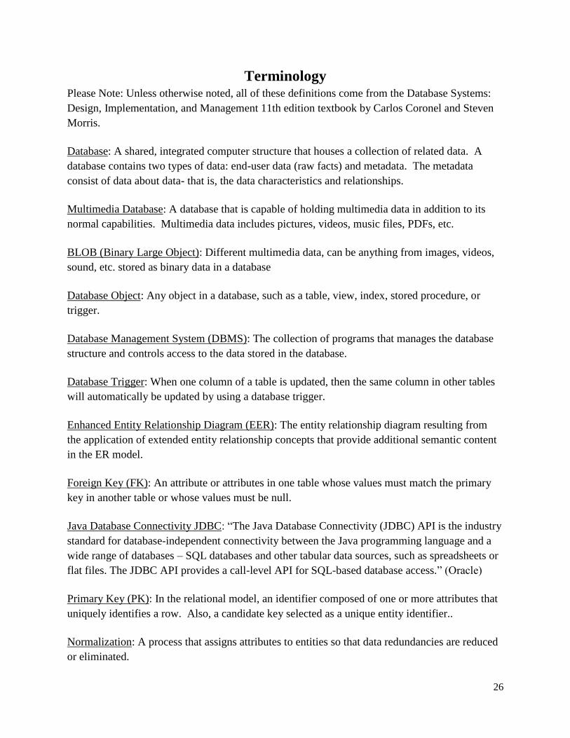
Terminology Please Note: Unless otherwise noted, all of these definitions come from the Database Systems:
Design, Implementation, and Management 11th edition textbook by Carlos Coronel and Steven
Morris.
Database: A shared, integrated computer structure that houses a collection of related data. A
database contains two types of data: end-user data (raw facts) and metadata. The metadata
consist of data about data- that is, the data characteristics and relationships.
Multimedia Database: A database that is capable of holding multimedia data in addition to its
normal capabilities. Multimedia data includes pictures, videos, music files, PDFs, etc.
BLOB (Binary Large Object): Different multimedia data, can be anything from images, videos,
sound, etc. stored as binary data in a database
Database Object: Any object in a database, such as a table, view, index, stored procedure, or
trigger.
Database Management System (DBMS): The collection of programs that manages the database
structure and controls access to the data stored in the database.
Database Trigger: When one column of a table is updated, then the same column in other tables
will automatically be updated by using a database trigger.
Enhanced Entity Relationship Diagram (EER): The entity relationship diagram resulting from
the application of extended entity relationship concepts that provide additional semantic content
in the ER model.
Foreign Key (FK): An attribute or attributes in one table whose values must match the primary
key in another table or whose values must be null.
Java Database Connectivity JDBC: “The Java Database Connectivity (JDBC) API is the industry
standard for database-independent connectivity between the Java programming language and a
wide range of databases – SQL databases and other tabular data sources, such as spreadsheets or
flat files. The JDBC API provides a call-level API for SQL-based database access.” (Oracle)
Primary Key (PK): In the relational model, an identifier composed of one or more attributes that
uniquely identifies a row. Also, a candidate key selected as a unique entity identifier..
Normalization: A process that assigns attributes to entities so that data redundancies are reduced
or eliminated.
27
Key Attributes: The attributes that form a primary key.
One-to-One Relationship: Associations among two or more entities that are used by data models.
In a 1:1 relationship, one entity instance is associated with only one instance of the related entity.
One-to-Many Relationship: Associations among two or more entities that are used by data
models. In a 1:M relationship, one entity instance is associated with many instances of the
related entity.
Structured Query Language (SQL): A powerful and flexible relational database language
composed of commands that enable users to create database and table structures, perform various
types of data manipulation and data administration, and query the database to extract useful
information.
Superkey: An attribute or attributes that uniquely identify each entity in a table.
Table: A matrix composed of intersecting rows (entities) and columns (attributes) that represent
an entity set in the relational model. Also called a relation.

28
References
Balci, Osman, and Kyle Schutt. "Cloud Software Development Platforms: A Comparative
Overview." CS4984 Cloud Software Development. 20 Oct. 2015. Web. 25 Mar. 2016.
<http://manta.cs.vt.edu/cs4984/StudentsOnly/StudentsOnly.html >
"Blob Storage in InnoDB." Percona. N.p., 09 Feb. 2010. Web. 25 Mar. 2016.
<https://www.percona.com/blog/2010/02/09/blob-storage-in-innodb/>
Coronel, Carlos, and Steven Morris. Database Systems: Design, Implementation, and
Management 11th Edition. Stamford, CT: Cengage Learning. 2015. Print.
Gupta, Lokesh. "Generate Secure Password Hash: MD5, SHA, PBKDF2, BCrypt Examples."
HowToDoInJava. HowToDoInjava.com, 22 July 2013. Web. 27 Mar. 2016. <
http://howtodoinjava.com/security/how-to-generate-secure-password-hash-md5-sha-
pbkdf2-bcrypt-examples/>
Heffelfinger, David R. Java EE 7 Development with NetBeans 8. Birmingham: Packt Limited,
2015. Print.
Oracle. "Java SE Technologies - Database." Java SE Technologies - Database. Oracle. Web. 27
Mar. 2016. <http://www.oracle.com/technetwork/java/javase/tech/index-jsp-
136101.html>
"What Is Difference between Storing Data in a Blob, vs. Storing a Pointer to a File?" Stack
Overflow. Web. 28 Mar. 2016. <http://stackoverflow.com/questions/13435187/what-is-
difference-between-storing-data-in-a-blob-vs-storing-a-pointer-to-a-fi>