Embed Size (px)
Citation preview
Computers & Industrial Engineering 64 (2013) 537–544
Contents lists available at SciVerse ScienceDirect
Computers & Industrial Engineering
journal homepage: www.elsevier .com/ locate/caie
Multiobjective layout optimization of robotic cellular manufacturingsystems
0360-8352/$ - see front matter � 2012 Elsevier Ltd. All rights reserved.http://dx.doi.org/10.1016/j.cie.2012.12.003
⇑ Corresponding author. Tel.: +81 75 753 5198, fax: +81 75 753 5857.E-mail address: [email protected] (K. Izui).
Kazuhiro Izui a,⇑, Yutaka Murakumo a, Issei Suemitsu a, Shinji Nishiwaki a, Akio Noda b, Tatsuya Nagatani b
a Department of Mechanical Engineering and Science, Kyoto University, Yoshida-honmachi, Sakyo-ku, Kyoto 606-8501, Japanb Mitsubishi Electric Corporation, Tsukaguchi-honmachi 8-1-1, Amagasaki, Hyogo, Japan
a r t i c l e i n f o a b s t r a c t
Article history:Received 9 June 2012Received in revised form 4 December 2012Accepted 5 December 2012Available online 14 December 2012
Keywords:Robot cellAssembly layoutDesign optimizationGenetic algorithmSequence-pair representation
This paper proposes a multiobjective layout optimization method for the conceptual design of robot cel-lular manufacturing systems. Robot cellular manufacturing systems utilize one or more flexible robotswhich can carry out a large number of operations, and can conduct flexible assemble processes. The lay-out design stage of such manufacturing systems is especially important since fundamental performancesof the manufacturing system under consideration are determined at this stage. In this paper, the designcriteria for robot cellular manufacturing system layout designs are clarified, and objective functions areformulated. Next, layout design candidates are represented using a sequence-pair scheme to avoid inter-ference between assembly system components, and the use of dummy components is proposed to rep-resent layout areas where components are sparse. A multiobjective genetic algorithm is then used toobtain Pareto optimal solutions for the layout optimization problems. Finally, several numerical exam-ples are provided to illustrate the effectiveness and usefulness of the proposed method.
� 2012 Elsevier Ltd. All rights reserved.
1. Introduction
Robotic cellular manufacturing systems (RCMSs) are a new typeof manufacturing system in which one or more flexible robotscarry out a large number of assembly operations that would beperformed by human workers in conventional cellular manufactur-ing systems. When compared with conventional human cellularmanufacturing systems, RCMS are seen to offer similar advantages,such as reduction of material flow distances and local inventory.However, although reduced operation costs due to automation ofthe manufacturing systems can be achieved by introducing RCMS,the design of assembly operations and robot teaching can becomequite awkward and time-consuming when launching new manu-facturing systems.
As with all manufacturing systems, the layout design stage,where fundamental performances of the manufacturing systemunder consideration are determined, is one of the most importantstages when building efficient RCMS. The layout design stage is anupstream stage of the manufacturing system design process, anddecisions made then exert considerable influence on the detaileddesign of robot motion planning and the teaching process. There-fore, skillful decision-making during the layout design stage isessential for minimizing design changes during the detailed designstage and teaching process, and to enhance the efficiency and reli-ability of the manufacturing systems when deployed.
With this background in mind, optimization techniques havebeen applied to assist the layout design of RCMS (Tay & Ngoi,1996; Barral, Perrin, Dombre, & Liegeois, 2001). Unfortunately,these methods require explicit constraint handling regarding com-ponent overlapping, since component coordinates are handled asdesign variables, and this implementation obstructs global search-ing of the solution space.
Layout problems have raised important issues in many researchfields, such as printed circuit board problems (Shahookar &Mazumder, 1991) and facility layout problems (Drira, Pierreval, &Gabouj, 2007; Gen, Lin, & Zhang, 2009), and effective optimizationmethods which can avoid the handling of overlapping constraintshave been reported. For example, Kleinhans, Sigl, Johannes, andAntreich (1991), Quinn and Breuer (1979), and Dunlop and Kerni-ghan (1985) proposed multi-step optimization techniques. In thesemethods, several component overlaps are allowed in the first opti-mization step, and such overlaps are subsequently resolved. How-ever, the overlap resolution step may degrade solutions andoptimization computational requirements tend to be significant.Tree-structure representation techniques (Dai & Kuh, 1987; Chen& Chang, 2006) are very effective for avoiding overlaps, but thesemethods can be applied only to partitioning problems. Birgin andLobato (2010) proposed a rectangular packing technique whichavoids overlapping, however this technique assumes that all rect-angles have an identical shape.
On the other hand, sequence-pair representation can avoidoverlaps among components and allow various sizes of rectangles(Murata, Fujiyoshi, Nakatake, & Kajitani, 1996). Several papers
538 K. Izui et al. / Computers & Industrial Engineering 64 (2013) 537–544
report that this representation enables very effective layoutoptimization in packing-type problems (Drakidis, Mack, & Massara,2006) and facility layout problems (Meller, Chen, & Sherali, 2007;Liu & Meller, 2007). Therefore, this paper proposes a new layoutoptimization method for RCMS that uses sequence-pair represen-tation. The major difference between RCMS layout problems andconventional packing-type or general facility layout problems isthat the minimization of packing area is the most important crite-rion in the former, but optimal spacing among distributed compo-nents is paramount in the latter. This paper proposes a dummycomponent approach to provide such spacing between a single ro-bot and other components. In the following section, the designrequirements for the RCMS are clarified first and then quantitativedesign criteria are formulated. Next, a sequence-pair representa-tion scheme for layout optimization is introduced and an optimiza-tion procedure is proposed. Finally, the proposed optimizationmethod is applied to numerical examples to demonstrate the effec-tiveness of the proposed method.
2. Criteria for layout design
2.1. Layout design problem
The most important consideration when developing new man-ufacturing systems is operation time, and Tay and Ngoi (1996) andBarral et al. (2001) proposed single-objective layout optimizationalgorithms for minimizing RCMS operation time. However, duringthe layout design stage, multiple design requirements must beconsidered, so single-objective optimization approaches are insuf-ficient in many RCMS design cases. Feasibility verification ofassembly tasks is an essential process in the RCMS layout designstage. Another highly important consideration is the minimizationof layout area, to enhance the efficiency of factory-level layouts.The quantitative criteria for these requirements are discussed inthe following subsections.
2.2. Operation time
Consider an RCMS composed of part feeders, an assembly tableand an assembly robot. The total operation time of the RCMS canbe classified into assembly time and robot motion time. Robot mo-tion time is time spent moving the robot end-effector to retrieveassemblies or assembly parts and move them to another location,and the manufacturing system layout greatly influences thesedurations, which must be minimized.
However, precise evaluation of robot motion time is almostimpossible in the layout design stage where no detailed motiontrajectory information is given. Therefore, we evaluate robot mo-tion time based on the rotational angle of robot arm joints betweenstarting and terminal points for each robot motion. Since the max-imum angular velocity value of each assembly robot joint is usuallygiven at the layout design stage, we approximately calculate therobot motion time by assuming that the joint motion has a uniformvelocity based on its maximum angular velocity. Hence, the robotmotion time Ti
k of the kth joint performing the ith motion is givenin the following equation:
Tik ¼
�qik
�� ��xk
ð1Þ
where xk indicates the maximum angular velocity of the kth jointand �qi
k is the angle through which the kth joint moves during theith motion.
We assume that all joints can simultaneously have their anglechanged, and the ith motion time is evaluated using the maximumjoint motion time as follows:
Ti ¼ maxk
�qik
�� ��xk
" #ð2Þ
Therefore, the total robot motion time for one assembly cycle T isevaluated as follows:
T ¼Xh
i¼1
Ti ð3Þ
where h is the number of robot motions in one assembly cycle.
2.3. Feasibility of assembly tasks
In RCMS, robots must conduct skilled assembly tasks. Thismeans that having a robot arm reach appropriate task positionsis only one of the necessary conditions required to conduct anassembly task, but not a sufficient condition alone. If the robot pos-ture at a task position is close to a singular point, the assembly taskmay not be successfully completed. Therefore, consideration ofhow to avoid such singular points at the layout design stage isessential for obtaining a feasible assembly process.
In order to avoid singular points, evaluation of kinematicmanipulability (Yoshikawa, 1985) is beneficial. Manipulability isa quantitative measure of the manipulating ability of robot armsthat can be calculated based on the relationship among the posi-tion of the end-effector and joint vectors.
Consider a manufacturing system using an n degree-of-freedomassembly robot which conducts tasks at h positions, with its kthjoint variable at the jth task position denoted as qj
k, with joint vec-tor qj. The robot posture vector rj at the jth position (j = 1, 2, . . ., h)isdefined as follows:
qj ¼ ½qj1; q
j2; . . . ; qj
n�T ðj ¼ 1;2; . . . ;hÞ ð4Þ
rj ¼ ½rj1; r
j2; . . . ; rj
m�T ð5Þ
where m is the number of dimensions needed to represent the posi-tion and angle of the end-effector. Then, the relationship between rj
and qj is represented as follows:
rj ¼ f ðqjÞ ð6Þ
In the following discussion, the notation of task position j is ig-nored for simplicity. By the chain-rule, velocity vector vð¼ _rÞ is ob-tained as,
v ¼ JðqÞ _q ð7Þ
where _q indicates the joint velocity vector and JðqÞ is the Jacobian.Consider subset Sv of the realizable velocity v such that the cor-
responding joint velocity _q satisfies
_q ¼ _q21 þ _q2
2 þ � � � þ _q2n
� �1=26 1 ð8Þ
This subset is an m dimensional Euclidean ellipse and its volume Vis
V ¼ cmw ð9Þ
where the coefficient cm is
cm ¼ð2pÞ
m2
2�4�6���ðm�2Þ�m if m is an even
2ð2pÞm�1
2
1�3�5���ðm�2Þ�m if m is an odd
8><>: ð10Þ
Since cm is a constant value, the volume of the ellipse can beevaluated by w which is referred to as a manipulability measure(Yoshikawa, 1985). The larger the manipulability w, the fasterthe end-effector can move in any direction, implying that largermanipulability values of w indicate that the robot can conduct morecomplicated tasks. Therefore, we calculate the value of w here to
e
b
c
f
a d
Layout area: S
Fig. 1. Layout area.
Fig. 2. Relative arrangement.
K. Izui et al. / Computers & Industrial Engineering 64 (2013) 537–544 539
evaluate the feasibility of the assembly tasks. In the case of non-redundant robots, w is calculated as follows:
w ¼ jdetJðqÞj ð11Þ
Therefore, using the superscript of task position j, the overallfeasibility of assembly task W in a robotic cellular manufacturingsystem is evaluated using the weighted summation of manipula-bility values at h task positions, as follows:
W ¼Xh
j¼1
ajwj ð12Þ
where wj is the manipulability at the jth task position and aj denotesa weighting coefficient.
2.4. Layout area
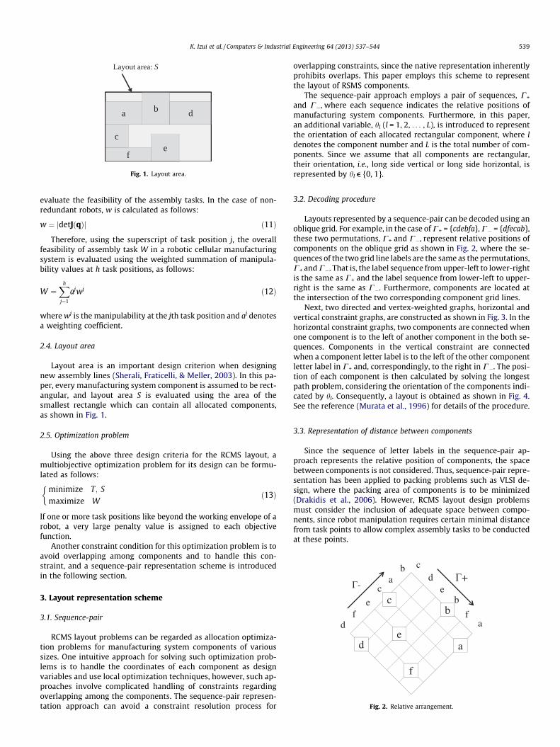
Layout area is an important design criterion when designingnew assembly lines (Sherali, Fraticelli, & Meller, 2003). In this pa-per, every manufacturing system component is assumed to be rect-angular, and layout area S is evaluated using the area of thesmallest rectangle which can contain all allocated components,as shown in Fig. 1.
2.5. Optimization problem
Using the above three design criteria for the RCMS layout, amultiobjective optimization problem for its design can be formu-lated as follows:
minimize T; S
maximize W
�ð13Þ
If one or more task positions like beyond the working envelope of arobot, a very large penalty value is assigned to each objectivefunction.
Another constraint condition for this optimization problem is toavoid overlapping among components and to handle this con-straint, and a sequence-pair representation scheme is introducedin the following section.
3. Layout representation scheme
3.1. Sequence-pair
RCMS layout problems can be regarded as allocation optimiza-tion problems for manufacturing system components of varioussizes. One intuitive approach for solving such optimization prob-lems is to handle the coordinates of each component as designvariables and use local optimization techniques, however, such ap-proaches involve complicated handling of constraints regardingoverlapping among the components. The sequence-pair represen-tation approach can avoid a constraint resolution process for
overlapping constraints, since the native representation inherentlyprohibits overlaps. This paper employs this scheme to representthe layout of RSMS components.
The sequence-pair approach employs a pair of sequences, C+
and C�, where each sequence indicates the relative positions ofmanufacturing system components. Furthermore, in this paper,an additional variable, hl (l = 1, 2, . . . , L), is introduced to representthe orientation of each allocated rectangular component, where ldenotes the component number and L is the total number of com-ponents. Since we assume that all components are rectangular,their orientation, i.e., long side vertical or long side horizontal, isrepresented by hl e {0, 1}.
3.2. Decoding procedure
Layouts represented by a sequence-pair can be decoded using anoblique grid. For example, in the case of C+ = {cdebfa}, C� = {dfecab},these two permutations, C+ and C�, represent relative positions ofcomponents on the oblique grid as shown in Fig. 2, where the se-quences of the two grid line labels are the same as the permutations,C+ and C�. That is, the label sequence from upper-left to lower-rightis the same as C+ and the label sequence from lower-left to upper-right is the same as C�. Furthermore, components are located atthe intersection of the two corresponding component grid lines.
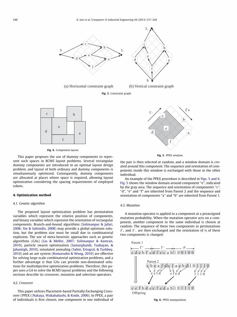
Next, two directed and vertex-weighted graphs, horizontal andvertical constraint graphs, are constructed as shown in Fig. 3. In thehorizontal constraint graphs, two components are connected whenone component is to the left of another component in the both se-quences. Components in the vertical constraint are connectedwhen a component letter label is to the left of the other componentletter label in C+ and, correspondingly, to the right in C�. The posi-tion of each component is then calculated by solving the longestpath problem, considering the orientation of the components indi-cated by hl. Consequently, a layout is obtained as shown in Fig. 4.See the reference (Murata et al., 1996) for details of the procedure.
3.3. Representation of distance between components
Since the sequence of letter labels in the sequence-pair ap-proach represents the relative position of components, the spacebetween components is not considered. Thus, sequence-pair repre-sentation has been applied to packing problems such as VLSI de-sign, where the packing area of components is to be minimized(Drakidis et al., 2006). However, RCMS layout design problemsmust consider the inclusion of adequate space between compo-nents, since robot manipulation requires certain minimal distancefrom task points to allow complex assembly tasks to be conductedat these points.
c
f
b
d ae
LS
c
f
b
d ae
S
L
(a) Horizontal constraint graph (b) Vertical constraint graph
Fig. 3. Constraint graph.
d
b
f
c
e
a
Fig. 4. Component layout.
Fig. 5. PPEX window.
Fig. 6. PPEX manipulation.
540 K. Izui et al. / Computers & Industrial Engineering 64 (2013) 537–544
This paper proposes the use of dummy components to repre-sent such spaces in RCMS layout problems. Several rectangulardummy components are introduced in an optimal layout designproblem, and layout of both ordinary and dummy components issimultaneously optimized. Consequently, dummy componentsare allocated at places where space is required, allowing layoutoptimization considering the spacing requirements of employedrobots.
4. Optimization method
4.1. Genetic algorithm
The proposed layout optimization problem has permutationvariables which represent the relative position of components,and binary variables which represent the orientation of rectangularcomponents. Branch-and-bound algorithms (Solimanpur & Jafari,2008; Xie & Sahinidis, 2008) may provide a global optimum solu-tion, but the problem size must be small due to combinatorialexplosion. The use of meta-heuristic approaches such as geneticalgorithms (GAs) (Liu & Meller, 2007; Solimanpur & Kamran,2010), particle swarm optimization (Samarghandi, Taabayan, &Jahantigh, 2010), simulated annealing (Sahin, Ertogral, & Turkbey,2010) and an ant system (Komarudin & Wong, 2010) are effectivefor solving large-scale combinatorial optimization problems, and afurther advantage is that GAs can provide non-dominated solu-tions for multiobjective optimization problems. Therefore, this pa-per uses a GA to solve the RCMS layout problems and the followingsections describe its crossover, mutation and selection operators.
4.2. Crossover
This paper utilizes Placement-based Partially Exchanging Cross-over (PPEX) (Nakaya, Wakabahashi, & Koide, 2000). In PPEX, a pairof individuals is first chosen, one component in one individual of
the pair is then selected at random, and a window domain is cre-ated around this component. The sequence and orientation of com-ponents inside this window is exchanged with those in the otherindividual.
An example of the PPEX procedure is described in Figs. 5 and 6.Fig. 5 shows the window domain around component ‘‘e’’, indicatedby the gray area. The sequence and orientation of components ‘‘c’’,‘‘d’’, ‘‘e’’ and ‘‘f’’ are inherited from Parent 2 and the sequence andorientation of components ‘‘a’’ and ‘‘b’’ are inherited from Parent 1.
4.3. Mutation
A mutation operator is applied to a component at a preassignedmutation probability. When the mutation operator acts on a com-ponent, another component in the same individual is chosen atrandom. The sequence of these two components in permutationsC+ and C� are then exchanged and the orientation of hl of thesetwo components is changed.
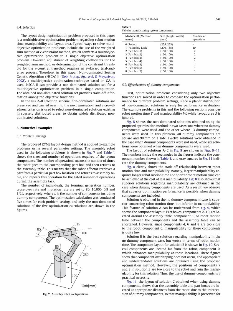
Table 1Cellular manufacturing system components.
Machine ID (Machinename)
Size (height, width)(mm)
Number ofoperations
0 (Robot) (255, 255) –1 (Assembly Table) (270, 188) 102 (Part box 1) (150, 100) 23 (Part box 2) (150, 100) 24 (Part box 3) (150, 100) 25 (Part box 4) (150, 100) 16 (Part box 5) (150, 100) 17 (Part box 6) (150, 100) 18 (Part box 7) (150, 100) 1
K. Izui et al. / Computers & Industrial Engineering 64 (2013) 537–544 541
4.4. Selection
The layout design optimization problem proposed in this paperis a multiobjective optimization problem regarding robot motiontime, manipulability and layout area. Typical ways to solve multi-objective optimization problems include the use of the weightedsum method or �-constraint method, which converts a multiobjec-tive optimization problem to a single objective optimizationproblem. However, adjustment of weighting coefficients for theweighted sum method, or determination of the constraint thresh-old for the �-constraint method requires an awkward trial-and-error process. Therefore, in this paper, Non-dominated SortingGenetic Algorithm (NSGA)-II (Deb, Pratap, Agarwal, & Meyarivan,2002), a multiobjective optimization technique based on GA, isused. NSGA-II can provide a non-dominated solution set for amultiobjective optimization problem in a single computation.The obtained non-dominated solution set provides trade-off infor-mation among the objective functions.
In the NSGA-II selection scheme, non-dominated solutions arepreserved and carried over into the next generation, and a crowd-edness criterion is used to select non-dominated solutions existingin sparsely distributed areas, to obtain widely distributed non-dominated solutions.
5. Numerical examples
5.1. Problem settings
The proposed RCMS layout design method is applied to exampleproblems using several parameter settings. The assembly robotused in the following problems is shown in Fig. 7 and Table 1shows the sizes and number of operations required of the layoutcomponents. The number of operations means the number of timesthe robot goes to the corresponding part box and then returns tothe assembly table. This means that the robot effector retrieves apart from a particular part box location and returns to assembly ta-ble, and repeats this operation for the listed number of operationsduring the assembly task.
The number of individuals, the terminal generation number,cross-over rate and mutation rate are set to 80, 10,000, 0.8 and1/2L, respectively, where L is the number of components includingdummy components. The optimization calculation was conductedfive times for each problem setting, and only the non-dominatedsolutions of the five optimization calculations are shown in thefigures.
280
350
85
100
315
Unit[mm]
85
Fig. 7. Assembly robot configurations.
5.2. Effectiveness of dummy components
First, optimization problems considering only two objectivefunctions are solved in order to compare the optimization perfor-mance for different problem settings, since a planer distributionof non-dominated solutions is easy for performance evaluation.The example problems in this and the following sections considerrobot motion time T and manipulability W, while layout area S isignored.
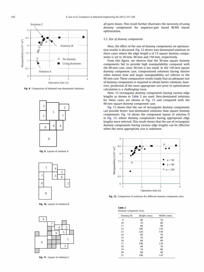
Fig. 8 shows the non-dominated solutions obtained using theproposed optimization method in two cases, one where no dummycomponents were used and the other where 13 dummy compo-nents were used. In this problem, all dummy components aresquare and 90 mm on a side. Twelve solutions were obtained inthe case when dummy components were not used, while six solu-tions were obtained when dummy components were used.
The layout of solutions A–C in Fig. 8 are shown in Figs. 9–11.The numbers inside the rectangles in the figures indicate the com-ponent number shown in Table 1, and gray squares in Fig. 11 indi-cate the dummy components.
Fig. 8 clearly shows the trade-off relationship between robotmotion time and manipulability, namely, larger manipulability re-quires longer robot motion time and shorter robot motion time canbe achieved at the cost of less manipulability. Fig. 8 also shows thatsuperior solutions regarding manipulability are obtained in thecase when dummy components are used. As a result, we observethat superior optimization performance is possible when dummycomponents are included.
Solution A obtained in the no dummy component case is supe-rior concerning robot motion time, but inferior in manipulability.This feature of solution A can be understood from Fig. 9, whichshows the component layout. Part boxes, components 2–10, are lo-cated around the assembly table, component 1, so robot motiontime between the components and the assembly table can beshortened. However, since components 4, 6 and 8 are too closeto the robot, component 0, manipulability for these componentsis quite low.
Solution B is the best solution regarding manipulability in theno dummy component case, but worse in terms of robot motiontime. The component layout for solution B is shown in Fig. 10. Sev-eral components are located far from the robot, component 0,which enhances manipulability at these locations. These figuresshow that component overlapping does not occur, and appropriateand understandable solutions are obtained using the proposedoptimization method. However, the positions of components 7and 8 in solution B are too close to the robot and ruin the manip-ulability for this solution. Thus, the use of dummy components is apractical necessity.
Fig. 11, the layout of solution C obtained when using dummycomponents, shows that the assembly table and part boxes are lo-cated at appropriate distances from the robot, due to the interces-sion of dummy components, so that manipulability is preserved for
6
6.5
7
7.5
8
8.5
9
1 2 3 4
No dummy
Using dummies
Solution C
Solution A
Man
ipul
abili
ty [
x10-1
m3 ]
Operation time [s]
Solution B
Fig. 8. Comparison of obtained non-dominated solutions.
0
12
3
4
5
6
7
8
Fig. 9. Layout of solution A.
0
1
2
34
5 67
8
Fig. 10. Layout of solution B.
01
2
3
4
5
6
7
8
Fig. 11. Layout of solution C.
542 K. Izui et al. / Computers & Industrial Engineering 64 (2013) 537–544
all parts boxes. This result further illustrates the necessity of usingdummy components for sequence-pair based RCMS layoutoptimization.
5.3. Size of dummy components
Next, the effect of the size of dummy components on optimiza-tion results is discussed. Fig. 12 shows non-dominated solutions inthree cases where the edge length a of 13 square dummy compo-nents is set to 30 mm, 90 mm and 150 mm, respectively.
From this figure, we observe that the 30 mm square dummycomponents fail to provide high manipulability compared withthe 90 mm case, since 30 mm is too small. In the 150 mm squaredummy component case, compromised solutions having shorterrobot motion time and larger manipulability are inferior to the90 mm case. These comparative results imply that an adequate sizeof dummy components is required to obtain better solutions, how-ever, prediction of the most appropriate size prior to optimizationcalculation is a challenging issue.
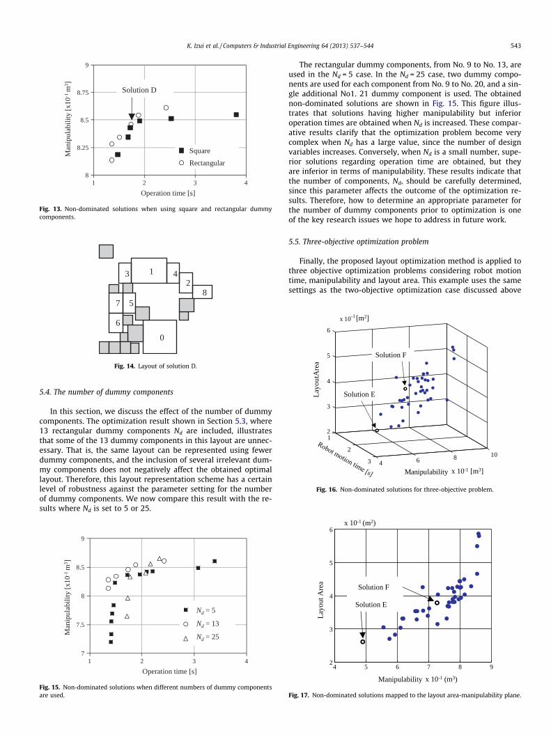
Next, 13 rectangular dummy components having various edgelengths as shown in Table 2 are used. Non-dominated solutionsfor these cases are shown in Fig. 13 and compared with the90 mm square dummy component case.
Fig. 13 shows that the use of rectangular dummy componentscan provide better non-dominated solutions than square dummycomponents. Fig. 14 shows the component layout of solution Din Fig. 13, where dummy components having appropriate edgelengths were selected. This result shows that the use of rectangulardummy components having various edge lengths can be effectivewhen the most appropriate size is unknown.
6
6.5
7
7.5
8
8.5
9
1 2 3 4
Man
ipul
abil
ity
[x10
-1 m
3 ]
Operation time [s]
a = 30
a = 150
a = 90
Fig. 12. Comparison of solutions for different dummy component sizes.
Table 2Dummy component sizes.
Dummy ID Height (mm) Width (mm)
9 60 7010 70 8011 80 9012 100 11013 120 13014 60 7015 70 8016 80 9017 100 11018 60 7019 70 8020 80 9021 100 110
0
12
3 4
5
6
78
Fig. 14. Layout of solution D.
8
8.25
8.5
8.75
9
1 2 3 4
Square
Rectangular
Man
ipul
abili
ty [
x10-1
m3 ]
Operation time [s]
Solution D
Fig. 13. Non-dominated solutions when using square and rectangular dummycomponents.
1
2
3 4 6 8 10
2
3
4
5
6
x 10
Manipulability
Lay
outA
rea
-1 [m2]
x 10-1 [m3]
Solution E
Solution F
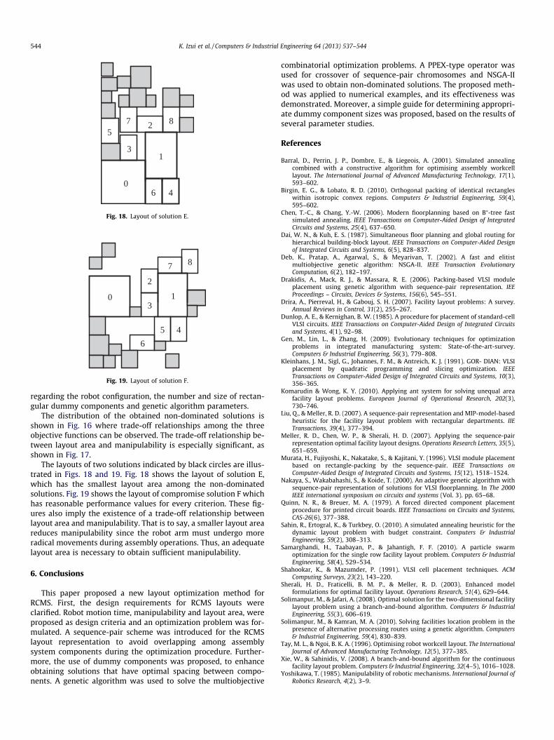
Fig. 16. Non-dominated solutions for three-objective problem.
K. Izui et al. / Computers & Industrial Engineering 64 (2013) 537–544 543
5.4. The number of dummy components
In this section, we discuss the effect of the number of dummycomponents. The optimization result shown in Section 5.3, where13 rectangular dummy components Nd are included, illustratesthat some of the 13 dummy components in this layout are unnec-essary. That is, the same layout can be represented using fewerdummy components, and the inclusion of several irrelevant dum-my components does not negatively affect the obtained optimallayout. Therefore, this layout representation scheme has a certainlevel of robustness against the parameter setting for the numberof dummy components. We now compare this result with the re-sults where Nd is set to 5 or 25.
7
7.5
8
8.5
9
1 2 3 4
Man
ipul
abili
ty [
x10-1
m3 ]
Operation time [s]
Nd = 5
Nd = 13
Nd = 25
Fig. 15. Non-dominated solutions when different numbers of dummy componentsare used.
The rectangular dummy components, from No. 9 to No. 13, areused in the Nd = 5 case. In the Nd = 25 case, two dummy compo-nents are used for each component from No. 9 to No. 20, and a sin-gle additional No1. 21 dummy component is used. The obtainednon-dominated solutions are shown in Fig. 15. This figure illus-trates that solutions having higher manipulability but inferioroperation times are obtained when Nd is increased. These compar-ative results clarify that the optimization problem become verycomplex when Nd has a large value, since the number of designvariables increases. Conversely, when Nd is a small number, supe-rior solutions regarding operation time are obtained, but theyare inferior in terms of manipulability. These results indicate thatthe number of components, Nd, should be carefully determined,since this parameter affects the outcome of the optimization re-sults. Therefore, how to determine an appropriate parameter forthe number of dummy components prior to optimization is oneof the key research issues we hope to address in future work.
5.5. Three-objective optimization problem
Finally, the proposed layout optimization method is applied tothree objective optimization problems considering robot motiontime, manipulability and layout area. This example uses the samesettings as the two-objective optimization case discussed above
4 5 6 7 8 92
3
4
5
6
Lay
out A
rea
Manipulability
x 10-1 (m2)
x 10-1 (m3)
Solution E
Solution F
Fig. 17. Non-dominated solutions mapped to the layout area-manipulability plane.
0
1
2
3
57 8
046
Fig. 18. Layout of solution E.
0 1
2
7 8
45
6
3
Fig. 19. Layout of solution F.
544 K. Izui et al. / Computers & Industrial Engineering 64 (2013) 537–544
regarding the robot configuration, the number and size of rectan-gular dummy components and genetic algorithm parameters.
The distribution of the obtained non-dominated solutions isshown in Fig. 16 where trade-off relationships among the threeobjective functions can be observed. The trade-off relationship be-tween layout area and manipulability is especially significant, asshown in Fig. 17.
The layouts of two solutions indicated by black circles are illus-trated in Figs. 18 and 19. Fig. 18 shows the layout of solution E,which has the smallest layout area among the non-dominatedsolutions. Fig. 19 shows the layout of compromise solution F whichhas reasonable performance values for every criterion. These fig-ures also imply the existence of a trade-off relationship betweenlayout area and manipulability. That is to say, a smaller layout areareduces manipulability since the robot arm must undergo moreradical movements during assembly operations. Thus, an adequatelayout area is necessary to obtain sufficient manipulability.
6. Conclusions
This paper proposed a new layout optimization method forRCMS. First, the design requirements for RCMS layouts wereclarified. Robot motion time, manipulability and layout area, wereproposed as design criteria and an optimization problem was for-mulated. A sequence-pair scheme was introduced for the RCMSlayout representation to avoid overlapping among assemblysystem components during the optimization procedure. Further-more, the use of dummy components was proposed, to enhanceobtaining solutions that have optimal spacing between compo-nents. A genetic algorithm was used to solve the multiobjective
combinatorial optimization problems. A PPEX-type operator wasused for crossover of sequence-pair chromosomes and NSGA-IIwas used to obtain non-dominated solutions. The proposed meth-od was applied to numerical examples, and its effectiveness wasdemonstrated. Moreover, a simple guide for determining appropri-ate dummy component sizes was proposed, based on the results ofseveral parameter studies.
References
Barral, D., Perrin, J. P., Dombre, E., & Liegeois, A. (2001). Simulated annealingcombined with a constructive algorithm for optimising assembly workcelllayout. The International Journal of Advanced Manufacturing Technology, 17(1),593–602.
Birgin, E. G., & Lobato, R. D. (2010). Orthogonal packing of identical rectangleswithin isotropic convex regions. Computers & Industrial Engineering, 59(4),595–602.
Chen, T.-C., & Chang, Y.-W. (2006). Modern fioorplanning based on B⁄-tree fastsimulated annealing. IEEE Transactions on Computer-Aided Design of IntegratedCircuits and Systems, 25(4), 637–650.
Dai, W. N., & Kuh, E. S. (1987). Simultaneous floor planning and global routing forhierarchical building-block layout. IEEE Transactions on Computer-Aided Designof Integrated Circuits and Systems, 6(5), 828–837.
Deb, K., Pratap, A., Agarwal, S., & Meyarivan, T. (2002). A fast and elitistmultiobjective genetic algorithm: NSGA-II. IEEE Transaction EvolutionaryComputation, 6(2), 182–197.
Drakidis, A., Mack, R. J., & Massara, R. E. (2006). Packing-based VLSI moduleplacement using genetic algorithm with sequence-pair representation. IEEProceedings – Circuits, Devices & Systems, 156(6), 545–551.
Drira, A., Pierreval, H., & Gabouj, S. H. (2007). Facility layout problems: A survey.Annual Reviews in Control, 31(2), 255–267.
Dunlop, A. E., & Kernighan, B. W. (1985). A procedure for placement of standard-cellVLSI circuits. IEEE Transactions on Computer-Aided Design of Integrated Circuitsand Systems, 4(1), 92–98.
Gen, M., Lin, L., & Zhang, H. (2009). Evolutionary techniques for optimizationproblems in integrated manufacturing system: State-of-the-art-survey.Computers & Industrial Engineering, 56(3), 779–808.
Kleinhans, J. M., Sigl, G., Johannes, F. M., & Antreich, K. J. (1991). GOR- DIAN: VLSIplacement by quadratic programming and slicing optimization. IEEETransactions on Computer-Aided Design of Integrated Circuits and Systems, 10(3),356–365.
Komarudin & Wong, K. Y. (2010). Applying ant system for solving unequal areafacility layout problems. European Journal of Operational Research, 202(3),730–746.
Liu, Q., & Meller, R. D. (2007). A sequence-pair representation and MIP-model-basedheuristic for the facility layout problem with rectangular departments. IIETransactions, 39(4), 377–394.
Meller, R. D., Chen, W. P., & Sherali, H. D. (2007). Applying the sequence-pairrepresentation optimal facility layout designs. Operations Research Letters, 35(5),651–659.
Murata, H., Fujiyoshi, K., Nakatake, S., & Kajitani, Y. (1996). VLSI module placementbased on rectangle-packing by the sequence-pair. IEEE Transactions onComputer-Aided Design of Integrated Circuits and Systems, 15(12), 1518–1524.
Nakaya, S., Wakabahashi, S., & Koide, T. (2000). An adaptive genetic algorithm withsequence-pair representation of solutions for VLSI floorplanning. In The 2000IEEE international symposium on circuits and systems (Vol. 3). pp. 65–68.
Quinn, N. R., & Breuer, M. A. (1979). A forced directed component placementprocedure for printed circuit boards. IEEE Transactions on Circuits and Systems,CAS-26(6), 377–388.
Sahin, R., Ertogral, K., & Turkbey, O. (2010). A simulated annealing heuristic for thedynamic layout problem with budget constraint. Computers & IndustrialEngineering, 59(2), 308–313.
Samarghandi, H., Taabayan, P., & Jahantigh, F. F. (2010). A particle swarmoptimization for the single row facility layout problem. Computers & IndustrialEngineering, 58(4), 529–534.
Shahookar, K., & Mazumder, P. (1991). VLSI cell placement techniques. ACMComputing Surveys, 23(2), 143–220.
Sherali, H. D., Fraticelli, B. M. P., & Meller, R. D. (2003). Enhanced modelformulations for optimal facility layout. Operations Research, 51(4), 629–644.
Solimanpur, M., & Jafari, A. (2008). Optimal solution for the two-dimensional facilitylayout problem using a branch-and-bound algorithm. Computers & IndustrialEngineering, 55(3), 606–619.
Solimanpur, M., & Kamran, M. A. (2010). Solving facilities location problem in thepresence of alternative processing routes using a genetic algorithm. Computers& Industrial Engineering, 59(4), 830–839.
Tay, M. L., & Ngoi, B. K. A. (1996). Optimising robot workcell layout. The InternationalJournal of Advanced Manufacturing Technology, 12(5), 377–385.
Xie, W., & Sahinidis, V. (2008). A branch-and-bound algorithm for the continuousfacility layout problem. Computers & Industrial Engineering, 32(4–5), 1016–1028.
Yoshikawa, T. (1985). Manipulability of robotic mechanisms. International Journal ofRobotics Research, 4(2), 3–9.