Embed Size (px)
Citation preview
Multiphysics Modeling of a Microchannel
Methanol Steam Reformer for High
Temperature Polymer Electrolyte
Membrane Fuel Cell Systems
by
Munur Sacit Herdem
A thesis
presented to the University of Waterloo
in fulfillment of the
thesis requirement for the degree of
Doctor of Philosophy
in
Mechanical and Mechatronics Engineering
Waterloo Ontario Canada 2019
copyMunur Sacit Herdem 2019
ii
Examining Committee Membership
The following served on the Examining Committee for this thesis The decision of the
Examining Committee is by majority vote
External Examiner Dr Junjie Niu
Assistant Professor
Co-Supervisor Dr Feridun Hamdullahpur
Professor
Co-Supervisor Dr Siamak Farhad
Assistant Professor
Internal Member Dr John Z Wen
Associate Professor
Internal Member Dr Xianguo Li
Professor
Internal-external Member Dr Eric Croiset
Professor
iii
AUTHORS DECLARATION
This thesis consists of material all of which I authored or co-authored see Statement of
Contribution included in the thesis This is a true copy of the thesis including any required
final revisions as accepted by my examiners
I understand that my thesis may be made electronically available to the public
iv
Statement of Contributions
Chapters 2 to 5 in this thesis are adapted from the following list of publications
Chapter 2
Herdem MS Younessi-Sinaki M Farhad S Hamdullahpur F An overview of the methanol
reforming process comparison of fuels catalysts reformers and systems Int J Energy Res
2019 accepted The preprint version of the article is used in this thesis
I searched the literature collected and analyzed data and wrote the manuscript Dr
Farhad and Dr Hamdullahpur supervised the research and reviewed the manuscript
Dr Younessi-Sinaki reviewed the article prepared some figures for the accepted
version of the manuscript and contributed to the catalyst section of the paper
Chapter 3
Herdem MS Farhad S Hamdullahpur F Modeling and parametric study of a methanol
reformate gas-fueled HT-PEMFC system for portable power generation applications Energy
Convers Manag 2015 10119ndash29
I developed the simulation framework and prepared all results I wrote the final
manuscript under the direction of Dr Farhad and Dr Hamdullahpur Dr Farhad and
Dr Hamdullahpur also reviewed the paper
Chapter 4
Herdem MS Mundhwa M Farhad S Hamdullahpur F Multiphysics Modeling and Heat
Distribution Study in a Catalytic Microchannel Methanol Steam Reformer Energy Fuels 2018
327220-7234
v
I developed the modeling framework extracted organized and prepared all results Dr
Mundhwa gave me suggestions to improve the preliminary modeling framework
helped me clearly understand some concepts related to the topic and reviewed the
manuscript I wrote the final version of the manuscript with direction from the journal
reviewers Dr Farhad and Dr Hamdullahpur Dr Farhad and Dr Hamdullahpur also
reviewed the paper
Chapter 5
Herdem MS Mundhwa M Farhad S Hamdullahpur F Catalyst layer design and arrangement
to improve the performance of a microchannel methanol steam reformer Energy Convers
Manag 2019 180 149-161
I developed the modeling framework extracted organized and prepared all results Dr
Mundhwa reviewed the first version of the paper I wrote the final version of the
manuscript with direction from the journal reviewers Dr Farhad and Dr
Hamdullahpur Dr Farhad and Dr Hamdullahpur also reviewed the paper
vi
Abstract
One of the main challenges facing power generation by fuel cells is the difficulties of hydrogen
fuel storage Several methods have been suggested and studied by researchers to overcome this
problem Among these methods using a fuel reformer as one of the components of the fuel
cell system is considered a practical and promising alternative to hydrogen storage Among
many hydrogen carrier fuels that can be used in reformers methanol is one of the most
attractive due to its distinctive properties Methanol reformate gas is ideal for feeding high
temperature polymer electrolyte membrane fuel cells (HT-PEMFCs) Therefore methanol
reformate gas fueled HT-PEMFC systems are currently available in the market for portable
stationary and marine applications
Although there are various reformer types to convert methanol to hydrogen rich syn-
gas microchannel plate heat exchanger reformers have some advantages that increase the
system efficiency and decrease the system size In particular the microchannel plate heat
exchanger methanol reformer can be a promising candidate to meet size demands and improve
the system efficiency and start-up time to produce power in the range of 100 to 500 W for
auxiliary unit power (APU) applications Furthermore recent improvements in new catalyst
types for methanol reforming can enable the next generation of microchannel methanol
reformers with less weight and higher efficiency to be designed
Modeling of the microchannel reformers can be helpful to design next generation
reformers In this thesis firstly a methanol reformer system to produce power using HT-
PEMFC for portable power generation applications is studied This study is required for
selecting inlet parameters for the multiphysics modeling of the microchannel methanol steam
vii
reformer in the second and the third studies In this study a detailed parametric study using
computer simulations is conducted to estimate the effects of steam-to-carbon (SC) ratio
reformer temperature current density of the fuel cell fuel cell temperature cathode
stoichiometric ratio hydrogen utilization and rate of power production on the reformate gas
composition fuel cell performance input fuel flow rate and heat duties of the system
components In particular the effects of the reformate gas composition at various fuel cell
temperatures on HT-PEMFC performance were examined The results confirm that the CO
molar ratio in the reformate gas increases by decreasing the SC ratio and increasing the
reformer temperature However the adverse effect of CO molar ratio on fuel cell performance
decreases at elevated fuel cell temperatures The fuel cell voltage decreases by ~78 with the
variation of the current density from 01 Acm2 to 1 Acm2 for 160oC fuel cell temperature and
09 CO molar ratio in the reformate gas while it decreases by ~61 for 180 oC fuel cell
temperature In addition an increase in the fuel cell temperature from 160oC to 180oC the
input fuel flow rate to produce a given power generation from the system decreases while
enough heat is still available in the system to provide the heat requirement of different system
components
In the second study a steady state multiphysics model of a microchannel methanol
reformer for hydrogen production is developed and validated for the purpose of studying the
effects of catalyst layer structural parameters and heat supply strategies on the reformer
performance The aim of this study is to generate hydrogen from the reformer that can be used
in HT-PEMFCs The dimensions of the reformer and inlet flow rate of methanol are selected
to produce enough hydrogen to feed fuel cells in the range of 100 to 500 W This study
viii
considers a 2-dimensional domain for the thin coating of the reforming catalyst to account for
the internal diffusion limitations and the coating layer structural parameters The
multicomponent Maxwell-Stefan diffusion equation is implemented to account for diffusion
fluxes inside the porous structure of the catalyst The multiphysics model is validated using
the reported experimental data by implementing four different reaction kinetics models of
methanol steam reforming This study considers the best fit kinetics model to evaluate the
performance of the microchannel methanol reformer The results show that the catalyst
effectiveness factor is relatively low only at the entrance of the reformer for a catalyst layer
thickness greater than 50 microm In addition this study reveals that for efficient use of the catalyst
the effective heat supply strategy should be improved Additionally the design feasibility of
the segmented catalyst layer to achieve a certain amount of methanol conversion with less
catalyst is demonstrated It is revealed that for the same inlet conditions the segmented catalyst
layer design required 25 less reforming catalyst to achieve 90 conversion compared to the
conventional continuous coating design
In the last study a numerical model is developed to predict the performance of a
microchannel methanol steam reformer with different catalyst layer configurations to produce
hydrogen-rich syngas for a HT-PEMFC A solution schema is developed to compare
continuous catalyst layer configurations and various segmented catalyst layer configurations
without any convergence issue in the numerical analysis In this work heat is provided to the
endothermic reforming-side via methanol combustion The results show that higher heat
transfer rates can be provided by applying segmented catalyst layer configurations thus
resulting in significant performance improvement of the microchannel methanol steam
ix
reformer The results reveal that methanol conversion can be increased by ~25 by using
segmented catalyst layer configurations with less catalyst in the reforming and combustion
sides The results also indicate that even though there is no significant improvement in
methanol conversion with increasing catalyst layer thickness the greater catalyst layer
thickness provides the advantage of reduced high temperature elevations across the reformer
length Overall the segmented catalyst layer configurations can play an important role in
designing the next generation of microchannel reformers for fuel cell power generation
systems to maximize power minimize reformer size and decrease the required quantity of
catalyst
x
Acknowledgements
First of all I wish to express my deep gratitude to my co-supervisors Dr Feridun
Hamdullahpur and Dr Siamak Farhad for their advice and encouragement throughout this
research thesis I would like to thank Dr Feridun Hamdullahpur for the interest he took in me
whenever I needed his help even though he had an extremely busy schedule He has helped
me to develop a great vision in many areas In addition he taught me how to keep calm in
challenging situations in life He will always remain the most inspiring person in my life
I would like to thank my colleague and friend Florin Saceleanu for the time we spent
in Waterloo
I would like to express sincere thanks to Dr Mayur Mundhwa for his suggestions
related to the modeling and helping me to clearly understand some concepts related to
chemistry
I would like to thank my committee members Dr Eric Croiset Dr John Wen Dr
Junjie Niu and Dr Xianguo Li for their suggestions to help improve the quality of this thesis
I also greatly appreciate Dr Michael Fowler`s questions and suggestions related to my study
during my comprehensive exam
I would like to thank Mr Dennis Herman and the Chemical Engineering Department
at the University of Waterloo for providing Aspen Plus software I would also like to thank
CMC Microsystems for providing access to COMSOL software that facilitated this research
Last but not least I thank my family for their invaluable support during my entire
life
xi
Table of Contents
AUTHORS DECLARATION iii
Statement of Contributions iv
Abstract vi
Acknowledgements x
Table of Contents xi
List of Figures xiv
List of Tables xviii
List of Symbols xix
List of Acronyms xxiv
Chapter 1 Introduction 1
11 Motivation and Objectives 1
12 Thesis Structure 5
Chapter 2 An Overview of the Methanol Reforming Process Comparison of Fuels Catalysts
Reformers and Systems 7
21 Introduction 7
211 An Overview of the Fuel Reforming Process 11
22 Fuel Selection for Fuel Cell Applications and Reforming of Various Fuels 14
23 Methanol Reforming 24
231 Effects of Important Operating Parameters on Methanol Reforming 25
232 Methanol Reforming Catalysis and Reaction Kinetics 29
233 Methanol Reformers 37
24 Reformed Methanol Fuel Cell Systems 41
25 Conclusion and Future Outlook 51
Chapter 3 Modeling and Parametric Study of a Methanol Reformate Gas-fueled HT-PEMFC System
for Portable Power Generation Applications 54
31 Introduction 54
32 System and Process Description 57
33 Modeling of the System 60
331 Evaporator and Heat Exchangers 61
332 Methanol Reformer and Combustor 61
333 HT-PEMFC 62
xii
34 Results and Discussion 65
35 Conclusions 81
Chapter 4 Multiphysics modeling and heat distribution study in a catalytic microchannel methanol
steam reformer 83
41 Introduction 83
42 Modeling framework 88
421 Physical properties 89
422 Reaction kinetics 91
423 Inlet conditions and other parameters 92
43 Model validation and selection of kinetic model 97
44 Results and Discussion 100
441 Isothermal study 101
442 Uniform Heat Flux Case Study 106
443 Non-uniform Heat Flux Case Study 108
444 Segmented Catalyst Layer Configuration 111
445 Comparison of the 2D and 1D Catalyst Layer Models 113
45 Conclusions 114
Chapter 5 Catalyst layer design and arrangement to improve the performance of a microchannel
methanol steam reformer 116
51 Introduction 116
52 Modeling Framework 121
521 Physical properties and input parameters 122
522 Reaction Kinetics 126
523 Computation schema 128
53 Model Validation 130
54 Results and Discussion 131
541 Base Case Modeling 131
542 Reforming Catalyst Thickness 137
543 HT-PEMFC power generation 140
55 Conclusions 142
Chapter 6 Conclusions and Future Work 143
61 Summary and Conclusions 143
xiii
62 Proposed Future Work 145
References 148
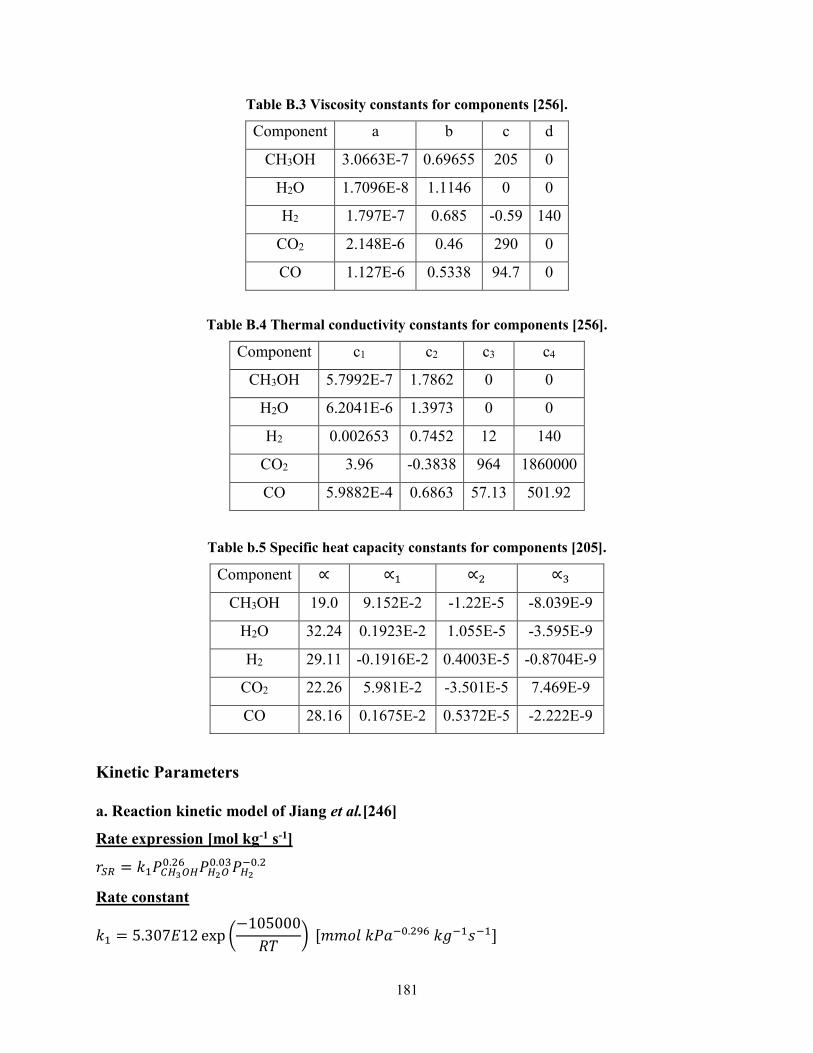
Appendix A Supporting Information of Chapter-3 173
Appendix B Supporting Information of Chapter 5 180
xiv
List of Figures
Figure 2-1 Reforming fuel selection criteria for fuel cell power generation systems (Refs
[2485960]) 15
Figure 2-2 Energy density of different fuels The values calculated by using the heating values and the
density values in Table 1 The density values under given conditions on the figure for hydrogen were
taken from Ref [63] and the density under given condition on the figure for methane was taken from
Ref [64] The energy densities at 0 oC and 1 bar for hydrogen and methane are 00127 MJL and
00397 MJL respectively 16
Figure 2-3 Change of the (a) methane conversion and hydrogen mol in the reformate gas for steam
reforming of (b) methane (c) ethanol (d) gasoline (e) diesel with variation of the SFuel ratio and the
reformation temperature 20
Figure 2-4 Change of the CO mol in the reformate gas for steam reforming of (a) methane (b)
ethanol (c) gasoline and (d) diesel with variation of the SFuel ratio and the reformation temperature
21
Figure 2-5 Methanol production and methanol usage in the market Refs [95-101] 25
Figure 2-6 O2Methanol ratio and H2 mol for autothermal reformation of methanol (a) The
reactants inlet temperature are equal to 350 oC (b) the reactants inlet temperature are equal to 25 oC
The reformation temperature is 350 oC for (a) and (b) The results are found for Case-2 (see Table 2-
5) 28
Figure 2-7 Variation of the methanol reformate gas composition as a function of temperature
CH3OH H2O=12 (1 mole methanol + 2 moles water) Calculations performed with the Aspen Plus
v88 [83] 32
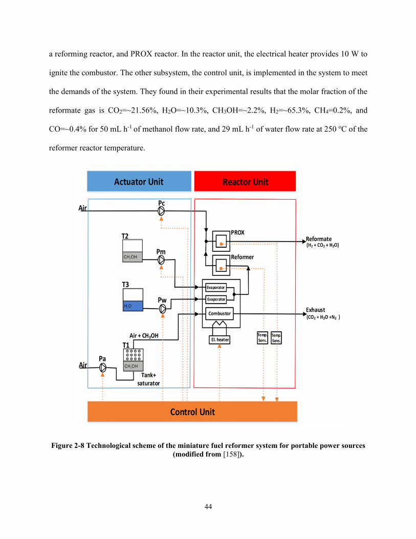
Figure 2-8 Technological scheme of the miniature fuel reformer system for portable power sources
(modified from [158]) 44
Figure 2-9 (a) Scheme (b) picture and (c) concept drawing of the commercial H3-350 RMFC
system Modified from Refs [179 188] 47
Figure 3-1 Schematic of the methanol reformer system 58
Figure 3-2 Effects of the steam carbon ratio and the reformer temperature on the H2 molar ratio in the
reformate gas 68
Figure 3-3 Effects of the steam carbon ratio and the reformer temperature on the CO molar ratio in
the reformate gas 68
xv
Figure 3-4 Effects of the reformer temperature and the current density on the fuel cell voltage The
results are obtained for (a) Tcell=160 [oC] (b) Tcell=170 [oC] (c) Tcell=180 [oC] and SC=15 cathode
stoichiometric ratio=2 70
Figure 3-5 Effects of the steam carbon ratio and the current density on the fuel cell voltage The
results are obtained for (a) Tcell=160 [oC] (b) Tcell=170 [oC] and Tref=240 [oC] cathode
stoichiometric ratio=2 71
Figure 3-6 Effects of the reformer temperature and the current density on the fuel cell voltage The
results are obtained for Tcell=160 [oC] SC=15 cathode stoichiometric ratio=3 71
Figure 3-7 Effects of the reformer temperature and the hydrogen utilization factor on the input fuel to
produce 350 W power from fuel cell (a) Tcell= 160 [oC] (b) Tcell= 170 [oC] (c) Tcell= 180 [oC] and
SC=15 cathode stoichiometric ratio=2 73
Figure 3-8 Effects of the reformer temperature and the hydrogen utilization factor on the input fuel
to produce 400 W power from fuel cell (a) Tcell= 160 [oC] (b) Tcell= 170 [oC] (c) Tcell= 180 [oC]
and SC=15 cathode stoichiometric ratio=2 74
Figure 3-9 Effects of the reformer temperature and the hydrogen utilization factor on the input fuel to
produce 450 W power from fuel cell (a) Tcell= 160 [oC] (b) Tcell= 170 [oC] (c) Tcell= 180 [oC] and
SC=15 cathode stoichiometric ratio=2 75
Figure 3-10 Effects of the reformer temperature and the hydrogen utilization factor on the heat
requirement of the reformer to produce 350 W power from fuel cell (a) Tcell= 160 [oC] cathode
stoichiometric ratio=2 (b) Tcell= 160 [oC] cathode stoichiometric ratio=5 and SC=15 76
Figure 3-11 Effects of the reformer temperature and the hydrogen utilization factor on the heat
requirement of the evaporator to produce 350 W power from fuel cell (a) Tcell= 160 [oC] cathode
stoichiometric ratio=2 (b) Tcell= 160 [oC] cathode stoichiometric ratio=5 and SC=15 78
Figure 3-12 Effects of the reformer temperature and the hydrogen utilization factor on the heat
production of the combustor to produce 350 W power from fuel cell (a) Tcell= 160 [oC] cathode
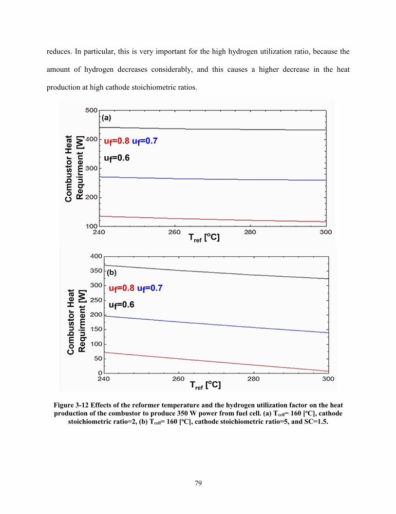
stoichiometric ratio=2 (b) Tcell= 160 [oC] cathode stoichiometric ratio=5 and SC=15 79
Figure 3-13 Fuel cell heat production for 350 W power generation Tcell=160 [oC] SC=15 cathode
stoichiometric ratio=2 80
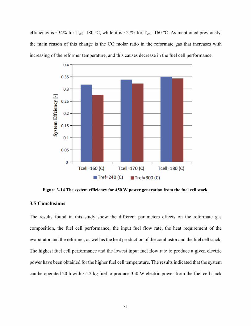
Figure 3-14 The system efficiency for 450 W power generation from the fuel cell stack 81
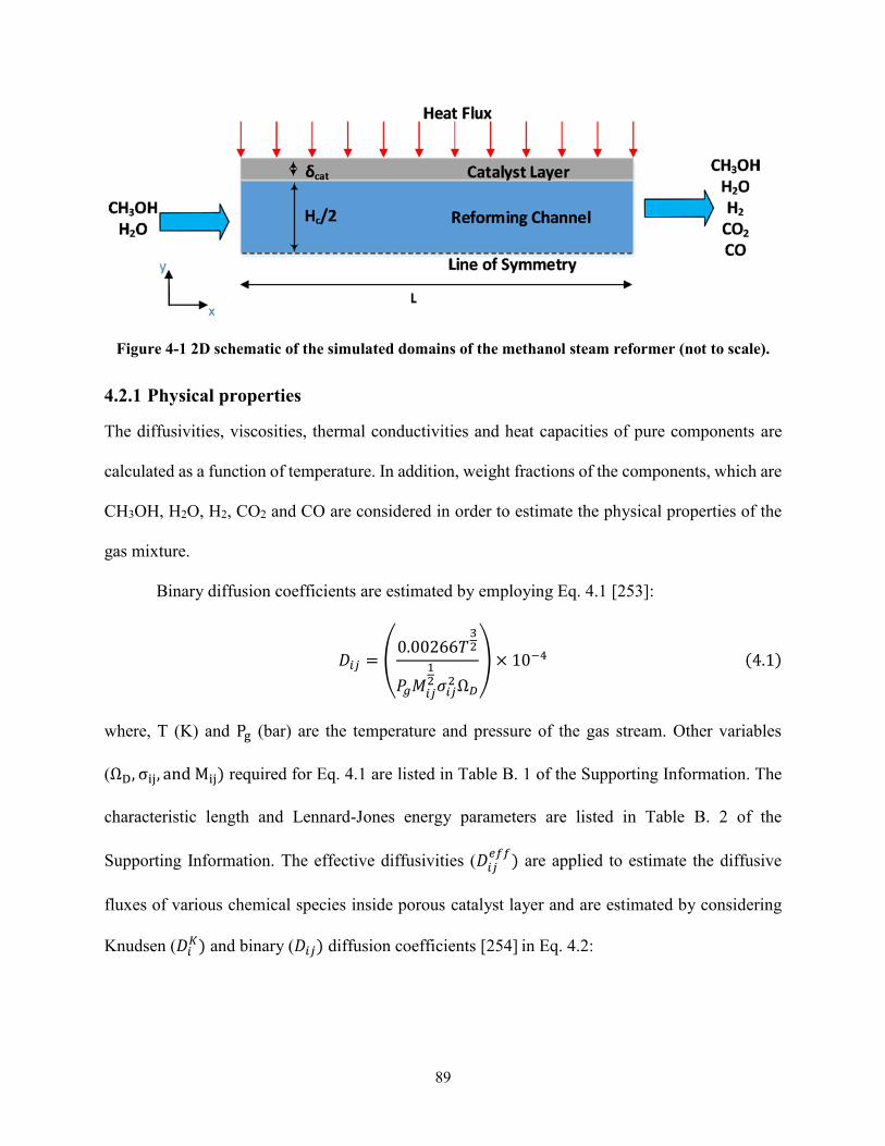
Figure 4-1 2D schematic of the simulated domains of the methanol steam reformer (not to scale) 89
Figure 4-2 Comparison of the methanol conversion between experimental values and model
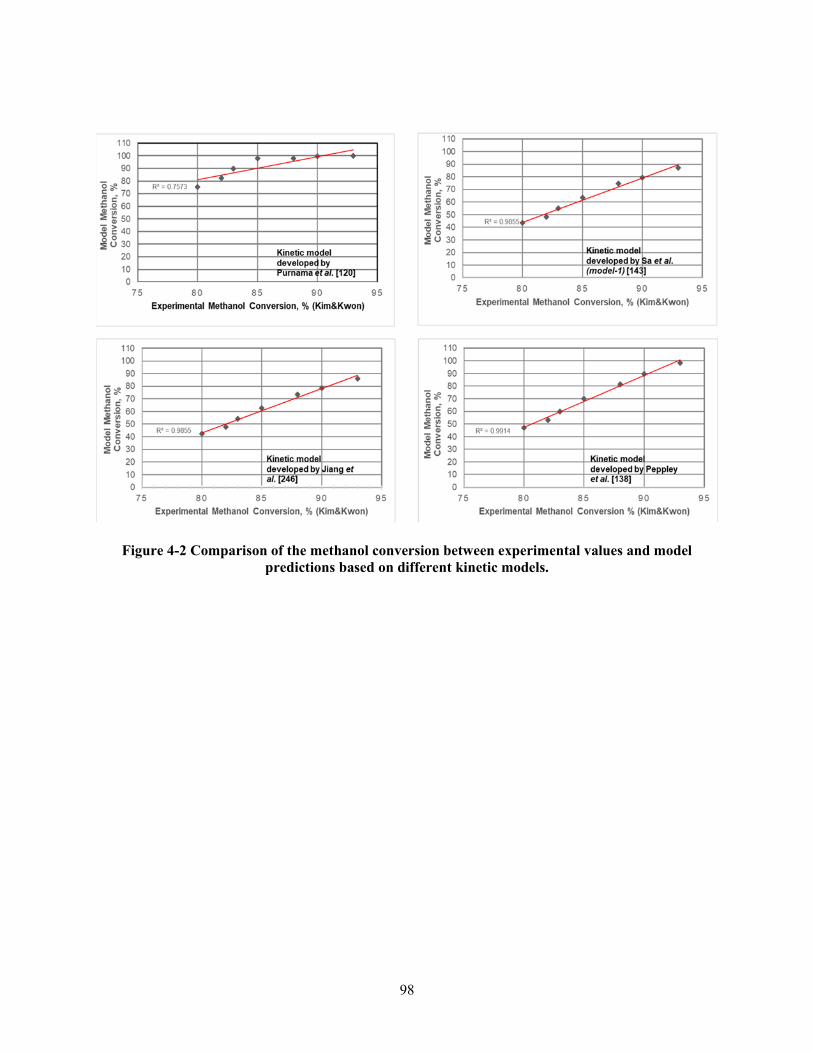
predictions based on different kinetic models 98
xvi
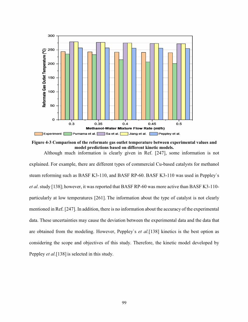
Figure 4-3 Comparison of the reformate gas outlet temperature between experimental values and
model predictions based on different kinetic models 99
Figure 4-4 Change of the methanol conversion with variation of the catalyst layer thickness at 252 oC
and 120601=04 inlet methanol flow rate to the channel (a) 00247 (molh) (b) 00494 (molh) 102
Figure 4-5 Change of the reaction rate of the steam reforming reaction with variation of the catalyst
layer thickness at 252 oC and 120601=04 inlet methanol flow rate to the channel (a) 00247 (molh) (b)
00494 (molh) 103
Figure 4-6 Change of the catalyst effectiveness for the steam reforming reaction and methanol
conversion with the variation of the porosity and catalyst layer thickness at 252 oC (a) 120601=04 (b)
120601=08 and (c) increase in methanol conversion () with the variation of the porosity from 04 to 08
105
Figure 4-7 Change of (a) the reformer temperature (b) the reaction rate of the steam reforming
reaction (c) the methanol conversion and (d) the hydrogen production with variation of the catalyst
layer thickness 120601 = 04 inlet methanol flow rate to the channel is equal to 00247 (molh)
Qsource = 1500Wm2 n = 0 107
Figure 4-8 Change of (a) the reformer temperature (b) the reaction rate of the steam reforming
reaction (c) the methanol conversion and (d) the hydrogen production with variation of the catalyst
layer thickness 120601 = 04 inlet methanol flow rate to the channel is equal to 00247 (molh)
Qsource = 32500Wm2 a = 100 n = 1 109
Figure 4-9 Change of the methanol conversion with variation of the catalyst layer thickness and
porosity Inlet methanol flow rate to the channel is equal to 00247 (molh) Qsource =
32500Wm2 a = 100 n = 1 111
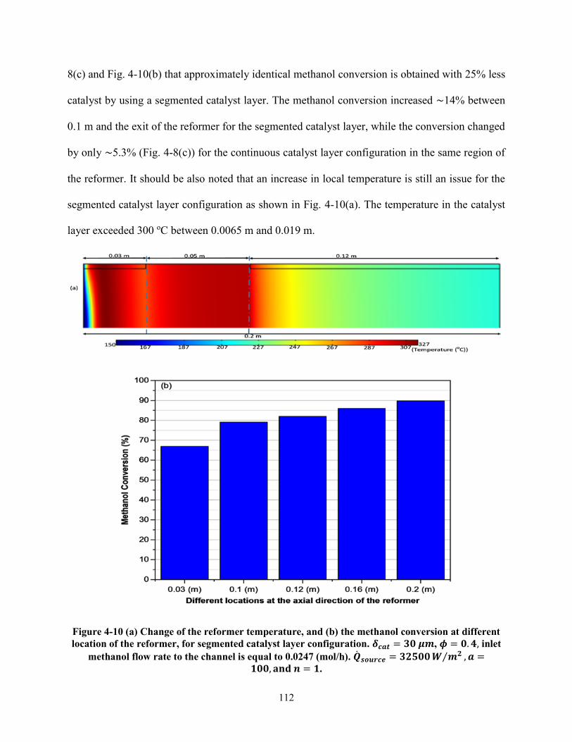
Figure 4-10 (a) Change of the reformer temperature and (b) the methanol conversion at different
location of the reformer for segmented catalyst layer configuration 120575119888119886119905 = 30 120583119898 120601 = 04 inlet
methanol flow rate to the channel is equal to 00247 (molh) 119876119904119900119906119903119888119890 = 325001198821198982 119886 =
100 and 119899 = 1 112
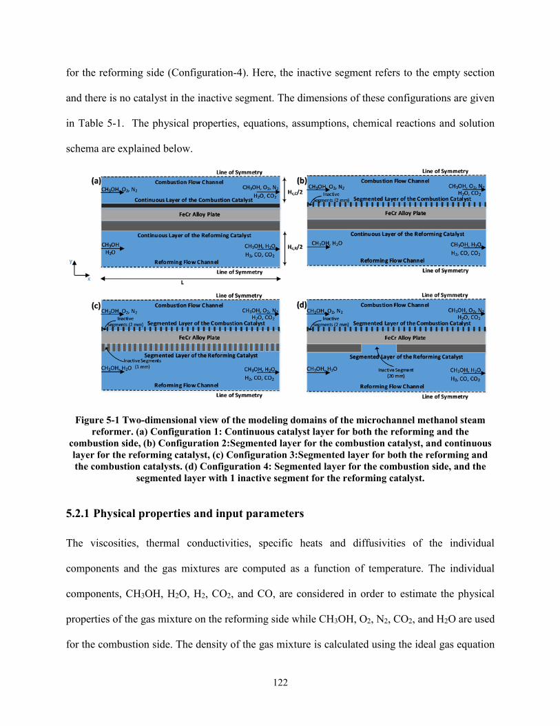
Figure 5-1 Two-dimensional view of the modeling domains of the microchannel methanol steam
reformer (a) Configuration 1 Continuous catalyst layer for both the reforming and the combustion
side (b) Configuration 2Segmented layer for the combustion catalyst and continuous layer for the
reforming catalyst (c) Configuration 3Segmented layer for both the reforming and the combustion
catalysts (d) Configuration 4 Segmented layer for the combustion side and the segmented layer with
1 inactive segment for the reforming catalyst 122
xvii
Figure 5-2 Comparison of the H2 production obtained by the model with (a) the results obtained from
the experiment [247] SC=11 the inlet temperature of the methanol-water mixture is equal to 150
oC The constant heat flux that is equal to 1000 Wm2 is used to provide heat for the endothermic
methanol steam reforming (b) the results obtained for the equilibrium condition SC=15 and the
reformer temperature is isothermal 131
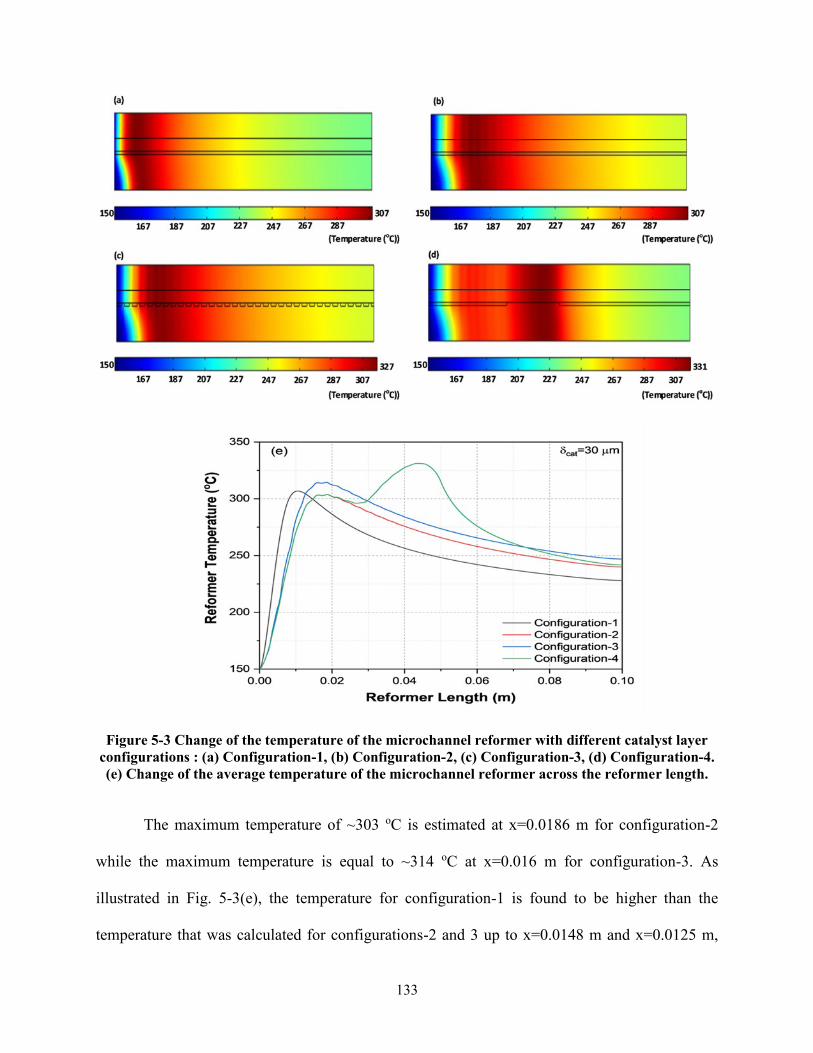
Figure 5-3 Change of the temperature of the microchannel reformer with different catalyst layer
configurations (a) Configuration-1 (b) Configuration-2 (c) Configuration-3 (d) Configuration-4
(e) Change of the average temperature of the microchannel reformer across the reformer length 133
Figure 5-4 Change of the heat flux for the combustion and the reforming side with the variation of the
catalyst layer configuration 135
Figure 5-5 (a) Change of the methanol conversion across the reformer length with variation of the
catalyst configurations (b) Total hydrogen production rate (molh) with variation of the catalyst layer
configuration 137
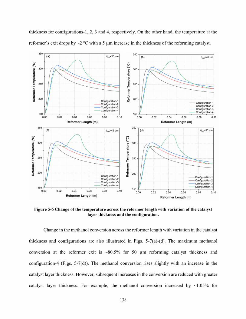
Figure 5-6 Change of the temperature across the reformer length with variation of the catalyst layer
thickness and the configuration 138
Figure 5-7 Change of the methanol conversion across the reformer length with variation of the
catalyst layer thickness and the configuration 139
xviii
List of Tables
Table 2-1 Advantages and disadvantages of reforming technologies (modified from [5253]) 12
Table 2-2 Comparison of alternative fuels (Data from [66162]) 17
Table 2-3 Impurity tolerances operating temperatures and main applications of commonly used fuel
cells (Refs [59 65-68]) 17
Table 2-4 Reformate gas-fueled commercial fuel cell systems 23
Table 2-5 Different cases in the estimation of thermodynamically feasible products for methanol
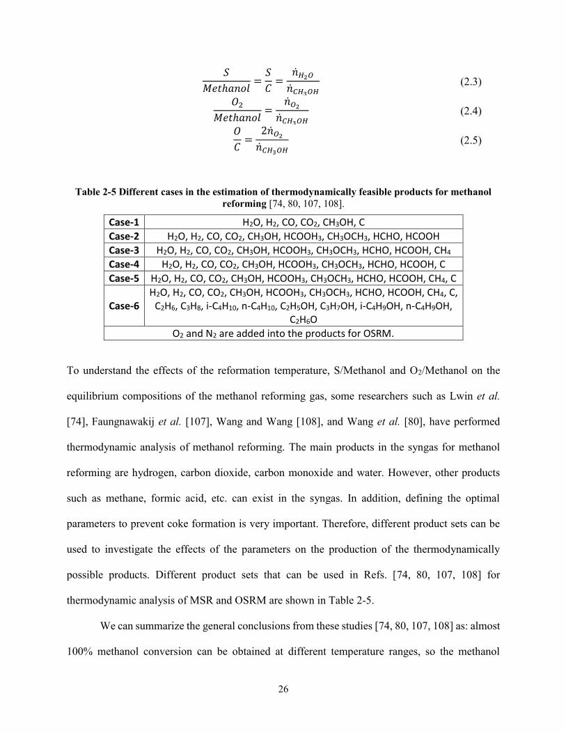
reforming [74 80 107 108] 26
Table 2-6 Specifications of different catalysts (adapted from Ref [121]) 31
Table 2-7 Reaction rate expressions for methanol reforming for different catalysts and reforming
processes 35
Table 2-8 Technical specifications of portable fuel cell prototype systems (adapted from Ref [169])
42
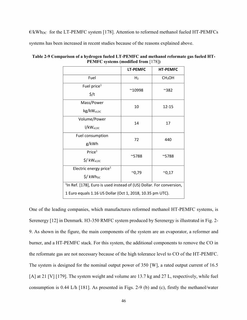
Table 2-9 Comparison of a hydrogen fueled LT-PEMFC and methanol reformate gas fueled HT-
PEMFC systems (modified from [178]) 46
Table 3-1 The input parameters of the system 60
Table 3-2 The input parameters to estimate the system efficiency of the system 61
Table 3-3 Validation of the model that is used for the methanol reformer simulation with
Experimental Studies 67
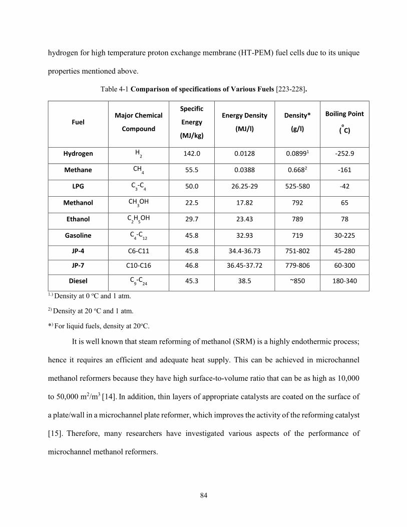
Table 4-1 Comparison of specifications of Various Fuels [223-228] 84
Table 4-2 The input parameters for the simulation of the microchannel reformer 93
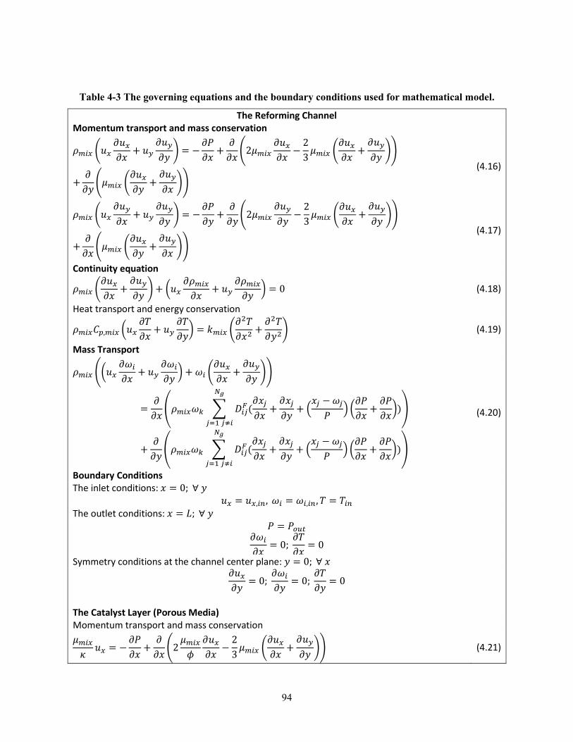
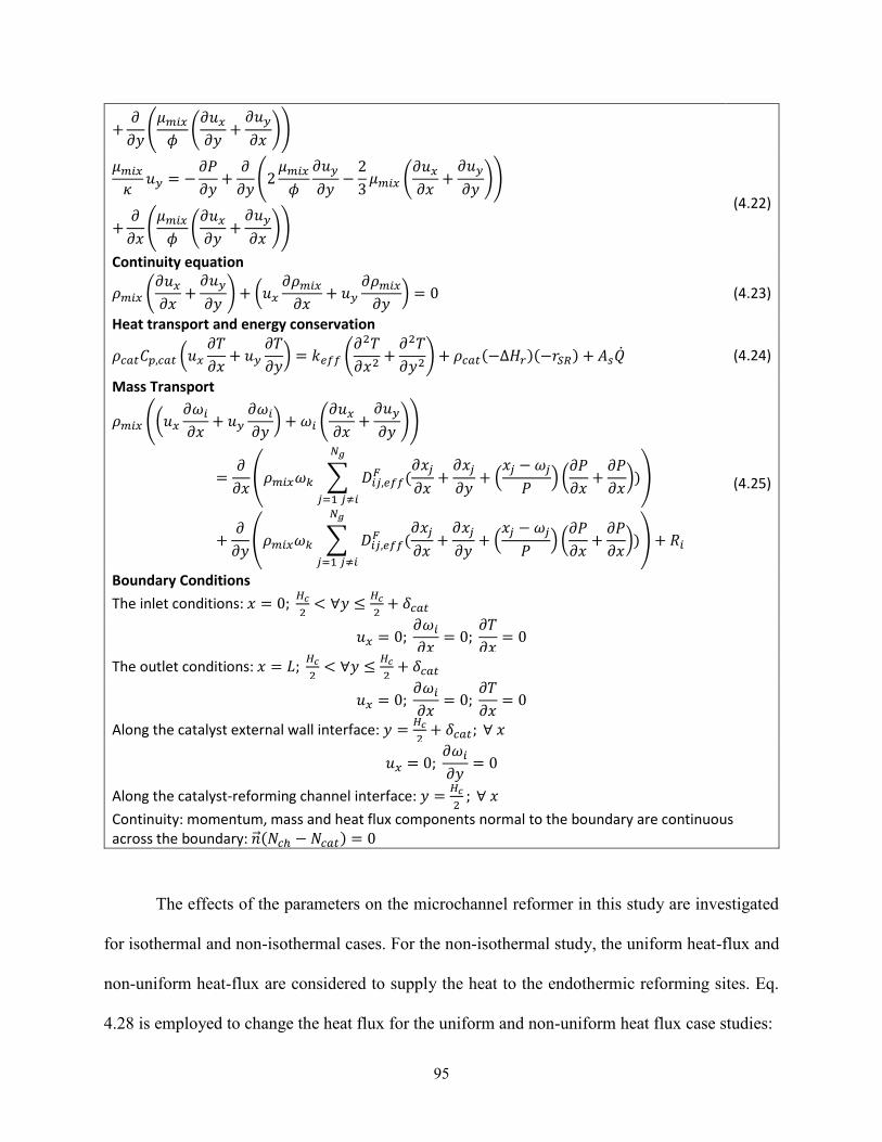
Table 4-3 The governing equations and the boundary conditions used for mathematical model 94
Table 4-4 Comparison of the model with 2D and 1D catalyst layer 113
Table 5-1 The input and geometric parameters of the computational domains for the modeling 124
Table 5-2 Methanol reformate-gas fueled HT-PEMFC power generation 141
xix
List of Symbols
As specific surface area (m2 m-3)
bxx and kxx pre-exponential factors for anode fuel cell model
Cp specific heat (J kg-1 K-1)
CSiT total surface concentration of site i (mol m-2)
D diffusion coefficient (m2 s-1)
dpa mean particle size (nm)
dpore mean pore size (nm)
Ei activation energy for rate constant of reaction i (kJ mol-1)
Esp the specific energy of the system (Wh kg-1)
F Faraday`s constant (C mol-1)
fi fugacity of the species i in the gas mixture (atm)
fio fugacity of species i at its standard state (atm)
G Gibbs free energy (J mol-1)
H height (m)
Hc channel height (m)
Hr reaction enthalpy (J mol-1)
hinhout enthalpy (J mol-1)
i cell current density (A cm-2)
io exchange current density (A cm-2)
xx
I electric current (A)
k thermal conductivity (W m-1 K-1)
ki rate constant for reaction i (units depend on the form of the expression)
kiinfin pre-exponential term in Arrhenius expression
Ki equilibrium constant of reaction i or adsorption coefficient for surface species
i
L reformer length (m)
LHVCH3OH lower heating value of methanol (J kg-1)
M molecular weight (g mol-1)
mCH3OH the mass of the stored fuel (kg)
mCH3OH mass flow rate of methanol (kg s-1)
mFC mass of the fuel cell (kg)
mH2O mass of the stored water (kg)
mRef mass of the complete reformer system (kg)
N number of components
Ncell number of cells
nCxHyOz molar ratio of fuel (mol s-1)
nH2O molar ratio of steam (mol s-1)
nO2 molar ratio of oxygen (mol s-1)
nxx molar flow rate (mol h-1)
P pressure (Pa)
xxi
PBOP balance of plant components power consumption (W)
Pel power generation of the fuel cell stack (W)
pi partial pressure of component i (bar)
Q heat transfer flux (W m-2)
R universal gas constant (J K-1 mol-1)
Ri component reaction rate (kg m-3 s-1)
ri rate of reaction (mol kg-1 s-1)
Rxx resistance (ohmcm2)
T temperature (K)
top the operation time (h)
u velocity (m s-1)
uf hydrogen utilization ratio (-)
Vcellop cell operation voltage (V)
Vo open circuit voltage (V)
x number of carbon atoms
y mol fraction
Greek Letters
δcat catalyst layer thickness (m)
ε characteristic Lennard-Jones energy (J)
η catalyst effectiveness factor (-)
120578119886 anode overpotential (V)
xxii
120578119904119910119904 system efficiency (-)
θ surface coverage (-)
κ porous media permeability (m2)
λ cathode stoichiometric ratio (-)
μ viscosity (kg s-1 m-1)
ρ density (kg m-3)
120588119888119886119905119888 density of the combustion catalyst layer (kg m-3)
120588119888119886119905119877 density of the reforming catalyst layer (kg m-3)
σ characteristic length (Å)
τ tortuosity (-)
ϕ porosity (-)
ω mass fraction (-)
ΩD diffusion collision integral
Subscript and superscripts
c combustion
cat catalyst
ch channel
eff effective
F Fickian
g gas phase
i j species indices
xxiii
K Knudsen
mix mixture
MD methanol decomposition
MS Maxwell-Stefan
SR steam reforming
R reforming
rWGS reverse water gas shift
WGS water gas shift
xxiv
List of Acronyms
APU auxiliary power unit
ATR auto-thermal reforming
BOP balance of plant
DMFC direct methanol fuel cell
EIA Energy Information Administration
FC fuel cell
FEM finite element method
HT high temperature
IEA International Energy Agency
IRMFC internal reformed methanol fuel cell
LT low temperature
MCFC molten carbonate fuel cell
OC oxygen to carbon ratio
OFuel oxygen to fuel ratio
OM oxygen to methanol ratio
OSRM oxidative steam reforming of methanol
PAFC phosphoric acid fuel cell
PEMFC polymer electrolyte membrane fuel cell
PROX preferential oxidation
RMFC reformed methanol fuel cell
xxv
SC steam to carbon ratio
SFuel steam to fuel ratio
SMR methanol steam reforming
SOFC solid oxide fuel cell
STP standard temperature and pressure
PEM polymer electrolyte membrane
POX partial oxidation
TEG triethylene glycol
Wth Watts thermal
1
Chapter 1
Introduction
11 Motivation and Objectives
Fuel cell (FC) technology is a promising technology for clean and efficient power generation
However this technology is not widely used today It is reported that the FC market size across
the world was valued at only USD 321 billion in 2016 [1] The most important reasons for this
are (1) the cost of this technology (2) challenges related to hydrogen transportation distribution
and storage
The cost of FCs must be reduced in order to stimulate more investment in research and
development (RampD) which would result in much needed improvements in this field At the same
time the demand for these fuel cells in the marketplace must increase and this would spur needed
investment In other words it is necessary to determine the most effective way to facilitate the
widespread use of FC technology Recent studies [2-4] have shown that FC systems have the
potential to become more common in the market for some niche applications such as backup power
generators forklifts aircraft auxiliary power unit (APU) applications power generation
applications in off-grid locations etc In addition Shaw et al [5] report that military personal
power generators consumer battery rechargers and specialized laptop computers are also
promising applications that require power in the range of 100 and 500 W
Customers are willing to accept the higher price of fuel cell technology as compared to
alternative technologies such as diesel generators and batteries for the niche markets mentioned
above because of the unique combination of characteristics of the FC systems These unique
characteristics can be listed as (1) quiet operation (2) low emissions (3) ability to operate in
2
extreme conditions (4) relatively low maintenance costs (5) quick refueling (6) low vibration
(7) high fuel efficiency (8) production of water and heat (9) extended run time (10) remote
monitoring capability [2-5] In particular the extended run time is the most important motivation
to prefer FC systems for these niche applications [2-4]
Other important barriers related to FC systems becoming more commonplace in the market
are the difficulties of hydrogen transportation distribution and storage Specifically hydrogen
storage is a serious issue for FC systems which desire extended run times Storage is difficult
because hydrogen exists at a very low density at standard temperature and pressure conditions
Therefore the occupied volume of the hydrogen gas under standard temperature and pressure
conditions is much higher than other fuels [6] Different storage methods such as compressed
hydrogen at very high pressures and cryogenic storage can be used to decrease the occupied
volume of the hydrogen However there are serious challenges related to the current hydrogen
storage methods for example the high pressure requirement for compressed storage of hydrogen
is an important issue Additionally the volume requirement is still very high even at elevated
pressures for the compressed storage It is reported [7] that the volume requirement is about 150 L
to store 6 kg of hydrogen at 700 bar The issue related to cryogenic storage of hydrogen is the
evaporation of hydrogen in the tank which is called the boil-off phenomenon [7] This causes
hydrogen losses between 03 and 5 per day depending on the current storage tank technology
[8] To overcome challenges related to hydrogen transportation distribution and storage methanol
can be used directly in direct methanol fuel cells (DMFCs) or it can be converted to hydrogen rich
syngas by employing various reforming methods to feed the FC systems serving as a practical and
promising alternative to hydrogen storage
3
Some of the important advantages of methanol are (1) It can be easily stored under many
environmental conditions because the boiling point of methanol is equal to 65 oC (2) The existing
fuel infrastructure with limited changes can be used for methanol distribution (3) It does not
include sulfur contents (4) Its reforming processes are easier than other fuels such as methane
diesel or ethanol because methanol reforming can be achieved at low temperatures with low steam
to carbon (SC) ratios [910]
Due to the advantages of methanol mentioned above it is currently used in the market as a
fuel for some specific niche applications of FC power generation systems [1112] The direct usage
of methanol without reforming is possible in DMFC systems however the DMFCs have cost
limitations due to their high platinum content Therefore the DMFC systems in the market are
generally used for small scale power generation applications of less than 100 W [211] The
methanol reformate gas fueled high temperature polymer electrolyte membrane fuel cells (HT-
PEMFCs) are preferred in the market for power generation higher than 100 W [12] The main
advantage of the HT-PEMFCs is that they can tolerate CO up to 3 because of their high operation
temperatures [13] Thus the methanol reformate gas can be directly feed to the HT-PEMFCs stack
without any additional equipment to remove CO [12]
Steam reforming of methanol (SRM) is commonly used for commercial methanol
reformate gas fueled HT-PEMFC systems [12] due to its higher efficiency than the other reforming
processes However efficient and adequate heat transfer is very important for SRM because it is a
highly endothermic process Efficient heat transfer can be provided by using microchannel plate
type heat exchanger reformers based on their high surface to volume ratio [14] There are also
other motivations to use microchannel plate heat exchanger reformers for the SRM process The
microchannel plate heat exchanger reformers improve the system dynamics catalytic activity and
4
mass transfer from the bulk flow to the catalyst surface [15-17] Due to these advantages higher
performance can be obtained from the methanol reformate gas fueled HT-PEMFC systems with
decreasing the system size
Although many studies have been conducted related to microchannel plate heat exchanger
methanol reformers there are still some questions which must be answered to aid in the efficient
design of a new generation of microchannel methanol reformers Therefore the focus of this study
is to develop a model for microchannel plate heat exchanger methanol reformers in order to answer
specific questions about the design of a new generation of microchannel methanol reformers for
HT-PEMFC systems
The main objectives of this thesis are as follows
bull Analyze a methanol reformate gas fueled HT-PEMFC system for power generation
in the range of 100 to 500 W to investigate the effects of the main operation
parameters on the system
bull Investigate the effects of temperature distribution on the performance of a
microchannel methanol reformer
bull Develop a two dimensional (2D) steady state model to understand the effects of
catalyst layer thickness on a microchannel plate heat exchanger methanol reformer
while considering different catalyst layer structural characteristics
bull Demonstrate the feasibility of various catalyst layer configurations to improve the
performance of a microchannel plate heat exchanger methanol reformer and to
decrease the amount of the catalyst needed
5
12 Thesis Structure
There are six chapters including the introduction and conclusion in this thesis Chapter 2 has been
submitted to a peer reviewed journal and Chapter 3 to 5 have been published in peer reviewed
journals Each chapter is briefly summarized below
Chapter 2 presents a critical review of the methanol reforming process The main novelty
of this chapter is its coverage of important aspects of methanol reforming processes for fuel cell
power generation applications In this chapter the focus is on practical points related to methanol
reforming The chapter summarizes the recent studies related to this subject and explains
promising applications of the methanol reformate gas fueled fuel cell systems In the first section
of this chapter the studies covering the reforming of different fuels are presented and the
characteristics of commercial reformate gas fueled systems are compared Fuel reforming
processes are also reviewed in this section In the next section advancements in methanol
reforming technology are explained The methanol reforming catalysts and reaction kinetics
studies by various researchers are reviewed and the advantages and disadvantages of each catalyst
are discussed then the studies about different types of reformers are presented In the last section
of Chapter 2 methanol reformate gas fueled fuel cell systems are reviewed Chapter 2 has been
submitted to the International Journal of Energy Research
Chapter 3 investigates the effects of different operational parameters on methanol
reformate gas fueled HT-PEMFC systems for portable power generation applications The system
is simulated using Aspen Plus with Fortran calculator to conduct detailed parametric studies and
estimate the systemrsquos efficiency The contents of this chapter have been published in the journal
of Energy Conversion and Management after peer review [18] The results obtained in Chapter 3
are used to select inlet conditions for modeling the microchannel methanol reformer in Chapters 4
and 5
6
Chapter 4 presents a steady state 2D multiphysics model of a microchannel methanol
steam reformer to investigate the effects of catalyst layer thickness on the performance of a
microchannel methanol steam reformer The effects of temperature distribution on the reformer
are also studied for isothermal and nonisothermal situations In addition the feasibility of the
segmented catalyst layer to decrease the amount of the catalyst is demonstrated The main novelty
of this chapter is its consideration of a 2D domain for the thin coating of the reforming catalyst to
account for the internal diffusion limitations and coating catalyst`s properties This chapter has
been published in the journal of Energy and Fuels [6]
Chapter 5 presents various catalyst layer configurations for the microchannel plate heat
exchanger methanol steam reformer The model that is developed in Chapter 4 is expanded in this
chapter The heat for the endothermic methanol steam reforming reactions is provided by coupling
catalytic methanol combustion reactions on the opposite side A methodology is also presented in
the chapter to solve convergence issues in the numerical analysis In addition the effects of catalyst
layer thickness on the performance and the temperature distribution of the reformer with variation
of the catalyst layer configurations are investigated Furthermore the power generation of a HT-
PEMFC stack is estimated for the optimal catalyst layer configurations This chapter has been
published by the journal of Energy Conversion and Management [19] after peer review
Chapter 6 highlights the important results obtained in this thesis and gives
recommendations for the future directions of this work
7
Chapter 2
An Overview of the Methanol Reforming Process Comparison of
Fuels Catalysts Reformers and Systems
The following chapter is a ldquopre-printrdquo of an article accepted for publication in International
Journal of Energy Research
Herdem MS Younessi-Sinaki M Farhad S Hamdullahpur F An overview of the methanol
reforming process comparison of fuels catalysts reformers and systems Int J Energy Res
2019 accepted
The final official version of the article can be downloaded from the journal`s website via this
DOI link when it becomes available
DOI 101002er4440
21 Introduction
Many organizations such as the World Energy Council [20] EIA [21] and IEA [22] predict that
world energy requirements will dramatically increase in the near future However today this
increasing energy requirement issue is not sufficient to explain all of the studies in the energy field
To comprehend deeply we should also consider the environment energy security affordable
energy production end use of energy including stationary power generation applications portable
power generation applications etc In addition one of these issues is sometimes more important
than the others For example nowadays energy security is a critical issue for the oil and gas
importing countries because of the destabilization of these countries [2324] Of course there is
no magic to solve all of the issues related to energy However various unique solutions can be
applied for each issue Two possible solutions are diversification of energy supplies and choosing
the appropriate technology for different applications
8
Hydrogen is a very promising energy carrier to diversify our energy supply because it can
be produced using a wide variety of sources and it can be used for various purposes such as
ammonia production [25] energy storage [26-29] methanol synthesis diesel and natural gas
production [30]
Hydrogen as a fuel also has promising potential to produce power that is environmentally
friendly and has high efficiency by employing fuel cells One of the most important barriers to fuel
cell systems becoming more commonplace for power generation applications - in particular for
portable applications - involves the difficulties regarding hydrogen storage Hydrogen has higher
gravimetric energy density than hydrocarbon and alcohol fuels (see Fig 1) but in terms of its
volumetric energy density (Whl) it is significantly less dense than other fuels [31] The reason is
that the occupied volume of 1 kg of hydrogen as a gas under standard temperature and pressure
conditions is much higher than that of hydrocarbon and alcohol fuels For example 1 kg of
hydrogen has nearly six times as much energy (142 MJ) as compared to a kg of methanol (225
MJ) However the occupied volume of 1 kg of methanol at 25oC and 1 atm is about 126 L while
this value is ~12300 L for 1 kg of hydrogen To decrease the occupied volume of hydrogen
efficient methods of storage are required These methods are (1) Compressed gas at standard
temperature and very high pressure (2) Cryogenic liquid at standard pressure and 20 K (3)
Chemical storage by using Magnesium Hydride Calcium Hydride Sodium Hydride etc (4)
Physical storage (metal organic framework) [832] Despite the number of choices available there
are also many important issues related to these methods which need to be considered such as the
requirement of high pressure for compressed storage of hydrogen or expensive materials and very
low temperatures for liquefaction of hydrogen [8] To overcome these problems alternative fuels
9
such as natural gas ethanol methanol dimethyl ether (DME) gasoline and diesel can be converted
to hydrogen rich gas using fuel reforming in order to provide the required fuel for fuel cells
The other important motivation for the reforming of natural gas ethanol methanol DME
gasoline and diesel is that these fuels can be produced from biomass in an environmentally friendly
way Although there are some ethical and social issues related to the first generation biofuels
derived from food feedstocks the second-generation biofuels will be derived from non-edible
feedstocks such as wood agricultural residues forestry waste and municipal wastes [33-36] There
are currently demonstration pilot and commercial second-generation biofuel plants in operation
[35] In addition the third and fourth generation biofuels will be derived from algae This process
is currently in the research and development stage and presents a very attractive option for the
production of biofuels [35]
Due to the aforementioned advantages of reforming alternative fuels fuel reforming has
received attention from a variety of research groups throughout the world Many review studies
have been undertaken to examine various aspects of fuel reforming One of the early review papers
was published by Haryanto et al [37] in 2005 to examine and compare different catalysts (oxide
catalysts metal-mixture-based catalysts and noble-metal-based catalysts) for steam reforming of
ethanol (ESR) Contreras et al [38] recently reviewed noble metals and non-noble metals as
catalysts for ESR They provided information about the major catalytic studies of ESR up to 2013
A review of solar thermal catalytic reforming of natural gas was conducted by Simakov et al [39]
In this study they presented equilibrium constraints of methane steam and dry reforming and also
critically evaluated recent studies related to various aspects of solar thermal reforming of methane
catalysis Sheu et al [40] discussed recent developments and potential innovations such as
chemical looping and membrane reactors in relation to solar methane reforming systems Studies
10
of reforming processes for different types of fuels and the related hydrogen purification and CO
reduction processes were reported by Qi et al [41] Hansen [42] focused on fuel processing
systems with an emphasis on the industrial aspects of fuel cells and electrolyzers LeValley et al
[43] introduced recent developments in steam reforming hydrogen production technologies and
water gas shift catalysts Recent and past research activities (such as catalyst development reactor
design and testing for reforming) and market applications for microreactors were explained in Ref
[1544] Iulionelli et al [45] also provided an overview of studies on conventional and membrane
reactors for methanol steam reforming In addition to the mentioned studies Sa et al [46]
illustrated the latest developments in copper-based and group 8-10 metal-based catalysts for
methanol steam reforming and Yong et al [47] discussed methanol reforming Cu-based catalyst
surface reaction mechanisms and reaction schemes Palo et al [48] in 2007 reviewed studies
related to methanol steam reforming for hydrogen production to provide information about the
methanol reforming systems system challenges and catalysts Sengodan et al [49] recently (2018)
discussed partial oxidation of methane ethanol and methanol They focused on recent
improvements in catalysts for the partial oxidation of methane and alcohols In addition Zang et
al [10] recently reviewed the latest progress and achievements in integrated methanol steam
reformer high temperature polymer electrolyte membrane fuel cell (HT-PEMFC) power
generation systems
As shown from the review papers mentioned above there is no review paper in the
literature that covers all of the aspects of methanol reforming This review paper will mainly focus
on current studies from 2010 to 2018 involving methanol reforming Firstly we will compare fuel
reforming processes for different fuels by summarizing the works covering the reforming of
different types of fuels using a thermodynamic framework Secondly we will discuss recent and
11
past research activities regarding methanol reforming Then different types of reformers and the
effects of different parameters on methanol reforming will be explained Information will then be
provided on studies involving the integration of methanol reforming into reformate gas-fueled fuel
cell systems In this study the main goal is to provide a clear definition of the key parameters and
technologies used in methanol reforming for fuel cell applications
211 An Overview of the Fuel Reforming Process
Fuel reforming is a conversion process whereby fuels are converted to hydrogen rich gas Different
types of fuels consisting of light hydrocarbons such as methane and ethane liquid hydrocarbons
such as diesel and jet fuels and alcohols such as methanol and ethanol can be used for fuel
reforming processes [5051]
Steam reforming partial oxidation and oxidative steam reforming (or autothermal
reforming) are three different processes to convert hydrocarbon and alcohol fuels to hydrogen rich
gas Advantages and disadvantages of these processes are shown in Table 2-1 Fuel and steam
react in steam reforming via an endothermic reaction The main advantages of steam reforming
are the highest hydrogen yield can be obtained and reforming temperature is lower than partial
oxidation and oxidative steam reforming [52 53] However start-up time and dynamic response
are two important issues related to this reforming process [53] Conversion of fuels to hydrogen
rich gas with oxygen is called partial oxidation and is an exothermic reaction Partial oxidation can
be employed for quick start-up and dynamic response [5253] Although partial oxidation has quick
start-up and better dynamic response the lower hydrogen yield and relatively high processing
temperature are important challenges with regards to this reforming process To achieve the
advantages of both steam and partial oxidation reforming steam and a certain amount of air can
12
be used together This process is called oxidative steam reforming Oxidative steam reforming can
be endothermic exothermic or thermally neutral when the heat of reaction is equal to zero For
the thermally neutral situation the oxidative steam reforming is called autothermal reforming
Table 2-1 Advantages and disadvantages of reforming technologies (modified from [5253])
Type Advantages Disadvantages
Steam Reforming bull Highest H2 yield
bull Oxygen not required
bull Most extensive industrial
experience
bull Lowest process temperature
bull Best H2CO ratio for H2
production
bull Requires careful thermal
management to provide heat
for reaction especially for (a)
start-up and (b) dynamic
response
bull Only works on certain fuels
Partial Oxidation bull Quick to start and respond
because reaction is exothermic
bull Quick dynamic response
bull Less careful thermal management
required
bull Works on many fuels
bull Low methane slip
bull Lowest H2 yield
bull Highest pollutant emissions
(HCs CO)
bull Low H2CO ratio
bull Very high processing
temperatures
Autothermal reforming bull Simplification of thermal
management by combining
exothermic and endothermic
reactions in same process
bull Compact due to reduction in heat
exchangers
bull Quick to start
bull Lower process temperature than
partial oxidation
bull Low methane slip
bull Low H2 yield
bull Limited commercial
experience
bull Requires careful control
system design to balance
exothermic and endothermic
processes during load changes
and start-up
Global reactions for steam reforming partial oxidation and oxidative steam reforming can
be written as follows for hydrocarbons and alcohols (methanol and ethanol) [44 51-53]
13
Steam reforming of hydrocarbons
119862119909119867119910 + 1199091198672119874 harr 119909119862119874 + (1
2119910 + 119909)1198672
(R21)
∆119867119900 = ℎ119910119889119903119900119888119886119903119887119900119899 119889119890119901119890119899119889119890119899119905 119890119899119889119900119905ℎ119890119903119898119894119888
Steam reforming of methanol and ethanol
1198621198673119874119867 + 1198672119874 harr 1198621198742 + 31198672 ∆119867119900 = +49 119896119869119898119900119897 (R22)
11986211986731198621198672119874119867 + 31198672119874 harr 61198672 + 21198621198742 ∆119867119900 = +1733 119896119869119898119900119897 (R23)
Partial oxidation of hydrocarbons
119862119909119867119910 +119909
2(1198742 + 3761198732) harr 119909119862119874 +
119910
21198672 + (
119909
2)3761198732
(R24)
∆119867119900 = ℎ119910119889119903119900119888119886119903119887119900119899 119889119890119901119890119899119889119890119899119905 119890119909119900119905ℎ119890119903119898119894119888
Partial oxidation of methanol and ethanol
1198621198673119874119867 +1
2(1198742 + 3761198732) harr 1198621198742 + 21198672 + (
1
2) 3761198732 ∆119867
119900 = minus1932 119896119869119898119900119897 (R25)
11986211986731198621198672119874119867 +3
2(1198742 + 3761198732) harr 31198672 + 21198621198742 + (
3
2) 3761198732 ∆119867
119900
= minus552 119896119869119898119900119897 (R26)
Oxidative steam reforming of hydrocarbons
119862119909119867119910 + 119899(1198742 + 3761198732) + (119909 minus 2119899)1198672119874 harr 119909119862119874 + (119909 minus 2119899 +119910
2)1198672 + (119899)3761198732
(R27) ∆119867119900 = ℎ119910119889119903119900119888119886119903119887119900119899 119889119890119901119890119899119889119890119899119905 119886119899119889119900119909119910119892119890119899119891119906119890119897119903119886119905119894119900 119889119890119901119890119899119889119890119899119905 (It can be
endothermic exothermic or thermally neutral)
Oxidative steam reforming of methanol and ethanol
119862119909119867119910119874119911 + 119899(1198742 + 3761198732) + (119909 minus 2119899 minus 119911)1198672119874
harr 119909119862119874 + (119909 minus 2119899 minus 119911 +119910
2)1198672 + 119899(376)1198732 (R28)
∆119867119900 = 119888ℎ119886119899119892119890119886119887119897119890 119889119890119901119890119899119889119904 119900119899119900119909119910119892119890119899119891119906119890119897 ratio
Coke formation reactions should also be considered for the reforming process because coke
formation can rapidly deactivate the catalyst and block the reactor [54] Dominant reactions that
are responsible for coke formation are given as follows [54-58]
14
Coke formation by Boudouard reaction
2119862119874(119892) harr 1198621198742(119892) + 119862(119904) ∆119867119900 = minus1724 119896119869119898119900119897 (R29)
Coke formation by CH4 decomposition
1198621198674 harr 21198672 + 119862(119904) ∆119867119900 = +749 119896119869119898119900119897 (R210)
Carbon monoxide reduction reaction
119862119874(119892) + 1198672(119892) harr 1198672119874(119892) + 119862(119904) ∆119867119900 = minus1304 119896119869119898119900119897 (R211)
Carbon dioxide reduction reaction
1198621198742 + 21198672 harr 119862 + 21198672119874 ∆119867119900 = minus901 119896119869119898119900119897 (R212)
22 Fuel Selection for Fuel Cell Applications and Reforming of Various Fuels
Different fuels can be used to feed fuel cells for power generation However the main question is
how we can choose a suitable fuel for fuel cell power generation systems To select a fuel we
should consider the application area of the system As shown in Fig 2-1 the fuel cell systems can
be used for different applications Possible applications of fuel cell power generation systems need
different desired system properties that are listed in Fig 2-1 For example on-site availability of
the fuel and high efficiency to produce power and heat are important for stationary power
applications while start-up time weight and volume of the system long-run time are desired
system properties for portable power generation applications
15
Figure 2-1 Reforming fuel selection criteria for fuel cell power generation systems (Refs
[2485960])
To decide which fuel can be used for a particular application different fuel properties such
as density boiling point energy density etc should be considered The properties and energy
densities of various fuels are shown in Table 2-2 and Fig 2-2 respectively As seen in Table 2-2
the hydrogen density at gas phase is very low compared to the other fuels The hydrogen density
at 0 oC and 1 bar is only 009 kg m-3 Therefore its energy density is only equal to 00127 MJL at
0 oC and 1 bar As illustrated in Fig 2-2 the energy density of the hydrogen significantly increases
at high pressures and 25 oC and in the liquid phase at very low temperatures However its energy
16
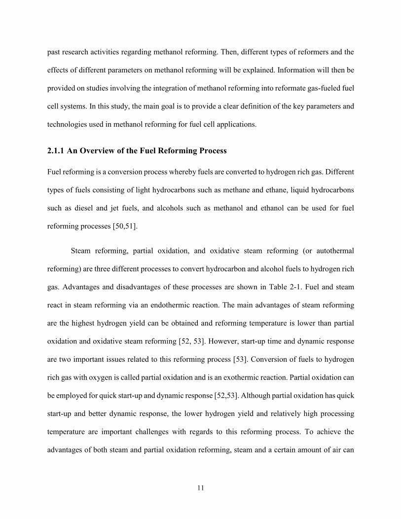
density is still relatively lower than the other fuels Due to the challenges related to hydrogen
storage hydrogen is not particularly suitable for the systems that need to run for long durations
Not only hydrogen storage but also hydrogen availability is a serious issue regarding usage of pure
hydrogen for fuel cell power generation applications To overcome these problems reforming of
alternative fuels can be used for the production of hydrogen rich syngas to feed a fuel cell
Figure 2-2 Energy density of different fuels The values calculated by using the heating values and
the density values in Table 1 The density values under given conditions on the figure for hydrogen
were taken from Ref [63] and the density under given condition on the figure for methane was
taken from Ref [64] The energy densities at 0 oC and 1 bar for hydrogen and methane are 00127
MJL and 00397 MJL respectively
17
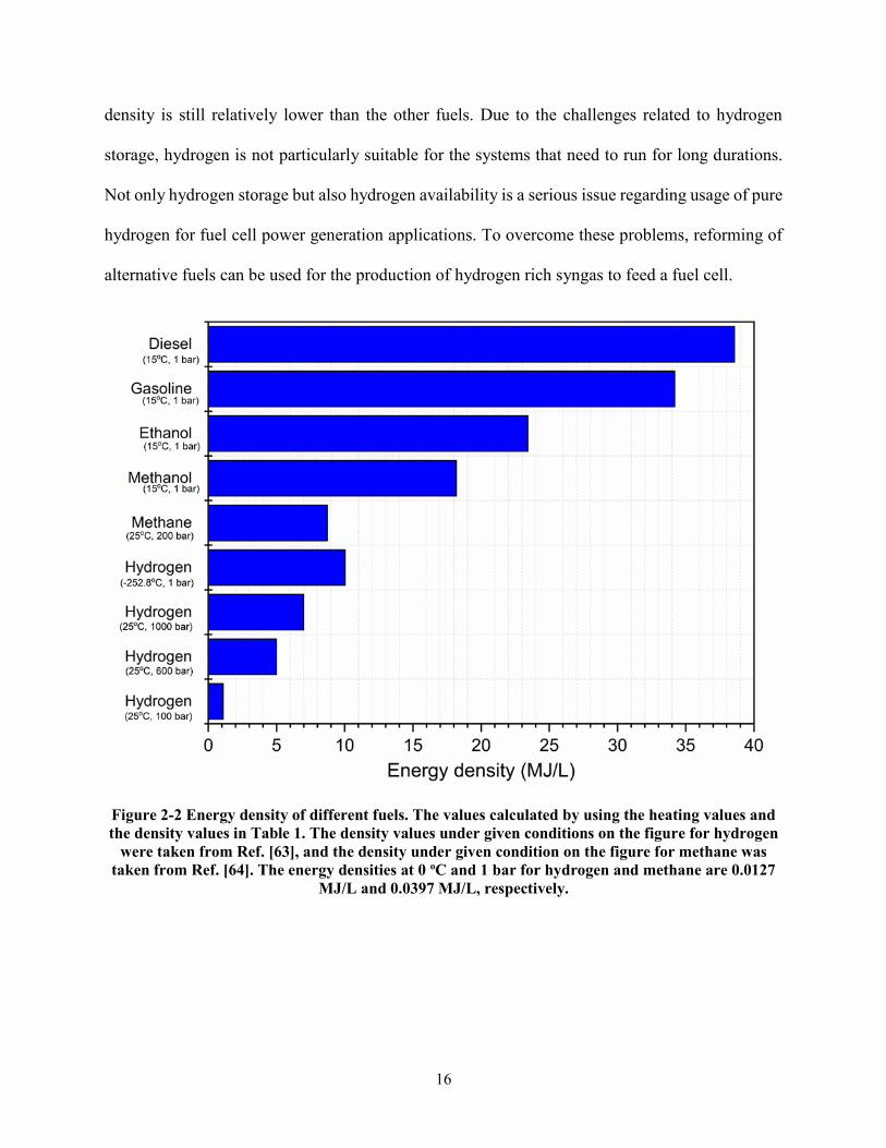
Table 2-2 Comparison of alternative fuels (Data from [66162])
Hydrogen Methane Dimethyl
ether Methanol Ethanol Gasoline1 Diesel1
Formula H2 CH4 CH3OCH3 CH3OH C2H5OH C7H16 C14H30
Density [kgm3]
0092 07162 665 7913 7893 7373 8463
C content wt
0 75 522 375 521 86 86
H2 content wt
100 25 13 125 13 14 14
LHV [MJkg]
120 50 2862 199 267 434 426
HHV [MJkg]
1417 555 43 23 297 464 456
Boiling point [oC]
-2529 -161 -249 65 78 30-225 180-340
Sulfur Content (ppm4)
0 ~7-25 0 0 0 ~200 ~250
1The properties of these fuels depend on the composition Average values are given on the table 2 Density at P=1 bar and T=0 oC 3 Density at P=1 bar and T=15 oC 4 Mass basis
Table 2-3 Impurity tolerances operating temperatures and main applications of commonly used
fuel cells (Refs [59 65-68])
Impurity
Tolerance
Levels
LT-PEMFC HT-
PEMFC PAFC MCFS SOFC
CO Poison (lt10 ppm)
Poison
(lt3 at
180 oC)
Poison (lt2
at 200oC) Fuel Fuel
CO2 Diluent Diluent Diluent Re-circulated Diluent
Sulfur
compounds Poison (lt1 ppm)
Poison
(lt20 ppm)
Poison (lt100
ppm)
Poison (lt1
ppm)
Poison (lt1
ppm)
Other
contaminants
Other contaminants should be considered such as halides trace metals and
nitrogen compounds
Operating
Temperatures
(oC)
60-80 110-1801 160-220 600-700 800-1000
Main
Application
Area
Portable
Applications
(military and
consumer
electronics)
APUs
APUs
Military
portable
power
needs
Stationary
applications
APUs
Stationary
applications
APUs
Stationary
applications
APUs
18
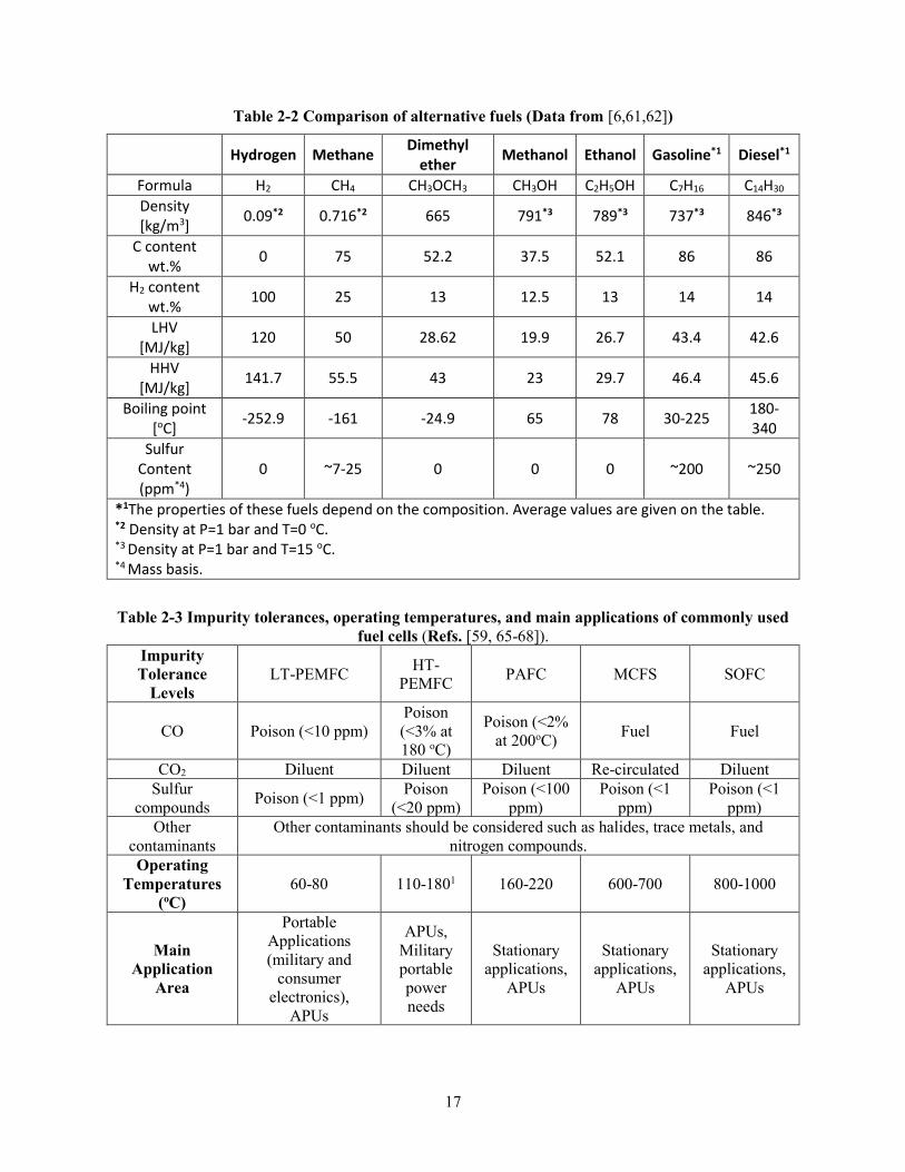
One of the most important points that should be considered in choosing a reforming fuel
for fuel cell power generation systems is the properties of fuel cell types To obtain the desired
system properties different fuel cell types are integrated into the system For example solid oxide
fuel cells (SOFC) are suitable when high efficiency for power and heat generation is desired while
low temperature polymer electrolyte membrane fuel cells (LT-PEMFC) are used when the start-
up time is critical for the power generation applications [59] To select the best suitable reforming
fuel for different fuel cell types impurity tolerance levels of the fuel cells and the operation
temperature of the fuel cells should be considered In Table 2-3 impurity tolerance levels and
operation temperatures for different types of fuel cells are shown As shown in the table all fuel
cell types are sensitive to sulfur compounds Therefore sulfur levels must be decreased if the fuel
includes sulfur compounds (see Table 2-2) As seen also in Table 2-3 the CO level in the reformate
gas must be less than a certain level for some types of fuel cells to prevent poisoning of the fuel
cell catalyst In addition close or identical reformation temperature and the operation temperature
of the fuel cells are significant advantages used to decrease the system complexity
Thermodynamic analysis is a practical tool to reveal optimum reformation temperature of
various fuels and the effects of different operating parameters on the reformate gas composition
Therefore thermodynamic analysis is commonly used in the literature in order to estimate the
effects of reforming temperature pressure water-to-feed ratio and oxygen-to-feed ratio on the
equilibrium compositions of reforming processes as well as to compare the feasibility of
reforming various fuels and to obtain fundamental information such as coke formation boundaries
and equilibrium conversion regarding different reforming processes Garcia and Laborde [69]
published in 1991 one of the early papers about thermodynamic analysis of the steam reforming
of ethanol Since then there have been many papers related to thermodynamic analysis of
19
reforming different types of fuels These papers are included in but not limited to studies
accomplished by Lutz et al [70 71] in 2003 and 2004 Ahmed and Krumpelt [72] in 2001 Fishtik
et al [73] in 2000 Lwin et al [74] in 2000 Kang and Bae [75] in 2006 Liu et al [76] in 2008
Shi and Bayless [77] in 2008 Authayanun et al [78] in 2010 Li et al [79] in 2011 Wang et al
[80] in 2012 and Cui and Kaeligr in 2018 [81] In these studies Gibbs free energy minimization
method has been commonly used to estimate equilibrium compositions of the reaction systems
without requiring specific reactions reaction kinetics or catalyst information For the Gibbs free
energy minimization method only possible components in the product must be defined The Gibbs
free energy minimization can be formulated as [31]
119898119894119899119899119894sum119899119894
119873
119894=1
(119866119894119900(119879) + 119877119879119897119899 (
119875
119875119903119890119891) + 119877119879119897119899 (
119899119894sum 119899119895119873119895=1
)) (21)
Specified chemical reactions with equilibrium constants [39 82] can be used as a second method
to estimate the equilibrium composition
Effects of the reformation temperature and steam to fuel (SFuel) ratio (see Eq22)
conditions on steam reforming of methane ethanol gasoline and diesel (methanol reforming is
mentioned in detail in the next section) were investigated in this review paper The results were
published in the literature reproduced and organized to compare steam reforming of different
process to give an overview to the readers
20
Figure 2-3 Change of the (a) methane conversion and hydrogen mol in the reformate gas for
steam reforming of (b) methane (c) ethanol (d) gasoline (e) diesel with variation of the SFuel ratio
and the reformation temperature
21
Figure 2-4 Change of the CO mol in the reformate gas for steam reforming of (a) methane (b)
ethanol (c) gasoline and (d) diesel with variation of the SFuel ratio and the reformation
temperature
Gibbs free energy minimization method was used to estimate the equilibrium
compositions RGibbs reactor [82] in Aspen Plus [83] was employed for the minimization of Gibbs
energy of the system Fig 2-3 shows the effects of the temperature and SFuel ratio on the methane
conversion (Fig 2-3(a)) and the hydrogen mol (wet basis) in the reformate gas for methane
(Fig 2-3(b)) ethanol (Fig 2-3(c)) gasoline (Fig 2-3(d)) and diesel (Fig 2-3(e)) Effects of the
22
temperature and SFuel ratio on the CO mol (wet basis) are also illustrated in Fig 2-4(a)-(d)
SFuel ratio is defined as consumption of steam per mole of the reforming fuel
119878
119865119906119890119897=
1198672119874
119862119909119867119910119874119911 (22)
As seen in the figures relatively high temperature and SFuel ratio is necessary to achieve
reforming of methane ethanol gasoline and diesel In particular the SFuel ratio needed to
increase the amount of hydrogen in the reformate gas significantly increases for steam reforming
of gasoline and diesel High temperature and SFuel ratio are also required to achieve high
conversion of methane because the reforming of methane is equilibrium limited It can be also
seen from the figures that the amount of CO in the reformate gas is very high for these fuels
High reforming temperature and SFuel are generally not desired for power generation
applications In particular they are serious issues for portable power generation applications
because the size and complexity of the system increases with increasing reformer temperature and
SFuel ratio Therefore these types of fuels such as natural gas propane LPG and diesel etc are
generally preferred in the market in the case that the system size and weight are not priority
properties for the power generation applications The information about reforming gas fueled
commercial products can be seen in Table 2-4 The reforming of methanol can be achieved at low
temperatures and the methanol reformate gas includes very low amounts of CO in the syngas
compared to the reforming of various other fuels In addition methanol does not include sulfur
compounds Due to these properties of methanol the methanol reformate gas can be chosen to
decrease the size the weight and the complexity of a fuel cell power generation system
23
Table 2-4 Reformate gas-fueled commercial fuel cell systems
Company Product
Name
Input
Fuel
Fuel
Cell
Type
Net Power
Output Application Ref
Bloom
Energy ES-5710
Natural
gas
Directed
biogas
SOFC 250 kWe
Commercial distributed
power generation
EPS
[84]
EnerFuel EnerFuel
Natural
gas
Propane
LPG
HT-
PEMFC 9 kWe
Stationary applications
such as web-based data
collection monitoring and
remote control etc
[8586]
First
Element
Methanol
fueled FC
power
systems
Methanol LT-
PEMFC
From 25
to 15 kWe
(depends
on the
model)
Telecommunications
Railroads
Utilities and critical
business IT operations
Distributed electric vehicle
charging
[8788]
UltraCell XX55TM Methanol HT-
PEMFC
50 We (80
We peak
with
battery
module)
Radio and satellite
communication gear
Remote or mobile
surveillance systems
Laptop computers and
battery charging
[8990]
SenerTec Dachs
InnoGen
Natural
gas
LT-
PEMFC
250-700
We
210-950
Wth
Residential and
commercial distributed
CHP generation
[91]
Helbio APS5000
Natural
gas
Propane
LPG
LT-
PEMFC
5 kWe
7 kWth (hot
water
65oC)
Residential and
commercial distributed
CHP generation
[92]
Powercell
PowerCell
PP
(Prototype)
Diesel LT-
PEMFC 25 kWe Remote power stations [93]
24
23 Methanol Reforming
Methanol is the simplest member of a group of organic chemicals and it consists of four parts
hydrogen one part oxygen and one part carbon Currently natural gas is used as a primary
feedstock to produce methanol [94] However it can also be produced renewable sources such as
municipal solid wastes (MSW) renewable electricity and waste CO2 [95] Various feedstocks
methanol production pathways and the methanol market are shown in Fig 2-5 As illustrated in
Fig 2-5 methanol has a large and diverse market potential It can be used for the production of
various chemical products different fuels and hydrogen
Methanol is not preferred for central hydrogen production because of its relatively high
cost compared to natural gas The methanol price is approximately 4 times higher than natural gas
[9] Although methanol is not affordable for central hydrogen production there are some
advantages of hydrogen production from methanol by employing different reforming processes
for some niche applications One of the most important advantages of methanol reforming is that
methanol reforming processes are easier than natural gas reforming processes MSR can be
achieved at less than 300 oC [102-105] while natural gas reforming can be achieved at around ~900
oC [9] Oxidative steam reforming of methanol (OSRM) can also be achieved at relatively lower
temperatures than natural gas and the other alternative fuels Over 99 methanol conversion at
around 350 oC has been reported for OSRM [106] Other advantages of hydrogen production from
methanol reforming are that methanol is sulfur free and hydrogen rich methanol reformate gas
includes only small amounts of CO Furthermore methanol can be easily stored because it is in a
liquid phase under most environmental conditions
25
Figure 2-5 Methanol production and methanol usage in the market Refs [95-101]
Due to the advantages of hydrogen production from methanol reforming attention to
studies related to methanol reforming has increased in recent years Overall the studies related to
methanol reforming can be classified as reforming reactions kinetics and catalysis reforming
reactors and studies relating to methanol reformate gas fuel cell systems These studies are
explained in detail in the following sections
231 Effects of Important Operating Parameters on Methanol Reforming
The important parameters that affect the performance of methanol reformers can be listed as the
reformer temperature (Tref) steam to methanol (SMethanol) ratio (some researchers use steam to
carbon (SC) ratio instead of SMethanol ratio) and oxygen to methanol (O2Methanol) ratio (some
researchers use oxygen to carbon O2C ratio (see Eq 25) instead of O2Methanol ) SMethanol
ratio and O2Methanol ratio can be defined as
26
119878
119872119890119905ℎ119886119899119900119897=119878
119862=1198672119874
1198621198673119874119867 (23)
1198742119872119890119905ℎ119886119899119900119897
=11987421198621198673119874119867
(24)
119874
119862=211987421198621198673119874119867
(25)
Table 2-5 Different cases in the estimation of thermodynamically feasible products for methanol
reforming [74 80 107 108]
Case-1 H2O H2 CO CO2 CH3OH C
Case-2 H2O H2 CO CO2 CH3OH HCOOH3 CH3OCH3 HCHO HCOOH
Case-3 H2O H2 CO CO2 CH3OH HCOOH3 CH3OCH3 HCHO HCOOH CH4
Case-4 H2O H2 CO CO2 CH3OH HCOOH3 CH3OCH3 HCHO HCOOH C
Case-5 H2O H2 CO CO2 CH3OH HCOOH3 CH3OCH3 HCHO HCOOH CH4 C
Case-6 H2O H2 CO CO2 CH3OH HCOOH3 CH3OCH3 HCHO HCOOH CH4 C
C2H6 C3H8 i-C4H10 n-C4H10 C2H5OH C3H7OH i-C4H9OH n-C4H9OH C2H6O
O2 and N2 are added into the products for OSRM
To understand the effects of the reformation temperature SMethanol and O2Methanol on the
equilibrium compositions of the methanol reforming gas some researchers such as Lwin et al
[74] Faungnawakij et al [107] Wang and Wang [108] and Wang et al [80] have performed
thermodynamic analysis of methanol reforming The main products in the syngas for methanol
reforming are hydrogen carbon dioxide carbon monoxide and water However other products
such as methane formic acid etc can exist in the syngas In addition defining the optimal
parameters to prevent coke formation is very important Therefore different product sets can be
used to investigate the effects of the parameters on the production of the thermodynamically
possible products Different product sets that can be used in Refs [74 80 107 108] for
thermodynamic analysis of MSR and OSRM are shown in Table 2-5
We can summarize the general conclusions from these studies [74 80 107 108] as almost
100 methanol conversion can be obtained at different temperature ranges so the methanol
27
reforming is not thermodynamically limited the H2 production rate can be increased with an
increase in the reforming temperature because the methanol steam reforming (R213) and
decomposition reactions (R215) are very endothermic also the CO content in the reformate gas
increases with the elevated temperatures because of the water gas shift (WGS) reaction (R214)
which is exothermic exhibiting decreased CO conversion with increased reaction temperature and
the H2 production dramatically decreases for oxidative methanol and partial oxidation reforming
with increased O2Methanol because methanol partial oxidation is the dominant reaction for the
high O2Methanol ratio Although H2 production decreases with oxidative methanol reforming
coke formation is reduced for OSRM Furthermore the energy demand for the methanol reforming
is decreased by using oxygen with steam The energy demand can also be equal to zero in the case
of using a certain amount of O2Methanol ratio and it is called autothermal methanol reforming
The OSRM is investigated in Refs [80 108] however the autothermal situation is not exactly
explained by only considering the reactant temperature Therefore the hydrogen mol and the
oxygen requirement for two different scenarios to achieve autothermal reforming of methanol are
investigated using Aspen Plus v88 [83] in this work
28
Figure 2-6 O2Methanol ratio and H2 mol for autothermal reformation of methanol (a) The
reactants inlet temperature are equal to 350 oC (b) the reactants inlet temperature are equal to 25 oC The reformation temperature is 350 oC for (a) and (b) The results are found for Case-2 (see
Table 2-5)
Figs 26(a) and (b) show the change of the hydrogen mol (wet basis) for autothermal
methanol reforming To obtain the results the reformation of temperature is taken as 350 oC while
the SMethanol ratio changes from 1 to 2 The amount of oxygen is calculated to achieve a thermal
neutral situation with a certain amount of the SMethanol ratio Here two scenarios are considered
for the autothermal situation For the first scenario (Fig 26(a)) the O2Methanol ratio is found to
achieve a thermal neutral situation for the reforming of methanol at 350 oC It is assumed that the
reactant temperature is also equal to 350 oC and there is no energy demand to increase temperature
of the reactants For the other scenario (Fig 26(b)) the energy requirement to increase the
temperature of the reactants from 25 to 350 oC are considered for the autothermal reforming of
methanol As shown from the figures the hydrogen production dramatically decreases for the
29
second scenario (Fig 26(b)) while the oxygen requirement is significantly increased compared to
the first scenario (Fig 26(a)) The complexity and the start-up of a system that uses methanol
reformate gas can be decreased for the second scenario On the other hand the system efficiency
must be considered to decide the final operation conditions
From a thermodynamic point of view we can reach these conclusions (1) elevated
temperatures and higher SMethanol ratio are favorable for methanol reforming and (2) the coke
formation and energy demand of the reformation process can be decreased by using oxygen with
steam However the type of catalysts and reformers that are used for the methanol reforming and
the desired system properties should be considered for final selection of the operation parameters
232 Methanol Reforming Catalysis and Reaction Kinetics
In this section we focus on the effects of different methanol catalysts on methanol conversion as
well as H2 and CO yields in the reformate gas In addition we summarize the studies regarding
methanol reforming reaction kinetics The preparation methods of the catalysts and the reaction
mechanisms are beyond the scope of this review paper The preparation methods can be found in
Refs [46 107-110] and the reaction mechanisms are also available in Refs [47 51]
A methanol reforming catalyst should have high catalytic activity in order to achieve high
methanol conversion and large amounts of H2 production also it should be highly selective so
that the CO generation can be decreased In addition the catalyst should have long term stability
[46] Many researchers have commonly studied CuZnO based catalysts for methanol reforming
because of their high activity at low temperatures and the fact that they favour the production of
H2 with low selectivity towards CO [47 11] In particular H2 and CO formation methanol
conversion and deactivation of the commercially available CuZnO-Al2O3 catalyst for methanol
30
reforming have been widely investigated in the literature [112-121] Agrell et al [117] studied
MSR over a commercial CuZnOAl2O3 catalyst from Sud-Chemie (G-66 MR) in the temperature
range between 175 and 350 oC They observed 100 methanol conversion and the H2 mol ratio
in the reformate gas was 70 (dry basis) at about 320 oC for H2OCH3OH=13 Agarwal et al
[121] investigated the activity and deactivation of CuZnOAl2O3 catalysts for the MSR with the
variation of the temperature from 220 to 300 oC at atmospheric pressure in a fixed bed reactor
They also used different CuZnOAl2O3 catalysts whose properties are shown in Table 2-6 Their
study revealed that the highest catalyst activity was obtained using CAT4 with a composition of
CuZnOAl2O3 as 10585 (wt) In addition the lowest methanol conversion was found for
CAT1 which includes 10 copper and no zinc oxide Therefore their results showed that the
promoter zinc has a positive effect on the catalytic activity Also their results revealed that the CO
yield in the reformate gas is less than the equilibrium values based on the thermodynamics for
water gas shift (WGS) reaction at all reaction temperatures The reason for less CO than the
equilibrium values can be the formation of the CO2 through a path other than (WGS) reaction
Also they found that the deactivation of CuZnOAl2O3 catalysts to be a serious issue Although
the methanol conversion was 78 at 300 oC for the fresh catalyst the conversion decreased to
67 for a run time of 20 h The deactivation of the catalyst was later explained by the rate of coke
formation in particular at high reaction temperatures with low SC
31
Table 2-6 Specifications of different catalysts (adapted from Ref [121])
CAT1 CAT2 CAT3 CAT4 CAT5 CAT6 CAT7
CuZnOAl2O3 10090 31285 51085 10585 10783 12682 15778
CuZn (Wt) 100 396 58 104 1056 1248 1556
Final elemental catalyst
composition CuZn (Wt) 910 2789 4168 9236 8943 10634 13443
Total pore volume (ccg) 036 025 028 035 034 032 021
Average pore diameter (Aring)1) 75 53 54 64 61 59 52
SBET (m2g) 148 132 136 158 151 141 129
1) Angstrom 10-10 meter
As mentioned in the previous study (Ref [121]) the deactivation of CuZnOAl2O3
catalysts is an important problem which requires further analysis Therefore Patel amp Pant [122]
showed the advantages of Cerium (Ce) as a promoter in the catalyst to improve the activity and
the stability of CuZnOAl2O3 catalysts For the MSR the cerium promoter increased the methanol
conversion and H2 selectivity as well as decreased the catalyst deactivation Also the CO
formation in the products that were obtained was very low The results showed that the CO ratio
in the reformate gas was only 009 mol at SC=18 and 260oC for the Cu-Zn-Ce-Al oxide catalyst
Furthermore the methanol conversion for the Cu-Zn-Ce-Al oxide catalyst decreased by 3 within
a 20 h run-time while it decreased 14 for the CuZnOAl2O3 catalyst Patel amp Pant [123] also
studied the OSRM using ceria promoted copper- alumina catalysts Almost 100 methanol
conversion was achieved for the Cu-Ce-Al catalyst with the weight percentage 30-Cu 20-Ce
and 50-Al at 280 oC in addition only 019 CO was observed The researchers also found that
the CO formation changed from 1000 ppm to 2300 ppm with the variation of the reaction
temperature from 200 to 300 oC while the contact time the oxygen-to-methanol (OM) and the
SC ratio were equal to 15 kgcat smol-1 015 and 15 respectively
32
The CO level in the reformate gas is very important because PEMFCs which are commonly
used in the market are very sensitive to CO as shown in Table 2-3 The change in the theoretical
product composition based on thermodynamic equilibrium calculations (using Gibbs free energy
minimization method) in the methanol reformate gas as a function of the reformation temperature
is shown in Fig 2-7 As seen the CO dramatically decreases with the decrease of reformate
temperature Therefore methanol reforming catalysis activity at low temperatures is significant to
achieve a low level of CO in the reformate gas Yu et al [124] showed the high-quality H2
production from methanol steam reforming using the CuZnGaOx catalyst at 150 oC with no
detectable CO
Figure 2-7 Variation of the methanol reformate gas composition as a function of temperature
CH3OH H2O=12 (1 mole methanol + 2 moles water) Calculations performed with the Aspen Plus
v88 [83]
33
Methanol reforming catalysis activity at low temperatures is also important because the
methanol reformer which operates at low temperatures can be integrated into the anodic
compartment of a high temperature PEM fuel cell (HT-PEMFC) [125-128] Papavasiliou et al
[129] investigated CuMnOx catalysts for internal reforming methanol fuel cells Their results
showed that CuMnOx is a very efficient methanol steam reforming catalyst to use in the anodic
compartment of a HT-PEMFC
An increasing order of stability for the metals was reported by Hughes as
AgltCultAultPdltFeltNiltColtPtltRhltRultIrltOsltRe [130] Therefore thermal sintering is also an
important issue for the Cu based catalyst and it is not stable at higher temperatures eg gt270 oC
[44] Pd-Zn alloy catalysts have been investigated [131-135] as an alternative to Cu based catalysts
because of the problems mentioned regarding Cu based catalysts The results in Refs [110131]
showed that Pd-Zn alloy based catalysts perform low selectivity to CO for MSR and have higher
catalytic activity Also Dagle et al [135] reported that the thermal sintering was not observed on
the PdZnAl catalyst for 100 h time-on-stream at a temperature of 360 oC
Although Pd-Zn alloy catalysts have high activity low selectivity and exhibit more
stability the sensitivity of the Pd-Zn alloy catalysts to the preparation technique always involves
the danger of metallic palladium formation leading to the generation of large quantities of carbon
monoxide [113] To solve this problem PdIn2O3Al2O3 [136] and PtIn2O3Al2O3 [137] catalysts
were investigated as an alternative Kolb et al [137] compared novel PdIn2O3Al2O3 and
PtIn2O3Al2O3 catalysts coated onto the micro-channels for methanol steam reforming They
found that the Pt catalyst was much more active than the Pd catalyst and its CO selectivity was
still moderate compared to Pd Two catalysts containing 15 wt Pt and Pd respectively and 30
34
wt In2O3 were used for the MSR at SC of 15 and it was found that the full methanol conversion
temperature was observed than ~100 oC lower reaction temperature for the Pt catalyst
Studies regarding methanol reforming kinetics are summarized in Table 2-7 As shown in
the table researchers have generally worked on the kinetics of Cu based catalysts for MSR One
of the early papers from Peppley et al [138] which is about the kinetic model of MSR on
CuZnOAl2O3 catalysts has been highly cited in the literature Peppley et al [138 149]
investigated reaction mechanisms and developed a comprehensive kinetic model based on analysis
of the surface mechanism for MSR They used three overall reactions which are MSR (R213)
WGS (R214) and methanol decomposition (MD) (R215) in their kinetic analysis The three
reactions can be written as follows
1198621198673119874119867 +1198672119874 1198621198742 + 31198672minus119896119877
119896119877 (R213)
119862119874 + 1198672119874 1198621198742 + 1198672minus119896119882
119896119882 (R214)
1198621198673119874119867 119862119874 + 21198672minus119896119863
119896119863 (R215)
Power rate laws have also been used to explain the rate expressions For example Purnama
et al [120] used power laws by fitting the experimental data to develop rate expressions for steam
reforming and water gas shift reactions Wichert et al [147] recently studied the kinetics of MSR
over bimetallic PtIn2O3Al2O3 catalyst They created two power laws and three Langmuir-
Hinshelwood rate expressions for the modelling of the kinetic data Their results revealed that the
power rate laws were not suitable for the kinetic modelling of the PtIn2O3Al2O3 catalyst
In general the studies mentioned in this section regarding methanol reforming catalysis
and reaction kinetics have focused on the investigation of catalyst activity and stability and finding
accurate reaction rate expressions for different types of catalysts
35
Table 2-7 Reaction rate expressions for methanol reforming for different catalysts and reforming processes
Catalyst
Reforming
Process
Rate Expression Ref
CuZnOAl2O3 MSR
119903119878119877 =1198961198771198701198621198673119874(1)
lowast (1199011198621198673119874119867 11990111986721 2fraslfrasl ) (1 minus (1199011198672
3 1199011198621198742 11987011987711990111986211986731198741198671199011198672119874frasl )) 1198621198781119879 1198621198781119886
119879
(1 + 1198701198621198673119874
(1)lowast (1199011198621198673119874119867 1199011198672
1 2fraslfrasl ) + 119870119867119862119874119874(1)lowast 11990111986211987421199011198672
1 2frasl + 119870119874119867(1)lowast (1199011198672119874 1199011198672
1 2fraslfrasl )) (1 + 119870119867(1119886)1 2frasl 1199011198672
1 2frasl )
119903119882119866119878 =119896119882lowast 119870
119874119867(1)lowast (1199011198621198741199011198672119874 1199011198672
1 2fraslfrasl ) (1 minus (11990111986721199011198621198742 1198701198821199011198621198741199011198672119874frasl )) 11986211987811198792
(1 + 1198701198621198673119874
(1)lowast (1199011198621198673119874119867 1199011198672
1 2fraslfrasl ) + 119870119867119862119874119874(1)lowast 11990111986211987421199011198672
1 2frasl + 119870119874119867(1)lowast (1199011198672119874 1199011198672
1 2fraslfrasl ))2
119903119863 =1198961198631198701198621198673119874(2)
lowast (1199011198621198673119874119867 11990111986721 2fraslfrasl ) (1 minus (1199011198672
2 119901119862119874 1198701198631199011198621198673119874119867frasl )) 1198621198782119879 1198621198782119886
119879
(1 + 1198701198621198673119874
(2)lowast (1199011198621198673119874119867 1199011198672
1 2fraslfrasl ) + 119870119874119867(2)lowast (1199011198672119874 1199011198672
1 2fraslfrasl )) (1 + 119870119867(2119886)1 2frasl 1199011198672
1 2frasl )
[121138]
CuOZnO OSRM minus1198771198621198673119874119867 = 119896119900 exp(minus119864119886 119877119879frasl ) 119901119898119890119905ℎ119886119899119900119897018 1199011198742
018 1199011198672119874014frasl [115139]
CuOZnOAl2O3 MSR
119903119878119877 = 11989611199011198621198673119874119867119898 1199011198672119874
119899
119903119877119882119866119878 = 119896211990111986211987421199011198672 minus 119896minus21199011198672119874119901119862119874
[120]
CuZnOAl2O3 MSR minus119903119872 = 219 times 109 exp (minus103
119896119869
119898119900119897119877119879frasl ) 119901119872
0564(116 119896119875119886 + 119901119867)minus0647 [140]
CuZrO2CeO2 MSR
119903119878119877 = 1198961198771199011198721198901198741198671198981 1199011198672119874
1198982 minus 119896minus11987711990111986211987421198983 1199011198672
31198984
119903119863 = 1198961198631199011198721198901198741198671198985
119903119877119882119866119878 = 119896minus11988211990111986211987421198986 1199011198672
1198987 minus 11989611988211990111986211987411989881199011198672119874
1198989
[141]
Cu-Mn spinel oxide MSR minus119903119872119890119874119867 = 1198960 exp(minus119864119877119879) 119901119872119890119874119867119886 1199011198672119874
119887 [142]
36
CuOZnOAl2O3 MSR
119903119878119877 =119896119878119877 1198701198621198673119874(1)1199011198621198673119874119867 1199011198672
1 2fraslfrasl (1 minus 11990111986723 119901119862119874 11987011987811987711990111986721198741199011198621198673119874119867frasl )
(1 + 1198701198621198673119874(1)1199011198621198673119874119867 11990111986721 2fraslfrasl + 119870119874119867(1)1199011198672119874 1199011198672
1 2fraslfrasl + 119870119867119862119874119874(1)11990111986721 2frasl 1199011198621198742)(1 + radic119870119867(1119886)1199011198672 )
119903119877119882119866119878 =119896119877119882119866119878119870119867119862119874119874(1)11987511986211987421198751198672
1 2frasl (1 minus 1199011198672119874119901119862119874 11987011987711988211986611987811990111986211987421199011198672frasl )
(1 + 1198701198621198673119874(1)1199011198621198673119874119867 11990111986721 2fraslfrasl + 119870119874119867(1)1199011198672119874 1199011198672
1 2fraslfrasl + 119870119867119862119874119874(1)11990111986721 2frasl 1199011198621198742)
2
[143]
PdZnO MSR minus119903119860 = 29047 times 1010119890minus94800119877119879119901119872119890119874119867
0715 11990111986721198740088 [144]
PdZn MSR minus119877119898119890119905ℎ119886119899119900119897 =119896119904119870119872119890119860119889119904119888119872119890
(1 + 119870119872119890119860119889119904119888119872119890 + radic11988811986721198701198672119863119890119904)6 [145]
CuZnOCeO2Al2O3 OSRM
119903119875119874119872
=1198961198751198741198721198701198621198672119874(1)119870119874(1)(11990111986211986731198741198671199011198742
1 2frasl 1199011198672frasl )[1 minus (11990111986722 1199011198621198742 119870119875119874119872
lowast 119901119862119867311987411986711990111987421 2fraslfrasl )]
[1 + 1198701198621198672119874(1)1199011198621198673119874119867 1199011198672frasl + 119870119874119867(1)1199011198672119874 1199011198672
12frasl + 119870119874(1)1199011198672119874 1199011198672frasl + 119870119867119862119874119874119867(1)11990111986211986731198741198671199011198672119874 1199011198672
2frasl + 119870119867119862119874119874(1)1199011198672
12 1199011198621198742]
2
[1 + 119870119867(1119886)1199011198672
12 ]
119903119878119877
=119896119878119877119872119870119867119862119874119874119867(1)(11990111986211986731198741198671199011198672119874 1199011198672
2frasl )[1 minus (11990111986723 1199011198621198742 119870119878119877119872
lowast 11990111986211986731198741198671199011198672119874frasl )]
[1 + 1198701198621198672119874(1)11990111986211986731198741198671198621198781 1199011198672frasl + 119870119874119867(1)1199011198672119874 1199011198672
12frasl + 119870119874(1)1199011198672119874 1199011198672frasl + 119870119867119862119874119874119867(1)11990111986211986731198741198671199011198672119874 1199011198672
2frasl + 119870119867119862119874119874(1)1199011198672
12 1199011198621198742] [1 + 119870119867(1119886)1199011198672
12 ]
119903119877119882119866119878 =
119896119903119882119866119878119870119867119862119874119874 (1199011198672
12 1199011198621198742) [1 minus (1199011198672119874119901119862119874 119870119877119882119866119878
lowast 11990111986721199011198621198742frasl )]
[1 + 1198701198621198672119874(1)1199011198621198673119874119867 1199011198672frasl + 119870119874119867(1)1199011198672119874 1199011198672
12frasl + 119870119874(1)1199011198672119874 1199011198672frasl + 119870119867119862119874119874119867(1)11990111986211986731198741198671199011198672119874 1199011198672
2frasl + 119870119867119862119874119874(1)1199011198672
12 1199011198621198742]
2
[146]
PtIn2O3Al2O3 MSR 119903 =119896119904119899119911(119899119911 minus 1)1198701198621198673119874119867119870119867211987411990111986211986731198741198671199011198672119874
(1 + radic11987011986211986731198741198671199011198621198673119874119867 + 11987011986721198741199011198672119874)3
[147]
CuOZnOGa2O3 MSR 119903119872119878119877 = 851 times 108119890minus90800119877119879119901119872119890119874119867
037 11990111986721198741351199011198672
0 11990111986211987420 [148]
37
233 Methanol Reformers
According to the catalyst deployment in the reformers methanol reformers can be classified as
packed-bed and wash-coated reformers These types of reformers have been commonly
investigated in the literature In addition membrane reformers have been actively studied although
there are some serious issues related to their commercialization
Karim et al [150] studied nonisothermality in packed bed reactors for MSR to define the
reactor dimensions to achieve isothermal conditions The temperature profiles of the packed bed
reactors were calculated with the variation of the internal diameters of the packed bed reactors by
using an experimental study and 2D pseudo-homogeneous model in their study The results of this
study showed that the temperature gradients increased with increasing internal diameter (id) of
the reactor In addition the results revealed that the reactor id should be close to 300 120583119898 to achieve
isothermal conditions in packed bed reactors
Chein et al [151] performed a numerical study to understand the effects of heat transfer on
a circular reformer with a partially (which is the wall-coated reformer) or entirely filled (which is
the packed bed reformer) catalyst layer The main finding of their study was that a higher MSR
temperature could be obtained using a partially filled catalyst layer compared to the packed bed
reformer Therefore the methanol conversion could be increased for the partially filled catalyst
layer
A packed bed reformer to produce 100 W power by employing a PEMFC was modeled by
Vadlamudi and Palanki [152] They performed a parametric study to reveal the effects of SM
inlet pressure and temperatures on the reformer
38
An internally heated tubular packed bed methanol steam reformer was studied
experimentally and numerically by Nehe et al [153] They used an internally heated tubular reactor
to prevent heat loss and so to supply effective heat transfer to the endothermic MSR reactions
Their results showed that for the same operating conditions higher methanol conversion can be
achieved using an internally heated configuration
The performance of a miniaturized low temperature co-fired ceramic packed bed reactor
in the temperature range of 300-400 oC was defined by Pohar et al [154] They inserted 673 g of
gallium-promoted copper ceria catalyst into an inner reaction chamber of dimensions 338 mm x
4 mm x 414 mm (width x depth x length) For optimal conditions they achieved 95 methanol
conversion at 400 oC and a liquid flow rate of 015 mLmin
Until now the studies mentioned above regarding packed bed methanol reformers is for
low power generation applications namely less than 100 W In addition the heat for endothermic
MSR was supplied using external exothermic reaction (except Nehe et al [153] study) Real et al
[155] showed the feasibility of hydrogen generation by a solar-based packed bed methanol steam
reformer for stationary fuel cell systems The heat requirement for the MSR was supplied by a
non-concentrating solar thermal collector In this work two catalyst loadings of 100 and 140 mg
of nanoparticles inserted into the solar collector in the form of a packed bed were studied Their
experimental work demonstrated that 100 methanol conversion was achieved for 100 mg catalyst
and methanol-water mixture flow rate of 3 mL min-1m-2 while only 585 conversion was
obtained for the flow rate of 6 mLmin-1m-2 Also the complete conversion of the 140-mg reactor
was obtained for the 4 mLmin-1m-2 while the conversion decreased 597 for the 9 mLmin-1m-2
Moreover they found the maximum hydrogen production of 662 LSTPmin-1m-2 for a reactor
containing 140 mg catalyst and a liquid methanol-water mixture flow rate of 8 mLmin-1m-2
39
Although the traditional packed bed reactors are widely employed in industry for methanol
reforming they suffer from axial temperature gradients [156] In addition sintering of the catalyst
in the packed bed can cause an increasing pressure drop in the reformer [156] To solve these
issues wash-coated microchannel reformers can be used for hydrogen production from methanol
They have large specific surface areas so better heat and mass transfers than the packed bed can
be obtained for wash-coated microchannel reactors [48 157] Due to enhanced heat transfer
higher methanol conversion at lower temperatures are obtained for wash-coated microchannel
reformers [48] Also microchannel design can be maximized with deployment of the catalyst
directly on the internal surface in the wash-coated reformers [156] As well the wash-coated
reformers have a benefit from a pressure drop [156 158] Because of the aforementioned
advantages of the wash-coated microstructured methanol reformers the attention of researchers
and companies has been dramatically increasing towards the wash-coated microstructured
reformer technology Kolb in 2013 [44] published a comprehensive review about the field of
microstructured reactors for energy related topics In addition Holladay and Wang in 2015 [159]
summarized the numerical models and reaction equations of microchannel reactors for both wash-
coated and packed bed systems for microscale (power generation less than 5 W) hydrogen
generation Therefore we only reviewed recent papers which discuss innovative approaches to
increase wash-coated microchannel methanol reformers in our work
Wang et al [156] applied an innovative method They used cold gas dynamic spray
(CGDS) method to deposit catalyst coating in the plate type microchannel methanol reformer This
innovative method-CGDS which consists of spray gun powder feeding heating gas regulating
high-pressure gas source and powder recovering is a technology based on gas dynamics The
catalyst particles are carried with high pressure gas such as nitrogen helium air etc through the
40
spraying gun at the solid state at high speed Gas is preheated to increase the speed of the particles
in the cold spray Wang et al [156] used a reaction chamber with the dimensions of 6 mm x 6 mm
x 125 mm in the plate-type stainless steel micro-reactor In addition the total catalyst in the
reformer was 083 g Their results indicated that the highest H2 production rate was defined as
3005 mlmin at the temperature range of 270 oC
Another innovative method to improve the performance of wash-coated microchannel
methanol reformers was investigated by Mei et al [157] In the traditional wash-coated
microchannel reactors the catalyst support with a non-porous surface is used They proposed an
innovative micro-channel catalyst support with a micro-porous surface The pores with a diameter
of 60-150 microm and a depth of 50-100 microm were used in the micro-porous surface The results showed
that the H2 production rate was 965 mlmin for the micro-channel catalyst support with the non-
porous surface while it was 1807 mlmin for the micro-porous surface at 300 oC and a mixture of
methanol and water with 112 molar ratio rate of 30 microlmin
In another recent study Pan et al [160] experimentally compared the performance of
micro-channel methanol reformers with the rectangular and tooth cross-sections They illustrated
that the performance of the reformer with mesh tooth microchannels was better than with mesh
rectangular microchannels
The catalyst coating methods for the wash-coated microchannel reformers are out of the
scope of this review paper however interested readers can refer to Refs [161-165]
The cost barrier of membrane reformers [48] is the main issue in commercializing them If
this issue is solved they can also be another promising technology for methanol reforming On the
other hand one of the most important advantages of the membrane reformers is that nearly 100
41
pure hydrogen can be produced by employing membrane methanol reformers [48166] More
detailed information regarding membrane reformers can be obtained from Iulianelli`s et al review
paper [45]
24 Reformed Methanol Fuel Cell Systems
A number of review papers [44 48] reported studies conducted in methanol reforming fuel
processors for fuel cell power generation systems Kolb [44] dedicated one section to related
microstructured fuel processors for the reforming of different kinds of fuels Palo et al [48] wrote
a review paper in 2007 about methanol steam reforming for hydrogen production In their study
[48] they mentioned system challenges military and consumer needs and also summarized
studies in the literature regarding properties and the performance of reformers in the given systems
In this section of our review paper we specifically focus on recent studies from the perspective of
methanol reformers and system performance In other words not only methanol performance is
discussed but also the system components heat integration the efficiency and control of the
reformed methanol fuel cell systems are evaluated Moreover we emphasis on reformed methanol
fuel cell systems for power generation in the range of 100 W to kW scales
Methanol can be used as fuel for fuel cell power generation systems in two ways In the
first method it can be used directly with direct methanol fuel cell (DMFC) systems In the second
method reformate methanol gas which includes mainly H2 can be used to feed fuel cells for power
generation For the first method the system has a simpler structure because methanol is used
directly for the DMFC without a fuel processor [158] On the other hand the important challenges
for a large-scale commercialization of DMFCs are their lifetime and high production cost as well
typically having lower efficiency and power density [167168] Technical specifications of the
42
reformate-gas fueled PEMFC and DMFC systems for 300 W power generation are listed in Table
2-8 [169] The results shown in Table 2-8 were obtained for prototype systems thus the results
are based on real operation conditions As shown in this table the DMFC system has lower fuel
efficiency and energy density compared with the reformate-gas fueled PEMFC system
Table 2-8 Technical specifications of portable fuel cell prototype systems (adapted from Ref [169])
Requirement RMFC DMFC
Max output power W 300 300
System Weight (no fuel kg) 16 20
Dimensions (cm) 38times30times25 29times51times29
Internal Li-ion Battery (Whr) 326 80
Voltage (VDC) 28 28
Fuel MethanolWater Methanol
Runtime Cartridge (12 L) =4 h Cartridge (2 L) =8 h
Capability APU+Battery Charging APU+Battery Charging
Start-up time (min) 20 2
Fuel efficiency () (LHV) 34 16
Specific Power (W kg-1) 18 15
Power Density (W L-1) 10 69
Specific Energy (72 h mission Wh kg-1) 618 591
Energy Density (72 h mission Wh L-1) 423 349
43
Researchers have typically investigated low temperature PEMFCs (such as in Refs [105
158 170- 174]) and HT-PEMFCs (such as in Refs [106 113 175]) for the reformed methanol
fuel cell systems The main advantages of the PEMFCs are their low start-up time and high energy
density therefore reformate methanol gas PEMFC systems may be a promising candidate to
provide power for portable power electronics [105] A system which consists of a micro-structured
evaporator a micro-structured reformer and two stages of preferential oxidation of CO (PROX)
reactor micro-structured catalytic burner and a PEMFC was investigated to evaluate its
performance for power generation from methanol by Men et al [105] The change of the activity
and selectivity for each individual component was determined by them with the variation of the
reaction temperature SC contact time and feed composition by employing performance tests
The width depth and length of the elliptic microchannels were 600 μm 250 μm and 44 mm
respectively in their study Also the dimensions of the MSR and catalytic combustion were
approximately 120 mm x 36 mm x 25 mm respectively while the PROX reactor dimensions were
about 104 mm x 80 mm x 15 mm They reported that this system is enough to produce 20 W of
net electric power by fuel cell
Another methanol steam reformer system to produce hydrogen for a PEMFC power
generation system was investigated by Dolanc et al [158] Dolanc and co-workers designed and
implemented a miniature reformer of methanol to feed a low temperature PEMFC with electric
power up to 100 W As shown in Fig 2-8 this system consists of three subsystems which are the
actuator unit the reactor unit and the control unit The actuator unit is used to generate and control
the flow rates of the methanol and water to the reforming reactor air to the PROX reactor and the
airmethanol mixture to the catalytic combustor Methanol reformation takes place in the reactor
unit The reactor unit consists of a combustor an electrical heater methanol and water evaporators
44
a reforming reactor and PROX reactor In the reactor unit the electrical heater provides 10 W to
ignite the combustor The other subsystem the control unit is implemented in the system to meet
the demands of the system They found in their experimental results that the molar fraction of the
reformate gas is CO2=~2156 H2O=~103 CH3OH=~22 H2=~653 CH4=02 and
CO=~04 for 50 mL h-1 of methanol flow rate and 29 mL h-1 of water flow rate at 250 oC of the
reformer reactor temperature
Figure 2-8 Technological scheme of the miniature fuel reformer system for portable power sources
(modified from [158])
45
They [158] also estimated the specific energy of the system by using the equation as follows
119864119904119901 = 119875119890119897119905119900119901(1198981198621198673119874119867 +1198981198672119874 +119898119877119890119891 +119898119865119862) (26)
To find the specific energy they calculated the stored fuel (mCH3OH) and water (mH2O) as 1420
kg and 0696 kg respectively for the operation time of 24 hours also the mass of the complete
reformer system for their fuel processor was 3 kg Moreover they assumed that the mass of low
temperature PEMFC was around 13 kg for the 100 W power generations Using these values they
found the specific energy of the system is 374 Wh kg-1
Low temperature PEMFCs have an advantage with respect to start-up time however high
purity hydrogen is necessary to feed the PEMFC In particular low temperature PEMFCs are very
sensitive to CO Therefore some additional equipment must be added to the system to decrease
CO level in the reformate gas as mentioned in the previous paragraphs This will increase the
system complexity and balance-of-plant (BOP) This disadvantage can be overcome by using HT-
PEMFCs It has been reported that the HT-PEMFCs can tolerate CO up to 3 [176] while CO
concentration as low as 10-20 ppm causes a significant loss in cell performance for the low
temperature PEMFCs that operate at 80oC [177] Not only there is sensitivity to impurities in the
reformate but it should be noted that low temperature PEMFCs have several drawbacks such as
inefficient thermal and water management and slow electrochemical kinetics These issues can
also be resolved by using the HT-PEMFCs at an elevated operation temperature In addition a
comparison of a LT-PEMFC that works with hydrogen and methanol reformate gas fuelled HT-
PEMFC systems can be seen in Table 2-9 As shown in this table the methanol reformate gas
fueled HT-PEMFC system is more economical than the PEMFC system in terms of electric energy
price The electricity energy price is 015 eurokWhDC for the HT-PEMFC system while it is 068
46
eurokWhDC for the LT-PEMFC system [178] Attention to reformed methanol fueled HT-PEMFCs
systems has been increased in recent studies because of the reasons explained above
Table 2-9 Comparison of a hydrogen fueled LT-PEMFC and methanol reformate gas fueled HT-
PEMFC systems (modified from [178])
LT-PEMFC HT-PEMFC
Fuel H2 CH3OH
Fuel price1
$t ~10998 ~382
MassPower
kgkWelDC 10 12-15
VolumePower
lkWelDC 14 17
Fuel consumption
gkWh 72 440
Price1
$ kWelDC ~5788 ~5788
Electric energy price1
$ kWhDC ~079 ~017
1In Ref [178] Euro is used instead of (US) Dollar For conversion
1 Euro equals 116 US Dollar (Oct 1 2018 1035 pm UTC)
One of the leading companies which manufactures reformed methanol HT-PEMFC systems is
Serenergy [12] in Denmark H3-350 RMFC system produced by Serenergy is illustrated in Fig 2-
9 As shown in the figure the main components of the system are an evaporator a reformer and
burner and a HT-PEMFC stack For this system the additional components to remove the CO in
the reformate gas are not necessary because of the high tolerance level to CO of the HT-PEMFC
The system is designed for the nominal output power of 350 [W] a rated output current of 165
[A] at 21 [V] [179] The system weight and volume are 137 kg and 27 L respectively while fuel
consumption is 044 Lh [181] As presented in Figs 2-9 (b) and (c) firstly the methanolwater
47
mixture (6040 vol mixture of methanol and water [180]) enters the evaporator After
evaporation of the fuel mixture it goes to the reformer and the reformate gas feeds to the HT-
PEMFC stack It was recommended by the manufacturer that the H2 over stoichiometry should be
135 to prevent anode starvation in the fuel cell [180] Therefore ~25 of the hydrogen in the
reformate gas is not used for the power generation in the HT-PEMFC anode The remaining
hydrogen is used in a catalytic burner to provide the heat requirement of the reformer Also the
process heat of the evaporator is supplied using the excess heat from the fuel cell
Figure 2-9 (a) Scheme (b) picture and (c) concept drawing of the commercial H3-350 RMFC
system Modified from Refs [179 188]
48
H3-350 has been used as a reference system in some studies [18 102 179 180 182 183]
Andreasen et al [102] developed a cascade control strategy to test the methanol reformer used in
the Serenergy H3-350 Mobile Battery Charger They investigated the performance of the methanol
reformer with the variations of the reformer operating temperature from 240 to 300 oC and the
methanolwater mixture fuel flow from 200 to 400 mLh In their work the volume air flow to the
burner was manipulated to control the burner temperature therefore the desired reference
reformer temperature was obtained Their results showed that H2 and CO2 contents in the reformate
gas did not change significantly with the variations in the reformer temperature and fuel flow rate
while there were significant changes in the CO and methanol contents in the reformate gas For
example the CO increased from 0142 (vol in dry reformate gas) to 111 with the change
of the reformer temperature from 240 to 300oC for 300 mLh methanolwater mixture For the
same operation conditions the methanol in the reformate gas decreased from 364 to 0142
In the previous study Andreasen et al [102] did not consider the fuel cell performance
with the variation of the reformer temperature Therefore Justesen and Andreasen [179] in another
study defined the optimal reformer temperature by considering the fuel cell performance for a
RMFC system based on a H3-350 module They used Adaptive Neuro-Fuzzy Inference System
(ANFIS) models to observe the effects of the reformer temperature on the system efficiency The
system efficiency was calculated by the following equation
120578119904119910119904 =119875119865119862119900119906119905119875119865119906119890119897119894119899
(27)
In this equation 119875119865119862119900119906119905 is the fuel cell power output which is equal to the multiplication of the
fuel cell current and voltage while 119875119865119906119890119897119894119899 is the input power which is calculated using the lower
49
heating value of the methanol in the fuel They found the optimal constant reformer temperature
to be 252oC For this reformer temperature the efficiency was calculated as 3208 at 170oC of
the fuel cell temperature
Additional to the study mentioned above a methanol reformed HT-PEMFC system for
power generation under 100 W was investigated by Kolb et al [106] In this study the authors
studied a portable power generation device applying methanol reformate gas as fuel and high-
temperature PEM fuel cell technology for a net power output of 100 W They used a micro-channel
methanol reformer with noble metal catalyst (PdZnO catalyst) They employed the fuel cell stack
which consisted of 24 cells 130 W (144 V and 9 A) power was produced from the fuel cell stack
and 30 W were reserved for the balance-of-plant components For the reformer temperature 350oC
the SC=17 and the OC=025 they reported that the methanol conversion is always 100 while
the CO yield and the H2 yield are 18 and 50 vol (wet basis) respectively For the same reformer
temperature and the OC ratio with decreasing the SC ratio from 17 to 15 the CO and H2 contents
increased to 209 and 53 vol respectively
Reformate-gas fueled HT-PEMFCs systems are also a promising technology for auxiliary
power unit (APU) applications For example it can be used as an APU in heavy-duty trucks
service vehicles light-duty vehicles and luxury passenger vehicles [184] Power demands for
APU applications are typically in the kW scales Methanol reformate-gas fuelled HT-PEMFCs
systems have been recently investigated in Refs [113 175 185] Sahlin et al [185] studied a
reforming methanol system in an oil heated reformer system for 5 kW fuel cell system Their work
has two parts In the first part a dynamic model of the system was developed while an
experimental study was performed on different components of the system in the second part The
modeling work revealed an overall system efficiency of 27-30 on the basis of the fuel lower
50
heating value In addition the start-up of the reformer was found to be about 45 min in the
experiments
One of the first micro-structured methanol reformers with integrated anode off-gas
combustion which worked in the kW scale was designed built and tested by Kolb et al [113]
They used oxidative steam reforming to convert methanol to hydrogen rich gas
Platinumindiumalumina catalyst was used for the reformer side while platinumalumina catalyst
was employed on the after-burner side They found the volume ratio of the gases in the reformate
gas in dry basis 684 H2 15 CO 222 CO2 99 N2 and 430 ppm CH4 at SC=13 and
OC=02 In addition they estimated 114 H2O 04 ppm unconverted methanol and 8 ppm formic
acid for the same reforming conditions Their results revealed that the formic acid decreased to 61
ppm with the change of the SC from 13 to 15 6720 lh H2 was produced using 65 kg fuel
processor including reformer and after burner with 3200 gh methanol Also the methanol-water
mixture evaporator which has 54 plates with a total volume of 062 l and a weight of 22 kg was
used in this study
As explained in Refs [5 169] the most promising applications of fuel cell systems involve
power generation of up to 500 W However the system weight and balance-of-plant components
are two critical parameters for the small-scale power generation applications These parameters
should be decreased for the large-scale commercialization of the fuel cell systems for power
generation of up to 500 W To achieve this some researchers [125-127 186187] have recently
investigated the feasibility of integrating the methanol reformer with the HT-PEMFC stack
Therefore the heat requirement of the methanol steam reforming is provided using waste heat
from the fuel cell and additional heat exchangers can be eliminated in the system This is an
opportunity to decrease the system weight and volume and increase the efficiency Recent
51
advancement in research related to integrated methanol steam reformer HT-PEMFC power
generation systems were reviewed in Ref [10]
In summary the studies in regards to reformed methanol fuel cell systems can be classified
into two main categories In the first category the researchers have focused on feasibility and
defining operation parameters of the reformed methanol fuel cell systems for different type of
applications The second category is about integration of the new technologies to the systems to
improve system performance for specific type of power generation applications
25 Conclusion and Future Outlook
We presented the studies in literature regarding methanol reforming The studies were evaluated
and discussed with considering different aspects of fuel cell power generation systems The
important points in this review paper are summarized below
bull Alternative fuels for fuel reforming Various fuels can be used for fuel reforming
processes for fuel cell power generation applications However fuel selection is very
important to achieve desired fuel cell system properties The important factors about fuels
which affect performance of fuel cell power generation systems are fuel availability fuel
price fuel storage fuel evaporation temperature SFuel andor O2Fuel ratios for the
reforming processes fuel composition reforming temperature and pressure and reformate
gas composition These factors should be evaluated with the desired system functions as
shown in Figure 1 Among different hydrogen carrier fuels methanol reforming is
particularly very suitable for portable and small scale power generation applications
because methanol is in liquid form at room temperature it has a relatively low evaporation
temperature and low reforming temperature and pressure In addition methanol reformate
52
gas does not include sulfur and it includes low amounts of CO With these unique
properties the system size and weight and balance of plant components can be decreased
also the life of the system can be increased
bull Catalysts for methanol reforming CuZnO-based catalysts for methanol reforming have
been extensively studied by researchers However deactivation of the CuZnO based
catalysts are a serious issue Therefore research activities about methanol reforming
catalysts changed after 2000s to improve activity and stability of the methanol reforming
catalysts The catalysts research activities after 2000s can be classified into two categories
In the first category the studies have focused on more active and stable catalysts at high
temperatures Increasing of the catalysts activity and stability at high temperatures are
particularly very important for oxidative steam reforming of methanol The other category
is for increasing the catalyst activity at low temperatures
bull Methanol reformate gas fueled fuel cell systems Improvements in catalysts and
reformers have occurred due to advancements in the development of the methanol
reformate gas fueled fuel cell systems In particular the system size and weight have
decreased with the more active catalyst and microstructured reformers With these
remarkable improvements this should be noted that the fuel cell price is still the main
barriers for methanol reforming fuel cell systems therefore the most suitable application
areas for the market should be wisely defined
Overall the researchers have made many progress in the methanol reforming catalysts and
reformers and also integration of the new technologies into fuel cell systems However the
existing works in the literature do not include enough information to explain viability of internal
reformer methanol fuel cell systems for the market Also with these remarkable progresses price
53
of the fuel cell technologies is still the main barrier for commercial applications of methanol
reforming fuel cell systems
54
Chapter 3
Modeling and Parametric Study of a Methanol Reformate Gas-
fueled HT-PEMFC System for Portable Power Generation
Applications
This chapter is reprinted in adopted form with permission from Journal of the Energy Conversion
and Management
MS Herdem S Farhad and F Hamdullahpur Modeling and parametric study of a methanol
reformate gas-fueled HT-PEMFC system for portable power generation applications Energy
Conversion and Management 2015 101 19-29
31 Introduction
Electric power requirements for outdoor applications and wireless industrial tools have been
increasing every year This requirement is currently approximated at 714 GWh in Europe [106]
In addition the lack of access to electricity is a serious economic and social issue in the world
especially in underdeveloped and some developing countries [189] drawing more attention to
portable applications Although batteries are a promising technology for small scale power storage
for portable systems their wide-scale application is limited because of weight restrictions [106]
Although a number of developmental challenges remain to be tackled fuel cells can be considered
as an alternative technology for portable power generation applications Shaw et al [5] report that
military personal power generators consumer battery rechargers and specialized laptop computers
are the most promising applications to use fuel cell technology in the market They also explain
that the hydrogen storage issue is one of the most important barriers for wider usage of hydrogen
fuel cells thus energy storage densities must be improved using an inexpensive and convenient
55
hydrogen supply To overcome the hydrogen transportation and storage barrier hydrogen can be
obtained using alternative fuels such as biogas [190 191] ammonia [192] or from methanol [193]
gasoline [194] ethanol and other hydrocarbon fuels by employing fuel reformer technologies for
fuel cell power supply systems Methanol can be used as one of the most appropriate fuels for
portable and stationary fuel cell applications because it can be produced using different sources
such as natural gas coal and biomass In addition methanol can be stored easier than hydrogen
it has high hydrogen to carbon ratio and a low boiling temperature it is liquid at atmospheric
pressure and normal environment temperature and it can be converted easily to hydrogen at lower
temperatures than many other hydrocarbon fuels [48 195] Therefore fuel cells coupled with
methanol reformers have become progressively more attractive for portable applications
There are many studies in the open literature which have been undertaken on various
applications of reformer methanol fuel cell systems Partial oxidation (POX) and auto-thermal
reforming (ATR) technologies were experimentally investigated to produce hydrogen using a
small methanol reformer for fuel cell application by Horng et al [196] Their results show that the
optimum steady mode shifting temperature for their experiment is about 75 oC in addition they
reported the most appropriate pre-set heating temperature for facilitating the most rapid response
of the catalyst reformer Furthermore the hydrogen concentration produced in their experiment
was as high as 491 with a volume flow rate up to 230 Lmin-1 and 400 with a volume flow
rate of 205 Lmin-1 using auto-thermal and partial oxidation processes respectively Vadlamudi
and Palanki [152] analyzed an autothermal reforming of methanol to supply enough hydrogen for
generating 100 W power They used fundamental principles of reaction engineering fluid
mechanics and heat transfer for modeling non-isothermal operation They reported that pressure
drop is negligible throughout reactor volume They also found that the outlet flow rate of hydrogen
56
increases with higher inlet temperature however the reformer heat requirement increases for
higher inlet temperature Chein et al [197] presented a methanol steam reforming for hydrogen
production The reforming with CuOZnOAl2O3 catalysts and the methanol catalytic combustion
with Pt catalyst were experimentally tested by them They also studied the flow and heat transfer
effects of three different reformer designs ndash including patterned microchannel with catalyst onto
the channel wall single plain channel with catalyst coated onto the bottom channel wall and
inserted stainless mesh layer coated with catalyst minus on the reactor performance The best thermal
efficiency among the three designs was obtained for the reactor with microchannel reformer and
also higher methanol conversion in their experimental results It is noted that many experimental
reformers of the smaller scale and reformers for industrial applications use conventional CuZnO
catalysts [106] Kolb et al [106] have developed a system for portable power generation with an
electrical net power output of 100 W The system consists of oxidative (auto-thermal) steam
reforming of methanol with a catalyst of higher activity than CuZnO catalysts and a high
temperature proton exchange membrane fuel cell (HT-PEMFC) The effects of the CuO-ZrO2-
CeO2-Al2O3 catalysts on the methanol conversion were investigated by Baneshi et al [193] Their
results show that the methanol conversion reaches 100 at 240 oC and the catalyst has high
lifetime Lo and Wang [198-200] proposed a novel passively-fed methanol steam to remove the
pump and for effective heat transfer to methanol steam reformer and evaporator from the catalytic
combustor heater The system was experimentally investigated and the experimental results show
the methanol conversion exceed 98 for reformer temperatures higher than 292 oC and the
watermethanol feed ratio over 10 [198] The main disadvantage of their system is the slow start-
up time which is about 30 minutes [199] Kolb et al [113] built and tested a methanol reformer
for HT-PEMFC for mobile applications For the reformer they used micro-structured plate heat-
57
exchanger technology with a novel highly active catalyst formulation for oxidative steam
reforming of methanol They could achieve a hydrogen production equivalent to the thermal power
of 20 kWthermal from their reformer
Many studies in the literature have focused on components design andor power (or
combined power and heat) production in kW range or less than 100 W using reformer systems and
fuel cells Our literature survey confirms that there is no any study to focusing on a few hundred
watts power production using HT-PEMFCs and investigating the fuel cell performance with the
variation of the methanol reformate gas composition The main objective of this study is to estimate
the fuel cell performance the input fuel flow rate and the heat duties of the system components
with the variation of the methanol reformate gas composition for power generations as low as 500
W A detailed parametric study to understand how the system can be improved is also conducted
The results in this study can be used for further development of the system for future studies
32 System and Process Description
The simplified schematic of the power generation system investigated in this study is shown in
Fig 3-1 A commercially available methanol reformer system H3-350 made by Serenergy [201]
is chosen as a base system to define the system components and the input parameters The main
components of the H3-350 include an evaporator a methanol steam reformer a combustor and a
HT-PEMFC stack The evaporator is used to convert liquid methanol-water mixture to a vapor
mixture Then the vapor fuel enters the methanol steam reformer and H2 rich reformate gas is
produced in the reformer The main reactions that can take place in a methanol reformer are as
follows [182]
58
1198621198673119874119867 + 1198672119874 harr 31198672 + 1198621198742 (495119896119869
119898119900119897)
(31)
1198621198673119874119867 +1
21198742 harr 21198672 + 1198621198742 (minus1923
119896119869
119898119900119897)
(32)
41198621198673119874119867 +1
21198742 + 31198672119874 harr 41198621198742 + 111198672 (0
119896119869
119898119900119897)
(33)
119862119874 + 1198672119874 harr 1198672 + 1198621198742 (minus41119896119869
119898119900119897)
(34)
Figure 3-1 Schematic of the methanol reformer system
The main compositions of the reformate gas are H2 CO2 H2O and CO Partial oxidation
and autothermal reforming of methanol can be used to convert the fuel to the reformate gas
However the molar flow rate of H2 in the reformate gas is higher for methanol steam reforming
[196] as well as reactions in the reformer take place at lower temperatures [158] Also a low CO
ratio can be obtained for the methanol steam reformer [51] Therefore the methanol steam
reformer is preferred for this system Methanol-water mixture can be converted to reformate gas
59
in the reformer using an appropriate catalyst type Cu-based catalysts and noble metal-based
catalysts are two types of catalyst that can be broadly used for the methanol steam reformer [51]
Copper-based catalysts have high activity with low temperatures and are selective so they are
commonly used for methanol steam reforming [46] CuZn-based catalysts have also relatively low
cost [182] so CuZn-based catalyst is considered as a reforming catalyst in this study After
obtaining reformate gas firstly the gas temperature is decreased to the fuel cell temperature by
employing the heat exchanger and then enters the HT-PEMFC for electric power generation
Although low and intermediate temperature polymer membrane fuel cells have higher
efficiency for small scale power production they need high purity hydrogen In addition because
water management is a serious issue for these fuel cells HT-PEMFC is employed for power
generation in this study There are several advantages of using HT-PEMFC for this system These
advantages include (a) water is in vapor phase so the water management is not an issue in these
fuel cells (b) HT-PEMFCs have faster electrochemical kinetics and (c) the heat management is
easier [202] Other significant benefit of HT-PEMFCs for methanol reformer systems is that they
have higher CO tolerance [203] Up to 3 CO can be tolerated for HT-PEMFCs [176]
After the HT-PEMFC anode and cathode off gases are burned as a fuel in the combustor
to generate extra heat The heat requirement for the reformer is supplied from the combustor The
recoverable heat from the fuel cell stack is used for evaporating the methanol-water mixture In
addition the remaining heat to complete evaporation of the methanol-water mixture and increasing
its temperature to 120 oC is provided from the combustor hot flue gases To decrease the reformate
gas temperature to the fuel cell temperature the cathode inlet air is used The remaining heat to
increase the cathode inlet air temperature to the fuel cell temperature is supplied from the
60
combustor hot flue gases The system which includes whole heat integration is shown in Figure
S1 in the supplementary document
33 Modeling of the System
Thermophysical properties for the modeling of the system are obtained by employing Aspen Plus
version v73 [204] Then all the variables which are used for system modeling are transferred to
an Excel spreadsheet for the parametric studies The NRTL model is used to find thermophysical
properties of the liquid methanol-water mixture and ideal gas model is used for the rest of the
streams Heat losses and pressure drops of the system components are assumed to be negligible
The components pressure is assumed at atmospheric pressure for the parametric studies The main
input parameters that are used for the system modeling is given in Table 3-1 and the input
parameters in Table 3-2 is used to calculate the system efficiency
Table 3-1 The input parameters of the system
Input Parameters Ref
Fuel inlet temperature to the evaporator 25 oC
Fuel exit temperature from the evaporator 120 oC
Air -fuel ratio for the combustor 105 [-] [218]
Air inlet temperature to the HX2 25 oC
Air molar composition O2=21 N2=79
Fuel cell parameters
[211212]
Membrane thickness tmemb 01x10-3 m
Open circuit voltage Vo 095 V
Symmetry factor α 05 [-]
Intermediate hydrogen step n 2 [-]
Universal gas constant R 83143 Jmol-1K-1
Faradays Constant F 96485 Cmol-1
Number of cells N 45 [-] [177]
Cell area 45 cm2
61
Table 3-2 The input parameters to estimate the system efficiency of the system
Input Parameters Ref
Heat loss from the fuel cell 20 [221]
Pressure drop of the components 15 kPa [221]
Air compressor isentropic efficiency 78 [221]
Fuel pump isentropic efficiency 85 [221]
Mechanical efficiency compressorspumps 70 [220]
Heat exchangers pinch temperature ge20oC
Hydrogen utilization ratio 08
Cathode stoichiometric ratio 2
Steam-to-carbon ratio 15
Fuel cell power output 450 W
331 Evaporator and Heat Exchangers
Steam-to-carbon ratio (SC) is calculated as [44]
119878
119862=1198672119874
1198621198673119874119867 (35)
where 1198672119874 and 1198621198673119874119867 are the molar ratio of the water (stream-1) and the methanol (stream-2)
respectively
The energy balance equation is used to estimate the heat duties of the evaporator and the
heat exchangers in the system The general energy balance equation is given in below [205]
119894119899 minus 119900119906119905 =119889119864119904119910119904119905119890119898
119889119905 (36)
The evaporator and the heat exchangers are considered steady-state and there is not any
work interaction Thus Eq (36) can be written as below
(119894119899 minus 119900119906119905) + (119898119886119904119904119894119899 minus 119898119886119904119904119900119906119905) = 0 (37)
332 Methanol Reformer and Combustor
Gibbs free energy minimization method is used to estimate composition of the reformate and the
flue gas [206]
62
(119866119905)119879119875119899119894min = (sum119899119894119894
119888
119894=1
119899119894119898119894119899 ) = [119899119894
119898119894119899 sum119899119894
119888
119894=1
(119866119894119900 + 119877119879
119891119891119894119900)] (38)
This method is commonly used in the literature [82 207] to calculate molar composition
of a product in any chemical reactions Because CuZn-based catalyst is used for the methanol
steam reformer in this study we decided to compare the results obtained from the equilibrium
using Gibbs free energy minimization method with the experimental results that used CuZn-based
catalyst (see the ldquoResults and Discussionrdquo for details) We concluded that the molar composition
of CO calculated from the equilibrium assumption is much higher than that observed from the
experiment We also concluded that if the reformer approach temperature of -70 oC is adopted the
difference between the results calculated and obtained from experiments will be minimized Of
course for the combustor we assume that it is at equilibrium with the combustor temperature
Heat transfers to the reformer and from the combustor are also calculated using energy
balance The combustor temperature is assumed 20 oC higher than the reformer temperature
333 HT-PEMFC
Various numerical models for modeling HT-PEMFCs are available in the literature such as the
one-dimensional of HT-PEMFC in Ref [208] and the three-dimensional model of it in Refs [209
210] For this study a semi-empirical model which has been developed by Korsgaard et al [211
212] is used for the modeling This model has been also preferred by several researchers such as
[213-217] because it is very useful for system simulation in particular for feasibility studies to
estimate the effects of different parameters on the fuel cell Detailed information about this model
can be found in [211 212] thus we only briefly explain this paper This model is based on
experimental studies In experiments the HT-PEMFC operating temperature changes from 160 degC
to 200 oC for various gas compositions which consist of H2 CO and CO2 The CO level in the
63
gas composition changes from 01 to 10 After the experimental studies Korsgaard et al [211
212] developed equations for modeling HT-PEMFCs using regression analysis The cell voltage
without consideration of the anode over-potential is calculated from the following equation
119881119888119890119897119897 = 1198810 minus119877119879
4120572119865ln (
119894+1198940
1198940)minus119877119900ℎ119898119894119888119894 minus
119877119888119900119899119888119894
120582minus1 (39)
where 1198810 is the open circuit voltage The Tafel equation and the charge transfer coefficient are
shown in the second term The ohmic loss is estimated using the third term and the losses due to
cathode stoichiometry is calculated from the fourth term Since the reformate gas includes CO the
voltage losses due to CO must be considered to estimate the cell operating voltage The following
equations are used to estimate the CO effect on the cell voltage [212]
1205881198891205791198672119889119905
= 0 = 119896119891ℎ1199101198672119875(1 minus 1205791198672 minus 120579119862119874)119899minus 119887119891ℎ119896119891ℎ1205791198672
119899 minus 119894 (310)
120588119889120579119862119874119889119905
= 0 = 119896119891119888119910119862119874119875(1 minus 1205791198672 minus 120579119862119874) minus 119887119891119888119896119891119888120579119862119874 minus1198941198961198901198881205791198621198742119896119890ℎ1205791198672
(311)
where 119896119891ℎ and 119896119891119888 are hydrogen and carbon monoxide adsorption rates respectively while 119896119890119888
and 119896119890ℎ are carbon monoxide and hydrogen electrooxidation rates respectively In addition 119887119891119888
and 119887119891ℎ show the carbon monoxide and hydrogen desorption rates respectively In equations 310
and 311 120579119862119874 and 1205791198672 express the surface coverage of carbon monoxide and the surface coverage
of hydrogen respectively Also 119910119894 in the above equations shows the molar fraction of the
component i in the catalyst layer Equations 310 and 311 are independent of time because the
steady state conditions are considered in this study
The anode over-potential is calculated as
120578119886 = 119877119879119888119890119897119897120572119865
arcsinh (119894
2119896119890ℎ1205791198672) (312)
64
Using Eqs 39-312 the cell operating voltage is estimated as
119881119888119890119897119897119900119901 = 1198810 minus119877119879
4120572119865ln (
119894+1198940
1198940)minus119877119900ℎ119898119894119888119894 minus
119877119888119900119899119888119894
120582minus1minus 120578119886 (313)
The main input parameters for the fuel cell modeling are listed in Table 1 For the
remaining parameters refer to [211 212]
Additional equations are added in this study to find anode-cathode off-gases power
production of the HT-PEMFC stack and heat transfer from the fuel cell To calculate the anode-
cathode off-gases it is assumed that only H2 in the anode and O2 in the cathode react and the other
reformate gases (CO CO2 and H2O) and N2 are inert gases The consumed H2 and O2 and
produced H2O are calculated as
1198672119888119900119899119904119906119898119890119889 =1198681198731198881198901198971198972 119865
(314)
1198742119888119900119899119904119906119898119890119889 =1198681198731198881198901198971198974 119865
(315)
1198672119874119901119903119900119889119906119888119890119889 =1198681198731198881198901198971198972 119865
(316)
where I is the stack current 119873119888119890119897119897 is number of cells and F is Faradays constant The hydrogen
utilization ratio and cathode stoichiometric ratio are also estimated from Eqs 317 and 318
respectively [218]
119906119891 =1198672119888119900119899119904119906119898119890119889
1198672119891119890119890119889 (317)
120582 =119886119894119903119888119886119905ℎ lowast 1199101198742119886119894119903
1198672119891119890119890119889 lowast 119906119891 lowast 05 (318)
where 119906119891 and 120582 are H2 utilization ratio and cathode stoichiometric ratio respectively
The power production of the fuel cell stack can be found from
65
119875119890119897 = 119881119888119890119897119897119900119901 119873119888119890119897119897 119868 (319)
The heat production in the fuel cell stack is also determined from [215]
ℎ119890119886119905119865119862 = ℎ119894119899119888 lowast 119888119894119899 minus ℎ119900119906119905119888 lowast 119888119900119906119905 + ℎ119894119899119886 lowast 119886119894119899 minus ℎ119900119906119905119886 lowast 119886119900119906119905 minus 119875119890119897 (320)
For the heat integration process we assume that 80 of the fuel cell stack can be recovered
The system efficiency is estimated using the net power production from the system and the
lower heating value of the methanol Ref [219] was used to estimate the missing components (such
as temperature controllers support electronics etc) power consumption in the system Overall
system efficiency is calculated from
ηsys =Pel minus PBOP
mCH3OH lowast LHVCH3OH (321)
34 Results and Discussion
Catalyst type SC ratio reformer temperature catalyst contact times and input fuel flow rate to
the reformer are the key parameters that affect the molar composition of the reformate gas As
mentioned before a CuZn-based catalyst has been chosen for the reformer in this study In
addition a parametric study has been performed to estimate the effects of the SC ratio and the
reformer temperature (the reaction temperature) on the molar composition of the reformate gas
The results have firstly been obtained using equilibrium at reformer temperature As shown in
Table 3-3 although the molar ratio of the H2 and the CO2 are very close to the experimental results
there is significant difference between the molar ratio of CO at equilibrium and its ratio in the
experimental studies To obtain more accurate results an approach temperature was determined
using the experimental studies in Refs [102-105] Gibbs free energy minimization method was
also used for this method however the results were obtained after subtraction of the approach
temperature (because its value is negative for this study) from the reformer temperature Therefore
66
the molar ratio of the CO is estimated to be very close to that obtained from experiments The input
fuel flow rate also plays an important role in determination of the CO molar ratio [175] However
this ratio does not significantly change for small input fuel flow rate The variation of the molar
ratios of other gases with the change of the input fuel flow rate can be neglected [175] For the
system studied in this paper the input fuel flow rate is not high enough to significantly affect the
CO ratio Thus the results obtained from this study are satisfactory for the range of input fuel flow
rates studied The catalyst contact time also affects the composition of the reformate gas [105]
This can be considered for future studies
The effect of the steam-carbon ratio and the reformer temperature on the H2 molar ratio
and the CO is shown in Figs 3-2 and 3-3 respectively As shown in these figures the H2 ratio
decreases and the CO ratio increase with increasing the reformer temperature The main reason for
this is that CO conversion in the water gas shift reaction (Eq 34) decreases at higher temperatures
As also shown in the figures H2 and CO ratio rise with a low steam-carbon ratio The molar ratio
of the H2 in the reformate gas is about 60 at the reformer temperature of 240 oC and the SC=2
This ratio increases almost 21 for the same reformer temperature and the SC=1 The molar ratio
of the H2 is ~71 at the reformer temperature of 300 oC and the SC=1 The CO ratio decreases
from ~18 to ~012 with increasing the SC from 1 to 2 at the reformer temperature of 240oC
In addition the CO ratio dramatically increases at elevated reformer temperatures and lower
steam-carbon ratios The highest molar ratio of the CO in the reformate gas is estimated to be
~345 at the reformer temperature of 300 oC and the SC=1
67
Table 3-3 Validation of the model that is used for the methanol reformer simulation with Experimental Studies
Mole Frac
Dry
(SC=15)
Equilibrium
(Tref =240 oC)
Equilibrium
[-70 oC app temp
(Tref=240 oC)]
Exp
(Tref=240 oC)
Equilibrium
(Tref=260 oC)
Equilibrium
[-70 oC app temp
(Tref=260 oC)]
Exp
(Tref=260 oC) [102]
H2 7469 7491 701 7461 7487 716
CO 121 03 0172 163 048 0365
CO2 241 2477 244 2378 2464 248
(SC=15) Equilibrium
(Tref =280 oC)
Equilibrium [-70 oC app
temp (Tref=280 oC)]
Exp (Tref=280 oC)
Equilibrium
(Tref =300 oC)
Equilibrium
[-70 oC app temp
(Tref=300 oC)]
Exp (Tref=300 oC) [102]
H2 7447 7482 732 7433 7474 736
CO 212 072 071 268 102 116
CO2 2341 2446 249 2298 2423 248
(SC=11) Equilibrium
(Tref =260 oC)
Equilibrium [-70 oC
app temp (Tref=260 oC)]
Exp (Tref=260 oC)
[103]
H2 7091 7257 734
CO 501 23 16
CO2 203 2266 25
(SC=11) Equilibrium
(Tref =240 -
260oC)
Equilibrium [-70 oC
app temp (Tref=240-260 oC)]
Exp (Tref=240-
260 oC) [104]
H2 ~715-71 ~72 73-74
CO ~4-5 167-23 16-3
CO2 ~21-203 2318-2265 24-25
(SC=2) Exp (Tref=235 oC)
Equilibrium [-70 oC app
temp (Tref=235 oC)]
Exp (Tref=255 oC)
Equilibrium [-
70 oC app temp
(Tref=255 oC)]
Equilibrium
[-70 oC app temp
(Tref=275 oC)]
Exp (Tref=275 oC) [105]
CO 003-0064 013 0071-0162 022 033 0268-0556
68
Figure 3-2 Effects of the steam carbon ratio and the reformer temperature on the H2 molar ratio in
the reformate gas
Figure 3-3 Effects of the steam carbon ratio and the reformer temperature on the CO molar ratio
in the reformate gas
69
Deactivation of the Cu-based catalyst occurs at high temperatures [44] thus temperatures
above 300 oC are not considered for parametric studies In addition high SC ratios are suggested
to decrease the catalyst deactivation [220] Therefore in this study the values obtained for SC=1
are not used to estimate the fuel cell performance and the input fuel flow rate
The effects of the current density the fuel cell temperature the SC ratio the reformer
temperature and the cathode stoichiometric ratio on the fuel cell voltage are shown in Figs 3-4 -
3-6 As shown in the figures the fuel cell voltage decreases with an increase in the current density
It can be seen in Fig 3-4(a) that the fuel cell voltage decreases from ~068 V to ~03 V with an
increasing in the current density from 01 Acm2 to 1 Acm2 for 240 oC reformer temperature For
the same reformer temperature the fuel cell voltage reduces from ~069 V to ~035 V and ~07 V
to ~037 V for the fuel cell temperature 170 oC (see Fig 3-4(b)) and 180 oC (see Fig 3-4(c))
respectively The highest decrease in the fuel cell voltage is found to be ~106 and ~37 for 1
Acm2 current density and 160 oC and 170 oC fuel temperatures respectively with decreasing the
SC of the reformer from 2 to 125 as shown in Figs 3-5(a) and 3-5(b) The higher voltage losses
are obtained with the lower fuel cell temperature the main reason for this that the voltage losses
due the CO in the reformate gas increase with the decreasing of the fuel cell temperature The
voltage losses due to the CO molar ratio in the reformate gas is shown in the supplementary
document The effects of the cathode stoichiometric ratio on the voltage loss of the fuel cell can
be found from comparison of results in Fig 3-4(a) and Fig 3-6 As shown in these figures less of
a voltage loss is obtained for the cathode stoichiometric ratio=3 However this voltage loss can be
neglected at low current densities For example the voltage loss is estimated at ~062 V (in Fig
3-4(a)) for 02 Acm2 at 240 oC reformer temperature and the cathode stoichiometric ratio=2 the
voltage is found ~063 V (in Fig 3-6) for the same parameters at the cathode stoichiometric
70
ratio=3 The same effect of the stoichiometric ratio on the voltage loss is also found in Ref [213]
In addition other results are verified with Ref [213]
Figure 3-4 Effects of the reformer temperature and the current density on the fuel cell voltage The
results are obtained for (a) Tcell=160 [oC] (b) Tcell=170 [oC] (c) Tcell=180 [oC] and SC=15 cathode
stoichiometric ratio=2
71
Figure 3-5 Effects of the steam carbon ratio and the current density on the fuel cell voltage The
results are obtained for (a) Tcell=160 [oC] (b) Tcell=170 [oC] and Tref=240 [oC] cathode
stoichiometric ratio=2
Figure 3-6 Effects of the reformer temperature and the current density on the fuel cell voltage The
results are obtained for Tcell=160 [oC] SC=15 cathode stoichiometric ratio=3
72
We can see from Figs 4-6 that the fuel cell performance is better at elevated fuel cell
temperatures The main reasons for this are (a) better electrochemical kinetics (b) higher
membrane proton conductivity and (c) higher temperature of the fuel cell favors the CO-
desorption [210-212] However PBI membrane in the HT-PEMFCs is doped with phosphoric acid
to increase the proton conductivity and it is not thermally stable at high temperatures Therefore
the behavior of the acid for higher fuel cell temperatures must be considered [106 202]
The fuel flow rate to produce a given electric power is also a key variable to decrease the
system size and increase the system operational time The change of the input fuel flow rate with
fuel cell temperature the producing power rate from the fuel cell stack the reformer temperature
and the hydrogen utilization ratio is found as demonstrated in Figs3-7 ndash 3-9 The SC ratio is
adjusted to 15 for all of the calculations The input fuel flow rate refers to liquid methanol-water
mixture (stream 3 in Fig3-1) Variations of the input fuel flow rate to produce 350 W electric
power employing the HT-PEMFC stack at 160 oC 170 oC and 180 oC are shown in Figs 3-7(a)
3-7(b) and 3-7(c) respectively As shown in these figures the fuel consumption is directly related
to the fuel cell performance The input fuel flow rate decreases with an increase in the fuel cell
temperature and a decrease in the reformer temperature The hydrogen utilization ratio is also an
important parameter that affects the input fuel flow rate The minimum fuel consumption is
obtained ~112 molh for uf=08 Tref=240 oC and Tcell=160 oC (Fig 3-7(c)) In other words ~0305
lh fuel (~026 kgh fuel) is required to produce 350 W power The maximum fuel consumption is
estimated to be ~171 molh (~046 lh) for uf=06 Tref=300 oC and Tcell=160 oC (Fig 3-7 (a))
The input fuel flow rate is reported as 044 lh for the H3-350 methanol reformer system to produce
net 350 W power [201] It is expected that the effects of the variation of the reformer temperature
on the fuel flow rate is more for the low fuel cell temperature For example the increase in the fuel
73
flow rate is ~85 for Tcell=160 oC and the change of the reformer temperature from 240 oC to 300
oC and uf=06 (in Fig 3-7(a)) while this increase is equal to ~32 and ~15 for Tcell=170 oC
and 180 oC respectively (in Figs 3-7(b) and (c))
Figure 3-7 Effects of the reformer temperature and the hydrogen utilization factor on the input fuel
to produce 350 W power from fuel cell (a) Tcell= 160 [oC] (b) Tcell= 170 [oC] (c) Tcell= 180 [oC] and
SC=15 cathode stoichiometric ratio=2
74
Figure 3-8 Effects of the reformer temperature and the hydrogen utilization factor on the input
fuel to produce 400 W power from fuel cell (a) Tcell= 160 [oC] (b) Tcell= 170 [oC] (c) Tcell= 180 [oC]
and SC=15 cathode stoichiometric ratio=2
75
Figure 3-9 Effects of the reformer temperature and the hydrogen utilization factor on the input
fuel to produce 450 W power from fuel cell (a) Tcell= 160 [oC] (b) Tcell= 170 [oC] (c) Tcell= 180 [oC]
and SC=15 cathode stoichiometric ratio=2
The requirement for the fuel to produce 400 W and 450 W is also shown in Figs 3-8 and
3-9 The minimum values are ~13 molh and ~154 molh for 400 W and 450 W power production
respectively for uf=08 Tcell=180 oC and Tref=240 oC For the same hydrogen utilization and the
reformer temperature these values are ~143 molh and ~136 molh for Tcell=160 oC and 170 oC
respectively to produce 400 W power and ~169 molh and ~16 molh for 450 W of power
production Although a high hydrogen utilization ratio is favorable for the fuel consumption heat
production of the combustor should be considered with the variation of the hydrogen utilization
76
ratio The hydrogen that is not consumed in the fuel cell is used in the combustor as a fuel so the
hydrogen utilization ratio is important for the heat production in the combustor
The heat which must be transferred to the evaporator and the reformer and the heat
production in the fuel cell and the combustor are demonstrated in Figs 3-10 ndash 3-13 The hydrogen
utilization ratio is very important for the heat requirement and the production of the components
In addition the cathode stoichiometric ratio is also very important for the heat production of the
fuel cell and the combustor Therefore these parameter`s effects are considered in this study The
reformer temperature is also considered because it has an effect on the reformate gas composition
Figure 3-10 Effects of the reformer temperature and the hydrogen utilization factor on the heat
requirement of the reformer to produce 350 W power from fuel cell (a) Tcell= 160 [oC] cathode
stoichiometric ratio=2 (b) Tcell= 160 [oC] cathode stoichiometric ratio=5 and SC=15
The change of the heat requirement of the reformer is shown in Figs 3-10(a) and 3-10(b)
As shown in these figures the heat requirement significantly changes with the hydrogen utilization
and the reformer temperature however the cathode stoichiometric ratio is not significantly
important for the change of the heat requirement The increase of the heat requirement is almost
33 (from ~95 W to ~126 W) with the variation of the hydrogen utilization from 08 to 06 for
77
Tref=240 oC and the cathode stoichiometric ratio=2 The reason of this change is to increase the
input fuel flow rate to produce a given power with a low hydrogen utilization ratio The heat
requirement is also significantly changed from ~126 W to ~156 W with the variation of the
reformer temperature from 240oC to 300oC for uf=06 and the cathode stoichiometric ratio=2 (see
Fig 3-10 (a)) The molar ratio of the CO increases for high reformer temperatures and so the
voltage losses increase as well Therefore the input fuel rate increases to compensate these losses
to produce power and this causes a higher heat requirement If we compare Figs 3-10 (a) and 3-
10 (b) we can see that the heat requirement of the reformer does not significantly change with the
cathode stoichiometric ratio The reason being that the fuel cell performance is slightly changed
along with the change of the cathode stoichiometric ratio as explained in the previous paragraphs
The evaporator heat requirement is also illustrated in Figs 3-11(a) and 3-11(b) The change
of the heat requirement is directly related to the input fuel flow rate like the reformer Therefore
the same parameters have the same effects on the change of the heat requirement of both the
evaporator and the reformer The minimum heat requirement of the reformer is obtained as ~145
W for uf=08 the cathode stoichiometric ratio=5 and Tref=240 oC (see Fig 3-11 (b)) and the
maximum ~217 W for uf=06 the cathode stoichiometric ratio=2 and Tref=300 oC (see Fig 3-
11(a))
78
Figure 3-11 Effects of the reformer temperature and the hydrogen utilization factor on the heat
requirement of the evaporator to produce 350 W power from fuel cell (a) Tcell= 160 [oC] cathode
stoichiometric ratio=2 (b) Tcell= 160 [oC] cathode stoichiometric ratio=5 and SC=15
The heat production in the combustor is demonstrated in Figs 3-12(a) and (b) In our
calculations the combustor temperature is set as 20 oC higher than the reformer temperature for
the parametric studies If the oxygen ratio in the cathode off-gas to the fuel ratio in the anode off-
gas less than 105 extra air is supplied to the combustor (stream-8 in Fig1) As shown in Figs 3-
12(a) and 3-12(b) the hydrogen utilization ratio is a key variable for the heat production in the
combustor In addition the cathode stoichiometric ratio has significant effect on the heat
production of the combustor When the cathode stoichiometric ratio is equal to 2 the production
of enough heat for the reformer is possible with the change of the other parameters (see Fig 3-10
(a) and Fig 3-12 (a)) However enough heat may not be produced at high cathode stoichiometric
ratios As seen in Fig 3-12 (b) the heat production changes from ~72 W to ~8 W with the variation
of the reformer temperature from 240 oC to 300 oC for uf=08 and the cathode stoichiometric
ratio=5 As such the amount of N2 significantly increases along with the high cathode
stoichiometric ratio and this causes dilution of the fuel Therefore the heat production rapidly
79
reduces In particular this is very important for the high hydrogen utilization ratio because the
amount of hydrogen decreases considerably and this causes a higher decrease in the heat
production at high cathode stoichiometric ratios
Figure 3-12 Effects of the reformer temperature and the hydrogen utilization factor on the heat
production of the combustor to produce 350 W power from fuel cell (a) Tcell= 160 [oC] cathode
stoichiometric ratio=2 (b) Tcell= 160 [oC] cathode stoichiometric ratio=5 and SC=15
80
The heat production from the fuel cell is shown in Fig 3-13 Here the effect of the
hydrogen utilization ratio on the heat production is not considered because there are only small
variations with the hydrogen utilization ratio Therefore the results which are demonstrated in Fig
3-13 are only obtained for uf=06 The heat production from the fuel cell stack is around 335 W
Although the fuel cell stack cathode heat is used for the evaporator in the H3-350 the fuel cell
heat cannot be used for the reformer due to the fuel cell`s temperature If high methanol conversion
with low temperature (at the fuel cell temperature) can be achieved for future applications the fuel
cell stack heat can be used for both the evaporator and the reformer in which case the combustor
may be removed from the system The heat duties of the other heat exchangers in Fig 3-1 are
shown in the supplementary document
Figure 3-13 Fuel cell heat production for 350 W power generation Tcell=160 [oC] SC=15 cathode
stoichiometric ratio=2
The system efficiency is shown in Fig 3-14 The efficiency is calculated for Tref=240 oC
and 300 oC As shown in the figure the maximum efficiency is obtained as 35 for Tcell=180 oC
and Tref=240 oC For the same reformer temperature the efficiency decreases to ~32 for Tcell=160
oC The efficiency change significantly with the fuel cell temperature for Tref=300 oC The system
81
efficiency is ~34 for Tcell=180 oC while it is ~27 for Tcell=160 oC As mentioned previously
the main reason of this change is the CO molar ratio in the reformate gas that increases with
increasing of the reformer temperature and this causes decrease in the fuel cell performance
Figure 3-14 The system efficiency for 450 W power generation from the fuel cell stack
35 Conclusions
The results found in this study show the different parameters effects on the reformate gas
composition the fuel cell performance the input fuel flow rate the heat requirement of the
evaporator and the reformer as well as the heat production of the combustor and the fuel cell stack
The highest fuel cell performance and the lowest input fuel flow rate to produce a given electric
power have been obtained for the higher fuel cell temperature The results indicated that the system
can be operated 20 h with ~52 kg fuel to produce 350 W electric power from the fuel cell stack
82
for uf=08 Tref=240 oC and Tcell=180 oC The results also show that heat production from the
combustor significantly reduces with a higher hydrogen utilization ratio
83
Chapter 4
Multiphysics modeling and heat distribution study in a catalytic
microchannel methanol steam reformer
This chapter is reprinted in adopted form with permission from American Chemical Society
MS Herdem M Mundhwa S Farhad and F Hamdullahpur Multiphysics modeling and heat
distribution study in a catalytic microchannel methanol steam reformer Energy and Fuel 2018
32 7220-7234
41 Introduction
Hydrogen as a fuel has promising potential to produce power that is environmentally friendly and
provides high efficiency by employing fuel cells One of the most important barriers to fuel cell
systems becoming more commonplace for power generation applications - in particular for
portable applications - involves the difficulties regarding hydrogen transportation and storage
infrastructure Hydrogen has higher gravimetric energy density than hydrocarbon and alcohol fuels
as shown in Table 1 but in terms of its volumetric energy density (Whl) it is significantly less
dense than other fuels [31] Therefore to overcome hydrogen transportation and storage issues
alternative fuels can be converted to hydrogen rich gas using fuel reforming in order to provide
the required fuel for fuel cells There are several liquid oxygenated hydrocarbons [229] including
methanol [18 106 230] ethanol [231] and glycerol [232] that possess the potential for renewable
hydrogen production and they are stored and transported more easily than gas fuels such as biogas
[233] and methane [234] Among the liquid oxygenated hydrocarbons methanol stands out as an
attractive fuel for the steam reforming process due to its low reforming temperature low steam to
carbon ratio and proper miscibility with water In particular methanol is an ideal fuel to produce
84
hydrogen for high temperature proton exchange membrane (HT-PEM) fuel cells due to its unique
properties mentioned above
Table 4-1 Comparison of specifications of Various Fuels [223-228]
Fuel Major Chemical
Compound
Specific
Energy
(MJkg)
Energy Density
(MJl)
Density
(gl)
Boiling Point
(o
C)
Hydrogen H2 1420 00128 008991 -2529
Methane CH4 555 00388 06682 -161
LPG C3-C
4 500 2625-29 525-580 -42
Methanol CH3OH 225 1782 792 65
Ethanol C2H
5OH 297 2343 789 78
Gasoline C4-C
12 458 3293 719 30-225
JP-4 C6-C11 458 344-3673 751-802 45-280
JP-7 C10-C16 468 3645-3772 779-806 60-300
Diesel C9-C
24 453 385 ~850 180-340
1) Density at 0 oC and 1 atm
2) Density at 20 oC and 1 atm
) For liquid fuels density at 20oC
It is well known that steam reforming of methanol (SRM) is a highly endothermic process
hence it requires an efficient and adequate heat supply This can be achieved in microchannel
methanol reformers because they have high surface-to-volume ratio that can be as high as 10000
to 50000 m2m3 [14] In addition thin layers of appropriate catalysts are coated on the surface of
a platewall in a microchannel plate reformer which improves the activity of the reforming catalyst
[15] Therefore many researchers have investigated various aspects of the performance of
microchannel methanol reformers
85
Kaznetsov amp Kozlov [235] used a two-dimensional (2D) model to understand temperature
distribution and methanol conversion with variation of the external uniform and linearly falling
heat flux They did not consider the 2D catalyst layer domain and the effects of catalyst layer
thickness on methanol conversion and temperature distribution Chen et al [236] performed a
numerical simulation using Fluent software to evaluate the effects of the liquid feed rate the
reaction temperature and the steam to carbon (SC) ratio on the plate type microreformer for SRM
They employed the power rate law for the kinetic expressions and did not use any external heat
supply to provide heat for the endothermic SRM reactions Hsueh et al [237] developed a
numerical model of a microchannel plate methanol reformer to investigate the heat and mass
transfer phenomena along with flow configuration They considered combustion of methanol in
an adjacent parallel flow-channel to supply the required endothermic heat to the reforming sites
They reported that a higher Reynolds number in the combustion-channel than in the reforming-
channel can improve the conversion of methanol on the reforming side They also predicted 10
more methanol conversion in the reforming-channel in the case of counter-flow configuration
compared to co-flow configuration Hsueh and collaborators [238] also investigated the influence
of the parallel flow field and the serpentine flow fields on a plate methanol steam micro-reformer
and a methanol catalytic combustor They found that the methanol conversion increased by 23
with the serpentine flow field Fazeli and Behnam [239] modeled a wall-coated microchannel
methanol reformer to examine the influence of reactor geometry on the reformer performance
They considered zigzag and straight plate designs and found that zigzag plate design provides
better heat and mass transfer rates compared to the straight plate design On the same path Hao et
al[240] examined the influence of reformer geometry on the flow distribution They also
investigated the influence of the reforming-catalyst layer on the performance of a microchannel
86
methanol steam reformer They found that with certain entrance design and channel inclination
angle uniform flow distribution can be achieved Tadbir and Akbari developed two-dimensional
(2D) [241] and three-dimensional (3D) [242] numerical models to investigate the influence of
various parameters on a microchannel methanol reformer They considered square channels with
700 microm sides for 2D and 3D models for the baseline case simulation runs They estimated that
enough hydrogen can be produced to feed a 30 W PEM fuel cell by employing a microchannel
methanol reformer consisting of 1540 square channels with 20 mm length Uriz et al[243]
investigated the effects of flow-distribution and heat losses via a computational fluid dynamics
model of a microchannel methanol reformer consisting of 100 channels coated with PdZnO
catalyst Recently Sari and Sabziani [244] reported a 3D model of a microchannel methanol
reformer and investigated the influence of inlet steam to methanol ratio pre-heat temperature
channel geometry and size and the level of external heat flux on the performance of a methanol
reformer Sari and Sabziani [244] found that maximum hydrogen molar flow rate can be obtained
for inlet SC = 14 and increasing inlet SC ratio monotonically reduces the reaction temperature
and carbon monoxide concentration They also compared the accuracy of two diffusive flux
models and found that the Maxwell-Stefan model showed better agreement with experimental
results compared with the mixture-averaged model A more detailed and comprehensive literature
review regarding microchannel and microstructure reformers are presented by Kolb [44] and
Holladay amp Wang [159] In addition to these works some research groups have recently
investigated feasibility of internal reforming of methanol fuel cell (IRMFC) system [127 186
187] and evaluated highly active and durable noble metal catalyst for external methanol steam
reforming [113 245]
87
The literature review has revealed that most research on numerical modeling of
microchannel methanol reformers have considered the scale of the microchannel reformer to feed
less than a 100 W fuel cell However fuel cells are more competitive with other alternative
technologies such as batteries diesel generators for military and auxiliary power unit applications
[2169] whose power requirements are more than 100 W In addition the numerical models
developed for the microchannel methanol reformers have considered one-dimensional (1D)
catalyst layer domain in the axial direction and ignored the internal diffusion limitation and the
influence of the catalyst layerrsquos thermal conductivity porosity pore diameter tortuosity effective
diffusivity permeability and internal diffusion limitation To design and achieve the commercial
product of new generation micro-channel methanol reformers it is important to understand the
effects of thermal management and the microstructure of the catalyst layer
In this study our main goal is to investigate the effects on methanol conversion of catalyst
layer thickness under various heat transfer scenarios to understand how the performance of
microchannel methanol reformers can be increased and size can be decreased for power generation
between 100 and 500 W Firstly various kinetic models based on power rate laws developed by
Jiang et al[246] Purnama et al[120] and Sa et al[143] and Langmuir-Hinshelwood macro-
kinetic rate expressions developed by Peppley et al[138] are compared with experimental data
247] Then the most appropriate rate expression for this study is selected to accurately estimate
the methanol conversion and temperature of the reformer Diffusion limitation through the catalyst
layer is investigated by determining the catalyst effectiveness factor In addition parametric
studies are performed to reveal the effects of the catalyst porosity on the microchannel methanol
reformer The porosity affects the pore size tortuosity and effective physical properties of catalyst
layers thus the porosity is considered for the parametric studies Finally the results obtained from
88
two different models are compared a model with a 2D catalyst layer domain and another model
with a 1D catalyst layer domain
To achieve our goals a 2D multiphysics model is employed which includes mass
momentum and heat transfer balance equations as well as the reaction kinetics equations and the
properties of porous catalyst layer The Maxwell-Stefan model is implemented into the model to
estimate diffusive mass flux Mean pore size of the catalyst is calculated by employing Kozenyrsquos
equation [248] and the tortuosity of the catalyst layer is estimated by using the Bruggeman
equation [249]
42 Modeling framework
The 2D drawing of the microchannel reformer is illustrated in Fig 4-1 The modeling work
consists of a computational geometry with two domains (1) porous catalyst layer and (2)
reforming-channel for free flow The model developed in this study considers the mass
momentum and energy conservation equations in both reforming channel and porous catalyst layer
domains simultaneously and incorporates chemical reactions along the channel and catalyst layer
thickness directions The governing equations and boundary conditions that are presented in [250-
252] were adopted in this study In addition numerical integration is implemented in the model to
estimate the effectiveness and other parameters and a step-wise solution method is developed to
prevent possible convergence errors for this study The step-wise solution method is also used to
choose the values of the parameters for the parametric study This section presents the physical
properties reaction kinetics input conditions boundary conditions solution schema and
assumptions used in this work in detail Although the developed model is for a microchannel
reformer for the reforming of methanol it can be easily modified for the reforming of other fuels
89
Figure 4-1 2D schematic of the simulated domains of the methanol steam reformer (not to scale)
421 Physical properties
The diffusivities viscosities thermal conductivities and heat capacities of pure components are
calculated as a function of temperature In addition weight fractions of the components which are
CH3OH H2O H2 CO2 and CO are considered in order to estimate the physical properties of the
gas mixture
Binary diffusion coefficients are estimated by employing Eq 41 [253]
119863119894119895 = (000266119879
32
119875119892119872119894119895
12120590119894119895
2Ω119863
)times 10minus4 (41)
where T (K) and Pg (bar) are the temperature and pressure of the gas stream Other variables
(ΩD σij and Mij) required for Eq 41 are listed in Table B 1 of the Supporting Information The
characteristic length and Lennard-Jones energy parameters are listed in Table B 2 of the
Supporting Information The effective diffusivities (119863119894119895119890119891119891) are applied to estimate the diffusive
fluxes of various chemical species inside porous catalyst layer and are estimated by considering
Knudsen (119863119894119870) and binary (119863119894119895) diffusion coefficients [254] in Eq 42
90
119863119894119895119890119891119891
= 119863119895119894119890119891119891
=Φ
120591
1
2
(
1
1119863119894119896 +
1119863119894119895
+1
1119863119895119896 +
1119863119895119894)
(42)
The Knudsen diffusion [255] and the tortuosity factor [187] required in Eq 42 are computed as
119863119894119896 =
1
3119889119901119900119903119890radic
8119877119879
120587119872119894(43)
120591 = Φminus05 (44)
In Eq 43 dpore is the mean pore size of the catalyst particles and it is estimated using Kozeny`s
equation [248] as a function of the porosity (ϕ) and the mean particle size (119889119901119886) as
119889119901119900119903119890 =2
3
Φ
1 minus Φ119889119901119886 (45)
The pure component viscosities (120583119894) are determined using Eq 46 [256]
120583119894 =119886119879119887
1 +119888119879 +
1198891198792
(46)
The constants (119886 119887 119888 119889) required in Eq 46 are given in Table B 3 of the Supporting Information
The gas mixture viscosity was calculated using the following semi-empirical formula [257]
120583119898119894119909 =sum119910119894120583119894
sum 119910119895Φ119894119895119895
119873
119894=1
(47)
Where N is the number of chemical species 119910119894 is the mole fraction of species i and the
dimensionless quantities Φ119894119895 is defined as
Φ119894119895 =1
radic8(1 +
119872119894119872119895)
minus12
[1 + (120583119894120583119895)
12
(119872119895
119872119894)
14]
2
(48)
91
The thermal conductivity of the gas mixture is estimated by employing the pure component
thermal conductivities (119896119894) instead of 120583119894 in Eq 47 and the pure component thermal conductivities
are estimated as [256]
119896119894 =1198881119879
1198882
1 +1198883119879 +
11988841198792
(49)
The constants (1198881 1198882 1198883 1198884) in Eq 49 are listed in Table B 4 of the Supporting Information
The heat capacity values for the pure components and for the gas mixture are computed using the
following equations [205]
119888119901119894=prop +prop1 119879 +prop2 1198792 +prop3 119879
3 (410)
119862119901119898119894119909 =sum 119910119894119888119901119894119873119894=1
119872119898119894119909(411)
where 119872119898119894119909 is the molecular weight of the reformate gas mixture and required constants are
tabulated in Table B 5 of the Supporting Information
422 Reaction kinetics
The methanol steam reforming rate expressions reported in the literature can be divided into two
main categories (1) rate expressions based on power rate law [120 140 143 246] and (2) rate
expressions based on elementary surface-reaction mechanisms [138 143 258] Three different
rate expressions based on power rate laws [120 143 246] and the rate expressions derived from
proposed elementary surface-reaction mechanisms [138] are chosen to determine which rate
expression represents the experimental data of methanol steam reforming most accurately
Jiang et al[246] and Sa et al[143] derived a rate expression based on the power rate law
for the methanol steam reforming reaction given in Eq 412
1198621198673119874119867 + 1198672119874 rarr 31198672 + 1198621198742 ∆1198672980 = 495
119896119869
119898119900119897(412)
92
Purnama et al[120] also used the power rate law to derive rate expressions however they
also considered the reverse water gas shift reaction (Eq 413) with the methanol steam reforming
reaction (Eq 412)
1198621198742 + 1198672 harr 119862119874 + 1198672119874 ∆1198672980 = 41
119896119869
119898119900119897(413)
The kinetic model suggested by Peppley et al[138] considered the methanol steam
reforming reaction (Eq 412) the methanol decomposition reaction (Eq 414) and the water gas-
shift reaction (Eq 415)
1198621198673119874119867 harr 21198672 + 119862119874 ∆1198672980 = 905
119896119869
119898119900119897(414)
119862119874 + 1198672119874 harr 1198672 + 1198621198742 ∆1198672980 = minus41
119896119869
119898119900119897(415)
Detailed information about the rate expressions are provided in the Supporting Information
423 Inlet conditions and other parameters
The input parameters which are used for the modeling of the reformer are shown in Table 4-2 For
the selection of parameters we consider Refs [259] and [18] A methanol microchannel reformer
with PdZnO catalyst is experimentally examined in Ref [259] The results [259] show that the
produced hydrogen from this reformer is enough to produce power in the range of 218-255 W
using a commercial PEM fuel cell with 80 hydrogen utilization Therefore we use Ref [259] to
decide the dimensions of the reformer In addition a comprehensive parametric study was
performed in Ref [18] to investigate the effects of various parameters on a HT-PEM fuel cell
system fed with hydrogen obtained by methanol steam reforming to produce power in the range
of 100 to 500 W Therefore Ref [18] is used to decide input temperature flow rate and steam to
carbon ratio to the reformer channel
93
Table 4-2 The input parameters for the simulation of the microchannel reformer
Parameter Unit Value
Inlet molar flow rate of methanol [molh] 00247 00371 00494
Steam to carbon ratio [-] 15
Inlet temperature of the input fuel flow rate [K] 42315
Pressure [Pa] 101325
Height and width of the channel [m] 700E-6
Length of the reformer [m] 02
Catalyst layer thickness [μm] 10 20 30 40 50 60 70 80 90 100
Catalyst porosity [-] 04 08
Catalyst permeability [m2] 1e-16
Mean particle size of the catalyst [nm] 36
Catalyst bulk density [kgm3] 1300
A few assumptions are also considered for the development of the multiphysics model (1)
compressible ideal-gas law (2) fully-developed inlet laminar flow (3) the catalyst layer is
isotropic and (4) reactions take place in the catalyst layer
Governing partial differential equations for the fluid flow heat transfer and mass transfer
are listed in Table 4-3
The physical properties used for the equations in Table 4-3 are presented in the previous
section In addition the gas mixture density (120588119898119894119909) is calculated by employing the ideal gas
equation Also 119896119890119891119891 in Eq 426 is the effective thermal conductivity [254]
119896119890119891119891 = 120601119896119898119894119909 + (1 minus 120601)119896119888119886119905 (426)
where 119896119888119886119905 is the solid catalyst thermal conductivity and it is estimated based on alumina
employing the following equation [260]
119896119888119886119905 = 585 + 15360exp(minus0002119879)
516 + 119879(427)
94
Table 4-3 The governing equations and the boundary conditions used for mathematical model
The Reforming Channel Momentum transport and mass conservation
120588119898119894119909 (119906119909120597119906119909120597119909
+ 119906119910120597119906119910
120597119910) = minus
120597119875
120597119909+120597
120597119909(2120583119898119894119909
120597119906119909120597119909
minus2
3120583119898119894119909 (
120597119906119909120597119909
+120597119906119910
120597119910))
+120597
120597119910(120583119898119894119909 (
120597119906119909120597119910
+120597119906119910
120597119909))
(416)
120588119898119894119909 (119906119909120597119906119910
120597119909+ 119906119910
120597119906119910
120597119910) = minus
120597119875
120597119910+120597
120597119910(2120583119898119894119909
120597119906119910
120597119910minus2
3120583119898119894119909 (
120597119906119909120597119909
+120597119906119910
120597119910))
+120597
120597119909(120583119898119894119909 (
120597119906119909120597119910
+120597119906119910
120597119909))
(417)
Continuity equation
120588119898119894119909 (120597119906119909120597119909
+120597119906119910
120597119910) + (119906119909
120597120588119898119894119909120597119909
+ 119906119910120597120588119898119894119909120597119910
) = 0 (418)
Heat transport and energy conservation
120588119898119894119909119862119901119898119894119909 (119906119909120597119879
120597119909+ 119906119910
120597119879
120597119910) = 119896119898119894119909 (
1205972119879
1205971199092+1205972119879
1205971199102) (419)
Mass Transport
120588119898119894119909 ((119906119909120597120596119894120597119909
+ 119906119910120597120596119894120597119910) + 120596119894 (
120597119906119909120597119909
+120597119906119910
120597119910))
=120597
120597119909(120588119898119894119909120596119896 sum 119863119894119895
119865(120597119909119895
120597119909
119873119892
119895=1 119895ne119894
+120597119909119895
120597119910+ (119909119895 minus120596119895
119875) (120597119875
120597119909+120597119875
120597119909)))
+120597
120597119910(120588119898119894119909120596119896 sum 119863119894119895
119865(120597119909119895
120597119909
119873119892
119895=1 119895ne119894
+120597119909119895
120597119910+ (119909119895 minus 120596119895
119875) (120597119875
120597119909+120597119875
120597119909)))
(420)
Boundary Conditions The inlet conditions 119909 = 0 forall 119910
119906119909 = 119906119909119894119899 120596119894 = 120596119894119894119899 119879 = 119879119894119899 The outlet conditions 119909 = 119871 forall 119910
119875 = 119875119900119906119905 120597120596119894120597119909
= 0 120597119879
120597119909= 0
Symmetry conditions at the channel center plane 119910 = 0 forall 119909 120597119906119909120597119910
= 0 120597120596119894120597119910
= 0 120597119879
120597119910= 0
The Catalyst Layer (Porous Media) Momentum transport and mass conservation
120583119898119894119909120581119906119909 = minus
120597119875
120597119909+120597
120597119909(2120583119898119894119909120601
120597119906119909120597119909
minus2
3120583119898119894119909 (
120597119906119909120597119909
+120597119906119910
120597119910)) (421)
95
+120597
120597119910(120583119898119894119909120601(120597119906119909120597119910
+120597119906119910
120597119909))
120583119898119894119909120581119906119910 = minus
120597119875
120597119910+120597
120597119910(2120583119898119894119909120601
120597119906119910
120597119910minus2
3120583119898119894119909 (
120597119906119909120597119909
+120597119906119910
120597119910))
+120597
120597119909(120583119898119894119909120601(120597119906119909120597119910
+120597119906119910
120597119909))
(422)
Continuity equation
120588119898119894119909 (120597119906119909120597119909
+120597119906119910
120597119910) + (119906119909
120597120588119898119894119909120597119909
+ 119906119910120597120588119898119894119909120597119910
) = 0 (423)
Heat transport and energy conservation
120588119888119886119905119862119901119888119886119905 (119906119909120597119879
120597119909+ 119906119910
120597119879
120597119910) = 119896119890119891119891 (
1205972119879
1205971199092+1205972119879
1205971199102) + 120588119888119886119905(minusΔ119867119903)(minus119903119878119877) + 119860119904 (424)
Mass Transport
120588119898119894119909 ((119906119909120597120596119894120597119909
+ 119906119910120597120596119894120597119910) + 120596119894 (
120597119906119909120597119909
+120597119906119910
120597119910))
=120597
120597119909(120588119898119894119909120596119896 sum 119863119894119895119890119891119891
119865 (120597119909119895
120597119909
119873119892
119895=1 119895ne119894
+120597119909119895
120597119910+ (119909119895 minus120596119895
119875) (120597119875
120597119909+120597119875
120597119909)))
+120597
120597119910(120588119898119894119909120596119896 sum 119863119894119895119890119891119891
119865 (120597119909119895
120597119909
119873119892
119895=1 119895ne119894
+120597119909119895
120597119910+ (119909119895 minus120596119895
119875) (120597119875
120597119909+120597119875
120597119909))) + 119877119894
(425)
Boundary Conditions
The inlet conditions 119909 = 0 119867119888
2lt forall119910 le
119867119888
2+ 120575119888119886119905
119906119909 = 0 120597120596119894120597119909
= 0 120597119879
120597119909= 0
The outlet conditions 119909 = 119871 119867119888
2lt forall119910 le
119867119888
2+ 120575119888119886119905
119906119909 = 0 120597120596119894120597119909
= 0 120597119879
120597119909= 0
Along the catalyst external wall interface 119910 =119867119888
2+ 120575119888119886119905 forall 119909
119906119909 = 0 120597120596119894120597119910
= 0
Along the catalyst-reforming channel interface 119910 =119867119888
2 forall 119909
Continuity momentum mass and heat flux components normal to the boundary are continuous across the boundary (119873119888ℎ minus 119873119888119886119905) = 0
The effects of the parameters on the microchannel reformer in this study are investigated
for isothermal and non-isothermal cases For the non-isothermal study the uniform heat-flux and
non-uniform heat-flux are considered to supply the heat to the endothermic reforming sites Eq
428 is employed to change the heat flux for the uniform and non-uniform heat flux case studies
96
= 119904119900119906119903119888119890 exp(minus119886119909)119899 (428)
where denotes the heat flux (Wm2) 119904119900119906119903119888119890 and 119886 are adjustable parameters and 119909 the axial
location In addition 119899 is a constant and is equal to 0 and 1 for the uniform and non-uniform heat
flux cases respectively Eq 428 is previously used in Ref [255] for non-uniform heat flux case
studies for a microchannel methane reformer This equation is particularly suitable to provide the
highest heat flux at the entrance of the reformer and almost zero heat flux at the exit of the
reformer Therefore this equation is selected for our study Further information and discussion in
detail about the heat supply are provided in the results and discussion section
Methanol conversion is calculated as a function of inlet and exit methanol flows
Conversion = 1 minusint 1205881198621198673119874119867119906119889119910 |119909=11987111986711988820
int 1205881198621198673119874119867119906119889119910 |119909=011986711988820
(429)
In addition the effectiveness factor for the steam reforming reaction is calculated by
120578119878119877 =
1120575119888119886119905
int 119903119878119877119889119910120575119888119886119905+
1198671198882
1198671198882
119903119878119877 |119910=1198671198882
(430)
The governing equations in this section are solved by using the finite element method
(FEM) with the simulation software package COMSOL Multiphysics 53 The most important
issue is to obtain solutions for the governing equations on the thin catalyst layer in particular for
high methanol conversion (up to 70) Therefore a stepwise solution approach is developed in
order to prevent possible convergence errors Firstly it is assumed that there is no heat sink and
heat source then we obtain solutions for only flow flow and chemical species After that the
solutions are updated for all three flow chemical species and heat transfer Lastly the heat sink
97
and source are added to obtain the final results The solutions that are obtained in each step are
used as initial values for the other step After solving the equations numerical integration is used
to calculate Eq 29 and Eq 30 In addition numerical integration is used to estimate the average
value of the hydrogen production rate
43 Model validation and selection of kinetic model
As mentioned earlier three different rate expressions based on power rate laws [120 143 246]
and the rate expressions based on the Langmuir Hinshelwood Hougen Watson approach and
derived from elementary surface-reaction mechanisms [138] are compared against the
experimental data of Kim and Kwon [247] Kim and Kwon used a microchannel methanol reformer
consisting of 13 channels with the height width and length of a single channel 1 mm x 05 mm x
20 mm Reforming-catalyst (CuZnO) with approximately 30 120583m thickness was coated on the
surface of the metal plate [247] They carried out the experimental work at 150 degC and the inlet
flow rates between 001 and 05 mlh with SC = 11 A uniform heat flux of 1000 Wm2 was
supplied to the reformer To validate the model the exact dimensions of the experimental methanol
steam reformer used by Kim and Kwon [247] are considered along with the same inlet conditions
The comparison of the methanol conversion between the experimental values and model
predictions based on different kinetic models are illustrated in Fig 4-2
As shown in Fig 4-2 there is excellent agreement between the experimental and the
calculated methanol conversions of all four models with the highest R-squared value of 0992 from
Peppley`s et al[138] kinetic model Furthermore the outlet temperature of the reformate gas is
estimated within the plusmn5 error by using Peppley`s et al[138] kinetic model as demonstrated in
Fig 4-3
98
Figure 4-2 Comparison of the methanol conversion between experimental values and model
predictions based on different kinetic models
99
Figure 4-3 Comparison of the reformate gas outlet temperature between experimental values and
model predictions based on different kinetic models
Although much information is clearly given in Ref [247] some information is not
explained For example there are different types of commercial Cu-based catalysts for methanol
steam reforming such as BASF K3-110 and BASF RP-60 BASF K3-110 was used in Peppley`s
et al study [138] however it was reported that BASF RP-60 was more active than BASF K3-110-
particularly at low temperatures [261] The information about the type of catalyst is not clearly
mentioned in Ref [247] In addition there is no information about the accuracy of the experimental
data These uncertainties may cause the deviation between the experimental data and the data that
are obtained from the modeling However Peppley`s et al[138] kinetics is the best option as
considering the scope and objectives of this study Therefore the kinetic model developed by
Peppley et al[138] is selected in this study
100
44 Results and Discussion
Commercial CuOZnOAl2O3 catalysts are commonly used for methanol steam reforming in the
market due to relatively low cost and high activity at low operating temperatures (between 250 oC
and 300 oC) compared to other types of catalysts However an effective heat supply strategy
should be devised to achieve high methanol conversion In particular the methanol conversion
should be at least 90 in order to prevent serious degradation of HT-PEM fuel cells [262]
Various heat supply strategies have been used in the literature combustion of methanol
[241 242] anode-off gas combustion [106] and uniform heat flux [235 244 259 263] In
addition some researchers recently investigated the feasibility of heat integration of a methanol
steam reformer with a HT-PEM fuel cell [186 264] Additionaly heat can be transferred to the
reformer reactor by using various heat transfer fluids such as triethylene glycol (TEG) [265] It
should be noted that the uniform heat flux is generally used to provide heat to the reformer for
experimental studies in research labs [247 259] In addition the uniform heat flux supply can be
suitable for small scale power generation (less than 30 W) by using a small battery in the system
However the non-uniform heat flux is more realistic for commercial systems [18] In this study
to reveal the effects of temperature distribution of the reformer the performance of the micro-
channel reformer is investigated for an iso-thermal case (as an ideal case) and a non-isothermal
case with uniform and non-uniform heat fluxes
Eq 427 is used in this study to change the reformer temperature as explained in section
423 However the references [106 241 242] and [244] are considered in selecting the parameters
119904119900119906119903119888119890 119886 119886119899119889 119899 in Eq 427 For example the rate of heat transfer is high at the entrance of the
reformer and it approached zero at the exit of the reformer when combustion of methanol [241
242] or anode-off gas combustion [106] are used to provide heat to the reformer Therefore the
101
temperature at the entrance increased significantly To consider this situation we chose high
119904119900119906119903119888119890 and 119886 values for the non-uniform heat flux case study
441 Isothermal study
The influence of catalyst layer thickness and porosity on the performance of a microchannel
reformer is studied for an isothermal situation as an ideal case at 252 oC The methanol input fuel
flow rate is equal to 00247 molh for the catalyst layer thicknesses from 10 to 50 microm while it is
equal to 00494 molh for the variation of the catalyst layer thickness from 60 to 100 microm The
amount of the input methanol flow rate is increased 2 times for greater catalyst layer thickness to
compare the effects of the catalyst layer thickness at the same reformer temperature The catalyst
porosity is 04 for Fig 4 5 and 6(a) and it is 08 for Fig 6(b) and (c) The other parameters for
modelling are listed in Table 4-2
Figs 4-4(a) and (b) show the variations of the methanol conversion with the change of the
catalyst layer thickness As seen in Fig 4-4(a) the methanol conversion is very low for a thin
catalyst layer The conversion is equal to ~22 for 120575119888119886119905 = 10 120583m at the exit of the reformer The
methanol conversion dramatically increases from ~22 to ~93 with the variation of the catalyst
layer thickness from 10 to 50 microm as illustrated in Fig 4-4(a) The conversions are also equal to
~42 ~60 and ~76 for the catalyst layer thicknesses of 20 30 and 40 120583m respectively The
change of methanol conversion with the variation of the catalyst layer thickness from 60 to 100
120583m can be seen in Fig 4-4(b) The methanol conversion rises approximately 52 when the catalyst
layer thickness is increased from 60 to 100 120583m
102
Figure 4-4 Change of the methanol conversion with variation of the catalyst layer thickness at 252 oC and 120659=04 inlet methanol flow rate to the channel (a) 00247 (molh) (b) 00494 (molh)
Figs 4-5(a) and (b) present the change of the rate of the steam reforming reaction as a
function of the catalyst layer thickness and the axial direction of the reformer for the isothermal
case study As expected the reaction rate rises significantly with an increase in the catalyst layer
thickness for the isothermal case The highest reaction rate is estimated for all the catalyst layer
103
thicknesses at the inlet of the reformer As shown in Figs 4-5(a) and (b) the reaction rate decreases
along the axial direction of the reformer because the reactants are consumed along the reformer
length It can be understood from these results that the performance of the reformer can be
improved with a thick catalyst layer however the mechanical stability of the catalyst layer which
is beyond the scope of this paper and the catalyst effectiveness factor should be considered when
making increases to the thickness of the catalyst layer
Figure 4-5 Change of the reaction rate of the steam reforming reaction with variation of the catalyst
layer thickness at 252 oC and 120659=04 inlet methanol flow rate to the channel (a) 00247 (molh) (b)
00494 (molh)
104
The changes in the effectiveness factor for the steam reforming reaction with the variation
of the catalyst layer thickness are shown in Figs 4-6(a) and (b) In our study the variation of the
catalyst effectiveness factor across the axial direction of the reformer is defined as the ratio of the
average reaction rate to the surface reaction rate at the top of the catalyst layer (see Eq 429) The
variation of the effectiveness factor with the catalyst layer thickness of 04 for the catalyst porosity
at 252 oC is shown in Fig 4-6(a) As demonstrated in Fig 4-6(a) although the effectiveness factor
is very close to 1 for all of the catalyst layer thicknesses it is relatively low at the entrance of the
reformer for a thicker catalyst layer Indeed the effectiveness factor can also be calculated by using
the Thiele modulus which can be found as a function of the catalyst layer thickness the reaction
rate the effective diffusivity and the species concentration [255]
1205931198942 =
1205751198881198861199052 119877119894(1198621198940)
119863119894119890119891119891(1198621198940)1198621198940(431)
For small Thiele modulus values the effectiveness factor approaches 1 while the effectiveness
factor decreases with large Thiele modulus values [266] As shown in Eq 431 the Thiele modulus
increases with an increase in the catalyst layer thickness The catalyst effectiveness factor changes
from 083 to 09 for 120575119888119886119905 = 100 120583m between the reformer inlet and 0005 m while it varied from
~098 to ~0995 for 120575119888119886119905 = 10 120583m It can be also seen from Fig 4-6(a) that the effectiveness factor
is higher than 09 across the axial direction of the reformer for all the catalyst layer thicknesses up
to 50 120583m It is less than 09 at the entrance of the reformer for the catalyst layer thickness greater
than 50 120583m The effectiveness factor at the entrance of the reformer can be increased for higher
effective diffusivity values The effectiveness changes from ~083 to ~093 at the entrance of the
reformer for 120575119888119886119905 = 100 120583m with the variation of the porosity from 04 to 08 as shown in Fig 4-
6(b) However it should be noted that there is no significant change in the methanol conversion
with the variation of the porosity up to 120575119888119886119905 = 50 120583m Fig 4-6(c) shows an increase in methanol
105
conversion () with the variation of the porosity from 04 to 08 The increase in methanol
conversion is less than 1 up to 50 120583m catalyst layer thickness with the change in porosity from
04 to 08 The meaningful change is only estimated for 100 120583m catalyst layer thickness The
conversion at the exit of the reformer increases from ~88 to ~93 for 120575119888119886119905 = 100 120583m with the
variation of the porosity from 04 to 08
Figure 4-6 Change of the catalyst effectiveness for the steam reforming reaction and methanol
conversion with the variation of the porosity and catalyst layer thickness at 252 oC (a) 120659=04 (b)
120659=08 and (c) increase in methanol conversion () with the variation of the porosity from 04 to
08
106
442 Uniform Heat Flux Case Study
Changes in temperature reaction rate methanol conversion and hydrogen production for uniform
heat flux are presented in Figs 4-7(a-d) The results are obtained as a function of the catalyst layer
thickness and the axial direction of the reformer The inlet methanol flow rate the catalyst porosity
and the heat flux are equal to 00247 molh 04 and 1500 Wm2 respectively for all calculations
The other parameters for the modelling are implemented from Table 4-2
Figs 4-7(a-c) should be evaluated together to reach more concrete conclusions about the
effects of temperature distribution on the reformer performance for the uniform heat flux case
study As seen in Fig 4-7(a) the temperature change with the variation of the catalyst layer
thickness is about the same from the reformer inlet and 0025 m The temperature increases from
150 oC to ~212 oC between the reformer inlet and 0025 m The methanol conversion is less than
~1 for the catalyst layer thicknesses of 30 40 and 50 120583m up to 0025 m This is due to low
temperature in this region therefore the catalytic activity is very low Higher temperatures are
calculated for thinner catalyst layer thickness after 0025 m as illustrated in Fig 4-7(a) The reason
for this is that the heat generation is higher for greater catalyst layer thickness because of the higher
reaction rate (Fig 4-7(b)) The temperature difference with the change of the catalyst layer
thickness increases up to 0075 m At this point the temperature is ~6 oC higher for the catalyst
layer thickness of 30 microm than the temperature calculated for 120575119888119886119905 = 40 microm while it is 10 oC higher
than the temperature found for 120575119888119886119905 = 50 microm The temperature difference does not change
between 0075 m and the exit of the reformer (02 m) The temperature is equal to ~267 oC ~ 261
oC and ~256 oC at the exit of the reformer for the catalyst layer thicknesses of 30 40 and 50 120583m
respectively
107
The reaction rate is slightly higher at the exit of the reformer for greater catalyst layer
thicknesses although the temperature is lower The methanol conversion is equal to ~817
~832 and ~842 at the exit of the reformer for 120575119888119886119905 = 30 40 and 50 120583m respectively as seen
in Fig 4-7(c) while the hydrogen production is ~0061 ~0062 and ~0063 molh (Fig 4-7(d))
It can be concluded from these results that there is no significant improvement on the performance
of the reformer with an increase in catalyst layer thickness for the uniform heat flux supply
Figure 4-7 Change of (a) the reformer temperature (b) the reaction rate of the steam reforming
reaction (c) the methanol conversion and (d) the hydrogen production with variation of the catalyst
layer thickness 120659 = 120782 120786 inlet methanol flow rate to the channel is equal to 00247 (molh)
119852119848119854119851119836119838 = 120783120787120782120782119830 119846120784frasl 119847 = 120782
108
It should be noted that the results in Figs 4-7(a-d) are presented with the variation of the
catalyst layer thickness from 30 to 50 microm The other results for catalyst layer thicknesses greater
than 50 microm are not shown in this section because the methanol conversion is increased by a factor
of only 0032 with the variation of the catalyst layer thickness from 50 to 100 microm In addition our
calculations show that the change in methanol conversion is almost negligible with the variation
of the catalyst porosity for the uniform heat flux case study As explained previously the
effectiveness factor is relatively low at the entrance of the reformer specifically for thicker
catalyst layers The effectiveness factor at the entrance increases with an increase in porosity
however the temperature is very low at the entrance of the reformer resulting in a lower utilization
of catalyst at the entrance region for the uniform heat flux case Therefore there is no significant
effect of the change of the porosity on the reformer performance for the uniform heat flux supply
to the reformer
443 Non-uniform Heat Flux Case Study
For the non-uniform heat flux case study the heat flux is defined as a function of the axial location
and it is equal to Q = 32500exp (minus100x) Wm2 The same inlet conditions which are used for
the uniform heat flux case study are also employed for the non-uniform heat flux case
Figs 4-8(a-d) demonstrate changes in the reformer temperature reaction rate methanol
conversion and hydrogen production along the axial direction of the reformer with the variation of
the catalyst layer thickness for the non-uniform heat flux case As seen in Fig 4-8(a) the
temperature for all the catalyst layer thicknesses dramatically increases between the reformer inlet
and 001 m The temperature reaches its maximum value at 001 m and it was ~313 oC ~306 oC
~301 oC for 120575119888119886119905 = 30 40 and 50 120583m respectively The reaction rate is very close along the axial
direction of the reformer for the catalyst layer thicknesses of 30 40 and 50 microm as shown in Fig
109
4-8(b) however the reaction rate is slightly higher for greater catalyst layer thicknesses up to 001
m Therefore the heat generation is higher for the greater catalyst layer thicknesses up to 001 m
This is the main reason that the temperature is higher for thinner catalyst layer thicknesses After
001 m the reformer temperature starts decreasing and is equal to ~212 oC ~207 oC and ~202
oC at the reformer exit for 120575119888119886119905 = 30 40 and 50 120583m respectively
Figure 4-8 Change of (a) the reformer temperature (b) the reaction rate of the steam reforming
reaction (c) the methanol conversion and (d) the hydrogen production with variation of the catalyst
layer thickness 120659 = 120782 120786 inlet methanol flow rate to the channel is equal to 00247 (molh)
119852119848119854119851119836119838 = 120785120784120787120782120782119830 119846120784frasl 119834 = 120783120782120782 119847 = 120783
110
The influence of variation of the catalyst thickness from 30 to 50 microm on the methanol
conversion and the H2 production is negligible for the non-uniform heat flux case as illustrated in
Figs 4-8(c) and (d) The methanol conversion and H2 production are equal to ~905 and ~0068
molh respectively for 120575119888119886119905 = 30 40 and 50 120583m Here one of the most important results is that
the increase in methanol conversion is ~53 between 01 m and the exit of the reformer
Moreover the increase in methanol conversion is only ~14 between 016 m and the exit of the
reformer From these results it can be understood that there is an opportunity to decrease the
reformer size or amount of the catalyst with more effective heat supply to achieve a certain amount
of methanol conversion for the non-uniform heat flux case
The other important result is the hot spot formation for the non-uniform heat flux case As
demonstrates in Fig 4-8(a) the temperature is higher than ~300 oC between ~0007 and ~002
m and ~0007 and ~0015 m for 120575119888119886119905 = 30 and 40 microm respectively while it is higher than 300
oC for 120575119888119886119905 = 50 microm between ~0009 and ~0012 m The temperature should be less than 300 oC
for commercial CuZnO catalysts because temperatures higher than 300 oC can cause catalyst
deactivation [44]
The influence of the variation of the porosity from 05 to 08 on the methanol conversion
for the non-uniform heat flux supply to the reformer is illustrated in Fig 4-9 The conversion
increases 48 56 and 63 with the change in porosity from 05 to 08 for 120575119888119886119905 = 30 40 and
50 120583m respectively As explained previously the effectiveness factor is relatively low at the
entrance of the reformer specifically for thicker catalyst layers Therefore the highest increase in
methanol conversion is obtained for 120575119888119886119905 = 50 microm
111
Figure 4-9 Change of the methanol conversion with variation of the catalyst layer thickness and
porosity Inlet methanol flow rate to the channel is equal to 00247 (molh) 119852119848119854119851119836119838 =120785120784120787120782120782119830 119846120784frasl 119834 = 120783120782120782 119847 = 120783
444 Segmented Catalyst Layer Configuration
As mentioned in section 443 the amount of catalyst can be decreased for case 3 by changing the
design of the micro-channel reformer Mundhwa et al[251 254] investigate the influence of
segmented catalyst layer configurations on the performance of methane steam reforming in a
catalytic plate reactor Their results reveal that the high amount of methane conversion can be
achieved with less catalyst In this study we also perform a calculation to understand the feasibility
of segmented catalyst layer configuration to decrease the amount of catalyst The segmented
configuration can be seen in Fig 4-10(a) The catalyst layer between 003 m and 008 m is
removed and the remaining area is coated with a 30 120583m catalyst layer It can be seen from Fig 4-
112
8(c) and Fig 4-10(b) that approximately identical methanol conversion is obtained with 25 less
catalyst by using a segmented catalyst layer The methanol conversion increased ~14 between
01 m and the exit of the reformer for the segmented catalyst layer while the conversion changed
by only ~53 (Fig 4-8(c)) for the continuous catalyst layer configuration in the same region of
the reformer It should be also noted that an increase in local temperature is still an issue for the
segmented catalyst layer configuration as shown in Fig 4-10(a) The temperature in the catalyst
layer exceeded 300 oC between 00065 m and 0019 m
Figure 4-10 (a) Change of the reformer temperature and (b) the methanol conversion at different
location of the reformer for segmented catalyst layer configuration 120633119940119938119957 = 120785120782 120641119950 120659 = 120782 120786 inlet
methanol flow rate to the channel is equal to 00247 (molh) 119956119952119958119955119940119942 = 120785120784120787120782120782119934 119950120784frasl 119938 =120783120782120782 119834119847119837 119951 = 120783
113
445 Comparison of the 2D and 1D Catalyst Layer Models
As mentioned in the introduction the 1D catalyst layer domain has been already used by
researchers for modelling the catalyst coated methanol reformer In this section our model which
includes a 2D catalyst layer domain is compared with the model which includes 1D catalyst layer
domain The results are presented in Table 4-4 It should be noted that the constant in the non-
uniform flux equation is updated in this section to compare both models together
Table 4-4 Comparison of the model with 2D and 1D catalyst layer
Comparison of the models for uniform heat flux supply = 120783120787120782120782 119830119846120784
The model
with
2-D catalyst
layer
The model
with
1-D catalyst
layer
Relative
Error
()
The model
with
2-D catalyst
layer
The model
with
1-D catalyst
layer
Relative
Error
()
Catalyst layer
Thickness
(μm)
Methanol Conversion () H2 Production (molh)
30 8176 8263 106 00608 00615 115
40 8318 8423 126 00618 00626 13
50 8421 8543 145 00625 00635 16
Comparison of the models for non-uniform heat flux supply = 120785120782120782120782120782 lowast 119838119857119849 (minus120783120782120782119857) 119830119846120784
The model
with
2-D catalyst
layer
The model
with
1-D catalyst
layer
Relative
Error
()
The model
with
2-D catalyst
layer
The model
with
1-D catalyst
layer
Relative
Error
()
Catalyst layer
Thickness
(μm)
Methanol Conversion () H2 Production (molh)
30 8267 9392 136 0062 00706 1387
40 8268 9892 1964 0062 00742 1967
50 825 97 175 00615 00726 1805
As shown in the Table there is no significant difference between the results which are
obtained from the models for uniform heat flux supply whereas the differences between the two
models for non-uniform heat flux case are ~136 ~196 and ~18 for 120575119888119886119905 =30 40 and 50
120583m respectively Indeed the internal mass transfer limitation and the effective properties such as
effective thermal conductivity (see Eq 425) are not considered for the model with 1D catalyst
114
layer domain These two factors are specifically important at the entrance region of the reformer
for non-uniform heat flux supply as explained in section 443 Therefore there is a significant
deviation between the results for non-uniform heat flux It should be mentioned that the
computational time is dramatically decreased by almost one fifth for the model with the 1D catalyst
layer domain Hence this model may be only preferred for preliminary studies to examine the
activity of different catalyst types and the effects of innovative methods on microchannel methanol
reformers
45 Conclusions
A 2D model is developed to study the effects of the catalyst layer thickness and porosity as well
as the temperature distribution on the performance of a catalytic microchannel methanol steam
reformer for the application of high-temperature PEM fuel cells Consideration of the 2D catalyst
layer domain and reaction kinetics make the model unique and comprehensive to conduct this
study The results reveal that the catalyst effectiveness factor is very close to unity for the catalyst
layer thickness less than 50 microm The catalyst effectiveness factor decreases for thicker catalyst
layers To improve the effectiveness factor the catalyst porosity is increased however the
methanol conversion changes slightly even for the large changes in the porosity for the catalyst
layer thickness less than 50 microm for the isothermal case study On the other hand the methanol
conversion increases from ~905 to 975 for the catalyst layer thickness of 50 microm with the
variation of the porosity from 04 to 08 for the non-uniform heat flux supply to the reformer The
results also show that temperature distribution in the microchannel reformer is one of the most
influential factors in improving the performance of the reformer In particular effective heat
supply strategies should be determined for the entrance region of the reformer because the reaction
rate is very high at the entrance and hot spot formation can occur at this region In addition it can
115
be seen from the results that the amount of catalyst can be decreased to achieve a certain amount
of methanol conversion by using a segmented catalyst layer configuration
The results obtain from the model that included the 2D catalyst layer domain and the model
that included the 1D catalyst layer domain are also compared This comparison indicates that the
catalyst layer domain must be considered 2D for the non-uniform heat flux case study
In future work this model will be used to determine optimal designs for the microchannel
methanol steam reformer The model will be expanded to include combustion flow to supply heat
for the endothermic methanol steam reforming process In addition segmented catalyst layer
configuration will be used on both the combustion and reforming sides to increase the reformer
performance and to prevent hot spot formation
116
Chapter 5
Catalyst layer design and arrangement to improve the performance
of a microchannel methanol steam reformer
This chapter is reprinted in adopted form with permission from Journal of the Energy Conversion
and Management
MS Herdem M Mundhwa S Farhad and F Hamdullahpur Catalyst layer design and
arrangement to improve the performance of a microchannel methanol steam reformer Energy
Conversion and Management 2019 180 149-161
51 Introduction
The most important issues related to widely used fuel cell power generation systems in the market
are (1) cost (2) hydrogen distribution network and (3) hydrogen storage [2 267 268] Fuel cells
have some unique features including quiet operation longer runtime to produce uninterruptible
power and meet emergency power needs reduction of CO2 emissions zero harmful emissions
operation under different climate conditions and a minimal maintenance requirement [2 269
270] Due to these features customers are willing to accept the higher price of fuel cell technology
as compared to the alternative technologies such as diesel generators and batteries for some niche
markets Some of the current and potential niche applications for fuel cell technology are power
generation for remote terminals in the oil and gas industry [2] telecommunications applications
[269] forklifts [2] portable military power generators [5 169] consumer battery rechargers [5]
specialized laptop computers [5] aircraft applications [271] and marine applications [272]
Hydrogen distribution and storage are also important barriers for the niche applications mentioned
117
here Alternative fuels can be converted to hydrogen rich gas by employing various technologies
to overcome the challenges related to hydrogen distribution and storage [273]
The reforming of various fuels such as methane [274] bio-ethanol [275] glycerine [276] diesel
[184] propane [277] and methanol [48 278] to produce hydrogen rich syngas has been widely
investigated in the literature Although there are some drawbacks to the use of methanol such as
its toxicity [35] and its availability and price [9] compared to other fuels and it is not suitable for
central hydrogen production a relatively lower process temperature and lower steam to carbon
(SC) ratio in steam reforming of methanol (SRM) are its great advantages [10 18] High
reforming temperature and SC ratio are generally not desired for power generation applications
in particular they are serious issues for portable power generation applications as the size and
complexity of the system increases with increasing reformer temperature and SC ratio The other
benefits of reforming methanol can be summarized as low sulfur content good availability easy
storage and transport production of methanol from biomass and low CO content in the methanol
reforming syngas [18 48 101 270 279] Due to these advantages methanol reformate gas fueled
fuel cell systems are currently available in the market for a wide range of applications [280] In
addition various aspects of methanol reforming namely the reforming reaction kinetics and
catalysis [117 137 138 148 149] reforming reactors [153 159 281] and methanol reformate
gas-fueled fuel cell systems [18 113 282] have received wide attention from various research
groups
Steam reforming has the highest efficiency compared to the other reforming methods and is a
common method of producing hydrogen rich syngas from methanol However it is a highly
endothermic process therefore an efficient heat supply is necessary An efficient heat supply can
be provided via microchannel reactors because of their high surface to volume ratio [14] In
118
addition due to enhanced heat transfer a higher methanol conversion at relatively low
temperatures can be obtained for wash-coated microchannel reformers [48] The performance of a
microchannel reformer design can be maximized by deploying catalyst directly at the internal
surface of the wash-coat [158] Due to the aforementioned advantages of microchannel methanol
reformers the attention of researchers and companies has been dramatically increasing over recent
decades
The experimental studies the numerical models and reaction equations of microchannel methanol
reformers were reviewed in detail by Kolb in 2013 [44] and Holladay and Wang in 2015 [159]
The current studies related to microchannel methanol reformers were also summarized in our
previous work in 2018 [6] As shown in Refs [6] [44] and [159] the early studies related to
microchannel methanol reformers generally focused on low scale power generation For example
the performance of microchannel methanol reformers was experimentally investigated for
hydrogen production to feed a fuel cell for power generation in the range of 5-20 W in Refs [103
104 283-287] In addition Wang et al experimentally investigated the effect of catalyst activity
distribution on packed bed [288] and coating bed [289] plate type microchannel methanol steam
reformers Although their studies [288 289] are useful in understanding the effect of catalyst
activity distribution on methanol steam reforming there are some missing points in their studies
Firstly they did not use an integrated catalytic combustor with the reformer to provide heat to the
endothermic SRM For practical applications the sudden temperature increase at the entrance
region is a serious issue for heat exchanger plate type microchannel reformers [44] Thus it is
important to understand how the temperature changes with variations in different parameters
Additionally the catalyst distribution was compared using the same amount of the continuous
catalyst layer in their study [289] The feasibility of decreasing the amount of catalyst is also very
119
important in designing the new generation of microchannel methanol steam reformers
Furthermore the change in methanol conversion across the reformer length with variation of the
catalyst layer thickness and the catalyst layer arrangement should be understood as a guide to
optimize the reformer size
The effects of various parameters such as the SC ratio reformer temperature catalyst layer
thickness etc were also numerically investigated for small-scale power generation applications
by different research groups [235 236 239 242 244] In all these earlier studies many important
catalyst parameters were ignored (eg catalyst layers porosity pore diameter tortuosity thermal
conductivity effective diffusivity internal diffusion limitation) due to the developed models used
a one-dimensional (1D) catalyst layer domain in the axial direction
The recent research activities working on methanol steam reforming have been focused on
improving the SRM catalysts that are active at low temperatures and stable at elevated
temperatures The importance of catalytic activity at low temperatures (around 200 oC) is that the
methanol reformer can be integrated with HT-PEMFC (the integrated systems are called internal
reforming methanol fuel cell (IRMFC) systems) Therefore the overall system size and complexity
can be decreased Numerical and experimental studies have recently been published on the
integration of microchannel methanol reformers and HT-PEMFC [127 187 264] Although the
activity of the catalyst and stability of the system were improved in some studies [127 187 264]
there are still some serious issues related to IRMFC systems One of the main problems is that the
unconverted methanol in the syn-gas causes rapid performance degradation of the HT-PEMFC
[10 127] To increase the methanol conversion a low methanol flow rate is used for the current
IRMFC system and as a result the power output from the HT-PEMFC is limited [10] Another
120
important challenge regarding IRMFC is to develop a stable and cheap balance of plant component
(BOP) materials such as gaskets and bipolar plates that can operate at elevated temperatures [10]
Researchers have also recently focused on finding a methanol reforming catalyst which is stable
at elevated temperatures as temperatures above 300 oC cause sintering and deactivation of the Cu
based catalysts [113 137] Therefore Kolb and his co-workers investigated a novel PtIn2O3Al2O3
catalyst for methanol steam reforming [137] Their results revealed that the PtIn2O3Al2O3 catalyst
was stable for 2000 h [113] above 300 oC and had a 10 times higher activity than Cu-based
catalysts [137] The high activity of the PtIn2O3Al2O3 enables decreased system size and
increased efficiency of the system [113] However the issue related to PtIn2O3Al2O3 is the high
amount of Pt in the catalyst The highest activity was obtained for a Pt content of 15 wt [137]
It is concluded from the reviewed literature that the methanol is a highly suitable fuel to produce
hydrogen rich syngas for HT-PEMFC systems and there is an opportunity to increase the systemrsquos
efficiency and decrease the system size for specific applications with recent advances in methanol
steam reforming catalysts However some key questions should be answered in order to design a
next generation of microchannel methanol steam reformers As mentioned earlier studies in the
literature have considered only the 1D catalyst layer domain in their models and so the catalyst
layer`s structural properties are ignored Therefore in our most recently published paper [6] we
developed a numerical model that included a two-dimensional (2D) catalyst layer domain for a
micro-channel methanol steam reformer to understand the effects of catalyst layer thickness and
the catalyst layer properties including porosity pore diameter and tortuosity under various heat
transfer scenarios Our results [6] showed that the performance of a microchannel methanol
reformer could be significantly increased in the case of decreasing large thermal gradients across
the reformer length The objective of this paper is to advance a mathematical model to study the
121
opportunities to improve the efficiency of a plate heat exchanger microchannel methanol steam
reformer by using less catalyst to produce hydrogen for HT-PEMFC systems The heat provided
to the reformer section via methanol combustion and various segmented layer catalyst
configurations is used to increase methanol conversion The step-wise solution method is also
implemented to prevent convergence issues in numerical calculations In addition the initial
conditions and minimum size of the microchannel methanol reformer needed to achieve maximum
power output from the HT-PEMFC are defined under specific restrictions involving the number
of channels in the reforming and combustion sides the minimum methanol conversion and the
power production range of the HT-PEMFC stack
52 Modeling Framework
The proposed 2D steady-state model for a microchannel methanol steam reformer is described in
this section The computational domains that are used in this study can be seen in Figs 5-1(a)-(d)
The model includes five different domains (1) the methanol combustion channel (2) methanol
combustion catalyst (3) fecralloy plate (4) methanol steam reforming catalyst and (5) methanol
steam reforming channel It should be noted that a 2D domain is used for the methanol steam
reforming catalyst layer to incorporate the chemical reactions along the methanol reforming
channel and the catalyst layer directions while a 1D domain is used for modeling the combustion
catalyst layer As shown in Figs 5-1(a)-(d) four different catalyst configurations are investigated
in this paper These configurations are (1) the continuous catalyst layer for both the reforming and
the combustion side (Configuration-1) (2) the continuous catalyst layer for the reforming side
and the segmented catalyst layer for the combustion side (Configuration-2) (3) the segmented
catalyst layer for both the reforming and the combustion side (Configuration-3) (4) the segmented
catalyst layer for the combustion side and the segmented catalyst layer with 1 inactive segment
122
for the reforming side (Configuration-4) Here the inactive segment refers to the empty section
and there is no catalyst in the inactive segment The dimensions of these configurations are given
in Table 5-1 The physical properties equations assumptions chemical reactions and solution
schema are explained below
Figure 5-1 Two-dimensional view of the modeling domains of the microchannel methanol steam
reformer (a) Configuration 1 Continuous catalyst layer for both the reforming and the
combustion side (b) Configuration 2Segmented layer for the combustion catalyst and continuous
layer for the reforming catalyst (c) Configuration 3Segmented layer for both the reforming and
the combustion catalysts (d) Configuration 4 Segmented layer for the combustion side and the
segmented layer with 1 inactive segment for the reforming catalyst
521 Physical properties and input parameters
The viscosities thermal conductivities specific heats and diffusivities of the individual
components and the gas mixtures are computed as a function of temperature The individual
components CH3OH H2O H2 CO2 and CO are considered in order to estimate the physical
properties of the gas mixture on the reforming side while CH3OH O2 N2 CO2 and H2O are used
for the combustion side The density of the gas mixture is calculated using the ideal gas equation
123
for the reforming side and the combustion side The diffusive mass flux is estimated by employing
the Maxwell-Stefan model The effective diffusivities of the chemical species inside the porous
catalyst layer on the reforming side are found by considering the Knudsen and binary diffusion
coefficients and the porosity and the tortuosity of the catalyst layer [250 251 254] The tortuosity
is estimated using the Bruggeman equation [249] and the Knudsen diffusion is calculated as a
function of the mean pore size of the catalyst The mean pore size is found by employing Kozeny`s
equation [248] as a function of the porosity and the mean particle size The equations and the
constants used to calculate the physical properties can be found in detail in our previous study [6]
It should be noted that the effective diffusivity is not implemented on the combustion side because
a 1D catalyst layer [290] is used to model the combustion side This approach is preferred
considering our main objective in this work is to compare the effects of the catalyst layer thickness
on the reforming side with various catalyst layer configurations for the same inlet conditions
without any convergence issue In addition the viscosity and the thermal conductivity of the gas
mixture on the combustion side are taken as constant values to prevent convergence problems
These values are estimated using Aspen Plus v88 [83] and can be seen in Table 5-1 As shown in
Fig5-1 a fecralloy plate is used between the combustion side and the reforming side The physical
properties of the fecralloy plate can also be seen in Table 5-1
The input parameters and the dimensions of the domains that are shown in Figs5-1 (a)-(d)
for the modeling and the simulation of the microchannel methanol steam reformer are listed in
detail in Table 5-1 The parameters used in this study are not based on arbitrary decisions To
choose these parameters our previous studies [6 18] are considered For example the SC ratio
was chosen as 15 to prevent coke formation [107] The higher values are not chosen because the
124
heat integration of the methanol reformate gas fueled HT-PEMFC power generation system [18]
is considered
Table 5-1 The input and geometric parameters of the computational domains for the modeling
Reforming Side
Inlet molar flow rate of methanol [molh] 00247
SC ratio [-] 15
Inlet molar flow rate of steam [molh] SCFCH3OHrin
Inlet temperature of the methanol amp steam mixture [oC] 150
Pressure [Pa] 101325
Length [m] 01
Height [m] 70010-6
Width [m] 70010-6
Catalyst layer thickness [microm] 30 35 40 45 50
Catalyst porosity [-] 04
Catalyst tortuosity [-] Porosity^(-05)
Catalyst permeability [m2] 1e-16
Mean particle size of the catalyst [nm] 36
Catalyst density [kgm3] 1300
Conf-1 Conf-2 Conf-3 Conf-4
Length of inactive catalyst segment [mm] na na 1 20
Number of inactive catalyst segment [-] na na 33 1
Combustion Side
Inlet molar flow rate of methanol [molh] 0013
Inlet molar flow rate of oxygen [molh] 1626FCH3OHcin
Inlet molar flow rate of nitrogen [molh] (7921)FO2cin
Inlet temperature of the input flow rate [oC] 150
Pressure [Pa] 101325
Length [m] 01
Height [m] 50010-6
Width [m] 70010-6
Catalyst layer thickness [microm] 16
Catalyst density [kgm3] 23667
Thermal conductivity of the gas mixture [W(mK)] 0037
Viscosity of the gas mixture [Pas] 243e-5
Conf-1 Conf-2 Conf-3 Conf-4
Length of inactive catalyst segment [mm] na 2 2 2
Number of inactive catalyst segment [-] na 34 34 34
Fecralloy Plate
Length [m] 01
Width [m] 70010-6
Thickness [m] 127e-4
Thermal conductivity [W(mK)] (Ref [52]) 161
Density [kgm3] (Ref [52]) 7250
Specific heat [J(kgK)] (Ref [52]) 460
125
In addition the dimensions of the reformer and the input methanol flow rate to the reforming side
are selected while considering power generation in the range of 100 to 500 W from the HT-PEMFC
system [18] The optimum inlet temperature of the reactants is found based on our previous study
[6] Furthermore it should be noted that the dimensions of the segmented catalyst layers are
defined after parametric studies
The physical properties and the input parameters presented in this section are used in the
equations that can be found in our study [6] The major differences in the models between this
work and our previous work [6] are the combustion side and fecralloy plate The same equations
and the boundary conditions in Ref [6] that are used for modeling the reforming channel are
adapted to model the combustion side However the source term is added into the mass transfer
equation to account for the rate of production or consumption for the combustion side The source
term is equal to zero for the internal domain of the combustion side and it is calculated on the
catalytic surface of the combustion side as
119878119894119888 = 120575119888119886119905119888 times 119877119894119888 (51)
where i refers to the components (CH3OH O2 N2 CO2 and H2O) inside the combustion side
120575119888119886119905119888 is the combustion catalyst layer thickness in m and 119877119894119888 is the reaction rate of the component
i in kg(m3s) It should be explained that the source term is not used for the internal domain of the
combustion side because the homogeneous reactions in the gas phase are negligible It was shown
that the homogenous reactions must be considered at high temperatures for catalytic combustion
of hydrocarbons such as methane [291] and propane [292] However the homogeneous reactions
can be neglected at low temperatures [293] Therefore the influence of the homogeneous reactions
in the gas phase was not considered in this work The reaction rate expressions for methanol
combustion and steam reforming are explained in the next section
126
The steady-state heat conduction equation (Eq 2) is also added into our previous model
[38] to obtain temperature distribution in a solid fecralloy plate
1205972119879
1205971199092+1205972119879
1205971199102= 0 (52)
In addition the thermal insulation boundary condition is used at the boundaries x=0 HR2 +
δcatR le y le HR2 + δcatR + HFecralloy and x=01 m HR2 + δcatR le y le HR2 + δcatR +
HFecralloy for the solution of Eq 52
522 Reaction Kinetics
The rate expressions based on the power rate law and the surface reaction mechanisms have been
used in the open literature to model methanol reformers Various power rate laws have been
suggested by researchers [120 140 143 246] The main advantage of simple power rate law
expressions is that they are easy to implement into the model to understand the effects of different
parameters on methanol reforming Therefore the power rate law expressions have been
commonly used in many studies [294-297] for the modeling of microchannel methanol reformers
However there are some limitations related to power rate law expressions Therefore we selected
Peppley et al`s [138 149] kinetic rate expressions based on elementary surface reaction
mechanisms to model the reforming side of the microchannel reformer The three overall reactions
methanol steam reforming (R51) methanol decomposition (R52) and the water-gas shift
(R53) are used to develop rate expressions for methanol steam reforming on CuZnOAl2O3
catalyst by Peppley et al [138] The reactions are listed as
CH3OH + H2O harr CO2 + 3H2 (R51)
CH3OH harr CO + 2H2 (R52)
CO + H2O harr CO2 + H2 (R53)
127
The reaction rate (mol kgcatminus1 sminus1) of the reactions given above are shown in Eqs 53-55
We re-organize the reaction rate expressions in [138] using mathematical simplification for this
work to prevent zero division errors in the model
119903119878119877 =
1198961198771198701198621198673119874(1)lowast (1198751198621198673119874119867 minus (
11987511986723 11987511986211987421198701198771198751198672119874
))1198621198781119879 1198621198781119886
119879 119878119862
(119875119867205 + 1198701198621198673119874(1)
lowast 1198751198621198673119874119867 + 119870119867119862119874119874(1)lowast 11987511986211987421198751198672 + 119870119874119867(1)
lowast 1198751198672119874)(1 + 119870119867(1119886)05 1198751198672
05)
(53)
119903119872119863 =
1198961198631198701198621198673119874(2)lowast (1198751198621198673119874119867 minus (
11987511986722 119875119862119874119870119863
)1198621198782119879 1198621198782119886
119879 119878119862
(119875119867205 + 1198701198621198673119874(2)
lowast 1198751198621198673119874119867 + 119870119874119867(2)lowast 1198751198672119874)(1 + 119870119867(1119886)
05 119875119867205)
(54)
119903119882119866119878 =119896119882119870119874119867(1)
lowast 119875119867205(1198751198621198741198751198672119874 minus (
11987511986721198751198621198742119870119882
) (1198621198781119879 )2119878119862
(119875119867205 +1198701198621198673119874(1)
lowast 1198751198621198673119874119867 + 119870119867119862119874119874(1)lowast 11987511986211987421198751198672 + 119870119874119867(1)
lowast 1198751198672119874)2
(55)
The kinetic parameters that are used in Eqs 53-55 can be found in detail in our previous
study [6] The rate of consumption or formation of the species for the reforming side in kg m-3 s-1
are listed as
1198771198621198673119874119867119877 = 120588119888119886119905119877(minus119903119878119877 minus 119903119872119863)1198721198621198673119874119867 (56)
1198771198672119874119877 = 120588119888119886119905119877(minus119903119878119877 minus 119903119882119866119878)1198721198672119874 (57)
1198771198672119877 = 120588119888119886119905119877(3119903119878119877 + 2119903119872119863 + 119903119882119866119878)1198721198672 (58)
1198771198621198742119877 = 120588119888119886119905119877(119903119878119877 + 119903119882119866119878)1198721198621198742 (59)
119877119862119874119877 = 120588119888119886119905119877(119903119872119863 minus 119903119882119866119878)119872119862119874 (510)
The global reaction of the methanol combustion can be seen in R54 The experimental
studies related to methanol combustion on PtAl2O3 catalyst show that most of the catalytic
128
combustion takes place in the region near the entrance and the activation energy and the reaction
order depend on the degree of methanol conversion [298 299] While considering these realities
the power rate law (Eq 511) suggested by Pasel et al [298] is incorporated into the model to
calculate the reaction rate of methanol combustion over the PtAl2O3 catalyst The pre-exponential
factor is taken from [300] and the reaction order and the activation energy are obtained from [301]
CH3OH + 15O2 harr 2H2O + CO2 (R54)
119903119862 = 119896119900 exp (minus119864119862119877119879
)1198621198621198673119874119867119899
(511)
523 Computation schema
The partial differential equations for the modeling of the microchannel methanol steam reformer
are solved using the finite element method (FEM) with the simulation software package COMSOL
Multiphysics 53 The main assumptions used in the modeling are as follows
bull The microchannel reformer operates at steady state
bull Ideal gas law behavior for flowing gases
bull The flow in both half-channels is considered as fully developed laminar flow
bull There is no reaction in the homogeneous phase the reactions only take place in the catalyst
layers
bull No internal mass transfer limitation in the combustion catalyst layer
bull Body forces are neglected
bull No heat transfer by radiation
129
The main challenge to obtain solutions is the presence of convergence problems in particular
for high methanol conversion (greater than 70) and the entrance of the reformer To solve these
convergence problems some physical properties for the combustion side are estimated using
Aspen Plus v88 and the reforming rate expressions are simplified as mentioned in the previous
sections In addition we update our solution method that was used in our other study [6] Firstly
the solutions are obtained for only flow on both sides Then the solutions are obtained for flow
and chemical reactions In this step the microchannel reformer is isothermal and the solutions
obtained in the first step are used as initial values in the second step As a third step the solutions
are updated for flow chemical reactions and heat transfer In the third step the heat sink and the
heat source were multiplied by 0001 and the initial values are taken from the second step Lastly
the values of the heat sink and the source are increased using a multiplication factor that changed
from 0001 to 1 to obtain the final solutions The mapped mesh is used to discretize the continuous
catalyst layer configurations for numerical solution The main advantage of this mesh is to decrease
computation time However the mapped mesh is not applicable for the segmented catalyst layer
configurations because of the complex geometry Therefore the physically controlled mesh is used
to discretize the segmented catalyst layer configurations The mesh independency with a
convergence criteria of 10-5 is obtained for a ldquoFinerrdquo element size in COMSOL software The
number of mesh elements varies from 56100 to 345460 depending on the geometry of the
computational domain
The results are firstly obtained for the continuous catalyst layer configuration Then the
results of the continuous catalyst layer configuration are used as initial values to solve the model
for the segmented catalyst layer configurations After obtaining the results for all configurations
130
the numerical integration is used to calculate the methanol conversion hydrogen production rate
and heat flux for the reforming side and the combustion side
53 Model Validation
The model was verified in the previous study [6] by comparing the results with the experimental
data in Ref [247] for methanol conversion and reformer temperature Very good agreement was
obtained for these values For this work the H2 production rate in the syngas is also compared with
the experimental data in [247] As shown in Fig 5-2(a) there is an excellent agreement between
the results obtained by the model and the experiment in [247] The maximum deviation between
the results are found to be approximately +6 Although the constant heat flux was used in Ref
[247] to provide heat to the reforming side the comparison was intended to verify the results that
were obtained in the reforming side under certain operating conditions It should be also noted that
there is no explanation regarding the experimental errors in Ref [247] Therefore the H2
production rate calculated by the model is also compared to the H2 production rate at the
equilibrium condition of the methanol steam reforming process We show in another study [18]
that a H2 production rate for the methanol conversion greater than ~99 is very close to the H2
production rate at the equilibrium condition It can be seen from Fig 5-2(b) that the maximum
difference between the results is less than 06
131
Figure 5-2 Comparison of the H2 production obtained by the model with (a) the results obtained
from the experiment [247] SC=11 the inlet temperature of the methanol-water mixture is equal to
150 oC The constant heat flux that is equal to 1000 Wm2 is used to provide heat for the
endothermic methanol steam reforming (b) the results obtained for the equilibrium condition
SC=15 and the reformer temperature is isothermal
54 Results and Discussion
541 Base Case Modeling
The input parameters used for the base case simulation can be seen in Table 5-1 The catalyst layer
thickness of the reforming side is equal to 30 microm for the base case The results are obtained to
understand temperature distribution change the heat flux for combustion and reforming the
methanol conversion and the hydrogen production rate with variation of the catalyst layer
configuration Different flow arrangements such as cross-flow counter-flow and co-current flow
can be used for coupling endothermic and exothermic reactions These flow arrangements have
been investigated in detail and it was shown that the co-current arrangement is the best option for
coupling endothermic and exothermic reactions [44] Therefore only the co-current flow
arrangement is chosen in the present work
In this study four different catalyst layer configurations are used as explained in section 2
In the figures and text these configurations refer to Configuration-1 Configuration-2
132
Configuration-3 and Configuration-4 The dimensions of the segmented catalyst layer
configurations are chosen to obtain the best possible performance by comparing various sizes of
the segmented layers for both reforming and combustion catalysts However the size of segmented
catalyst layers would be further optimized for future work to maximize the performance of the
microchannel methanol reformer
Temperature changes of the microchannel reformer with various catalyst layer
configurations are illustrated in Figs 5-3(a)-(e) It should be noted that the segmented catalyst
layers on the combustion side are invisible in Figs 5-3(b)-(d) because a 1D catalyst layer domain
is used for the modelling of the combustion catalyst as explained in section 52 The segmented
configurations of the combustion side can be seen in detail in Fig 5-1 Figs 5-3(a)-(d) show 2D
temperature distribution of the microchannel reformer while Fig 5-3(e) shows change of the
average temperature of the reformer side as a function of the axial length The focus of this study
is to understand the effects of various catalyst layer configurations on methanol conversion and
hydrogen production rate Therefore only the average temperature of the reforming side across
the reformer length is illustrated in Fig 5-3(e) As shown in Figs 5-3(a) and (e) the temperature
suddenly increases from 150 oC to 200 oC between the reformer`s inlet and x=00028 m for
configuration-1 On the other hand the temperature is found to be ~170 oC at x=00028 m and the
temperature reaches ~200 oC at x=00049 m for the other configurations The maximum
temperature of ~306 oC for configuration-1 is obtained at x=001 m It is worth mentioning that
the maximum temperature should be less than 300 oC for Cu-based catalysts because temperatures
greater than 300 oC cause serious degradation of the catalyst [158] The temperature starts
decreasing at x=001 m for configuration-1 The temperature is equal to 256 oC at x=004 m and
dropped to 228 oC at the reformer`s exit
133
Figure 5-3 Change of the temperature of the microchannel reformer with different catalyst layer
configurations (a) Configuration-1 (b) Configuration-2 (c) Configuration-3 (d) Configuration-4
(e) Change of the average temperature of the microchannel reformer across the reformer length
The maximum temperature of ~303 oC is estimated at x=00186 m for configuration-2
while the maximum temperature is equal to ~314 oC at x=0016 m for configuration-3 As
illustrated in Fig 5-3(e) the temperature for configuration-1 is found to be higher than the
temperature that was calculated for configurations-2 and 3 up to x=00148 m and x=00125 m
134
respectively After these points the higher temperature is obtained for configurations-2 and 3 The
temperature difference between configuration-2 and configuration-1 is approximately 12 oC from
x=0018 m to the exit of the reformer while it is ~19 oC for configuration-3 from 0016 m to the
exit of the reformer The temperature at the exit of the reformer is equal to ~240 oC and ~247 oC
for configurations-2 and 3 respectively
It can be seen from Figs 5-3(d) and (e) the temperature change trend for configuration-4
is different than the other configurations The temperature firstly increases from 150 oC to ~303
oC between the reformer`s inlet and x=0018 m Then it drops slightly up to a distance of x=~0027
m and reaches its maximum value of ~331 oC at x=~0045 m The temperature starts decreasing
at x=0045 m and it is equal to ~242 oC at the reformer`s exit
To understand the reasons for the variation of the temperature distribution of the reforming
side with various catalyst layer configurations the heat absorption of the reforming side and the
heat production of the combustion side should be explained Figs 5-4(a) and (d) show the heat
flux values for the reforming and the combustion sides The absolute values of the heat flux for
the reforming side is used in the figures It can be shown from Fig 5-4(a) that the heat flux value
of the combustion side quickly increases at the inlet for configuration-1 due to a high combustion
reaction rate in this region The heat flux of the combustion side is equal to ~365 kW m-2 at
x=0028 m for configuration-1 The heat flux reaches its peak value of ~38 kW m-2 at x=00035 m
then it sharply decreases to 2 kW m-2 at x=0018 m as seen in Fig 5-4(a) The same situation is
also valid for the heat flux of the reforming side However the heat flux values of the combustion
side is estimated as ~50 kW m-2 at x=0018 m for other configurations as illustrated in Figs 5-4(b)-
(d) In addition it can also be seen from Figs 5-4(a)-(d) the heat production in the combustion
catalyst for configuration-1 is found to be lower than the other configurations across the reformer
135
length As a result the temperature for configuration-1 at the reformer`s exit is lower than the other
configurations
Figure 5-4 Change of the heat flux for the combustion and the reforming side with the variation of
the catalyst layer configuration
The maximum heat production in the combustion catalyst is ~90 kW m-2 at x=009 m for
configurations-2 and 4 (Figs 5-4(b) and (d)) while it is found to be ~104 kW m-2 at x=009 m for
configuration-3 (Fig 5-4(c)) The same maximum heat flux is obtained for configurations-2 and 4
because the continuous catalyst layer for the reforming side is used between the reformer`s inlet
and x=003 m for both configurations However the maximum heat flux of the combustion side
136
for configuration-3 is estimated to be higher than configuration-2 and 4 because the segmented
catalyst layer for the reforming side is used across the axial direction In inactive segments of the
reforming side the heat absorption in the reforming catalyst is equal to zero thus higher maximum
heat flux is obtained for configuration-3
When the temperature (Figs 5-3(a)-(e)) and the heat flux values (Figs 5-4(a)-(d)) are
evaluated and compared it can be concluded that the temperature drops across the reformer length
are lower for the segmented catalyst layer configurations This significantly affects the
performance of the microchannel reformer in terms of methanol conversion and hydrogen
production rates Figs 5-5(a) and (b) show the change in the methanol conversion and the
hydrogen production rate using different catalyst coating configurations As shown the methanol
conversion at the reformer`s exit is found to be 60 for configuration-1 while it is ~75 for the
other configurations The highest methanol conversion is found to be 775 for configuration-4
In addition the hydrogen production rate is estimated to be 0045 molh for configuration-1 while
it increases to 0057 molh for configuration-4 as shown in Fig 5-5(b) As shown in Fig 5-5(b)
almost the same hydrogen production rate is obtained for configuration-2 and configuration-4 At
this point it is worth mentioning that there is no significant effect of catalyst layer configuration
changes on the value of local Reynolds number (Re) The maximum local Re number obtained is
less than 100 on the reforming and the combustion side for all the configurations studied
It can be understood from the overall result that the best performance is obtained for
configuration-4 However the temperature of the reformer is significantly increased between
x=~003 m and x=~0045 m for configuration-4 This can cause deactivation of the Cu based
reforming catalyst
137
Figure 5-5 (a) Change of the methanol conversion across the reformer length with variation of the
catalyst configurations (b) Total hydrogen production rate (molh) with variation of the catalyst
layer configuration
542 Reforming Catalyst Thickness
Figs 5-6(a)-(d) show temperature changes with variations in reforming catalyst layer thickness
and configurations As expected similar trends are obtained for temperature changes with
variation in the catalyst layer thickness However as demonstrated by Figs 5-6(a)-(d) lower
temperature is found when reforming catalyst thickness is increased The temperature is calculated
as ~225 oC ~237 oC ~244 oC and ~238 oC at the reformer`s exit and for 35 microm reforming catalyst
138
thickness for configurations-1 2 3 and 4 respectively On the other hand the temperature at the
reformer`s exit drops by ~2 oC with a 5 microm increase in the thickness of the reforming catalyst
Figure 5-6 Change of the temperature across the reformer length with variation of the catalyst
layer thickness and the configuration
Change in the methanol conversion across the reformer length with variation in the catalyst
thickness and configurations are also illustrated in Figs 5-7(a)-(d) The maximum methanol
conversion at the reformer exit is ~805 for 50 microm reforming catalyst thickness and
configuration-4 (Figs 5-7(d)) The methanol conversion rises slightly with an increase in the
catalyst layer thickness However subsequent increases in the conversion are reduced with greater
catalyst layer thickness For example the methanol conversion increased by ~105 for
139
configuration-4 with variation of the catalyst thickness from 35 microm to 40 microm however it increases
by only ~07 with variation of the catalyst thickness from 45 microm to 50 microm
Figure 5-7 Change of the methanol conversion across the reformer length with variation of the
catalyst layer thickness and the configuration
In our previous study [6] we showed that methanol conversion significantly increased with
greater catalyst layer thickness for the isothermal situation For the non-isothermal situation
increases in methanol conversion drops with greater catalyst layer thickness because of the
temperature drop across the reformer length Therefore more efficient heat may be provided to
the reformer side by using different methods for greater catalyst layer thickness in order to utilize
the catalyst more efficiently
140
In addition the cost of the microchannel reformer could also be considered for future
studies to help determine optimal catalyst configurations Indeed it is possible to change the
thickness of the catalyst across the reformer length [9] using various current catalyst coating
methods [302 303] However the cost may be a major drawback to using different catalyst layer
configurations for microchannel reformers Moreover in this study the effect of the internal mass
transfer limitation in the combustion catalyst layer is not explored because this effect may not be
significant once the thickness of the combustion catalyst layer is small [6] or the porosity of this
layer is large [6 255] A decrease in the catalyst layer thickness is possible using various coating
methods [302 303] The catalyst porous structure can also be changed with different coating
methods [304 305] An increase of the thickness of this layer may mainly affect the increase of
the methanol conversion with the segmented catalyst layer configurations This study could be
extended by considering the effects of the catalyst layers in the combustion side however this is
beyond the scope of this paper
543 HT-PEMFC power generation
Methanol reformate gas is very suitable to feed HT-PEMFCs because these fuel cells can tolerate
CO up to 3 [306 307] and they can operate at a temperature range of 120-200 oC [308]
Therefore additional components are not needed to decrease the amount of CO in the reformate
gas for methanol reformate-gas fueled HT-PEMFC systems In addition the size and number of
heat exchangers can be decreased because the reformation temperature of the methanol and the
HT-PEMFC are very similar However the methanol conversion must be greater than 90 to
prevent serious degradation of the HT-PEMFC [10] Therefore the inlet methanol flow rate and
other inlet parameters must be chosen to achieve at least 90 methanol conversion
141
In this section the power output from the HT-PEMFC stack that used methanol reformate-
gas is estimated Configuration-2 and a 50 microm reforming catalyst thickness are chosen for
microchannel methanol steam reforming because the best performance is obtained using these
parameters The other parameters and the dimensions for modeling the microchannel reformer are
taken from Table 5-1 The input parameters for the fuel cell stack are listed in Table 5-2 The semi-
empirical equations developed by Korsgaard et al [211 212] are used to estimate the power output
of the HT-PEMFC stack
Table 5-2 Methanol reformate-gas fueled HT-PEMFC power generation
Input parameters and the restrictions for modeling Unit Value
Number of the cells in the fuel cell stack [-] 25
Active area of the fuel cell cm2 45
Fuel cell operation temperature oC 160
Hydrogen utilization ratio [-] 08
Number of the channels in the reforming side [-] 100
Number of the channels in the combustion side [-] 100
Minimum methanol conversion requirement [] 90
Power output range [W] 100ltPFClt500
The reforming catalyst thickness1 [microm] 50
Output
Inlet methanol flow rate to the reforming side per channel [molh] 00198
Methanol conversion [] 99
Reforming gas composition (vol)
H2 [] 664
H2O [] 111
CO2 [] 21
CO [] 051
Power generation from the fuel cell stack [W] 2275
Explanation
1 The other parameters for modeling of the microchannel reformer are listed in Table 1
The configuration-2 was used for the catalyst configuration of the microchannel reformer
The composition of the reformate gas that is fed to the HT-PEMFC stack can be seen in
Table 5-2 The inlet methanol flow rate to the reforming side per channel is equal to ~00198 molh
This value is found to produce maximum power in the range of 100 to 500 W by using 100 channels
in the reforming side and 100 channels in the combustion side The methanol conversion and the
142
H2 production rate per channel are calculated as ~988 and ~0059 molh respectively for
~00198 molh inlet methanol flow rate to the channel For these conditions it is possible to
produce ~227 W power from the HT-PEMFC stack by using 100 channels in the reforming side
55 Conclusions
The effects of continuous and segmented catalyst layer configurations in combustion and
reforming channels of a methanol steam reformer on the temperature distribution the methanol
conversion and the hydrogen production rate are studied The effective heat is provided by the
segmented catalyst layer configurations thus the performance of the microchannel methanol
steam reformer is significantly improved The results show that the methanol conversion is ~60
for the continuous catalyst layer configurations while the conversion increases to ~75 with the
segmented catalyst layer configurations An increase in methanol conversion is not only an
advantage of the segmented catalyst layer configuration but it also provides the advantage of a
decreased amount of catalyst in the combustion side and the reforming side of the reformer For
the segmented catalyst layer configuration (configurations-2 3 4) the amount of the combustion
catalyst is decreased 68 while the amount of the reforming catalyst is decreased 33 and 20
for configurations-3 and 4 respectively
The results also show that there is no significant increase in methanol conversion when
increasing the catalyst layer thickness from 30 microm to 50 microm however the higher catalyst layer
thickness can be used to prevent hot spot formation The maximum methanol conversion per
channel is found to be ~99 for configuration-2 with 50 microm reforming catalyst layer thickness
and ~00198 molh inlet methanol flow rate per microchannel For this case enough hydrogen can
be produced using 100 microchannels in the reforming side to produce ~227 W power using a HT-PEMFC
stack
143
Chapter 6
Conclusions and Future Work
61 Summary and Conclusions
In this thesis two 2D steady state multiphysics CFD models have been developed for the modeling
of a microchannel plate heat exchanger methanol steam reformer To decide the inlet parameters
for the modeling first the power range for the promising market applications of the FC power
generation systems was critically evaluated Then a methanol reformate gas fueled HT-PEMFC
system was simulated using Aspen Plus with Fortran calculator Some inlet parameters such as
SC ratio and inlet flow rate of methanol etc were defined in the system level study for the models
presented in Chapters 4 and 5 The first model developed in this thesis (Chapter-4) was used to
investigate the effects of catalyst layer structural characteristics such as thickness and porosity
on the performance and temperature distribution in a microchannel plate heat exchanger methanol
steam reformer under isothermal and nonisothermal situations The isothermal situation in this
study was used as an ideal case to clearly show the effects of temperature distribution across the
axial reformer length on the methanol conversion and hydrogen production rate In the model heat
was provided for endothermic steam reforming reactions using variable and non-variable heat flux
for the nonisothermal situation
The results obtained in the first model showed that methanol conversion significantly
increases with a rise in the methanol reforming catalyst layer thickness for the isothermal situation
However the increase in methanol conversion changes slightly with a rise in catalyst layer
thickness for the nonisothermal situation because of a temperature drop across the reformer length
for higher catalyst layer thickness The results also showed that the catalyst effectiveness factor at
the entrance region of the microchannel methanol reformer should be specifically considered when
144
the catalyst layer thickness is higher than 50 microm and the catalyst porosity is equal to or less than
04
For the second model of the microchannel methanol steam reformer that was developed in
this work the first model was expanded for the modeling of segmented catalyst layer
configurations to balance the generated heat in the combustion side and the consumed heat in the
reforming side in a microchannel plate heat exchanger methanol steam reformer The main goals
of balancing the heat generated and consumed within a microchannel methanol reformer are to
(1) decrease the amount of catalyst in the reforming and combustion sides (2) increase the
methanol conversion and hydrogen production rates (3) prevent the sudden temperature increase
at the entrance of the reformer side and (4) decrease the temperature gradients across the axial
reformer length
A solution method was implemented in the second model for modeling of the segmented
catalyst layer configurations Solutions were firstly obtained for continuous catalyst layer
configuration then the obtained solutions were used as initial values for the isothermal solution of
the segmented catalyst layer configurations Then a step-wise method was applied to obtain initial
values for the nonisothermal solutions of the segmented catalyst layer configurations In a step-
wise solution method a multiplication factor that changed from 001 to 1 was used for the
generated heat in the combustion side and the consumed heat in the reforming side and the initial
values changed with variation of the multiplication factor The final solutions were obtained when
the multiplication factor was equal to 1 In addition some mathematical simplifications were used
for the rate expressions of the methanol reforming reactions Furthermore a few physical
properties for the combustion side were estimated using Aspen Plus and the constant values for
these physical properties were used
145
The second model showed that methanol conversion can be increased by using less catalyst
for the segmented catalyst layer configurations In addition the results showed that the catalyst
layer thickness in the reforming side should be optimized to prevent hot spot formation and
decrease the axial temperature gradients The optimal catalyst layer thickness for the reforming
side was found to be 50 microm for CuZnOAl2O3 catalyst
In summary there is no significant effect of catalyst layer thickness on methanol
conversion in the case of lower porosity and the nonisothermal situation However thicker catalyst
layer can be useful to prevent hot spot formation The segmented catalyst layer configurations can
be used to increase methanol conversion and decrease axial temperature gradients In particular
the segmented catalyst layer configurations can be useful for methanol reformate gas fueled HT-
PEMFCs because high methanol conversion (higher than 90) is very important to prevent
degradation of the HT-PEMFCs The higher conversion can be obtained using segmented catalyst
layer configurations for the microchannel plate exchanger methanol reformer without increasing
the size of the reformer Overall the model and the proposed solution method in this study can be
used to improve the performance of commercial microchannel methanol reformers in this thesis
62 Proposed Future Work
The findings in this thesis are useful in answering key questions for next generation
microchannel methanol steam reformers However some points should be considered for future
research
The first point is that CuZnOAl2O3 catalyst was selected for the methanol steam
reforming in this thesis because well-defined rate expressions of methanol steam reforming
reactions over the CuZnOAl2O3 catalyst are available in the literature On the other hand novel
catalysts for methanol reforming can be selected for modeling the microchannel plate heat
146
exchanger methanol reformers Catalysts that are stable at high temperatures (over 300oC) such as
PtIn2O3Al2O3 can be used at the entrance of the reformer while catalysts that are active at low
temperatures (less than 220 oC) such as CuOZnOGa2O3 can be used at the exit region of the
reformer
The second point is that the combustion rate expressions should be improved for future
works In this work PtAl2O3 catalyst was used for the combustion reaction PtAl2O3 is a
promising catalyst for microchannel plate heat exchanger methanol reformers because methanol
can be self-ignited over the PtAl2O3 catalyst Therefore methanol combustion can also be used
for the start-up process of the reformer However the rate expressions should be improved to find
the optimum inlet parameters for the combustion reaction In addition anode off-gas from the HT-
PEMFC can be also used to provide heat to the reforming side after the start-up process but
accurate rate expressions should be defined to incorporate anode off-gas combustion into the
model Furthermore a 1D catalyst layer was used for the combustion side in this study To account
for the internal mass transfer limitations of the combustion catalyst the model could be expanded
for future works
The last point that should be considered is to obtain a solution on a thin catalyst layer
coating In particular the computational time increases when the model is expanded to account for
the internal mass transfer limitations of the combustion catalyst There can also be serious
convergence issues when obtaining solutions on thin catalyst layer coatings To solve these issues
a reduced order model based on regression analysis could be used Firstly the catalyst
effectiveness factor across the reformer length can be estimated then some equations can be
defined to estimate the catalyst effectiveness factor across the reformer length These equations
147
can be implemented in the model Therefore the thin catalyst layer domain can be removed from
the model
148
References
[1] Market Research Report Fuel cell market size share amp trends analysis report by product
(PEMFC PAFC SOFC MCFC) by application (stationary transportation portable) by region
and segment forecasts 2018-2025 Published date Jul 2018
[2] Hardman S Chandan A Steinberger-Wilckens R Fuel cell added value for early market
applications J Power Sources 2015287297ndash306
[3] Early markets Fuel cells for backup power US Department of Energy 2014 Website
httpswwwenergygovsitesprodfiles201410f19ftco_early_mkts_fc_backup_power_fact_sh
eetpdf [accessed 9-8-2018]
[4] Kurt J Saur G Sprik S Ainscough C Backup power cost of ownership analysis and
incumbent technology comparison National Energy Laboratory 2014 Website
httpswwwenergygoveerefuelcellsdownloadsbackup-power-cost-ownership-analysis-and-
incumbent-technology-comparison [accessed 9-10-2018]
[5] Shaw L Pratt J Klebanoff L Johnson T Arienti M Moreno M Analysis of H2 storage
needs for early market ldquoman-portablerdquo fuel cell applications Int J Hydrog Energy 2013
382810-2823
[6] Herdem MS Mundhwa M Farhad S Hamdullahpur F Multiphysics Modeling and Heat
Distribution Study in a Catalytic Microchannel Methanol Steam Reformer Energy Fuels 2018
327220-7234
[7] Ren J Musyoka NM Langmi HW Mathe M Liao S Current research trends and
perspectives on materials-based hydrogen storage solutions a critical review Int J Hydrog
Energy 2017 42(1)289-311
[8] Dincer I Zamfirescu C Sustainable energy systems and applications Springer Science amp
Business Media 2011
[9] Hydrogen Production Tech Team Roadmap 2017 Website
httpswwwenergygovsitesprodfiles201711f46HPTT20Roadmap20FY1720Final_N
ov202017pdf [accessed 08102018]
[10] Zhang J Xiang Y Lu S Jiang SP High Temperature Polymer Electrolyte Membrane Fuel
Cells for Integrated Fuel CellndashMethanol Reformer Power Systems A Critical Review Adv
Sustainable Syst 2018 2 1-19
[11] SFC Energy Website httpswwwsfccomen [accessed 27102018]
[12] Serenergy Website httpsserenergycom [accessed 27102018]
[13] Haque MA Sulong AB Loh KS Majlan EH Husaini T Rosli RE Acid doped
polybenzimidazoles based membrane electrode assembly for high temperature proton exchange
membrane fuel cell A review Int J Hydrog Energy 2017 42(14)9156-9179
149
[14] Lukyanov BN Catalytic production of hydrogen from methanol for mobile stationary and
portable fuel-cell power plants Russ Chem Rev 2008 77 (11) 995-1016
[15] OrsquoConnell M Kolb G Schelhaas KP Wichert M Tiemann D Pennemann H et al
Towards mass production of microstructured fuel processors for application in future distributed
energy generation systems A review of recent progress at IMM Chem Eng Res Des 2012
9011ndash8
[16] Chen J Liu B Gao X Xu D Production of Hydrogen by Methane Steam Reforming
Coupled with Catalytic Combustion in Integrated Microchannel Reactors Energies 2018 11(8)
2045
[17] Cao C Dang D Li Y Xu J Cheng Y Managing temperature uniformity of thermally
integrated micro reformers with different axial dimensions A detailed numerical study Chem
Eng Process 2018 132218-228
[18] Herdem MS Farhad S Hamdullahpur F Modeling and parametric study of a methanol
reformate gas-fueled HT-PEMFC system for portable power generation applications Energy
Convers Manag 2015 10119ndash29
[19] Herdem MS Mundhwa M Farhad S Hamdullahpur F Catalyst layer design and
arrangement to improve the performance of a microchannel methanol steam reformer Energy
Convers Manag 2019 180 149-161
[20] World Energy Resources 2013 Survey World Energy Council 2013 Website
httpswwwworldenergyorgwp-contentuploads201309Complete_WER_2013_Surveypdf
[accessed 15012016]
[21] Annual Energy Outlook 2015 US Energy Information Administration Website
httpwwweiagovforecastsaeo [accessed 15012016]
[22] World Energy Outlook 2015 International Energy Agency Website
httpwwwworldenergyoutlookorgweo2015 [accessed 15012016]
[23] Paklomov N Oil and gas energy becomes a political football Telegraph 2014 Website
httpwwwtelegraphcouksponsoredrbthpolitics10796400oil-gas-political-footballhtml
[accessed 15012016]
[24] Jonsson DK Johansson B Maringnsson A Nilsson LJ Nilsson M Sonnsjouml H Energy security
matters in the EU Energy Roadmap Energy Strateg Rev 2015648ndash56
[25] Hydrogen generation market by geography by mode of generationampdelivery by
applications and by technology-global trendsampforecasts to 2019 September 2014 Website
150
httpwwwmarketsandmarketscomMarket-Reportshydrogen-generation-market-494html
[accessed 25012016]
[26] Gonzaacutelez EL Llerena FI Peacuterez MS Iglesias FR Macho JG Energy evaluation of a solar
hydrogen storage facility comparison with other electrical energy storage technologies Int J
Hydrog Energy 2015405518-5525
[27] Pellow MA Emmott CJM Barnhart CJ Benson SM Hydrogen or batteries for grid
storage A net energy analysis Energy Environ Sci 201581938ndash52
[28] Ehret O Bonhoff K Hydrogen as a fuel and energy storage Success factors for the
German Energiewende Int J Hydrog Energy 201540 5526-5533
[29] Loisel R Baranger L Chemouri N Spinu S Pardo S Economic evaluation of hybrid off-
shore wind power and hydrogen storage system Int J Hydrog Energy 2015406727ndash39
[30] Tremel A Wasserscheid P Baldauf M Hammer T Techno-economic analysis for the
synthesis of liquid and gaseous fuels based on hydrogen production via electrolysis Int J
Hydrog Energy 20153511457-11464
[31] Mitsos A Man-portable power generation devices product design and supporting
algorithms PhD diss Massachusetts Institute of Technology 2006
[32] Dutta S A review on production storage of hydrogen and its utilization as an energy
resource J Ind Eng Chem 2014201148-1156
[33] Vamvuka D 2011 Bio‐oil solid and gaseous biofuels from biomass pyrolysis
processesmdashan overview Int J Energy Res 2011 35(10) 835-862
[34] Rathour RK Ahuja VBhatia RK Bhatt AK Biobutanol New era of biofuels Int J Energy
Res 20181ndash14httpsdoiorg101002er418014
[35] Sikarwar VS Zhao M Fennell PS Shah N Anthony EJ Progress in biofuel production
from gasification Prog Energy Combust Sci 201761189-248
[36] Molino A Larocca V Chianese S Musmarra D Biofuels production by biomass
gasification A review Energies 20183111(4)811
[37] Haryanto A Fernando S Murali N Adhikari S Current Status of Hydrogen Production
Techniques by Steam Reforming of Ethanol A Review Energy amp Fuels 2005192098ndash106
151
[38] Contreras JL Salmones J Coliacuten-Luna JA Nuntildeo L Quintana B Coacuterdova I et al Catalysts
for H2 production using the ethanol steam reforming (a review) Int J Hydrog Energy 2014
3918835ndash53
[39] Simakov DSA Wright MM Ahmed S Mokheimer EMA Roman-Leshkov Y Solar
thermal catalytic reforming of natural gas A review on chemistry catalysis and system design
Catal Sci Technol 201551991ndash2016
[40] Sheu EJ Mokheimer EMA Ghoniem AF A review of solar methane reforming systems
Int J Hydrog Energy 20154012929ndash55
[41] Qi A Peppley B Karan K Integrated fuel processors for fuel cell application A review
Fuel Process Technol 2007883ndash22
[42] Hansen JB Fuel processing for fuel cells and power to fuels as seen from an industrial
perspective J Catal 2015328280ndash96
[43] LeValley TL Richard AR Fan M The progress in water gas shift and steam reforming
hydrogen production technologies ndash A review Int J Hydrog Energy 20143916983ndash7000
[44] Kolb G Review Microstructured reactors for distributed and renewable production of fuels
and electrical energy Chem Eng and Process Process Intensif 2013651ndash44
[45] Iulianelli A Ribeirinha P Mendes A Basile A Methanol steam reforming for hydrogen
generation via conventional and membrane reactors A review Renew Sustain Energy Rev 2014
29355ndash68
[46] Saacute S Silva H Brandatildeo L Sousa JM Mendes A Catalysts for methanol steam reforming-A
review Appl Catal B Environ 20109943ndash57
[47] Yong ST Ooi CW Chai SP Wu XS Review of methanol reforming-Cu-based catalysts
surface reaction mechanisms and reaction schemes Int J Hydrog Energy 2013389541ndash52
[48] Palo DR Dagle RA Holladay JD Methanol steam reforming for hydrogen production
Chem Rev 20071073992ndash4021
[49] Sengodan S Lan R Humphreys J Du D Xu W Wang H Tao S Advances in reforming
and partial oxidation of hydrocarbons for hydrogen production and fuel cell applications Renew
Sustain Energy Rev 20182882761-80
[50] Cheekatamarla PK Finnerty CM Reforming catalysts for hydrogen generation in fuel cell
applications J Power Sources 2006160490ndash9
152
[51] Liu K Song C Subramani V eds Hydrogen and syngas production and purification
technologies Hoboken NJ Wiley 2010
[52] Holladay JD Hu J King DL Wang Y An overview of hydrogen production technologies
Catal Today 2009139244ndash60
[53] O`Hayre RP Cha SW Colella W Prinz FB Fuel cell fundamentals Vol 2 New York
John Wiley amp Sons 2006
[54] Rabenstein G Hacker V Hydrogen for fuel cells from ethanol by steam-reforming partial-
oxidation and combined auto-thermal reforming a thermodynamic analysis J Power Sources
2008 1851293-1304
[55] Nahar GA Madhani SS Thermodynamics of hydrogen production by the steam reforming
of butanol analysis of inorganic gases and light hydrocarbons Int J Hydrog Energy 2010
3598-109
[56] Wang N Perret N Foster A Sustainable hydrogen production for fuel cells by steam
reforming of ethylene glycol A consideration of reaction thermodynamics Int J Hydrog
Energy 2011365932-5940
[57] Parmar RD Kundu A Karan K Thermodynamic analysis of diesel reforming process
mapping of carbon formation boundary and representative independent reactions J Power
Sources 20091941007-1020
[58] Miguel CV Soria MA Mendes A Madeira LM Direct CO2 hydrogenation to methane or
methanol from post-combustion exhaust streams - A thermodynamic study J Nat Gas Sci Eng
2015 221ndash8
[59] Sharaf OZ Orhan MF An overview of fuel cell technology Fundamentals and
applications Renew Sustain Energy Rev 201432810ndash53
[60] Garche J Juumlrissen L Applications of Fuel Cell Technology Status and Perspectives The
Electrochem Soc Interface 20152439-43
[61] Engineering ToolBox (2003) Fuels - Higher and Lower Calorific Values Website
httpswwwengineeringtoolboxcomfuels-higher-calorific-values-d_169html
[accessed06092018]
[62] Semelsberger TA Borup RL Greene HL Dimethyl ether (DME) as an alternative fuel J
Power Sources 20061562497-511
153
[63] Lai Q Paskevicius M Sheppard DA Buckley CE Thornton AW Hill MR Gu Q et al
Hydrogen storage materials for mobile and stationary applications current state of the art Chem
Sus Chem 20158172789-2825
[64] Peace Software Website httpwwwpeacesoftwaredeeinigewertemethan_ehtml
[accessed 23092018]
[65] Kalmula B Kondapuram VR Fuel processor - Fuel cell integration Systemic issues and
challenges Renew Sustain Energy Rev 201545409ndash18
[66] Wilberforce T Alaswad A Palumbo A Dassisti M Olabi AG Advances in stationary and
portable fuel cell applications Int J Hydrog Energy 20164116509-16522
[67] Li X Principles of fuel cells Taylor amp Francis Group New York 2006
[68] Serenergy HT-PEM basics Website httpserenergycomforside-testtechnologyht-pem-
basics [accessed 10102016]
[69] Garcia EY Laborde MA Hydrogen production by the steam reforming of ethanol
thermodynamic analysis Int J Hydrog Energy 199116307-312
[70] Lutz AE Bradshaw RW Keller JO Witmer DE Thermodynamic analysis of hydrogen
production by steam reforming Int J Hydrog Energy 200328159-167
[71] Lutz AE Bradshaw RW Bromberg L Rabinovich A Thermodynamic analysis of
hydrogen production by partial oxidation reforming Int J Hydrog Energy 200429809-816
[72] Ahmed S Krumpelt M Hydrogen from hydrocarbon fuels for fuel cells Int J Hydrog
Energy 200126291-301
[73] Fishtik I Alexander A Datta R Geana D A thermodynamic analysis of hydrogen
production by steam reforming of ethanol via response reactions Int J Hydrog Energy 2000
2531-45
[74] Lwin Y Daud WRW Mohamad AB Yaakob Z Hydrogen production from steamndash
methanol reforming thermodynamic analysis Int J Hydrog Energy 2000 25 47-53
[75] Kang I Bae J Autothermal reforming study of diesel for fuel cell application J Power
Sources 20061591283-1290
[76] Liu S Zhang K Fang L Li Y Thermodynamic analysis of hydrogen production from
oxidative steam reforming of ethanol Energy amp Fuels 2008221365-1370
154
[77] Shi L Bayless DJ Analysis of jet fuel reforming for solid oxide fuel cell applications in
auxiliary power units Int J Hydrog Energy 2008331067-1075
[78] Authayanun S Arpornwichanop A Paengjuntuek W Assabumrungrat S Thermodynamic
study of hydrogen production from crude glycerol autothermal reforming for fuel cell
applications Int J Hydrog Energy 2010356617-6623
[79] Li J Yu H Yang G Peng F Xie D Wang H et al Steam reforming of oxygenate fuels for
hydrogen production A thermodynamic study Energy amp Fuels 2011252643ndash50
[80] Wang J Chen H Tian Y Yao M Li Y Thermodynamic analysis of hydrogen production
for fuel cells from oxidative steam reforming of methanol Fuel 201297 805-811
[81] Cui X and Kaeligr SK Thermodynamic analysis of steam reforming and oxidative steam
reforming of propane and butane for hydrogen production Int J Hydrog Energy 2018 43
2913009-13021
[82] Herdem MS Farhad S Dincer I Hamdullahpur F Thermodynamic modeling and
assessment of a combined coal gasification and alkaline water electrolysis system for hydrogen
production Int J Hydrog Energy 2014393061-3071
[83] AspenTech Aspen Plus v88 2015
[84] Bloomenergy ES-5710 Website
httpc0688662cdncloudfilesrackspacecloudcomdownloads_pdf_Bloomenergy_DataSheet_E
S-5710pdf [accessed 05022017]
[85] ENERFUEL Stationary power solutions Website httpenerfuelcomsolutionsstationary-
power-solutions [accessed 05022017]
[86] ENERFUEL Technology Website httpenerfuelcomtechnology [accessed05022017]
[87] First Element Energy Liquid methanol fueled fuel cell power system Website
httpfirstelementenergycomwp-contentuploads201402FEE-MeOH-1-pg-Product-Data-
Sheet-Metric-20151pdf [accessed 05022017]
[88] First Element Energy FAQ Website httpfirstelementenergycomfaq [accessed
05022017]
[89] UltraCell Extreme mobile power for demanding applications Website
httpwwwultracell-llccomassetsXX55_Data_Sheet_SY011011_Rev_01pdf [accessed
05022017]
155
[90] A brief introduction to fuel cells 2008 Website
httpauvacorguploadspublication_pdfFuel20Cellspdf [accessed 05022017]
[91] Dachs InnoGen The innovative CHP solution for low heating demand Website
httpssenerteccomwp-contentuploads201609Dachs-InnoGen-ENpdf [accessed
05022017]
[92] Helbio APS5000 fuel cell CHP system Website
httpwwwhelbiocomassetsUploadsUnitspdf [accessed 05022017]
[93] POWERCELL PowerCell PP fuel cell system (3 kW) prototype Website
httpwwwpowercellsewp-contentuploads201604PowerCell-Datasheet-PowerPacpdf
[accessed 05022017]
[94] Marc Alvarado Methanol Industry Overview 2017 Website
httpsngistanfordedusitesdefaultfilesAlvarado_Stanford_Methanol_Meeting_2017pdf
[accessed 22092108]
[95] FeedstockSupply Methanol Institute Website
httpswwwmethanolorgfeedstocksupply [accessed 21092018]
[96] Al-Douri A Sengupta D El-Halwagi MM Shale gas monetizationndashA review of
downstream processing to chemicals and fuels J Nat Gas Sci Eng 201745436-455
[97] Li MMJ Tsang SCE Bimetallic catalysts for green methanol production via CO2 and
renewable hydrogen a mini-review and prospects Catal Sci Technol 20188143450-3464
[98] Matzen M Alhajji M Demirel Y Chemical storage of wind energy by renewable methanol
production Feasibility analysis using a multi-criteria decision matrix Energy 201593343-353
[99] Carvalho L Lundgren J Wetterlund E Wolf J Furusjouml E Methanol production via black
liquor co-gasification with expanded raw material basendashTechno-economic assessment Appl
Energy 2018 225570-584
[100] Collodi G Azzaro G Ferrari N Santos S Demonstrating Large Scale Industrial CCS
through CCUndashA Case Study for Methanol Production Energy Procedia 2017114122-138
[101] Rivarolo M Bellotti D Magistri L Massardo AF Feasibility study of methanol
production from different renewable sources and thermo-economic analysis Int J Hydrog
Energy 2016 4142105-2116
156
[102] Andreasen SJ Kaeligr SK Sahlin S Control and experimental characterization of a methanol
reformer for a 350 W high temperature polymer electrolyte membrane fuel cell system Int J
Hydrog Energy 2013381676-1684
[103] Park GG Seo DJ Park SH Yoon YG Kim CS Yoon WL Development of microchannel
methanol steam reformer Chem Eng J 200410187ndash92
[104] Park GG Yim SD Yoon YG Lee WY Kim CS Seo DJ et al Hydrogen production with
integrated microchannel fuel processor for portable fuel cell systems J Power Sources 2005
145702-706
[105] Men Y Kolb G Zapf R Tiemann D Wichert M Hessel V et al A complete miniaturized
microstructured methanol fuel processorfuel cell system for low power applications Int J
Hydrog Energy 2008331374-1382
[106] Kolb G Schelhaas KP Wichert M Burfeind J Heszligke C Bandlamudi G Development of
a Micro‐Structured Methanol Fuel Processor Coupled to a High‐Temperature Proton Exchange
Membrane Fuel Cell Chem Eng Technol 2009321739-1747
[107] Faungnawakij K Kikuchi R Eguchi K Thermodynamic evaluation of methanol steam
reforming for hydrogen production J Power Sources 2006161187-94
[108] Wang S Wang S Thermodynamic equilibrium composition analysis of methanol
autothermal reforming for proton exchanger membrane fuel cell based on FLUENT Software J
Power Sources 20081851451-458
[109] Ross JRH Heterogeneous catalysis fundamentals and applications Elsevier 2011
[110] Chin YH Wang Y Dagle RA Li XS Methanol steam reforming over PdZnO Catalyst
preparation and pretreatment studies Fuel Process Technol 200383193-201
[111] Pojanavaraphan C Luengnaruemitchai A Gulari E Effect of catalyst preparation on
AuCe1-xZrxO2 and AundashCuCe1minus xZrxO2 for steam reforming of methanol Int J Hydrog
Energy 2013381348-1362
[112] Udani PP Gunawardana PVDS Lee HC Kim DH Steam reforming and oxidative steam
reforming of methanol over CuOndashCeO2 catalysts Int J Hydrog Energy 2009347648-7655
[113] Kolb G Keller S Tiemann D Schelhaas KP Schuumlrer J Wiborg O Design and operation
of a compact microchannel 5kW el net methanol steam reformer with novel PtIn2O3 catalyst
for fuel cell applications Chem Eng J 2012207388-402
157
[114] Amphlett JC Mann RF Weir RD Hydrogen production by the catalytic steam reforming
of methanol Part 3 Kinetics of methanol decomposition using C18HC catalyst Can J Chem
Eng 1988 66950-956
[115] Reitz TL Ahmed S Krumpelt M Kumar R Kung HH Characterization of CuOZnO
under oxidizing conditions for the oxidative methanol reforming reaction J Mol Catal A
Chem 2000 162275-285
[116] Choi Y Stenger HG Fuel cell grade hydrogen from methanol on a commercial
CuZnOAl2O3 catalyst Appl Catal B Environ 200238259ndash69
[117] Agrell J Birgersson H Boutonnet M Steam reforming of methanol over a
CuZnOAl2O3 catalyst a kinetic analysis and strategies for suppression of CO formation J
Power Sources 2002106249-257
[118] Thurgood CP Amphlett JC Mann RF Peppley BA Deactivation of CuZnOAl2O3
catalyst Evolution of site concentrations with time Top Catal 200322253ndash9
[119] Twigg MV Spencer MS Deactivation of copper metal catalysts for methanol
decomposition methanol steam reforming and methanol synthesis Top Catal 2003 22191-203
[120] Purnama H Ressler T Jentoft RE Soerijanto H Schloumlgl R Schomaumlcker R CO
formationselectivity for steam reforming of methanol with a commercial CuOZnOAl2O3
catalyst Appl Catal A Gen 200425983-94
[121] Agarwal V Patel S Pant KK H2 production by steam reforming of methanol over
CuZnOAl2O3 catalysts transient deactivation kinetics modeling Appl Catal A Gen 2005
279155-164
[122] Patel S Pant KK Activity and stability enhancement of copperndashalumina catalysts using
cerium and zinc promoters for the selective production of hydrogen via steam reforming of
methanol J Power Sources 2006159139-143
[123] Patel S Pant KK Hydrogen production by oxidative steam reforming of methanol using
ceria promoted copper-alumina catalysts Fuel Process Technol 200788825ndash32
[124] Yu KMK Tong W West A Cheung K Li T Smith G et al Non-syngas direct steam
reforming of methanol to hydrogen and carbon dioxide at low temperature Nat Commun 2012
31230
[125] Avgouropoulos G Paxinou A Neophytides S In situ hydrogen utilization in an internal
reforming methanol fuel cell Int J Hydrog Energy 20143918103-18108
158
[126] Avgouropoulos G Papavasiliou J Ioannides T Neophytides S Insights on the effective
incorporation of a foam-based methanol reformer in a high temperature polymer electrolyte
membrane fuel cell J Power Sources 2015296335-343
[127] Avgouropoulos G Schlicker S Schelhaas KP Papavasiliou J Papadimitriou KD
Theodorakopoulou et al Performance evaluation of a proof-of-concept 70 W internal reforming
methanol fuel cell system J Power Sources 2016307875-882
[128] Avgouropoulos G Neophytides SG Performance of internal reforming methanol fuel cell
under various methanolwater concentrations J Appl Electrochem 201242719-726
[129] Papavasiliou J Avgouropoulos G Ioannides T CuMnOx catalysts for internal reforming
methanol fuel cells application aspects Int J Hydrog Energy 20123716739-16747
[130] Hughes R Deactivation of catalysts Academic Pr 1984
[131] Chin YH Dagle R Hu J Dohnalkov AC Wang Y Steam reforming of methanol over
highly active PdZnO catalyst Catal Today 20027779-88
[132] Liu S Takahashi K Ayabe M Hydrogen production by oxidative methanol reforming on
PdZnO catalyst effects of Pd loading Catal Today 200387247-253
[133] Iwasa N Mayanagi T Nomura W Arai M Takezawa N Effect of Zn addition to
supported Pd catalysts in the steam reforming of methanol Appl Catal A Gen 2003 248153-
160
[134] Liu S Takahashi K Fuchigami K Uematsu K Hydrogen production by oxidative
methanol reforming on PdZnO catalyst deactivation Appl Catal A Gen 200629958-65
[135] Dagle RA Platon A Palo DR Datye AK Vohs JM Wang Y PdZnAl catalysts for the
reactions of water-gas-shift methanol steam reforming and reverse-water-gas-shift Appl Catal
A Gen 200834263-68
[136] Men Y Kolb G Zapf R OrsquoConnell M Ziogas A Methanol steam reforming over
bimetallic PdndashInAl2O3 catalysts in a microstructured reactor Appl Catal A Gen 2010 38015-
20
[137] Kolb G Keller S Pecov S Pennemann H Zapf R Development of microstructured
catalytic wall reactors for hydrogen production by methanol steam reforming over novel
PtIn2O3Al2O3 catalysts Chem Eng Trans 201124133-138
159
[138] Peppley BA Amphlett JC Kearns LM Mann RF Methanolndashsteam reforming on
CuZnOAl2O3 catalysts Part 2 A comprehensive kinetic model Appl Catal A Gen 1999
17931-49
[139] Chan SH Wang HM Thermodynamic and kinetic modelling of an autothermal methanol
reformer J Power Sources 20041268-15
[140] Lee JK Ko JB Kim DH Methanol steam reforming over CuZnOAl2O3 catalyst
kinetics and effectiveness factor Appl Catal A Gen 200427825-35
[141] Mastalir A Frank B Szizybalski A Soerijanto H Deshpande A Niederberger M et al
Steam reforming of methanol over CuZrO2CeO2 catalysts a kinetic study J Catal 2005
230464-475
[142] Papavasiliou J Avgouropoulos G Ioannides T Combined steam reforming of methanol
over CundashMn spinel oxide catalysts J Catal 20072517-20
[143] Saacute S Sousa JM Mendes A Steam reforming of methanol over a CuOZnOAl2O3
catalyst part I Kinetic modelling Chem Eng Sci 2011 664913-4921
[144] Cao C Xia G Holladay J Jones E Wang Y et al Kinetic studies of methanol steam
reforming over PdZnO catalyst using a microchannel reactor Appl Catal A Gen 2004 26219-
29
[145] Pfeifer P Koumllbl A Schubert K Kinetic investigations on methanol steam reforming on
PdZn catalysts in microchannel reactors and model transfer into the pressure gap region Catal
Today 200511076-85
[146] Patel S Pant KK Kinetic modeling of oxidative steam reforming of methanol over
CuZnOCeO2Al2O3 catalyst Appl Catal A Gen 2009356189-200
[147] Wichert M Zapf R Ziogas A Kolb G Klemm E Kinetic investigations of the steam
reforming of methanol over a PtIn2O3Al2O3 catalyst in microchannels Chem Eng Sci 2016
155201-209
[148] Ribeirinha P Mateos-Pedrero C Boaventura M Sousa J Mendes A
CuOZnOGa2O3 catalyst for low temperature MSR reaction Synthesis characterization and
kinetic model Appl Catal B 2018 221371-379
[149] Peppley BA Amphlett JC Kearns LM Mann RF Methanolndashsteam reforming on
CuZnOAl2O3 Part 1 the reaction network Appl Catal A Gen 1999 17921-29
160
[150] Karim A Bravo J Datye A Nonisothermality in packed bed reactors for steam reforming
of methanol Appl Catal A Gen 2005 282101-109
[151] Chein RY Chen LC Chen YC Chung JN Heat transfer effects on the methanol-steam
reforming with partially filled catalyst layers Int J Hydrog Energy 2009345398-5408
[152] Vadlamudi VK Palanki S Modeling and analysis of miniaturized methanol reformer for
fuel cell powered mobile applications Int J Hydrog Energy 2011363364-3370
[153] Nehe P Reddy VM Kumar S Investigations on a new internally-heated tubular packed-
bed methanolndashsteam reformer Int J Hydrog Energy 2015405715-5725
[154] Pohar A Hočevar S Likozar B Levec J Synthesis and characterization of gallium-
promoted copperndashceria catalyst and its application for methanol steam reforming in a packed bed
reactor Catal Today 2015 256358-364
[155] Real D Dumanyan I Hotz N Renewable hydrogen production by solar-powered
methanol reforming Int J Hydrog Energy 20164111914-11924
[156] Wang G Wang F Li L Zhao M Methanol steam reforming on catalyst coating by cold
gas dynamic spray Int J Hydrog Energy 2016412391-2398
[157] Mei D Feng Y Qian M Chen Z An innovative micro-channel catalyst support with a
micro-porous surface for hydrogen production via methanol steam reforming Int J Hydrog
Energy 2016412268-2277
[158] Dolanc G Belavič D Hrovat M Hočevar S Pohar A Petrovčič J et al A miniature fuel
reformer system for portable power sources J Power Sources 2014271392-400
[159] Holladay JD Wang Y A review of recent advances in numerical simulations of
microscale fuel processor for hydrogen production J Power Sources 2015282 602-621
[160] Pan M Feng Z Jiang L Reaction characteristics of methanol steam reforming inside
mesh microchannel reactor Int J Hydrog Energy 2016411441-1452
[161] Laguna OH Domiacutenguez MI Centeno MA Odriozola JA Forced deactivation and
postmortem characterization of a metallic microchannel reactor employed for the preferential
oxidation of CO (PROX) Chem Eng J 2016 302650-662
[162] Cruz S Sanz O Poyato R Laguna OH Echave FJ Almeida LC et al Design and testing
of a microchannel reactor for the PROX reaction Chem Eng J 2011 167634-642
161
[163] Laguna OH Ngassa EM Oraaacute S Aacutelvarez A Domiacutenguez MI Sarria FR et al Preferential
oxidation of CO (CO-PROX) over CuOxCeO2 coated microchannel reactor Catal Today 2012
180105-110
[164] Laguna OH Domiacutenguez MI Oraaacute S Navajas A Arzamendi G Gandiacutea LM et al
Influence of the O2CO ratio and the presence of H2O and CO2 in the feed-stream during the
preferential oxidation of CO (PROX) over a CuOxCeO2-coated microchannel reactor Catal
Today 2013 203182-187
[165] Laguna OH Castantildeo MG Centeno MA Odriozola JA Microreactors technology for
hydrogen purification Effect of the catalytic layer thickness on CuOxCeO2-coated
microchannel reactors for the PROX reaction Chem Eng J 2015 27545-52
[166] Ghasemzadeh K Andalib E Basile A Evaluation of dense PdndashAg membrane reactor
performance during methanol steam reforming in comparison with autothermal reforming using
CFD analysis Int J Hydrog Energy 2016 418745-8754
[167] Joghee P Malik JN Pylypenko S OrsquoHayre R A review on direct methanol fuel cellsndashin
the perspective of energy and sustainability MRS Energy Sustain 2015 2 E3
[168] Mehmood A Scibioh MA Prabhuram J An MG Ha HY A review on durability issues
and restoration techniques in long-term operations of direct methanol fuel cells J Power
Sources 2015 297224-241
[169] Thampan T Shah D Cook C Novoa J Shah S Development and evaluation of portable
and wearable fuel cells for soldier use J Power Sources 2014259276-281
[170] Lindstroumlm B Pettersson LJ Development of a methanol fuelled reformer for fuel cell
applications J Power Sources 200311871-78
[171] Boettner DD Moran MJ Proton exchange membrane (PEM) fuel cell-powered vehicle
performance using direct-hydrogen fueling and on-board methanol reforming Energy 2004
292317-2330
[172] Pan C He R Li Q Jensen JO Bjerrum NJ Hjuldman HA et al Integration of high
temperature PEM fuel cells with a methanol reformer J Power Sources 2005145392-398
[173] Wei W Pai CC Control of a heat-integrated proton exchange membrane fuel cell system
with methanol reforming J Power Sources 2009194920-930
[174] Hotz N Zimmerman R Weinmueller C Lee MT Grigoropoulos CP Rosengarten G et al
Exergetic analysis and optimization of a solar-powered reformed methanol fuel cell micro-
powerplant J Power Sources 2010 1951676-1687
162
[175] Andreasen SJ Ashworth L Sahlin S Jensen HCB Kaeligr SK Test of hybrid power system
for electrical vehicles using a lithium-ion battery pack and a reformed methanol fuel cell range
extender Int J Hydrog Energy 2014 391856-1863
[176] Oh K Jeong G Cho E Kim W Ju H A CO poisoning model for high-temperature proton
exchange membrane fuel cells comprising phosphoric acid-doped polybenzimidazole
membranes Int J Hydrog Energy 20143921915-21926
[177] Rangel CM Sousa T Technology Watch Report High Temperature Polymer Electrolyte
Fuel Cells Fuel Cells and Hydrogen Unit of LNEG Portugal (2011)
[178] Gentner C A HT-PEM fuel cell system model for the electric power supply on ships
MOSES Workshop Sion 2017 Website httpsipeseepflchwp-
contentuploads201807Gentner-TU-Hamburg-A-HT-PEM-fuel-cell-system-model-for-the-
electric-power-supply-on-shipspdf [accessed 30092018]
[179] Justesen KK Andreasen SJ Determination of optimal reformer temperature in a reformed
methanol fuel cell system using ANFIS models and numerical optimization methods Int J
Hydrog Energy 2015409505-9514
[180] Justesen KK Andreasen SJ Pasupathi S Pollet BG Modeling and control of the output
current of a Reformed Methanol Fuel Cell system Int J Hydrog Energy 20154016521-16531
[181] Methanol Power System H3-350 Serenergy Website httpserenergycomwp-
contentuploads201510H3-350_datasheet_v20-0313pdf [accessed03032016]
[182] Andreasen SJ Kaeligr SK Sahlin LS Justesen KK Design and Control of High Temperature
PEM Fuel Cell Systems using Methanol Reformers with Air or Liquid Heat Integration In 5th
International Conference FDFC2013 2013
[183] Justesen KK Andreasen SJ Shaker HR Dynamic modeling of a reformed methanol fuel
cell system using empirical data and adaptive neuro-fuzzy inference system models J Fuel Cell
Sci Technol 201411021004
[184] Liu Y Lehnert W Janszligen H Samsun RC Stolten D A review of high-temperature
polymer electrolyte membrane fuel-cell (HT-PEMFC)-based auxiliary power units for diesel-
powered road vehicles J Power Sources 201631191-102
[185] Sahlin SL Andreasen SJ Kaeligr SK System model development for a methanol reformed 5
kW high temperature PEM fuel cell system Int J Hydrog Energy 20154013080-13089
163
[186] Ribeirinha P Abdollahzadeh M Sousa JM Boaventura M Mendes A Modelling of a
high-temperature polymer electrolyte membrane fuel cell integrated with a methanol steam
reformer cell Appl Energy 20172026-19
[187] Ribeirinha P Schuller G Boaventura M Mendes A Synergetic integration of a methanol
steam reforming cell with a high temperature polymer electrolyte fuel cell Int J Hydrog Energy
2017 421913902-13912
[188] Specchia S Fuel processing activities at European level A panoramic overview Int J
Hydrog Energy 20143917953ndash68
[189] Detchan RampLeeuwen RV Policy Bring Sustainable Energy To The Developing World
April 2014 Website httpwwwnaturecomnewspolicy-bring-sustainable-energy-to-the-
developing-world-115034 [accessed 140115]
[190] Farhad S Hamdullahpur F Yoo Y Performance Evaluation of Different Configurations
of Biogas-Fuelled SOFC Micro-CHP Systems for Residential Applications Int J Hydrog
Energy 2010 3583758-3768
[191] Authayanun S Aunsup P Patcharavorachot Y Arpornwichanop A Theoretical Analysis
of a Biogas-Fed PEMFC System with Different Hydrogen Purifications Conventional and
Membrane-Based Water Gas Shift Processes Energy Convers Manag 201486 60-69
[192] Farhad S Hamdullahpur F Conceptual Design of a Novel Ammonia-Fuelled Portable
Solid Oxide Fuel Cell System J Power Sources 2010195103084-3090
[193] Baneshi J Haghighi M Jodeiri N Abdollahifar M et al Homogeneous Precipitation
Synthesis of CuO-ZrO2-CeO2-Al2O3 Nanocatalyst Used in Hydrogen Production via Methanol
Steam Reforming for Fuel Cell Applications Energy Convers Manag 2014 87928-937
[194] Bisaria V Smith RJ Hydrogen Production by Onboard Gasoline ProcessingndashProcess
Simulation and Optimization Energy Convers Manag 2013 76746-752
[195] Alarif A Elkamel A Croiset E Steady-State Simulation of a Novel Annular Multitubular
Reactor for Enhanced Methanol Production Ind Eng Chem Res 2013 524415387-15393
[196] Horng RF Chou HM Lee CH Tsai HT Characteristics of Hydrogen Produced by Partial
Oxidation and Auto-Thermal Reforming in a Small Methanol Reformer J Power
Sources 200616121225-1233
[197] Chein RY Chen YC Lin YS Chung JN Experimental Study on the Hydrogen Production
of Integrated Methanol-Steam Reforming Reactors for PEM Fuel Cells Int J Therm Sci 2011
5071253-1262
[198] Lo KF amp Wong SC A Passively-Fed Methanol Steam Reformer with Catalytic
Combustor Heater Int J Hydrog Energy 2011361710719-10726
164
[199] Lo KF Wong SC A Novel Passive Feeding Method for Methanol Steam Reformers Int
J Hydrog Energy 201136137500-7504
[200] Lo KF Wong SC A Passively-Fed Methanol Steam Reformer Heated with Two-Stage Bi-
Fueled Catalytic Combustor J Power Sources 2012213112-118
[201] H3-350 ndash Off-Grid Battery Charger Serenergy Website
httpserenergycomproductssystemsh3-350 [accessed 140115]
[202] Jiao K Li X Water Transport in Polymer Electrolyte Membrane Fuel Cells Prog
Energy Combust Sci 2011373221-291
[203] Zhang J Xie Z Zhang J Tang Y et al High Temperature PEM Fuel Cells J Power
Sources 20061602872-891
[204] AspenTech Aspen Plus v732011
[205] Cengel YA Boles MA Thermodynamics An Engineering Approach Vol 5 New York
McGraw-Hill 2011
[206] Authayanun S Mamlouk M Arpornwichanop A Maximizing the Efficiency of a HT-
PEMFC System Integrated with Glycerol Reformer Int J Hydrog Energy 2012378 6808-
6817
[207] Hajjaji N Thermodynamic Investigation and Environment Impact Assessment of
Hydrogen Production from Steam Reforming of Poultry Tallow Energy Convers
Manag 201479171-179
[208] Cheddie D Munroe N Mathematical Model of a PEMFC Using a PBI Membrane Energy
Convers Manag 200647111490-1504
[209] Cheddie D Munroe N Three Dimensional Modeling of High Temperature PEM Fuel
Cells J Power Sources 2006160215-223
[210] Jiao K Li X A Three‐Dimensional Non‐isothermal Model of High Temperature Proton
Exchange Membrane Fuel Cells with Phosphoric Acid Doped Polybenzimidazole Membranes
Fuel Cells 2010103351-362
[211] Korsgaard AR Refshauge R Nielsen MP Bang M et al Experimental Characterization
and Modeling of Commercial Polybenzimidazole-Based MEA Performance J Power
Sources 2006162239-245
[212] Korsgaard AR Nielsen MP Bang M Kaeligr SK Modeling of CO Influence in PBI
Electrolyte PEM Fuel Cells ASME 2006 4th International Conference on Fuel Cell Science
Engineering and Technology ASME 2006
[213] Zuliani N Taccani R Microcogeneration System Based on HTPEM Fuel Cell Fueled
with Natural Gas Performance Analysis Appl Energ 201297802-808
165
[214] Harikishan RE Jayanti S Thermal Management Strategies for a 1 kWe Stack of a High
Temperature Proton Exchange Membrane Fuel Cell Appl Therm Eng 201248465-475
[215] Korsgaard AR Nielsen MP Kaeligr SK Part one A Novel Model of HTPEM-Based Micro-
Combined Heat and Power Fuel Cell System Int J Hydrog Energy 20083371909-1920
[216] Arsalis A Nielsen MP Kaeligr SK Modeling and Optimization of a 1 kWe HT-PEMFC-
Based Micro-CHP Residential System Int J Hydrog Energy 20123732470-2481
[217] Arsalis A Nielsen MP Kaeligr SK Application of an Improved Operational Strategy on a
PBI Fuel Cell-Based Residential System for Danish Single-Family Households Appl Therm
Eng 201350704-713
[218] Samsun RC Pasel J Janszligen H Lehnert W et al Design and Test of a 5 kWe High-
Temperature Polymer Electrolyte Fuel Cell System Operated with Diesel and Kerosene Appl
Energ 2014114238-249
[219] Jensen MF High Temperature PEM part of the solution Danish Korean PEM Fuel Cell
Workshop 2013 Website httpwwwkdfuelcellnetKDFuelCellProgramme [accessed
100415]
[220] Valdes-Solis T Marban G Fuertes AB Nanosized Catalysts for the Production of
Hydrogen by Methanol Steam Reforming Catal Today 20061163354-360
[221] Lin Y Kui J Qing D Yan Y Exergy Analysis of High-Temperature Proton Exchange
Membrane Fuel Cell Systems Int J Green Energy 2015129 917-929
[222] Authayanun S Mamlouk M Scott K Arpornwichanop A Comparison of high-
temperature and low-temperature polymer electrolyte membrane fuel cell systems with glycerol
reforming process for stationary applications Appl Energy 2013109192-201
[223] Subramani V Sharma P Zhang L Liu K In Hydrogen and syngas production and
purification technologies Liu K Song C Subramani V Eds Wiley Hoboken New Jersey
2010 Chapter 2 pp14-126
[224] Speight JG In Fuel Cells Technologies for Fuel Processing Shekhawat II D Spivey
JJ Berry DA Eds Elsevier 2011 Chapter 3 pp 29-46
[225] Fuel Densities and Specific Values lthttpwwwengineeringtoolboxcomfuels-densities-
specific-volumes-d_166htmlgt [accessed 14052018]
[226] The Science and Properties of LPG lt httpwwwelgascomaublog453-the-science-a-
properties-of-lpggt [accessed14052018]
[227] Liquefied Petroleum Gas (LPG) lthttpswwwioclcomproductslpgspecificationspdfgt
[accessed 14052018]
166
[228] California Energy Commission lthttpwwwenergycagovlngfaqhtmlgt
[accessed14052018]
[229] Hedayat N Du Y Ilkhani H Pyrolyzable pore-formers for the porous-electrode formation
in solid oxide fuel cells A review Ceram Int 2016 44 4561-4576
[230] Romero-Pascual E Soler J Modelling of an HTPEM-based micro-combined heat and
power fuel cell system with methanol Int J Hydrogen Energy 2014 39 (8) 4053-4059
[231] Gaudillere C Gonzalez JJ Chica A Serra JM YSZ monoliths promoted with Co as
catalysts for the production of H2 by steam reforming of ethanol Applied Catalysis A General
2017 538 165-173
[232] Carrero A Vizcaino AJ Calles JA Garcia-Moreno L Hydrogen production through
glycerol steam reforming using Co catalysts supported on SBA-15 doped with Zr Ce and La J
Energy Chem 2017 26 42-48
[233] Tjaden B Gandiglio M Lanzini A Santarelli M Jarvinen M Small-scale biogas-SOFC
plant technical analysis and assessment of different fuel reforming options Energy Fuels
2014 28 (6) 4216-4232
[234] Mamaghani AH Najafi B Casalegno A Rinaldi F Predictive modelling and adaptive
long-term performance optimization of an HT-PEM fuel cell based micro combined heat and
power (CHP) plant Appl Energy 2017 192 519ndash529
[235] Kuznetsov VV Kozlov SP Modelling of methanol-to-hydrogen steam reforming with a
heat flux distributed along a microchannel Thermophys Aeromech 2008 15 (3) 509-517
[236] Chen FC Chang MH Kuo CY Hsueh CY Yan WM Analysis of a plate-type
microreformer for methanol steam reforming reaction Energy Fuels 2009 23 (10) 5092-5098
[237] Hsueh CY Chu HS Yan WM Chen CH Numerical study of heat and mass transfer in a
plate methanol steam micro reformer with methanol catalytic combustor Int J Hydrogen
Energy 2010 35 6227ndash38
[238] Hsueh CY Chu HS Yan WM Leu GC Tsai JI Three-dimensional analysis of a plate
methanol steam micro-reformer and a methanol catalytic combustor with different flow channel
designs Int J Hydrogen Energy 2011 36 (21) 13575-13586
167
[239] Fazeli A Behnam M Hydrogen production in a zigzag and straight catalytic wall coated
micro channel reactor by CFD modeling Int J Hydrogen Energy 2010 35 9496ndash9503
[240] Hao Y Du X Yang L Shen Y Yang Y Numerical simulation of configuration and
catalyst-layer effects on microchannel steam reforming of methanol Int J Hydrogen Energy
2011 36 15611ndash21
[241] Tadbir MA Akbari MH Methanol steam reforming in a planar wash coated microreactor
integrated with a micro-combustor Int J Hydrogen Energy 2011 36 12822ndash32
[242] Tadbir MA Akbari MH Integrated methanol reforming and oxidation in wash-coated
microreactors A three-dimensional simulation Int J Hydrogen Energy 2012 37 2287ndash2297
[243] Uriz I Arzamendi G Dieacuteguez PM Echave FJ Sanz O Montes M Gandia LM CFD
analysis of the effects of the flow distribution and heat losses on the steam reforming of
methanol in catalytic (PdZnO) microreactors Chem Eng J 2014 238 37ndash44
[244] Sari A Sabziani J Modeling and 3D-simulation of hydrogen production via methanol
steam reforming in copper-coated channels of a mini reformer J Power Sources 2017 352 64ndash
76
[245] Liu D Men Y Wang J Kolb G Liu X Wang Y Sun Q Highly active and durable
PtIn2O3Al2O3 catalysts in methanol steam reforming Int J Hydrogen Energy 2016 41 (47)
21990-21999
[246] Jiang CJ Trimm DL Wainwright MS Cant NW Kinetic study of steam reforming of
methanol over copper-based catalysts Applied Catalysis A General 1993 93 (2) 245-255
[247] Kim T Kwon S Design fabrication and testing of a catalytic microreactor for hydrogen
production J Micromech Microeng 2006 16 1752ndash1760
[248] Skorokhod VV Getman OI Zuev AE Rakitin SP Correlation between the particle size
pore size and porous structure of sintered tungsten Powder Metall Met Ceram 1988 27 (12)
941-47
[249] Tjaden B Cooper SJ Brett DJ Kramer D Shearing PR On the origin and application of
the Bruggeman correlation for analysing transport phenomena in electrochemical systems Curr
Opin Chem Eng 2016 12 44-51
168
[250] Mundhwa M Parmar RD Thurgood CP A comparative parametric study of a catalytic
plate methane reformer coated with segmented and continuous layers of combustion catalyst for
hydrogen production J Power Sources 2017 344 85ndash102
[251] Mundhwa M Thurgood CP Numerical study of methane steam reforming and methane
combustion over the segmented and continuously coated layers of catalysts in a plate reactor
Fuel Process Technol 2017 158 57ndash72
[252] Caglar OY Demirhan CD Avci AK Modeling and design of a microchannel reformer for
efficient conversion of glycerol to hydrogen Int J Hydrogen Energy 2015 40 7579ndash85
[253] Poling BE Prausnitz JM O`Connell JP The properties of liquids and gases Mcgraw-
Hill New York 2000 5th edition
[254] Mundhwa M Thurgood CP Improved performance of a catalytic plate reactor coated with
distributed layers of reforming and combustion catalysis for hydrogen production React Chem
Eng 2018 3 487-514
[255] Cao C Zhang N Dang D Cheng Y Hybrid modeling of integrated microchannel methane
reformer for miniaturized GTL application using an effectiveness factor submodel based on
complex surface chemistry Chem Eng J 2017 316 715-26
[256] Perry RH Green DW Perryrsquos Chemical Engineersrsquo Handbook Mcgraw-Hill New York
2008 8th edition
[257] Bird RB Stewart WE Lightfoot EN Transport Phenomena John Wiley amp Sons New
York 2007 revised 2nd edition
[258] Patel S Pant KK Experimental study and mechanistic kinetic modeling for selective
production of hydrogen via catalytic steam reforming of methanol Chem Eng Sci 2007 62
(18-20) 5425-5435
[259] Sanz O Velasco I Peacuterez-Miqueo I Poyato R Odriozola JA Montes M Intensification of
hydrogen production by methanol steam reforming Int J Hydrogen Energy 2016 41 5250ndash
5259
[260] Munro RG Evaluated material properties for a sintered alpha-alumina J Am Ceram Soc
1997 80 1919ndash1928
169
[261] Ribeirinha P Abdollahzadeh M Boaventura M Mendes A H2 production with low
carbon content via MSR in packed bed membrane reactors for high-temperature polymeric
electrolyte membrane fuel cell Appl Energy 2017 188 409-419
[262] Thomas S Vang JR Araya SS Kaeligr SK Experimental study to distinguish the effects of
methanol slip and water vapour on a high temperature PEM fuel cell at different operating
conditions Appl Energy 2017 192 422ndash36
[263] Ni M 2D heat and mass transfer modeling of methane steam reforming for hydrogen
production in a compact reformer Energy Convers Manage 2013 65 155-163
[264] Ribeirinha P Alves I Vaacutezquez FV Schuller G Boaventura M Mendes A Heat
integration of methanol steam reformer with a high-temperature polymeric electrolyte membrane
fuel cell Energy 2017 120 468ndash477
[265] Schuller G Vaacutezquez FV Waiblinger W Auvinen S Ribeirinha P Heat and fuel coupled
operation of a high temperature polymer electrolyte fuel cell with a heat exchanger methanol
steam reformer J Power Sources 2017 347 47ndash56
[266] Fogler HS Elements of chemical reaction engineering Prentice Hall Upper Saddle River
New Jersey 2005 4th edition
[267] Amirante R Cassone E Distaso E Tamburrano P Overview on Recent Developments in
Energy Storage Mechanical Electrochemical and Hydrogen Technologies Energy Convers
Manage 2017 132 372-87
[268] da Silva Veras T Mozer TS da Costa Rubim Messeder dos Santos D da Silva Ceacutesar A
Hydrogen Trends Production and Characterization of the Main Process Worldwide Int J
Hydrogen Energy 2017 26 2018-33
[269] Ma Z Eichman JD Kurtz JM Fuel Cell Backup Power System for Grid Service and
Micro-Grid in Telecommunication Applications Preprint No NRELCP-5500-70990 National
Renewable Energy Lab(NREL) Golden CO (United States) 2018
[270] Development project has resulted in great commercial success August 2017
lthttpsserenergycomdevelopment-project-has-resulted-in-great-commercial-success gt
[accessed 27082018]
[271] Waiblinger W Kallo J Schirmer J Friedrich KA High temperature polymer electrolyte
fuel cell systems for aircraft applications Ch 23 In high temperature polymer electrolyte fuel
cells Editors Li Q Aili D Hjuler HA Jensen JO Springer Switzerland 2016 pp 511-
524
[272] Tronstad T Aringstrand HH Haugom GP Langfeldt L Study on the use of fuel cells in
shipping European Maritime Safety Agency 2017
170
[273] Abdalla AM Hossain S Nisfindy OB Azad AT Dawood M Azad AK Hydrogen
Production Storage Transportation and Key Challenges with Applications A Review Energy
Convers Manage 2018 165 602-27
[274] Xu JG Froment GF Methane Steam Reforming Methanation and Water-Gas Shift 1
Intrinsic Kinetics Aiche J 1989 35 88-96
[275] Ni M Leung DYC Leung MKH A Review on Reforming Bio-Ethanol for Hydrogen
Production Int J Hydrogen Energy 2007 32 3238-47
[276] Sabio E Aacutelvarez-Murillo A Gonzaacutelez JF Ledesma B Romaacuten S Modelling the
Composition of the Gas Obtained by Steam Reforming of Glycerine Energy Convers Manag
2017 146 147-57
[277] Schaumldel BT Duisberg M Deutschmann O Steam Reforming of Methane Ethane
Propane Butane and Natural Gas over a Rhodium-Based Catalyst Catal Today 2009 142 42-
51
[278] Wang J Wu J Xu Z Li M Thermodynamic Performance Analysis of a Fuel Cell
Trigeneration System Integrated with Solar-Assisted Methanol Reforming Energy Convers
Manag 2017 150 81-89
[279] Zhou C Shah K Doroodchi E Moghtaderi B Equilibrium Thermodynamic Analyses of
Methanol Production via a Novel Chemical Looping Carbon Arrestor Process Energy Convers
Manag 2015 96 392-402
[280] The methanol fuel cell system-an alternative power generation system Website
lthttpsserenergycomgt [accessed 27082018]
[281] Ribeirinha P Abdollahzadeh M Pereira A Relvas F Boaventura M Mendes A High
Temperature PEM Fuel Cell Integrated with a Cellular Membrane Methanol Steam Reformer
Experimental and Modelling Appl Energy 2018 215 659-69
[282] Lotrič A Sekavčnik M Pohar A Likozar B Hočevar S Conceptual design of an
integrated thermally self-sustained methanol steam reformer high temperature PEM fuel cell
stack man portable power generator Int J Hydrogen Energy 2017 42 16700-13
[283] Reuse P Renken A Haas-Santo K Gorke O Schubert K Hydrogen Production for Fuel
Cell Application in an Autothermal Micro-Channel Reactor Chem Eng J 2004 101 133-41
[284] Kundu A Jang JH Lee HR Kim SH Gil JH Jung CR Oh YS MEMS-Based Micro-Fuel
Processor for Application in a Cell Phone J Power Sources 2006 162 572-8
[285] Shah K Ouyang X Besser RS Microreaction for Microfuel Processing Challenges and
Prospects Chem Eng Technol 2005 28 303-13
[286] Chang KS Tanaka S Esashi M A Micro-Fuel Processor with Trench-Refilled Thick
Silicon Dioxide for Thermal Isolation Fabricated by Water-Immersion Contact Photolithography
J Micromechanics Microengineering 2005 15 171-8
171
[287] Kim T Micro Methanol Reformer Combined with a Catalytic Combustor for a PEM Fuel
Cell Int J Hydrogen Energy 2009 34 6790-8
[288] Wang G Wang F Li L Zhang G Experiment of catalyst activity distribution effect on
methanol steam reforming performance in the packed bed plate-type reactor Energy 2013 51
267-272
[289] Wang G Wang F Li L Zhang G Experimental investigation of axially non-uniform
catalysis for methanol steam reforming J Power Sources 2014 250 306-312
[290] Zanfir M Baldea M Daoutidis P Optimizing the catalyst distribution for countercurrent
methane steam reforming in plate reactors AIChE Journal 2011 57(9) 2518-2528
[291] Karagiannidis S Mantzaras J Jackson G Boulouchos K Hetero-homogeneous
combustion and stability maps in methane-fueled catalytic microreactors Proc Combust Inst
2007 31(2) 3309-3317
[292] Stefanidis GD Vlachos DG Controlling homogeneous chemistry in homogeneousminus
heterogeneous reactors application to propane combustion Ind Eng Chem Res 2009 48(13)
5962-5968
[293] Karakaya C Deutschmann O Kinetics of hydrogen oxidation on RhAl2O3 catalysts
studied in a stagnation-flow reactor Chem Eng Sci 2013 89 171-184
[294] Hsueh CY Chu H Sen Yan WM Numerical Study on Micro-Reformer Performance and
Local Transport Phenomena of the Plate Methanol Steam Micro-Reformer J Power Sources
2009 187 535-43
[295] Hsueh CY Chu H Sen Yan WM Chen CH Transport Phenomena and Performance of a
Plate Methanol Steam Micro-Reformer with Serpentine Flow Field Design Appl Energy 2010
87 3137-47
[296] Chein R Chen YC Chung JN Axial Heat Conduction and Heat Supply Effects on
Methanol-Steam Reforming Performance in Micro-Scale Reformers Int J Heat Mass Transf
2012 55 3029-42
[297] Chen J Yan L Song W Xu D Comparisons between Methane and Methanol Steam
Reforming in Thermally Integrated Microchannel Reactors for Hydrogen Production A
Computational Fluid Dynamics Study Int J Hydrogen Energy 2018 31 14710-28
[298] Pasel J Emonts B Peters R Stolten D A Structured Test Reactor for the Evaporation of
Methanol on the Basis of a Catalytic Combustion Catal Today 2001 69 193-200
[299] Chein R Chen YC Chen JY Chung JN Premixed MethanolndashAir Combustion
Characteristics in a Mini-scale Catalytic Combustor Int J Chem React Eng 2016 14(1) 383-
393
172
[300] Gribovskiy AG Makarshin LL Andreev DV Klenov OP Parmon VN Thermally
autonomous microchannel reactor to produce hydrogen in steam reforming of methanol Chem
Eng J 2015 273 130-137
[301] Klenov OP Makarshin LL Gribovskiy AG Andreev DV Parmon VN CFD Modeling of
Compact Methanol Reformer Chem Eng J 2015 282 91-100
[302] Casanovas A Saint-Gerons M Griffon F Llorca J Autothermal generation of hydrogen
from ethanol in a microreactor Int J Hydrogen Energy 2008 33(7) 1827-1833
[303] Schwarz O Development of a Microstructured Reactor for Heterogeneously Catalyzed
Gas Phase Reactions and its Application in the Oxidative Dehydrogenation of Propane PhD
Dissertation Technischen Universitat Berlin 2008
[304] Germani G Stefanescu A Schuurman Y Van Veen AC Preparation and characterization
of porous alumina-based catalyst coatings in microchannels Chem Eng Sci 2007 62(18-20)
5084-5091
[305] Guan G Kusakabe K Taneda M Uehara M Maeda H Catalytic combustion of methane
over Pd-based catalyst supported on a macroporous alumina layer in a microchannel
reactor Chem Eng J 2008 144(2) 270-276
[306] Abdul Rasheed RK Chan SH Transient Carbon Monoxide Poisoning Kinetics during
Warm-up Period of a High-Temperature PEMFC - Physical Model and Parametric Study Appl
Energy 2015 140 44-51
[307] Arsalis A Kaeligr SK Nielsen MP Modeling and Optimization of a Heat-Pump-Assisted
High Temperature Proton Exchange Membrane Fuel Cell Micro-Combined-Heat-and-Power
System for Residential Applications Appl Energy 2015 147 569-81
[308] Sun H Xie C Chen H Almheiri S A Numerical Study on the Effects of Temperature and
Mass Transfer in High Temperature PEM Fuel Cells with Ab-PBI Membrane Appl Energy
2015 160 937-44
[309] Wan Y Zhou Z Cheng Z Hydrogen production from steam reforming of methanol over
CuOZnOAl2O3 catalysts Catalytic performance and kinetic modeling Chin J Chem Eng
2016 24 (9) 1186-94
173
Appendix A
Supporting Information of Chapter-3
Figure S1 Schematic of methanol reformer system
Figure S2 Aspen Plus Flowsheet of the methanol reformate gas high temperature PEM fuel cell
system
174
Table S1 Detailed description of the blocks used for the simulation
Block name Aspen Block
Type Explanation
MIX1 Mixer Mixes the methanol and water Fortran calculator is used to define the
SC ratio
PUMP Pump Increases the pressure of the methanol-water mixture
HX1 MHeatX Provides enough heat to vaporize the methanol-water mixture
HX2 MHeatX Provides heat to reach the desired inlet temperature of the reactants to
the reformer
MSR RGibbs Used to estimate the methanol reformate syn-gas composition
HX3 MHeatX
Decreases the syn-gas temperature to the fuel cell operation
temperature In addition this block is used to increase the cathode air
temperature
SEP1 Sep Separates unused hydrogen and the inert gases in the anode The
unused hydrogen is calculated with Fortran Calculator
HX4 MHeatX Increases the cathode air temperature to the operation temperature of
the fuel cell Heat is provided using the hot flue gases
SEP2 Sep Separates unused air in the cathode
RSTOIC Rstoic Used to calculate the water production in the fuel cell
MIX2 Mixer Mixes anode-cathode off gas
COMB RGibbs
Estimates the heat production of the anode-cathode off gas
combustion Heat that is produced in the combustion is used for the
methanol steam reforming process
COMPR1 Compr Increases the pressure of the air that is used to cool the fuel cell stack
HX5 Heater Provides heat to the cooling air The amount of heat that is removed
from the fuel cell stack is calculated with Fortran Calculator
COMPR2 Compr Increases the pressure of the cathode air The amount of the cathode air
is calculated with Fortran Calculator
Further Explanations The power generation of the fuel cell stack and the balance of the plant
components are estimated using the equations in Chapter-3 The equations are used in Fortran
Calculator in Aspen Plus to estimate the fuel cell voltage power generation of the fuel cell net power
generation of the system and the system efficiency
175
(a)
(b)
176
Figure S3 Voltage losses due to CO in the reformate gas with the variation of the reformer
temperature and the current density (a) Tcell=160 [oC] (b) Tcell=170 [oC] (c) Tcell=180 [oC] and
SC=15 cathode stoichiometric ratio=2
(c)
(a)
177
Figure S4 Voltage losses due to CO in the reformate gas with the variation of the steam-to-carbon
ratio and the current density (a) Tcell=160 [oC] (b) Tcell=170 [oC] and Tref=240 [oC] cathode
stoichiometric ratio=2
The heat exchangers in the below figures are shown in Figure 3-1 in chapter-3 The
results are added to show the effects of the different parameters on the heat duties of the heat
exchangers
Figure S5 Change of the heat rate which is removed from the HX1 with the variation of the
reformer temperature and the hydrogen utilization ratio for 350 W power production from the fuel
cell stack Tcell=160 [oC] and cathode stoichiometric ratio=2
(b)
178
Figure S6 Change of the heat rate which is transferred to the HX2 with the variation of the
reformer temperature and the cathode stoichiometric ratio for 350 W power production from the
fuel cell stack
(a)
179
Figure S7 Change of the heat rate which is transferred from the HX3 with the variation of the
reformer temperature and hydrogen utilization ratio for 350 W power generation from the fuel cell
(a) Cathode stoichiometric ratio=2 (b) Cathode stoichiometric ratio=5 Tcell=160 [oC]
Table S2 The streams inlet and outlet temperature of the heat exchangers
Heat Exchanger
Inlet Stream
Temperature [oC]
Outlet Stream
Temperature [oC]
HX1 Equals to reformer temperature 160
HX2 25 160
HX3 Equals to combustor temperature 160
(b)
180
Appendix B
Supporting Information of Chapter 5
Physical Properties
Table B1 The parameters to calculate the binary diffusivity of the pairs [253]
Ω119863 =119860
(119879lowast)119861+
119862
exp (119863119879lowast)+
119864
exp (119865119879lowast)+
119866
exp (119867119879lowast)
119879lowast =119896119879
휀119894119895 휀119894119895 = (휀119894휀119895)
12 119860 = 106036 119861 = 01561
119862 = 019300 119863 = 047635 119864 = 103587 119865 = 152996
119866 = 176474 119867 = 389411
120590119894119895 =120590119894 + 120590119895
2
119872119894119895 =2
1119872119894+1119872119895
Explanations
Ω119863 Diffusion collision integral [dimensionless]
120590119894119895 The characteristic length [Å]
119872119894 119872119895 Molecular weights of i and j [gmol]
119896 Boltzmann`s constant- 13805x10minus23 [JK]
휀 The characteristic Lennard-Jones energy [J]
Table B2 The characteristic length and Lennard-Jones Potentials [253]
Substance 120590 [Å] 휀119896 [119870]
CH3OH 3626 4818
H2O 2641 8091
H2 2827 597
CO2 3941 1952
CO 369 917
181
Table B3 Viscosity constants for components [256]
Component a b c d
CH3OH 30663E-7 069655 205 0
H2O 17096E-8 11146 0 0
H2 1797E-7 0685 -059 140
CO2 2148E-6 046 290 0
CO 1127E-6 05338 947 0
Table B4 Thermal conductivity constants for components [256]
Component c1 c2 c3 c4
CH3OH 57992E-7 17862 0 0
H2O 62041E-6 13973 0 0
H2 0002653 07452 12 140
CO2 396 -03838 964 1860000
CO 59882E-4 06863 5713 50192
Table b5 Specific heat capacity constants for components [205]
Component prop prop1 prop2 prop3
CH3OH 190 9152E-2 -122E-5 -8039E-9
H2O 3224 01923E-2 1055E-5 -3595E-9
H2 2911 -01916E-2 04003E-5 -08704E-9
CO2 2226 5981E-2 -3501E-5 7469E-9
CO 2816 01675E-2 05372E-5 -2222E-9
Kinetic Parameters
a Reaction kinetic model of Jiang et al[246]
Rate expression [mol kg-1 s-1]
119903119878119877 = 11989611198751198621198673119874119867026 1198751198672119874
0031198751198672minus02
Rate constant
1198961 = 530711986412 exp (minus105000
119877119879) [119898119898119900119897 119896119875119886minus0296 119896119892minus1119904minus1]
182
b Reaction kinetic model of Purnama et al [120]
Rate expressions [119846119848119845 119840119836119834119853minus120783 119852minus120783]
119903119878119877 = 11989611198751198621198673119874119867119898 1198751198672119874
119899
119903119903119882119866119878 = 119896211987511986211987421198751198672 minus 119896minus21198751198672119874119875119862119874
119898 = 06 119899 = 04
Rate constants
1198961 = 881198648 exp (minus76000
119877119879) [119898119900119897 119887119886119903minus1119892119888119886119905
minus1 119904minus1]
1198962 = 651198649 exp (minus108000
119877119879) [119898119900119897 119887119886119903minus2 119892119888119886119905
minus1 119904minus1]
119896minus2 = 41198647 exp (minus67000
119877119879) [119898119900119897 119887119886119903minus2 119892119888119886119905
minus1 119904minus1]
c Reaction kinetic model of Sa et al[143] (model-1)
Rate expression [119846119848119845 119844119840119836119834119853minus120783 119852minus120783]
119903119878119877 = 11989611198751198621198673119874119867119886 (prop +1198751198672)
119887
119886 = 047 119887 = minus055 119886119899119889 120572 = 030
Rate constant
1198961 = 391198649 exp (minus104000
119877119879) [119898119900119897 119887119886119903008 119896119892119888119886119905
minus1 119904minus1]
d Reaction kinetic model of Peppley et al[138]
Rate expressions [119846119848119845 119844119840119836119834119853minus120783 119852minus120783]
119903119878119877 =
1198961198771198701198621198673119874(1)lowast (
1198751198621198673119874119867119875119867205 )(1 minus
11987511986723 1198751198621198742
11987011987711987511986211986731198741198671198751198672119874)1198621198781
119879 1198621198781119886119879 119878119862
(1 + 1198701198621198673119874(1)lowast (
1198751198621198673119874119867119875119867205 ) + 119870119867119862119874119874(1)
lowast 1198751198621198742119875119867205 + 119870119874119867(1)
lowast (1198751198672119874119875119867205 )) (1 + 119870119867(1119886)
05 119875119867205)
119903119872119863 =
1198961198631198701198621198673119874(2)lowast (
1198751198621198673119874119867119875119867205 )(1 minus
11987511986722 119875119862119874
1198701198631198751198621198673119874119867)1198621198782
119879 1198621198782119886119879 119878119862
(1 + 1198701198621198673119874(2)lowast (
1198751198621198673119874119867119875119867205 ) + 119870119874119867(2)
lowast (1198751198672119874119875119867205 )) (1 + 119870119867(1119886)
05 119875119867205)
183
119903119882119866119878 =
119896119882119870119874119867(1)lowast (
1198751198621198741198751198672119874119875119867205 )(1 minus
119875119867211987511986211987421198701198821198751198621198741198751198672119874
) (1198621198781119879 )2119878119862
(1 + 1198701198621198673119874(1)lowast (
1198751198621198673119874119867119875119867205 ) + 119870119867119862119874119874(1)
lowast 1198751198621198742119875119867205 + 119870119874119867(1)
lowast (1198751198672119874119875119867205 ))
2
Kinetic Parameters [138 152 309]
Kinetic Parameter Value
119896119877 7411986414 exp (minus10200
119877119879) [1198982 119898119900119897minus1 119904minus1]
119896119863 3811986420 exp (minus170000
119877119879) [1198982 119898119900119897minus1 119904minus1]
119896119882 5911986413 exp (minus87600
119877119879) [1198982 119898119900119897minus1 119904minus1]
119870119877 exp(minus50240 minus 17098119879 minus 264119864 minus 021198792
119877119879) [1198871198861199032]
119870119882 exp (minusminus41735 + 4666119879 minus 755119864 minus 031198792
119877119879)
119870119863 119870119877119870119882
[1198871198861199032]
1198701198621198673119874(1)lowast exp (
418
119877minus (minus
20000
119877119879)) [119887119886119903minus05]
1198701198621198673119874(2)lowast exp(
30
119877minus (minus
20000
119877119879)) [119887119886119903minus1]
119870119867119862119874119874(1)lowast
exp(1792
119877minus (minus
100000
119877119879)) [119887119886119903minus15]
119870119874119867(1)lowast exp (
minus445
119877minus (minus
20000
119877119879)) [119887119886119903minus15]
119870119874119867(2)lowast exp(
30
119877minus (minus
20000
119877119879)) [119887119886119903minus1]
119870119867(1119886) exp(minus1008
119877minus (minus
50000
119877119879)) [119887119886119903minus1]
184
119870119867(2119886) exp (minus462
119877minus (minus
50000
119877119879)) [119887119886119903minus1]
1198621198781119879 75E-06 [119898119900119897 119898minus2]
1198621198781119886119879 15E-05 [119898119900119897 119898minus2]
1198621198782119879 75E-06 [119898119900119897 119898minus2]
1198621198782119886119879 15E-05 [119898119900119897 119898minus2]
119878119862 102000 [1198982 119896119892minus1]

ii
Examining Committee Membership
The following served on the Examining Committee for this thesis The decision of the
Examining Committee is by majority vote
External Examiner Dr Junjie Niu
Assistant Professor
Co-Supervisor Dr Feridun Hamdullahpur
Professor
Co-Supervisor Dr Siamak Farhad
Assistant Professor
Internal Member Dr John Z Wen
Associate Professor
Internal Member Dr Xianguo Li
Professor
Internal-external Member Dr Eric Croiset
Professor
iii
AUTHORS DECLARATION
This thesis consists of material all of which I authored or co-authored see Statement of
Contribution included in the thesis This is a true copy of the thesis including any required
final revisions as accepted by my examiners
I understand that my thesis may be made electronically available to the public
iv
Statement of Contributions
Chapters 2 to 5 in this thesis are adapted from the following list of publications
Chapter 2
Herdem MS Younessi-Sinaki M Farhad S Hamdullahpur F An overview of the methanol
reforming process comparison of fuels catalysts reformers and systems Int J Energy Res
2019 accepted The preprint version of the article is used in this thesis
I searched the literature collected and analyzed data and wrote the manuscript Dr
Farhad and Dr Hamdullahpur supervised the research and reviewed the manuscript
Dr Younessi-Sinaki reviewed the article prepared some figures for the accepted
version of the manuscript and contributed to the catalyst section of the paper
Chapter 3
Herdem MS Farhad S Hamdullahpur F Modeling and parametric study of a methanol
reformate gas-fueled HT-PEMFC system for portable power generation applications Energy
Convers Manag 2015 10119ndash29
I developed the simulation framework and prepared all results I wrote the final
manuscript under the direction of Dr Farhad and Dr Hamdullahpur Dr Farhad and
Dr Hamdullahpur also reviewed the paper
Chapter 4
Herdem MS Mundhwa M Farhad S Hamdullahpur F Multiphysics Modeling and Heat
Distribution Study in a Catalytic Microchannel Methanol Steam Reformer Energy Fuels 2018
327220-7234
v
I developed the modeling framework extracted organized and prepared all results Dr
Mundhwa gave me suggestions to improve the preliminary modeling framework
helped me clearly understand some concepts related to the topic and reviewed the
manuscript I wrote the final version of the manuscript with direction from the journal
reviewers Dr Farhad and Dr Hamdullahpur Dr Farhad and Dr Hamdullahpur also
reviewed the paper
Chapter 5
Herdem MS Mundhwa M Farhad S Hamdullahpur F Catalyst layer design and arrangement
to improve the performance of a microchannel methanol steam reformer Energy Convers
Manag 2019 180 149-161
I developed the modeling framework extracted organized and prepared all results Dr
Mundhwa reviewed the first version of the paper I wrote the final version of the
manuscript with direction from the journal reviewers Dr Farhad and Dr
Hamdullahpur Dr Farhad and Dr Hamdullahpur also reviewed the paper
vi
Abstract
One of the main challenges facing power generation by fuel cells is the difficulties of hydrogen
fuel storage Several methods have been suggested and studied by researchers to overcome this
problem Among these methods using a fuel reformer as one of the components of the fuel
cell system is considered a practical and promising alternative to hydrogen storage Among
many hydrogen carrier fuels that can be used in reformers methanol is one of the most
attractive due to its distinctive properties Methanol reformate gas is ideal for feeding high
temperature polymer electrolyte membrane fuel cells (HT-PEMFCs) Therefore methanol
reformate gas fueled HT-PEMFC systems are currently available in the market for portable
stationary and marine applications
Although there are various reformer types to convert methanol to hydrogen rich syn-
gas microchannel plate heat exchanger reformers have some advantages that increase the
system efficiency and decrease the system size In particular the microchannel plate heat
exchanger methanol reformer can be a promising candidate to meet size demands and improve
the system efficiency and start-up time to produce power in the range of 100 to 500 W for
auxiliary unit power (APU) applications Furthermore recent improvements in new catalyst
types for methanol reforming can enable the next generation of microchannel methanol
reformers with less weight and higher efficiency to be designed
Modeling of the microchannel reformers can be helpful to design next generation
reformers In this thesis firstly a methanol reformer system to produce power using HT-
PEMFC for portable power generation applications is studied This study is required for
selecting inlet parameters for the multiphysics modeling of the microchannel methanol steam
vii
reformer in the second and the third studies In this study a detailed parametric study using
computer simulations is conducted to estimate the effects of steam-to-carbon (SC) ratio
reformer temperature current density of the fuel cell fuel cell temperature cathode
stoichiometric ratio hydrogen utilization and rate of power production on the reformate gas
composition fuel cell performance input fuel flow rate and heat duties of the system
components In particular the effects of the reformate gas composition at various fuel cell
temperatures on HT-PEMFC performance were examined The results confirm that the CO
molar ratio in the reformate gas increases by decreasing the SC ratio and increasing the
reformer temperature However the adverse effect of CO molar ratio on fuel cell performance
decreases at elevated fuel cell temperatures The fuel cell voltage decreases by ~78 with the
variation of the current density from 01 Acm2 to 1 Acm2 for 160oC fuel cell temperature and
09 CO molar ratio in the reformate gas while it decreases by ~61 for 180 oC fuel cell
temperature In addition an increase in the fuel cell temperature from 160oC to 180oC the
input fuel flow rate to produce a given power generation from the system decreases while
enough heat is still available in the system to provide the heat requirement of different system
components
In the second study a steady state multiphysics model of a microchannel methanol
reformer for hydrogen production is developed and validated for the purpose of studying the
effects of catalyst layer structural parameters and heat supply strategies on the reformer
performance The aim of this study is to generate hydrogen from the reformer that can be used
in HT-PEMFCs The dimensions of the reformer and inlet flow rate of methanol are selected
to produce enough hydrogen to feed fuel cells in the range of 100 to 500 W This study
viii
considers a 2-dimensional domain for the thin coating of the reforming catalyst to account for
the internal diffusion limitations and the coating layer structural parameters The
multicomponent Maxwell-Stefan diffusion equation is implemented to account for diffusion
fluxes inside the porous structure of the catalyst The multiphysics model is validated using
the reported experimental data by implementing four different reaction kinetics models of
methanol steam reforming This study considers the best fit kinetics model to evaluate the
performance of the microchannel methanol reformer The results show that the catalyst
effectiveness factor is relatively low only at the entrance of the reformer for a catalyst layer
thickness greater than 50 microm In addition this study reveals that for efficient use of the catalyst
the effective heat supply strategy should be improved Additionally the design feasibility of
the segmented catalyst layer to achieve a certain amount of methanol conversion with less
catalyst is demonstrated It is revealed that for the same inlet conditions the segmented catalyst
layer design required 25 less reforming catalyst to achieve 90 conversion compared to the
conventional continuous coating design
In the last study a numerical model is developed to predict the performance of a
microchannel methanol steam reformer with different catalyst layer configurations to produce
hydrogen-rich syngas for a HT-PEMFC A solution schema is developed to compare
continuous catalyst layer configurations and various segmented catalyst layer configurations
without any convergence issue in the numerical analysis In this work heat is provided to the
endothermic reforming-side via methanol combustion The results show that higher heat
transfer rates can be provided by applying segmented catalyst layer configurations thus
resulting in significant performance improvement of the microchannel methanol steam
ix
reformer The results reveal that methanol conversion can be increased by ~25 by using
segmented catalyst layer configurations with less catalyst in the reforming and combustion
sides The results also indicate that even though there is no significant improvement in
methanol conversion with increasing catalyst layer thickness the greater catalyst layer
thickness provides the advantage of reduced high temperature elevations across the reformer
length Overall the segmented catalyst layer configurations can play an important role in
designing the next generation of microchannel reformers for fuel cell power generation
systems to maximize power minimize reformer size and decrease the required quantity of
catalyst
x
Acknowledgements
First of all I wish to express my deep gratitude to my co-supervisors Dr Feridun
Hamdullahpur and Dr Siamak Farhad for their advice and encouragement throughout this
research thesis I would like to thank Dr Feridun Hamdullahpur for the interest he took in me
whenever I needed his help even though he had an extremely busy schedule He has helped
me to develop a great vision in many areas In addition he taught me how to keep calm in
challenging situations in life He will always remain the most inspiring person in my life
I would like to thank my colleague and friend Florin Saceleanu for the time we spent
in Waterloo
I would like to express sincere thanks to Dr Mayur Mundhwa for his suggestions
related to the modeling and helping me to clearly understand some concepts related to
chemistry
I would like to thank my committee members Dr Eric Croiset Dr John Wen Dr
Junjie Niu and Dr Xianguo Li for their suggestions to help improve the quality of this thesis
I also greatly appreciate Dr Michael Fowler`s questions and suggestions related to my study
during my comprehensive exam
I would like to thank Mr Dennis Herman and the Chemical Engineering Department
at the University of Waterloo for providing Aspen Plus software I would also like to thank
CMC Microsystems for providing access to COMSOL software that facilitated this research
Last but not least I thank my family for their invaluable support during my entire
life
xi
Table of Contents
AUTHORS DECLARATION iii
Statement of Contributions iv
Abstract vi
Acknowledgements x
Table of Contents xi
List of Figures xiv
List of Tables xviii
List of Symbols xix
List of Acronyms xxiv
Chapter 1 Introduction 1
11 Motivation and Objectives 1
12 Thesis Structure 5
Chapter 2 An Overview of the Methanol Reforming Process Comparison of Fuels Catalysts
Reformers and Systems 7
21 Introduction 7
211 An Overview of the Fuel Reforming Process 11
22 Fuel Selection for Fuel Cell Applications and Reforming of Various Fuels 14
23 Methanol Reforming 24
231 Effects of Important Operating Parameters on Methanol Reforming 25
232 Methanol Reforming Catalysis and Reaction Kinetics 29
233 Methanol Reformers 37
24 Reformed Methanol Fuel Cell Systems 41
25 Conclusion and Future Outlook 51
Chapter 3 Modeling and Parametric Study of a Methanol Reformate Gas-fueled HT-PEMFC System
for Portable Power Generation Applications 54
31 Introduction 54
32 System and Process Description 57
33 Modeling of the System 60
331 Evaporator and Heat Exchangers 61
332 Methanol Reformer and Combustor 61
333 HT-PEMFC 62
xii
34 Results and Discussion 65
35 Conclusions 81
Chapter 4 Multiphysics modeling and heat distribution study in a catalytic microchannel methanol
steam reformer 83
41 Introduction 83
42 Modeling framework 88
421 Physical properties 89
422 Reaction kinetics 91
423 Inlet conditions and other parameters 92
43 Model validation and selection of kinetic model 97
44 Results and Discussion 100
441 Isothermal study 101
442 Uniform Heat Flux Case Study 106
443 Non-uniform Heat Flux Case Study 108
444 Segmented Catalyst Layer Configuration 111
445 Comparison of the 2D and 1D Catalyst Layer Models 113
45 Conclusions 114
Chapter 5 Catalyst layer design and arrangement to improve the performance of a microchannel
methanol steam reformer 116
51 Introduction 116
52 Modeling Framework 121
521 Physical properties and input parameters 122
522 Reaction Kinetics 126
523 Computation schema 128
53 Model Validation 130
54 Results and Discussion 131
541 Base Case Modeling 131
542 Reforming Catalyst Thickness 137
543 HT-PEMFC power generation 140
55 Conclusions 142
Chapter 6 Conclusions and Future Work 143
61 Summary and Conclusions 143
xiii
62 Proposed Future Work 145
References 148
Appendix A Supporting Information of Chapter-3 173
Appendix B Supporting Information of Chapter 5 180
xiv
List of Figures
Figure 2-1 Reforming fuel selection criteria for fuel cell power generation systems (Refs
[2485960]) 15
Figure 2-2 Energy density of different fuels The values calculated by using the heating values and the
density values in Table 1 The density values under given conditions on the figure for hydrogen were
taken from Ref [63] and the density under given condition on the figure for methane was taken from
Ref [64] The energy densities at 0 oC and 1 bar for hydrogen and methane are 00127 MJL and
00397 MJL respectively 16
Figure 2-3 Change of the (a) methane conversion and hydrogen mol in the reformate gas for steam
reforming of (b) methane (c) ethanol (d) gasoline (e) diesel with variation of the SFuel ratio and the
reformation temperature 20
Figure 2-4 Change of the CO mol in the reformate gas for steam reforming of (a) methane (b)
ethanol (c) gasoline and (d) diesel with variation of the SFuel ratio and the reformation temperature
21
Figure 2-5 Methanol production and methanol usage in the market Refs [95-101] 25
Figure 2-6 O2Methanol ratio and H2 mol for autothermal reformation of methanol (a) The
reactants inlet temperature are equal to 350 oC (b) the reactants inlet temperature are equal to 25 oC
The reformation temperature is 350 oC for (a) and (b) The results are found for Case-2 (see Table 2-
5) 28
Figure 2-7 Variation of the methanol reformate gas composition as a function of temperature
CH3OH H2O=12 (1 mole methanol + 2 moles water) Calculations performed with the Aspen Plus
v88 [83] 32
Figure 2-8 Technological scheme of the miniature fuel reformer system for portable power sources
(modified from [158]) 44
Figure 2-9 (a) Scheme (b) picture and (c) concept drawing of the commercial H3-350 RMFC
system Modified from Refs [179 188] 47
Figure 3-1 Schematic of the methanol reformer system 58
Figure 3-2 Effects of the steam carbon ratio and the reformer temperature on the H2 molar ratio in the
reformate gas 68
Figure 3-3 Effects of the steam carbon ratio and the reformer temperature on the CO molar ratio in
the reformate gas 68
xv
Figure 3-4 Effects of the reformer temperature and the current density on the fuel cell voltage The
results are obtained for (a) Tcell=160 [oC] (b) Tcell=170 [oC] (c) Tcell=180 [oC] and SC=15 cathode
stoichiometric ratio=2 70
Figure 3-5 Effects of the steam carbon ratio and the current density on the fuel cell voltage The
results are obtained for (a) Tcell=160 [oC] (b) Tcell=170 [oC] and Tref=240 [oC] cathode
stoichiometric ratio=2 71
Figure 3-6 Effects of the reformer temperature and the current density on the fuel cell voltage The
results are obtained for Tcell=160 [oC] SC=15 cathode stoichiometric ratio=3 71
Figure 3-7 Effects of the reformer temperature and the hydrogen utilization factor on the input fuel to
produce 350 W power from fuel cell (a) Tcell= 160 [oC] (b) Tcell= 170 [oC] (c) Tcell= 180 [oC] and
SC=15 cathode stoichiometric ratio=2 73
Figure 3-8 Effects of the reformer temperature and the hydrogen utilization factor on the input fuel
to produce 400 W power from fuel cell (a) Tcell= 160 [oC] (b) Tcell= 170 [oC] (c) Tcell= 180 [oC]
and SC=15 cathode stoichiometric ratio=2 74
Figure 3-9 Effects of the reformer temperature and the hydrogen utilization factor on the input fuel to
produce 450 W power from fuel cell (a) Tcell= 160 [oC] (b) Tcell= 170 [oC] (c) Tcell= 180 [oC] and
SC=15 cathode stoichiometric ratio=2 75
Figure 3-10 Effects of the reformer temperature and the hydrogen utilization factor on the heat
requirement of the reformer to produce 350 W power from fuel cell (a) Tcell= 160 [oC] cathode
stoichiometric ratio=2 (b) Tcell= 160 [oC] cathode stoichiometric ratio=5 and SC=15 76
Figure 3-11 Effects of the reformer temperature and the hydrogen utilization factor on the heat
requirement of the evaporator to produce 350 W power from fuel cell (a) Tcell= 160 [oC] cathode
stoichiometric ratio=2 (b) Tcell= 160 [oC] cathode stoichiometric ratio=5 and SC=15 78
Figure 3-12 Effects of the reformer temperature and the hydrogen utilization factor on the heat
production of the combustor to produce 350 W power from fuel cell (a) Tcell= 160 [oC] cathode
stoichiometric ratio=2 (b) Tcell= 160 [oC] cathode stoichiometric ratio=5 and SC=15 79
Figure 3-13 Fuel cell heat production for 350 W power generation Tcell=160 [oC] SC=15 cathode
stoichiometric ratio=2 80
Figure 3-14 The system efficiency for 450 W power generation from the fuel cell stack 81
Figure 4-1 2D schematic of the simulated domains of the methanol steam reformer (not to scale) 89
Figure 4-2 Comparison of the methanol conversion between experimental values and model
predictions based on different kinetic models 98
xvi
Figure 4-3 Comparison of the reformate gas outlet temperature between experimental values and
model predictions based on different kinetic models 99
Figure 4-4 Change of the methanol conversion with variation of the catalyst layer thickness at 252 oC
and 120601=04 inlet methanol flow rate to the channel (a) 00247 (molh) (b) 00494 (molh) 102
Figure 4-5 Change of the reaction rate of the steam reforming reaction with variation of the catalyst
layer thickness at 252 oC and 120601=04 inlet methanol flow rate to the channel (a) 00247 (molh) (b)
00494 (molh) 103
Figure 4-6 Change of the catalyst effectiveness for the steam reforming reaction and methanol
conversion with the variation of the porosity and catalyst layer thickness at 252 oC (a) 120601=04 (b)
120601=08 and (c) increase in methanol conversion () with the variation of the porosity from 04 to 08
105
Figure 4-7 Change of (a) the reformer temperature (b) the reaction rate of the steam reforming
reaction (c) the methanol conversion and (d) the hydrogen production with variation of the catalyst
layer thickness 120601 = 04 inlet methanol flow rate to the channel is equal to 00247 (molh)
Qsource = 1500Wm2 n = 0 107
Figure 4-8 Change of (a) the reformer temperature (b) the reaction rate of the steam reforming
reaction (c) the methanol conversion and (d) the hydrogen production with variation of the catalyst
layer thickness 120601 = 04 inlet methanol flow rate to the channel is equal to 00247 (molh)
Qsource = 32500Wm2 a = 100 n = 1 109
Figure 4-9 Change of the methanol conversion with variation of the catalyst layer thickness and
porosity Inlet methanol flow rate to the channel is equal to 00247 (molh) Qsource =
32500Wm2 a = 100 n = 1 111
Figure 4-10 (a) Change of the reformer temperature and (b) the methanol conversion at different
location of the reformer for segmented catalyst layer configuration 120575119888119886119905 = 30 120583119898 120601 = 04 inlet
methanol flow rate to the channel is equal to 00247 (molh) 119876119904119900119906119903119888119890 = 325001198821198982 119886 =
100 and 119899 = 1 112
Figure 5-1 Two-dimensional view of the modeling domains of the microchannel methanol steam
reformer (a) Configuration 1 Continuous catalyst layer for both the reforming and the combustion
side (b) Configuration 2Segmented layer for the combustion catalyst and continuous layer for the
reforming catalyst (c) Configuration 3Segmented layer for both the reforming and the combustion
catalysts (d) Configuration 4 Segmented layer for the combustion side and the segmented layer with
1 inactive segment for the reforming catalyst 122
xvii
Figure 5-2 Comparison of the H2 production obtained by the model with (a) the results obtained from
the experiment [247] SC=11 the inlet temperature of the methanol-water mixture is equal to 150
oC The constant heat flux that is equal to 1000 Wm2 is used to provide heat for the endothermic
methanol steam reforming (b) the results obtained for the equilibrium condition SC=15 and the
reformer temperature is isothermal 131
Figure 5-3 Change of the temperature of the microchannel reformer with different catalyst layer
configurations (a) Configuration-1 (b) Configuration-2 (c) Configuration-3 (d) Configuration-4
(e) Change of the average temperature of the microchannel reformer across the reformer length 133
Figure 5-4 Change of the heat flux for the combustion and the reforming side with the variation of the
catalyst layer configuration 135
Figure 5-5 (a) Change of the methanol conversion across the reformer length with variation of the
catalyst configurations (b) Total hydrogen production rate (molh) with variation of the catalyst layer
configuration 137
Figure 5-6 Change of the temperature across the reformer length with variation of the catalyst layer
thickness and the configuration 138
Figure 5-7 Change of the methanol conversion across the reformer length with variation of the
catalyst layer thickness and the configuration 139
xviii
List of Tables
Table 2-1 Advantages and disadvantages of reforming technologies (modified from [5253]) 12
Table 2-2 Comparison of alternative fuels (Data from [66162]) 17
Table 2-3 Impurity tolerances operating temperatures and main applications of commonly used fuel
cells (Refs [59 65-68]) 17
Table 2-4 Reformate gas-fueled commercial fuel cell systems 23
Table 2-5 Different cases in the estimation of thermodynamically feasible products for methanol
reforming [74 80 107 108] 26
Table 2-6 Specifications of different catalysts (adapted from Ref [121]) 31
Table 2-7 Reaction rate expressions for methanol reforming for different catalysts and reforming
processes 35
Table 2-8 Technical specifications of portable fuel cell prototype systems (adapted from Ref [169])
42
Table 2-9 Comparison of a hydrogen fueled LT-PEMFC and methanol reformate gas fueled HT-
PEMFC systems (modified from [178]) 46
Table 3-1 The input parameters of the system 60
Table 3-2 The input parameters to estimate the system efficiency of the system 61
Table 3-3 Validation of the model that is used for the methanol reformer simulation with
Experimental Studies 67
Table 4-1 Comparison of specifications of Various Fuels [223-228] 84
Table 4-2 The input parameters for the simulation of the microchannel reformer 93
Table 4-3 The governing equations and the boundary conditions used for mathematical model 94
Table 4-4 Comparison of the model with 2D and 1D catalyst layer 113
Table 5-1 The input and geometric parameters of the computational domains for the modeling 124
Table 5-2 Methanol reformate-gas fueled HT-PEMFC power generation 141
xix
List of Symbols
As specific surface area (m2 m-3)
bxx and kxx pre-exponential factors for anode fuel cell model
Cp specific heat (J kg-1 K-1)
CSiT total surface concentration of site i (mol m-2)
D diffusion coefficient (m2 s-1)
dpa mean particle size (nm)
dpore mean pore size (nm)
Ei activation energy for rate constant of reaction i (kJ mol-1)
Esp the specific energy of the system (Wh kg-1)
F Faraday`s constant (C mol-1)
fi fugacity of the species i in the gas mixture (atm)
fio fugacity of species i at its standard state (atm)
G Gibbs free energy (J mol-1)
H height (m)
Hc channel height (m)
Hr reaction enthalpy (J mol-1)
hinhout enthalpy (J mol-1)
i cell current density (A cm-2)
io exchange current density (A cm-2)
xx
I electric current (A)
k thermal conductivity (W m-1 K-1)
ki rate constant for reaction i (units depend on the form of the expression)
kiinfin pre-exponential term in Arrhenius expression
Ki equilibrium constant of reaction i or adsorption coefficient for surface species
i
L reformer length (m)
LHVCH3OH lower heating value of methanol (J kg-1)
M molecular weight (g mol-1)
mCH3OH the mass of the stored fuel (kg)
mCH3OH mass flow rate of methanol (kg s-1)
mFC mass of the fuel cell (kg)
mH2O mass of the stored water (kg)
mRef mass of the complete reformer system (kg)
N number of components
Ncell number of cells
nCxHyOz molar ratio of fuel (mol s-1)
nH2O molar ratio of steam (mol s-1)
nO2 molar ratio of oxygen (mol s-1)
nxx molar flow rate (mol h-1)
P pressure (Pa)
xxi
PBOP balance of plant components power consumption (W)
Pel power generation of the fuel cell stack (W)
pi partial pressure of component i (bar)
Q heat transfer flux (W m-2)
R universal gas constant (J K-1 mol-1)
Ri component reaction rate (kg m-3 s-1)
ri rate of reaction (mol kg-1 s-1)
Rxx resistance (ohmcm2)
T temperature (K)
top the operation time (h)
u velocity (m s-1)
uf hydrogen utilization ratio (-)
Vcellop cell operation voltage (V)
Vo open circuit voltage (V)
x number of carbon atoms
y mol fraction
Greek Letters
δcat catalyst layer thickness (m)
ε characteristic Lennard-Jones energy (J)
η catalyst effectiveness factor (-)
120578119886 anode overpotential (V)
xxii
120578119904119910119904 system efficiency (-)
θ surface coverage (-)
κ porous media permeability (m2)
λ cathode stoichiometric ratio (-)
μ viscosity (kg s-1 m-1)
ρ density (kg m-3)
120588119888119886119905119888 density of the combustion catalyst layer (kg m-3)
120588119888119886119905119877 density of the reforming catalyst layer (kg m-3)
σ characteristic length (Å)
τ tortuosity (-)
ϕ porosity (-)
ω mass fraction (-)
ΩD diffusion collision integral
Subscript and superscripts
c combustion
cat catalyst
ch channel
eff effective
F Fickian
g gas phase
i j species indices
xxiii
K Knudsen
mix mixture
MD methanol decomposition
MS Maxwell-Stefan
SR steam reforming
R reforming
rWGS reverse water gas shift
WGS water gas shift
xxiv
List of Acronyms
APU auxiliary power unit
ATR auto-thermal reforming
BOP balance of plant
DMFC direct methanol fuel cell
EIA Energy Information Administration
FC fuel cell
FEM finite element method
HT high temperature
IEA International Energy Agency
IRMFC internal reformed methanol fuel cell
LT low temperature
MCFC molten carbonate fuel cell
OC oxygen to carbon ratio
OFuel oxygen to fuel ratio
OM oxygen to methanol ratio
OSRM oxidative steam reforming of methanol
PAFC phosphoric acid fuel cell
PEMFC polymer electrolyte membrane fuel cell
PROX preferential oxidation
RMFC reformed methanol fuel cell
xxv
SC steam to carbon ratio
SFuel steam to fuel ratio
SMR methanol steam reforming
SOFC solid oxide fuel cell
STP standard temperature and pressure
PEM polymer electrolyte membrane
POX partial oxidation
TEG triethylene glycol
Wth Watts thermal
1
Chapter 1
Introduction
11 Motivation and Objectives
Fuel cell (FC) technology is a promising technology for clean and efficient power generation
However this technology is not widely used today It is reported that the FC market size across
the world was valued at only USD 321 billion in 2016 [1] The most important reasons for this
are (1) the cost of this technology (2) challenges related to hydrogen transportation distribution
and storage
The cost of FCs must be reduced in order to stimulate more investment in research and
development (RampD) which would result in much needed improvements in this field At the same
time the demand for these fuel cells in the marketplace must increase and this would spur needed
investment In other words it is necessary to determine the most effective way to facilitate the
widespread use of FC technology Recent studies [2-4] have shown that FC systems have the
potential to become more common in the market for some niche applications such as backup power
generators forklifts aircraft auxiliary power unit (APU) applications power generation
applications in off-grid locations etc In addition Shaw et al [5] report that military personal
power generators consumer battery rechargers and specialized laptop computers are also
promising applications that require power in the range of 100 and 500 W
Customers are willing to accept the higher price of fuel cell technology as compared to
alternative technologies such as diesel generators and batteries for the niche markets mentioned
above because of the unique combination of characteristics of the FC systems These unique
characteristics can be listed as (1) quiet operation (2) low emissions (3) ability to operate in
2
extreme conditions (4) relatively low maintenance costs (5) quick refueling (6) low vibration
(7) high fuel efficiency (8) production of water and heat (9) extended run time (10) remote
monitoring capability [2-5] In particular the extended run time is the most important motivation
to prefer FC systems for these niche applications [2-4]
Other important barriers related to FC systems becoming more commonplace in the market
are the difficulties of hydrogen transportation distribution and storage Specifically hydrogen
storage is a serious issue for FC systems which desire extended run times Storage is difficult
because hydrogen exists at a very low density at standard temperature and pressure conditions
Therefore the occupied volume of the hydrogen gas under standard temperature and pressure
conditions is much higher than other fuels [6] Different storage methods such as compressed
hydrogen at very high pressures and cryogenic storage can be used to decrease the occupied
volume of the hydrogen However there are serious challenges related to the current hydrogen
storage methods for example the high pressure requirement for compressed storage of hydrogen
is an important issue Additionally the volume requirement is still very high even at elevated
pressures for the compressed storage It is reported [7] that the volume requirement is about 150 L
to store 6 kg of hydrogen at 700 bar The issue related to cryogenic storage of hydrogen is the
evaporation of hydrogen in the tank which is called the boil-off phenomenon [7] This causes
hydrogen losses between 03 and 5 per day depending on the current storage tank technology
[8] To overcome challenges related to hydrogen transportation distribution and storage methanol
can be used directly in direct methanol fuel cells (DMFCs) or it can be converted to hydrogen rich
syngas by employing various reforming methods to feed the FC systems serving as a practical and
promising alternative to hydrogen storage
3
Some of the important advantages of methanol are (1) It can be easily stored under many
environmental conditions because the boiling point of methanol is equal to 65 oC (2) The existing
fuel infrastructure with limited changes can be used for methanol distribution (3) It does not
include sulfur contents (4) Its reforming processes are easier than other fuels such as methane
diesel or ethanol because methanol reforming can be achieved at low temperatures with low steam
to carbon (SC) ratios [910]
Due to the advantages of methanol mentioned above it is currently used in the market as a
fuel for some specific niche applications of FC power generation systems [1112] The direct usage
of methanol without reforming is possible in DMFC systems however the DMFCs have cost
limitations due to their high platinum content Therefore the DMFC systems in the market are
generally used for small scale power generation applications of less than 100 W [211] The
methanol reformate gas fueled high temperature polymer electrolyte membrane fuel cells (HT-
PEMFCs) are preferred in the market for power generation higher than 100 W [12] The main
advantage of the HT-PEMFCs is that they can tolerate CO up to 3 because of their high operation
temperatures [13] Thus the methanol reformate gas can be directly feed to the HT-PEMFCs stack
without any additional equipment to remove CO [12]
Steam reforming of methanol (SRM) is commonly used for commercial methanol
reformate gas fueled HT-PEMFC systems [12] due to its higher efficiency than the other reforming
processes However efficient and adequate heat transfer is very important for SRM because it is a
highly endothermic process Efficient heat transfer can be provided by using microchannel plate
type heat exchanger reformers based on their high surface to volume ratio [14] There are also
other motivations to use microchannel plate heat exchanger reformers for the SRM process The
microchannel plate heat exchanger reformers improve the system dynamics catalytic activity and
4
mass transfer from the bulk flow to the catalyst surface [15-17] Due to these advantages higher
performance can be obtained from the methanol reformate gas fueled HT-PEMFC systems with
decreasing the system size
Although many studies have been conducted related to microchannel plate heat exchanger
methanol reformers there are still some questions which must be answered to aid in the efficient
design of a new generation of microchannel methanol reformers Therefore the focus of this study
is to develop a model for microchannel plate heat exchanger methanol reformers in order to answer
specific questions about the design of a new generation of microchannel methanol reformers for
HT-PEMFC systems
The main objectives of this thesis are as follows
bull Analyze a methanol reformate gas fueled HT-PEMFC system for power generation
in the range of 100 to 500 W to investigate the effects of the main operation
parameters on the system
bull Investigate the effects of temperature distribution on the performance of a
microchannel methanol reformer
bull Develop a two dimensional (2D) steady state model to understand the effects of
catalyst layer thickness on a microchannel plate heat exchanger methanol reformer
while considering different catalyst layer structural characteristics
bull Demonstrate the feasibility of various catalyst layer configurations to improve the
performance of a microchannel plate heat exchanger methanol reformer and to
decrease the amount of the catalyst needed
5
12 Thesis Structure
There are six chapters including the introduction and conclusion in this thesis Chapter 2 has been
submitted to a peer reviewed journal and Chapter 3 to 5 have been published in peer reviewed
journals Each chapter is briefly summarized below
Chapter 2 presents a critical review of the methanol reforming process The main novelty
of this chapter is its coverage of important aspects of methanol reforming processes for fuel cell
power generation applications In this chapter the focus is on practical points related to methanol
reforming The chapter summarizes the recent studies related to this subject and explains
promising applications of the methanol reformate gas fueled fuel cell systems In the first section
of this chapter the studies covering the reforming of different fuels are presented and the
characteristics of commercial reformate gas fueled systems are compared Fuel reforming
processes are also reviewed in this section In the next section advancements in methanol
reforming technology are explained The methanol reforming catalysts and reaction kinetics
studies by various researchers are reviewed and the advantages and disadvantages of each catalyst
are discussed then the studies about different types of reformers are presented In the last section
of Chapter 2 methanol reformate gas fueled fuel cell systems are reviewed Chapter 2 has been
submitted to the International Journal of Energy Research
Chapter 3 investigates the effects of different operational parameters on methanol
reformate gas fueled HT-PEMFC systems for portable power generation applications The system
is simulated using Aspen Plus with Fortran calculator to conduct detailed parametric studies and
estimate the systemrsquos efficiency The contents of this chapter have been published in the journal
of Energy Conversion and Management after peer review [18] The results obtained in Chapter 3
are used to select inlet conditions for modeling the microchannel methanol reformer in Chapters 4
and 5
6
Chapter 4 presents a steady state 2D multiphysics model of a microchannel methanol
steam reformer to investigate the effects of catalyst layer thickness on the performance of a
microchannel methanol steam reformer The effects of temperature distribution on the reformer
are also studied for isothermal and nonisothermal situations In addition the feasibility of the
segmented catalyst layer to decrease the amount of the catalyst is demonstrated The main novelty
of this chapter is its consideration of a 2D domain for the thin coating of the reforming catalyst to
account for the internal diffusion limitations and coating catalyst`s properties This chapter has
been published in the journal of Energy and Fuels [6]
Chapter 5 presents various catalyst layer configurations for the microchannel plate heat
exchanger methanol steam reformer The model that is developed in Chapter 4 is expanded in this
chapter The heat for the endothermic methanol steam reforming reactions is provided by coupling
catalytic methanol combustion reactions on the opposite side A methodology is also presented in
the chapter to solve convergence issues in the numerical analysis In addition the effects of catalyst
layer thickness on the performance and the temperature distribution of the reformer with variation
of the catalyst layer configurations are investigated Furthermore the power generation of a HT-
PEMFC stack is estimated for the optimal catalyst layer configurations This chapter has been
published by the journal of Energy Conversion and Management [19] after peer review
Chapter 6 highlights the important results obtained in this thesis and gives
recommendations for the future directions of this work
7
Chapter 2
An Overview of the Methanol Reforming Process Comparison of
Fuels Catalysts Reformers and Systems
The following chapter is a ldquopre-printrdquo of an article accepted for publication in International
Journal of Energy Research
Herdem MS Younessi-Sinaki M Farhad S Hamdullahpur F An overview of the methanol
reforming process comparison of fuels catalysts reformers and systems Int J Energy Res
2019 accepted
The final official version of the article can be downloaded from the journal`s website via this
DOI link when it becomes available
DOI 101002er4440
21 Introduction
Many organizations such as the World Energy Council [20] EIA [21] and IEA [22] predict that
world energy requirements will dramatically increase in the near future However today this
increasing energy requirement issue is not sufficient to explain all of the studies in the energy field
To comprehend deeply we should also consider the environment energy security affordable
energy production end use of energy including stationary power generation applications portable
power generation applications etc In addition one of these issues is sometimes more important
than the others For example nowadays energy security is a critical issue for the oil and gas
importing countries because of the destabilization of these countries [2324] Of course there is
no magic to solve all of the issues related to energy However various unique solutions can be
applied for each issue Two possible solutions are diversification of energy supplies and choosing
the appropriate technology for different applications
8
Hydrogen is a very promising energy carrier to diversify our energy supply because it can
be produced using a wide variety of sources and it can be used for various purposes such as
ammonia production [25] energy storage [26-29] methanol synthesis diesel and natural gas
production [30]
Hydrogen as a fuel also has promising potential to produce power that is environmentally
friendly and has high efficiency by employing fuel cells One of the most important barriers to fuel
cell systems becoming more commonplace for power generation applications - in particular for
portable applications - involves the difficulties regarding hydrogen storage Hydrogen has higher
gravimetric energy density than hydrocarbon and alcohol fuels (see Fig 1) but in terms of its
volumetric energy density (Whl) it is significantly less dense than other fuels [31] The reason is
that the occupied volume of 1 kg of hydrogen as a gas under standard temperature and pressure
conditions is much higher than that of hydrocarbon and alcohol fuels For example 1 kg of
hydrogen has nearly six times as much energy (142 MJ) as compared to a kg of methanol (225
MJ) However the occupied volume of 1 kg of methanol at 25oC and 1 atm is about 126 L while
this value is ~12300 L for 1 kg of hydrogen To decrease the occupied volume of hydrogen
efficient methods of storage are required These methods are (1) Compressed gas at standard
temperature and very high pressure (2) Cryogenic liquid at standard pressure and 20 K (3)
Chemical storage by using Magnesium Hydride Calcium Hydride Sodium Hydride etc (4)
Physical storage (metal organic framework) [832] Despite the number of choices available there
are also many important issues related to these methods which need to be considered such as the
requirement of high pressure for compressed storage of hydrogen or expensive materials and very
low temperatures for liquefaction of hydrogen [8] To overcome these problems alternative fuels
9
such as natural gas ethanol methanol dimethyl ether (DME) gasoline and diesel can be converted
to hydrogen rich gas using fuel reforming in order to provide the required fuel for fuel cells
The other important motivation for the reforming of natural gas ethanol methanol DME
gasoline and diesel is that these fuels can be produced from biomass in an environmentally friendly
way Although there are some ethical and social issues related to the first generation biofuels
derived from food feedstocks the second-generation biofuels will be derived from non-edible
feedstocks such as wood agricultural residues forestry waste and municipal wastes [33-36] There
are currently demonstration pilot and commercial second-generation biofuel plants in operation
[35] In addition the third and fourth generation biofuels will be derived from algae This process
is currently in the research and development stage and presents a very attractive option for the
production of biofuels [35]
Due to the aforementioned advantages of reforming alternative fuels fuel reforming has
received attention from a variety of research groups throughout the world Many review studies
have been undertaken to examine various aspects of fuel reforming One of the early review papers
was published by Haryanto et al [37] in 2005 to examine and compare different catalysts (oxide
catalysts metal-mixture-based catalysts and noble-metal-based catalysts) for steam reforming of
ethanol (ESR) Contreras et al [38] recently reviewed noble metals and non-noble metals as
catalysts for ESR They provided information about the major catalytic studies of ESR up to 2013
A review of solar thermal catalytic reforming of natural gas was conducted by Simakov et al [39]
In this study they presented equilibrium constraints of methane steam and dry reforming and also
critically evaluated recent studies related to various aspects of solar thermal reforming of methane
catalysis Sheu et al [40] discussed recent developments and potential innovations such as
chemical looping and membrane reactors in relation to solar methane reforming systems Studies
10
of reforming processes for different types of fuels and the related hydrogen purification and CO
reduction processes were reported by Qi et al [41] Hansen [42] focused on fuel processing
systems with an emphasis on the industrial aspects of fuel cells and electrolyzers LeValley et al
[43] introduced recent developments in steam reforming hydrogen production technologies and
water gas shift catalysts Recent and past research activities (such as catalyst development reactor
design and testing for reforming) and market applications for microreactors were explained in Ref
[1544] Iulionelli et al [45] also provided an overview of studies on conventional and membrane
reactors for methanol steam reforming In addition to the mentioned studies Sa et al [46]
illustrated the latest developments in copper-based and group 8-10 metal-based catalysts for
methanol steam reforming and Yong et al [47] discussed methanol reforming Cu-based catalyst
surface reaction mechanisms and reaction schemes Palo et al [48] in 2007 reviewed studies
related to methanol steam reforming for hydrogen production to provide information about the
methanol reforming systems system challenges and catalysts Sengodan et al [49] recently (2018)
discussed partial oxidation of methane ethanol and methanol They focused on recent
improvements in catalysts for the partial oxidation of methane and alcohols In addition Zang et
al [10] recently reviewed the latest progress and achievements in integrated methanol steam
reformer high temperature polymer electrolyte membrane fuel cell (HT-PEMFC) power
generation systems
As shown from the review papers mentioned above there is no review paper in the
literature that covers all of the aspects of methanol reforming This review paper will mainly focus
on current studies from 2010 to 2018 involving methanol reforming Firstly we will compare fuel
reforming processes for different fuels by summarizing the works covering the reforming of
different types of fuels using a thermodynamic framework Secondly we will discuss recent and
11
past research activities regarding methanol reforming Then different types of reformers and the
effects of different parameters on methanol reforming will be explained Information will then be
provided on studies involving the integration of methanol reforming into reformate gas-fueled fuel
cell systems In this study the main goal is to provide a clear definition of the key parameters and
technologies used in methanol reforming for fuel cell applications
211 An Overview of the Fuel Reforming Process
Fuel reforming is a conversion process whereby fuels are converted to hydrogen rich gas Different
types of fuels consisting of light hydrocarbons such as methane and ethane liquid hydrocarbons
such as diesel and jet fuels and alcohols such as methanol and ethanol can be used for fuel
reforming processes [5051]
Steam reforming partial oxidation and oxidative steam reforming (or autothermal
reforming) are three different processes to convert hydrocarbon and alcohol fuels to hydrogen rich
gas Advantages and disadvantages of these processes are shown in Table 2-1 Fuel and steam
react in steam reforming via an endothermic reaction The main advantages of steam reforming
are the highest hydrogen yield can be obtained and reforming temperature is lower than partial
oxidation and oxidative steam reforming [52 53] However start-up time and dynamic response
are two important issues related to this reforming process [53] Conversion of fuels to hydrogen
rich gas with oxygen is called partial oxidation and is an exothermic reaction Partial oxidation can
be employed for quick start-up and dynamic response [5253] Although partial oxidation has quick
start-up and better dynamic response the lower hydrogen yield and relatively high processing
temperature are important challenges with regards to this reforming process To achieve the
advantages of both steam and partial oxidation reforming steam and a certain amount of air can
12
be used together This process is called oxidative steam reforming Oxidative steam reforming can
be endothermic exothermic or thermally neutral when the heat of reaction is equal to zero For
the thermally neutral situation the oxidative steam reforming is called autothermal reforming
Table 2-1 Advantages and disadvantages of reforming technologies (modified from [5253])
Type Advantages Disadvantages
Steam Reforming bull Highest H2 yield
bull Oxygen not required
bull Most extensive industrial
experience
bull Lowest process temperature
bull Best H2CO ratio for H2
production
bull Requires careful thermal
management to provide heat
for reaction especially for (a)
start-up and (b) dynamic
response
bull Only works on certain fuels
Partial Oxidation bull Quick to start and respond
because reaction is exothermic
bull Quick dynamic response
bull Less careful thermal management
required
bull Works on many fuels
bull Low methane slip
bull Lowest H2 yield
bull Highest pollutant emissions
(HCs CO)
bull Low H2CO ratio
bull Very high processing
temperatures
Autothermal reforming bull Simplification of thermal
management by combining
exothermic and endothermic
reactions in same process
bull Compact due to reduction in heat
exchangers
bull Quick to start
bull Lower process temperature than
partial oxidation
bull Low methane slip
bull Low H2 yield
bull Limited commercial
experience
bull Requires careful control
system design to balance
exothermic and endothermic
processes during load changes
and start-up
Global reactions for steam reforming partial oxidation and oxidative steam reforming can
be written as follows for hydrocarbons and alcohols (methanol and ethanol) [44 51-53]
13
Steam reforming of hydrocarbons
119862119909119867119910 + 1199091198672119874 harr 119909119862119874 + (1
2119910 + 119909)1198672
(R21)
∆119867119900 = ℎ119910119889119903119900119888119886119903119887119900119899 119889119890119901119890119899119889119890119899119905 119890119899119889119900119905ℎ119890119903119898119894119888
Steam reforming of methanol and ethanol
1198621198673119874119867 + 1198672119874 harr 1198621198742 + 31198672 ∆119867119900 = +49 119896119869119898119900119897 (R22)
11986211986731198621198672119874119867 + 31198672119874 harr 61198672 + 21198621198742 ∆119867119900 = +1733 119896119869119898119900119897 (R23)
Partial oxidation of hydrocarbons
119862119909119867119910 +119909
2(1198742 + 3761198732) harr 119909119862119874 +
119910
21198672 + (
119909
2)3761198732
(R24)
∆119867119900 = ℎ119910119889119903119900119888119886119903119887119900119899 119889119890119901119890119899119889119890119899119905 119890119909119900119905ℎ119890119903119898119894119888
Partial oxidation of methanol and ethanol
1198621198673119874119867 +1
2(1198742 + 3761198732) harr 1198621198742 + 21198672 + (
1
2) 3761198732 ∆119867
119900 = minus1932 119896119869119898119900119897 (R25)
11986211986731198621198672119874119867 +3
2(1198742 + 3761198732) harr 31198672 + 21198621198742 + (
3
2) 3761198732 ∆119867
119900
= minus552 119896119869119898119900119897 (R26)
Oxidative steam reforming of hydrocarbons
119862119909119867119910 + 119899(1198742 + 3761198732) + (119909 minus 2119899)1198672119874 harr 119909119862119874 + (119909 minus 2119899 +119910
2)1198672 + (119899)3761198732
(R27) ∆119867119900 = ℎ119910119889119903119900119888119886119903119887119900119899 119889119890119901119890119899119889119890119899119905 119886119899119889119900119909119910119892119890119899119891119906119890119897119903119886119905119894119900 119889119890119901119890119899119889119890119899119905 (It can be
endothermic exothermic or thermally neutral)
Oxidative steam reforming of methanol and ethanol
119862119909119867119910119874119911 + 119899(1198742 + 3761198732) + (119909 minus 2119899 minus 119911)1198672119874
harr 119909119862119874 + (119909 minus 2119899 minus 119911 +119910
2)1198672 + 119899(376)1198732 (R28)
∆119867119900 = 119888ℎ119886119899119892119890119886119887119897119890 119889119890119901119890119899119889119904 119900119899119900119909119910119892119890119899119891119906119890119897 ratio
Coke formation reactions should also be considered for the reforming process because coke
formation can rapidly deactivate the catalyst and block the reactor [54] Dominant reactions that
are responsible for coke formation are given as follows [54-58]
14
Coke formation by Boudouard reaction
2119862119874(119892) harr 1198621198742(119892) + 119862(119904) ∆119867119900 = minus1724 119896119869119898119900119897 (R29)
Coke formation by CH4 decomposition
1198621198674 harr 21198672 + 119862(119904) ∆119867119900 = +749 119896119869119898119900119897 (R210)
Carbon monoxide reduction reaction
119862119874(119892) + 1198672(119892) harr 1198672119874(119892) + 119862(119904) ∆119867119900 = minus1304 119896119869119898119900119897 (R211)
Carbon dioxide reduction reaction
1198621198742 + 21198672 harr 119862 + 21198672119874 ∆119867119900 = minus901 119896119869119898119900119897 (R212)
22 Fuel Selection for Fuel Cell Applications and Reforming of Various Fuels
Different fuels can be used to feed fuel cells for power generation However the main question is
how we can choose a suitable fuel for fuel cell power generation systems To select a fuel we
should consider the application area of the system As shown in Fig 2-1 the fuel cell systems can
be used for different applications Possible applications of fuel cell power generation systems need
different desired system properties that are listed in Fig 2-1 For example on-site availability of
the fuel and high efficiency to produce power and heat are important for stationary power
applications while start-up time weight and volume of the system long-run time are desired
system properties for portable power generation applications
15
Figure 2-1 Reforming fuel selection criteria for fuel cell power generation systems (Refs
[2485960])
To decide which fuel can be used for a particular application different fuel properties such
as density boiling point energy density etc should be considered The properties and energy
densities of various fuels are shown in Table 2-2 and Fig 2-2 respectively As seen in Table 2-2
the hydrogen density at gas phase is very low compared to the other fuels The hydrogen density
at 0 oC and 1 bar is only 009 kg m-3 Therefore its energy density is only equal to 00127 MJL at
0 oC and 1 bar As illustrated in Fig 2-2 the energy density of the hydrogen significantly increases
at high pressures and 25 oC and in the liquid phase at very low temperatures However its energy
16
density is still relatively lower than the other fuels Due to the challenges related to hydrogen
storage hydrogen is not particularly suitable for the systems that need to run for long durations
Not only hydrogen storage but also hydrogen availability is a serious issue regarding usage of pure
hydrogen for fuel cell power generation applications To overcome these problems reforming of
alternative fuels can be used for the production of hydrogen rich syngas to feed a fuel cell
Figure 2-2 Energy density of different fuels The values calculated by using the heating values and
the density values in Table 1 The density values under given conditions on the figure for hydrogen
were taken from Ref [63] and the density under given condition on the figure for methane was
taken from Ref [64] The energy densities at 0 oC and 1 bar for hydrogen and methane are 00127
MJL and 00397 MJL respectively
17
Table 2-2 Comparison of alternative fuels (Data from [66162])
Hydrogen Methane Dimethyl
ether Methanol Ethanol Gasoline1 Diesel1
Formula H2 CH4 CH3OCH3 CH3OH C2H5OH C7H16 C14H30
Density [kgm3]
0092 07162 665 7913 7893 7373 8463
C content wt
0 75 522 375 521 86 86
H2 content wt
100 25 13 125 13 14 14
LHV [MJkg]
120 50 2862 199 267 434 426
HHV [MJkg]
1417 555 43 23 297 464 456
Boiling point [oC]
-2529 -161 -249 65 78 30-225 180-340
Sulfur Content (ppm4)
0 ~7-25 0 0 0 ~200 ~250
1The properties of these fuels depend on the composition Average values are given on the table 2 Density at P=1 bar and T=0 oC 3 Density at P=1 bar and T=15 oC 4 Mass basis
Table 2-3 Impurity tolerances operating temperatures and main applications of commonly used
fuel cells (Refs [59 65-68])
Impurity
Tolerance
Levels
LT-PEMFC HT-
PEMFC PAFC MCFS SOFC
CO Poison (lt10 ppm)
Poison
(lt3 at
180 oC)
Poison (lt2
at 200oC) Fuel Fuel
CO2 Diluent Diluent Diluent Re-circulated Diluent
Sulfur
compounds Poison (lt1 ppm)
Poison
(lt20 ppm)
Poison (lt100
ppm)
Poison (lt1
ppm)
Poison (lt1
ppm)
Other
contaminants
Other contaminants should be considered such as halides trace metals and
nitrogen compounds
Operating
Temperatures
(oC)
60-80 110-1801 160-220 600-700 800-1000
Main
Application
Area
Portable
Applications
(military and
consumer
electronics)
APUs
APUs
Military
portable
power
needs
Stationary
applications
APUs
Stationary
applications
APUs
Stationary
applications
APUs
18
One of the most important points that should be considered in choosing a reforming fuel
for fuel cell power generation systems is the properties of fuel cell types To obtain the desired
system properties different fuel cell types are integrated into the system For example solid oxide
fuel cells (SOFC) are suitable when high efficiency for power and heat generation is desired while
low temperature polymer electrolyte membrane fuel cells (LT-PEMFC) are used when the start-
up time is critical for the power generation applications [59] To select the best suitable reforming
fuel for different fuel cell types impurity tolerance levels of the fuel cells and the operation
temperature of the fuel cells should be considered In Table 2-3 impurity tolerance levels and
operation temperatures for different types of fuel cells are shown As shown in the table all fuel
cell types are sensitive to sulfur compounds Therefore sulfur levels must be decreased if the fuel
includes sulfur compounds (see Table 2-2) As seen also in Table 2-3 the CO level in the reformate
gas must be less than a certain level for some types of fuel cells to prevent poisoning of the fuel
cell catalyst In addition close or identical reformation temperature and the operation temperature
of the fuel cells are significant advantages used to decrease the system complexity
Thermodynamic analysis is a practical tool to reveal optimum reformation temperature of
various fuels and the effects of different operating parameters on the reformate gas composition
Therefore thermodynamic analysis is commonly used in the literature in order to estimate the
effects of reforming temperature pressure water-to-feed ratio and oxygen-to-feed ratio on the
equilibrium compositions of reforming processes as well as to compare the feasibility of
reforming various fuels and to obtain fundamental information such as coke formation boundaries
and equilibrium conversion regarding different reforming processes Garcia and Laborde [69]
published in 1991 one of the early papers about thermodynamic analysis of the steam reforming
of ethanol Since then there have been many papers related to thermodynamic analysis of
19
reforming different types of fuels These papers are included in but not limited to studies
accomplished by Lutz et al [70 71] in 2003 and 2004 Ahmed and Krumpelt [72] in 2001 Fishtik
et al [73] in 2000 Lwin et al [74] in 2000 Kang and Bae [75] in 2006 Liu et al [76] in 2008
Shi and Bayless [77] in 2008 Authayanun et al [78] in 2010 Li et al [79] in 2011 Wang et al
[80] in 2012 and Cui and Kaeligr in 2018 [81] In these studies Gibbs free energy minimization
method has been commonly used to estimate equilibrium compositions of the reaction systems
without requiring specific reactions reaction kinetics or catalyst information For the Gibbs free
energy minimization method only possible components in the product must be defined The Gibbs
free energy minimization can be formulated as [31]
119898119894119899119899119894sum119899119894
119873
119894=1
(119866119894119900(119879) + 119877119879119897119899 (
119875
119875119903119890119891) + 119877119879119897119899 (
119899119894sum 119899119895119873119895=1
)) (21)
Specified chemical reactions with equilibrium constants [39 82] can be used as a second method
to estimate the equilibrium composition
Effects of the reformation temperature and steam to fuel (SFuel) ratio (see Eq22)
conditions on steam reforming of methane ethanol gasoline and diesel (methanol reforming is
mentioned in detail in the next section) were investigated in this review paper The results were
published in the literature reproduced and organized to compare steam reforming of different
process to give an overview to the readers
20
Figure 2-3 Change of the (a) methane conversion and hydrogen mol in the reformate gas for
steam reforming of (b) methane (c) ethanol (d) gasoline (e) diesel with variation of the SFuel ratio
and the reformation temperature
21
Figure 2-4 Change of the CO mol in the reformate gas for steam reforming of (a) methane (b)
ethanol (c) gasoline and (d) diesel with variation of the SFuel ratio and the reformation
temperature
Gibbs free energy minimization method was used to estimate the equilibrium
compositions RGibbs reactor [82] in Aspen Plus [83] was employed for the minimization of Gibbs
energy of the system Fig 2-3 shows the effects of the temperature and SFuel ratio on the methane
conversion (Fig 2-3(a)) and the hydrogen mol (wet basis) in the reformate gas for methane
(Fig 2-3(b)) ethanol (Fig 2-3(c)) gasoline (Fig 2-3(d)) and diesel (Fig 2-3(e)) Effects of the
22
temperature and SFuel ratio on the CO mol (wet basis) are also illustrated in Fig 2-4(a)-(d)
SFuel ratio is defined as consumption of steam per mole of the reforming fuel
119878
119865119906119890119897=
1198672119874
119862119909119867119910119874119911 (22)
As seen in the figures relatively high temperature and SFuel ratio is necessary to achieve
reforming of methane ethanol gasoline and diesel In particular the SFuel ratio needed to
increase the amount of hydrogen in the reformate gas significantly increases for steam reforming
of gasoline and diesel High temperature and SFuel ratio are also required to achieve high
conversion of methane because the reforming of methane is equilibrium limited It can be also
seen from the figures that the amount of CO in the reformate gas is very high for these fuels
High reforming temperature and SFuel are generally not desired for power generation
applications In particular they are serious issues for portable power generation applications
because the size and complexity of the system increases with increasing reformer temperature and
SFuel ratio Therefore these types of fuels such as natural gas propane LPG and diesel etc are
generally preferred in the market in the case that the system size and weight are not priority
properties for the power generation applications The information about reforming gas fueled
commercial products can be seen in Table 2-4 The reforming of methanol can be achieved at low
temperatures and the methanol reformate gas includes very low amounts of CO in the syngas
compared to the reforming of various other fuels In addition methanol does not include sulfur
compounds Due to these properties of methanol the methanol reformate gas can be chosen to
decrease the size the weight and the complexity of a fuel cell power generation system
23
Table 2-4 Reformate gas-fueled commercial fuel cell systems
Company Product
Name
Input
Fuel
Fuel
Cell
Type
Net Power
Output Application Ref
Bloom
Energy ES-5710
Natural
gas
Directed
biogas
SOFC 250 kWe
Commercial distributed
power generation
EPS
[84]
EnerFuel EnerFuel
Natural
gas
Propane
LPG
HT-
PEMFC 9 kWe
Stationary applications
such as web-based data
collection monitoring and
remote control etc
[8586]
First
Element
Methanol
fueled FC
power
systems
Methanol LT-
PEMFC
From 25
to 15 kWe
(depends
on the
model)
Telecommunications
Railroads
Utilities and critical
business IT operations
Distributed electric vehicle
charging
[8788]
UltraCell XX55TM Methanol HT-
PEMFC
50 We (80
We peak
with
battery
module)
Radio and satellite
communication gear
Remote or mobile
surveillance systems
Laptop computers and
battery charging
[8990]
SenerTec Dachs
InnoGen
Natural
gas
LT-
PEMFC
250-700
We
210-950
Wth
Residential and
commercial distributed
CHP generation
[91]
Helbio APS5000
Natural
gas
Propane
LPG
LT-
PEMFC
5 kWe
7 kWth (hot
water
65oC)
Residential and
commercial distributed
CHP generation
[92]
Powercell
PowerCell
PP
(Prototype)
Diesel LT-
PEMFC 25 kWe Remote power stations [93]
24
23 Methanol Reforming
Methanol is the simplest member of a group of organic chemicals and it consists of four parts
hydrogen one part oxygen and one part carbon Currently natural gas is used as a primary
feedstock to produce methanol [94] However it can also be produced renewable sources such as
municipal solid wastes (MSW) renewable electricity and waste CO2 [95] Various feedstocks
methanol production pathways and the methanol market are shown in Fig 2-5 As illustrated in
Fig 2-5 methanol has a large and diverse market potential It can be used for the production of
various chemical products different fuels and hydrogen
Methanol is not preferred for central hydrogen production because of its relatively high
cost compared to natural gas The methanol price is approximately 4 times higher than natural gas
[9] Although methanol is not affordable for central hydrogen production there are some
advantages of hydrogen production from methanol by employing different reforming processes
for some niche applications One of the most important advantages of methanol reforming is that
methanol reforming processes are easier than natural gas reforming processes MSR can be
achieved at less than 300 oC [102-105] while natural gas reforming can be achieved at around ~900
oC [9] Oxidative steam reforming of methanol (OSRM) can also be achieved at relatively lower
temperatures than natural gas and the other alternative fuels Over 99 methanol conversion at
around 350 oC has been reported for OSRM [106] Other advantages of hydrogen production from
methanol reforming are that methanol is sulfur free and hydrogen rich methanol reformate gas
includes only small amounts of CO Furthermore methanol can be easily stored because it is in a
liquid phase under most environmental conditions
25
Figure 2-5 Methanol production and methanol usage in the market Refs [95-101]
Due to the advantages of hydrogen production from methanol reforming attention to
studies related to methanol reforming has increased in recent years Overall the studies related to
methanol reforming can be classified as reforming reactions kinetics and catalysis reforming
reactors and studies relating to methanol reformate gas fuel cell systems These studies are
explained in detail in the following sections
231 Effects of Important Operating Parameters on Methanol Reforming
The important parameters that affect the performance of methanol reformers can be listed as the
reformer temperature (Tref) steam to methanol (SMethanol) ratio (some researchers use steam to
carbon (SC) ratio instead of SMethanol ratio) and oxygen to methanol (O2Methanol) ratio (some
researchers use oxygen to carbon O2C ratio (see Eq 25) instead of O2Methanol ) SMethanol
ratio and O2Methanol ratio can be defined as
26
119878
119872119890119905ℎ119886119899119900119897=119878
119862=1198672119874
1198621198673119874119867 (23)
1198742119872119890119905ℎ119886119899119900119897
=11987421198621198673119874119867
(24)
119874
119862=211987421198621198673119874119867
(25)
Table 2-5 Different cases in the estimation of thermodynamically feasible products for methanol
reforming [74 80 107 108]
Case-1 H2O H2 CO CO2 CH3OH C
Case-2 H2O H2 CO CO2 CH3OH HCOOH3 CH3OCH3 HCHO HCOOH
Case-3 H2O H2 CO CO2 CH3OH HCOOH3 CH3OCH3 HCHO HCOOH CH4
Case-4 H2O H2 CO CO2 CH3OH HCOOH3 CH3OCH3 HCHO HCOOH C
Case-5 H2O H2 CO CO2 CH3OH HCOOH3 CH3OCH3 HCHO HCOOH CH4 C
Case-6 H2O H2 CO CO2 CH3OH HCOOH3 CH3OCH3 HCHO HCOOH CH4 C
C2H6 C3H8 i-C4H10 n-C4H10 C2H5OH C3H7OH i-C4H9OH n-C4H9OH C2H6O
O2 and N2 are added into the products for OSRM
To understand the effects of the reformation temperature SMethanol and O2Methanol on the
equilibrium compositions of the methanol reforming gas some researchers such as Lwin et al
[74] Faungnawakij et al [107] Wang and Wang [108] and Wang et al [80] have performed
thermodynamic analysis of methanol reforming The main products in the syngas for methanol
reforming are hydrogen carbon dioxide carbon monoxide and water However other products
such as methane formic acid etc can exist in the syngas In addition defining the optimal
parameters to prevent coke formation is very important Therefore different product sets can be
used to investigate the effects of the parameters on the production of the thermodynamically
possible products Different product sets that can be used in Refs [74 80 107 108] for
thermodynamic analysis of MSR and OSRM are shown in Table 2-5
We can summarize the general conclusions from these studies [74 80 107 108] as almost
100 methanol conversion can be obtained at different temperature ranges so the methanol
27
reforming is not thermodynamically limited the H2 production rate can be increased with an
increase in the reforming temperature because the methanol steam reforming (R213) and
decomposition reactions (R215) are very endothermic also the CO content in the reformate gas
increases with the elevated temperatures because of the water gas shift (WGS) reaction (R214)
which is exothermic exhibiting decreased CO conversion with increased reaction temperature and
the H2 production dramatically decreases for oxidative methanol and partial oxidation reforming
with increased O2Methanol because methanol partial oxidation is the dominant reaction for the
high O2Methanol ratio Although H2 production decreases with oxidative methanol reforming
coke formation is reduced for OSRM Furthermore the energy demand for the methanol reforming
is decreased by using oxygen with steam The energy demand can also be equal to zero in the case
of using a certain amount of O2Methanol ratio and it is called autothermal methanol reforming
The OSRM is investigated in Refs [80 108] however the autothermal situation is not exactly
explained by only considering the reactant temperature Therefore the hydrogen mol and the
oxygen requirement for two different scenarios to achieve autothermal reforming of methanol are
investigated using Aspen Plus v88 [83] in this work
28
Figure 2-6 O2Methanol ratio and H2 mol for autothermal reformation of methanol (a) The
reactants inlet temperature are equal to 350 oC (b) the reactants inlet temperature are equal to 25 oC The reformation temperature is 350 oC for (a) and (b) The results are found for Case-2 (see
Table 2-5)
Figs 26(a) and (b) show the change of the hydrogen mol (wet basis) for autothermal
methanol reforming To obtain the results the reformation of temperature is taken as 350 oC while
the SMethanol ratio changes from 1 to 2 The amount of oxygen is calculated to achieve a thermal
neutral situation with a certain amount of the SMethanol ratio Here two scenarios are considered
for the autothermal situation For the first scenario (Fig 26(a)) the O2Methanol ratio is found to
achieve a thermal neutral situation for the reforming of methanol at 350 oC It is assumed that the
reactant temperature is also equal to 350 oC and there is no energy demand to increase temperature
of the reactants For the other scenario (Fig 26(b)) the energy requirement to increase the
temperature of the reactants from 25 to 350 oC are considered for the autothermal reforming of
methanol As shown from the figures the hydrogen production dramatically decreases for the
29
second scenario (Fig 26(b)) while the oxygen requirement is significantly increased compared to
the first scenario (Fig 26(a)) The complexity and the start-up of a system that uses methanol
reformate gas can be decreased for the second scenario On the other hand the system efficiency
must be considered to decide the final operation conditions
From a thermodynamic point of view we can reach these conclusions (1) elevated
temperatures and higher SMethanol ratio are favorable for methanol reforming and (2) the coke
formation and energy demand of the reformation process can be decreased by using oxygen with
steam However the type of catalysts and reformers that are used for the methanol reforming and
the desired system properties should be considered for final selection of the operation parameters
232 Methanol Reforming Catalysis and Reaction Kinetics
In this section we focus on the effects of different methanol catalysts on methanol conversion as
well as H2 and CO yields in the reformate gas In addition we summarize the studies regarding
methanol reforming reaction kinetics The preparation methods of the catalysts and the reaction
mechanisms are beyond the scope of this review paper The preparation methods can be found in
Refs [46 107-110] and the reaction mechanisms are also available in Refs [47 51]
A methanol reforming catalyst should have high catalytic activity in order to achieve high
methanol conversion and large amounts of H2 production also it should be highly selective so
that the CO generation can be decreased In addition the catalyst should have long term stability
[46] Many researchers have commonly studied CuZnO based catalysts for methanol reforming
because of their high activity at low temperatures and the fact that they favour the production of
H2 with low selectivity towards CO [47 11] In particular H2 and CO formation methanol
conversion and deactivation of the commercially available CuZnO-Al2O3 catalyst for methanol
30
reforming have been widely investigated in the literature [112-121] Agrell et al [117] studied
MSR over a commercial CuZnOAl2O3 catalyst from Sud-Chemie (G-66 MR) in the temperature
range between 175 and 350 oC They observed 100 methanol conversion and the H2 mol ratio
in the reformate gas was 70 (dry basis) at about 320 oC for H2OCH3OH=13 Agarwal et al
[121] investigated the activity and deactivation of CuZnOAl2O3 catalysts for the MSR with the
variation of the temperature from 220 to 300 oC at atmospheric pressure in a fixed bed reactor
They also used different CuZnOAl2O3 catalysts whose properties are shown in Table 2-6 Their
study revealed that the highest catalyst activity was obtained using CAT4 with a composition of
CuZnOAl2O3 as 10585 (wt) In addition the lowest methanol conversion was found for
CAT1 which includes 10 copper and no zinc oxide Therefore their results showed that the
promoter zinc has a positive effect on the catalytic activity Also their results revealed that the CO
yield in the reformate gas is less than the equilibrium values based on the thermodynamics for
water gas shift (WGS) reaction at all reaction temperatures The reason for less CO than the
equilibrium values can be the formation of the CO2 through a path other than (WGS) reaction
Also they found that the deactivation of CuZnOAl2O3 catalysts to be a serious issue Although
the methanol conversion was 78 at 300 oC for the fresh catalyst the conversion decreased to
67 for a run time of 20 h The deactivation of the catalyst was later explained by the rate of coke
formation in particular at high reaction temperatures with low SC
31
Table 2-6 Specifications of different catalysts (adapted from Ref [121])
CAT1 CAT2 CAT3 CAT4 CAT5 CAT6 CAT7
CuZnOAl2O3 10090 31285 51085 10585 10783 12682 15778
CuZn (Wt) 100 396 58 104 1056 1248 1556
Final elemental catalyst
composition CuZn (Wt) 910 2789 4168 9236 8943 10634 13443
Total pore volume (ccg) 036 025 028 035 034 032 021
Average pore diameter (Aring)1) 75 53 54 64 61 59 52
SBET (m2g) 148 132 136 158 151 141 129
1) Angstrom 10-10 meter
As mentioned in the previous study (Ref [121]) the deactivation of CuZnOAl2O3
catalysts is an important problem which requires further analysis Therefore Patel amp Pant [122]
showed the advantages of Cerium (Ce) as a promoter in the catalyst to improve the activity and
the stability of CuZnOAl2O3 catalysts For the MSR the cerium promoter increased the methanol
conversion and H2 selectivity as well as decreased the catalyst deactivation Also the CO
formation in the products that were obtained was very low The results showed that the CO ratio
in the reformate gas was only 009 mol at SC=18 and 260oC for the Cu-Zn-Ce-Al oxide catalyst
Furthermore the methanol conversion for the Cu-Zn-Ce-Al oxide catalyst decreased by 3 within
a 20 h run-time while it decreased 14 for the CuZnOAl2O3 catalyst Patel amp Pant [123] also
studied the OSRM using ceria promoted copper- alumina catalysts Almost 100 methanol
conversion was achieved for the Cu-Ce-Al catalyst with the weight percentage 30-Cu 20-Ce
and 50-Al at 280 oC in addition only 019 CO was observed The researchers also found that
the CO formation changed from 1000 ppm to 2300 ppm with the variation of the reaction
temperature from 200 to 300 oC while the contact time the oxygen-to-methanol (OM) and the
SC ratio were equal to 15 kgcat smol-1 015 and 15 respectively
32
The CO level in the reformate gas is very important because PEMFCs which are commonly
used in the market are very sensitive to CO as shown in Table 2-3 The change in the theoretical
product composition based on thermodynamic equilibrium calculations (using Gibbs free energy
minimization method) in the methanol reformate gas as a function of the reformation temperature
is shown in Fig 2-7 As seen the CO dramatically decreases with the decrease of reformate
temperature Therefore methanol reforming catalysis activity at low temperatures is significant to
achieve a low level of CO in the reformate gas Yu et al [124] showed the high-quality H2
production from methanol steam reforming using the CuZnGaOx catalyst at 150 oC with no
detectable CO
Figure 2-7 Variation of the methanol reformate gas composition as a function of temperature
CH3OH H2O=12 (1 mole methanol + 2 moles water) Calculations performed with the Aspen Plus
v88 [83]
33
Methanol reforming catalysis activity at low temperatures is also important because the
methanol reformer which operates at low temperatures can be integrated into the anodic
compartment of a high temperature PEM fuel cell (HT-PEMFC) [125-128] Papavasiliou et al
[129] investigated CuMnOx catalysts for internal reforming methanol fuel cells Their results
showed that CuMnOx is a very efficient methanol steam reforming catalyst to use in the anodic
compartment of a HT-PEMFC
An increasing order of stability for the metals was reported by Hughes as
AgltCultAultPdltFeltNiltColtPtltRhltRultIrltOsltRe [130] Therefore thermal sintering is also an
important issue for the Cu based catalyst and it is not stable at higher temperatures eg gt270 oC
[44] Pd-Zn alloy catalysts have been investigated [131-135] as an alternative to Cu based catalysts
because of the problems mentioned regarding Cu based catalysts The results in Refs [110131]
showed that Pd-Zn alloy based catalysts perform low selectivity to CO for MSR and have higher
catalytic activity Also Dagle et al [135] reported that the thermal sintering was not observed on
the PdZnAl catalyst for 100 h time-on-stream at a temperature of 360 oC
Although Pd-Zn alloy catalysts have high activity low selectivity and exhibit more
stability the sensitivity of the Pd-Zn alloy catalysts to the preparation technique always involves
the danger of metallic palladium formation leading to the generation of large quantities of carbon
monoxide [113] To solve this problem PdIn2O3Al2O3 [136] and PtIn2O3Al2O3 [137] catalysts
were investigated as an alternative Kolb et al [137] compared novel PdIn2O3Al2O3 and
PtIn2O3Al2O3 catalysts coated onto the micro-channels for methanol steam reforming They
found that the Pt catalyst was much more active than the Pd catalyst and its CO selectivity was
still moderate compared to Pd Two catalysts containing 15 wt Pt and Pd respectively and 30
34
wt In2O3 were used for the MSR at SC of 15 and it was found that the full methanol conversion
temperature was observed than ~100 oC lower reaction temperature for the Pt catalyst
Studies regarding methanol reforming kinetics are summarized in Table 2-7 As shown in
the table researchers have generally worked on the kinetics of Cu based catalysts for MSR One
of the early papers from Peppley et al [138] which is about the kinetic model of MSR on
CuZnOAl2O3 catalysts has been highly cited in the literature Peppley et al [138 149]
investigated reaction mechanisms and developed a comprehensive kinetic model based on analysis
of the surface mechanism for MSR They used three overall reactions which are MSR (R213)
WGS (R214) and methanol decomposition (MD) (R215) in their kinetic analysis The three
reactions can be written as follows
1198621198673119874119867 +1198672119874 1198621198742 + 31198672minus119896119877
119896119877 (R213)
119862119874 + 1198672119874 1198621198742 + 1198672minus119896119882
119896119882 (R214)
1198621198673119874119867 119862119874 + 21198672minus119896119863
119896119863 (R215)
Power rate laws have also been used to explain the rate expressions For example Purnama
et al [120] used power laws by fitting the experimental data to develop rate expressions for steam
reforming and water gas shift reactions Wichert et al [147] recently studied the kinetics of MSR
over bimetallic PtIn2O3Al2O3 catalyst They created two power laws and three Langmuir-
Hinshelwood rate expressions for the modelling of the kinetic data Their results revealed that the
power rate laws were not suitable for the kinetic modelling of the PtIn2O3Al2O3 catalyst
In general the studies mentioned in this section regarding methanol reforming catalysis
and reaction kinetics have focused on the investigation of catalyst activity and stability and finding
accurate reaction rate expressions for different types of catalysts
35
Table 2-7 Reaction rate expressions for methanol reforming for different catalysts and reforming processes
Catalyst
Reforming
Process
Rate Expression Ref
CuZnOAl2O3 MSR
119903119878119877 =1198961198771198701198621198673119874(1)
lowast (1199011198621198673119874119867 11990111986721 2fraslfrasl ) (1 minus (1199011198672
3 1199011198621198742 11987011987711990111986211986731198741198671199011198672119874frasl )) 1198621198781119879 1198621198781119886
119879
(1 + 1198701198621198673119874
(1)lowast (1199011198621198673119874119867 1199011198672
1 2fraslfrasl ) + 119870119867119862119874119874(1)lowast 11990111986211987421199011198672
1 2frasl + 119870119874119867(1)lowast (1199011198672119874 1199011198672
1 2fraslfrasl )) (1 + 119870119867(1119886)1 2frasl 1199011198672
1 2frasl )
119903119882119866119878 =119896119882lowast 119870
119874119867(1)lowast (1199011198621198741199011198672119874 1199011198672
1 2fraslfrasl ) (1 minus (11990111986721199011198621198742 1198701198821199011198621198741199011198672119874frasl )) 11986211987811198792
(1 + 1198701198621198673119874
(1)lowast (1199011198621198673119874119867 1199011198672
1 2fraslfrasl ) + 119870119867119862119874119874(1)lowast 11990111986211987421199011198672
1 2frasl + 119870119874119867(1)lowast (1199011198672119874 1199011198672
1 2fraslfrasl ))2
119903119863 =1198961198631198701198621198673119874(2)
lowast (1199011198621198673119874119867 11990111986721 2fraslfrasl ) (1 minus (1199011198672
2 119901119862119874 1198701198631199011198621198673119874119867frasl )) 1198621198782119879 1198621198782119886
119879
(1 + 1198701198621198673119874
(2)lowast (1199011198621198673119874119867 1199011198672
1 2fraslfrasl ) + 119870119874119867(2)lowast (1199011198672119874 1199011198672
1 2fraslfrasl )) (1 + 119870119867(2119886)1 2frasl 1199011198672
1 2frasl )
[121138]
CuOZnO OSRM minus1198771198621198673119874119867 = 119896119900 exp(minus119864119886 119877119879frasl ) 119901119898119890119905ℎ119886119899119900119897018 1199011198742
018 1199011198672119874014frasl [115139]
CuOZnOAl2O3 MSR
119903119878119877 = 11989611199011198621198673119874119867119898 1199011198672119874
119899
119903119877119882119866119878 = 119896211990111986211987421199011198672 minus 119896minus21199011198672119874119901119862119874
[120]
CuZnOAl2O3 MSR minus119903119872 = 219 times 109 exp (minus103
119896119869
119898119900119897119877119879frasl ) 119901119872
0564(116 119896119875119886 + 119901119867)minus0647 [140]
CuZrO2CeO2 MSR
119903119878119877 = 1198961198771199011198721198901198741198671198981 1199011198672119874
1198982 minus 119896minus11987711990111986211987421198983 1199011198672
31198984
119903119863 = 1198961198631199011198721198901198741198671198985
119903119877119882119866119878 = 119896minus11988211990111986211987421198986 1199011198672
1198987 minus 11989611988211990111986211987411989881199011198672119874
1198989
[141]
Cu-Mn spinel oxide MSR minus119903119872119890119874119867 = 1198960 exp(minus119864119877119879) 119901119872119890119874119867119886 1199011198672119874
119887 [142]
36
CuOZnOAl2O3 MSR
119903119878119877 =119896119878119877 1198701198621198673119874(1)1199011198621198673119874119867 1199011198672
1 2fraslfrasl (1 minus 11990111986723 119901119862119874 11987011987811987711990111986721198741199011198621198673119874119867frasl )
(1 + 1198701198621198673119874(1)1199011198621198673119874119867 11990111986721 2fraslfrasl + 119870119874119867(1)1199011198672119874 1199011198672
1 2fraslfrasl + 119870119867119862119874119874(1)11990111986721 2frasl 1199011198621198742)(1 + radic119870119867(1119886)1199011198672 )
119903119877119882119866119878 =119896119877119882119866119878119870119867119862119874119874(1)11987511986211987421198751198672
1 2frasl (1 minus 1199011198672119874119901119862119874 11987011987711988211986611987811990111986211987421199011198672frasl )
(1 + 1198701198621198673119874(1)1199011198621198673119874119867 11990111986721 2fraslfrasl + 119870119874119867(1)1199011198672119874 1199011198672
1 2fraslfrasl + 119870119867119862119874119874(1)11990111986721 2frasl 1199011198621198742)
2
[143]
PdZnO MSR minus119903119860 = 29047 times 1010119890minus94800119877119879119901119872119890119874119867
0715 11990111986721198740088 [144]
PdZn MSR minus119877119898119890119905ℎ119886119899119900119897 =119896119904119870119872119890119860119889119904119888119872119890
(1 + 119870119872119890119860119889119904119888119872119890 + radic11988811986721198701198672119863119890119904)6 [145]
CuZnOCeO2Al2O3 OSRM
119903119875119874119872
=1198961198751198741198721198701198621198672119874(1)119870119874(1)(11990111986211986731198741198671199011198742
1 2frasl 1199011198672frasl )[1 minus (11990111986722 1199011198621198742 119870119875119874119872
lowast 119901119862119867311987411986711990111987421 2fraslfrasl )]
[1 + 1198701198621198672119874(1)1199011198621198673119874119867 1199011198672frasl + 119870119874119867(1)1199011198672119874 1199011198672
12frasl + 119870119874(1)1199011198672119874 1199011198672frasl + 119870119867119862119874119874119867(1)11990111986211986731198741198671199011198672119874 1199011198672
2frasl + 119870119867119862119874119874(1)1199011198672
12 1199011198621198742]
2
[1 + 119870119867(1119886)1199011198672
12 ]
119903119878119877
=119896119878119877119872119870119867119862119874119874119867(1)(11990111986211986731198741198671199011198672119874 1199011198672
2frasl )[1 minus (11990111986723 1199011198621198742 119870119878119877119872
lowast 11990111986211986731198741198671199011198672119874frasl )]
[1 + 1198701198621198672119874(1)11990111986211986731198741198671198621198781 1199011198672frasl + 119870119874119867(1)1199011198672119874 1199011198672
12frasl + 119870119874(1)1199011198672119874 1199011198672frasl + 119870119867119862119874119874119867(1)11990111986211986731198741198671199011198672119874 1199011198672
2frasl + 119870119867119862119874119874(1)1199011198672
12 1199011198621198742] [1 + 119870119867(1119886)1199011198672
12 ]
119903119877119882119866119878 =
119896119903119882119866119878119870119867119862119874119874 (1199011198672
12 1199011198621198742) [1 minus (1199011198672119874119901119862119874 119870119877119882119866119878
lowast 11990111986721199011198621198742frasl )]
[1 + 1198701198621198672119874(1)1199011198621198673119874119867 1199011198672frasl + 119870119874119867(1)1199011198672119874 1199011198672
12frasl + 119870119874(1)1199011198672119874 1199011198672frasl + 119870119867119862119874119874119867(1)11990111986211986731198741198671199011198672119874 1199011198672
2frasl + 119870119867119862119874119874(1)1199011198672
12 1199011198621198742]
2
[146]
PtIn2O3Al2O3 MSR 119903 =119896119904119899119911(119899119911 minus 1)1198701198621198673119874119867119870119867211987411990111986211986731198741198671199011198672119874
(1 + radic11987011986211986731198741198671199011198621198673119874119867 + 11987011986721198741199011198672119874)3
[147]
CuOZnOGa2O3 MSR 119903119872119878119877 = 851 times 108119890minus90800119877119879119901119872119890119874119867
037 11990111986721198741351199011198672
0 11990111986211987420 [148]
37
233 Methanol Reformers
According to the catalyst deployment in the reformers methanol reformers can be classified as
packed-bed and wash-coated reformers These types of reformers have been commonly
investigated in the literature In addition membrane reformers have been actively studied although
there are some serious issues related to their commercialization
Karim et al [150] studied nonisothermality in packed bed reactors for MSR to define the
reactor dimensions to achieve isothermal conditions The temperature profiles of the packed bed
reactors were calculated with the variation of the internal diameters of the packed bed reactors by
using an experimental study and 2D pseudo-homogeneous model in their study The results of this
study showed that the temperature gradients increased with increasing internal diameter (id) of
the reactor In addition the results revealed that the reactor id should be close to 300 120583119898 to achieve
isothermal conditions in packed bed reactors
Chein et al [151] performed a numerical study to understand the effects of heat transfer on
a circular reformer with a partially (which is the wall-coated reformer) or entirely filled (which is
the packed bed reformer) catalyst layer The main finding of their study was that a higher MSR
temperature could be obtained using a partially filled catalyst layer compared to the packed bed
reformer Therefore the methanol conversion could be increased for the partially filled catalyst
layer
A packed bed reformer to produce 100 W power by employing a PEMFC was modeled by
Vadlamudi and Palanki [152] They performed a parametric study to reveal the effects of SM
inlet pressure and temperatures on the reformer
38
An internally heated tubular packed bed methanol steam reformer was studied
experimentally and numerically by Nehe et al [153] They used an internally heated tubular reactor
to prevent heat loss and so to supply effective heat transfer to the endothermic MSR reactions
Their results showed that for the same operating conditions higher methanol conversion can be
achieved using an internally heated configuration
The performance of a miniaturized low temperature co-fired ceramic packed bed reactor
in the temperature range of 300-400 oC was defined by Pohar et al [154] They inserted 673 g of
gallium-promoted copper ceria catalyst into an inner reaction chamber of dimensions 338 mm x
4 mm x 414 mm (width x depth x length) For optimal conditions they achieved 95 methanol
conversion at 400 oC and a liquid flow rate of 015 mLmin
Until now the studies mentioned above regarding packed bed methanol reformers is for
low power generation applications namely less than 100 W In addition the heat for endothermic
MSR was supplied using external exothermic reaction (except Nehe et al [153] study) Real et al
[155] showed the feasibility of hydrogen generation by a solar-based packed bed methanol steam
reformer for stationary fuel cell systems The heat requirement for the MSR was supplied by a
non-concentrating solar thermal collector In this work two catalyst loadings of 100 and 140 mg
of nanoparticles inserted into the solar collector in the form of a packed bed were studied Their
experimental work demonstrated that 100 methanol conversion was achieved for 100 mg catalyst
and methanol-water mixture flow rate of 3 mL min-1m-2 while only 585 conversion was
obtained for the flow rate of 6 mLmin-1m-2 Also the complete conversion of the 140-mg reactor
was obtained for the 4 mLmin-1m-2 while the conversion decreased 597 for the 9 mLmin-1m-2
Moreover they found the maximum hydrogen production of 662 LSTPmin-1m-2 for a reactor
containing 140 mg catalyst and a liquid methanol-water mixture flow rate of 8 mLmin-1m-2
39
Although the traditional packed bed reactors are widely employed in industry for methanol
reforming they suffer from axial temperature gradients [156] In addition sintering of the catalyst
in the packed bed can cause an increasing pressure drop in the reformer [156] To solve these
issues wash-coated microchannel reformers can be used for hydrogen production from methanol
They have large specific surface areas so better heat and mass transfers than the packed bed can
be obtained for wash-coated microchannel reactors [48 157] Due to enhanced heat transfer
higher methanol conversion at lower temperatures are obtained for wash-coated microchannel
reformers [48] Also microchannel design can be maximized with deployment of the catalyst
directly on the internal surface in the wash-coated reformers [156] As well the wash-coated
reformers have a benefit from a pressure drop [156 158] Because of the aforementioned
advantages of the wash-coated microstructured methanol reformers the attention of researchers
and companies has been dramatically increasing towards the wash-coated microstructured
reformer technology Kolb in 2013 [44] published a comprehensive review about the field of
microstructured reactors for energy related topics In addition Holladay and Wang in 2015 [159]
summarized the numerical models and reaction equations of microchannel reactors for both wash-
coated and packed bed systems for microscale (power generation less than 5 W) hydrogen
generation Therefore we only reviewed recent papers which discuss innovative approaches to
increase wash-coated microchannel methanol reformers in our work
Wang et al [156] applied an innovative method They used cold gas dynamic spray
(CGDS) method to deposit catalyst coating in the plate type microchannel methanol reformer This
innovative method-CGDS which consists of spray gun powder feeding heating gas regulating
high-pressure gas source and powder recovering is a technology based on gas dynamics The
catalyst particles are carried with high pressure gas such as nitrogen helium air etc through the
40
spraying gun at the solid state at high speed Gas is preheated to increase the speed of the particles
in the cold spray Wang et al [156] used a reaction chamber with the dimensions of 6 mm x 6 mm
x 125 mm in the plate-type stainless steel micro-reactor In addition the total catalyst in the
reformer was 083 g Their results indicated that the highest H2 production rate was defined as
3005 mlmin at the temperature range of 270 oC
Another innovative method to improve the performance of wash-coated microchannel
methanol reformers was investigated by Mei et al [157] In the traditional wash-coated
microchannel reactors the catalyst support with a non-porous surface is used They proposed an
innovative micro-channel catalyst support with a micro-porous surface The pores with a diameter
of 60-150 microm and a depth of 50-100 microm were used in the micro-porous surface The results showed
that the H2 production rate was 965 mlmin for the micro-channel catalyst support with the non-
porous surface while it was 1807 mlmin for the micro-porous surface at 300 oC and a mixture of
methanol and water with 112 molar ratio rate of 30 microlmin
In another recent study Pan et al [160] experimentally compared the performance of
micro-channel methanol reformers with the rectangular and tooth cross-sections They illustrated
that the performance of the reformer with mesh tooth microchannels was better than with mesh
rectangular microchannels
The catalyst coating methods for the wash-coated microchannel reformers are out of the
scope of this review paper however interested readers can refer to Refs [161-165]
The cost barrier of membrane reformers [48] is the main issue in commercializing them If
this issue is solved they can also be another promising technology for methanol reforming On the
other hand one of the most important advantages of the membrane reformers is that nearly 100
41
pure hydrogen can be produced by employing membrane methanol reformers [48166] More
detailed information regarding membrane reformers can be obtained from Iulianelli`s et al review
paper [45]
24 Reformed Methanol Fuel Cell Systems
A number of review papers [44 48] reported studies conducted in methanol reforming fuel
processors for fuel cell power generation systems Kolb [44] dedicated one section to related
microstructured fuel processors for the reforming of different kinds of fuels Palo et al [48] wrote
a review paper in 2007 about methanol steam reforming for hydrogen production In their study
[48] they mentioned system challenges military and consumer needs and also summarized
studies in the literature regarding properties and the performance of reformers in the given systems
In this section of our review paper we specifically focus on recent studies from the perspective of
methanol reformers and system performance In other words not only methanol performance is
discussed but also the system components heat integration the efficiency and control of the
reformed methanol fuel cell systems are evaluated Moreover we emphasis on reformed methanol
fuel cell systems for power generation in the range of 100 W to kW scales
Methanol can be used as fuel for fuel cell power generation systems in two ways In the
first method it can be used directly with direct methanol fuel cell (DMFC) systems In the second
method reformate methanol gas which includes mainly H2 can be used to feed fuel cells for power
generation For the first method the system has a simpler structure because methanol is used
directly for the DMFC without a fuel processor [158] On the other hand the important challenges
for a large-scale commercialization of DMFCs are their lifetime and high production cost as well
typically having lower efficiency and power density [167168] Technical specifications of the
42
reformate-gas fueled PEMFC and DMFC systems for 300 W power generation are listed in Table
2-8 [169] The results shown in Table 2-8 were obtained for prototype systems thus the results
are based on real operation conditions As shown in this table the DMFC system has lower fuel
efficiency and energy density compared with the reformate-gas fueled PEMFC system
Table 2-8 Technical specifications of portable fuel cell prototype systems (adapted from Ref [169])
Requirement RMFC DMFC
Max output power W 300 300
System Weight (no fuel kg) 16 20
Dimensions (cm) 38times30times25 29times51times29
Internal Li-ion Battery (Whr) 326 80
Voltage (VDC) 28 28
Fuel MethanolWater Methanol
Runtime Cartridge (12 L) =4 h Cartridge (2 L) =8 h
Capability APU+Battery Charging APU+Battery Charging
Start-up time (min) 20 2
Fuel efficiency () (LHV) 34 16
Specific Power (W kg-1) 18 15
Power Density (W L-1) 10 69
Specific Energy (72 h mission Wh kg-1) 618 591
Energy Density (72 h mission Wh L-1) 423 349
43
Researchers have typically investigated low temperature PEMFCs (such as in Refs [105
158 170- 174]) and HT-PEMFCs (such as in Refs [106 113 175]) for the reformed methanol
fuel cell systems The main advantages of the PEMFCs are their low start-up time and high energy
density therefore reformate methanol gas PEMFC systems may be a promising candidate to
provide power for portable power electronics [105] A system which consists of a micro-structured
evaporator a micro-structured reformer and two stages of preferential oxidation of CO (PROX)
reactor micro-structured catalytic burner and a PEMFC was investigated to evaluate its
performance for power generation from methanol by Men et al [105] The change of the activity
and selectivity for each individual component was determined by them with the variation of the
reaction temperature SC contact time and feed composition by employing performance tests
The width depth and length of the elliptic microchannels were 600 μm 250 μm and 44 mm
respectively in their study Also the dimensions of the MSR and catalytic combustion were
approximately 120 mm x 36 mm x 25 mm respectively while the PROX reactor dimensions were
about 104 mm x 80 mm x 15 mm They reported that this system is enough to produce 20 W of
net electric power by fuel cell
Another methanol steam reformer system to produce hydrogen for a PEMFC power
generation system was investigated by Dolanc et al [158] Dolanc and co-workers designed and
implemented a miniature reformer of methanol to feed a low temperature PEMFC with electric
power up to 100 W As shown in Fig 2-8 this system consists of three subsystems which are the
actuator unit the reactor unit and the control unit The actuator unit is used to generate and control
the flow rates of the methanol and water to the reforming reactor air to the PROX reactor and the
airmethanol mixture to the catalytic combustor Methanol reformation takes place in the reactor
unit The reactor unit consists of a combustor an electrical heater methanol and water evaporators
44
a reforming reactor and PROX reactor In the reactor unit the electrical heater provides 10 W to
ignite the combustor The other subsystem the control unit is implemented in the system to meet
the demands of the system They found in their experimental results that the molar fraction of the
reformate gas is CO2=~2156 H2O=~103 CH3OH=~22 H2=~653 CH4=02 and
CO=~04 for 50 mL h-1 of methanol flow rate and 29 mL h-1 of water flow rate at 250 oC of the
reformer reactor temperature
Figure 2-8 Technological scheme of the miniature fuel reformer system for portable power sources
(modified from [158])
45
They [158] also estimated the specific energy of the system by using the equation as follows
119864119904119901 = 119875119890119897119905119900119901(1198981198621198673119874119867 +1198981198672119874 +119898119877119890119891 +119898119865119862) (26)
To find the specific energy they calculated the stored fuel (mCH3OH) and water (mH2O) as 1420
kg and 0696 kg respectively for the operation time of 24 hours also the mass of the complete
reformer system for their fuel processor was 3 kg Moreover they assumed that the mass of low
temperature PEMFC was around 13 kg for the 100 W power generations Using these values they
found the specific energy of the system is 374 Wh kg-1
Low temperature PEMFCs have an advantage with respect to start-up time however high
purity hydrogen is necessary to feed the PEMFC In particular low temperature PEMFCs are very
sensitive to CO Therefore some additional equipment must be added to the system to decrease
CO level in the reformate gas as mentioned in the previous paragraphs This will increase the
system complexity and balance-of-plant (BOP) This disadvantage can be overcome by using HT-
PEMFCs It has been reported that the HT-PEMFCs can tolerate CO up to 3 [176] while CO
concentration as low as 10-20 ppm causes a significant loss in cell performance for the low
temperature PEMFCs that operate at 80oC [177] Not only there is sensitivity to impurities in the
reformate but it should be noted that low temperature PEMFCs have several drawbacks such as
inefficient thermal and water management and slow electrochemical kinetics These issues can
also be resolved by using the HT-PEMFCs at an elevated operation temperature In addition a
comparison of a LT-PEMFC that works with hydrogen and methanol reformate gas fuelled HT-
PEMFC systems can be seen in Table 2-9 As shown in this table the methanol reformate gas
fueled HT-PEMFC system is more economical than the PEMFC system in terms of electric energy
price The electricity energy price is 015 eurokWhDC for the HT-PEMFC system while it is 068
46
eurokWhDC for the LT-PEMFC system [178] Attention to reformed methanol fueled HT-PEMFCs
systems has been increased in recent studies because of the reasons explained above
Table 2-9 Comparison of a hydrogen fueled LT-PEMFC and methanol reformate gas fueled HT-
PEMFC systems (modified from [178])
LT-PEMFC HT-PEMFC
Fuel H2 CH3OH
Fuel price1
$t ~10998 ~382
MassPower
kgkWelDC 10 12-15
VolumePower
lkWelDC 14 17
Fuel consumption
gkWh 72 440
Price1
$ kWelDC ~5788 ~5788
Electric energy price1
$ kWhDC ~079 ~017
1In Ref [178] Euro is used instead of (US) Dollar For conversion
1 Euro equals 116 US Dollar (Oct 1 2018 1035 pm UTC)
One of the leading companies which manufactures reformed methanol HT-PEMFC systems is
Serenergy [12] in Denmark H3-350 RMFC system produced by Serenergy is illustrated in Fig 2-
9 As shown in the figure the main components of the system are an evaporator a reformer and
burner and a HT-PEMFC stack For this system the additional components to remove the CO in
the reformate gas are not necessary because of the high tolerance level to CO of the HT-PEMFC
The system is designed for the nominal output power of 350 [W] a rated output current of 165
[A] at 21 [V] [179] The system weight and volume are 137 kg and 27 L respectively while fuel
consumption is 044 Lh [181] As presented in Figs 2-9 (b) and (c) firstly the methanolwater
47
mixture (6040 vol mixture of methanol and water [180]) enters the evaporator After
evaporation of the fuel mixture it goes to the reformer and the reformate gas feeds to the HT-
PEMFC stack It was recommended by the manufacturer that the H2 over stoichiometry should be
135 to prevent anode starvation in the fuel cell [180] Therefore ~25 of the hydrogen in the
reformate gas is not used for the power generation in the HT-PEMFC anode The remaining
hydrogen is used in a catalytic burner to provide the heat requirement of the reformer Also the
process heat of the evaporator is supplied using the excess heat from the fuel cell
Figure 2-9 (a) Scheme (b) picture and (c) concept drawing of the commercial H3-350 RMFC
system Modified from Refs [179 188]
48
H3-350 has been used as a reference system in some studies [18 102 179 180 182 183]
Andreasen et al [102] developed a cascade control strategy to test the methanol reformer used in
the Serenergy H3-350 Mobile Battery Charger They investigated the performance of the methanol
reformer with the variations of the reformer operating temperature from 240 to 300 oC and the
methanolwater mixture fuel flow from 200 to 400 mLh In their work the volume air flow to the
burner was manipulated to control the burner temperature therefore the desired reference
reformer temperature was obtained Their results showed that H2 and CO2 contents in the reformate
gas did not change significantly with the variations in the reformer temperature and fuel flow rate
while there were significant changes in the CO and methanol contents in the reformate gas For
example the CO increased from 0142 (vol in dry reformate gas) to 111 with the change
of the reformer temperature from 240 to 300oC for 300 mLh methanolwater mixture For the
same operation conditions the methanol in the reformate gas decreased from 364 to 0142
In the previous study Andreasen et al [102] did not consider the fuel cell performance
with the variation of the reformer temperature Therefore Justesen and Andreasen [179] in another
study defined the optimal reformer temperature by considering the fuel cell performance for a
RMFC system based on a H3-350 module They used Adaptive Neuro-Fuzzy Inference System
(ANFIS) models to observe the effects of the reformer temperature on the system efficiency The
system efficiency was calculated by the following equation
120578119904119910119904 =119875119865119862119900119906119905119875119865119906119890119897119894119899
(27)
In this equation 119875119865119862119900119906119905 is the fuel cell power output which is equal to the multiplication of the
fuel cell current and voltage while 119875119865119906119890119897119894119899 is the input power which is calculated using the lower
49
heating value of the methanol in the fuel They found the optimal constant reformer temperature
to be 252oC For this reformer temperature the efficiency was calculated as 3208 at 170oC of
the fuel cell temperature
Additional to the study mentioned above a methanol reformed HT-PEMFC system for
power generation under 100 W was investigated by Kolb et al [106] In this study the authors
studied a portable power generation device applying methanol reformate gas as fuel and high-
temperature PEM fuel cell technology for a net power output of 100 W They used a micro-channel
methanol reformer with noble metal catalyst (PdZnO catalyst) They employed the fuel cell stack
which consisted of 24 cells 130 W (144 V and 9 A) power was produced from the fuel cell stack
and 30 W were reserved for the balance-of-plant components For the reformer temperature 350oC
the SC=17 and the OC=025 they reported that the methanol conversion is always 100 while
the CO yield and the H2 yield are 18 and 50 vol (wet basis) respectively For the same reformer
temperature and the OC ratio with decreasing the SC ratio from 17 to 15 the CO and H2 contents
increased to 209 and 53 vol respectively
Reformate-gas fueled HT-PEMFCs systems are also a promising technology for auxiliary
power unit (APU) applications For example it can be used as an APU in heavy-duty trucks
service vehicles light-duty vehicles and luxury passenger vehicles [184] Power demands for
APU applications are typically in the kW scales Methanol reformate-gas fuelled HT-PEMFCs
systems have been recently investigated in Refs [113 175 185] Sahlin et al [185] studied a
reforming methanol system in an oil heated reformer system for 5 kW fuel cell system Their work
has two parts In the first part a dynamic model of the system was developed while an
experimental study was performed on different components of the system in the second part The
modeling work revealed an overall system efficiency of 27-30 on the basis of the fuel lower
50
heating value In addition the start-up of the reformer was found to be about 45 min in the
experiments
One of the first micro-structured methanol reformers with integrated anode off-gas
combustion which worked in the kW scale was designed built and tested by Kolb et al [113]
They used oxidative steam reforming to convert methanol to hydrogen rich gas
Platinumindiumalumina catalyst was used for the reformer side while platinumalumina catalyst
was employed on the after-burner side They found the volume ratio of the gases in the reformate
gas in dry basis 684 H2 15 CO 222 CO2 99 N2 and 430 ppm CH4 at SC=13 and
OC=02 In addition they estimated 114 H2O 04 ppm unconverted methanol and 8 ppm formic
acid for the same reforming conditions Their results revealed that the formic acid decreased to 61
ppm with the change of the SC from 13 to 15 6720 lh H2 was produced using 65 kg fuel
processor including reformer and after burner with 3200 gh methanol Also the methanol-water
mixture evaporator which has 54 plates with a total volume of 062 l and a weight of 22 kg was
used in this study
As explained in Refs [5 169] the most promising applications of fuel cell systems involve
power generation of up to 500 W However the system weight and balance-of-plant components
are two critical parameters for the small-scale power generation applications These parameters
should be decreased for the large-scale commercialization of the fuel cell systems for power
generation of up to 500 W To achieve this some researchers [125-127 186187] have recently
investigated the feasibility of integrating the methanol reformer with the HT-PEMFC stack
Therefore the heat requirement of the methanol steam reforming is provided using waste heat
from the fuel cell and additional heat exchangers can be eliminated in the system This is an
opportunity to decrease the system weight and volume and increase the efficiency Recent
51
advancement in research related to integrated methanol steam reformer HT-PEMFC power
generation systems were reviewed in Ref [10]
In summary the studies in regards to reformed methanol fuel cell systems can be classified
into two main categories In the first category the researchers have focused on feasibility and
defining operation parameters of the reformed methanol fuel cell systems for different type of
applications The second category is about integration of the new technologies to the systems to
improve system performance for specific type of power generation applications
25 Conclusion and Future Outlook
We presented the studies in literature regarding methanol reforming The studies were evaluated
and discussed with considering different aspects of fuel cell power generation systems The
important points in this review paper are summarized below
bull Alternative fuels for fuel reforming Various fuels can be used for fuel reforming
processes for fuel cell power generation applications However fuel selection is very
important to achieve desired fuel cell system properties The important factors about fuels
which affect performance of fuel cell power generation systems are fuel availability fuel
price fuel storage fuel evaporation temperature SFuel andor O2Fuel ratios for the
reforming processes fuel composition reforming temperature and pressure and reformate
gas composition These factors should be evaluated with the desired system functions as
shown in Figure 1 Among different hydrogen carrier fuels methanol reforming is
particularly very suitable for portable and small scale power generation applications
because methanol is in liquid form at room temperature it has a relatively low evaporation
temperature and low reforming temperature and pressure In addition methanol reformate
52
gas does not include sulfur and it includes low amounts of CO With these unique
properties the system size and weight and balance of plant components can be decreased
also the life of the system can be increased
bull Catalysts for methanol reforming CuZnO-based catalysts for methanol reforming have
been extensively studied by researchers However deactivation of the CuZnO based
catalysts are a serious issue Therefore research activities about methanol reforming
catalysts changed after 2000s to improve activity and stability of the methanol reforming
catalysts The catalysts research activities after 2000s can be classified into two categories
In the first category the studies have focused on more active and stable catalysts at high
temperatures Increasing of the catalysts activity and stability at high temperatures are
particularly very important for oxidative steam reforming of methanol The other category
is for increasing the catalyst activity at low temperatures
bull Methanol reformate gas fueled fuel cell systems Improvements in catalysts and
reformers have occurred due to advancements in the development of the methanol
reformate gas fueled fuel cell systems In particular the system size and weight have
decreased with the more active catalyst and microstructured reformers With these
remarkable improvements this should be noted that the fuel cell price is still the main
barriers for methanol reforming fuel cell systems therefore the most suitable application
areas for the market should be wisely defined
Overall the researchers have made many progress in the methanol reforming catalysts and
reformers and also integration of the new technologies into fuel cell systems However the
existing works in the literature do not include enough information to explain viability of internal
reformer methanol fuel cell systems for the market Also with these remarkable progresses price
53
of the fuel cell technologies is still the main barrier for commercial applications of methanol
reforming fuel cell systems
54
Chapter 3
Modeling and Parametric Study of a Methanol Reformate Gas-
fueled HT-PEMFC System for Portable Power Generation
Applications
This chapter is reprinted in adopted form with permission from Journal of the Energy Conversion
and Management
MS Herdem S Farhad and F Hamdullahpur Modeling and parametric study of a methanol
reformate gas-fueled HT-PEMFC system for portable power generation applications Energy
Conversion and Management 2015 101 19-29
31 Introduction
Electric power requirements for outdoor applications and wireless industrial tools have been
increasing every year This requirement is currently approximated at 714 GWh in Europe [106]
In addition the lack of access to electricity is a serious economic and social issue in the world
especially in underdeveloped and some developing countries [189] drawing more attention to
portable applications Although batteries are a promising technology for small scale power storage
for portable systems their wide-scale application is limited because of weight restrictions [106]
Although a number of developmental challenges remain to be tackled fuel cells can be considered
as an alternative technology for portable power generation applications Shaw et al [5] report that
military personal power generators consumer battery rechargers and specialized laptop computers
are the most promising applications to use fuel cell technology in the market They also explain
that the hydrogen storage issue is one of the most important barriers for wider usage of hydrogen
fuel cells thus energy storage densities must be improved using an inexpensive and convenient
55
hydrogen supply To overcome the hydrogen transportation and storage barrier hydrogen can be
obtained using alternative fuels such as biogas [190 191] ammonia [192] or from methanol [193]
gasoline [194] ethanol and other hydrocarbon fuels by employing fuel reformer technologies for
fuel cell power supply systems Methanol can be used as one of the most appropriate fuels for
portable and stationary fuel cell applications because it can be produced using different sources
such as natural gas coal and biomass In addition methanol can be stored easier than hydrogen
it has high hydrogen to carbon ratio and a low boiling temperature it is liquid at atmospheric
pressure and normal environment temperature and it can be converted easily to hydrogen at lower
temperatures than many other hydrocarbon fuels [48 195] Therefore fuel cells coupled with
methanol reformers have become progressively more attractive for portable applications
There are many studies in the open literature which have been undertaken on various
applications of reformer methanol fuel cell systems Partial oxidation (POX) and auto-thermal
reforming (ATR) technologies were experimentally investigated to produce hydrogen using a
small methanol reformer for fuel cell application by Horng et al [196] Their results show that the
optimum steady mode shifting temperature for their experiment is about 75 oC in addition they
reported the most appropriate pre-set heating temperature for facilitating the most rapid response
of the catalyst reformer Furthermore the hydrogen concentration produced in their experiment
was as high as 491 with a volume flow rate up to 230 Lmin-1 and 400 with a volume flow
rate of 205 Lmin-1 using auto-thermal and partial oxidation processes respectively Vadlamudi
and Palanki [152] analyzed an autothermal reforming of methanol to supply enough hydrogen for
generating 100 W power They used fundamental principles of reaction engineering fluid
mechanics and heat transfer for modeling non-isothermal operation They reported that pressure
drop is negligible throughout reactor volume They also found that the outlet flow rate of hydrogen
56
increases with higher inlet temperature however the reformer heat requirement increases for
higher inlet temperature Chein et al [197] presented a methanol steam reforming for hydrogen
production The reforming with CuOZnOAl2O3 catalysts and the methanol catalytic combustion
with Pt catalyst were experimentally tested by them They also studied the flow and heat transfer
effects of three different reformer designs ndash including patterned microchannel with catalyst onto
the channel wall single plain channel with catalyst coated onto the bottom channel wall and
inserted stainless mesh layer coated with catalyst minus on the reactor performance The best thermal
efficiency among the three designs was obtained for the reactor with microchannel reformer and
also higher methanol conversion in their experimental results It is noted that many experimental
reformers of the smaller scale and reformers for industrial applications use conventional CuZnO
catalysts [106] Kolb et al [106] have developed a system for portable power generation with an
electrical net power output of 100 W The system consists of oxidative (auto-thermal) steam
reforming of methanol with a catalyst of higher activity than CuZnO catalysts and a high
temperature proton exchange membrane fuel cell (HT-PEMFC) The effects of the CuO-ZrO2-
CeO2-Al2O3 catalysts on the methanol conversion were investigated by Baneshi et al [193] Their
results show that the methanol conversion reaches 100 at 240 oC and the catalyst has high
lifetime Lo and Wang [198-200] proposed a novel passively-fed methanol steam to remove the
pump and for effective heat transfer to methanol steam reformer and evaporator from the catalytic
combustor heater The system was experimentally investigated and the experimental results show
the methanol conversion exceed 98 for reformer temperatures higher than 292 oC and the
watermethanol feed ratio over 10 [198] The main disadvantage of their system is the slow start-
up time which is about 30 minutes [199] Kolb et al [113] built and tested a methanol reformer
for HT-PEMFC for mobile applications For the reformer they used micro-structured plate heat-
57
exchanger technology with a novel highly active catalyst formulation for oxidative steam
reforming of methanol They could achieve a hydrogen production equivalent to the thermal power
of 20 kWthermal from their reformer
Many studies in the literature have focused on components design andor power (or
combined power and heat) production in kW range or less than 100 W using reformer systems and
fuel cells Our literature survey confirms that there is no any study to focusing on a few hundred
watts power production using HT-PEMFCs and investigating the fuel cell performance with the
variation of the methanol reformate gas composition The main objective of this study is to estimate
the fuel cell performance the input fuel flow rate and the heat duties of the system components
with the variation of the methanol reformate gas composition for power generations as low as 500
W A detailed parametric study to understand how the system can be improved is also conducted
The results in this study can be used for further development of the system for future studies
32 System and Process Description
The simplified schematic of the power generation system investigated in this study is shown in
Fig 3-1 A commercially available methanol reformer system H3-350 made by Serenergy [201]
is chosen as a base system to define the system components and the input parameters The main
components of the H3-350 include an evaporator a methanol steam reformer a combustor and a
HT-PEMFC stack The evaporator is used to convert liquid methanol-water mixture to a vapor
mixture Then the vapor fuel enters the methanol steam reformer and H2 rich reformate gas is
produced in the reformer The main reactions that can take place in a methanol reformer are as
follows [182]
58
1198621198673119874119867 + 1198672119874 harr 31198672 + 1198621198742 (495119896119869
119898119900119897)
(31)
1198621198673119874119867 +1
21198742 harr 21198672 + 1198621198742 (minus1923
119896119869
119898119900119897)
(32)
41198621198673119874119867 +1
21198742 + 31198672119874 harr 41198621198742 + 111198672 (0
119896119869
119898119900119897)
(33)
119862119874 + 1198672119874 harr 1198672 + 1198621198742 (minus41119896119869
119898119900119897)
(34)
Figure 3-1 Schematic of the methanol reformer system
The main compositions of the reformate gas are H2 CO2 H2O and CO Partial oxidation
and autothermal reforming of methanol can be used to convert the fuel to the reformate gas
However the molar flow rate of H2 in the reformate gas is higher for methanol steam reforming
[196] as well as reactions in the reformer take place at lower temperatures [158] Also a low CO
ratio can be obtained for the methanol steam reformer [51] Therefore the methanol steam
reformer is preferred for this system Methanol-water mixture can be converted to reformate gas
59
in the reformer using an appropriate catalyst type Cu-based catalysts and noble metal-based
catalysts are two types of catalyst that can be broadly used for the methanol steam reformer [51]
Copper-based catalysts have high activity with low temperatures and are selective so they are
commonly used for methanol steam reforming [46] CuZn-based catalysts have also relatively low
cost [182] so CuZn-based catalyst is considered as a reforming catalyst in this study After
obtaining reformate gas firstly the gas temperature is decreased to the fuel cell temperature by
employing the heat exchanger and then enters the HT-PEMFC for electric power generation
Although low and intermediate temperature polymer membrane fuel cells have higher
efficiency for small scale power production they need high purity hydrogen In addition because
water management is a serious issue for these fuel cells HT-PEMFC is employed for power
generation in this study There are several advantages of using HT-PEMFC for this system These
advantages include (a) water is in vapor phase so the water management is not an issue in these
fuel cells (b) HT-PEMFCs have faster electrochemical kinetics and (c) the heat management is
easier [202] Other significant benefit of HT-PEMFCs for methanol reformer systems is that they
have higher CO tolerance [203] Up to 3 CO can be tolerated for HT-PEMFCs [176]
After the HT-PEMFC anode and cathode off gases are burned as a fuel in the combustor
to generate extra heat The heat requirement for the reformer is supplied from the combustor The
recoverable heat from the fuel cell stack is used for evaporating the methanol-water mixture In
addition the remaining heat to complete evaporation of the methanol-water mixture and increasing
its temperature to 120 oC is provided from the combustor hot flue gases To decrease the reformate
gas temperature to the fuel cell temperature the cathode inlet air is used The remaining heat to
increase the cathode inlet air temperature to the fuel cell temperature is supplied from the
60
combustor hot flue gases The system which includes whole heat integration is shown in Figure
S1 in the supplementary document
33 Modeling of the System
Thermophysical properties for the modeling of the system are obtained by employing Aspen Plus
version v73 [204] Then all the variables which are used for system modeling are transferred to
an Excel spreadsheet for the parametric studies The NRTL model is used to find thermophysical
properties of the liquid methanol-water mixture and ideal gas model is used for the rest of the
streams Heat losses and pressure drops of the system components are assumed to be negligible
The components pressure is assumed at atmospheric pressure for the parametric studies The main
input parameters that are used for the system modeling is given in Table 3-1 and the input
parameters in Table 3-2 is used to calculate the system efficiency
Table 3-1 The input parameters of the system
Input Parameters Ref
Fuel inlet temperature to the evaporator 25 oC
Fuel exit temperature from the evaporator 120 oC
Air -fuel ratio for the combustor 105 [-] [218]
Air inlet temperature to the HX2 25 oC
Air molar composition O2=21 N2=79
Fuel cell parameters
[211212]
Membrane thickness tmemb 01x10-3 m
Open circuit voltage Vo 095 V
Symmetry factor α 05 [-]
Intermediate hydrogen step n 2 [-]
Universal gas constant R 83143 Jmol-1K-1
Faradays Constant F 96485 Cmol-1
Number of cells N 45 [-] [177]
Cell area 45 cm2
61
Table 3-2 The input parameters to estimate the system efficiency of the system
Input Parameters Ref
Heat loss from the fuel cell 20 [221]
Pressure drop of the components 15 kPa [221]
Air compressor isentropic efficiency 78 [221]
Fuel pump isentropic efficiency 85 [221]
Mechanical efficiency compressorspumps 70 [220]
Heat exchangers pinch temperature ge20oC
Hydrogen utilization ratio 08
Cathode stoichiometric ratio 2
Steam-to-carbon ratio 15
Fuel cell power output 450 W
331 Evaporator and Heat Exchangers
Steam-to-carbon ratio (SC) is calculated as [44]
119878
119862=1198672119874
1198621198673119874119867 (35)
where 1198672119874 and 1198621198673119874119867 are the molar ratio of the water (stream-1) and the methanol (stream-2)
respectively
The energy balance equation is used to estimate the heat duties of the evaporator and the
heat exchangers in the system The general energy balance equation is given in below [205]
119894119899 minus 119900119906119905 =119889119864119904119910119904119905119890119898
119889119905 (36)
The evaporator and the heat exchangers are considered steady-state and there is not any
work interaction Thus Eq (36) can be written as below
(119894119899 minus 119900119906119905) + (119898119886119904119904119894119899 minus 119898119886119904119904119900119906119905) = 0 (37)
332 Methanol Reformer and Combustor
Gibbs free energy minimization method is used to estimate composition of the reformate and the
flue gas [206]
62
(119866119905)119879119875119899119894min = (sum119899119894119894
119888
119894=1
119899119894119898119894119899 ) = [119899119894
119898119894119899 sum119899119894
119888
119894=1
(119866119894119900 + 119877119879
119891119891119894119900)] (38)
This method is commonly used in the literature [82 207] to calculate molar composition
of a product in any chemical reactions Because CuZn-based catalyst is used for the methanol
steam reformer in this study we decided to compare the results obtained from the equilibrium
using Gibbs free energy minimization method with the experimental results that used CuZn-based
catalyst (see the ldquoResults and Discussionrdquo for details) We concluded that the molar composition
of CO calculated from the equilibrium assumption is much higher than that observed from the
experiment We also concluded that if the reformer approach temperature of -70 oC is adopted the
difference between the results calculated and obtained from experiments will be minimized Of
course for the combustor we assume that it is at equilibrium with the combustor temperature
Heat transfers to the reformer and from the combustor are also calculated using energy
balance The combustor temperature is assumed 20 oC higher than the reformer temperature
333 HT-PEMFC
Various numerical models for modeling HT-PEMFCs are available in the literature such as the
one-dimensional of HT-PEMFC in Ref [208] and the three-dimensional model of it in Refs [209
210] For this study a semi-empirical model which has been developed by Korsgaard et al [211
212] is used for the modeling This model has been also preferred by several researchers such as
[213-217] because it is very useful for system simulation in particular for feasibility studies to
estimate the effects of different parameters on the fuel cell Detailed information about this model
can be found in [211 212] thus we only briefly explain this paper This model is based on
experimental studies In experiments the HT-PEMFC operating temperature changes from 160 degC
to 200 oC for various gas compositions which consist of H2 CO and CO2 The CO level in the
63
gas composition changes from 01 to 10 After the experimental studies Korsgaard et al [211
212] developed equations for modeling HT-PEMFCs using regression analysis The cell voltage
without consideration of the anode over-potential is calculated from the following equation
119881119888119890119897119897 = 1198810 minus119877119879
4120572119865ln (
119894+1198940
1198940)minus119877119900ℎ119898119894119888119894 minus
119877119888119900119899119888119894
120582minus1 (39)
where 1198810 is the open circuit voltage The Tafel equation and the charge transfer coefficient are
shown in the second term The ohmic loss is estimated using the third term and the losses due to
cathode stoichiometry is calculated from the fourth term Since the reformate gas includes CO the
voltage losses due to CO must be considered to estimate the cell operating voltage The following
equations are used to estimate the CO effect on the cell voltage [212]
1205881198891205791198672119889119905
= 0 = 119896119891ℎ1199101198672119875(1 minus 1205791198672 minus 120579119862119874)119899minus 119887119891ℎ119896119891ℎ1205791198672
119899 minus 119894 (310)
120588119889120579119862119874119889119905
= 0 = 119896119891119888119910119862119874119875(1 minus 1205791198672 minus 120579119862119874) minus 119887119891119888119896119891119888120579119862119874 minus1198941198961198901198881205791198621198742119896119890ℎ1205791198672
(311)
where 119896119891ℎ and 119896119891119888 are hydrogen and carbon monoxide adsorption rates respectively while 119896119890119888
and 119896119890ℎ are carbon monoxide and hydrogen electrooxidation rates respectively In addition 119887119891119888
and 119887119891ℎ show the carbon monoxide and hydrogen desorption rates respectively In equations 310
and 311 120579119862119874 and 1205791198672 express the surface coverage of carbon monoxide and the surface coverage
of hydrogen respectively Also 119910119894 in the above equations shows the molar fraction of the
component i in the catalyst layer Equations 310 and 311 are independent of time because the
steady state conditions are considered in this study
The anode over-potential is calculated as
120578119886 = 119877119879119888119890119897119897120572119865
arcsinh (119894
2119896119890ℎ1205791198672) (312)
64
Using Eqs 39-312 the cell operating voltage is estimated as
119881119888119890119897119897119900119901 = 1198810 minus119877119879
4120572119865ln (
119894+1198940
1198940)minus119877119900ℎ119898119894119888119894 minus
119877119888119900119899119888119894
120582minus1minus 120578119886 (313)
The main input parameters for the fuel cell modeling are listed in Table 1 For the
remaining parameters refer to [211 212]
Additional equations are added in this study to find anode-cathode off-gases power
production of the HT-PEMFC stack and heat transfer from the fuel cell To calculate the anode-
cathode off-gases it is assumed that only H2 in the anode and O2 in the cathode react and the other
reformate gases (CO CO2 and H2O) and N2 are inert gases The consumed H2 and O2 and
produced H2O are calculated as
1198672119888119900119899119904119906119898119890119889 =1198681198731198881198901198971198972 119865
(314)
1198742119888119900119899119904119906119898119890119889 =1198681198731198881198901198971198974 119865
(315)
1198672119874119901119903119900119889119906119888119890119889 =1198681198731198881198901198971198972 119865
(316)
where I is the stack current 119873119888119890119897119897 is number of cells and F is Faradays constant The hydrogen
utilization ratio and cathode stoichiometric ratio are also estimated from Eqs 317 and 318
respectively [218]
119906119891 =1198672119888119900119899119904119906119898119890119889
1198672119891119890119890119889 (317)
120582 =119886119894119903119888119886119905ℎ lowast 1199101198742119886119894119903
1198672119891119890119890119889 lowast 119906119891 lowast 05 (318)
where 119906119891 and 120582 are H2 utilization ratio and cathode stoichiometric ratio respectively
The power production of the fuel cell stack can be found from
65
119875119890119897 = 119881119888119890119897119897119900119901 119873119888119890119897119897 119868 (319)
The heat production in the fuel cell stack is also determined from [215]
ℎ119890119886119905119865119862 = ℎ119894119899119888 lowast 119888119894119899 minus ℎ119900119906119905119888 lowast 119888119900119906119905 + ℎ119894119899119886 lowast 119886119894119899 minus ℎ119900119906119905119886 lowast 119886119900119906119905 minus 119875119890119897 (320)
For the heat integration process we assume that 80 of the fuel cell stack can be recovered
The system efficiency is estimated using the net power production from the system and the
lower heating value of the methanol Ref [219] was used to estimate the missing components (such
as temperature controllers support electronics etc) power consumption in the system Overall
system efficiency is calculated from
ηsys =Pel minus PBOP
mCH3OH lowast LHVCH3OH (321)
34 Results and Discussion
Catalyst type SC ratio reformer temperature catalyst contact times and input fuel flow rate to
the reformer are the key parameters that affect the molar composition of the reformate gas As
mentioned before a CuZn-based catalyst has been chosen for the reformer in this study In
addition a parametric study has been performed to estimate the effects of the SC ratio and the
reformer temperature (the reaction temperature) on the molar composition of the reformate gas
The results have firstly been obtained using equilibrium at reformer temperature As shown in
Table 3-3 although the molar ratio of the H2 and the CO2 are very close to the experimental results
there is significant difference between the molar ratio of CO at equilibrium and its ratio in the
experimental studies To obtain more accurate results an approach temperature was determined
using the experimental studies in Refs [102-105] Gibbs free energy minimization method was
also used for this method however the results were obtained after subtraction of the approach
temperature (because its value is negative for this study) from the reformer temperature Therefore
66
the molar ratio of the CO is estimated to be very close to that obtained from experiments The input
fuel flow rate also plays an important role in determination of the CO molar ratio [175] However
this ratio does not significantly change for small input fuel flow rate The variation of the molar
ratios of other gases with the change of the input fuel flow rate can be neglected [175] For the
system studied in this paper the input fuel flow rate is not high enough to significantly affect the
CO ratio Thus the results obtained from this study are satisfactory for the range of input fuel flow
rates studied The catalyst contact time also affects the composition of the reformate gas [105]
This can be considered for future studies
The effect of the steam-carbon ratio and the reformer temperature on the H2 molar ratio
and the CO is shown in Figs 3-2 and 3-3 respectively As shown in these figures the H2 ratio
decreases and the CO ratio increase with increasing the reformer temperature The main reason for
this is that CO conversion in the water gas shift reaction (Eq 34) decreases at higher temperatures
As also shown in the figures H2 and CO ratio rise with a low steam-carbon ratio The molar ratio
of the H2 in the reformate gas is about 60 at the reformer temperature of 240 oC and the SC=2
This ratio increases almost 21 for the same reformer temperature and the SC=1 The molar ratio
of the H2 is ~71 at the reformer temperature of 300 oC and the SC=1 The CO ratio decreases
from ~18 to ~012 with increasing the SC from 1 to 2 at the reformer temperature of 240oC
In addition the CO ratio dramatically increases at elevated reformer temperatures and lower
steam-carbon ratios The highest molar ratio of the CO in the reformate gas is estimated to be
~345 at the reformer temperature of 300 oC and the SC=1
67
Table 3-3 Validation of the model that is used for the methanol reformer simulation with Experimental Studies
Mole Frac
Dry
(SC=15)
Equilibrium
(Tref =240 oC)
Equilibrium
[-70 oC app temp
(Tref=240 oC)]
Exp
(Tref=240 oC)
Equilibrium
(Tref=260 oC)
Equilibrium
[-70 oC app temp
(Tref=260 oC)]
Exp
(Tref=260 oC) [102]
H2 7469 7491 701 7461 7487 716
CO 121 03 0172 163 048 0365
CO2 241 2477 244 2378 2464 248
(SC=15) Equilibrium
(Tref =280 oC)
Equilibrium [-70 oC app
temp (Tref=280 oC)]
Exp (Tref=280 oC)
Equilibrium
(Tref =300 oC)
Equilibrium
[-70 oC app temp
(Tref=300 oC)]
Exp (Tref=300 oC) [102]
H2 7447 7482 732 7433 7474 736
CO 212 072 071 268 102 116
CO2 2341 2446 249 2298 2423 248
(SC=11) Equilibrium
(Tref =260 oC)
Equilibrium [-70 oC
app temp (Tref=260 oC)]
Exp (Tref=260 oC)
[103]
H2 7091 7257 734
CO 501 23 16
CO2 203 2266 25
(SC=11) Equilibrium
(Tref =240 -
260oC)
Equilibrium [-70 oC
app temp (Tref=240-260 oC)]
Exp (Tref=240-
260 oC) [104]
H2 ~715-71 ~72 73-74
CO ~4-5 167-23 16-3
CO2 ~21-203 2318-2265 24-25
(SC=2) Exp (Tref=235 oC)
Equilibrium [-70 oC app
temp (Tref=235 oC)]
Exp (Tref=255 oC)
Equilibrium [-
70 oC app temp
(Tref=255 oC)]
Equilibrium
[-70 oC app temp
(Tref=275 oC)]
Exp (Tref=275 oC) [105]
CO 003-0064 013 0071-0162 022 033 0268-0556
68
Figure 3-2 Effects of the steam carbon ratio and the reformer temperature on the H2 molar ratio in
the reformate gas
Figure 3-3 Effects of the steam carbon ratio and the reformer temperature on the CO molar ratio
in the reformate gas
69
Deactivation of the Cu-based catalyst occurs at high temperatures [44] thus temperatures
above 300 oC are not considered for parametric studies In addition high SC ratios are suggested
to decrease the catalyst deactivation [220] Therefore in this study the values obtained for SC=1
are not used to estimate the fuel cell performance and the input fuel flow rate
The effects of the current density the fuel cell temperature the SC ratio the reformer
temperature and the cathode stoichiometric ratio on the fuel cell voltage are shown in Figs 3-4 -
3-6 As shown in the figures the fuel cell voltage decreases with an increase in the current density
It can be seen in Fig 3-4(a) that the fuel cell voltage decreases from ~068 V to ~03 V with an
increasing in the current density from 01 Acm2 to 1 Acm2 for 240 oC reformer temperature For
the same reformer temperature the fuel cell voltage reduces from ~069 V to ~035 V and ~07 V
to ~037 V for the fuel cell temperature 170 oC (see Fig 3-4(b)) and 180 oC (see Fig 3-4(c))
respectively The highest decrease in the fuel cell voltage is found to be ~106 and ~37 for 1
Acm2 current density and 160 oC and 170 oC fuel temperatures respectively with decreasing the
SC of the reformer from 2 to 125 as shown in Figs 3-5(a) and 3-5(b) The higher voltage losses
are obtained with the lower fuel cell temperature the main reason for this that the voltage losses
due the CO in the reformate gas increase with the decreasing of the fuel cell temperature The
voltage losses due to the CO molar ratio in the reformate gas is shown in the supplementary
document The effects of the cathode stoichiometric ratio on the voltage loss of the fuel cell can
be found from comparison of results in Fig 3-4(a) and Fig 3-6 As shown in these figures less of
a voltage loss is obtained for the cathode stoichiometric ratio=3 However this voltage loss can be
neglected at low current densities For example the voltage loss is estimated at ~062 V (in Fig
3-4(a)) for 02 Acm2 at 240 oC reformer temperature and the cathode stoichiometric ratio=2 the
voltage is found ~063 V (in Fig 3-6) for the same parameters at the cathode stoichiometric
70
ratio=3 The same effect of the stoichiometric ratio on the voltage loss is also found in Ref [213]
In addition other results are verified with Ref [213]
Figure 3-4 Effects of the reformer temperature and the current density on the fuel cell voltage The
results are obtained for (a) Tcell=160 [oC] (b) Tcell=170 [oC] (c) Tcell=180 [oC] and SC=15 cathode
stoichiometric ratio=2
71
Figure 3-5 Effects of the steam carbon ratio and the current density on the fuel cell voltage The
results are obtained for (a) Tcell=160 [oC] (b) Tcell=170 [oC] and Tref=240 [oC] cathode
stoichiometric ratio=2
Figure 3-6 Effects of the reformer temperature and the current density on the fuel cell voltage The
results are obtained for Tcell=160 [oC] SC=15 cathode stoichiometric ratio=3
72
We can see from Figs 4-6 that the fuel cell performance is better at elevated fuel cell
temperatures The main reasons for this are (a) better electrochemical kinetics (b) higher
membrane proton conductivity and (c) higher temperature of the fuel cell favors the CO-
desorption [210-212] However PBI membrane in the HT-PEMFCs is doped with phosphoric acid
to increase the proton conductivity and it is not thermally stable at high temperatures Therefore
the behavior of the acid for higher fuel cell temperatures must be considered [106 202]
The fuel flow rate to produce a given electric power is also a key variable to decrease the
system size and increase the system operational time The change of the input fuel flow rate with
fuel cell temperature the producing power rate from the fuel cell stack the reformer temperature
and the hydrogen utilization ratio is found as demonstrated in Figs3-7 ndash 3-9 The SC ratio is
adjusted to 15 for all of the calculations The input fuel flow rate refers to liquid methanol-water
mixture (stream 3 in Fig3-1) Variations of the input fuel flow rate to produce 350 W electric
power employing the HT-PEMFC stack at 160 oC 170 oC and 180 oC are shown in Figs 3-7(a)
3-7(b) and 3-7(c) respectively As shown in these figures the fuel consumption is directly related
to the fuel cell performance The input fuel flow rate decreases with an increase in the fuel cell
temperature and a decrease in the reformer temperature The hydrogen utilization ratio is also an
important parameter that affects the input fuel flow rate The minimum fuel consumption is
obtained ~112 molh for uf=08 Tref=240 oC and Tcell=160 oC (Fig 3-7(c)) In other words ~0305
lh fuel (~026 kgh fuel) is required to produce 350 W power The maximum fuel consumption is
estimated to be ~171 molh (~046 lh) for uf=06 Tref=300 oC and Tcell=160 oC (Fig 3-7 (a))
The input fuel flow rate is reported as 044 lh for the H3-350 methanol reformer system to produce
net 350 W power [201] It is expected that the effects of the variation of the reformer temperature
on the fuel flow rate is more for the low fuel cell temperature For example the increase in the fuel
73
flow rate is ~85 for Tcell=160 oC and the change of the reformer temperature from 240 oC to 300
oC and uf=06 (in Fig 3-7(a)) while this increase is equal to ~32 and ~15 for Tcell=170 oC
and 180 oC respectively (in Figs 3-7(b) and (c))
Figure 3-7 Effects of the reformer temperature and the hydrogen utilization factor on the input fuel
to produce 350 W power from fuel cell (a) Tcell= 160 [oC] (b) Tcell= 170 [oC] (c) Tcell= 180 [oC] and
SC=15 cathode stoichiometric ratio=2
74
Figure 3-8 Effects of the reformer temperature and the hydrogen utilization factor on the input
fuel to produce 400 W power from fuel cell (a) Tcell= 160 [oC] (b) Tcell= 170 [oC] (c) Tcell= 180 [oC]
and SC=15 cathode stoichiometric ratio=2
75
Figure 3-9 Effects of the reformer temperature and the hydrogen utilization factor on the input
fuel to produce 450 W power from fuel cell (a) Tcell= 160 [oC] (b) Tcell= 170 [oC] (c) Tcell= 180 [oC]
and SC=15 cathode stoichiometric ratio=2
The requirement for the fuel to produce 400 W and 450 W is also shown in Figs 3-8 and
3-9 The minimum values are ~13 molh and ~154 molh for 400 W and 450 W power production
respectively for uf=08 Tcell=180 oC and Tref=240 oC For the same hydrogen utilization and the
reformer temperature these values are ~143 molh and ~136 molh for Tcell=160 oC and 170 oC
respectively to produce 400 W power and ~169 molh and ~16 molh for 450 W of power
production Although a high hydrogen utilization ratio is favorable for the fuel consumption heat
production of the combustor should be considered with the variation of the hydrogen utilization
76
ratio The hydrogen that is not consumed in the fuel cell is used in the combustor as a fuel so the
hydrogen utilization ratio is important for the heat production in the combustor
The heat which must be transferred to the evaporator and the reformer and the heat
production in the fuel cell and the combustor are demonstrated in Figs 3-10 ndash 3-13 The hydrogen
utilization ratio is very important for the heat requirement and the production of the components
In addition the cathode stoichiometric ratio is also very important for the heat production of the
fuel cell and the combustor Therefore these parameter`s effects are considered in this study The
reformer temperature is also considered because it has an effect on the reformate gas composition
Figure 3-10 Effects of the reformer temperature and the hydrogen utilization factor on the heat
requirement of the reformer to produce 350 W power from fuel cell (a) Tcell= 160 [oC] cathode
stoichiometric ratio=2 (b) Tcell= 160 [oC] cathode stoichiometric ratio=5 and SC=15
The change of the heat requirement of the reformer is shown in Figs 3-10(a) and 3-10(b)
As shown in these figures the heat requirement significantly changes with the hydrogen utilization
and the reformer temperature however the cathode stoichiometric ratio is not significantly
important for the change of the heat requirement The increase of the heat requirement is almost
33 (from ~95 W to ~126 W) with the variation of the hydrogen utilization from 08 to 06 for
77
Tref=240 oC and the cathode stoichiometric ratio=2 The reason of this change is to increase the
input fuel flow rate to produce a given power with a low hydrogen utilization ratio The heat
requirement is also significantly changed from ~126 W to ~156 W with the variation of the
reformer temperature from 240oC to 300oC for uf=06 and the cathode stoichiometric ratio=2 (see
Fig 3-10 (a)) The molar ratio of the CO increases for high reformer temperatures and so the
voltage losses increase as well Therefore the input fuel rate increases to compensate these losses
to produce power and this causes a higher heat requirement If we compare Figs 3-10 (a) and 3-
10 (b) we can see that the heat requirement of the reformer does not significantly change with the
cathode stoichiometric ratio The reason being that the fuel cell performance is slightly changed
along with the change of the cathode stoichiometric ratio as explained in the previous paragraphs
The evaporator heat requirement is also illustrated in Figs 3-11(a) and 3-11(b) The change
of the heat requirement is directly related to the input fuel flow rate like the reformer Therefore
the same parameters have the same effects on the change of the heat requirement of both the
evaporator and the reformer The minimum heat requirement of the reformer is obtained as ~145
W for uf=08 the cathode stoichiometric ratio=5 and Tref=240 oC (see Fig 3-11 (b)) and the
maximum ~217 W for uf=06 the cathode stoichiometric ratio=2 and Tref=300 oC (see Fig 3-
11(a))
78
Figure 3-11 Effects of the reformer temperature and the hydrogen utilization factor on the heat
requirement of the evaporator to produce 350 W power from fuel cell (a) Tcell= 160 [oC] cathode
stoichiometric ratio=2 (b) Tcell= 160 [oC] cathode stoichiometric ratio=5 and SC=15
The heat production in the combustor is demonstrated in Figs 3-12(a) and (b) In our
calculations the combustor temperature is set as 20 oC higher than the reformer temperature for
the parametric studies If the oxygen ratio in the cathode off-gas to the fuel ratio in the anode off-
gas less than 105 extra air is supplied to the combustor (stream-8 in Fig1) As shown in Figs 3-
12(a) and 3-12(b) the hydrogen utilization ratio is a key variable for the heat production in the
combustor In addition the cathode stoichiometric ratio has significant effect on the heat
production of the combustor When the cathode stoichiometric ratio is equal to 2 the production
of enough heat for the reformer is possible with the change of the other parameters (see Fig 3-10
(a) and Fig 3-12 (a)) However enough heat may not be produced at high cathode stoichiometric
ratios As seen in Fig 3-12 (b) the heat production changes from ~72 W to ~8 W with the variation
of the reformer temperature from 240 oC to 300 oC for uf=08 and the cathode stoichiometric
ratio=5 As such the amount of N2 significantly increases along with the high cathode
stoichiometric ratio and this causes dilution of the fuel Therefore the heat production rapidly
79
reduces In particular this is very important for the high hydrogen utilization ratio because the
amount of hydrogen decreases considerably and this causes a higher decrease in the heat
production at high cathode stoichiometric ratios
Figure 3-12 Effects of the reformer temperature and the hydrogen utilization factor on the heat
production of the combustor to produce 350 W power from fuel cell (a) Tcell= 160 [oC] cathode
stoichiometric ratio=2 (b) Tcell= 160 [oC] cathode stoichiometric ratio=5 and SC=15
80
The heat production from the fuel cell is shown in Fig 3-13 Here the effect of the
hydrogen utilization ratio on the heat production is not considered because there are only small
variations with the hydrogen utilization ratio Therefore the results which are demonstrated in Fig
3-13 are only obtained for uf=06 The heat production from the fuel cell stack is around 335 W
Although the fuel cell stack cathode heat is used for the evaporator in the H3-350 the fuel cell
heat cannot be used for the reformer due to the fuel cell`s temperature If high methanol conversion
with low temperature (at the fuel cell temperature) can be achieved for future applications the fuel
cell stack heat can be used for both the evaporator and the reformer in which case the combustor
may be removed from the system The heat duties of the other heat exchangers in Fig 3-1 are
shown in the supplementary document
Figure 3-13 Fuel cell heat production for 350 W power generation Tcell=160 [oC] SC=15 cathode
stoichiometric ratio=2
The system efficiency is shown in Fig 3-14 The efficiency is calculated for Tref=240 oC
and 300 oC As shown in the figure the maximum efficiency is obtained as 35 for Tcell=180 oC
and Tref=240 oC For the same reformer temperature the efficiency decreases to ~32 for Tcell=160
oC The efficiency change significantly with the fuel cell temperature for Tref=300 oC The system
81
efficiency is ~34 for Tcell=180 oC while it is ~27 for Tcell=160 oC As mentioned previously
the main reason of this change is the CO molar ratio in the reformate gas that increases with
increasing of the reformer temperature and this causes decrease in the fuel cell performance
Figure 3-14 The system efficiency for 450 W power generation from the fuel cell stack
35 Conclusions
The results found in this study show the different parameters effects on the reformate gas
composition the fuel cell performance the input fuel flow rate the heat requirement of the
evaporator and the reformer as well as the heat production of the combustor and the fuel cell stack
The highest fuel cell performance and the lowest input fuel flow rate to produce a given electric
power have been obtained for the higher fuel cell temperature The results indicated that the system
can be operated 20 h with ~52 kg fuel to produce 350 W electric power from the fuel cell stack
82
for uf=08 Tref=240 oC and Tcell=180 oC The results also show that heat production from the
combustor significantly reduces with a higher hydrogen utilization ratio
83
Chapter 4
Multiphysics modeling and heat distribution study in a catalytic
microchannel methanol steam reformer
This chapter is reprinted in adopted form with permission from American Chemical Society
MS Herdem M Mundhwa S Farhad and F Hamdullahpur Multiphysics modeling and heat
distribution study in a catalytic microchannel methanol steam reformer Energy and Fuel 2018
32 7220-7234
41 Introduction
Hydrogen as a fuel has promising potential to produce power that is environmentally friendly and
provides high efficiency by employing fuel cells One of the most important barriers to fuel cell
systems becoming more commonplace for power generation applications - in particular for
portable applications - involves the difficulties regarding hydrogen transportation and storage
infrastructure Hydrogen has higher gravimetric energy density than hydrocarbon and alcohol fuels
as shown in Table 1 but in terms of its volumetric energy density (Whl) it is significantly less
dense than other fuels [31] Therefore to overcome hydrogen transportation and storage issues
alternative fuels can be converted to hydrogen rich gas using fuel reforming in order to provide
the required fuel for fuel cells There are several liquid oxygenated hydrocarbons [229] including
methanol [18 106 230] ethanol [231] and glycerol [232] that possess the potential for renewable
hydrogen production and they are stored and transported more easily than gas fuels such as biogas
[233] and methane [234] Among the liquid oxygenated hydrocarbons methanol stands out as an
attractive fuel for the steam reforming process due to its low reforming temperature low steam to
carbon ratio and proper miscibility with water In particular methanol is an ideal fuel to produce
84
hydrogen for high temperature proton exchange membrane (HT-PEM) fuel cells due to its unique
properties mentioned above
Table 4-1 Comparison of specifications of Various Fuels [223-228]
Fuel Major Chemical
Compound
Specific
Energy
(MJkg)
Energy Density
(MJl)
Density
(gl)
Boiling Point
(o
C)
Hydrogen H2 1420 00128 008991 -2529
Methane CH4 555 00388 06682 -161
LPG C3-C
4 500 2625-29 525-580 -42
Methanol CH3OH 225 1782 792 65
Ethanol C2H
5OH 297 2343 789 78
Gasoline C4-C
12 458 3293 719 30-225
JP-4 C6-C11 458 344-3673 751-802 45-280
JP-7 C10-C16 468 3645-3772 779-806 60-300
Diesel C9-C
24 453 385 ~850 180-340
1) Density at 0 oC and 1 atm
2) Density at 20 oC and 1 atm
) For liquid fuels density at 20oC
It is well known that steam reforming of methanol (SRM) is a highly endothermic process
hence it requires an efficient and adequate heat supply This can be achieved in microchannel
methanol reformers because they have high surface-to-volume ratio that can be as high as 10000
to 50000 m2m3 [14] In addition thin layers of appropriate catalysts are coated on the surface of
a platewall in a microchannel plate reformer which improves the activity of the reforming catalyst
[15] Therefore many researchers have investigated various aspects of the performance of
microchannel methanol reformers
85
Kaznetsov amp Kozlov [235] used a two-dimensional (2D) model to understand temperature
distribution and methanol conversion with variation of the external uniform and linearly falling
heat flux They did not consider the 2D catalyst layer domain and the effects of catalyst layer
thickness on methanol conversion and temperature distribution Chen et al [236] performed a
numerical simulation using Fluent software to evaluate the effects of the liquid feed rate the
reaction temperature and the steam to carbon (SC) ratio on the plate type microreformer for SRM
They employed the power rate law for the kinetic expressions and did not use any external heat
supply to provide heat for the endothermic SRM reactions Hsueh et al [237] developed a
numerical model of a microchannel plate methanol reformer to investigate the heat and mass
transfer phenomena along with flow configuration They considered combustion of methanol in
an adjacent parallel flow-channel to supply the required endothermic heat to the reforming sites
They reported that a higher Reynolds number in the combustion-channel than in the reforming-
channel can improve the conversion of methanol on the reforming side They also predicted 10
more methanol conversion in the reforming-channel in the case of counter-flow configuration
compared to co-flow configuration Hsueh and collaborators [238] also investigated the influence
of the parallel flow field and the serpentine flow fields on a plate methanol steam micro-reformer
and a methanol catalytic combustor They found that the methanol conversion increased by 23
with the serpentine flow field Fazeli and Behnam [239] modeled a wall-coated microchannel
methanol reformer to examine the influence of reactor geometry on the reformer performance
They considered zigzag and straight plate designs and found that zigzag plate design provides
better heat and mass transfer rates compared to the straight plate design On the same path Hao et
al[240] examined the influence of reformer geometry on the flow distribution They also
investigated the influence of the reforming-catalyst layer on the performance of a microchannel
86
methanol steam reformer They found that with certain entrance design and channel inclination
angle uniform flow distribution can be achieved Tadbir and Akbari developed two-dimensional
(2D) [241] and three-dimensional (3D) [242] numerical models to investigate the influence of
various parameters on a microchannel methanol reformer They considered square channels with
700 microm sides for 2D and 3D models for the baseline case simulation runs They estimated that
enough hydrogen can be produced to feed a 30 W PEM fuel cell by employing a microchannel
methanol reformer consisting of 1540 square channels with 20 mm length Uriz et al[243]
investigated the effects of flow-distribution and heat losses via a computational fluid dynamics
model of a microchannel methanol reformer consisting of 100 channels coated with PdZnO
catalyst Recently Sari and Sabziani [244] reported a 3D model of a microchannel methanol
reformer and investigated the influence of inlet steam to methanol ratio pre-heat temperature
channel geometry and size and the level of external heat flux on the performance of a methanol
reformer Sari and Sabziani [244] found that maximum hydrogen molar flow rate can be obtained
for inlet SC = 14 and increasing inlet SC ratio monotonically reduces the reaction temperature
and carbon monoxide concentration They also compared the accuracy of two diffusive flux
models and found that the Maxwell-Stefan model showed better agreement with experimental
results compared with the mixture-averaged model A more detailed and comprehensive literature
review regarding microchannel and microstructure reformers are presented by Kolb [44] and
Holladay amp Wang [159] In addition to these works some research groups have recently
investigated feasibility of internal reforming of methanol fuel cell (IRMFC) system [127 186
187] and evaluated highly active and durable noble metal catalyst for external methanol steam
reforming [113 245]
87
The literature review has revealed that most research on numerical modeling of
microchannel methanol reformers have considered the scale of the microchannel reformer to feed
less than a 100 W fuel cell However fuel cells are more competitive with other alternative
technologies such as batteries diesel generators for military and auxiliary power unit applications
[2169] whose power requirements are more than 100 W In addition the numerical models
developed for the microchannel methanol reformers have considered one-dimensional (1D)
catalyst layer domain in the axial direction and ignored the internal diffusion limitation and the
influence of the catalyst layerrsquos thermal conductivity porosity pore diameter tortuosity effective
diffusivity permeability and internal diffusion limitation To design and achieve the commercial
product of new generation micro-channel methanol reformers it is important to understand the
effects of thermal management and the microstructure of the catalyst layer
In this study our main goal is to investigate the effects on methanol conversion of catalyst
layer thickness under various heat transfer scenarios to understand how the performance of
microchannel methanol reformers can be increased and size can be decreased for power generation
between 100 and 500 W Firstly various kinetic models based on power rate laws developed by
Jiang et al[246] Purnama et al[120] and Sa et al[143] and Langmuir-Hinshelwood macro-
kinetic rate expressions developed by Peppley et al[138] are compared with experimental data
247] Then the most appropriate rate expression for this study is selected to accurately estimate
the methanol conversion and temperature of the reformer Diffusion limitation through the catalyst
layer is investigated by determining the catalyst effectiveness factor In addition parametric
studies are performed to reveal the effects of the catalyst porosity on the microchannel methanol
reformer The porosity affects the pore size tortuosity and effective physical properties of catalyst
layers thus the porosity is considered for the parametric studies Finally the results obtained from
88
two different models are compared a model with a 2D catalyst layer domain and another model
with a 1D catalyst layer domain
To achieve our goals a 2D multiphysics model is employed which includes mass
momentum and heat transfer balance equations as well as the reaction kinetics equations and the
properties of porous catalyst layer The Maxwell-Stefan model is implemented into the model to
estimate diffusive mass flux Mean pore size of the catalyst is calculated by employing Kozenyrsquos
equation [248] and the tortuosity of the catalyst layer is estimated by using the Bruggeman
equation [249]
42 Modeling framework
The 2D drawing of the microchannel reformer is illustrated in Fig 4-1 The modeling work
consists of a computational geometry with two domains (1) porous catalyst layer and (2)
reforming-channel for free flow The model developed in this study considers the mass
momentum and energy conservation equations in both reforming channel and porous catalyst layer
domains simultaneously and incorporates chemical reactions along the channel and catalyst layer
thickness directions The governing equations and boundary conditions that are presented in [250-
252] were adopted in this study In addition numerical integration is implemented in the model to
estimate the effectiveness and other parameters and a step-wise solution method is developed to
prevent possible convergence errors for this study The step-wise solution method is also used to
choose the values of the parameters for the parametric study This section presents the physical
properties reaction kinetics input conditions boundary conditions solution schema and
assumptions used in this work in detail Although the developed model is for a microchannel
reformer for the reforming of methanol it can be easily modified for the reforming of other fuels
89
Figure 4-1 2D schematic of the simulated domains of the methanol steam reformer (not to scale)
421 Physical properties
The diffusivities viscosities thermal conductivities and heat capacities of pure components are
calculated as a function of temperature In addition weight fractions of the components which are
CH3OH H2O H2 CO2 and CO are considered in order to estimate the physical properties of the
gas mixture
Binary diffusion coefficients are estimated by employing Eq 41 [253]
119863119894119895 = (000266119879
32
119875119892119872119894119895
12120590119894119895
2Ω119863
)times 10minus4 (41)
where T (K) and Pg (bar) are the temperature and pressure of the gas stream Other variables
(ΩD σij and Mij) required for Eq 41 are listed in Table B 1 of the Supporting Information The
characteristic length and Lennard-Jones energy parameters are listed in Table B 2 of the
Supporting Information The effective diffusivities (119863119894119895119890119891119891) are applied to estimate the diffusive
fluxes of various chemical species inside porous catalyst layer and are estimated by considering
Knudsen (119863119894119870) and binary (119863119894119895) diffusion coefficients [254] in Eq 42
90
119863119894119895119890119891119891
= 119863119895119894119890119891119891
=Φ
120591
1
2
(
1
1119863119894119896 +
1119863119894119895
+1
1119863119895119896 +
1119863119895119894)
(42)
The Knudsen diffusion [255] and the tortuosity factor [187] required in Eq 42 are computed as
119863119894119896 =
1
3119889119901119900119903119890radic
8119877119879
120587119872119894(43)
120591 = Φminus05 (44)
In Eq 43 dpore is the mean pore size of the catalyst particles and it is estimated using Kozeny`s
equation [248] as a function of the porosity (ϕ) and the mean particle size (119889119901119886) as
119889119901119900119903119890 =2
3
Φ
1 minus Φ119889119901119886 (45)
The pure component viscosities (120583119894) are determined using Eq 46 [256]
120583119894 =119886119879119887
1 +119888119879 +
1198891198792
(46)
The constants (119886 119887 119888 119889) required in Eq 46 are given in Table B 3 of the Supporting Information
The gas mixture viscosity was calculated using the following semi-empirical formula [257]
120583119898119894119909 =sum119910119894120583119894
sum 119910119895Φ119894119895119895
119873
119894=1
(47)
Where N is the number of chemical species 119910119894 is the mole fraction of species i and the
dimensionless quantities Φ119894119895 is defined as
Φ119894119895 =1
radic8(1 +
119872119894119872119895)
minus12
[1 + (120583119894120583119895)
12
(119872119895
119872119894)
14]
2
(48)
91
The thermal conductivity of the gas mixture is estimated by employing the pure component
thermal conductivities (119896119894) instead of 120583119894 in Eq 47 and the pure component thermal conductivities
are estimated as [256]
119896119894 =1198881119879
1198882
1 +1198883119879 +
11988841198792
(49)
The constants (1198881 1198882 1198883 1198884) in Eq 49 are listed in Table B 4 of the Supporting Information
The heat capacity values for the pure components and for the gas mixture are computed using the
following equations [205]
119888119901119894=prop +prop1 119879 +prop2 1198792 +prop3 119879
3 (410)
119862119901119898119894119909 =sum 119910119894119888119901119894119873119894=1
119872119898119894119909(411)
where 119872119898119894119909 is the molecular weight of the reformate gas mixture and required constants are
tabulated in Table B 5 of the Supporting Information
422 Reaction kinetics
The methanol steam reforming rate expressions reported in the literature can be divided into two
main categories (1) rate expressions based on power rate law [120 140 143 246] and (2) rate
expressions based on elementary surface-reaction mechanisms [138 143 258] Three different
rate expressions based on power rate laws [120 143 246] and the rate expressions derived from
proposed elementary surface-reaction mechanisms [138] are chosen to determine which rate
expression represents the experimental data of methanol steam reforming most accurately
Jiang et al[246] and Sa et al[143] derived a rate expression based on the power rate law
for the methanol steam reforming reaction given in Eq 412
1198621198673119874119867 + 1198672119874 rarr 31198672 + 1198621198742 ∆1198672980 = 495
119896119869
119898119900119897(412)
92
Purnama et al[120] also used the power rate law to derive rate expressions however they
also considered the reverse water gas shift reaction (Eq 413) with the methanol steam reforming
reaction (Eq 412)
1198621198742 + 1198672 harr 119862119874 + 1198672119874 ∆1198672980 = 41
119896119869
119898119900119897(413)
The kinetic model suggested by Peppley et al[138] considered the methanol steam
reforming reaction (Eq 412) the methanol decomposition reaction (Eq 414) and the water gas-
shift reaction (Eq 415)
1198621198673119874119867 harr 21198672 + 119862119874 ∆1198672980 = 905
119896119869
119898119900119897(414)
119862119874 + 1198672119874 harr 1198672 + 1198621198742 ∆1198672980 = minus41
119896119869
119898119900119897(415)
Detailed information about the rate expressions are provided in the Supporting Information
423 Inlet conditions and other parameters
The input parameters which are used for the modeling of the reformer are shown in Table 4-2 For
the selection of parameters we consider Refs [259] and [18] A methanol microchannel reformer
with PdZnO catalyst is experimentally examined in Ref [259] The results [259] show that the
produced hydrogen from this reformer is enough to produce power in the range of 218-255 W
using a commercial PEM fuel cell with 80 hydrogen utilization Therefore we use Ref [259] to
decide the dimensions of the reformer In addition a comprehensive parametric study was
performed in Ref [18] to investigate the effects of various parameters on a HT-PEM fuel cell
system fed with hydrogen obtained by methanol steam reforming to produce power in the range
of 100 to 500 W Therefore Ref [18] is used to decide input temperature flow rate and steam to
carbon ratio to the reformer channel
93
Table 4-2 The input parameters for the simulation of the microchannel reformer
Parameter Unit Value
Inlet molar flow rate of methanol [molh] 00247 00371 00494
Steam to carbon ratio [-] 15
Inlet temperature of the input fuel flow rate [K] 42315
Pressure [Pa] 101325
Height and width of the channel [m] 700E-6
Length of the reformer [m] 02
Catalyst layer thickness [μm] 10 20 30 40 50 60 70 80 90 100
Catalyst porosity [-] 04 08
Catalyst permeability [m2] 1e-16
Mean particle size of the catalyst [nm] 36
Catalyst bulk density [kgm3] 1300
A few assumptions are also considered for the development of the multiphysics model (1)
compressible ideal-gas law (2) fully-developed inlet laminar flow (3) the catalyst layer is
isotropic and (4) reactions take place in the catalyst layer
Governing partial differential equations for the fluid flow heat transfer and mass transfer
are listed in Table 4-3
The physical properties used for the equations in Table 4-3 are presented in the previous
section In addition the gas mixture density (120588119898119894119909) is calculated by employing the ideal gas
equation Also 119896119890119891119891 in Eq 426 is the effective thermal conductivity [254]
119896119890119891119891 = 120601119896119898119894119909 + (1 minus 120601)119896119888119886119905 (426)
where 119896119888119886119905 is the solid catalyst thermal conductivity and it is estimated based on alumina
employing the following equation [260]
119896119888119886119905 = 585 + 15360exp(minus0002119879)
516 + 119879(427)
94
Table 4-3 The governing equations and the boundary conditions used for mathematical model
The Reforming Channel Momentum transport and mass conservation
120588119898119894119909 (119906119909120597119906119909120597119909
+ 119906119910120597119906119910
120597119910) = minus
120597119875
120597119909+120597
120597119909(2120583119898119894119909
120597119906119909120597119909
minus2
3120583119898119894119909 (
120597119906119909120597119909
+120597119906119910
120597119910))
+120597
120597119910(120583119898119894119909 (
120597119906119909120597119910
+120597119906119910
120597119909))
(416)
120588119898119894119909 (119906119909120597119906119910
120597119909+ 119906119910
120597119906119910
120597119910) = minus
120597119875
120597119910+120597
120597119910(2120583119898119894119909
120597119906119910
120597119910minus2
3120583119898119894119909 (
120597119906119909120597119909
+120597119906119910
120597119910))
+120597
120597119909(120583119898119894119909 (
120597119906119909120597119910
+120597119906119910
120597119909))
(417)
Continuity equation
120588119898119894119909 (120597119906119909120597119909
+120597119906119910
120597119910) + (119906119909
120597120588119898119894119909120597119909
+ 119906119910120597120588119898119894119909120597119910
) = 0 (418)
Heat transport and energy conservation
120588119898119894119909119862119901119898119894119909 (119906119909120597119879
120597119909+ 119906119910
120597119879
120597119910) = 119896119898119894119909 (
1205972119879
1205971199092+1205972119879
1205971199102) (419)
Mass Transport
120588119898119894119909 ((119906119909120597120596119894120597119909
+ 119906119910120597120596119894120597119910) + 120596119894 (
120597119906119909120597119909
+120597119906119910
120597119910))
=120597
120597119909(120588119898119894119909120596119896 sum 119863119894119895
119865(120597119909119895
120597119909
119873119892
119895=1 119895ne119894
+120597119909119895
120597119910+ (119909119895 minus120596119895
119875) (120597119875
120597119909+120597119875
120597119909)))
+120597
120597119910(120588119898119894119909120596119896 sum 119863119894119895
119865(120597119909119895
120597119909
119873119892
119895=1 119895ne119894
+120597119909119895
120597119910+ (119909119895 minus 120596119895
119875) (120597119875
120597119909+120597119875
120597119909)))
(420)
Boundary Conditions The inlet conditions 119909 = 0 forall 119910
119906119909 = 119906119909119894119899 120596119894 = 120596119894119894119899 119879 = 119879119894119899 The outlet conditions 119909 = 119871 forall 119910
119875 = 119875119900119906119905 120597120596119894120597119909
= 0 120597119879
120597119909= 0
Symmetry conditions at the channel center plane 119910 = 0 forall 119909 120597119906119909120597119910
= 0 120597120596119894120597119910
= 0 120597119879
120597119910= 0
The Catalyst Layer (Porous Media) Momentum transport and mass conservation
120583119898119894119909120581119906119909 = minus
120597119875
120597119909+120597
120597119909(2120583119898119894119909120601
120597119906119909120597119909
minus2
3120583119898119894119909 (
120597119906119909120597119909
+120597119906119910
120597119910)) (421)
95
+120597
120597119910(120583119898119894119909120601(120597119906119909120597119910
+120597119906119910
120597119909))
120583119898119894119909120581119906119910 = minus
120597119875
120597119910+120597
120597119910(2120583119898119894119909120601
120597119906119910
120597119910minus2
3120583119898119894119909 (
120597119906119909120597119909
+120597119906119910
120597119910))
+120597
120597119909(120583119898119894119909120601(120597119906119909120597119910
+120597119906119910
120597119909))
(422)
Continuity equation
120588119898119894119909 (120597119906119909120597119909
+120597119906119910
120597119910) + (119906119909
120597120588119898119894119909120597119909
+ 119906119910120597120588119898119894119909120597119910
) = 0 (423)
Heat transport and energy conservation
120588119888119886119905119862119901119888119886119905 (119906119909120597119879
120597119909+ 119906119910
120597119879
120597119910) = 119896119890119891119891 (
1205972119879
1205971199092+1205972119879
1205971199102) + 120588119888119886119905(minusΔ119867119903)(minus119903119878119877) + 119860119904 (424)
Mass Transport
120588119898119894119909 ((119906119909120597120596119894120597119909
+ 119906119910120597120596119894120597119910) + 120596119894 (
120597119906119909120597119909
+120597119906119910
120597119910))
=120597
120597119909(120588119898119894119909120596119896 sum 119863119894119895119890119891119891
119865 (120597119909119895
120597119909
119873119892
119895=1 119895ne119894
+120597119909119895
120597119910+ (119909119895 minus120596119895
119875) (120597119875
120597119909+120597119875
120597119909)))
+120597
120597119910(120588119898119894119909120596119896 sum 119863119894119895119890119891119891
119865 (120597119909119895
120597119909
119873119892
119895=1 119895ne119894
+120597119909119895
120597119910+ (119909119895 minus120596119895
119875) (120597119875
120597119909+120597119875
120597119909))) + 119877119894
(425)
Boundary Conditions
The inlet conditions 119909 = 0 119867119888
2lt forall119910 le
119867119888
2+ 120575119888119886119905
119906119909 = 0 120597120596119894120597119909
= 0 120597119879
120597119909= 0
The outlet conditions 119909 = 119871 119867119888
2lt forall119910 le
119867119888
2+ 120575119888119886119905
119906119909 = 0 120597120596119894120597119909
= 0 120597119879
120597119909= 0
Along the catalyst external wall interface 119910 =119867119888
2+ 120575119888119886119905 forall 119909
119906119909 = 0 120597120596119894120597119910
= 0
Along the catalyst-reforming channel interface 119910 =119867119888
2 forall 119909
Continuity momentum mass and heat flux components normal to the boundary are continuous across the boundary (119873119888ℎ minus 119873119888119886119905) = 0
The effects of the parameters on the microchannel reformer in this study are investigated
for isothermal and non-isothermal cases For the non-isothermal study the uniform heat-flux and
non-uniform heat-flux are considered to supply the heat to the endothermic reforming sites Eq
428 is employed to change the heat flux for the uniform and non-uniform heat flux case studies
96
= 119904119900119906119903119888119890 exp(minus119886119909)119899 (428)
where denotes the heat flux (Wm2) 119904119900119906119903119888119890 and 119886 are adjustable parameters and 119909 the axial
location In addition 119899 is a constant and is equal to 0 and 1 for the uniform and non-uniform heat
flux cases respectively Eq 428 is previously used in Ref [255] for non-uniform heat flux case
studies for a microchannel methane reformer This equation is particularly suitable to provide the
highest heat flux at the entrance of the reformer and almost zero heat flux at the exit of the
reformer Therefore this equation is selected for our study Further information and discussion in
detail about the heat supply are provided in the results and discussion section
Methanol conversion is calculated as a function of inlet and exit methanol flows
Conversion = 1 minusint 1205881198621198673119874119867119906119889119910 |119909=11987111986711988820
int 1205881198621198673119874119867119906119889119910 |119909=011986711988820
(429)
In addition the effectiveness factor for the steam reforming reaction is calculated by
120578119878119877 =
1120575119888119886119905
int 119903119878119877119889119910120575119888119886119905+
1198671198882
1198671198882
119903119878119877 |119910=1198671198882
(430)
The governing equations in this section are solved by using the finite element method
(FEM) with the simulation software package COMSOL Multiphysics 53 The most important
issue is to obtain solutions for the governing equations on the thin catalyst layer in particular for
high methanol conversion (up to 70) Therefore a stepwise solution approach is developed in
order to prevent possible convergence errors Firstly it is assumed that there is no heat sink and
heat source then we obtain solutions for only flow flow and chemical species After that the
solutions are updated for all three flow chemical species and heat transfer Lastly the heat sink
97
and source are added to obtain the final results The solutions that are obtained in each step are
used as initial values for the other step After solving the equations numerical integration is used
to calculate Eq 29 and Eq 30 In addition numerical integration is used to estimate the average
value of the hydrogen production rate
43 Model validation and selection of kinetic model
As mentioned earlier three different rate expressions based on power rate laws [120 143 246]
and the rate expressions based on the Langmuir Hinshelwood Hougen Watson approach and
derived from elementary surface-reaction mechanisms [138] are compared against the
experimental data of Kim and Kwon [247] Kim and Kwon used a microchannel methanol reformer
consisting of 13 channels with the height width and length of a single channel 1 mm x 05 mm x
20 mm Reforming-catalyst (CuZnO) with approximately 30 120583m thickness was coated on the
surface of the metal plate [247] They carried out the experimental work at 150 degC and the inlet
flow rates between 001 and 05 mlh with SC = 11 A uniform heat flux of 1000 Wm2 was
supplied to the reformer To validate the model the exact dimensions of the experimental methanol
steam reformer used by Kim and Kwon [247] are considered along with the same inlet conditions
The comparison of the methanol conversion between the experimental values and model
predictions based on different kinetic models are illustrated in Fig 4-2
As shown in Fig 4-2 there is excellent agreement between the experimental and the
calculated methanol conversions of all four models with the highest R-squared value of 0992 from
Peppley`s et al[138] kinetic model Furthermore the outlet temperature of the reformate gas is
estimated within the plusmn5 error by using Peppley`s et al[138] kinetic model as demonstrated in
Fig 4-3
98
Figure 4-2 Comparison of the methanol conversion between experimental values and model
predictions based on different kinetic models
99
Figure 4-3 Comparison of the reformate gas outlet temperature between experimental values and
model predictions based on different kinetic models
Although much information is clearly given in Ref [247] some information is not
explained For example there are different types of commercial Cu-based catalysts for methanol
steam reforming such as BASF K3-110 and BASF RP-60 BASF K3-110 was used in Peppley`s
et al study [138] however it was reported that BASF RP-60 was more active than BASF K3-110-
particularly at low temperatures [261] The information about the type of catalyst is not clearly
mentioned in Ref [247] In addition there is no information about the accuracy of the experimental
data These uncertainties may cause the deviation between the experimental data and the data that
are obtained from the modeling However Peppley`s et al[138] kinetics is the best option as
considering the scope and objectives of this study Therefore the kinetic model developed by
Peppley et al[138] is selected in this study
100
44 Results and Discussion
Commercial CuOZnOAl2O3 catalysts are commonly used for methanol steam reforming in the
market due to relatively low cost and high activity at low operating temperatures (between 250 oC
and 300 oC) compared to other types of catalysts However an effective heat supply strategy
should be devised to achieve high methanol conversion In particular the methanol conversion
should be at least 90 in order to prevent serious degradation of HT-PEM fuel cells [262]
Various heat supply strategies have been used in the literature combustion of methanol
[241 242] anode-off gas combustion [106] and uniform heat flux [235 244 259 263] In
addition some researchers recently investigated the feasibility of heat integration of a methanol
steam reformer with a HT-PEM fuel cell [186 264] Additionaly heat can be transferred to the
reformer reactor by using various heat transfer fluids such as triethylene glycol (TEG) [265] It
should be noted that the uniform heat flux is generally used to provide heat to the reformer for
experimental studies in research labs [247 259] In addition the uniform heat flux supply can be
suitable for small scale power generation (less than 30 W) by using a small battery in the system
However the non-uniform heat flux is more realistic for commercial systems [18] In this study
to reveal the effects of temperature distribution of the reformer the performance of the micro-
channel reformer is investigated for an iso-thermal case (as an ideal case) and a non-isothermal
case with uniform and non-uniform heat fluxes
Eq 427 is used in this study to change the reformer temperature as explained in section
423 However the references [106 241 242] and [244] are considered in selecting the parameters
119904119900119906119903119888119890 119886 119886119899119889 119899 in Eq 427 For example the rate of heat transfer is high at the entrance of the
reformer and it approached zero at the exit of the reformer when combustion of methanol [241
242] or anode-off gas combustion [106] are used to provide heat to the reformer Therefore the
101
temperature at the entrance increased significantly To consider this situation we chose high
119904119900119906119903119888119890 and 119886 values for the non-uniform heat flux case study
441 Isothermal study
The influence of catalyst layer thickness and porosity on the performance of a microchannel
reformer is studied for an isothermal situation as an ideal case at 252 oC The methanol input fuel
flow rate is equal to 00247 molh for the catalyst layer thicknesses from 10 to 50 microm while it is
equal to 00494 molh for the variation of the catalyst layer thickness from 60 to 100 microm The
amount of the input methanol flow rate is increased 2 times for greater catalyst layer thickness to
compare the effects of the catalyst layer thickness at the same reformer temperature The catalyst
porosity is 04 for Fig 4 5 and 6(a) and it is 08 for Fig 6(b) and (c) The other parameters for
modelling are listed in Table 4-2
Figs 4-4(a) and (b) show the variations of the methanol conversion with the change of the
catalyst layer thickness As seen in Fig 4-4(a) the methanol conversion is very low for a thin
catalyst layer The conversion is equal to ~22 for 120575119888119886119905 = 10 120583m at the exit of the reformer The
methanol conversion dramatically increases from ~22 to ~93 with the variation of the catalyst
layer thickness from 10 to 50 microm as illustrated in Fig 4-4(a) The conversions are also equal to
~42 ~60 and ~76 for the catalyst layer thicknesses of 20 30 and 40 120583m respectively The
change of methanol conversion with the variation of the catalyst layer thickness from 60 to 100
120583m can be seen in Fig 4-4(b) The methanol conversion rises approximately 52 when the catalyst
layer thickness is increased from 60 to 100 120583m
102
Figure 4-4 Change of the methanol conversion with variation of the catalyst layer thickness at 252 oC and 120659=04 inlet methanol flow rate to the channel (a) 00247 (molh) (b) 00494 (molh)
Figs 4-5(a) and (b) present the change of the rate of the steam reforming reaction as a
function of the catalyst layer thickness and the axial direction of the reformer for the isothermal
case study As expected the reaction rate rises significantly with an increase in the catalyst layer
thickness for the isothermal case The highest reaction rate is estimated for all the catalyst layer
103
thicknesses at the inlet of the reformer As shown in Figs 4-5(a) and (b) the reaction rate decreases
along the axial direction of the reformer because the reactants are consumed along the reformer
length It can be understood from these results that the performance of the reformer can be
improved with a thick catalyst layer however the mechanical stability of the catalyst layer which
is beyond the scope of this paper and the catalyst effectiveness factor should be considered when
making increases to the thickness of the catalyst layer
Figure 4-5 Change of the reaction rate of the steam reforming reaction with variation of the catalyst
layer thickness at 252 oC and 120659=04 inlet methanol flow rate to the channel (a) 00247 (molh) (b)
00494 (molh)
104
The changes in the effectiveness factor for the steam reforming reaction with the variation
of the catalyst layer thickness are shown in Figs 4-6(a) and (b) In our study the variation of the
catalyst effectiveness factor across the axial direction of the reformer is defined as the ratio of the
average reaction rate to the surface reaction rate at the top of the catalyst layer (see Eq 429) The
variation of the effectiveness factor with the catalyst layer thickness of 04 for the catalyst porosity
at 252 oC is shown in Fig 4-6(a) As demonstrated in Fig 4-6(a) although the effectiveness factor
is very close to 1 for all of the catalyst layer thicknesses it is relatively low at the entrance of the
reformer for a thicker catalyst layer Indeed the effectiveness factor can also be calculated by using
the Thiele modulus which can be found as a function of the catalyst layer thickness the reaction
rate the effective diffusivity and the species concentration [255]
1205931198942 =
1205751198881198861199052 119877119894(1198621198940)
119863119894119890119891119891(1198621198940)1198621198940(431)
For small Thiele modulus values the effectiveness factor approaches 1 while the effectiveness
factor decreases with large Thiele modulus values [266] As shown in Eq 431 the Thiele modulus
increases with an increase in the catalyst layer thickness The catalyst effectiveness factor changes
from 083 to 09 for 120575119888119886119905 = 100 120583m between the reformer inlet and 0005 m while it varied from
~098 to ~0995 for 120575119888119886119905 = 10 120583m It can be also seen from Fig 4-6(a) that the effectiveness factor
is higher than 09 across the axial direction of the reformer for all the catalyst layer thicknesses up
to 50 120583m It is less than 09 at the entrance of the reformer for the catalyst layer thickness greater
than 50 120583m The effectiveness factor at the entrance of the reformer can be increased for higher
effective diffusivity values The effectiveness changes from ~083 to ~093 at the entrance of the
reformer for 120575119888119886119905 = 100 120583m with the variation of the porosity from 04 to 08 as shown in Fig 4-
6(b) However it should be noted that there is no significant change in the methanol conversion
with the variation of the porosity up to 120575119888119886119905 = 50 120583m Fig 4-6(c) shows an increase in methanol
105
conversion () with the variation of the porosity from 04 to 08 The increase in methanol
conversion is less than 1 up to 50 120583m catalyst layer thickness with the change in porosity from
04 to 08 The meaningful change is only estimated for 100 120583m catalyst layer thickness The
conversion at the exit of the reformer increases from ~88 to ~93 for 120575119888119886119905 = 100 120583m with the
variation of the porosity from 04 to 08
Figure 4-6 Change of the catalyst effectiveness for the steam reforming reaction and methanol
conversion with the variation of the porosity and catalyst layer thickness at 252 oC (a) 120659=04 (b)
120659=08 and (c) increase in methanol conversion () with the variation of the porosity from 04 to
08
106
442 Uniform Heat Flux Case Study
Changes in temperature reaction rate methanol conversion and hydrogen production for uniform
heat flux are presented in Figs 4-7(a-d) The results are obtained as a function of the catalyst layer
thickness and the axial direction of the reformer The inlet methanol flow rate the catalyst porosity
and the heat flux are equal to 00247 molh 04 and 1500 Wm2 respectively for all calculations
The other parameters for the modelling are implemented from Table 4-2
Figs 4-7(a-c) should be evaluated together to reach more concrete conclusions about the
effects of temperature distribution on the reformer performance for the uniform heat flux case
study As seen in Fig 4-7(a) the temperature change with the variation of the catalyst layer
thickness is about the same from the reformer inlet and 0025 m The temperature increases from
150 oC to ~212 oC between the reformer inlet and 0025 m The methanol conversion is less than
~1 for the catalyst layer thicknesses of 30 40 and 50 120583m up to 0025 m This is due to low
temperature in this region therefore the catalytic activity is very low Higher temperatures are
calculated for thinner catalyst layer thickness after 0025 m as illustrated in Fig 4-7(a) The reason
for this is that the heat generation is higher for greater catalyst layer thickness because of the higher
reaction rate (Fig 4-7(b)) The temperature difference with the change of the catalyst layer
thickness increases up to 0075 m At this point the temperature is ~6 oC higher for the catalyst
layer thickness of 30 microm than the temperature calculated for 120575119888119886119905 = 40 microm while it is 10 oC higher
than the temperature found for 120575119888119886119905 = 50 microm The temperature difference does not change
between 0075 m and the exit of the reformer (02 m) The temperature is equal to ~267 oC ~ 261
oC and ~256 oC at the exit of the reformer for the catalyst layer thicknesses of 30 40 and 50 120583m
respectively
107
The reaction rate is slightly higher at the exit of the reformer for greater catalyst layer
thicknesses although the temperature is lower The methanol conversion is equal to ~817
~832 and ~842 at the exit of the reformer for 120575119888119886119905 = 30 40 and 50 120583m respectively as seen
in Fig 4-7(c) while the hydrogen production is ~0061 ~0062 and ~0063 molh (Fig 4-7(d))
It can be concluded from these results that there is no significant improvement on the performance
of the reformer with an increase in catalyst layer thickness for the uniform heat flux supply
Figure 4-7 Change of (a) the reformer temperature (b) the reaction rate of the steam reforming
reaction (c) the methanol conversion and (d) the hydrogen production with variation of the catalyst
layer thickness 120659 = 120782 120786 inlet methanol flow rate to the channel is equal to 00247 (molh)
119852119848119854119851119836119838 = 120783120787120782120782119830 119846120784frasl 119847 = 120782
108
It should be noted that the results in Figs 4-7(a-d) are presented with the variation of the
catalyst layer thickness from 30 to 50 microm The other results for catalyst layer thicknesses greater
than 50 microm are not shown in this section because the methanol conversion is increased by a factor
of only 0032 with the variation of the catalyst layer thickness from 50 to 100 microm In addition our
calculations show that the change in methanol conversion is almost negligible with the variation
of the catalyst porosity for the uniform heat flux case study As explained previously the
effectiveness factor is relatively low at the entrance of the reformer specifically for thicker
catalyst layers The effectiveness factor at the entrance increases with an increase in porosity
however the temperature is very low at the entrance of the reformer resulting in a lower utilization
of catalyst at the entrance region for the uniform heat flux case Therefore there is no significant
effect of the change of the porosity on the reformer performance for the uniform heat flux supply
to the reformer
443 Non-uniform Heat Flux Case Study
For the non-uniform heat flux case study the heat flux is defined as a function of the axial location
and it is equal to Q = 32500exp (minus100x) Wm2 The same inlet conditions which are used for
the uniform heat flux case study are also employed for the non-uniform heat flux case
Figs 4-8(a-d) demonstrate changes in the reformer temperature reaction rate methanol
conversion and hydrogen production along the axial direction of the reformer with the variation of
the catalyst layer thickness for the non-uniform heat flux case As seen in Fig 4-8(a) the
temperature for all the catalyst layer thicknesses dramatically increases between the reformer inlet
and 001 m The temperature reaches its maximum value at 001 m and it was ~313 oC ~306 oC
~301 oC for 120575119888119886119905 = 30 40 and 50 120583m respectively The reaction rate is very close along the axial
direction of the reformer for the catalyst layer thicknesses of 30 40 and 50 microm as shown in Fig
109
4-8(b) however the reaction rate is slightly higher for greater catalyst layer thicknesses up to 001
m Therefore the heat generation is higher for the greater catalyst layer thicknesses up to 001 m
This is the main reason that the temperature is higher for thinner catalyst layer thicknesses After
001 m the reformer temperature starts decreasing and is equal to ~212 oC ~207 oC and ~202
oC at the reformer exit for 120575119888119886119905 = 30 40 and 50 120583m respectively
Figure 4-8 Change of (a) the reformer temperature (b) the reaction rate of the steam reforming
reaction (c) the methanol conversion and (d) the hydrogen production with variation of the catalyst
layer thickness 120659 = 120782 120786 inlet methanol flow rate to the channel is equal to 00247 (molh)
119852119848119854119851119836119838 = 120785120784120787120782120782119830 119846120784frasl 119834 = 120783120782120782 119847 = 120783
110
The influence of variation of the catalyst thickness from 30 to 50 microm on the methanol
conversion and the H2 production is negligible for the non-uniform heat flux case as illustrated in
Figs 4-8(c) and (d) The methanol conversion and H2 production are equal to ~905 and ~0068
molh respectively for 120575119888119886119905 = 30 40 and 50 120583m Here one of the most important results is that
the increase in methanol conversion is ~53 between 01 m and the exit of the reformer
Moreover the increase in methanol conversion is only ~14 between 016 m and the exit of the
reformer From these results it can be understood that there is an opportunity to decrease the
reformer size or amount of the catalyst with more effective heat supply to achieve a certain amount
of methanol conversion for the non-uniform heat flux case
The other important result is the hot spot formation for the non-uniform heat flux case As
demonstrates in Fig 4-8(a) the temperature is higher than ~300 oC between ~0007 and ~002
m and ~0007 and ~0015 m for 120575119888119886119905 = 30 and 40 microm respectively while it is higher than 300
oC for 120575119888119886119905 = 50 microm between ~0009 and ~0012 m The temperature should be less than 300 oC
for commercial CuZnO catalysts because temperatures higher than 300 oC can cause catalyst
deactivation [44]
The influence of the variation of the porosity from 05 to 08 on the methanol conversion
for the non-uniform heat flux supply to the reformer is illustrated in Fig 4-9 The conversion
increases 48 56 and 63 with the change in porosity from 05 to 08 for 120575119888119886119905 = 30 40 and
50 120583m respectively As explained previously the effectiveness factor is relatively low at the
entrance of the reformer specifically for thicker catalyst layers Therefore the highest increase in
methanol conversion is obtained for 120575119888119886119905 = 50 microm
111
Figure 4-9 Change of the methanol conversion with variation of the catalyst layer thickness and
porosity Inlet methanol flow rate to the channel is equal to 00247 (molh) 119852119848119854119851119836119838 =120785120784120787120782120782119830 119846120784frasl 119834 = 120783120782120782 119847 = 120783
444 Segmented Catalyst Layer Configuration
As mentioned in section 443 the amount of catalyst can be decreased for case 3 by changing the
design of the micro-channel reformer Mundhwa et al[251 254] investigate the influence of
segmented catalyst layer configurations on the performance of methane steam reforming in a
catalytic plate reactor Their results reveal that the high amount of methane conversion can be
achieved with less catalyst In this study we also perform a calculation to understand the feasibility
of segmented catalyst layer configuration to decrease the amount of catalyst The segmented
configuration can be seen in Fig 4-10(a) The catalyst layer between 003 m and 008 m is
removed and the remaining area is coated with a 30 120583m catalyst layer It can be seen from Fig 4-
112
8(c) and Fig 4-10(b) that approximately identical methanol conversion is obtained with 25 less
catalyst by using a segmented catalyst layer The methanol conversion increased ~14 between
01 m and the exit of the reformer for the segmented catalyst layer while the conversion changed
by only ~53 (Fig 4-8(c)) for the continuous catalyst layer configuration in the same region of
the reformer It should be also noted that an increase in local temperature is still an issue for the
segmented catalyst layer configuration as shown in Fig 4-10(a) The temperature in the catalyst
layer exceeded 300 oC between 00065 m and 0019 m
Figure 4-10 (a) Change of the reformer temperature and (b) the methanol conversion at different
location of the reformer for segmented catalyst layer configuration 120633119940119938119957 = 120785120782 120641119950 120659 = 120782 120786 inlet
methanol flow rate to the channel is equal to 00247 (molh) 119956119952119958119955119940119942 = 120785120784120787120782120782119934 119950120784frasl 119938 =120783120782120782 119834119847119837 119951 = 120783
113
445 Comparison of the 2D and 1D Catalyst Layer Models
As mentioned in the introduction the 1D catalyst layer domain has been already used by
researchers for modelling the catalyst coated methanol reformer In this section our model which
includes a 2D catalyst layer domain is compared with the model which includes 1D catalyst layer
domain The results are presented in Table 4-4 It should be noted that the constant in the non-
uniform flux equation is updated in this section to compare both models together
Table 4-4 Comparison of the model with 2D and 1D catalyst layer
Comparison of the models for uniform heat flux supply = 120783120787120782120782 119830119846120784
The model
with
2-D catalyst
layer
The model
with
1-D catalyst
layer
Relative
Error
()
The model
with
2-D catalyst
layer
The model
with
1-D catalyst
layer
Relative
Error
()
Catalyst layer
Thickness
(μm)
Methanol Conversion () H2 Production (molh)
30 8176 8263 106 00608 00615 115
40 8318 8423 126 00618 00626 13
50 8421 8543 145 00625 00635 16
Comparison of the models for non-uniform heat flux supply = 120785120782120782120782120782 lowast 119838119857119849 (minus120783120782120782119857) 119830119846120784
The model
with
2-D catalyst
layer
The model
with
1-D catalyst
layer
Relative
Error
()
The model
with
2-D catalyst
layer
The model
with
1-D catalyst
layer
Relative
Error
()
Catalyst layer
Thickness
(μm)
Methanol Conversion () H2 Production (molh)
30 8267 9392 136 0062 00706 1387
40 8268 9892 1964 0062 00742 1967
50 825 97 175 00615 00726 1805
As shown in the Table there is no significant difference between the results which are
obtained from the models for uniform heat flux supply whereas the differences between the two
models for non-uniform heat flux case are ~136 ~196 and ~18 for 120575119888119886119905 =30 40 and 50
120583m respectively Indeed the internal mass transfer limitation and the effective properties such as
effective thermal conductivity (see Eq 425) are not considered for the model with 1D catalyst
114
layer domain These two factors are specifically important at the entrance region of the reformer
for non-uniform heat flux supply as explained in section 443 Therefore there is a significant
deviation between the results for non-uniform heat flux It should be mentioned that the
computational time is dramatically decreased by almost one fifth for the model with the 1D catalyst
layer domain Hence this model may be only preferred for preliminary studies to examine the
activity of different catalyst types and the effects of innovative methods on microchannel methanol
reformers
45 Conclusions
A 2D model is developed to study the effects of the catalyst layer thickness and porosity as well
as the temperature distribution on the performance of a catalytic microchannel methanol steam
reformer for the application of high-temperature PEM fuel cells Consideration of the 2D catalyst
layer domain and reaction kinetics make the model unique and comprehensive to conduct this
study The results reveal that the catalyst effectiveness factor is very close to unity for the catalyst
layer thickness less than 50 microm The catalyst effectiveness factor decreases for thicker catalyst
layers To improve the effectiveness factor the catalyst porosity is increased however the
methanol conversion changes slightly even for the large changes in the porosity for the catalyst
layer thickness less than 50 microm for the isothermal case study On the other hand the methanol
conversion increases from ~905 to 975 for the catalyst layer thickness of 50 microm with the
variation of the porosity from 04 to 08 for the non-uniform heat flux supply to the reformer The
results also show that temperature distribution in the microchannel reformer is one of the most
influential factors in improving the performance of the reformer In particular effective heat
supply strategies should be determined for the entrance region of the reformer because the reaction
rate is very high at the entrance and hot spot formation can occur at this region In addition it can
115
be seen from the results that the amount of catalyst can be decreased to achieve a certain amount
of methanol conversion by using a segmented catalyst layer configuration
The results obtain from the model that included the 2D catalyst layer domain and the model
that included the 1D catalyst layer domain are also compared This comparison indicates that the
catalyst layer domain must be considered 2D for the non-uniform heat flux case study
In future work this model will be used to determine optimal designs for the microchannel
methanol steam reformer The model will be expanded to include combustion flow to supply heat
for the endothermic methanol steam reforming process In addition segmented catalyst layer
configuration will be used on both the combustion and reforming sides to increase the reformer
performance and to prevent hot spot formation
116
Chapter 5
Catalyst layer design and arrangement to improve the performance
of a microchannel methanol steam reformer
This chapter is reprinted in adopted form with permission from Journal of the Energy Conversion
and Management
MS Herdem M Mundhwa S Farhad and F Hamdullahpur Catalyst layer design and
arrangement to improve the performance of a microchannel methanol steam reformer Energy
Conversion and Management 2019 180 149-161
51 Introduction
The most important issues related to widely used fuel cell power generation systems in the market
are (1) cost (2) hydrogen distribution network and (3) hydrogen storage [2 267 268] Fuel cells
have some unique features including quiet operation longer runtime to produce uninterruptible
power and meet emergency power needs reduction of CO2 emissions zero harmful emissions
operation under different climate conditions and a minimal maintenance requirement [2 269
270] Due to these features customers are willing to accept the higher price of fuel cell technology
as compared to the alternative technologies such as diesel generators and batteries for some niche
markets Some of the current and potential niche applications for fuel cell technology are power
generation for remote terminals in the oil and gas industry [2] telecommunications applications
[269] forklifts [2] portable military power generators [5 169] consumer battery rechargers [5]
specialized laptop computers [5] aircraft applications [271] and marine applications [272]
Hydrogen distribution and storage are also important barriers for the niche applications mentioned
117
here Alternative fuels can be converted to hydrogen rich gas by employing various technologies
to overcome the challenges related to hydrogen distribution and storage [273]
The reforming of various fuels such as methane [274] bio-ethanol [275] glycerine [276] diesel
[184] propane [277] and methanol [48 278] to produce hydrogen rich syngas has been widely
investigated in the literature Although there are some drawbacks to the use of methanol such as
its toxicity [35] and its availability and price [9] compared to other fuels and it is not suitable for
central hydrogen production a relatively lower process temperature and lower steam to carbon
(SC) ratio in steam reforming of methanol (SRM) are its great advantages [10 18] High
reforming temperature and SC ratio are generally not desired for power generation applications
in particular they are serious issues for portable power generation applications as the size and
complexity of the system increases with increasing reformer temperature and SC ratio The other
benefits of reforming methanol can be summarized as low sulfur content good availability easy
storage and transport production of methanol from biomass and low CO content in the methanol
reforming syngas [18 48 101 270 279] Due to these advantages methanol reformate gas fueled
fuel cell systems are currently available in the market for a wide range of applications [280] In
addition various aspects of methanol reforming namely the reforming reaction kinetics and
catalysis [117 137 138 148 149] reforming reactors [153 159 281] and methanol reformate
gas-fueled fuel cell systems [18 113 282] have received wide attention from various research
groups
Steam reforming has the highest efficiency compared to the other reforming methods and is a
common method of producing hydrogen rich syngas from methanol However it is a highly
endothermic process therefore an efficient heat supply is necessary An efficient heat supply can
be provided via microchannel reactors because of their high surface to volume ratio [14] In
118
addition due to enhanced heat transfer a higher methanol conversion at relatively low
temperatures can be obtained for wash-coated microchannel reformers [48] The performance of a
microchannel reformer design can be maximized by deploying catalyst directly at the internal
surface of the wash-coat [158] Due to the aforementioned advantages of microchannel methanol
reformers the attention of researchers and companies has been dramatically increasing over recent
decades
The experimental studies the numerical models and reaction equations of microchannel methanol
reformers were reviewed in detail by Kolb in 2013 [44] and Holladay and Wang in 2015 [159]
The current studies related to microchannel methanol reformers were also summarized in our
previous work in 2018 [6] As shown in Refs [6] [44] and [159] the early studies related to
microchannel methanol reformers generally focused on low scale power generation For example
the performance of microchannel methanol reformers was experimentally investigated for
hydrogen production to feed a fuel cell for power generation in the range of 5-20 W in Refs [103
104 283-287] In addition Wang et al experimentally investigated the effect of catalyst activity
distribution on packed bed [288] and coating bed [289] plate type microchannel methanol steam
reformers Although their studies [288 289] are useful in understanding the effect of catalyst
activity distribution on methanol steam reforming there are some missing points in their studies
Firstly they did not use an integrated catalytic combustor with the reformer to provide heat to the
endothermic SRM For practical applications the sudden temperature increase at the entrance
region is a serious issue for heat exchanger plate type microchannel reformers [44] Thus it is
important to understand how the temperature changes with variations in different parameters
Additionally the catalyst distribution was compared using the same amount of the continuous
catalyst layer in their study [289] The feasibility of decreasing the amount of catalyst is also very
119
important in designing the new generation of microchannel methanol steam reformers
Furthermore the change in methanol conversion across the reformer length with variation of the
catalyst layer thickness and the catalyst layer arrangement should be understood as a guide to
optimize the reformer size
The effects of various parameters such as the SC ratio reformer temperature catalyst layer
thickness etc were also numerically investigated for small-scale power generation applications
by different research groups [235 236 239 242 244] In all these earlier studies many important
catalyst parameters were ignored (eg catalyst layers porosity pore diameter tortuosity thermal
conductivity effective diffusivity internal diffusion limitation) due to the developed models used
a one-dimensional (1D) catalyst layer domain in the axial direction
The recent research activities working on methanol steam reforming have been focused on
improving the SRM catalysts that are active at low temperatures and stable at elevated
temperatures The importance of catalytic activity at low temperatures (around 200 oC) is that the
methanol reformer can be integrated with HT-PEMFC (the integrated systems are called internal
reforming methanol fuel cell (IRMFC) systems) Therefore the overall system size and complexity
can be decreased Numerical and experimental studies have recently been published on the
integration of microchannel methanol reformers and HT-PEMFC [127 187 264] Although the
activity of the catalyst and stability of the system were improved in some studies [127 187 264]
there are still some serious issues related to IRMFC systems One of the main problems is that the
unconverted methanol in the syn-gas causes rapid performance degradation of the HT-PEMFC
[10 127] To increase the methanol conversion a low methanol flow rate is used for the current
IRMFC system and as a result the power output from the HT-PEMFC is limited [10] Another
120
important challenge regarding IRMFC is to develop a stable and cheap balance of plant component
(BOP) materials such as gaskets and bipolar plates that can operate at elevated temperatures [10]
Researchers have also recently focused on finding a methanol reforming catalyst which is stable
at elevated temperatures as temperatures above 300 oC cause sintering and deactivation of the Cu
based catalysts [113 137] Therefore Kolb and his co-workers investigated a novel PtIn2O3Al2O3
catalyst for methanol steam reforming [137] Their results revealed that the PtIn2O3Al2O3 catalyst
was stable for 2000 h [113] above 300 oC and had a 10 times higher activity than Cu-based
catalysts [137] The high activity of the PtIn2O3Al2O3 enables decreased system size and
increased efficiency of the system [113] However the issue related to PtIn2O3Al2O3 is the high
amount of Pt in the catalyst The highest activity was obtained for a Pt content of 15 wt [137]
It is concluded from the reviewed literature that the methanol is a highly suitable fuel to produce
hydrogen rich syngas for HT-PEMFC systems and there is an opportunity to increase the systemrsquos
efficiency and decrease the system size for specific applications with recent advances in methanol
steam reforming catalysts However some key questions should be answered in order to design a
next generation of microchannel methanol steam reformers As mentioned earlier studies in the
literature have considered only the 1D catalyst layer domain in their models and so the catalyst
layer`s structural properties are ignored Therefore in our most recently published paper [6] we
developed a numerical model that included a two-dimensional (2D) catalyst layer domain for a
micro-channel methanol steam reformer to understand the effects of catalyst layer thickness and
the catalyst layer properties including porosity pore diameter and tortuosity under various heat
transfer scenarios Our results [6] showed that the performance of a microchannel methanol
reformer could be significantly increased in the case of decreasing large thermal gradients across
the reformer length The objective of this paper is to advance a mathematical model to study the
121
opportunities to improve the efficiency of a plate heat exchanger microchannel methanol steam
reformer by using less catalyst to produce hydrogen for HT-PEMFC systems The heat provided
to the reformer section via methanol combustion and various segmented layer catalyst
configurations is used to increase methanol conversion The step-wise solution method is also
implemented to prevent convergence issues in numerical calculations In addition the initial
conditions and minimum size of the microchannel methanol reformer needed to achieve maximum
power output from the HT-PEMFC are defined under specific restrictions involving the number
of channels in the reforming and combustion sides the minimum methanol conversion and the
power production range of the HT-PEMFC stack
52 Modeling Framework
The proposed 2D steady-state model for a microchannel methanol steam reformer is described in
this section The computational domains that are used in this study can be seen in Figs 5-1(a)-(d)
The model includes five different domains (1) the methanol combustion channel (2) methanol
combustion catalyst (3) fecralloy plate (4) methanol steam reforming catalyst and (5) methanol
steam reforming channel It should be noted that a 2D domain is used for the methanol steam
reforming catalyst layer to incorporate the chemical reactions along the methanol reforming
channel and the catalyst layer directions while a 1D domain is used for modeling the combustion
catalyst layer As shown in Figs 5-1(a)-(d) four different catalyst configurations are investigated
in this paper These configurations are (1) the continuous catalyst layer for both the reforming and
the combustion side (Configuration-1) (2) the continuous catalyst layer for the reforming side
and the segmented catalyst layer for the combustion side (Configuration-2) (3) the segmented
catalyst layer for both the reforming and the combustion side (Configuration-3) (4) the segmented
catalyst layer for the combustion side and the segmented catalyst layer with 1 inactive segment
122
for the reforming side (Configuration-4) Here the inactive segment refers to the empty section
and there is no catalyst in the inactive segment The dimensions of these configurations are given
in Table 5-1 The physical properties equations assumptions chemical reactions and solution
schema are explained below
Figure 5-1 Two-dimensional view of the modeling domains of the microchannel methanol steam
reformer (a) Configuration 1 Continuous catalyst layer for both the reforming and the
combustion side (b) Configuration 2Segmented layer for the combustion catalyst and continuous
layer for the reforming catalyst (c) Configuration 3Segmented layer for both the reforming and
the combustion catalysts (d) Configuration 4 Segmented layer for the combustion side and the
segmented layer with 1 inactive segment for the reforming catalyst
521 Physical properties and input parameters
The viscosities thermal conductivities specific heats and diffusivities of the individual
components and the gas mixtures are computed as a function of temperature The individual
components CH3OH H2O H2 CO2 and CO are considered in order to estimate the physical
properties of the gas mixture on the reforming side while CH3OH O2 N2 CO2 and H2O are used
for the combustion side The density of the gas mixture is calculated using the ideal gas equation
123
for the reforming side and the combustion side The diffusive mass flux is estimated by employing
the Maxwell-Stefan model The effective diffusivities of the chemical species inside the porous
catalyst layer on the reforming side are found by considering the Knudsen and binary diffusion
coefficients and the porosity and the tortuosity of the catalyst layer [250 251 254] The tortuosity
is estimated using the Bruggeman equation [249] and the Knudsen diffusion is calculated as a
function of the mean pore size of the catalyst The mean pore size is found by employing Kozeny`s
equation [248] as a function of the porosity and the mean particle size The equations and the
constants used to calculate the physical properties can be found in detail in our previous study [6]
It should be noted that the effective diffusivity is not implemented on the combustion side because
a 1D catalyst layer [290] is used to model the combustion side This approach is preferred
considering our main objective in this work is to compare the effects of the catalyst layer thickness
on the reforming side with various catalyst layer configurations for the same inlet conditions
without any convergence issue In addition the viscosity and the thermal conductivity of the gas
mixture on the combustion side are taken as constant values to prevent convergence problems
These values are estimated using Aspen Plus v88 [83] and can be seen in Table 5-1 As shown in
Fig5-1 a fecralloy plate is used between the combustion side and the reforming side The physical
properties of the fecralloy plate can also be seen in Table 5-1
The input parameters and the dimensions of the domains that are shown in Figs5-1 (a)-(d)
for the modeling and the simulation of the microchannel methanol steam reformer are listed in
detail in Table 5-1 The parameters used in this study are not based on arbitrary decisions To
choose these parameters our previous studies [6 18] are considered For example the SC ratio
was chosen as 15 to prevent coke formation [107] The higher values are not chosen because the
124
heat integration of the methanol reformate gas fueled HT-PEMFC power generation system [18]
is considered
Table 5-1 The input and geometric parameters of the computational domains for the modeling
Reforming Side
Inlet molar flow rate of methanol [molh] 00247
SC ratio [-] 15
Inlet molar flow rate of steam [molh] SCFCH3OHrin
Inlet temperature of the methanol amp steam mixture [oC] 150
Pressure [Pa] 101325
Length [m] 01
Height [m] 70010-6
Width [m] 70010-6
Catalyst layer thickness [microm] 30 35 40 45 50
Catalyst porosity [-] 04
Catalyst tortuosity [-] Porosity^(-05)
Catalyst permeability [m2] 1e-16
Mean particle size of the catalyst [nm] 36
Catalyst density [kgm3] 1300
Conf-1 Conf-2 Conf-3 Conf-4
Length of inactive catalyst segment [mm] na na 1 20
Number of inactive catalyst segment [-] na na 33 1
Combustion Side
Inlet molar flow rate of methanol [molh] 0013
Inlet molar flow rate of oxygen [molh] 1626FCH3OHcin
Inlet molar flow rate of nitrogen [molh] (7921)FO2cin
Inlet temperature of the input flow rate [oC] 150
Pressure [Pa] 101325
Length [m] 01
Height [m] 50010-6
Width [m] 70010-6
Catalyst layer thickness [microm] 16
Catalyst density [kgm3] 23667
Thermal conductivity of the gas mixture [W(mK)] 0037
Viscosity of the gas mixture [Pas] 243e-5
Conf-1 Conf-2 Conf-3 Conf-4
Length of inactive catalyst segment [mm] na 2 2 2
Number of inactive catalyst segment [-] na 34 34 34
Fecralloy Plate
Length [m] 01
Width [m] 70010-6
Thickness [m] 127e-4
Thermal conductivity [W(mK)] (Ref [52]) 161
Density [kgm3] (Ref [52]) 7250
Specific heat [J(kgK)] (Ref [52]) 460
125
In addition the dimensions of the reformer and the input methanol flow rate to the reforming side
are selected while considering power generation in the range of 100 to 500 W from the HT-PEMFC
system [18] The optimum inlet temperature of the reactants is found based on our previous study
[6] Furthermore it should be noted that the dimensions of the segmented catalyst layers are
defined after parametric studies
The physical properties and the input parameters presented in this section are used in the
equations that can be found in our study [6] The major differences in the models between this
work and our previous work [6] are the combustion side and fecralloy plate The same equations
and the boundary conditions in Ref [6] that are used for modeling the reforming channel are
adapted to model the combustion side However the source term is added into the mass transfer
equation to account for the rate of production or consumption for the combustion side The source
term is equal to zero for the internal domain of the combustion side and it is calculated on the
catalytic surface of the combustion side as
119878119894119888 = 120575119888119886119905119888 times 119877119894119888 (51)
where i refers to the components (CH3OH O2 N2 CO2 and H2O) inside the combustion side
120575119888119886119905119888 is the combustion catalyst layer thickness in m and 119877119894119888 is the reaction rate of the component
i in kg(m3s) It should be explained that the source term is not used for the internal domain of the
combustion side because the homogeneous reactions in the gas phase are negligible It was shown
that the homogenous reactions must be considered at high temperatures for catalytic combustion
of hydrocarbons such as methane [291] and propane [292] However the homogeneous reactions
can be neglected at low temperatures [293] Therefore the influence of the homogeneous reactions
in the gas phase was not considered in this work The reaction rate expressions for methanol
combustion and steam reforming are explained in the next section
126
The steady-state heat conduction equation (Eq 2) is also added into our previous model
[38] to obtain temperature distribution in a solid fecralloy plate
1205972119879
1205971199092+1205972119879
1205971199102= 0 (52)
In addition the thermal insulation boundary condition is used at the boundaries x=0 HR2 +
δcatR le y le HR2 + δcatR + HFecralloy and x=01 m HR2 + δcatR le y le HR2 + δcatR +
HFecralloy for the solution of Eq 52
522 Reaction Kinetics
The rate expressions based on the power rate law and the surface reaction mechanisms have been
used in the open literature to model methanol reformers Various power rate laws have been
suggested by researchers [120 140 143 246] The main advantage of simple power rate law
expressions is that they are easy to implement into the model to understand the effects of different
parameters on methanol reforming Therefore the power rate law expressions have been
commonly used in many studies [294-297] for the modeling of microchannel methanol reformers
However there are some limitations related to power rate law expressions Therefore we selected
Peppley et al`s [138 149] kinetic rate expressions based on elementary surface reaction
mechanisms to model the reforming side of the microchannel reformer The three overall reactions
methanol steam reforming (R51) methanol decomposition (R52) and the water-gas shift
(R53) are used to develop rate expressions for methanol steam reforming on CuZnOAl2O3
catalyst by Peppley et al [138] The reactions are listed as
CH3OH + H2O harr CO2 + 3H2 (R51)
CH3OH harr CO + 2H2 (R52)
CO + H2O harr CO2 + H2 (R53)
127
The reaction rate (mol kgcatminus1 sminus1) of the reactions given above are shown in Eqs 53-55
We re-organize the reaction rate expressions in [138] using mathematical simplification for this
work to prevent zero division errors in the model
119903119878119877 =
1198961198771198701198621198673119874(1)lowast (1198751198621198673119874119867 minus (
11987511986723 11987511986211987421198701198771198751198672119874
))1198621198781119879 1198621198781119886
119879 119878119862
(119875119867205 + 1198701198621198673119874(1)
lowast 1198751198621198673119874119867 + 119870119867119862119874119874(1)lowast 11987511986211987421198751198672 + 119870119874119867(1)
lowast 1198751198672119874)(1 + 119870119867(1119886)05 1198751198672
05)
(53)
119903119872119863 =
1198961198631198701198621198673119874(2)lowast (1198751198621198673119874119867 minus (
11987511986722 119875119862119874119870119863
)1198621198782119879 1198621198782119886
119879 119878119862
(119875119867205 + 1198701198621198673119874(2)
lowast 1198751198621198673119874119867 + 119870119874119867(2)lowast 1198751198672119874)(1 + 119870119867(1119886)
05 119875119867205)
(54)
119903119882119866119878 =119896119882119870119874119867(1)
lowast 119875119867205(1198751198621198741198751198672119874 minus (
11987511986721198751198621198742119870119882
) (1198621198781119879 )2119878119862
(119875119867205 +1198701198621198673119874(1)
lowast 1198751198621198673119874119867 + 119870119867119862119874119874(1)lowast 11987511986211987421198751198672 + 119870119874119867(1)
lowast 1198751198672119874)2
(55)
The kinetic parameters that are used in Eqs 53-55 can be found in detail in our previous
study [6] The rate of consumption or formation of the species for the reforming side in kg m-3 s-1
are listed as
1198771198621198673119874119867119877 = 120588119888119886119905119877(minus119903119878119877 minus 119903119872119863)1198721198621198673119874119867 (56)
1198771198672119874119877 = 120588119888119886119905119877(minus119903119878119877 minus 119903119882119866119878)1198721198672119874 (57)
1198771198672119877 = 120588119888119886119905119877(3119903119878119877 + 2119903119872119863 + 119903119882119866119878)1198721198672 (58)
1198771198621198742119877 = 120588119888119886119905119877(119903119878119877 + 119903119882119866119878)1198721198621198742 (59)
119877119862119874119877 = 120588119888119886119905119877(119903119872119863 minus 119903119882119866119878)119872119862119874 (510)
The global reaction of the methanol combustion can be seen in R54 The experimental
studies related to methanol combustion on PtAl2O3 catalyst show that most of the catalytic
128
combustion takes place in the region near the entrance and the activation energy and the reaction
order depend on the degree of methanol conversion [298 299] While considering these realities
the power rate law (Eq 511) suggested by Pasel et al [298] is incorporated into the model to
calculate the reaction rate of methanol combustion over the PtAl2O3 catalyst The pre-exponential
factor is taken from [300] and the reaction order and the activation energy are obtained from [301]
CH3OH + 15O2 harr 2H2O + CO2 (R54)
119903119862 = 119896119900 exp (minus119864119862119877119879
)1198621198621198673119874119867119899
(511)
523 Computation schema
The partial differential equations for the modeling of the microchannel methanol steam reformer
are solved using the finite element method (FEM) with the simulation software package COMSOL
Multiphysics 53 The main assumptions used in the modeling are as follows
bull The microchannel reformer operates at steady state
bull Ideal gas law behavior for flowing gases
bull The flow in both half-channels is considered as fully developed laminar flow
bull There is no reaction in the homogeneous phase the reactions only take place in the catalyst
layers
bull No internal mass transfer limitation in the combustion catalyst layer
bull Body forces are neglected
bull No heat transfer by radiation
129
The main challenge to obtain solutions is the presence of convergence problems in particular
for high methanol conversion (greater than 70) and the entrance of the reformer To solve these
convergence problems some physical properties for the combustion side are estimated using
Aspen Plus v88 and the reforming rate expressions are simplified as mentioned in the previous
sections In addition we update our solution method that was used in our other study [6] Firstly
the solutions are obtained for only flow on both sides Then the solutions are obtained for flow
and chemical reactions In this step the microchannel reformer is isothermal and the solutions
obtained in the first step are used as initial values in the second step As a third step the solutions
are updated for flow chemical reactions and heat transfer In the third step the heat sink and the
heat source were multiplied by 0001 and the initial values are taken from the second step Lastly
the values of the heat sink and the source are increased using a multiplication factor that changed
from 0001 to 1 to obtain the final solutions The mapped mesh is used to discretize the continuous
catalyst layer configurations for numerical solution The main advantage of this mesh is to decrease
computation time However the mapped mesh is not applicable for the segmented catalyst layer
configurations because of the complex geometry Therefore the physically controlled mesh is used
to discretize the segmented catalyst layer configurations The mesh independency with a
convergence criteria of 10-5 is obtained for a ldquoFinerrdquo element size in COMSOL software The
number of mesh elements varies from 56100 to 345460 depending on the geometry of the
computational domain
The results are firstly obtained for the continuous catalyst layer configuration Then the
results of the continuous catalyst layer configuration are used as initial values to solve the model
for the segmented catalyst layer configurations After obtaining the results for all configurations
130
the numerical integration is used to calculate the methanol conversion hydrogen production rate
and heat flux for the reforming side and the combustion side
53 Model Validation
The model was verified in the previous study [6] by comparing the results with the experimental
data in Ref [247] for methanol conversion and reformer temperature Very good agreement was
obtained for these values For this work the H2 production rate in the syngas is also compared with
the experimental data in [247] As shown in Fig 5-2(a) there is an excellent agreement between
the results obtained by the model and the experiment in [247] The maximum deviation between
the results are found to be approximately +6 Although the constant heat flux was used in Ref
[247] to provide heat to the reforming side the comparison was intended to verify the results that
were obtained in the reforming side under certain operating conditions It should be also noted that
there is no explanation regarding the experimental errors in Ref [247] Therefore the H2
production rate calculated by the model is also compared to the H2 production rate at the
equilibrium condition of the methanol steam reforming process We show in another study [18]
that a H2 production rate for the methanol conversion greater than ~99 is very close to the H2
production rate at the equilibrium condition It can be seen from Fig 5-2(b) that the maximum
difference between the results is less than 06
131
Figure 5-2 Comparison of the H2 production obtained by the model with (a) the results obtained
from the experiment [247] SC=11 the inlet temperature of the methanol-water mixture is equal to
150 oC The constant heat flux that is equal to 1000 Wm2 is used to provide heat for the
endothermic methanol steam reforming (b) the results obtained for the equilibrium condition
SC=15 and the reformer temperature is isothermal
54 Results and Discussion
541 Base Case Modeling
The input parameters used for the base case simulation can be seen in Table 5-1 The catalyst layer
thickness of the reforming side is equal to 30 microm for the base case The results are obtained to
understand temperature distribution change the heat flux for combustion and reforming the
methanol conversion and the hydrogen production rate with variation of the catalyst layer
configuration Different flow arrangements such as cross-flow counter-flow and co-current flow
can be used for coupling endothermic and exothermic reactions These flow arrangements have
been investigated in detail and it was shown that the co-current arrangement is the best option for
coupling endothermic and exothermic reactions [44] Therefore only the co-current flow
arrangement is chosen in the present work
In this study four different catalyst layer configurations are used as explained in section 2
In the figures and text these configurations refer to Configuration-1 Configuration-2
132
Configuration-3 and Configuration-4 The dimensions of the segmented catalyst layer
configurations are chosen to obtain the best possible performance by comparing various sizes of
the segmented layers for both reforming and combustion catalysts However the size of segmented
catalyst layers would be further optimized for future work to maximize the performance of the
microchannel methanol reformer
Temperature changes of the microchannel reformer with various catalyst layer
configurations are illustrated in Figs 5-3(a)-(e) It should be noted that the segmented catalyst
layers on the combustion side are invisible in Figs 5-3(b)-(d) because a 1D catalyst layer domain
is used for the modelling of the combustion catalyst as explained in section 52 The segmented
configurations of the combustion side can be seen in detail in Fig 5-1 Figs 5-3(a)-(d) show 2D
temperature distribution of the microchannel reformer while Fig 5-3(e) shows change of the
average temperature of the reformer side as a function of the axial length The focus of this study
is to understand the effects of various catalyst layer configurations on methanol conversion and
hydrogen production rate Therefore only the average temperature of the reforming side across
the reformer length is illustrated in Fig 5-3(e) As shown in Figs 5-3(a) and (e) the temperature
suddenly increases from 150 oC to 200 oC between the reformer`s inlet and x=00028 m for
configuration-1 On the other hand the temperature is found to be ~170 oC at x=00028 m and the
temperature reaches ~200 oC at x=00049 m for the other configurations The maximum
temperature of ~306 oC for configuration-1 is obtained at x=001 m It is worth mentioning that
the maximum temperature should be less than 300 oC for Cu-based catalysts because temperatures
greater than 300 oC cause serious degradation of the catalyst [158] The temperature starts
decreasing at x=001 m for configuration-1 The temperature is equal to 256 oC at x=004 m and
dropped to 228 oC at the reformer`s exit
133
Figure 5-3 Change of the temperature of the microchannel reformer with different catalyst layer
configurations (a) Configuration-1 (b) Configuration-2 (c) Configuration-3 (d) Configuration-4
(e) Change of the average temperature of the microchannel reformer across the reformer length
The maximum temperature of ~303 oC is estimated at x=00186 m for configuration-2
while the maximum temperature is equal to ~314 oC at x=0016 m for configuration-3 As
illustrated in Fig 5-3(e) the temperature for configuration-1 is found to be higher than the
temperature that was calculated for configurations-2 and 3 up to x=00148 m and x=00125 m
134
respectively After these points the higher temperature is obtained for configurations-2 and 3 The
temperature difference between configuration-2 and configuration-1 is approximately 12 oC from
x=0018 m to the exit of the reformer while it is ~19 oC for configuration-3 from 0016 m to the
exit of the reformer The temperature at the exit of the reformer is equal to ~240 oC and ~247 oC
for configurations-2 and 3 respectively
It can be seen from Figs 5-3(d) and (e) the temperature change trend for configuration-4
is different than the other configurations The temperature firstly increases from 150 oC to ~303
oC between the reformer`s inlet and x=0018 m Then it drops slightly up to a distance of x=~0027
m and reaches its maximum value of ~331 oC at x=~0045 m The temperature starts decreasing
at x=0045 m and it is equal to ~242 oC at the reformer`s exit
To understand the reasons for the variation of the temperature distribution of the reforming
side with various catalyst layer configurations the heat absorption of the reforming side and the
heat production of the combustion side should be explained Figs 5-4(a) and (d) show the heat
flux values for the reforming and the combustion sides The absolute values of the heat flux for
the reforming side is used in the figures It can be shown from Fig 5-4(a) that the heat flux value
of the combustion side quickly increases at the inlet for configuration-1 due to a high combustion
reaction rate in this region The heat flux of the combustion side is equal to ~365 kW m-2 at
x=0028 m for configuration-1 The heat flux reaches its peak value of ~38 kW m-2 at x=00035 m
then it sharply decreases to 2 kW m-2 at x=0018 m as seen in Fig 5-4(a) The same situation is
also valid for the heat flux of the reforming side However the heat flux values of the combustion
side is estimated as ~50 kW m-2 at x=0018 m for other configurations as illustrated in Figs 5-4(b)-
(d) In addition it can also be seen from Figs 5-4(a)-(d) the heat production in the combustion
catalyst for configuration-1 is found to be lower than the other configurations across the reformer
135
length As a result the temperature for configuration-1 at the reformer`s exit is lower than the other
configurations
Figure 5-4 Change of the heat flux for the combustion and the reforming side with the variation of
the catalyst layer configuration
The maximum heat production in the combustion catalyst is ~90 kW m-2 at x=009 m for
configurations-2 and 4 (Figs 5-4(b) and (d)) while it is found to be ~104 kW m-2 at x=009 m for
configuration-3 (Fig 5-4(c)) The same maximum heat flux is obtained for configurations-2 and 4
because the continuous catalyst layer for the reforming side is used between the reformer`s inlet
and x=003 m for both configurations However the maximum heat flux of the combustion side
136
for configuration-3 is estimated to be higher than configuration-2 and 4 because the segmented
catalyst layer for the reforming side is used across the axial direction In inactive segments of the
reforming side the heat absorption in the reforming catalyst is equal to zero thus higher maximum
heat flux is obtained for configuration-3
When the temperature (Figs 5-3(a)-(e)) and the heat flux values (Figs 5-4(a)-(d)) are
evaluated and compared it can be concluded that the temperature drops across the reformer length
are lower for the segmented catalyst layer configurations This significantly affects the
performance of the microchannel reformer in terms of methanol conversion and hydrogen
production rates Figs 5-5(a) and (b) show the change in the methanol conversion and the
hydrogen production rate using different catalyst coating configurations As shown the methanol
conversion at the reformer`s exit is found to be 60 for configuration-1 while it is ~75 for the
other configurations The highest methanol conversion is found to be 775 for configuration-4
In addition the hydrogen production rate is estimated to be 0045 molh for configuration-1 while
it increases to 0057 molh for configuration-4 as shown in Fig 5-5(b) As shown in Fig 5-5(b)
almost the same hydrogen production rate is obtained for configuration-2 and configuration-4 At
this point it is worth mentioning that there is no significant effect of catalyst layer configuration
changes on the value of local Reynolds number (Re) The maximum local Re number obtained is
less than 100 on the reforming and the combustion side for all the configurations studied
It can be understood from the overall result that the best performance is obtained for
configuration-4 However the temperature of the reformer is significantly increased between
x=~003 m and x=~0045 m for configuration-4 This can cause deactivation of the Cu based
reforming catalyst
137
Figure 5-5 (a) Change of the methanol conversion across the reformer length with variation of the
catalyst configurations (b) Total hydrogen production rate (molh) with variation of the catalyst
layer configuration
542 Reforming Catalyst Thickness
Figs 5-6(a)-(d) show temperature changes with variations in reforming catalyst layer thickness
and configurations As expected similar trends are obtained for temperature changes with
variation in the catalyst layer thickness However as demonstrated by Figs 5-6(a)-(d) lower
temperature is found when reforming catalyst thickness is increased The temperature is calculated
as ~225 oC ~237 oC ~244 oC and ~238 oC at the reformer`s exit and for 35 microm reforming catalyst
138
thickness for configurations-1 2 3 and 4 respectively On the other hand the temperature at the
reformer`s exit drops by ~2 oC with a 5 microm increase in the thickness of the reforming catalyst
Figure 5-6 Change of the temperature across the reformer length with variation of the catalyst
layer thickness and the configuration
Change in the methanol conversion across the reformer length with variation in the catalyst
thickness and configurations are also illustrated in Figs 5-7(a)-(d) The maximum methanol
conversion at the reformer exit is ~805 for 50 microm reforming catalyst thickness and
configuration-4 (Figs 5-7(d)) The methanol conversion rises slightly with an increase in the
catalyst layer thickness However subsequent increases in the conversion are reduced with greater
catalyst layer thickness For example the methanol conversion increased by ~105 for
139
configuration-4 with variation of the catalyst thickness from 35 microm to 40 microm however it increases
by only ~07 with variation of the catalyst thickness from 45 microm to 50 microm
Figure 5-7 Change of the methanol conversion across the reformer length with variation of the
catalyst layer thickness and the configuration
In our previous study [6] we showed that methanol conversion significantly increased with
greater catalyst layer thickness for the isothermal situation For the non-isothermal situation
increases in methanol conversion drops with greater catalyst layer thickness because of the
temperature drop across the reformer length Therefore more efficient heat may be provided to
the reformer side by using different methods for greater catalyst layer thickness in order to utilize
the catalyst more efficiently
140
In addition the cost of the microchannel reformer could also be considered for future
studies to help determine optimal catalyst configurations Indeed it is possible to change the
thickness of the catalyst across the reformer length [9] using various current catalyst coating
methods [302 303] However the cost may be a major drawback to using different catalyst layer
configurations for microchannel reformers Moreover in this study the effect of the internal mass
transfer limitation in the combustion catalyst layer is not explored because this effect may not be
significant once the thickness of the combustion catalyst layer is small [6] or the porosity of this
layer is large [6 255] A decrease in the catalyst layer thickness is possible using various coating
methods [302 303] The catalyst porous structure can also be changed with different coating
methods [304 305] An increase of the thickness of this layer may mainly affect the increase of
the methanol conversion with the segmented catalyst layer configurations This study could be
extended by considering the effects of the catalyst layers in the combustion side however this is
beyond the scope of this paper
543 HT-PEMFC power generation
Methanol reformate gas is very suitable to feed HT-PEMFCs because these fuel cells can tolerate
CO up to 3 [306 307] and they can operate at a temperature range of 120-200 oC [308]
Therefore additional components are not needed to decrease the amount of CO in the reformate
gas for methanol reformate-gas fueled HT-PEMFC systems In addition the size and number of
heat exchangers can be decreased because the reformation temperature of the methanol and the
HT-PEMFC are very similar However the methanol conversion must be greater than 90 to
prevent serious degradation of the HT-PEMFC [10] Therefore the inlet methanol flow rate and
other inlet parameters must be chosen to achieve at least 90 methanol conversion
141
In this section the power output from the HT-PEMFC stack that used methanol reformate-
gas is estimated Configuration-2 and a 50 microm reforming catalyst thickness are chosen for
microchannel methanol steam reforming because the best performance is obtained using these
parameters The other parameters and the dimensions for modeling the microchannel reformer are
taken from Table 5-1 The input parameters for the fuel cell stack are listed in Table 5-2 The semi-
empirical equations developed by Korsgaard et al [211 212] are used to estimate the power output
of the HT-PEMFC stack
Table 5-2 Methanol reformate-gas fueled HT-PEMFC power generation
Input parameters and the restrictions for modeling Unit Value
Number of the cells in the fuel cell stack [-] 25
Active area of the fuel cell cm2 45
Fuel cell operation temperature oC 160
Hydrogen utilization ratio [-] 08
Number of the channels in the reforming side [-] 100
Number of the channels in the combustion side [-] 100
Minimum methanol conversion requirement [] 90
Power output range [W] 100ltPFClt500
The reforming catalyst thickness1 [microm] 50
Output
Inlet methanol flow rate to the reforming side per channel [molh] 00198
Methanol conversion [] 99
Reforming gas composition (vol)
H2 [] 664
H2O [] 111
CO2 [] 21
CO [] 051
Power generation from the fuel cell stack [W] 2275
Explanation
1 The other parameters for modeling of the microchannel reformer are listed in Table 1
The configuration-2 was used for the catalyst configuration of the microchannel reformer
The composition of the reformate gas that is fed to the HT-PEMFC stack can be seen in
Table 5-2 The inlet methanol flow rate to the reforming side per channel is equal to ~00198 molh
This value is found to produce maximum power in the range of 100 to 500 W by using 100 channels
in the reforming side and 100 channels in the combustion side The methanol conversion and the
142
H2 production rate per channel are calculated as ~988 and ~0059 molh respectively for
~00198 molh inlet methanol flow rate to the channel For these conditions it is possible to
produce ~227 W power from the HT-PEMFC stack by using 100 channels in the reforming side
55 Conclusions
The effects of continuous and segmented catalyst layer configurations in combustion and
reforming channels of a methanol steam reformer on the temperature distribution the methanol
conversion and the hydrogen production rate are studied The effective heat is provided by the
segmented catalyst layer configurations thus the performance of the microchannel methanol
steam reformer is significantly improved The results show that the methanol conversion is ~60
for the continuous catalyst layer configurations while the conversion increases to ~75 with the
segmented catalyst layer configurations An increase in methanol conversion is not only an
advantage of the segmented catalyst layer configuration but it also provides the advantage of a
decreased amount of catalyst in the combustion side and the reforming side of the reformer For
the segmented catalyst layer configuration (configurations-2 3 4) the amount of the combustion
catalyst is decreased 68 while the amount of the reforming catalyst is decreased 33 and 20
for configurations-3 and 4 respectively
The results also show that there is no significant increase in methanol conversion when
increasing the catalyst layer thickness from 30 microm to 50 microm however the higher catalyst layer
thickness can be used to prevent hot spot formation The maximum methanol conversion per
channel is found to be ~99 for configuration-2 with 50 microm reforming catalyst layer thickness
and ~00198 molh inlet methanol flow rate per microchannel For this case enough hydrogen can
be produced using 100 microchannels in the reforming side to produce ~227 W power using a HT-PEMFC
stack
143
Chapter 6
Conclusions and Future Work
61 Summary and Conclusions
In this thesis two 2D steady state multiphysics CFD models have been developed for the modeling
of a microchannel plate heat exchanger methanol steam reformer To decide the inlet parameters
for the modeling first the power range for the promising market applications of the FC power
generation systems was critically evaluated Then a methanol reformate gas fueled HT-PEMFC
system was simulated using Aspen Plus with Fortran calculator Some inlet parameters such as
SC ratio and inlet flow rate of methanol etc were defined in the system level study for the models
presented in Chapters 4 and 5 The first model developed in this thesis (Chapter-4) was used to
investigate the effects of catalyst layer structural characteristics such as thickness and porosity
on the performance and temperature distribution in a microchannel plate heat exchanger methanol
steam reformer under isothermal and nonisothermal situations The isothermal situation in this
study was used as an ideal case to clearly show the effects of temperature distribution across the
axial reformer length on the methanol conversion and hydrogen production rate In the model heat
was provided for endothermic steam reforming reactions using variable and non-variable heat flux
for the nonisothermal situation
The results obtained in the first model showed that methanol conversion significantly
increases with a rise in the methanol reforming catalyst layer thickness for the isothermal situation
However the increase in methanol conversion changes slightly with a rise in catalyst layer
thickness for the nonisothermal situation because of a temperature drop across the reformer length
for higher catalyst layer thickness The results also showed that the catalyst effectiveness factor at
the entrance region of the microchannel methanol reformer should be specifically considered when
144
the catalyst layer thickness is higher than 50 microm and the catalyst porosity is equal to or less than
04
For the second model of the microchannel methanol steam reformer that was developed in
this work the first model was expanded for the modeling of segmented catalyst layer
configurations to balance the generated heat in the combustion side and the consumed heat in the
reforming side in a microchannel plate heat exchanger methanol steam reformer The main goals
of balancing the heat generated and consumed within a microchannel methanol reformer are to
(1) decrease the amount of catalyst in the reforming and combustion sides (2) increase the
methanol conversion and hydrogen production rates (3) prevent the sudden temperature increase
at the entrance of the reformer side and (4) decrease the temperature gradients across the axial
reformer length
A solution method was implemented in the second model for modeling of the segmented
catalyst layer configurations Solutions were firstly obtained for continuous catalyst layer
configuration then the obtained solutions were used as initial values for the isothermal solution of
the segmented catalyst layer configurations Then a step-wise method was applied to obtain initial
values for the nonisothermal solutions of the segmented catalyst layer configurations In a step-
wise solution method a multiplication factor that changed from 001 to 1 was used for the
generated heat in the combustion side and the consumed heat in the reforming side and the initial
values changed with variation of the multiplication factor The final solutions were obtained when
the multiplication factor was equal to 1 In addition some mathematical simplifications were used
for the rate expressions of the methanol reforming reactions Furthermore a few physical
properties for the combustion side were estimated using Aspen Plus and the constant values for
these physical properties were used
145
The second model showed that methanol conversion can be increased by using less catalyst
for the segmented catalyst layer configurations In addition the results showed that the catalyst
layer thickness in the reforming side should be optimized to prevent hot spot formation and
decrease the axial temperature gradients The optimal catalyst layer thickness for the reforming
side was found to be 50 microm for CuZnOAl2O3 catalyst
In summary there is no significant effect of catalyst layer thickness on methanol
conversion in the case of lower porosity and the nonisothermal situation However thicker catalyst
layer can be useful to prevent hot spot formation The segmented catalyst layer configurations can
be used to increase methanol conversion and decrease axial temperature gradients In particular
the segmented catalyst layer configurations can be useful for methanol reformate gas fueled HT-
PEMFCs because high methanol conversion (higher than 90) is very important to prevent
degradation of the HT-PEMFCs The higher conversion can be obtained using segmented catalyst
layer configurations for the microchannel plate exchanger methanol reformer without increasing
the size of the reformer Overall the model and the proposed solution method in this study can be
used to improve the performance of commercial microchannel methanol reformers in this thesis
62 Proposed Future Work
The findings in this thesis are useful in answering key questions for next generation
microchannel methanol steam reformers However some points should be considered for future
research
The first point is that CuZnOAl2O3 catalyst was selected for the methanol steam
reforming in this thesis because well-defined rate expressions of methanol steam reforming
reactions over the CuZnOAl2O3 catalyst are available in the literature On the other hand novel
catalysts for methanol reforming can be selected for modeling the microchannel plate heat
146
exchanger methanol reformers Catalysts that are stable at high temperatures (over 300oC) such as
PtIn2O3Al2O3 can be used at the entrance of the reformer while catalysts that are active at low
temperatures (less than 220 oC) such as CuOZnOGa2O3 can be used at the exit region of the
reformer
The second point is that the combustion rate expressions should be improved for future
works In this work PtAl2O3 catalyst was used for the combustion reaction PtAl2O3 is a
promising catalyst for microchannel plate heat exchanger methanol reformers because methanol
can be self-ignited over the PtAl2O3 catalyst Therefore methanol combustion can also be used
for the start-up process of the reformer However the rate expressions should be improved to find
the optimum inlet parameters for the combustion reaction In addition anode off-gas from the HT-
PEMFC can be also used to provide heat to the reforming side after the start-up process but
accurate rate expressions should be defined to incorporate anode off-gas combustion into the
model Furthermore a 1D catalyst layer was used for the combustion side in this study To account
for the internal mass transfer limitations of the combustion catalyst the model could be expanded
for future works
The last point that should be considered is to obtain a solution on a thin catalyst layer
coating In particular the computational time increases when the model is expanded to account for
the internal mass transfer limitations of the combustion catalyst There can also be serious
convergence issues when obtaining solutions on thin catalyst layer coatings To solve these issues
a reduced order model based on regression analysis could be used Firstly the catalyst
effectiveness factor across the reformer length can be estimated then some equations can be
defined to estimate the catalyst effectiveness factor across the reformer length These equations
147
can be implemented in the model Therefore the thin catalyst layer domain can be removed from
the model
148
References
[1] Market Research Report Fuel cell market size share amp trends analysis report by product
(PEMFC PAFC SOFC MCFC) by application (stationary transportation portable) by region
and segment forecasts 2018-2025 Published date Jul 2018
[2] Hardman S Chandan A Steinberger-Wilckens R Fuel cell added value for early market
applications J Power Sources 2015287297ndash306
[3] Early markets Fuel cells for backup power US Department of Energy 2014 Website
httpswwwenergygovsitesprodfiles201410f19ftco_early_mkts_fc_backup_power_fact_sh
eetpdf [accessed 9-8-2018]
[4] Kurt J Saur G Sprik S Ainscough C Backup power cost of ownership analysis and
incumbent technology comparison National Energy Laboratory 2014 Website
httpswwwenergygoveerefuelcellsdownloadsbackup-power-cost-ownership-analysis-and-
incumbent-technology-comparison [accessed 9-10-2018]
[5] Shaw L Pratt J Klebanoff L Johnson T Arienti M Moreno M Analysis of H2 storage
needs for early market ldquoman-portablerdquo fuel cell applications Int J Hydrog Energy 2013
382810-2823
[6] Herdem MS Mundhwa M Farhad S Hamdullahpur F Multiphysics Modeling and Heat
Distribution Study in a Catalytic Microchannel Methanol Steam Reformer Energy Fuels 2018
327220-7234
[7] Ren J Musyoka NM Langmi HW Mathe M Liao S Current research trends and
perspectives on materials-based hydrogen storage solutions a critical review Int J Hydrog
Energy 2017 42(1)289-311
[8] Dincer I Zamfirescu C Sustainable energy systems and applications Springer Science amp
Business Media 2011
[9] Hydrogen Production Tech Team Roadmap 2017 Website
httpswwwenergygovsitesprodfiles201711f46HPTT20Roadmap20FY1720Final_N
ov202017pdf [accessed 08102018]
[10] Zhang J Xiang Y Lu S Jiang SP High Temperature Polymer Electrolyte Membrane Fuel
Cells for Integrated Fuel CellndashMethanol Reformer Power Systems A Critical Review Adv
Sustainable Syst 2018 2 1-19
[11] SFC Energy Website httpswwwsfccomen [accessed 27102018]
[12] Serenergy Website httpsserenergycom [accessed 27102018]
[13] Haque MA Sulong AB Loh KS Majlan EH Husaini T Rosli RE Acid doped
polybenzimidazoles based membrane electrode assembly for high temperature proton exchange
membrane fuel cell A review Int J Hydrog Energy 2017 42(14)9156-9179
149
[14] Lukyanov BN Catalytic production of hydrogen from methanol for mobile stationary and
portable fuel-cell power plants Russ Chem Rev 2008 77 (11) 995-1016
[15] OrsquoConnell M Kolb G Schelhaas KP Wichert M Tiemann D Pennemann H et al
Towards mass production of microstructured fuel processors for application in future distributed
energy generation systems A review of recent progress at IMM Chem Eng Res Des 2012
9011ndash8
[16] Chen J Liu B Gao X Xu D Production of Hydrogen by Methane Steam Reforming
Coupled with Catalytic Combustion in Integrated Microchannel Reactors Energies 2018 11(8)
2045
[17] Cao C Dang D Li Y Xu J Cheng Y Managing temperature uniformity of thermally
integrated micro reformers with different axial dimensions A detailed numerical study Chem
Eng Process 2018 132218-228
[18] Herdem MS Farhad S Hamdullahpur F Modeling and parametric study of a methanol
reformate gas-fueled HT-PEMFC system for portable power generation applications Energy
Convers Manag 2015 10119ndash29
[19] Herdem MS Mundhwa M Farhad S Hamdullahpur F Catalyst layer design and
arrangement to improve the performance of a microchannel methanol steam reformer Energy
Convers Manag 2019 180 149-161
[20] World Energy Resources 2013 Survey World Energy Council 2013 Website
httpswwwworldenergyorgwp-contentuploads201309Complete_WER_2013_Surveypdf
[accessed 15012016]
[21] Annual Energy Outlook 2015 US Energy Information Administration Website
httpwwweiagovforecastsaeo [accessed 15012016]
[22] World Energy Outlook 2015 International Energy Agency Website
httpwwwworldenergyoutlookorgweo2015 [accessed 15012016]
[23] Paklomov N Oil and gas energy becomes a political football Telegraph 2014 Website
httpwwwtelegraphcouksponsoredrbthpolitics10796400oil-gas-political-footballhtml
[accessed 15012016]
[24] Jonsson DK Johansson B Maringnsson A Nilsson LJ Nilsson M Sonnsjouml H Energy security
matters in the EU Energy Roadmap Energy Strateg Rev 2015648ndash56
[25] Hydrogen generation market by geography by mode of generationampdelivery by
applications and by technology-global trendsampforecasts to 2019 September 2014 Website
150
httpwwwmarketsandmarketscomMarket-Reportshydrogen-generation-market-494html
[accessed 25012016]
[26] Gonzaacutelez EL Llerena FI Peacuterez MS Iglesias FR Macho JG Energy evaluation of a solar
hydrogen storage facility comparison with other electrical energy storage technologies Int J
Hydrog Energy 2015405518-5525
[27] Pellow MA Emmott CJM Barnhart CJ Benson SM Hydrogen or batteries for grid
storage A net energy analysis Energy Environ Sci 201581938ndash52
[28] Ehret O Bonhoff K Hydrogen as a fuel and energy storage Success factors for the
German Energiewende Int J Hydrog Energy 201540 5526-5533
[29] Loisel R Baranger L Chemouri N Spinu S Pardo S Economic evaluation of hybrid off-
shore wind power and hydrogen storage system Int J Hydrog Energy 2015406727ndash39
[30] Tremel A Wasserscheid P Baldauf M Hammer T Techno-economic analysis for the
synthesis of liquid and gaseous fuels based on hydrogen production via electrolysis Int J
Hydrog Energy 20153511457-11464
[31] Mitsos A Man-portable power generation devices product design and supporting
algorithms PhD diss Massachusetts Institute of Technology 2006
[32] Dutta S A review on production storage of hydrogen and its utilization as an energy
resource J Ind Eng Chem 2014201148-1156
[33] Vamvuka D 2011 Bio‐oil solid and gaseous biofuels from biomass pyrolysis
processesmdashan overview Int J Energy Res 2011 35(10) 835-862
[34] Rathour RK Ahuja VBhatia RK Bhatt AK Biobutanol New era of biofuels Int J Energy
Res 20181ndash14httpsdoiorg101002er418014
[35] Sikarwar VS Zhao M Fennell PS Shah N Anthony EJ Progress in biofuel production
from gasification Prog Energy Combust Sci 201761189-248
[36] Molino A Larocca V Chianese S Musmarra D Biofuels production by biomass
gasification A review Energies 20183111(4)811
[37] Haryanto A Fernando S Murali N Adhikari S Current Status of Hydrogen Production
Techniques by Steam Reforming of Ethanol A Review Energy amp Fuels 2005192098ndash106
151
[38] Contreras JL Salmones J Coliacuten-Luna JA Nuntildeo L Quintana B Coacuterdova I et al Catalysts
for H2 production using the ethanol steam reforming (a review) Int J Hydrog Energy 2014
3918835ndash53
[39] Simakov DSA Wright MM Ahmed S Mokheimer EMA Roman-Leshkov Y Solar
thermal catalytic reforming of natural gas A review on chemistry catalysis and system design
Catal Sci Technol 201551991ndash2016
[40] Sheu EJ Mokheimer EMA Ghoniem AF A review of solar methane reforming systems
Int J Hydrog Energy 20154012929ndash55
[41] Qi A Peppley B Karan K Integrated fuel processors for fuel cell application A review
Fuel Process Technol 2007883ndash22
[42] Hansen JB Fuel processing for fuel cells and power to fuels as seen from an industrial
perspective J Catal 2015328280ndash96
[43] LeValley TL Richard AR Fan M The progress in water gas shift and steam reforming
hydrogen production technologies ndash A review Int J Hydrog Energy 20143916983ndash7000
[44] Kolb G Review Microstructured reactors for distributed and renewable production of fuels
and electrical energy Chem Eng and Process Process Intensif 2013651ndash44
[45] Iulianelli A Ribeirinha P Mendes A Basile A Methanol steam reforming for hydrogen
generation via conventional and membrane reactors A review Renew Sustain Energy Rev 2014
29355ndash68
[46] Saacute S Silva H Brandatildeo L Sousa JM Mendes A Catalysts for methanol steam reforming-A
review Appl Catal B Environ 20109943ndash57
[47] Yong ST Ooi CW Chai SP Wu XS Review of methanol reforming-Cu-based catalysts
surface reaction mechanisms and reaction schemes Int J Hydrog Energy 2013389541ndash52
[48] Palo DR Dagle RA Holladay JD Methanol steam reforming for hydrogen production
Chem Rev 20071073992ndash4021
[49] Sengodan S Lan R Humphreys J Du D Xu W Wang H Tao S Advances in reforming
and partial oxidation of hydrocarbons for hydrogen production and fuel cell applications Renew
Sustain Energy Rev 20182882761-80
[50] Cheekatamarla PK Finnerty CM Reforming catalysts for hydrogen generation in fuel cell
applications J Power Sources 2006160490ndash9
152
[51] Liu K Song C Subramani V eds Hydrogen and syngas production and purification
technologies Hoboken NJ Wiley 2010
[52] Holladay JD Hu J King DL Wang Y An overview of hydrogen production technologies
Catal Today 2009139244ndash60
[53] O`Hayre RP Cha SW Colella W Prinz FB Fuel cell fundamentals Vol 2 New York
John Wiley amp Sons 2006
[54] Rabenstein G Hacker V Hydrogen for fuel cells from ethanol by steam-reforming partial-
oxidation and combined auto-thermal reforming a thermodynamic analysis J Power Sources
2008 1851293-1304
[55] Nahar GA Madhani SS Thermodynamics of hydrogen production by the steam reforming
of butanol analysis of inorganic gases and light hydrocarbons Int J Hydrog Energy 2010
3598-109
[56] Wang N Perret N Foster A Sustainable hydrogen production for fuel cells by steam
reforming of ethylene glycol A consideration of reaction thermodynamics Int J Hydrog
Energy 2011365932-5940
[57] Parmar RD Kundu A Karan K Thermodynamic analysis of diesel reforming process
mapping of carbon formation boundary and representative independent reactions J Power
Sources 20091941007-1020
[58] Miguel CV Soria MA Mendes A Madeira LM Direct CO2 hydrogenation to methane or
methanol from post-combustion exhaust streams - A thermodynamic study J Nat Gas Sci Eng
2015 221ndash8
[59] Sharaf OZ Orhan MF An overview of fuel cell technology Fundamentals and
applications Renew Sustain Energy Rev 201432810ndash53
[60] Garche J Juumlrissen L Applications of Fuel Cell Technology Status and Perspectives The
Electrochem Soc Interface 20152439-43
[61] Engineering ToolBox (2003) Fuels - Higher and Lower Calorific Values Website
httpswwwengineeringtoolboxcomfuels-higher-calorific-values-d_169html
[accessed06092018]
[62] Semelsberger TA Borup RL Greene HL Dimethyl ether (DME) as an alternative fuel J
Power Sources 20061562497-511
153
[63] Lai Q Paskevicius M Sheppard DA Buckley CE Thornton AW Hill MR Gu Q et al
Hydrogen storage materials for mobile and stationary applications current state of the art Chem
Sus Chem 20158172789-2825
[64] Peace Software Website httpwwwpeacesoftwaredeeinigewertemethan_ehtml
[accessed 23092018]
[65] Kalmula B Kondapuram VR Fuel processor - Fuel cell integration Systemic issues and
challenges Renew Sustain Energy Rev 201545409ndash18
[66] Wilberforce T Alaswad A Palumbo A Dassisti M Olabi AG Advances in stationary and
portable fuel cell applications Int J Hydrog Energy 20164116509-16522
[67] Li X Principles of fuel cells Taylor amp Francis Group New York 2006
[68] Serenergy HT-PEM basics Website httpserenergycomforside-testtechnologyht-pem-
basics [accessed 10102016]
[69] Garcia EY Laborde MA Hydrogen production by the steam reforming of ethanol
thermodynamic analysis Int J Hydrog Energy 199116307-312
[70] Lutz AE Bradshaw RW Keller JO Witmer DE Thermodynamic analysis of hydrogen
production by steam reforming Int J Hydrog Energy 200328159-167
[71] Lutz AE Bradshaw RW Bromberg L Rabinovich A Thermodynamic analysis of
hydrogen production by partial oxidation reforming Int J Hydrog Energy 200429809-816
[72] Ahmed S Krumpelt M Hydrogen from hydrocarbon fuels for fuel cells Int J Hydrog
Energy 200126291-301
[73] Fishtik I Alexander A Datta R Geana D A thermodynamic analysis of hydrogen
production by steam reforming of ethanol via response reactions Int J Hydrog Energy 2000
2531-45
[74] Lwin Y Daud WRW Mohamad AB Yaakob Z Hydrogen production from steamndash
methanol reforming thermodynamic analysis Int J Hydrog Energy 2000 25 47-53
[75] Kang I Bae J Autothermal reforming study of diesel for fuel cell application J Power
Sources 20061591283-1290
[76] Liu S Zhang K Fang L Li Y Thermodynamic analysis of hydrogen production from
oxidative steam reforming of ethanol Energy amp Fuels 2008221365-1370
154
[77] Shi L Bayless DJ Analysis of jet fuel reforming for solid oxide fuel cell applications in
auxiliary power units Int J Hydrog Energy 2008331067-1075
[78] Authayanun S Arpornwichanop A Paengjuntuek W Assabumrungrat S Thermodynamic
study of hydrogen production from crude glycerol autothermal reforming for fuel cell
applications Int J Hydrog Energy 2010356617-6623
[79] Li J Yu H Yang G Peng F Xie D Wang H et al Steam reforming of oxygenate fuels for
hydrogen production A thermodynamic study Energy amp Fuels 2011252643ndash50
[80] Wang J Chen H Tian Y Yao M Li Y Thermodynamic analysis of hydrogen production
for fuel cells from oxidative steam reforming of methanol Fuel 201297 805-811
[81] Cui X and Kaeligr SK Thermodynamic analysis of steam reforming and oxidative steam
reforming of propane and butane for hydrogen production Int J Hydrog Energy 2018 43
2913009-13021
[82] Herdem MS Farhad S Dincer I Hamdullahpur F Thermodynamic modeling and
assessment of a combined coal gasification and alkaline water electrolysis system for hydrogen
production Int J Hydrog Energy 2014393061-3071
[83] AspenTech Aspen Plus v88 2015
[84] Bloomenergy ES-5710 Website
httpc0688662cdncloudfilesrackspacecloudcomdownloads_pdf_Bloomenergy_DataSheet_E
S-5710pdf [accessed 05022017]
[85] ENERFUEL Stationary power solutions Website httpenerfuelcomsolutionsstationary-
power-solutions [accessed 05022017]
[86] ENERFUEL Technology Website httpenerfuelcomtechnology [accessed05022017]
[87] First Element Energy Liquid methanol fueled fuel cell power system Website
httpfirstelementenergycomwp-contentuploads201402FEE-MeOH-1-pg-Product-Data-
Sheet-Metric-20151pdf [accessed 05022017]
[88] First Element Energy FAQ Website httpfirstelementenergycomfaq [accessed
05022017]
[89] UltraCell Extreme mobile power for demanding applications Website
httpwwwultracell-llccomassetsXX55_Data_Sheet_SY011011_Rev_01pdf [accessed
05022017]
155
[90] A brief introduction to fuel cells 2008 Website
httpauvacorguploadspublication_pdfFuel20Cellspdf [accessed 05022017]
[91] Dachs InnoGen The innovative CHP solution for low heating demand Website
httpssenerteccomwp-contentuploads201609Dachs-InnoGen-ENpdf [accessed
05022017]
[92] Helbio APS5000 fuel cell CHP system Website
httpwwwhelbiocomassetsUploadsUnitspdf [accessed 05022017]
[93] POWERCELL PowerCell PP fuel cell system (3 kW) prototype Website
httpwwwpowercellsewp-contentuploads201604PowerCell-Datasheet-PowerPacpdf
[accessed 05022017]
[94] Marc Alvarado Methanol Industry Overview 2017 Website
httpsngistanfordedusitesdefaultfilesAlvarado_Stanford_Methanol_Meeting_2017pdf
[accessed 22092108]
[95] FeedstockSupply Methanol Institute Website
httpswwwmethanolorgfeedstocksupply [accessed 21092018]
[96] Al-Douri A Sengupta D El-Halwagi MM Shale gas monetizationndashA review of
downstream processing to chemicals and fuels J Nat Gas Sci Eng 201745436-455
[97] Li MMJ Tsang SCE Bimetallic catalysts for green methanol production via CO2 and
renewable hydrogen a mini-review and prospects Catal Sci Technol 20188143450-3464
[98] Matzen M Alhajji M Demirel Y Chemical storage of wind energy by renewable methanol
production Feasibility analysis using a multi-criteria decision matrix Energy 201593343-353
[99] Carvalho L Lundgren J Wetterlund E Wolf J Furusjouml E Methanol production via black
liquor co-gasification with expanded raw material basendashTechno-economic assessment Appl
Energy 2018 225570-584
[100] Collodi G Azzaro G Ferrari N Santos S Demonstrating Large Scale Industrial CCS
through CCUndashA Case Study for Methanol Production Energy Procedia 2017114122-138
[101] Rivarolo M Bellotti D Magistri L Massardo AF Feasibility study of methanol
production from different renewable sources and thermo-economic analysis Int J Hydrog
Energy 2016 4142105-2116
156
[102] Andreasen SJ Kaeligr SK Sahlin S Control and experimental characterization of a methanol
reformer for a 350 W high temperature polymer electrolyte membrane fuel cell system Int J
Hydrog Energy 2013381676-1684
[103] Park GG Seo DJ Park SH Yoon YG Kim CS Yoon WL Development of microchannel
methanol steam reformer Chem Eng J 200410187ndash92
[104] Park GG Yim SD Yoon YG Lee WY Kim CS Seo DJ et al Hydrogen production with
integrated microchannel fuel processor for portable fuel cell systems J Power Sources 2005
145702-706
[105] Men Y Kolb G Zapf R Tiemann D Wichert M Hessel V et al A complete miniaturized
microstructured methanol fuel processorfuel cell system for low power applications Int J
Hydrog Energy 2008331374-1382
[106] Kolb G Schelhaas KP Wichert M Burfeind J Heszligke C Bandlamudi G Development of
a Micro‐Structured Methanol Fuel Processor Coupled to a High‐Temperature Proton Exchange
Membrane Fuel Cell Chem Eng Technol 2009321739-1747
[107] Faungnawakij K Kikuchi R Eguchi K Thermodynamic evaluation of methanol steam
reforming for hydrogen production J Power Sources 2006161187-94
[108] Wang S Wang S Thermodynamic equilibrium composition analysis of methanol
autothermal reforming for proton exchanger membrane fuel cell based on FLUENT Software J
Power Sources 20081851451-458
[109] Ross JRH Heterogeneous catalysis fundamentals and applications Elsevier 2011
[110] Chin YH Wang Y Dagle RA Li XS Methanol steam reforming over PdZnO Catalyst
preparation and pretreatment studies Fuel Process Technol 200383193-201
[111] Pojanavaraphan C Luengnaruemitchai A Gulari E Effect of catalyst preparation on
AuCe1-xZrxO2 and AundashCuCe1minus xZrxO2 for steam reforming of methanol Int J Hydrog
Energy 2013381348-1362
[112] Udani PP Gunawardana PVDS Lee HC Kim DH Steam reforming and oxidative steam
reforming of methanol over CuOndashCeO2 catalysts Int J Hydrog Energy 2009347648-7655
[113] Kolb G Keller S Tiemann D Schelhaas KP Schuumlrer J Wiborg O Design and operation
of a compact microchannel 5kW el net methanol steam reformer with novel PtIn2O3 catalyst
for fuel cell applications Chem Eng J 2012207388-402
157
[114] Amphlett JC Mann RF Weir RD Hydrogen production by the catalytic steam reforming
of methanol Part 3 Kinetics of methanol decomposition using C18HC catalyst Can J Chem
Eng 1988 66950-956
[115] Reitz TL Ahmed S Krumpelt M Kumar R Kung HH Characterization of CuOZnO
under oxidizing conditions for the oxidative methanol reforming reaction J Mol Catal A
Chem 2000 162275-285
[116] Choi Y Stenger HG Fuel cell grade hydrogen from methanol on a commercial
CuZnOAl2O3 catalyst Appl Catal B Environ 200238259ndash69
[117] Agrell J Birgersson H Boutonnet M Steam reforming of methanol over a
CuZnOAl2O3 catalyst a kinetic analysis and strategies for suppression of CO formation J
Power Sources 2002106249-257
[118] Thurgood CP Amphlett JC Mann RF Peppley BA Deactivation of CuZnOAl2O3
catalyst Evolution of site concentrations with time Top Catal 200322253ndash9
[119] Twigg MV Spencer MS Deactivation of copper metal catalysts for methanol
decomposition methanol steam reforming and methanol synthesis Top Catal 2003 22191-203
[120] Purnama H Ressler T Jentoft RE Soerijanto H Schloumlgl R Schomaumlcker R CO
formationselectivity for steam reforming of methanol with a commercial CuOZnOAl2O3
catalyst Appl Catal A Gen 200425983-94
[121] Agarwal V Patel S Pant KK H2 production by steam reforming of methanol over
CuZnOAl2O3 catalysts transient deactivation kinetics modeling Appl Catal A Gen 2005
279155-164
[122] Patel S Pant KK Activity and stability enhancement of copperndashalumina catalysts using
cerium and zinc promoters for the selective production of hydrogen via steam reforming of
methanol J Power Sources 2006159139-143
[123] Patel S Pant KK Hydrogen production by oxidative steam reforming of methanol using
ceria promoted copper-alumina catalysts Fuel Process Technol 200788825ndash32
[124] Yu KMK Tong W West A Cheung K Li T Smith G et al Non-syngas direct steam
reforming of methanol to hydrogen and carbon dioxide at low temperature Nat Commun 2012
31230
[125] Avgouropoulos G Paxinou A Neophytides S In situ hydrogen utilization in an internal
reforming methanol fuel cell Int J Hydrog Energy 20143918103-18108
158
[126] Avgouropoulos G Papavasiliou J Ioannides T Neophytides S Insights on the effective
incorporation of a foam-based methanol reformer in a high temperature polymer electrolyte
membrane fuel cell J Power Sources 2015296335-343
[127] Avgouropoulos G Schlicker S Schelhaas KP Papavasiliou J Papadimitriou KD
Theodorakopoulou et al Performance evaluation of a proof-of-concept 70 W internal reforming
methanol fuel cell system J Power Sources 2016307875-882
[128] Avgouropoulos G Neophytides SG Performance of internal reforming methanol fuel cell
under various methanolwater concentrations J Appl Electrochem 201242719-726
[129] Papavasiliou J Avgouropoulos G Ioannides T CuMnOx catalysts for internal reforming
methanol fuel cells application aspects Int J Hydrog Energy 20123716739-16747
[130] Hughes R Deactivation of catalysts Academic Pr 1984
[131] Chin YH Dagle R Hu J Dohnalkov AC Wang Y Steam reforming of methanol over
highly active PdZnO catalyst Catal Today 20027779-88
[132] Liu S Takahashi K Ayabe M Hydrogen production by oxidative methanol reforming on
PdZnO catalyst effects of Pd loading Catal Today 200387247-253
[133] Iwasa N Mayanagi T Nomura W Arai M Takezawa N Effect of Zn addition to
supported Pd catalysts in the steam reforming of methanol Appl Catal A Gen 2003 248153-
160
[134] Liu S Takahashi K Fuchigami K Uematsu K Hydrogen production by oxidative
methanol reforming on PdZnO catalyst deactivation Appl Catal A Gen 200629958-65
[135] Dagle RA Platon A Palo DR Datye AK Vohs JM Wang Y PdZnAl catalysts for the
reactions of water-gas-shift methanol steam reforming and reverse-water-gas-shift Appl Catal
A Gen 200834263-68
[136] Men Y Kolb G Zapf R OrsquoConnell M Ziogas A Methanol steam reforming over
bimetallic PdndashInAl2O3 catalysts in a microstructured reactor Appl Catal A Gen 2010 38015-
20
[137] Kolb G Keller S Pecov S Pennemann H Zapf R Development of microstructured
catalytic wall reactors for hydrogen production by methanol steam reforming over novel
PtIn2O3Al2O3 catalysts Chem Eng Trans 201124133-138
159
[138] Peppley BA Amphlett JC Kearns LM Mann RF Methanolndashsteam reforming on
CuZnOAl2O3 catalysts Part 2 A comprehensive kinetic model Appl Catal A Gen 1999
17931-49
[139] Chan SH Wang HM Thermodynamic and kinetic modelling of an autothermal methanol
reformer J Power Sources 20041268-15
[140] Lee JK Ko JB Kim DH Methanol steam reforming over CuZnOAl2O3 catalyst
kinetics and effectiveness factor Appl Catal A Gen 200427825-35
[141] Mastalir A Frank B Szizybalski A Soerijanto H Deshpande A Niederberger M et al
Steam reforming of methanol over CuZrO2CeO2 catalysts a kinetic study J Catal 2005
230464-475
[142] Papavasiliou J Avgouropoulos G Ioannides T Combined steam reforming of methanol
over CundashMn spinel oxide catalysts J Catal 20072517-20
[143] Saacute S Sousa JM Mendes A Steam reforming of methanol over a CuOZnOAl2O3
catalyst part I Kinetic modelling Chem Eng Sci 2011 664913-4921
[144] Cao C Xia G Holladay J Jones E Wang Y et al Kinetic studies of methanol steam
reforming over PdZnO catalyst using a microchannel reactor Appl Catal A Gen 2004 26219-
29
[145] Pfeifer P Koumllbl A Schubert K Kinetic investigations on methanol steam reforming on
PdZn catalysts in microchannel reactors and model transfer into the pressure gap region Catal
Today 200511076-85
[146] Patel S Pant KK Kinetic modeling of oxidative steam reforming of methanol over
CuZnOCeO2Al2O3 catalyst Appl Catal A Gen 2009356189-200
[147] Wichert M Zapf R Ziogas A Kolb G Klemm E Kinetic investigations of the steam
reforming of methanol over a PtIn2O3Al2O3 catalyst in microchannels Chem Eng Sci 2016
155201-209
[148] Ribeirinha P Mateos-Pedrero C Boaventura M Sousa J Mendes A
CuOZnOGa2O3 catalyst for low temperature MSR reaction Synthesis characterization and
kinetic model Appl Catal B 2018 221371-379
[149] Peppley BA Amphlett JC Kearns LM Mann RF Methanolndashsteam reforming on
CuZnOAl2O3 Part 1 the reaction network Appl Catal A Gen 1999 17921-29
160
[150] Karim A Bravo J Datye A Nonisothermality in packed bed reactors for steam reforming
of methanol Appl Catal A Gen 2005 282101-109
[151] Chein RY Chen LC Chen YC Chung JN Heat transfer effects on the methanol-steam
reforming with partially filled catalyst layers Int J Hydrog Energy 2009345398-5408
[152] Vadlamudi VK Palanki S Modeling and analysis of miniaturized methanol reformer for
fuel cell powered mobile applications Int J Hydrog Energy 2011363364-3370
[153] Nehe P Reddy VM Kumar S Investigations on a new internally-heated tubular packed-
bed methanolndashsteam reformer Int J Hydrog Energy 2015405715-5725
[154] Pohar A Hočevar S Likozar B Levec J Synthesis and characterization of gallium-
promoted copperndashceria catalyst and its application for methanol steam reforming in a packed bed
reactor Catal Today 2015 256358-364
[155] Real D Dumanyan I Hotz N Renewable hydrogen production by solar-powered
methanol reforming Int J Hydrog Energy 20164111914-11924
[156] Wang G Wang F Li L Zhao M Methanol steam reforming on catalyst coating by cold
gas dynamic spray Int J Hydrog Energy 2016412391-2398
[157] Mei D Feng Y Qian M Chen Z An innovative micro-channel catalyst support with a
micro-porous surface for hydrogen production via methanol steam reforming Int J Hydrog
Energy 2016412268-2277
[158] Dolanc G Belavič D Hrovat M Hočevar S Pohar A Petrovčič J et al A miniature fuel
reformer system for portable power sources J Power Sources 2014271392-400
[159] Holladay JD Wang Y A review of recent advances in numerical simulations of
microscale fuel processor for hydrogen production J Power Sources 2015282 602-621
[160] Pan M Feng Z Jiang L Reaction characteristics of methanol steam reforming inside
mesh microchannel reactor Int J Hydrog Energy 2016411441-1452
[161] Laguna OH Domiacutenguez MI Centeno MA Odriozola JA Forced deactivation and
postmortem characterization of a metallic microchannel reactor employed for the preferential
oxidation of CO (PROX) Chem Eng J 2016 302650-662
[162] Cruz S Sanz O Poyato R Laguna OH Echave FJ Almeida LC et al Design and testing
of a microchannel reactor for the PROX reaction Chem Eng J 2011 167634-642
161
[163] Laguna OH Ngassa EM Oraaacute S Aacutelvarez A Domiacutenguez MI Sarria FR et al Preferential
oxidation of CO (CO-PROX) over CuOxCeO2 coated microchannel reactor Catal Today 2012
180105-110
[164] Laguna OH Domiacutenguez MI Oraaacute S Navajas A Arzamendi G Gandiacutea LM et al
Influence of the O2CO ratio and the presence of H2O and CO2 in the feed-stream during the
preferential oxidation of CO (PROX) over a CuOxCeO2-coated microchannel reactor Catal
Today 2013 203182-187
[165] Laguna OH Castantildeo MG Centeno MA Odriozola JA Microreactors technology for
hydrogen purification Effect of the catalytic layer thickness on CuOxCeO2-coated
microchannel reactors for the PROX reaction Chem Eng J 2015 27545-52
[166] Ghasemzadeh K Andalib E Basile A Evaluation of dense PdndashAg membrane reactor
performance during methanol steam reforming in comparison with autothermal reforming using
CFD analysis Int J Hydrog Energy 2016 418745-8754
[167] Joghee P Malik JN Pylypenko S OrsquoHayre R A review on direct methanol fuel cellsndashin
the perspective of energy and sustainability MRS Energy Sustain 2015 2 E3
[168] Mehmood A Scibioh MA Prabhuram J An MG Ha HY A review on durability issues
and restoration techniques in long-term operations of direct methanol fuel cells J Power
Sources 2015 297224-241
[169] Thampan T Shah D Cook C Novoa J Shah S Development and evaluation of portable
and wearable fuel cells for soldier use J Power Sources 2014259276-281
[170] Lindstroumlm B Pettersson LJ Development of a methanol fuelled reformer for fuel cell
applications J Power Sources 200311871-78
[171] Boettner DD Moran MJ Proton exchange membrane (PEM) fuel cell-powered vehicle
performance using direct-hydrogen fueling and on-board methanol reforming Energy 2004
292317-2330
[172] Pan C He R Li Q Jensen JO Bjerrum NJ Hjuldman HA et al Integration of high
temperature PEM fuel cells with a methanol reformer J Power Sources 2005145392-398
[173] Wei W Pai CC Control of a heat-integrated proton exchange membrane fuel cell system
with methanol reforming J Power Sources 2009194920-930
[174] Hotz N Zimmerman R Weinmueller C Lee MT Grigoropoulos CP Rosengarten G et al
Exergetic analysis and optimization of a solar-powered reformed methanol fuel cell micro-
powerplant J Power Sources 2010 1951676-1687
162
[175] Andreasen SJ Ashworth L Sahlin S Jensen HCB Kaeligr SK Test of hybrid power system
for electrical vehicles using a lithium-ion battery pack and a reformed methanol fuel cell range
extender Int J Hydrog Energy 2014 391856-1863
[176] Oh K Jeong G Cho E Kim W Ju H A CO poisoning model for high-temperature proton
exchange membrane fuel cells comprising phosphoric acid-doped polybenzimidazole
membranes Int J Hydrog Energy 20143921915-21926
[177] Rangel CM Sousa T Technology Watch Report High Temperature Polymer Electrolyte
Fuel Cells Fuel Cells and Hydrogen Unit of LNEG Portugal (2011)
[178] Gentner C A HT-PEM fuel cell system model for the electric power supply on ships
MOSES Workshop Sion 2017 Website httpsipeseepflchwp-
contentuploads201807Gentner-TU-Hamburg-A-HT-PEM-fuel-cell-system-model-for-the-
electric-power-supply-on-shipspdf [accessed 30092018]
[179] Justesen KK Andreasen SJ Determination of optimal reformer temperature in a reformed
methanol fuel cell system using ANFIS models and numerical optimization methods Int J
Hydrog Energy 2015409505-9514
[180] Justesen KK Andreasen SJ Pasupathi S Pollet BG Modeling and control of the output
current of a Reformed Methanol Fuel Cell system Int J Hydrog Energy 20154016521-16531
[181] Methanol Power System H3-350 Serenergy Website httpserenergycomwp-
contentuploads201510H3-350_datasheet_v20-0313pdf [accessed03032016]
[182] Andreasen SJ Kaeligr SK Sahlin LS Justesen KK Design and Control of High Temperature
PEM Fuel Cell Systems using Methanol Reformers with Air or Liquid Heat Integration In 5th
International Conference FDFC2013 2013
[183] Justesen KK Andreasen SJ Shaker HR Dynamic modeling of a reformed methanol fuel
cell system using empirical data and adaptive neuro-fuzzy inference system models J Fuel Cell
Sci Technol 201411021004
[184] Liu Y Lehnert W Janszligen H Samsun RC Stolten D A review of high-temperature
polymer electrolyte membrane fuel-cell (HT-PEMFC)-based auxiliary power units for diesel-
powered road vehicles J Power Sources 201631191-102
[185] Sahlin SL Andreasen SJ Kaeligr SK System model development for a methanol reformed 5
kW high temperature PEM fuel cell system Int J Hydrog Energy 20154013080-13089
163
[186] Ribeirinha P Abdollahzadeh M Sousa JM Boaventura M Mendes A Modelling of a
high-temperature polymer electrolyte membrane fuel cell integrated with a methanol steam
reformer cell Appl Energy 20172026-19
[187] Ribeirinha P Schuller G Boaventura M Mendes A Synergetic integration of a methanol
steam reforming cell with a high temperature polymer electrolyte fuel cell Int J Hydrog Energy
2017 421913902-13912
[188] Specchia S Fuel processing activities at European level A panoramic overview Int J
Hydrog Energy 20143917953ndash68
[189] Detchan RampLeeuwen RV Policy Bring Sustainable Energy To The Developing World
April 2014 Website httpwwwnaturecomnewspolicy-bring-sustainable-energy-to-the-
developing-world-115034 [accessed 140115]
[190] Farhad S Hamdullahpur F Yoo Y Performance Evaluation of Different Configurations
of Biogas-Fuelled SOFC Micro-CHP Systems for Residential Applications Int J Hydrog
Energy 2010 3583758-3768
[191] Authayanun S Aunsup P Patcharavorachot Y Arpornwichanop A Theoretical Analysis
of a Biogas-Fed PEMFC System with Different Hydrogen Purifications Conventional and
Membrane-Based Water Gas Shift Processes Energy Convers Manag 201486 60-69
[192] Farhad S Hamdullahpur F Conceptual Design of a Novel Ammonia-Fuelled Portable
Solid Oxide Fuel Cell System J Power Sources 2010195103084-3090
[193] Baneshi J Haghighi M Jodeiri N Abdollahifar M et al Homogeneous Precipitation
Synthesis of CuO-ZrO2-CeO2-Al2O3 Nanocatalyst Used in Hydrogen Production via Methanol
Steam Reforming for Fuel Cell Applications Energy Convers Manag 2014 87928-937
[194] Bisaria V Smith RJ Hydrogen Production by Onboard Gasoline ProcessingndashProcess
Simulation and Optimization Energy Convers Manag 2013 76746-752
[195] Alarif A Elkamel A Croiset E Steady-State Simulation of a Novel Annular Multitubular
Reactor for Enhanced Methanol Production Ind Eng Chem Res 2013 524415387-15393
[196] Horng RF Chou HM Lee CH Tsai HT Characteristics of Hydrogen Produced by Partial
Oxidation and Auto-Thermal Reforming in a Small Methanol Reformer J Power
Sources 200616121225-1233
[197] Chein RY Chen YC Lin YS Chung JN Experimental Study on the Hydrogen Production
of Integrated Methanol-Steam Reforming Reactors for PEM Fuel Cells Int J Therm Sci 2011
5071253-1262
[198] Lo KF amp Wong SC A Passively-Fed Methanol Steam Reformer with Catalytic
Combustor Heater Int J Hydrog Energy 2011361710719-10726
164
[199] Lo KF Wong SC A Novel Passive Feeding Method for Methanol Steam Reformers Int
J Hydrog Energy 201136137500-7504
[200] Lo KF Wong SC A Passively-Fed Methanol Steam Reformer Heated with Two-Stage Bi-
Fueled Catalytic Combustor J Power Sources 2012213112-118
[201] H3-350 ndash Off-Grid Battery Charger Serenergy Website
httpserenergycomproductssystemsh3-350 [accessed 140115]
[202] Jiao K Li X Water Transport in Polymer Electrolyte Membrane Fuel Cells Prog
Energy Combust Sci 2011373221-291
[203] Zhang J Xie Z Zhang J Tang Y et al High Temperature PEM Fuel Cells J Power
Sources 20061602872-891
[204] AspenTech Aspen Plus v732011
[205] Cengel YA Boles MA Thermodynamics An Engineering Approach Vol 5 New York
McGraw-Hill 2011
[206] Authayanun S Mamlouk M Arpornwichanop A Maximizing the Efficiency of a HT-
PEMFC System Integrated with Glycerol Reformer Int J Hydrog Energy 2012378 6808-
6817
[207] Hajjaji N Thermodynamic Investigation and Environment Impact Assessment of
Hydrogen Production from Steam Reforming of Poultry Tallow Energy Convers
Manag 201479171-179
[208] Cheddie D Munroe N Mathematical Model of a PEMFC Using a PBI Membrane Energy
Convers Manag 200647111490-1504
[209] Cheddie D Munroe N Three Dimensional Modeling of High Temperature PEM Fuel
Cells J Power Sources 2006160215-223
[210] Jiao K Li X A Three‐Dimensional Non‐isothermal Model of High Temperature Proton
Exchange Membrane Fuel Cells with Phosphoric Acid Doped Polybenzimidazole Membranes
Fuel Cells 2010103351-362
[211] Korsgaard AR Refshauge R Nielsen MP Bang M et al Experimental Characterization
and Modeling of Commercial Polybenzimidazole-Based MEA Performance J Power
Sources 2006162239-245
[212] Korsgaard AR Nielsen MP Bang M Kaeligr SK Modeling of CO Influence in PBI
Electrolyte PEM Fuel Cells ASME 2006 4th International Conference on Fuel Cell Science
Engineering and Technology ASME 2006
[213] Zuliani N Taccani R Microcogeneration System Based on HTPEM Fuel Cell Fueled
with Natural Gas Performance Analysis Appl Energ 201297802-808
165
[214] Harikishan RE Jayanti S Thermal Management Strategies for a 1 kWe Stack of a High
Temperature Proton Exchange Membrane Fuel Cell Appl Therm Eng 201248465-475
[215] Korsgaard AR Nielsen MP Kaeligr SK Part one A Novel Model of HTPEM-Based Micro-
Combined Heat and Power Fuel Cell System Int J Hydrog Energy 20083371909-1920
[216] Arsalis A Nielsen MP Kaeligr SK Modeling and Optimization of a 1 kWe HT-PEMFC-
Based Micro-CHP Residential System Int J Hydrog Energy 20123732470-2481
[217] Arsalis A Nielsen MP Kaeligr SK Application of an Improved Operational Strategy on a
PBI Fuel Cell-Based Residential System for Danish Single-Family Households Appl Therm
Eng 201350704-713
[218] Samsun RC Pasel J Janszligen H Lehnert W et al Design and Test of a 5 kWe High-
Temperature Polymer Electrolyte Fuel Cell System Operated with Diesel and Kerosene Appl
Energ 2014114238-249
[219] Jensen MF High Temperature PEM part of the solution Danish Korean PEM Fuel Cell
Workshop 2013 Website httpwwwkdfuelcellnetKDFuelCellProgramme [accessed
100415]
[220] Valdes-Solis T Marban G Fuertes AB Nanosized Catalysts for the Production of
Hydrogen by Methanol Steam Reforming Catal Today 20061163354-360
[221] Lin Y Kui J Qing D Yan Y Exergy Analysis of High-Temperature Proton Exchange
Membrane Fuel Cell Systems Int J Green Energy 2015129 917-929
[222] Authayanun S Mamlouk M Scott K Arpornwichanop A Comparison of high-
temperature and low-temperature polymer electrolyte membrane fuel cell systems with glycerol
reforming process for stationary applications Appl Energy 2013109192-201
[223] Subramani V Sharma P Zhang L Liu K In Hydrogen and syngas production and
purification technologies Liu K Song C Subramani V Eds Wiley Hoboken New Jersey
2010 Chapter 2 pp14-126
[224] Speight JG In Fuel Cells Technologies for Fuel Processing Shekhawat II D Spivey
JJ Berry DA Eds Elsevier 2011 Chapter 3 pp 29-46
[225] Fuel Densities and Specific Values lthttpwwwengineeringtoolboxcomfuels-densities-
specific-volumes-d_166htmlgt [accessed 14052018]
[226] The Science and Properties of LPG lt httpwwwelgascomaublog453-the-science-a-
properties-of-lpggt [accessed14052018]
[227] Liquefied Petroleum Gas (LPG) lthttpswwwioclcomproductslpgspecificationspdfgt
[accessed 14052018]
166
[228] California Energy Commission lthttpwwwenergycagovlngfaqhtmlgt
[accessed14052018]
[229] Hedayat N Du Y Ilkhani H Pyrolyzable pore-formers for the porous-electrode formation
in solid oxide fuel cells A review Ceram Int 2016 44 4561-4576
[230] Romero-Pascual E Soler J Modelling of an HTPEM-based micro-combined heat and
power fuel cell system with methanol Int J Hydrogen Energy 2014 39 (8) 4053-4059
[231] Gaudillere C Gonzalez JJ Chica A Serra JM YSZ monoliths promoted with Co as
catalysts for the production of H2 by steam reforming of ethanol Applied Catalysis A General
2017 538 165-173
[232] Carrero A Vizcaino AJ Calles JA Garcia-Moreno L Hydrogen production through
glycerol steam reforming using Co catalysts supported on SBA-15 doped with Zr Ce and La J
Energy Chem 2017 26 42-48
[233] Tjaden B Gandiglio M Lanzini A Santarelli M Jarvinen M Small-scale biogas-SOFC
plant technical analysis and assessment of different fuel reforming options Energy Fuels
2014 28 (6) 4216-4232
[234] Mamaghani AH Najafi B Casalegno A Rinaldi F Predictive modelling and adaptive
long-term performance optimization of an HT-PEM fuel cell based micro combined heat and
power (CHP) plant Appl Energy 2017 192 519ndash529
[235] Kuznetsov VV Kozlov SP Modelling of methanol-to-hydrogen steam reforming with a
heat flux distributed along a microchannel Thermophys Aeromech 2008 15 (3) 509-517
[236] Chen FC Chang MH Kuo CY Hsueh CY Yan WM Analysis of a plate-type
microreformer for methanol steam reforming reaction Energy Fuels 2009 23 (10) 5092-5098
[237] Hsueh CY Chu HS Yan WM Chen CH Numerical study of heat and mass transfer in a
plate methanol steam micro reformer with methanol catalytic combustor Int J Hydrogen
Energy 2010 35 6227ndash38
[238] Hsueh CY Chu HS Yan WM Leu GC Tsai JI Three-dimensional analysis of a plate
methanol steam micro-reformer and a methanol catalytic combustor with different flow channel
designs Int J Hydrogen Energy 2011 36 (21) 13575-13586
167
[239] Fazeli A Behnam M Hydrogen production in a zigzag and straight catalytic wall coated
micro channel reactor by CFD modeling Int J Hydrogen Energy 2010 35 9496ndash9503
[240] Hao Y Du X Yang L Shen Y Yang Y Numerical simulation of configuration and
catalyst-layer effects on microchannel steam reforming of methanol Int J Hydrogen Energy
2011 36 15611ndash21
[241] Tadbir MA Akbari MH Methanol steam reforming in a planar wash coated microreactor
integrated with a micro-combustor Int J Hydrogen Energy 2011 36 12822ndash32
[242] Tadbir MA Akbari MH Integrated methanol reforming and oxidation in wash-coated
microreactors A three-dimensional simulation Int J Hydrogen Energy 2012 37 2287ndash2297
[243] Uriz I Arzamendi G Dieacuteguez PM Echave FJ Sanz O Montes M Gandia LM CFD
analysis of the effects of the flow distribution and heat losses on the steam reforming of
methanol in catalytic (PdZnO) microreactors Chem Eng J 2014 238 37ndash44
[244] Sari A Sabziani J Modeling and 3D-simulation of hydrogen production via methanol
steam reforming in copper-coated channels of a mini reformer J Power Sources 2017 352 64ndash
76
[245] Liu D Men Y Wang J Kolb G Liu X Wang Y Sun Q Highly active and durable
PtIn2O3Al2O3 catalysts in methanol steam reforming Int J Hydrogen Energy 2016 41 (47)
21990-21999
[246] Jiang CJ Trimm DL Wainwright MS Cant NW Kinetic study of steam reforming of
methanol over copper-based catalysts Applied Catalysis A General 1993 93 (2) 245-255
[247] Kim T Kwon S Design fabrication and testing of a catalytic microreactor for hydrogen
production J Micromech Microeng 2006 16 1752ndash1760
[248] Skorokhod VV Getman OI Zuev AE Rakitin SP Correlation between the particle size
pore size and porous structure of sintered tungsten Powder Metall Met Ceram 1988 27 (12)
941-47
[249] Tjaden B Cooper SJ Brett DJ Kramer D Shearing PR On the origin and application of
the Bruggeman correlation for analysing transport phenomena in electrochemical systems Curr
Opin Chem Eng 2016 12 44-51
168
[250] Mundhwa M Parmar RD Thurgood CP A comparative parametric study of a catalytic
plate methane reformer coated with segmented and continuous layers of combustion catalyst for
hydrogen production J Power Sources 2017 344 85ndash102
[251] Mundhwa M Thurgood CP Numerical study of methane steam reforming and methane
combustion over the segmented and continuously coated layers of catalysts in a plate reactor
Fuel Process Technol 2017 158 57ndash72
[252] Caglar OY Demirhan CD Avci AK Modeling and design of a microchannel reformer for
efficient conversion of glycerol to hydrogen Int J Hydrogen Energy 2015 40 7579ndash85
[253] Poling BE Prausnitz JM O`Connell JP The properties of liquids and gases Mcgraw-
Hill New York 2000 5th edition
[254] Mundhwa M Thurgood CP Improved performance of a catalytic plate reactor coated with
distributed layers of reforming and combustion catalysis for hydrogen production React Chem
Eng 2018 3 487-514
[255] Cao C Zhang N Dang D Cheng Y Hybrid modeling of integrated microchannel methane
reformer for miniaturized GTL application using an effectiveness factor submodel based on
complex surface chemistry Chem Eng J 2017 316 715-26
[256] Perry RH Green DW Perryrsquos Chemical Engineersrsquo Handbook Mcgraw-Hill New York
2008 8th edition
[257] Bird RB Stewart WE Lightfoot EN Transport Phenomena John Wiley amp Sons New
York 2007 revised 2nd edition
[258] Patel S Pant KK Experimental study and mechanistic kinetic modeling for selective
production of hydrogen via catalytic steam reforming of methanol Chem Eng Sci 2007 62
(18-20) 5425-5435
[259] Sanz O Velasco I Peacuterez-Miqueo I Poyato R Odriozola JA Montes M Intensification of
hydrogen production by methanol steam reforming Int J Hydrogen Energy 2016 41 5250ndash
5259
[260] Munro RG Evaluated material properties for a sintered alpha-alumina J Am Ceram Soc
1997 80 1919ndash1928
169
[261] Ribeirinha P Abdollahzadeh M Boaventura M Mendes A H2 production with low
carbon content via MSR in packed bed membrane reactors for high-temperature polymeric
electrolyte membrane fuel cell Appl Energy 2017 188 409-419
[262] Thomas S Vang JR Araya SS Kaeligr SK Experimental study to distinguish the effects of
methanol slip and water vapour on a high temperature PEM fuel cell at different operating
conditions Appl Energy 2017 192 422ndash36
[263] Ni M 2D heat and mass transfer modeling of methane steam reforming for hydrogen
production in a compact reformer Energy Convers Manage 2013 65 155-163
[264] Ribeirinha P Alves I Vaacutezquez FV Schuller G Boaventura M Mendes A Heat
integration of methanol steam reformer with a high-temperature polymeric electrolyte membrane
fuel cell Energy 2017 120 468ndash477
[265] Schuller G Vaacutezquez FV Waiblinger W Auvinen S Ribeirinha P Heat and fuel coupled
operation of a high temperature polymer electrolyte fuel cell with a heat exchanger methanol
steam reformer J Power Sources 2017 347 47ndash56
[266] Fogler HS Elements of chemical reaction engineering Prentice Hall Upper Saddle River
New Jersey 2005 4th edition
[267] Amirante R Cassone E Distaso E Tamburrano P Overview on Recent Developments in
Energy Storage Mechanical Electrochemical and Hydrogen Technologies Energy Convers
Manage 2017 132 372-87
[268] da Silva Veras T Mozer TS da Costa Rubim Messeder dos Santos D da Silva Ceacutesar A
Hydrogen Trends Production and Characterization of the Main Process Worldwide Int J
Hydrogen Energy 2017 26 2018-33
[269] Ma Z Eichman JD Kurtz JM Fuel Cell Backup Power System for Grid Service and
Micro-Grid in Telecommunication Applications Preprint No NRELCP-5500-70990 National
Renewable Energy Lab(NREL) Golden CO (United States) 2018
[270] Development project has resulted in great commercial success August 2017
lthttpsserenergycomdevelopment-project-has-resulted-in-great-commercial-success gt
[accessed 27082018]
[271] Waiblinger W Kallo J Schirmer J Friedrich KA High temperature polymer electrolyte
fuel cell systems for aircraft applications Ch 23 In high temperature polymer electrolyte fuel
cells Editors Li Q Aili D Hjuler HA Jensen JO Springer Switzerland 2016 pp 511-
524
[272] Tronstad T Aringstrand HH Haugom GP Langfeldt L Study on the use of fuel cells in
shipping European Maritime Safety Agency 2017
170
[273] Abdalla AM Hossain S Nisfindy OB Azad AT Dawood M Azad AK Hydrogen
Production Storage Transportation and Key Challenges with Applications A Review Energy
Convers Manage 2018 165 602-27
[274] Xu JG Froment GF Methane Steam Reforming Methanation and Water-Gas Shift 1
Intrinsic Kinetics Aiche J 1989 35 88-96
[275] Ni M Leung DYC Leung MKH A Review on Reforming Bio-Ethanol for Hydrogen
Production Int J Hydrogen Energy 2007 32 3238-47
[276] Sabio E Aacutelvarez-Murillo A Gonzaacutelez JF Ledesma B Romaacuten S Modelling the
Composition of the Gas Obtained by Steam Reforming of Glycerine Energy Convers Manag
2017 146 147-57
[277] Schaumldel BT Duisberg M Deutschmann O Steam Reforming of Methane Ethane
Propane Butane and Natural Gas over a Rhodium-Based Catalyst Catal Today 2009 142 42-
51
[278] Wang J Wu J Xu Z Li M Thermodynamic Performance Analysis of a Fuel Cell
Trigeneration System Integrated with Solar-Assisted Methanol Reforming Energy Convers
Manag 2017 150 81-89
[279] Zhou C Shah K Doroodchi E Moghtaderi B Equilibrium Thermodynamic Analyses of
Methanol Production via a Novel Chemical Looping Carbon Arrestor Process Energy Convers
Manag 2015 96 392-402
[280] The methanol fuel cell system-an alternative power generation system Website
lthttpsserenergycomgt [accessed 27082018]
[281] Ribeirinha P Abdollahzadeh M Pereira A Relvas F Boaventura M Mendes A High
Temperature PEM Fuel Cell Integrated with a Cellular Membrane Methanol Steam Reformer
Experimental and Modelling Appl Energy 2018 215 659-69
[282] Lotrič A Sekavčnik M Pohar A Likozar B Hočevar S Conceptual design of an
integrated thermally self-sustained methanol steam reformer high temperature PEM fuel cell
stack man portable power generator Int J Hydrogen Energy 2017 42 16700-13
[283] Reuse P Renken A Haas-Santo K Gorke O Schubert K Hydrogen Production for Fuel
Cell Application in an Autothermal Micro-Channel Reactor Chem Eng J 2004 101 133-41
[284] Kundu A Jang JH Lee HR Kim SH Gil JH Jung CR Oh YS MEMS-Based Micro-Fuel
Processor for Application in a Cell Phone J Power Sources 2006 162 572-8
[285] Shah K Ouyang X Besser RS Microreaction for Microfuel Processing Challenges and
Prospects Chem Eng Technol 2005 28 303-13
[286] Chang KS Tanaka S Esashi M A Micro-Fuel Processor with Trench-Refilled Thick
Silicon Dioxide for Thermal Isolation Fabricated by Water-Immersion Contact Photolithography
J Micromechanics Microengineering 2005 15 171-8
171
[287] Kim T Micro Methanol Reformer Combined with a Catalytic Combustor for a PEM Fuel
Cell Int J Hydrogen Energy 2009 34 6790-8
[288] Wang G Wang F Li L Zhang G Experiment of catalyst activity distribution effect on
methanol steam reforming performance in the packed bed plate-type reactor Energy 2013 51
267-272
[289] Wang G Wang F Li L Zhang G Experimental investigation of axially non-uniform
catalysis for methanol steam reforming J Power Sources 2014 250 306-312
[290] Zanfir M Baldea M Daoutidis P Optimizing the catalyst distribution for countercurrent
methane steam reforming in plate reactors AIChE Journal 2011 57(9) 2518-2528
[291] Karagiannidis S Mantzaras J Jackson G Boulouchos K Hetero-homogeneous
combustion and stability maps in methane-fueled catalytic microreactors Proc Combust Inst
2007 31(2) 3309-3317
[292] Stefanidis GD Vlachos DG Controlling homogeneous chemistry in homogeneousminus
heterogeneous reactors application to propane combustion Ind Eng Chem Res 2009 48(13)
5962-5968
[293] Karakaya C Deutschmann O Kinetics of hydrogen oxidation on RhAl2O3 catalysts
studied in a stagnation-flow reactor Chem Eng Sci 2013 89 171-184
[294] Hsueh CY Chu H Sen Yan WM Numerical Study on Micro-Reformer Performance and
Local Transport Phenomena of the Plate Methanol Steam Micro-Reformer J Power Sources
2009 187 535-43
[295] Hsueh CY Chu H Sen Yan WM Chen CH Transport Phenomena and Performance of a
Plate Methanol Steam Micro-Reformer with Serpentine Flow Field Design Appl Energy 2010
87 3137-47
[296] Chein R Chen YC Chung JN Axial Heat Conduction and Heat Supply Effects on
Methanol-Steam Reforming Performance in Micro-Scale Reformers Int J Heat Mass Transf
2012 55 3029-42
[297] Chen J Yan L Song W Xu D Comparisons between Methane and Methanol Steam
Reforming in Thermally Integrated Microchannel Reactors for Hydrogen Production A
Computational Fluid Dynamics Study Int J Hydrogen Energy 2018 31 14710-28
[298] Pasel J Emonts B Peters R Stolten D A Structured Test Reactor for the Evaporation of
Methanol on the Basis of a Catalytic Combustion Catal Today 2001 69 193-200
[299] Chein R Chen YC Chen JY Chung JN Premixed MethanolndashAir Combustion
Characteristics in a Mini-scale Catalytic Combustor Int J Chem React Eng 2016 14(1) 383-
393
172
[300] Gribovskiy AG Makarshin LL Andreev DV Klenov OP Parmon VN Thermally
autonomous microchannel reactor to produce hydrogen in steam reforming of methanol Chem
Eng J 2015 273 130-137
[301] Klenov OP Makarshin LL Gribovskiy AG Andreev DV Parmon VN CFD Modeling of
Compact Methanol Reformer Chem Eng J 2015 282 91-100
[302] Casanovas A Saint-Gerons M Griffon F Llorca J Autothermal generation of hydrogen
from ethanol in a microreactor Int J Hydrogen Energy 2008 33(7) 1827-1833
[303] Schwarz O Development of a Microstructured Reactor for Heterogeneously Catalyzed
Gas Phase Reactions and its Application in the Oxidative Dehydrogenation of Propane PhD
Dissertation Technischen Universitat Berlin 2008
[304] Germani G Stefanescu A Schuurman Y Van Veen AC Preparation and characterization
of porous alumina-based catalyst coatings in microchannels Chem Eng Sci 2007 62(18-20)
5084-5091
[305] Guan G Kusakabe K Taneda M Uehara M Maeda H Catalytic combustion of methane
over Pd-based catalyst supported on a macroporous alumina layer in a microchannel
reactor Chem Eng J 2008 144(2) 270-276
[306] Abdul Rasheed RK Chan SH Transient Carbon Monoxide Poisoning Kinetics during
Warm-up Period of a High-Temperature PEMFC - Physical Model and Parametric Study Appl
Energy 2015 140 44-51
[307] Arsalis A Kaeligr SK Nielsen MP Modeling and Optimization of a Heat-Pump-Assisted
High Temperature Proton Exchange Membrane Fuel Cell Micro-Combined-Heat-and-Power
System for Residential Applications Appl Energy 2015 147 569-81
[308] Sun H Xie C Chen H Almheiri S A Numerical Study on the Effects of Temperature and
Mass Transfer in High Temperature PEM Fuel Cells with Ab-PBI Membrane Appl Energy
2015 160 937-44
[309] Wan Y Zhou Z Cheng Z Hydrogen production from steam reforming of methanol over
CuOZnOAl2O3 catalysts Catalytic performance and kinetic modeling Chin J Chem Eng
2016 24 (9) 1186-94
173
Appendix A
Supporting Information of Chapter-3
Figure S1 Schematic of methanol reformer system
Figure S2 Aspen Plus Flowsheet of the methanol reformate gas high temperature PEM fuel cell
system
174
Table S1 Detailed description of the blocks used for the simulation
Block name Aspen Block
Type Explanation
MIX1 Mixer Mixes the methanol and water Fortran calculator is used to define the
SC ratio
PUMP Pump Increases the pressure of the methanol-water mixture
HX1 MHeatX Provides enough heat to vaporize the methanol-water mixture
HX2 MHeatX Provides heat to reach the desired inlet temperature of the reactants to
the reformer
MSR RGibbs Used to estimate the methanol reformate syn-gas composition
HX3 MHeatX
Decreases the syn-gas temperature to the fuel cell operation
temperature In addition this block is used to increase the cathode air
temperature
SEP1 Sep Separates unused hydrogen and the inert gases in the anode The
unused hydrogen is calculated with Fortran Calculator
HX4 MHeatX Increases the cathode air temperature to the operation temperature of
the fuel cell Heat is provided using the hot flue gases
SEP2 Sep Separates unused air in the cathode
RSTOIC Rstoic Used to calculate the water production in the fuel cell
MIX2 Mixer Mixes anode-cathode off gas
COMB RGibbs
Estimates the heat production of the anode-cathode off gas
combustion Heat that is produced in the combustion is used for the
methanol steam reforming process
COMPR1 Compr Increases the pressure of the air that is used to cool the fuel cell stack
HX5 Heater Provides heat to the cooling air The amount of heat that is removed
from the fuel cell stack is calculated with Fortran Calculator
COMPR2 Compr Increases the pressure of the cathode air The amount of the cathode air
is calculated with Fortran Calculator
Further Explanations The power generation of the fuel cell stack and the balance of the plant
components are estimated using the equations in Chapter-3 The equations are used in Fortran
Calculator in Aspen Plus to estimate the fuel cell voltage power generation of the fuel cell net power
generation of the system and the system efficiency
175
(a)
(b)
176
Figure S3 Voltage losses due to CO in the reformate gas with the variation of the reformer
temperature and the current density (a) Tcell=160 [oC] (b) Tcell=170 [oC] (c) Tcell=180 [oC] and
SC=15 cathode stoichiometric ratio=2
(c)
(a)
177
Figure S4 Voltage losses due to CO in the reformate gas with the variation of the steam-to-carbon
ratio and the current density (a) Tcell=160 [oC] (b) Tcell=170 [oC] and Tref=240 [oC] cathode
stoichiometric ratio=2
The heat exchangers in the below figures are shown in Figure 3-1 in chapter-3 The
results are added to show the effects of the different parameters on the heat duties of the heat
exchangers
Figure S5 Change of the heat rate which is removed from the HX1 with the variation of the
reformer temperature and the hydrogen utilization ratio for 350 W power production from the fuel
cell stack Tcell=160 [oC] and cathode stoichiometric ratio=2
(b)
178
Figure S6 Change of the heat rate which is transferred to the HX2 with the variation of the
reformer temperature and the cathode stoichiometric ratio for 350 W power production from the
fuel cell stack
(a)
179
Figure S7 Change of the heat rate which is transferred from the HX3 with the variation of the
reformer temperature and hydrogen utilization ratio for 350 W power generation from the fuel cell
(a) Cathode stoichiometric ratio=2 (b) Cathode stoichiometric ratio=5 Tcell=160 [oC]
Table S2 The streams inlet and outlet temperature of the heat exchangers
Heat Exchanger
Inlet Stream
Temperature [oC]
Outlet Stream
Temperature [oC]
HX1 Equals to reformer temperature 160
HX2 25 160
HX3 Equals to combustor temperature 160
(b)
180
Appendix B
Supporting Information of Chapter 5
Physical Properties
Table B1 The parameters to calculate the binary diffusivity of the pairs [253]
Ω119863 =119860
(119879lowast)119861+
119862
exp (119863119879lowast)+
119864
exp (119865119879lowast)+
119866
exp (119867119879lowast)
119879lowast =119896119879
휀119894119895 휀119894119895 = (휀119894휀119895)
12 119860 = 106036 119861 = 01561
119862 = 019300 119863 = 047635 119864 = 103587 119865 = 152996
119866 = 176474 119867 = 389411
120590119894119895 =120590119894 + 120590119895
2
119872119894119895 =2
1119872119894+1119872119895
Explanations
Ω119863 Diffusion collision integral [dimensionless]
120590119894119895 The characteristic length [Å]
119872119894 119872119895 Molecular weights of i and j [gmol]
119896 Boltzmann`s constant- 13805x10minus23 [JK]
휀 The characteristic Lennard-Jones energy [J]
Table B2 The characteristic length and Lennard-Jones Potentials [253]
Substance 120590 [Å] 휀119896 [119870]
CH3OH 3626 4818
H2O 2641 8091
H2 2827 597
CO2 3941 1952
CO 369 917
181
Table B3 Viscosity constants for components [256]
Component a b c d
CH3OH 30663E-7 069655 205 0
H2O 17096E-8 11146 0 0
H2 1797E-7 0685 -059 140
CO2 2148E-6 046 290 0
CO 1127E-6 05338 947 0
Table B4 Thermal conductivity constants for components [256]
Component c1 c2 c3 c4
CH3OH 57992E-7 17862 0 0
H2O 62041E-6 13973 0 0
H2 0002653 07452 12 140
CO2 396 -03838 964 1860000
CO 59882E-4 06863 5713 50192
Table b5 Specific heat capacity constants for components [205]
Component prop prop1 prop2 prop3
CH3OH 190 9152E-2 -122E-5 -8039E-9
H2O 3224 01923E-2 1055E-5 -3595E-9
H2 2911 -01916E-2 04003E-5 -08704E-9
CO2 2226 5981E-2 -3501E-5 7469E-9
CO 2816 01675E-2 05372E-5 -2222E-9
Kinetic Parameters
a Reaction kinetic model of Jiang et al[246]
Rate expression [mol kg-1 s-1]
119903119878119877 = 11989611198751198621198673119874119867026 1198751198672119874
0031198751198672minus02
Rate constant
1198961 = 530711986412 exp (minus105000
119877119879) [119898119898119900119897 119896119875119886minus0296 119896119892minus1119904minus1]
182
b Reaction kinetic model of Purnama et al [120]
Rate expressions [119846119848119845 119840119836119834119853minus120783 119852minus120783]
119903119878119877 = 11989611198751198621198673119874119867119898 1198751198672119874
119899
119903119903119882119866119878 = 119896211987511986211987421198751198672 minus 119896minus21198751198672119874119875119862119874
119898 = 06 119899 = 04
Rate constants
1198961 = 881198648 exp (minus76000
119877119879) [119898119900119897 119887119886119903minus1119892119888119886119905
minus1 119904minus1]
1198962 = 651198649 exp (minus108000
119877119879) [119898119900119897 119887119886119903minus2 119892119888119886119905
minus1 119904minus1]
119896minus2 = 41198647 exp (minus67000
119877119879) [119898119900119897 119887119886119903minus2 119892119888119886119905
minus1 119904minus1]
c Reaction kinetic model of Sa et al[143] (model-1)
Rate expression [119846119848119845 119844119840119836119834119853minus120783 119852minus120783]
119903119878119877 = 11989611198751198621198673119874119867119886 (prop +1198751198672)
119887
119886 = 047 119887 = minus055 119886119899119889 120572 = 030
Rate constant
1198961 = 391198649 exp (minus104000
119877119879) [119898119900119897 119887119886119903008 119896119892119888119886119905
minus1 119904minus1]
d Reaction kinetic model of Peppley et al[138]
Rate expressions [119846119848119845 119844119840119836119834119853minus120783 119852minus120783]
119903119878119877 =
1198961198771198701198621198673119874(1)lowast (
1198751198621198673119874119867119875119867205 )(1 minus
11987511986723 1198751198621198742
11987011987711987511986211986731198741198671198751198672119874)1198621198781
119879 1198621198781119886119879 119878119862
(1 + 1198701198621198673119874(1)lowast (
1198751198621198673119874119867119875119867205 ) + 119870119867119862119874119874(1)
lowast 1198751198621198742119875119867205 + 119870119874119867(1)
lowast (1198751198672119874119875119867205 )) (1 + 119870119867(1119886)
05 119875119867205)
119903119872119863 =
1198961198631198701198621198673119874(2)lowast (
1198751198621198673119874119867119875119867205 )(1 minus
11987511986722 119875119862119874
1198701198631198751198621198673119874119867)1198621198782
119879 1198621198782119886119879 119878119862
(1 + 1198701198621198673119874(2)lowast (
1198751198621198673119874119867119875119867205 ) + 119870119874119867(2)
lowast (1198751198672119874119875119867205 )) (1 + 119870119867(1119886)
05 119875119867205)
183
119903119882119866119878 =
119896119882119870119874119867(1)lowast (
1198751198621198741198751198672119874119875119867205 )(1 minus
119875119867211987511986211987421198701198821198751198621198741198751198672119874
) (1198621198781119879 )2119878119862
(1 + 1198701198621198673119874(1)lowast (
1198751198621198673119874119867119875119867205 ) + 119870119867119862119874119874(1)
lowast 1198751198621198742119875119867205 + 119870119874119867(1)
lowast (1198751198672119874119875119867205 ))
2
Kinetic Parameters [138 152 309]
Kinetic Parameter Value
119896119877 7411986414 exp (minus10200
119877119879) [1198982 119898119900119897minus1 119904minus1]
119896119863 3811986420 exp (minus170000
119877119879) [1198982 119898119900119897minus1 119904minus1]
119896119882 5911986413 exp (minus87600
119877119879) [1198982 119898119900119897minus1 119904minus1]
119870119877 exp(minus50240 minus 17098119879 minus 264119864 minus 021198792
119877119879) [1198871198861199032]
119870119882 exp (minusminus41735 + 4666119879 minus 755119864 minus 031198792
119877119879)
119870119863 119870119877119870119882
[1198871198861199032]
1198701198621198673119874(1)lowast exp (
418
119877minus (minus
20000
119877119879)) [119887119886119903minus05]
1198701198621198673119874(2)lowast exp(
30
119877minus (minus
20000
119877119879)) [119887119886119903minus1]
119870119867119862119874119874(1)lowast
exp(1792
119877minus (minus
100000
119877119879)) [119887119886119903minus15]
119870119874119867(1)lowast exp (
minus445
119877minus (minus
20000
119877119879)) [119887119886119903minus15]
119870119874119867(2)lowast exp(
30
119877minus (minus
20000
119877119879)) [119887119886119903minus1]
119870119867(1119886) exp(minus1008
119877minus (minus
50000
119877119879)) [119887119886119903minus1]
184
119870119867(2119886) exp (minus462
119877minus (minus
50000
119877119879)) [119887119886119903minus1]
1198621198781119879 75E-06 [119898119900119897 119898minus2]
1198621198781119886119879 15E-05 [119898119900119897 119898minus2]
1198621198782119879 75E-06 [119898119900119897 119898minus2]
1198621198782119886119879 15E-05 [119898119900119897 119898minus2]
119878119862 102000 [1198982 119896119892minus1]