Embed Size (px)
Citation preview


Multiphysics modelling of the LHC main quadrupole superconducting circuit- COSIM results presentation
6/13/2019 MQ – Simulation & Validation 2
D. Pracht
On behalf of the STEAM team
Thanks a lot for your help!
Thanks a lot to: Valérie Montabonnet (CERN) & Zinur Charifoulline (CERN) & Gerard Willering (CERN)
Geneva, 13.-14.06.2019

Generate a model
Magnet
coil geometry, cable parameters, iron yoke,…
6/13/2019 MQ – Simulation & Validation 3
Circuit
power supply, energy extraction, busbars,…
PSpice
COSIM
LEDET

LHC Main Quadrupole magnet
6/13/2019 4MQ – Simulation & Validation
Main Quadrupole:• The quadrupole magnets focus
the particle beams, controlling their width and height
• Nominal current 11870 A• Operating at 1.9 K• Length: 3.1 m• Quench protection based on
quench heaters (QHs) and cold by-pass diodes
LHC Main Quadrupole magnet
6/13/2019 5MQ – Simulation & Validation
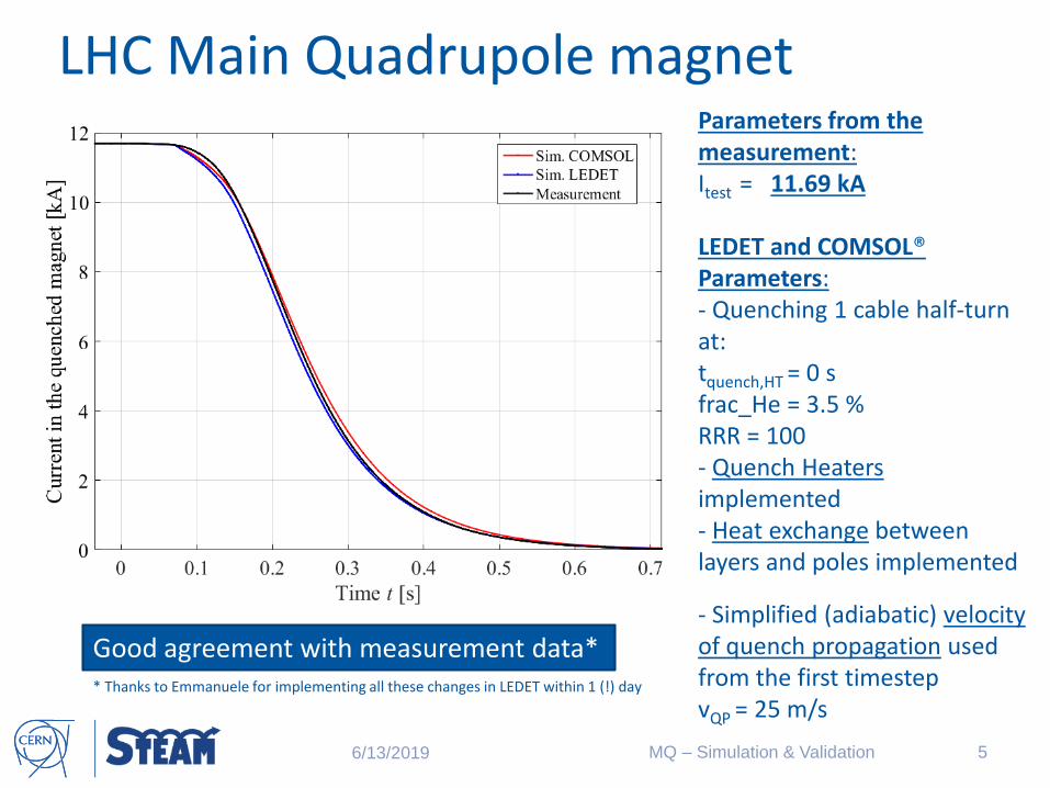
Parameters from the measurement: Itest = 11.69 kA
LEDET and COMSOL®Parameters: - Quenching 1 cable half-turn at: tquench,HT = 0 sfrac_He = 3.5 %RRR = 100- Quench Heaters implemented - Heat exchange between layers and poles implemented
- Simplified (adiabatic) velocity of quench propagation used from the first timestepvQP = 25 m/s
Good agreement with measurement data** Thanks to Emmanuele for implementing all these changes in LEDET within 1 (!) day

LHC Main Quadrupole magnet
6/13/2019 6MQ – Simulation & Validation
Good agreement with measurement data
Parameters from the measurement: Itest = 11.69 kA
LEDET and COMSOL®Parameters: - Quenching 1 cable half-turn at: tquench,HT = 0 sfrac_He = 3.5 %RRR = 100- Quench Heaters implemented - Heat exchange between layers and poles implemented
- Simplified (adiabatic) velocity of quench propagation used from the first timestepvQP = 25 m/s

Electro-thermal model
6/13/2019 MQ – Simulation & Validation 7
COMSOL: 2D – temperature plot at 79 ms
- Quench heaters are start to heat up the coil at 17 ms- it takes 62 ms more to see a significant temperature increase within the 2D plot

Electro-thermal model
6/13/2019 MQ – Simulation & Validation 8
COMSOL: 2D – temperature plot at 153 ms
- After 153 ms the parts without direct Quench Heater contact are heated up by the neighboring half-turns

Electro-thermal model
6/13/2019 MQ – Simulation & Validation 9
COMSOL: 2D – temperature plot at 210 ms
- After 210 ms the entire coil is in normal state

Main quadrupole circuit
6/13/2019 MQ – Simulation & Validation 10
The LHC main quadrupole
circuit:
• power converter (PC)
• energy-extraction (EE)
• main quadrupole magnets
(MQ) and their protection
system
• earthing circuits (EC)• redundant system of sub-
modules within the power converter
• 2 x 8 circuits within the LHC
• within one mechanical
structure two electrical
magnets (RQD/RQF) in two
separate circuits
• redundant system of sub-
modules within the power
converter
Main quadrupole circuit
6/13/2019 MQ – Simulation & Validation 11
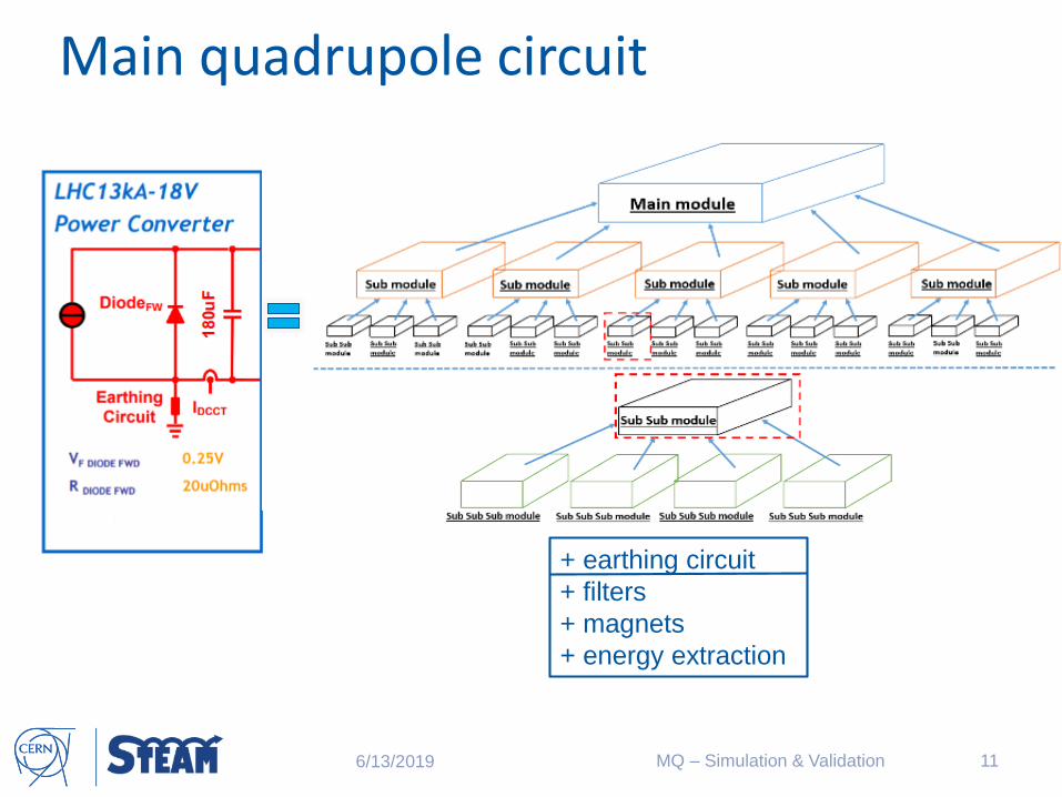
The LHC main quadrupole
circuit:
• power converter (PC)
• energy-extraction (EE)
• main quadrupole magnets
(MQ) and their protection
system
• earthing circuits (EC)
+ earthing circuit
+ filters
+ magnets
+ energy extraction

Main quadrupole circuit – modelling
6/13/2019 MQ – Simulation & Validation 12
Sub-sub-sub module:• Consist of a power supply signal,
two diodes in parallel, resistors and capacitances

Main quadrupole circuit – modelling
6/13/2019 MQ – Simulation & Validation 13
Energy-Extraction System:• Consist of four parallel branches of switches• Parallel to the branches the energy-extraction-resistor is located
• This resistor takes the whole current during the discharge and reduces the time-constant of the discharge.

Main quadrupole circuit – modelling
6/13/2019 MQ – Simulation & Validation 14
All circuit elements has to be:• modelled within PSPICE Netlist• tested independently• Build-up with other parts and tested
Turning off the power supply
Energy-extraction “active”

Main quadrupole circuit – modelling
6/13/2019 MQ – Simulation & Validation 15
All circuit elements has to be:• modelled within PSPICE Netlist• tested independently• Build-up with other parts and tested
Turning off the power supply
Energy-extraction “active”

Co-Simulation of the magnet + circuit
6/13/2019 MQ – Simulation & Validation 16
After the magnet model and the
circuit model are
• generated
• tested
• validated
Co-Simulation of the
combined circuit and magnet
model
What is COSIM?
• Framework based on cooperative
simulation (co-simulation)
• Common coupling interface for
information exchange between several
models
• Advantage:
• complex system is decomposed in
simpler parts
• These parts are simulated by
domain-specific models
• The algorithm ensures consistency
between simulations
Fig. 8: Exchanging information between two ports [8]

Main quadrupole circuit & magnet
6/13/2019 MQ – Simulation & Validation 17
Closer look at the test data from a quench event in 12.2018:IA => Current measured with 1 kHzImeas => Filtered signal of IA (100 Hz)ISim => Simulated current
- Acquisition frequency of 1 kHz is maybe not “enough”
Time constants at the events:LM = 5.6 mH; NM = 47; Rwarm = 0.664404 mW; REE = 6.85 mW
𝝉𝐅𝐏𝐀 = LM∙NM/Rwarm = 396.144 s𝝉𝐄𝐄 = LM∙NM/(Rwarm+ REE) = 35.02 s
Good agreement with measurement data

Main quadrupole circuit & magnet
6/13/2019 MQ – Simulation & Validation 18
Good agreement with measurement data
Closer look at the test data from a quench event in 12.2018:IA => Current measured with 1 kHzImeas => Filtered signal of IA
(100 Hz)ISim => Simulated current
- Acquisition frequency of 1 kHz is maybe not “enough”
Time constants at the events:LM = 5.6 mH; NM = 47; Rwarm = 0.664404 mW; REE = 6.85 mW
𝝉𝐅𝐏𝐀 = LM∙NM/Rwarm = 396.144 s𝝉𝐄𝐄 = LM∙NM/(Rwarm+ REE) = 35.02 s
tFPA
tEE

Main quadrupole circuit & magnet
6/13/2019 MQ – Simulation & Validation 19
Closer look at the test data from a quench event in 12.2018:Current through the diode - starts developing after FPA- Opening voltage (~6V) of
the diode
Time constants at the events:𝝉𝐅𝐏𝐀 = LM∙NM/Rwarm = 396.144 s𝝉𝐄𝐄 = LM∙NM/(Rwarm+ REE) = 35.02 s

6/13/2019 20MQ – Simulation & Validation
Closer look at the simulation results:Resistance of the quenched magnet starts developing before FPA- Magnet quenches 38 ms
before the FPA - Quench heater triggering 3
ms before the FPA
Main quadrupole circuit & magnet

tFPA
tQH,triggertquench
tQH
tEE
6/13/2019 21MQ – Simulation & Validation
Closer look at the simulation results:Resistance of the quenched magnet- starts developing before
FPA- tquench = -0.038 s - tQH,trigger = -0.003 s- tFPA = 0.0 s - tQH = 0.045 s - tEE = 0.102 s
Main quadrupole circuit & magnet
6/13/2019 22MQ – Simulation & Validation
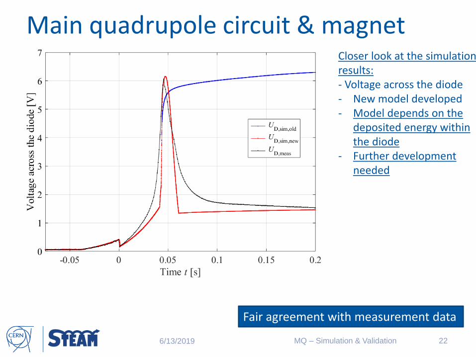
Closer look at the simulation results:- Voltage across the diode - New model developed - Model depends on the
deposited energy within the diode
- Further development needed
Main quadrupole circuit & magnet
Fair agreement with measurement data

tFPA
tQH
tquench
6/13/2019 23MQ – Simulation & Validation
Closer look at the simulation results:- Voltage across the diode - New model developed - Model depends on the
deposited energy within the diode
- Further development needed
Main quadrupole circuit & magnet
Fair agreement with measurement data

6/13/2019 24MQ – Simulation & Validation
Main quadrupole circuit & magnet
hot-spot
half-turn 2
half-turn 3
Closer look at the simulation results:Temperature plot of the hot-spot and his neighbors

Thank you for your attention!
6/13/2019 25MQ – Simulation & Validation

References[1] “Technology Department (TE), 2009 - Present”. Webpage. http://library.cern/archives/history_CERN/internal_organisation/TE. Last visit: 20.02.2019, 06.27 pm.
[2] “TE-MPE Group Page (TE)”. Webpage. https://mpe.web.cern.ch/content/structure/mpe-pe. Last visit: 20.02.2019, 06.48 pm.
[3] “Superconductors”. Presentation. L. Bottura. Magnè, 11.2012.
[4] “Optimization of the Electromagnetic Design of the FCC Sextupoles and Octupoles”. Article in IEEE Transactions on Applied Superconductivity PP(99):1-1. A. Louzguiti et. al. Geneva, 01.2019.
[5] “SIGMA Documentation”. Geneva, 08.2018.
[6] “CLIQ: A new quench protection technologyfor superconducting magnets”. Ph.D. Thesis. E. Ravaioli. Enschede, 2015.
[7] “LHC13kA-18V LHC Main Quadrupole Circuit Power Converter”. Presentation. L. Charnay, V. Montabonnet. Geneva, 2010.
[8] “STEAM Co-Sim – User manual”. Documentation. STEAM team. Geneva, 2018.
[9] “Co-Simulation of Transient Effects in Superconducting Accelerator Magnets”. PhD thesis. M. Maciejewski,. Geneva, 2019.
6/13/2019 26MQ – Simulation & Validation