Embed Size (px)
Citation preview
7/24/2019 Multiplexer and demultiplex by multisim simulations
http://slidepdf.com/reader/full/multiplexer-and-demultiplex-by-multisim-simulations 1/6
MULTIPLEXER & DEMULTIPLEXER
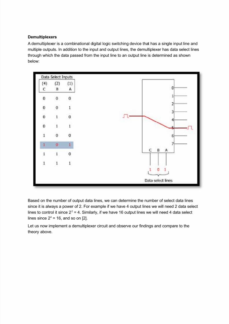
A multiplexer is a combinational digital logic switching device that has multiple inputs and one
output. In addition to the input and output lines, the multiplexer has data select lines through
which the data passed from an input line to the output line is determined as shown below:
Based on the number of input data lines, we can determine the number of the select data lines
since it is always a power of 2. For example if we have input lines we will need 2 data select
lines to control it since 22 ! . "imilarly, if we have #$ input lines we will need data select lines
since 2 ! #$ , and so on.
%et us now implement a multiplexer circuit and observe our findings and compare to the theory
above.
Example Circuit
7/24/2019 Multiplexer and demultiplex by multisim simulations
http://slidepdf.com/reader/full/multiplexer-and-demultiplex-by-multisim-simulations 2/6
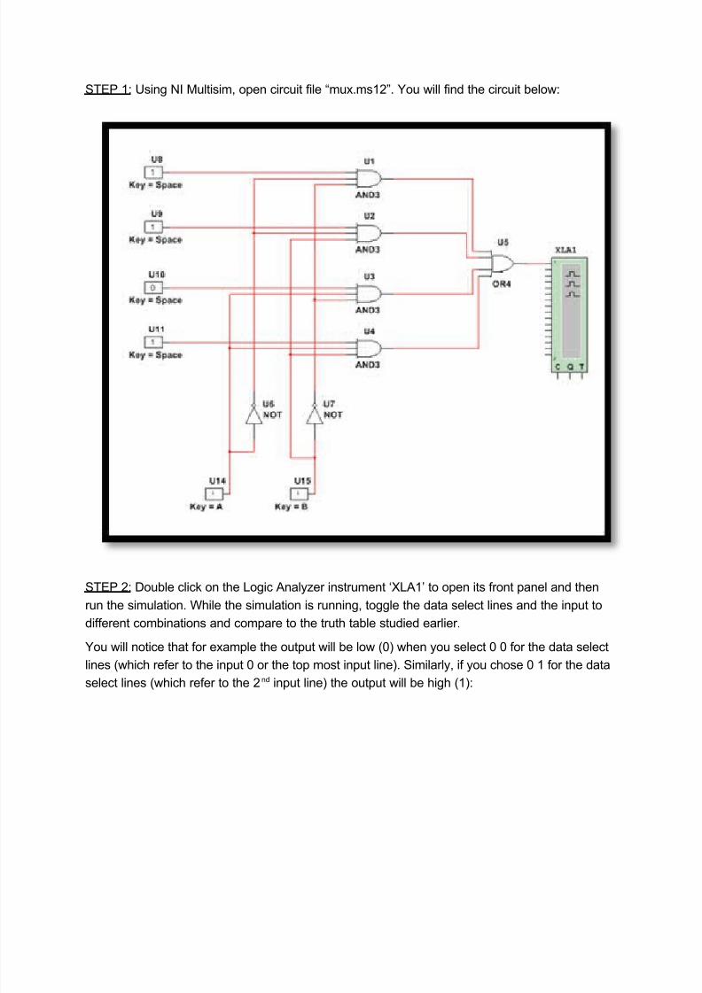
"&'( #: )sing *I +ultisim, open circuit file mux.ms#2-. ou will find the circuit below:
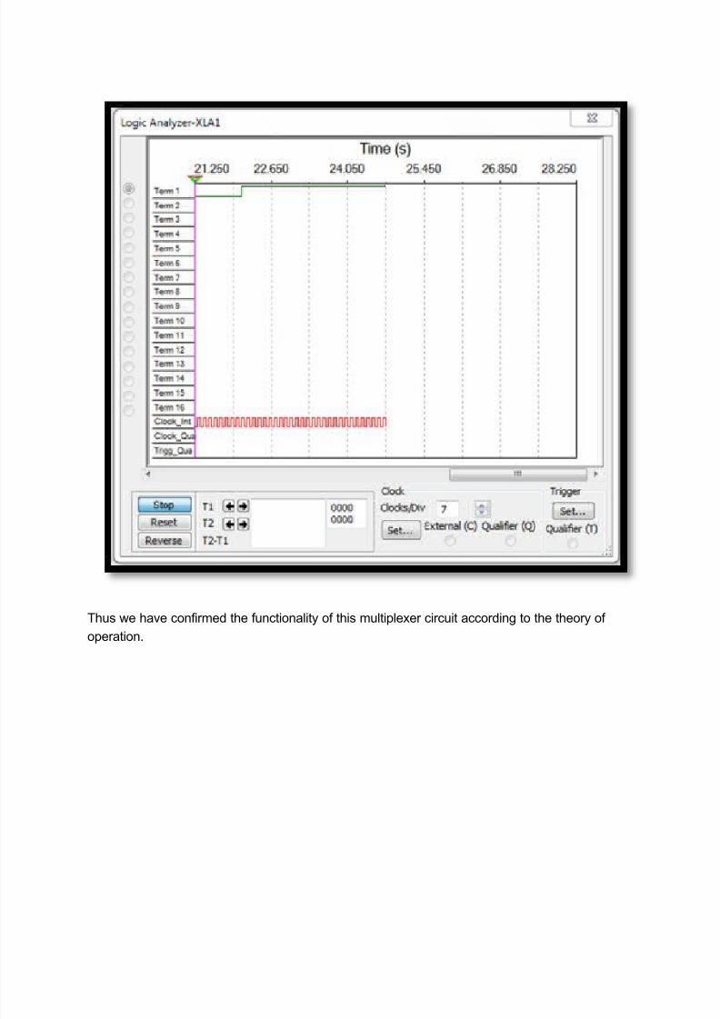
"&'( 2: /ouble clic0 on the %ogic Analy1er instrument 3%A#4 to open its front panel and then
run the simulation. 5hile the simulation is running, toggle the data select lines and the input to
different combinations and compare to the truth table studied earlier.
ou will notice that for example the output will be low 678 when you select 7 7 for the data select
lines 6which refer to the input 7 or the top most input line8. "imilarly, if you chose 7 # for the data
select lines 6which refer to the 2nd input line8 the output will be high 6#8:
7/24/2019 Multiplexer and demultiplex by multisim simulations
http://slidepdf.com/reader/full/multiplexer-and-demultiplex-by-multisim-simulations 3/6
&hus we have confirmed the functionality of this multiplexer circuit according to the theory of
operation.
7/24/2019 Multiplexer and demultiplex by multisim simulations
http://slidepdf.com/reader/full/multiplexer-and-demultiplex-by-multisim-simulations 4/6
7/24/2019 Multiplexer and demultiplex by multisim simulations
http://slidepdf.com/reader/full/multiplexer-and-demultiplex-by-multisim-simulations 5/6
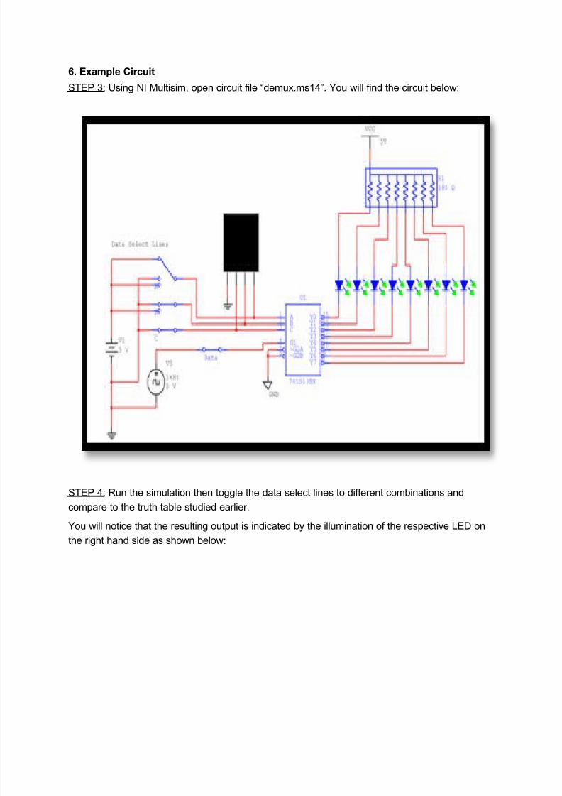
6. Example Circuit
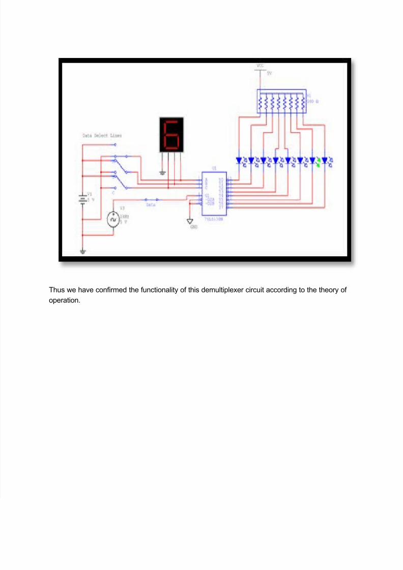
"&'( ;: )sing *I +ultisim, open circuit file demux.ms#-. ou will find the circuit below:
"&'( : <un the simulation then toggle the data select lines to different combinations and
compare to the truth table studied earlier.
ou will notice that the resulting output is indicated by the illumination of the respective %'/ on
the right hand side as shown below:
7/24/2019 Multiplexer and demultiplex by multisim simulations
http://slidepdf.com/reader/full/multiplexer-and-demultiplex-by-multisim-simulations 6/6
&hus we have confirmed the functionality of this demultiplexer circuit according to the theory of
operation.