Embed Size (px)
Citation preview
Multiport Diffusers for Dense DischargesOzeair Abessi, Aff.M.ASCE1; and Philip J. W. Roberts, F.ASCE2
Abstract: Comprehensive laboratory experiments on multiport diffusers for dense effluents such as brine into stationary receiving waters arereported. Tracer concentration fields were mapped in three dimensions by laser-induced fluorescence (3DLIF). The effect of port spacing isdescribed by s=dF where s is the port spacing, d the nozzle diameter, and F the jet densimetric Froude number. For s=dF > ∼2, the jets didnot merge, and the results followed expected asymptotic solutions for single jets. For s=dF < 2 the jets merged, but did not follow expectedasymptotic line source solutions. As the port spacing was reduced, the rise height and other geometrical variables decreased. The dilutionsalso decreased, but much more rapidly than predicted. These were caused by Coanda effects and merging. The Coanda effect caused an underpressure on the interior jet surfaces which caused them to curve more sharply inwards. This shortened their trajectories, reducing the externalsurface area available for entrainment. Jet merging restricted entrainment of clear water to the inner surfaces and exacerbated the Coandaeffect. The implications for numerical modeling are discussed. Integral entrainment models that assume unrestricted entrainment water,neglect reentrainment, and neglect dynamic interaction (Coanda effect) between jets may significantly overestimate dilution. Insight intoport spacing effects can be obtained from studies on positively buoyant jets. To prevent reduction in dilution attributable to restricted entrain-ment, it is recommended to maintain adequate port spacing so that s=dF > ∼2. DOI: 10.1061/(ASCE)HY.1943-7900.0000882. © 2014American Society of Civil Engineers.
Author keywords: Multiport diffuser; Brine disposal; Desalination; Mixing zone; Field study; Outfall; Wastewater disposal.
Introduction
Diffusers with upwardly inclined jets are frequently used to dis-charge wastewaters that have a higher density than the receivingwater. The high exit velocity results in entrainment of ambientwater that can quickly reduce levels of potential contaminants tosafe levels. The main example, which is growing rapidly aroundthe world, is disposal of brine from seawater desalination plants.The primary objective of the diffuser is to reduce salinity to safelevels that have minimal toxic effects on marine biota.
Many studies have been reported on the dynamics and mixing ofinclined dense jets, especially recently. Most have been with singlejets, but multiport diffusers have also been used and are becom-ing more common. Examples are Perth, Sydney, and Melbourne,Australia. The nozzles may discharge perpendicular to the diffuseraxis and be uniformly distributed along either one or both sides ofthe diffuser, or the nozzles may be clustered in rosettes each havingmultiple ports. The Perth diffuser has 40 ports distributed uniformlyalong one side of the diffuser at four meter intervals (Marti et al.2011), the Sydney diffuser has two rosette risers spaced 25 m apart,and each riser has four ports (Tarrade et al. 2010).
Although some hydraulic model tests of specific multiport dif-fusers have been made, no systematic studies of the effect of portspacing have been reported. There are no guidelines to aid in therational design of multiport diffusers and most designs are basedon formulae derived from experiments conducted with single jets.
Therefore, an extensive program of systematic experiments on vari-ous configurations of multiport dense diffusers was undertaken.The experiments were conducted on multiport diffusers with dis-charge from one and both sides and with rosette diffusers. Theexperiments were conducted with and without ambient currentsand the various discharge parameters were systematically variedto cover a range expected for typical ocean outfall diffusers. In thispaper, we report the results of the studies on multiport diffuserswith zero current. The zero current case is of special importanceas it usually assumed as the worst case for design and for meetingenvironmental regulations. The experiments on multiport diffusersin flowing currents and on rosettes will be reported in future papers.
Analysis
Single Jet
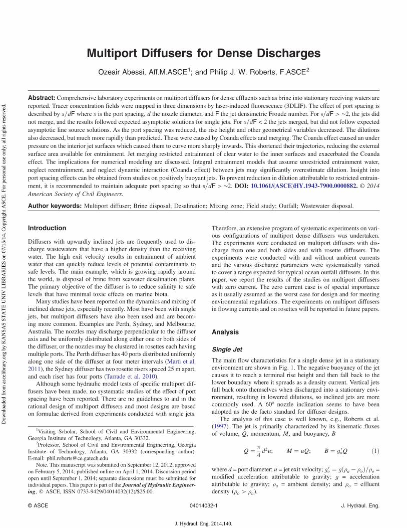
The main flow characteristics for a single dense jet in a stationaryenvironment are shown in Fig. 1. The negative buoyancy of the jetcauses it to reach a terminal rise height and then fall back to thelower boundary where it spreads as a density current. Vertical jetsfall back onto themselves when discharged into a stationary envi-ronment, resulting in lowered dilutions, so inclined jets are morecommonly used. A 60° nozzle inclination seems to have beenadopted as the de facto standard for diffuser designs.
The analysis of this case is well known, e.g., Roberts et al.(1997). The jet is primarily characterized by its kinematic fluxesof volume, Q, momentum, M, and buoyancy, B
Q ¼ π4d2u; M ¼ uQ; B ¼ g 0
oQ ð1Þ
where d = port diameter; u = jet exit velocity; g 0o ¼ gðρa − ρoÞ=ρo =
modified acceleration attributable to gravity; g = accelerationattributable to gravity; ρa = ambient density; and ρo = effluentdensity (ρo > ρa).
1Visiting Scholar, School of Civil and Environmental Engineering,Georgia Institute of Technology, Atlanta, GA 30332.
2Professor, School of Civil and Environmental Engineering, GeorgiaInstitute of Technology, Atlanta, GA 30332 (corresponding author).E-mail: [email protected]
Note. This manuscript was submitted on September 12, 2012; approvedon February 5, 2014; published online on April 1, 2014. Discussion periodopen until September 1, 2014; separate discussions must be submitted forindividual papers. This paper is part of the Journal of Hydraulic Engineer-ing, © ASCE, ISSN 0733-9429/04014032(12)/$25.00.
© ASCE 04014032-1 J. Hydraul. Eng.
J. Hydraul. Eng. 2014.140.
Dow
nloa
ded
from
asc
elib
rary
.org
by
KA
NSA
S ST
AT
E U
NIV
LIB
RA
RIE
S on
07/
15/1
4. C
opyr
ight
ASC
E. F
or p
erso
nal u
se o
nly;
all
righ
ts r
eser
ved.
As discussed in Roberts et al. (1997) and elsewhere, the mostimportant length-scale of the flow is lM ¼ M3=4=B1=2 although thisis essentially equal to and more commonly expressed as dF whereF is the jet densimetric Froude number
F ¼ uffiffiffiffiffiffiffig 0od
p ð2Þ
If the Froude number is greater than approximately 20, thevolume flux Q is not dynamically significant (or, equivalently,the nozzle diameter is not an important length-scale of the flow),Roberts et al. (1997). In that case, any dependent variable, such asthe terminal rise height yt is a function of M and B only
yt ¼ fðM;BÞ ð3Þ
which, following a dimensional analysis leads to
ytdF
¼ Constant ð4Þ
Similar analyses lead to the following expressions for the othermajor jet geometric factors:
ytdF
¼ 2.2;xidF
¼ 2.4;xndF
¼ 9.0;yLdF
¼ 0.7 ð5Þ
and for dilution
SiF¼ 1.6;
SnF
¼ 2.6 ð6Þ
where the values of the constants are taken from Roberts et al.(1997). The variables in Eqs. (5) and (6) are defined in Fig. 1:yt = terminal rise height; xi = location of the jet impact point(and location of the minimum dilution on the lower boundary);xn = length of the near field; yL = thickness of the spreading layer;Si = dilution at the impact point; and Sn = near field dilution(termed the ultimate dilution in Roberts et al. 1997). Eqs. (5)and (6) apply when the jets are fully turbulent, i.e., the jet Reynoldsnumber, R ¼ ud=ν where ν is the kinematic fluid viscosity isgreater than approximately 2,000, and the Froude number is greaterthan approximately 20, when the dynamical effect of the sourcevolume flux becomes negligible.
Multiple Jets
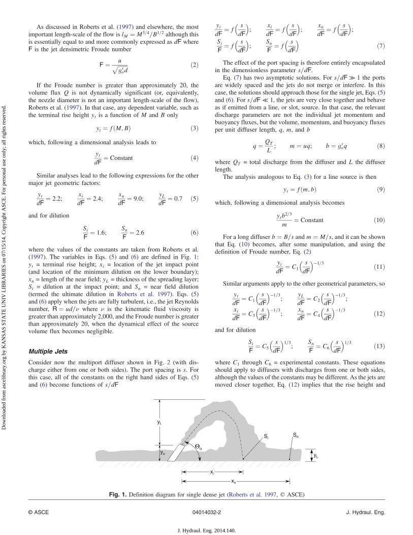
Consider now the multiport diffuser shown in Fig. 2 (with dis-charge either from one or both sides). The port spacing is s. Forthis case, all of the constants on the right hand sides of Eqs. (5)and (6) become functions of s=dF
ytdF
¼ f� sdF
�;
xidF
¼ f� sdF
�;
xndF
¼ f� sdF
�;
SiF¼ f
� sdF
�;
SnF
¼ f� sdF
�ð7Þ
The effect of the port spacing is therefore entirely encapsulatedin the dimensionless parameter s=dF.
Eq. (7) has two asymptotic solutions. For s=dF ≫ 1 the portsare widely spaced and the jets do not merge or interfere. In thiscase, the solutions should approach those for the single jet, Eqs. (5)and (6). For s=dF ≪ 1, the jets are very close together and behaveas if emitted from a line, or slot, source. In that case, the relevantdischarge parameters are not the individual jet momentum andbuoyancy fluxes, but the volume, momentum, and buoyancy fluxesper unit diffuser length, q, m, and b
q ¼ QT
L; m ¼ uq; b ¼ g 0
oq ð8Þ
where QT = total discharge from the diffuser and L the diffuserlength.
The analysis analogous to Eq. (3) for a line source is then
yt ¼ fðm; bÞ ð9Þwhich, following a dimensional analysis becomes
ytb2=3
m¼ Constant ð10Þ
For a long diffuser b ¼ B=s and m ¼ M=s, and it can be shownthat Eq. (10) becomes, after some manipulation, and using thedefinition of Froude number, Eq. (2)
ytdF
¼ C1
� sdF
�−1=3 ð11Þ
Similar arguments apply to the other geometrical parameters, so
ytdF
¼ C1
� sdF
�−1=3;
yLdF
¼ C2
� sdF
�−1=3;
xidF
¼ C3
� sdF
�−1=3;
xndF
¼ C4
� sdF
�−1=3 ð12Þ
and for dilution
SiF¼ C5
� sdF
�1=3
;SnF
¼ C6
� sdF
�1=3 ð13Þ
where C1 through C6 = experimental constants. These equationsshould apply to diffusers with discharges from one or both sides,although the values of the constants may be different. As the jets aremoved closer together, Eq. (12) implies that the rise height and
SnSi
yL
Θο
yt
xi
xn
yo
Fig. 1. Definition diagram for single dense jet (Roberts et al. 1997, © ASCE)
© ASCE 04014032-2 J. Hydraul. Eng.
J. Hydraul. Eng. 2014.140.
Dow
nloa
ded
from
asc
elib
rary
.org
by
KA
NSA
S ST
AT
E U
NIV
LIB
RA
RIE
S on
07/
15/1
4. C
opyr
ight
ASC
E. F
or p
erso
nal u
se o
nly;
all
righ
ts r
eser
ved.
other geometrical parameters increase, and Eq. (13) implies that thedilution decreases.
We would expect a transition between the single jet solutions(s=dF ≫ 1) and line jet solutions (s=dF ≪ 1) to occur at s=dF ∼Oð1Þ). Systematic experiments were performed to test these hy-potheses and to investigate the nature of these relationships.
Previous Multiport Diffuser Studies
Some physical model and field studies have been reported on multi-port brine diffusers. Miller et al. (2006) report physical model stud-ies for the Perth (stage 2) diffuser. Tests were conducted with oneand three ports discharging to one side in stagnant waters. Watersamples were extracted at various locations including near the im-pact point and dilution was measured from sample conductivity.These results are included in the next section. Tarrade et al. (2010)and Miller and Tarrade (2010) reported physical model tests on theSydney and Melbourne rosette diffusers. These results will be dis-cussed further in future papers on rosette diffusers. They reportedthat risers with six ports had lower dilution than with four portsbecause the jets competed for clear water to entrain. With six risersthe entrainment was primarily from above, and dilution was
additionally reduced if the tops of the jets were close to the watersurface. Marti et al. (2011) reported the results of field studies onthe multiport Stage 1 Perth diffuser. Dilutions were found to agreewith the single jet equations, Eq. (6).The results of these studies arecompared with the present results in the sections that follow. Therehave been no systematic studies of spacing effect, however, hencethe need for the present study.
Experiments
Instrumentation
A three-dimensional laser-induced fluorescence system (3DLIF)was used to measure the spatial evolution of the mixing processesand dilution. The experiments were performed in the environmen-tal fluid mechanics laboratory at the Georgia Institute of Tech-nology in a tank with glass walls 6.10 m long × 0.91 mwide×0.61 mdeep.
The 3DLIF system has been described in several publications,for example, Gungor and Roberts (2009), and the experimentalconfiguration is the same as shown in Fig. 3 of that paper exceptthat the diffuser models are multiport diffusers. The only changefrom the previous 3DLIF system is that the camera is an upgradeddigital charge-coupled device (CCD) camera, Imperx Bobcat ICL-B0620M digital camera (Imperx, Boca Raton, Florida) with640 × 480 pixels. In the present experiments, the width of theframe (the field of view) was approximately 750 mm, thereforethe pixel resolution is 750=640 ¼ 1.2 mm. The camera was oper-ated in 8-bit (256 gray levels) mode for which the maximum im-aging rate is 260 frames=s. The images were streamed to an IOIndustries DVR Express Core storage device (IO Industries,London, Ontario) and then to a PC hard drive for further analyses.
The system consists of two fast scanning mirrors that drive thebeam from an Argon-Ion laser (Coherent, Santa Clara, California)through the flow in a programmed pattern. The mirrors create avertical light sheet approximately one mm wide that is swept hori-zontally through the flow at high speed. The system is controlledby two computers, one for overall timing control, and one for im-age capture. A small amount of a fluorescent dye (Rhodamine 6G)is added to the inflow. The laser causes the dye to fluoresce, andthe emitted light is captured by the CCD camera. The first mirror
Fig. 2. Multiport dense effluent diffuser
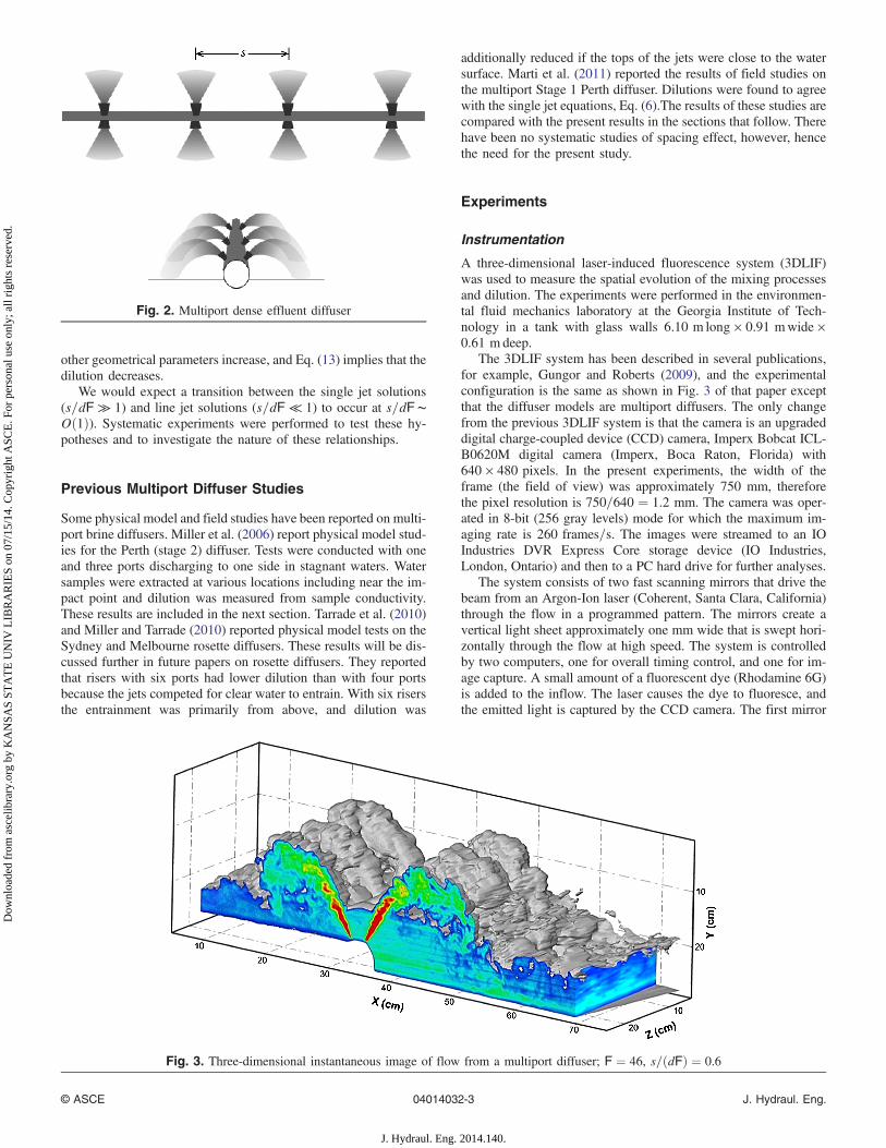
Fig. 3. Three-dimensional instantaneous image of flow from a multiport diffuser; F ¼ 46, s=ðdFÞ ¼ 0.6
© ASCE 04014032-3 J. Hydraul. Eng.
J. Hydraul. Eng. 2014.140.
Dow
nloa
ded
from
asc
elib
rary
.org
by
KA
NSA
S ST
AT
E U
NIV
LIB
RA
RIE
S on
07/
15/1
4. C
opyr
ight
ASC
E. F
or p
erso
nal u
se o
nly;
all
righ
ts r
eser
ved.
sweeps the beam down and up while the camera is exposing(i.e., the shutter is open). The second mirror then moves the beama small distance horizontally, the previous frame is downloaded,the camera buffer cleared, and the next exposure begins. This isrepeated so that multiple vertical slices through the flow are ob-tained. After a predetermined number of slices the beam returns tothe starting point and the cycle starts again. The experimentalparameters were varied to optimize them for each experimentbut a typical imaging rate was 100 frames per second, with 40vertical slices spaced approximately seven mm apart.
The images were corrected pixel-by-pixel for sensor responseand laser attenuation through the clear water, dye, and salt. Theaccuracy of the dilution measurements thus obtained is approxi-mately �10% (Tian 2002). Finally, the multiple slices throughthe flow field are regenerated, using image processing techniques,into three-dimensional images of the flow field.
The general experimental procedures are similar to those inGungor and Roberts (2009) and the method of extracting tracerconcentrations from the images are discussed in detail in Tian andRoberts (2003). The receiving water was uniform density fresh-water that was dechlorinated and filtered to improve clarity. Theeffluent consisted of dechlorinated water with the addition of salt(NaCl) for density control and Rhodamine 6G fluorescent dye as atracer. The dye concentration in the brine source was 100 μg=l andconcentrations measured in the diluted jet were typically of order 1to 10 μg=l. Before each experiment and after the tow tank had beenfilled, two rectangular cylinders containing known dye concentra-tions were placed at the left and right extents of the field of viewand images obtained. This was repeated for several known dye con-centrations. The relationship between dye concentration and pixelresponse (a digital number that ranges from 0 to 255) is linear andthe slope was obtained by a linear regression fit to the data. Theattenuation coefficient for the clear water was obtained from thedecrease in fluorescence intensity measured by the two cells placeda known distance apart. The spatial scale (magnification factor) wasobtained by imaging a ruler placed on the central laser sheet plane,and the scale for off-center images was obtained by simple geomet-ric relationships (Tian 2002).
Hydraulic Modeling Considerations
The model diffusers consisted of 1, 4, 7, or 22 nozzles dischargingto one or both sides of the diffuser. For the experiments with onenozzle, the port diameter, d, was 3.25 mm, for four and seven portsit was 1.93 mm, and for 22 ports it was 2.79 mm.
The ports consisted of short straight pipe stubs. The 22, 7, and 4port diffusers were manifold pipes extending across the channelwith ports extending upwards at 60° (similar to the sketch in Fig. 2).The single port diffuser was a length of copper tubing bent over atthe end with a final upward inclination of 60°. The 22 port diffuserhad ports on both sides, and the 7, 4, and 1 port diffusers dischargedon one side. The 4-port diffuser was the 7-port diffuser with 3 portsblanked off. The lengths, l, of the straight portions of the nozzlesranged from 0.9 to 1.5 cm, so 3 < l=d < 6.
The distance from the channel walls to the end ports is s=2 sothe walls are planes of symmetry between ports. The experimentsthen represent the central section of an infinitely long diffuser,which is an often-used approximation for long diffusers [for exam-ple, Isaacson et al. (1983)]. The single jet experiments represent aone-sided diffuser with a large port spacing that is taken as equal tothe tank width. The emphasis of the experiments was on multiportdiffusers with significant merging effects, i.e., s=dF < 2, as themore widely spaced (i.e., single) jet results were presumed to bewell known.
The nozzle height yo above the floor ranged from 2.6 to 3.2 cmso yo=dF ≪ 1. The port height was therefore much less than therise height and the length of the jet trajectory and so would not beexpected to significantly affect the impact or near field dilutions.
The water depth for all experiments was approximately 40 cm,well above the tops of the jets and no influence of the free surfacewas observed. This is borne out by studies of Jiang et al. (2012) andother experiments that we have conducted (to be submitted) oninfluences of shallow conditions on flow mixing and trajectoryfor 30°, 45°, and 60° jets. For 60° jets we found no surface influencefor dF=H < 0.5 in which H is the water depth. All of the presentexperiments were conducted for dF=H < 0.5.
The experimental data sets consist of millions of sample points,each one sampled at approximately 2.5 Hz. In these experimentsapproximately 60–120 s was required for the flows to establish,and then approximately 90 s for data acquisition which allowedstable averages over the turbulent fluctuations. This leads to datafiles of several gigabytes for each experiment, and considerableprocessing and computer graphics are needed to analyze and visu-alize the results.
The experimental conditions and results are summarized indimensionless form in Table 1. The experimental parameters werechosen to encompass a wide range typical of those expected foroceanic brine diffusers: 12 < F < 100, and 0.44 < s=dF < 12. Allexperiments were conducted with nozzles oriented upwards at60° to the horizontal. Jet Reynolds numbers ranged from approx-imately 840 to 9,300. The jets were observed to be turbulent or toquickly become turbulent after entering the tank. For full details ofthe experiments see Roberts and Abessi (2012).
Experimental Results
General Observations
For each experiment, the tracer concentration at each pixel in everyslice was computed using the procedures outlined previously. The40 slices from one set of horizontal scan constitutes a 3D tracerconcentration field with measurements at approximately 12 millionpoints through the flow collected over 0.4 s. Iso concentration lev-els and concentration contours on planes through the flow are thencomputed and the results visualized in three dimensions usingTecPlot software (http://www.tecplot.com) so the results can bevisualized in three dimensions. A typical instantaneous three-dimensional image of the flow generated in this way from a multi-port diffuser is shown in Fig. 3. For this example, the jets are quiteclosely-spaced (s=dF ¼ 0.6) and the discharge is from both sidesof the diffuser. The outer surface of the flow is visualized by a grayisoconcentration surface set at a low threshold value. Tracer con-centration levels are shown in false-color contours through twovertical planes, one parallel to the current direction through thecenterlines of two opposing jets (an x-y plane), and one down-stream parallel to the diffuser axis (a y-z plane). For these exam-ples, the diffuser consisted of 22 ports, eleven on each side.Only the central three pairs of ports are shown. We also generatesimilar images from sequential scans and combine them to makeflow animations which are available, along with raw data sets, fromthe authors.
The image of Fig. 3 is typical of a turbulent dense jet. Theconcentration field is patchy, with locally steep concentration gra-dients. Concentrations at a point fluctuate widely with instantane-ous values that can be considerably higher than time-averagedvalues. The upper surface of the bottom spreading layer is initiallycharacterized by entraining vortices that collapse at some distance
© ASCE 04014032-4 J. Hydraul. Eng.
J. Hydraul. Eng. 2014.140.
Dow
nloa
ded
from
asc
elib
rary
.org
by
KA
NSA
S ST
AT
E U
NIV
LIB
RA
RIE
S on
07/
15/1
4. C
opyr
ight
ASC
E. F
or p
erso
nal u
se o
nly;
all
righ
ts r
eser
ved.

from the impact point, leaving it undulating with internal waves.The location where the turbulence and vortices collapse marksthe end of the near field. For further discussion of the definitionof near field and its relationship to turbulence collapse, see Robertset al. (1997).
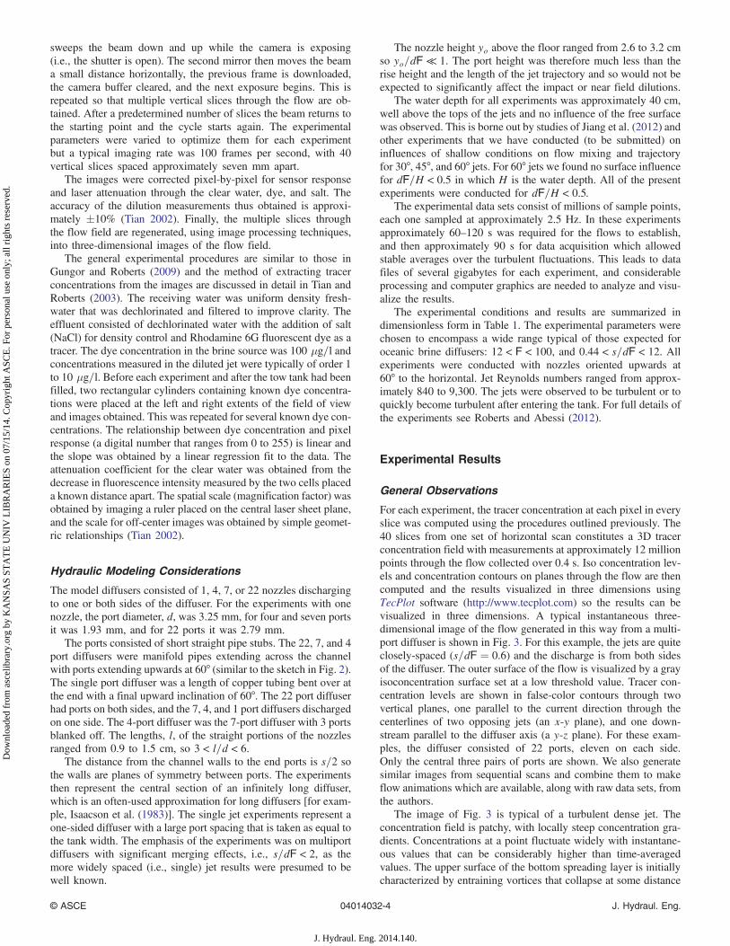
The instantaneous tracer concentrations obtained over the dura-tion of one experiment at each pixel were then time-averaged toremove the turbulent fluctuations. A three-dimensional visualiza-tion of the averaged results for the flow of Fig. 3 is shown in Fig. 4.
The outer surface is again shown as a gray isoconcentration surface,whose level is approximately 10% of the maximum centerline con-centration in the jet at its maximum rise height. In the time-averageimages, tracer concentrations vary smoothly in space but thesetime-averages do not really exist in nature. They are artifacts of theaveraging process.
Time-averaged tracer concentration profiles in planes perpen-dicular to the current (y-z planes) at various downstream distancesare shown in a different way in Fig. 5. Here, the concentrations are
Table 1. Summary of Experiments
F s=ðdFÞ yt=ðdFÞ xi=ðdFÞ Si=F xn=ðdFÞ Sn=F IDNumberof ports
Numberof sides
15.7 1.74 2.19 2.97 1.59 9.02 1.99 31 Jan-Exp01 22 Two25.5 1.07 1.83 2.16 1.07 6.05 1.19 31 Jan-Exp02 22 Two15.7 1.74 2.39 — — — — 31 Jan-Exp03 22 Two12.0 2.27 2.39 2.63 1.98 — 2.45 1 Feb-Exp01 22 Two24.0 1.13 1.90 2.57 1.12 — 1.30 1 Feb-Exp02 22 Two36.0 0.76 1.53 — — — — 1 Feb-Exp03 22 Two17.0 1.61 2.38 2.91 1.28 8.67 — 2 Feb-Exp02 22 Two33.9 0.81 1.66 1.79 0.51 — — 2 Feb-Exp03 22 Two44.1 0.62 1.53 1.70 — — — 2 Feb-Exp04 22 Two15.7 1.74 1.97 — 1.33 — — 6 Feb-Exp01 22 Two19.6 1.39 1.90 2.26 — — — 6 Feb-Exp02 22 Two33.9 0.81 1.66 1.48 0.46 — — 8 Feb-Exp01 22 Two44.1 0.62 1.51 1.30 0.36 — — 8 Feb-Exp02 22 Two49.2 0.55 1.58 1.34 0.37 — — 8 Feb-Exp03 22 Two61.0 0.44 1.37 1.38 0.28 — — 8 Feb-Exp04 22 Two36.0 0.76 1.66 1.64 0.57 5.18 0.69 10 Feb-Exp01 22 Two48.0 0.57 1.62 1.34 0.34 — 0.52 10 Feb-Exp02 22 Two27.1 1 1.95 2.24 0.76 — 0.85 14 Feb-Exp01 22 Two33.9 0.81 1.63 — 0.59 4.75 0.70 14 Feb-Exp03 22 Two21.1 15.47 — 2.78 1.55 13.02 2.53 30 Jul-Exp01 2 Two15.8 20.63 — 2.92 1.69 13.73 2.48 30 Jul-Exp05 2 Two23.7 13.75 — 2.74 1.64 15.37 2.61 30 Jul-Exp06 2 Two29.0 11.25 — 2.84 1.64 12.37 2.61 30 Jul-Exp07 2 Two17.3 1.7 2.64 2.74 1.80 11.00 2.26 16 Feb-Exp01 7 One34.7 0.85 1.75 2.01 0.75 6.70 0.96 16 Feb-Exp02 7 One52.0 0.57 1.60 1.73 0.50 — 0.68 16 Feb-Exp03 7 One63.1 0.47 1.67 1.72 0.39 4.76 0.56 16 Feb-Exp04 7 One56.8 0.52 1.63 1.77 0.51 4.92 0.58 16 Feb-Exp05 7 One63.1 0.47 — 1.72 0.41 4.84 0.58 16 Feb-Exp06 7 One110.4 0.53 1.23 1.66 0.46 — — 16 Feb-Exp07 4 One62.9 0.94 1.86 1.89 0.83 6.17 0.93 16 Feb-Exp08 4 One56.8 1.04 1.89 1.82 0.66 5.37 1.17 21 Feb-Exp01 4 One34.8 1.7 1.94 — — — — 21 Feb-Exp03 4 One77.3 0.76 1.63 1.93 0.83 4.29 0.80 21 Feb-Exp04 4 One99.3 0.59 1.40 1.82 0.79 — — 21 Feb-Exp05 4 One81.1 0.73 1.54 1.93 0.79 3.96 0.91 21 Feb-Exp06 4 One63.1 0.93 1.76 1.80 0.99 — — 21 Feb-Exp07 4 One27.0 2.19 2.10 2.39 — 8.62 — 21 Feb-Exp09 4 One18.0 3.28 2.37 2.80 — — 3.08 21 Feb-Exp10 4 One24.5 4.39 2.14 2.47 1.70 — — 23 Feb-Exp01 1 One39.2 7.14 2.00 2.78 1.82 — — 23 Feb-Exp02 1 One49.0 5.71 — 2.75 1.85 — — 23 Feb-Exp03 1 One24.5 11.43 2.17 2.66 2.04 — 2.55 23 Feb-Exp04 1 One19.6 3.14 2.27 3.06 1.62 10.30 2.55 23 Feb-Exp05 1 One29.4 9.52 2.00 3.08 1.21 — — 23 Feb-Exp06 1 One34.3 8.16 2.00 2.87 — — — 23 Feb-Exp07 1 One44.1 6.35 — 2.57 — — 2.16 23 Feb-Exp08 1 One60.0 4.66 — 2.77 1.45 — 3.33 28 Feb-Exp01 1 One48.0 5.83 — 2.98 1.54 — — 28 Feb-Exp02 1 One36.0 7.77 1.98 3.03 1.54 — — 28 Feb-Exp03 1 One24.0 11.66 2.33 2.88 1.73 11.53 3.20 28 Feb-Exp04 1 One30.0 9.33 2.11 2.94 1.48 8.41 3.17 28 Feb-Exp05 1 One42.0 5.12 1.94 2.82 1.75 7.25 3.17 28 Feb-Exp06 1 One54.0 3.98 1.97 2.70 1.45 7.88 2.54 28 Feb-Exp07 1 One
© ASCE 04014032-5 J. Hydraul. Eng.
J. Hydraul. Eng. 2014.140.
Dow
nloa
ded
from
asc
elib
rary
.org
by
KA
NSA
S ST
AT
E U
NIV
LIB
RA
RIE
S on
07/
15/1
4. C
opyr
ight
ASC
E. F
or p
erso
nal u
se o
nly;
all
righ
ts r
eser
ved.
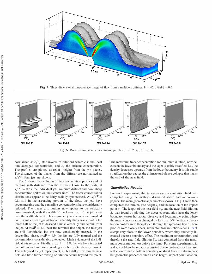
normalized as c=co (the inverse of dilution) where c is the localtime-averaged concentration, and co the effluent concentration.The profiles are plotted as relief (height) from the y-z planes.The distances of the planes from the diffuser are normalized asx=dF. Four jets are shown.
Fig. 5 shows the evolution of the concentration profiles and jetmerging with distance from the diffuser. Close to the ports, atx=dF ¼ 0.23, the individual jets are quite distinct and have sharpconcentration spikes on their center lines. The tracer concentrationdistributions appear to be fairly radially symmetrical. At x=dF ¼0.8, still in the ascending portion of the flow, the jets havebegun merging and the centerline concentrations have considerablyreduced. The tracer distributions now appear to be verticallyunsymmetrical, with the width of the lower part of the jet largerthan the width above it. This asymmetry has been often remarkedon. It results from a gravitational instability that causes fluid in thelower half of the jet to descend almost vertically and detrain fromthe jet. At x=dF ¼ 1.1, near the terminal rise height, the four jetsare still identifiable, but are now considerably merged. In thedescending phase, x=dF ¼ 1.9, the jets are fully merged and theconcentrations considerably attenuated. Little evidence of the indi-vidual jets remains. Finally, at x=dF ¼ 2.8, the jets have impactedthe bottom and are now spreading as a horizontal density current.This is beyond the jet impact point, xi, but still just within the nearfield and little further mixing or dilution occurs beyond this point.
The maximum tracer concentration (or minimum dilution) now oc-curs on the lower boundary and the layer is stably stratified, i.e., thedensity decreases upwards from the lower boundary. It is this stablestratification that causes the ultimate turbulence collapse that marksthe end of the near field.
Quantitative Results
For each experiment, the time-average concentration field wascomputed using the methods discussed above and in previouspapers. The main geometrical parameters shown in Fig. 1 were thencomputed: the terminal rise height yt and the location of the impactpoint xi. The length of the near field xn, and the near field dilutionSn was found by plotting the tracer concentration near the lowerboundary versus horizontal distance and locating the point wherethe mean concentration changed by less than 5%. Vertical concen-tration profiles were then plotted through the spreading layer. Theseprofiles were closely linear, similar to those in Roberts et al. (1997),except very close to the lower boundary where they suddenly in-creased due to a boundary effect. The maximum concentration, andtherefore the near field dilution Sn, was computed from the maxi-mum concentration just before the jump. For some experiments, Snand xn could not be reliably estimated due to problems such as laserreflection from the bottom boundary or slight laser misalignments,but geometric properties such as rise height, impact point location,
Fig. 4. Three-dimensional time-average image of flow from a multiport diffuser; F ¼ 46, s=ðdFÞ ¼ 0.6
Fig. 5. Downstream lateral concentration profiles; F ¼ 52, s=ðdFÞ ¼ 0.6
© ASCE 04014032-6 J. Hydraul. Eng.
J. Hydraul. Eng. 2014.140.
Dow
nloa
ded
from
asc
elib
rary
.org
by
KA
NSA
S ST
AT
E U
NIV
LIB
RA
RIE
S on
07/
15/1
4. C
opyr
ight
ASC
E. F
or p
erso
nal u
se o
nly;
all
righ
ts r
eser
ved.
and length of the near field could. Only values of Sn and xn that wejudged to be reliable are included in Table 1.
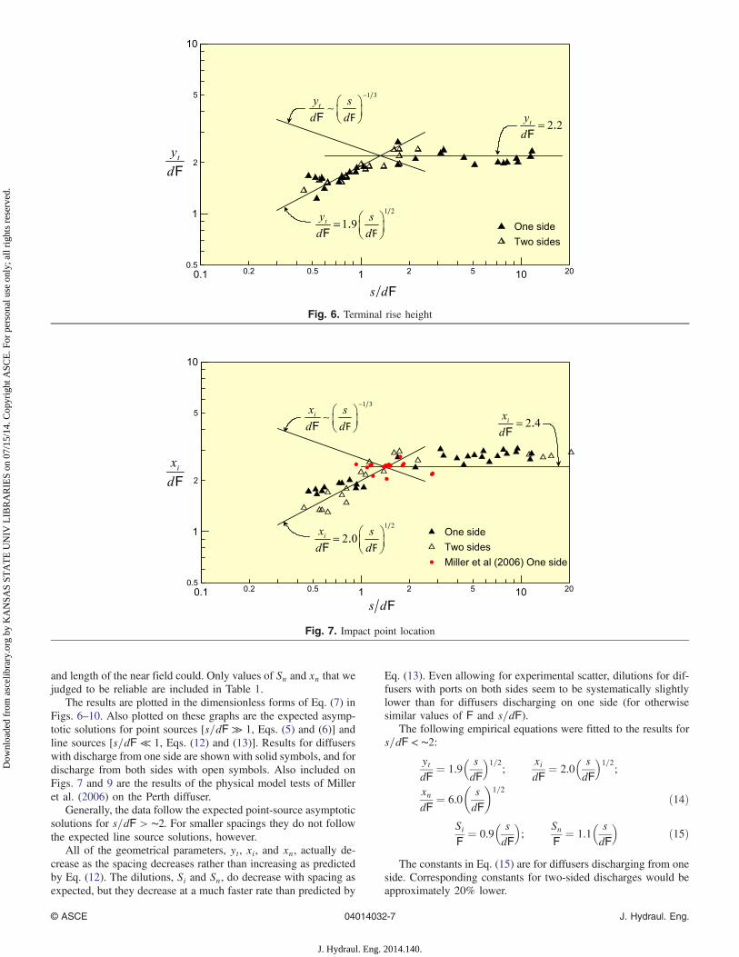
The results are plotted in the dimensionless forms of Eq. (7) inFigs. 6–10. Also plotted on these graphs are the expected asymp-totic solutions for point sources [s=dF ≫ 1, Eqs. (5) and (6)] andline sources [s=dF ≪ 1, Eqs. (12) and (13)]. Results for diffuserswith discharge from one side are shown with solid symbols, and fordischarge from both sides with open symbols. Also included onFigs. 7 and 9 are the results of the physical model tests of Milleret al. (2006) on the Perth diffuser.
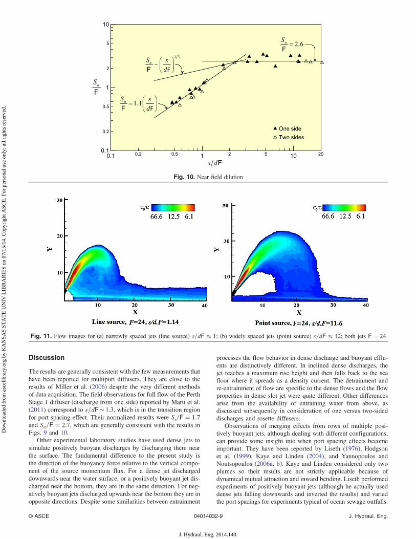
Generally, the data follow the expected point-source asymptoticsolutions for s=dF > ∼2. For smaller spacings they do not followthe expected line source solutions, however.
All of the geometrical parameters, yt, xi, and xn, actually de-crease as the spacing decreases rather than increasing as predictedby Eq. (12). The dilutions, Si and Sn, do decrease with spacing asexpected, but they decrease at a much faster rate than predicted by
Eq. (13). Even allowing for experimental scatter, dilutions for dif-fusers with ports on both sides seem to be systematically slightlylower than for diffusers discharging on one side (for otherwisesimilar values of F and s=dF).
The following empirical equations were fitted to the results fors=dF < ∼2:
ytdF
¼ 1.9� sdF
�1=2
;xidF
¼ 2.0� sdF
�1=2
;
xndF
¼ 6.0
�sdF
�1=2
ð14Þ
SiF¼ 0.9
� sdF
�;
SnF
¼ 1.1� sdF
�ð15Þ
The constants in Eq. (15) are for diffusers discharging from oneside. Corresponding constants for two-sided discharges would beapproximately 20% lower.
Fig. 6. Terminal rise height
Fig. 7. Impact point location
© ASCE 04014032-7 J. Hydraul. Eng.
J. Hydraul. Eng. 2014.140.
Dow
nloa
ded
from
asc
elib
rary
.org
by
KA
NSA
S ST
AT
E U
NIV
LIB
RA
RIE
S on
07/
15/1
4. C
opyr
ight
ASC
E. F
or p
erso
nal u
se o
nly;
all
righ
ts r
eser
ved.
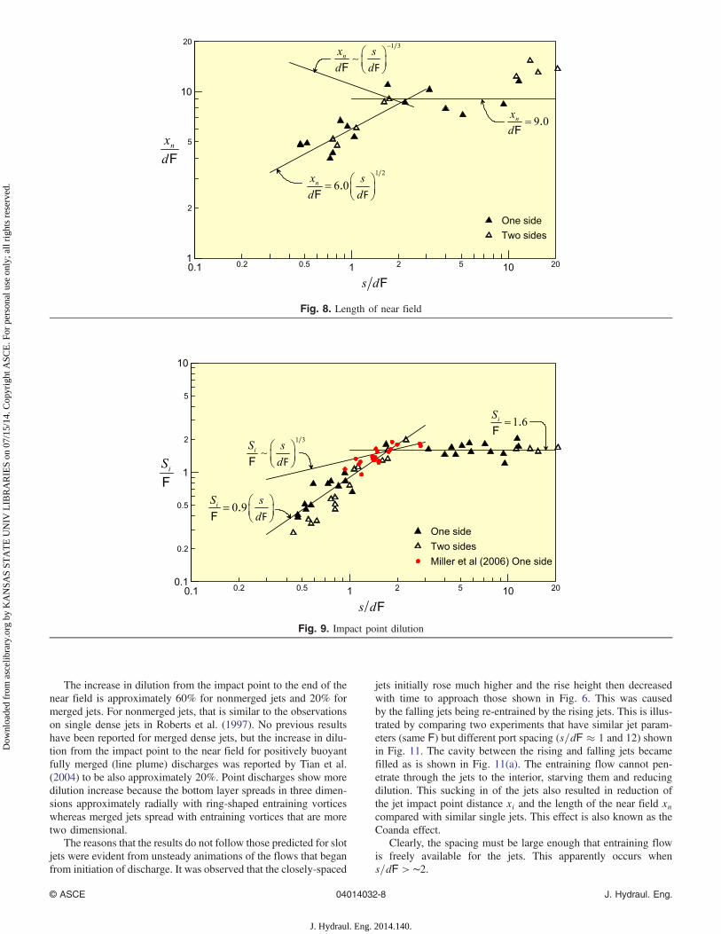
The increase in dilution from the impact point to the end of thenear field is approximately 60% for nonmerged jets and 20% formerged jets. For nonmerged jets, that is similar to the observationson single dense jets in Roberts et al. (1997). No previous resultshave been reported for merged dense jets, but the increase in dilu-tion from the impact point to the near field for positively buoyantfully merged (line plume) discharges was reported by Tian et al.(2004) to be also approximately 20%. Point discharges show moredilution increase because the bottom layer spreads in three dimen-sions approximately radially with ring-shaped entraining vorticeswhereas merged jets spread with entraining vortices that are moretwo dimensional.
The reasons that the results do not follow those predicted for slotjets were evident from unsteady animations of the flows that beganfrom initiation of discharge. It was observed that the closely-spaced
jets initially rose much higher and the rise height then decreasedwith time to approach those shown in Fig. 6. This was causedby the falling jets being re-entrained by the rising jets. This is illus-trated by comparing two experiments that have similar jet param-eters (same F) but different port spacing (s=dF ≈ 1 and 12) shownin Fig. 11. The cavity between the rising and falling jets becamefilled as is shown in Fig. 11(a). The entraining flow cannot pen-etrate through the jets to the interior, starving them and reducingdilution. This sucking in of the jets also resulted in reduction ofthe jet impact point distance xi and the length of the near field xncompared with similar single jets. This effect is also known as theCoanda effect.
Clearly, the spacing must be large enough that entraining flowis freely available for the jets. This apparently occurs whens=dF > ∼2.
Fig. 8. Length of near field
Fig. 9. Impact point dilution
© ASCE 04014032-8 J. Hydraul. Eng.
J. Hydraul. Eng. 2014.140.
Dow
nloa
ded
from
asc
elib
rary
.org
by
KA
NSA
S ST
AT
E U
NIV
LIB
RA
RIE
S on
07/
15/1
4. C
opyr
ight
ASC
E. F
or p
erso
nal u
se o
nly;
all
righ
ts r
eser
ved.
Discussion
The results are generally consistent with the few measurements thathave been reported for multiport diffusers. They are close to theresults of Miller et al. (2006) despite the very different methodsof data acquisition. The field observations for full flow of the PerthStage 1 diffuser (discharge from one side) reported by Marti et al.(2011) correspond to s=dF ∼ 1.3, which is in the transition regionfor port spacing effect. Their normalized results were Si=F ¼ 1.7and Sn=F ¼ 2.7, which are generally consistent with the results inFigs. 9 and 10.
Other experimental laboratory studies have used dense jets tosimulate positively buoyant discharges by discharging them nearthe surface. The fundamental difference to the present study isthe direction of the buoyancy force relative to the vertical compo-nent of the source momentum flux. For a dense jet dischargeddownwards near the water surface, or a positively buoyant jet dis-charged near the bottom, they are in the same direction. For neg-atively buoyant jets discharged upwards near the bottom they are inopposite directions. Despite some similarities between entrainment
processes the flow behavior in dense discharge and buoyant efflu-ents are distinctively different. In inclined dense discharges, thejet reaches a maximum rise height and then falls back to the seafloor where it spreads as a density current. The detrainment andre-entrainment of flow are specific to the dense flows and the flowproperties in dense slot jet were quite different. Other differencesarise from the availability of entraining water from above, asdiscussed subsequently in consideration of one versus two-sideddischarges and rosette diffusers.
Observations of merging effects from rows of multiple posi-tively buoyant jets, although dealing with different configurations,can provide some insight into when port spacing effects becomeimportant. They have been reported by Liseth (1976), Hodgsonet al. (1999), Kaye and Linden (2004), and Yannopoulos andNoutsopoulos (2006a, b). Kaye and Linden considered only twoplumes so their results are not strictly applicable because ofdynamical mutual attraction and inward bending. Liseth performedexperiments of positively buoyant jets (although he actually useddense jets falling downwards and inverted the results) and variedthe port spacings for experiments typical of ocean sewage outfalls.
Fig. 10. Near field dilution
Fig. 11. Flow images for (a) narrowly spaced jets (line source) s=dF ≈ 1; (b) widely spaced jets (point source) s=dF ≈ 12; both jets F ¼ 24
© ASCE 04014032-9 J. Hydraul. Eng.
J. Hydraul. Eng. 2014.140.
Dow
nloa
ded
from
asc
elib
rary
.org
by
KA
NSA
S ST
AT
E U
NIV
LIB
RA
RIE
S on
07/
15/1
4. C
opyr
ight
ASC
E. F
or p
erso
nal u
se o
nly;
all
righ
ts r
eser
ved.
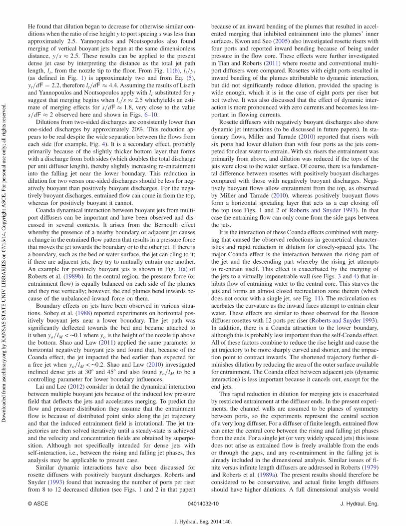
He found that dilution began to decrease for otherwise similar con-ditions when the ratio of rise height y to port spacing swas less thanapproximately 2.5. Yannopoulos and Noutsopoulos also foundmerging of vertical buoyant jets began at the same dimensionlessdistance, y=s ≈ 2.5. These results can be applied to the presentdense jet case by interpreting the distance as the total jet pathlength, lt, from the nozzle tip to the floor. From Fig. 11(b), lt=yt(as defined in Fig. 1) is approximately two and from Eq. (5),yt=dF ¼ 2.2, therefore lt=dF ≈ 4.4. Assuming the results of Lisethand Yannopoulos and Noutsopoulos apply with lt substituted for ysuggest that merging begins when lt=s ≈ 2.5 whichyields an esti-mate of merging effects for s=dF ≈ 1.8, very close to the values=dF ≈ 2 observed here and shown in Figs. 6–10.
Dilutions from two-sided discharges are consistently lower thanone-sided discharges by approximately 20%. This reduction ap-pears to be real despite the wide separation between the flows fromeach side (for example, Fig. 4). It is a secondary effect, probablyprimarily because of the slightly thicker bottom layer that formswith a discharge from both sides (which doubles the total dischargeper unit diffuser length), thereby slightly increasing re-entrainmentinto the falling jet near the lower boundary. This reduction indilution for two versus one-sided discharges should be less for neg-atively buoyant than positively buoyant discharges. For the nega-tively buoyant discharges, entrained flow can come in from the top,whereas for positively buoyant it cannot.
Coanda dynamical interaction between buoyant jets from multi-port diffusers can be important and have been observed and dis-cussed in several contexts. It arises from the Bernoulli effectwhereby the presence of a nearby boundary or adjacent jet causesa change in the entrained flow pattern that results in a pressure forcethat moves the jet towards the boundary or to the other jet. If there isa boundary, such as the bed or water surface, the jet can cling to it;if there are adjacent jets, they try to mutually entrain one another.An example for positively buoyant jets is shown in Fig. 1(a) ofRoberts et al. (1989b). In the central region, the pressure force (orentrainment flow) is equally balanced on each side of the plumesand they rise vertically; however, the end plumes bend inwards be-cause of the unbalanced inward force on them.
Boundary effects on jets have been observed in various situa-tions. Sobey et al. (1988) reported experiments on horizontal pos-itively buoyant jets near a lower boundary. The jet path wassignificantly deflected towards the bed and became attached toit when yo=lM < ∼0.1 where yo is the height of the nozzle tip abovethe bottom. Shao and Law (2011) applied the same parameter tohorizontal negatively buoyant jets and found that, because of theCoanda effect, the jet impacted the bed earlier than expected fora free jet when yo=lM < ∼0.2. Shao and Law (2010) investigatedinclined dense jets at 30° and 45° and also found yo=lM to be acontrolling parameter for lower boundary influences.
Lai and Lee (2012) consider in detail the dynamical interactionbetween multiple buoyant jets because of the induced low pressurefield that deflects the jets and accelerates merging. To predict theflow and pressure distribution they assume that the entrainmentflow is because of distributed point sinks along the jet trajectoryand that the induced entrainment field is irrotational. The jet tra-jectories are then solved iteratively until a steady-state is achievedand the velocity and concentration fields are obtained by superpo-sition. Although not specifically intended for dense jets withself-interaction, i.e., between the rising and falling jet phases, thisanalysis may be applicable to present case.
Similar dynamic interactions have also been discussed forrosette diffusers with positively buoyant discharges. Roberts andSnyder (1993) found that increasing the number of ports per riserfrom 8 to 12 decreased dilution (see Figs. 1 and 2 in that paper)
because of an inward bending of the plumes that resulted in accel-erated merging that inhibited entrainment into the plumes’ innersurfaces. Kwon and Seo (2005) also investigated rosette risers withfour ports and reported inward bending because of being underpressure in the flow core. These effects were further investigatedin Tian and Roberts (2011) where rosette and conventional multi-port diffusers were compared. Rosettes with eight ports resulted ininward bending of the plumes attributable to dynamic interaction,but did not significantly reduce dilution, provided the spacing iswide enough, which it is in the case of eight ports per riser butnot twelve. It was also discussed that the effect of dynamic inter-action is more pronounced with zero currents and becomes less im-portant in flowing currents.
Rosette diffusers with negatively buoyant discharges also showdynamic jet interactions (to be discussed in future papers). In sta-tionary flows, Miller and Tarrade (2010) reported that risers withsix ports had lower dilution than with four ports as the jets com-peted for clear water to entrain. With six risers the entrainment wasprimarily from above, and dilution was reduced if the tops of thejets were close to the water surface. Of course, there is a fundamen-tal difference between rosettes with positively buoyant dischargescompared with those with negatively buoyant discharges. Nega-tively buoyant flows allow entrainment from the top, as observedby Miller and Tarrade (2010), whereas positively buoyant flowsform a horizontal spreading layer that acts as a cap closing offthe top (see Figs. 1 and 2 of Roberts and Snyder 1993). In thatcase the entraining flow can only come from the side gaps betweenthe jets.
It is the interaction of these Coanda effects combined with merg-ing that caused the observed reductions in geometrical character-istics and rapid reduction in dilution for closely-spaced jets. Themajor Coanda effect is the interaction between the rising part ofthe jet and the descending part whereby the rising jet attemptsto re-entrain itself. This effect is exacerbated by the merging ofthe jets to a virtually impenetrable wall (see Figs. 3 and 4) that in-hibits flow of entraining water to the central core. This starves thejets and forms an almost closed recirculation zone therein (whichdoes not occur with a single jet, see Fig. 11). The recirculation ex-acerbates the curvature as the inward faces attempt to entrain clearwater. These effects are similar to those observed for the Bostondiffuser rosettes with 12 ports per riser (Roberts and Snyder 1993).In addition, there is a Coanda attraction to the lower boundary,although this is probably less important than the self-Coanda effect.All of these factors combine to reduce the rise height and cause thejet trajectory to be more sharply curved and shorter, and the impac-tion point to contract inwards. The shortened trajectory further di-minishes dilution by reducing the area of the outer surface availablefor entrainment. The Coanda effect between adjacent jets (dynamicinteraction) is less important because it cancels out, except for theend jets.
This rapid reduction in dilution for merging jets is exacerbatedby restricted entrainment at the diffuser ends. In the present experi-ments, the channel walls are assumed to be planes of symmetrybetween ports, so the experiments represent the central sectionof a very long diffuser. For a diffuser of finite length, entrained flowcan enter the central core between the rising and falling jet phasesfrom the ends. For a single jet (or very widely spaced jets) this issuedoes not arise as entrained flow is freely available from the endsor through the gaps, and any re-entrainment in the falling jet isalready included in the dimensional analysis. Similar issues of fi-nite versus infinite length diffusers are addressed in Roberts (1979)and Roberts et al. (1989a). The present results should therefore beconsidered to be conservative, and actual finite length diffusersshould have higher dilutions. A full dimensional analysis would
© ASCE 04014032-10 J. Hydraul. Eng.
J. Hydraul. Eng. 2014.140.
Dow
nloa
ded
from
asc
elib
rary
.org
by
KA
NSA
S ST
AT
E U
NIV
LIB
RA
RIE
S on
07/
15/1
4. C
opyr
ight
ASC
E. F
or p
erso
nal u
se o
nly;
all
righ
ts r
eser
ved.
include the diffuser length as a variable and it would be expectedthat the results would asymptotically approach the present ones asthe diffuser length increased. We could not readily do this type ofexperiment here, however.
A true slot jet extending across the channel would be a specialcase. There would be no gaps between the jets or at the ends fromwhich entrainment flow could be supplied to the inner core ofthe rising/falling jet. The increased initial rise height was clearlyobserved in the experiments, but we did not do systematic experi-ments to quantify this effect or confirm the initial transient analyseswhere a slot dense jet could be expected to follow the proposed 1=3and −1=3 laws [Eqs. (12) and (13)].
These observations have implications for modeling multiportdiffusers. Most entrainment models assume a freely-availablesource of entraining flow and neglect dynamic interaction andre-entrainment. Clearly, these assumptions are violated for themerging jets studied here, indicating that entrainment modelswould overestimate dilution and geometries for these flows.Dynamical interaction could be modeled by techniques such asthe distributed sink approach of Lai and Lee (2012) or by physicalmodel studies.
Other parameters in the field not considered here could also in-fluence the results. For example, seabed slope would accelerate thebottom gravity current and make it thinner. This would probablyincrease dilution compared with the present results so the horizon-tal bed should be considered a worst case for dilution. Bed formscould also have an effect but these are beyond the scope of thepresent study whose objectives were to investigate the basic influ-ences of jet spacing on dense effluent mixing.
Conclusions
Comprehensive laboratory experiments were conducted on multi-port diffusers similar to those used to discharge brine concentratefrom seawater desalination back into the ocean. Tracer concentra-tion fields were mapped in three dimensions by laser-induced fluo-rescence (3DLIF). The discharges were from one or both sidesof the diffuser and the ports were inclined upwards at 60° as iscommon design practice. The port spacing and other parameterswere varied to cover conditions expected to be typical of oceanicdiffusers. Experiments with and without currents have been per-formed; in this paper we report the results for stationary receivingwaters.
The effect of port spacing is described by the dimensionlessparameter s=dF where s is the port spacing, d the nozzle diameter,and F the jet densimetric Froude number. Normalized expressionswere derived for rise height and other geometrical properties andfor the dilutions at the impact point and end of near field. Two limit-ing asymptotic solutions were obtained. For s=dF ≫ 1 the flowsapproach those of single jets, and for s=dF ≪ 1 the flows approachthose attributable to line, or slot, sources. The variations of the mea-sured normalized variables with s=dF were investigated and com-pared with these asymptotic solutions.
It was found that for s=dF > ∼2 the jets did not merge and thegeometrical and dilution results followed the expected asymptoticresults for single jets. For s=dF < ∼2 the jets merged, but did notfollow the expected line source solutions. Instead of the rise heightand other geometrical variables increasing with decreased portspacing, they actually decreased. The dilutions decreased, as ex-pected; however, they decreased much more rapidly than predictedas the spacing decreased.
The reasons for these results for closely spaced jets were appar-ent from flow visualizations and animations of their transient
behavior. They were attributable to Coanda effects combined withmerging. The Coanda effect caused an under pressure on theinterior jet surfaces which caused their trajectories to curve inwardsmore sharply and contract. This caused re-entrainment of thedescending jets by their ascending portions. It also shortenedthe jet trajectories, reducing the external surface area availablefor entrainment. The jet merging resulted in an almost impenetrablewall, preventing clear water from reaching the inner surfaces andexacerbated the Coanda effect as the inner surfaces attempted toentrain clear water. The jets also experience a Coanda attractionfrom the lower boundary, but this is probably less important thanthe self-Coanda effect.
Dilutions for discharges from two sides were approximately20% less than for discharges from one side (for otherwise similarvalues of F and s=dF) in stationary currents.
It was observed that the merged jets initially rose much higherthan their ultimate levels and it is possible that the asymptotic linesource solutions apply to the maximum rise heights and otherparameters in this transient phase.
The results have significant implications for numerical model-ing of multiport diffusers for dense jets. Integral entrainment mod-els usually assume an unrestricted supply of entrainment water,neglect re-entrainment, and neglect dynamic interaction (Coandaeffect) between jets. All of these conditions are violated for themerged jets observed here and integral models would probably con-siderably overestimate dilutions. These deficiencies of entrainmentmodels may be alleviated by including dynamic interaction such asby the distributed sink approach of Lai and Lee (2012). Computa-tional fluid dynamics (CFD) would also be very challenging as theentire flow field and restricted entrainment must be modeled.Physical modeling may be needed to predict these effects for com-plex diffuser geometries with multiple jets, for example, Miller andTarrade (2010), Tarrade et al. (2010).
To prevent the reduction in dilution attributable to restrictedentrainment, it is necessary to design multiport diffusers so thatthe jets are sufficiently separated. To accomplish this it is recom-mended to maintain s=dF > ∼2.
Acknowledgments
The authors are indebted to Varun Ghandi for his help in conduct-ing the laboratory experiments, Andy Udell for constructing themodel diffusers, and the U.S. Bureau of Reclamation for financialsupport.
Notation
The following symbols are used in this paper:B = jet buoyancy flux;b = jet buoyancy flux per unit diffuser length;c = tracer (Rhodamine 6G) concentration;co = source tracer concentration;d = port diameter;F = jet densimetric Froude number = u=
ffiffiffiffiffiffiffig 0od
p;
g = acceleration attributable to gravity;g 0o = modified acceleration attributable to
gravity = gðρa − ρoÞ=ρo;H = water depth;L = diffuser length;l = length of straight portion of nozzles;
lM = length scale = M3=4=B1=2;lt = length of dense jet trajectory from nozzle to floor;M = jet momentum flux;
© ASCE 04014032-11 J. Hydraul. Eng.
J. Hydraul. Eng. 2014.140.
Dow
nloa
ded
from
asc
elib
rary
.org
by
KA
NSA
S ST
AT
E U
NIV
LIB
RA
RIE
S on
07/
15/1
4. C
opyr
ight
ASC
E. F
or p
erso
nal u
se o
nly;
all
righ
ts r
eser
ved.
m = jet momentum flux per unit diffuser length;Q = jet volume flux;QT = total wastewater flow rate;q = jet volume flux per unit diffuser length;R = Jet Reynolds number = R ¼ ujd=ν;S = local dilution;Si = impact point dilution;Sn = near field dilution;u = jet exit velocity;xi = location of jet impact point (Fig. 1);xn = length of near field (Fig. 1);yo = height of nozzle tip above bed;yt = terminal rise height (Fig. 1);
Δρ = density difference between effluent and receiving water;ν = kinematic viscosity;ρa = ambient density; andρo = effluent density.
References
Gungor, E., and Roberts, P. J. W. (2009). “Experimental studies on verticaldense jets in a flowing current.” J. Hydraul. Eng., 10.1061/(ASCE)HY.1943-7900.0000106, 935–948.
Hodgson, J. E., Moawad, A. K., and Rajaratnam, N. (1999). “Concentra-tion field of multiple circular turbulent jets.” J. Hydraul. Res., 37(2),249–256.
Isaacson, M. S., Koh, R. C. Y., and Brooks, N. H. (1983). “Plume dilutionfor diffusers with multiple risers.” J. Hydraul. Eng., 10.1061/(ASCE)0733-9429(1983)109:2(199), 199–220.
Jiang, B., Law, A. W.-K., and Lee, J. H.-W. (2012). “Mixing of 45° inclineddense jets in shallow coastal waters: Surface impact dilution.” 3rd Int.Symp. on Shallow Flows, IIHR-Hydroscience & Engineering, Univ. ofIowa, Iowa City, IA.
Kaye, N. B., and Linden, P. F. (2004). “Coalescing axisymmetric turbulentplumes.” J. Fluid Mech., 502, 41–63.
Kwon, S. J., and Seo, I. W. (2005). “Experimental investigation of waste-water discharges from a rosette-type diffuser using PIV.” KSCE J. Civ.Eng., 9(5), 355–362.
Lai, A. C. H., and Lee, J. H. W. (2012). “Dynamic interaction of multiplebuoyant jets.” J. Fluid Mech., 708, 539–575.
Liseth, P. (1976). “Wastewater disposal by submerged manifolds.” J. Hydr.Div., 102(HY1), 1–14.
Marti, C. L., Antenucci, J. P., Luketina, D., Okely, P., and Imberger, J.(2011). “Near-field dilution characteristics of a negatively buoyanthypersaline jet generated by a desalination plant.” J. Hydraul. Eng.,10.1061/(ASCE)HY.1943-7900.0000275, 57–65.
Miller, B., and Tarrade, L. (2010). “Design considerations of outlet dis-charges for large seawater desalination projects in Australia.” 6th Int.Conf. on Marine Wastewater Discharges, MWWD 2010, Langkawi,Malaysia.
Miller, B. M., Glamore, W. C., Timms, W. A., and Pells, S. E. (2006).“Physical modeling of desalination brine outlet, Perth (stage 2).”
WRL Technical Rep. 2006/04, Water Research Laboratory, School ofCivil and Environmental Engineering, Univ. of New South Wales,Manly Vale, Australia.
Roberts, P. J. W. (1979). “Line plume and ocean outfall dispersion.”J. Hydr. Div., 313–330.
Roberts, P. J. W., and Abessi, O. (2012). “Optimization of desalinationdiffusers using three-dimensional laser-induced fluorescence.” Rep.Prepared for United States Bureau of Reclamation Agreement NumberR11 AC81 535, School of Civil and Environmental EngineeringGeorgia Institute of Technology, Atlanta, GA.
Roberts, P. J. W., Ferrier, A., and Daviero, G. J. (1997). “Mixing in inclineddense jets.” J. Hydraul. Eng., 10.1061/(ASCE)0733-9429(1997)123:8(693), 693–699.
Roberts, P. J. W., and Snyder, W. H. (1993). “Hydraulic model study forthe Boston outfall. II: Environmental performance.” J. Hydraul. Eng.,10.1061/(ASCE)0733-9429(1993)119:9(988), 988–1002.
Roberts, P. J. W., Snyder, W. H., and Baumgartner, D. J. (1989a). “Oceanoutfalls. I: Submerged wastefield formation.” J. Hydraul. Eng.,10.1061/(ASCE)0733-9429(1989)115:1(1), 1–25.
Roberts, P. J. W., Snyder, W. H., and Baumgartner, D. J. (1989b).“Ocean outfalls. III: Effect of diffuser design on submerged waste-field.” J. Hydraul. Eng., 10.1061/(ASCE)0733-9429(1989)115:1(49),49–70.
Shao, D., and Law, A. W.-K. (2010). “Mixing and boundary interactionsof 30° and 45° inclined dense jets.” Environ. Fluid Mech., 10(5),521–553.
Shao, D., and Law, A. W.-K. (2011). “Boundary impingement and attach-ment of horizontal offset dense jets.” J. Hydro-Environ. Res., 5(1),15–24.
Sobey, R., Johnston, A., and Keane, R. (1988). “Horizontal round buoyantjet in shallow water.” J. Hydraul. Eng., 10.1061/(ASCE)0733-9429(1988)114:8(910), 910–929.
TecPlot [Computer software]. Tecplot, Bellevue, WA.Tarrade, L., Miller, B., and Smith, G. (2010). “Physical modelling of brine
dispersion of desalination plant outfalls.” 6th Int. Conf. on MarineWastewater Discharges, MWWD 2010, Langkawi, Malaysia.
Tian, X. (2002). “3DLIF and its applications to studies of the near fieldmixing of wastewater discharges.” Ph.D. thesis, School of Civil andEnvironmental Engineering, Georgia Institute of Technology, Atlanta,GA.
Tian, X., and Roberts, P. J. W. (2003). “A 3D LIF system for turbulentbuoyant jet flows.” Exp. Fluids, 35, 636–647.
Tian, X., and Roberts, P. J. W. (2011). “Experiments on marine wastewaterdiffusers with multiport rosettes.” J. Hydraul. Eng., 10.1061/(ASCE)HY.1943-7900.0000409, 1148–1159.
Tian, X., Roberts, P. J. W., and Daviero, G. J. (2004). “Marine wastewaterdischarges from multiport diffusers. I: Unstratified stationary water.”J. Hydraul. Eng., 10.1061/(ASCE)0733-9429(2004)130:12(1137),1137–1146.
Yannopoulos, P. C., and Noutsopoulos, G. C. (2006a). “Interaction ofvertical round turbulent buoyant jets. I: Entrainment restriction ap-proach.” J. Hydraul. Res., 44(2), 218–232.
Yannopoulos, P. C., and Noutsopoulos, G. C. (2006b). “Interaction ofvertical round turbulent buoyant jets. II: Superposition method.”J. Hydraul. Res., 44(2), 233–248.
© ASCE 04014032-12 J. Hydraul. Eng.
J. Hydraul. Eng. 2014.140.
Dow
nloa
ded
from
asc
elib
rary
.org
by
KA
NSA
S ST
AT
E U
NIV
LIB
RA
RIE
S on
07/
15/1
4. C
opyr
ight
ASC
E. F
or p
erso
nal u
se o
nly;
all
righ
ts r
eser
ved.