Embed Size (px)
Citation preview
Printed on 100% recycled paper 2012-04-05 X40141 Rev. M
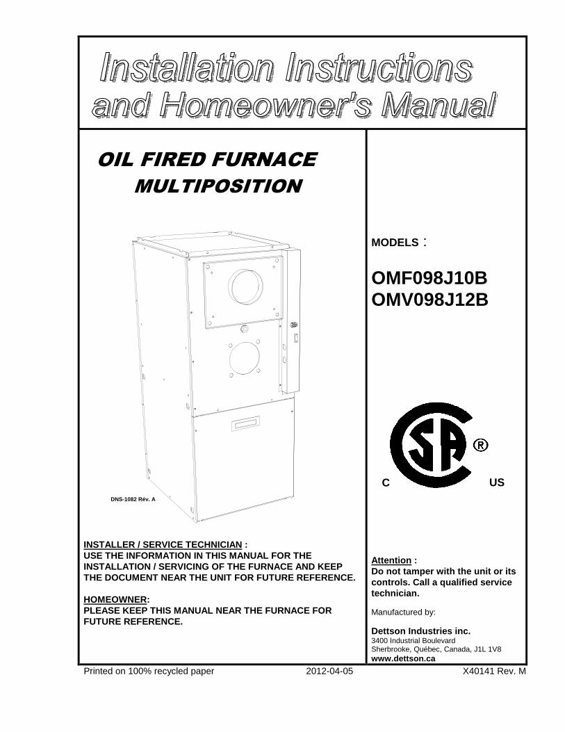
OIL FIRED FURNACE
MULTIPOSITION INSTALLER / SERVICE TECHNICIAN : USE THE INFORMATION IN THIS MANUAL FOR THE INSTALLATION / SERVICING OF THE FURNACE AND KEEP THE DOCUMENT NEAR THE UNIT FOR FUTURE REFERENCE. HOMEOWNER: PLEASE KEEP THIS MANUAL NEAR THE FURNACE FOR FUTURE REFERENCE.
MODELS : OMF098J10B OMV098J12B
Attention : Do not tamper with the unit or its controls. Call a qualified service technician. Manufactured by: Dettson Industries inc. 3400 Industrial Boulevard Sherbrooke, Québec, Canada, J1L 1V8 www.dettson.ca
US C DNS-1082 Rév. A
2
TABLE OF CONTENTS
1. SAFETY REGULATIONS........................................... 3 1.1 SAFETY LABELING AND WARNING SIGNS ............................3 1.2 IMPORTANT INFORMATION......................................................3 1.3 DETECTION SYSTEMS ................................................................3 1.4 DANGER OF FREEZING...............................................................3
2. INSTALLATION.............................................................. 4 2.1 POSITIONING THE FURNACE ................................................4
2.1.1 Installation in an enclosure................................................4 2.2 CONFIGURATIONS ..................................................................4
2.2.1 Upflow Installation ............................................................4 2.2.2 Downflow Installation .......................................................5
2.3 ELECTRICAL SYSTEM ............................................................5 2.4 INSTALLATION OF THE THERMOSTAT...............................5 2.5 INSTALLATION OF THE BURNER.........................................6
2.5.1 Nozzles ..............................................................................6 2.5.2 Air and Turbulator Settings ...............................................6 2.5.3 Post purge delay adjustment ..............................................6
2.6 VENTING ...................................................................................6 2.6.1 Masonry chimney..............................................................7 2.6.2 Factory Built Chimneys.....................................................7 2.6.3 Draft Regulator..................................................................7
2.7 BLOCKED VENT SHUT-OFF DEVICE (BVSO) FOR CHIMNEY VENTING................................................................7 2.8 COMBUSTION AIR SUPPLY AND VENT...............................7
2.8.1 Contaminated Combustion Air..........................................7 2.8.2 Burner with Outdoor Combustion Air Kit .........................8
2.9 OIL TANK ..................................................................................8 2.10 DUCTING...................................................................................8 2.11 SUPPLY AIR ADJUST. (4 SPEED MOTORS)..........................8 2.12 SUPPLY AIR ADJUST.(ECM VAR.SP. MOTORS)..................9 2.13 INSTALLATION OF ACCESSORIES .......................................9
2.13.1 Humidifier (HUM) ............................................................9 2.13.2 Electronic Air Cleaner (EAC)............................................9 2.13.3 Air Conditioner (or Heat Pump)......................................10
3 OPERATION .............................................................. 10 3.1 START-UP................................................................................10 3.2 OPERATING SEQUENCE OIL HEATING MODE.................10 3.3 CHECKS AND ADJUSTMENTS.............................................10
3.3.1 Purging the oil line ..........................................................10 3.3.2 Pressure adjustment.........................................................10 3.3.3 Combustion Check ..........................................................11 3.3.4 Draft Regulator adjustment .............................................11 3.3.5 Overfire pressure test.......................................................11 3.3.6 Vent Temperature Test ....................................................11 3.3.7 Supply Air Temperature Rise Test ..................................11 3.3.8 Limit Control Check...................................... 11 3.3.9 Restart after Burner Failure........................... 11
4 MAINTENANCE........................................................ 12 4.1 CLEANING THE HEAT EXCHANGER..................................12 4.2 CLEANING THE BLOCKED VENT SHUT-OFF DEVICE (BVSO) .....................................................................................12 4.3 CLEANING OF THE BURNER HEAD....................................12 4.4 CHANGING THE NOZZLE .....................................................12 4.5 CHANGING THE OIL FILTER................................................12 4.6 CHANGING THE AIR FILTER................................................12
5 FURNACE INFORMATION .................................... 13
TABLES
Table 1: Blower speed adjustments (4-speed motors) ............ 8
Table 2: Supply air adjustments, ECM variable speed
motors, heating mode...................................................... 9
Table 3: Supply air adjustments, ECM variable speed
motors, air conditioning mode ........................................ 9
Table 4: CFM adjustments, all modes..................................... 9
Table 5: Delay adjustments - heating mode ............................ 9
Table 6: Technical specifications.......................................... 14
Table 7: Airflow data, models with 1/2 HP ECM motors..... 15
Table 8: Airflow data, models with 1/3 HP PSC motors ...... 16
Table 9: Minimum clearances from combustible materials .. 16
Table 10: Parts list with 4-speed motor (PSC)...................... 21
Table 11: Parts list with variable speed motor (ECM).......... 23
FIGURES
Figure 1: Location and dimensions of ventilation air
openings in a closet door................................................. 4
Figure 2: Upflow installation .................................................. 4
Figure 3: Downflow installation ............................................. 5
Figure 4: Horizontal installation ............................................. 5
Figure 5: Thermostat wiring, heating and air conditioning
with 4-speed motor ......................................................... 5
Figure 6: Thermostat wiring heating and air conditioning
with ECM variable speed motor ..................................... 6
Figure 7: Thermostat wiring, heating and air cond. heat
pump with ECM v. speed motor ..................................... 6
Figure 8: Blower start/stop delays........................................... 9
Figure 9: Furnace dimensions ............................................... 17
Figure 10: Wiring diagram, 4-speed motor (PSC) ................ 18
Figure 11: Wiring diagram, variable speed motor (ECM) .... 19
Figure 12: Parts list with 4-speed motor (PSC)..................... 20
Figure 13: Parts list with variable speed motor (ECM)......... 22
3
1. SAFETY REGULATIONS
1.1 SAFETY LABELING AND WARNING SIGNS
The words DANGER, WARNING AND CAUTION are used to identify the levels of seriousness of certain hazards. It is important that you understand their meaning. You will notice these words in the manual as follows:
DANGER
Immediate hazards that WILL result in death, serious bodily injury and/or property damage.
WARNING
Hazards or unsafe practices that CAN result in deat h, bodily injury and/or property damage.
CAUTION Hazards or unsafe practices that CAN result in bodily injury and/or property damage.
1.2 IMPORTANT INFORMATION
WARNING
Non-observance of the safety regulations outlined i n this manual will potentially lead to consequences result ing in death, serious bodily injury and/or property damage .
a) It is the homeowner’s responsibility to engage a qualified technician for the installation and subsequent servicing of this furnace;
b) Do not use this furnace if any part of it was un der water. Call a qualified service technician immediat ely to assess the damage and to replace all critical pa rts that were in contact with water;
c) Do not store gasoline or any other flammable substances, such as paper, carton, etc. near the furnace;
d) This furnace is designed for use with #1 or #2 h eating oil only. The use of gasoline, motor oil or any oth er oil containing gasoline is prohibited;
e) Never block or otherwise obstruct the filter and /or return air openings;
f) Ask the technician installing your furnace to sh ow and explain to you the following items:
i) The main disconnect switch; ii) The shut-off valve on the oil tank;
iii) The oil filter and how to change it (once a ye ar); iv) The air filter and how to change it (check mont hly
and clean or replace if necessary.)
g) Before calling for service, be sure to have the information page in section 5 of your manual close by in order to be able to provide the contractor with the required information, such as the model and serial numbers of the furnace.
WARNING
Installations and repairs performed by unqualified persons can result in hazards to them and to others . Installations must conform to local codes or, in th e absence of same, to codes of the country having jurisdiction.
The information contained in this manual is intende d for use by a qualified technician, familiar with sa fety procedures and who is equipped with the proper tool s and test instruments.
Failure to carefully read and follow all instructio ns in this manual can result in death, bodily injury and/ or property damage.
1.3 DETECTION SYSTEMS
It is recommended that carbon monoxide detectors be installed wherever oil or gas fired heaters are used. Carbon monoxide can cause bodily harm or death. For this reason, agency approved carbon monoxide detectors should be installed in your residence and properly maintained to warn of dangerously high carbon monoxide levels.
There are several sources of possible smoke and flames in a residence. Smoke and flames can cause bodily harm or death. For this reason, agency approved smoke detectors should be installed in your residence and properly maintained, to warn early on, of a potentially dangerous fire. Also, the house should be equipped with approved and properly maintained fire extinguishers.
Your unit is equipped with safety devices that can prevent it from functioning when anomalies are detected such as a blocked venting system.
1.4 DANGER OF FREEZING
CAUTION If your furnace is shut down during the cold weather season, water pipes may freeze, burst and cause serious water damage. Turn off the water supply and bleed the pipes.
If the heater is left unattended during the cold weather season, take the following precautions:
a. Close the main water valve in the house and purge the pipes if possible. Open all the faucets in the house;
b. Ask someone to frequently check the house during the cold weather season to make sure that there is sufficient heat to prevent the pipes from freezing. Tell this person to call an emergency number if required.
4
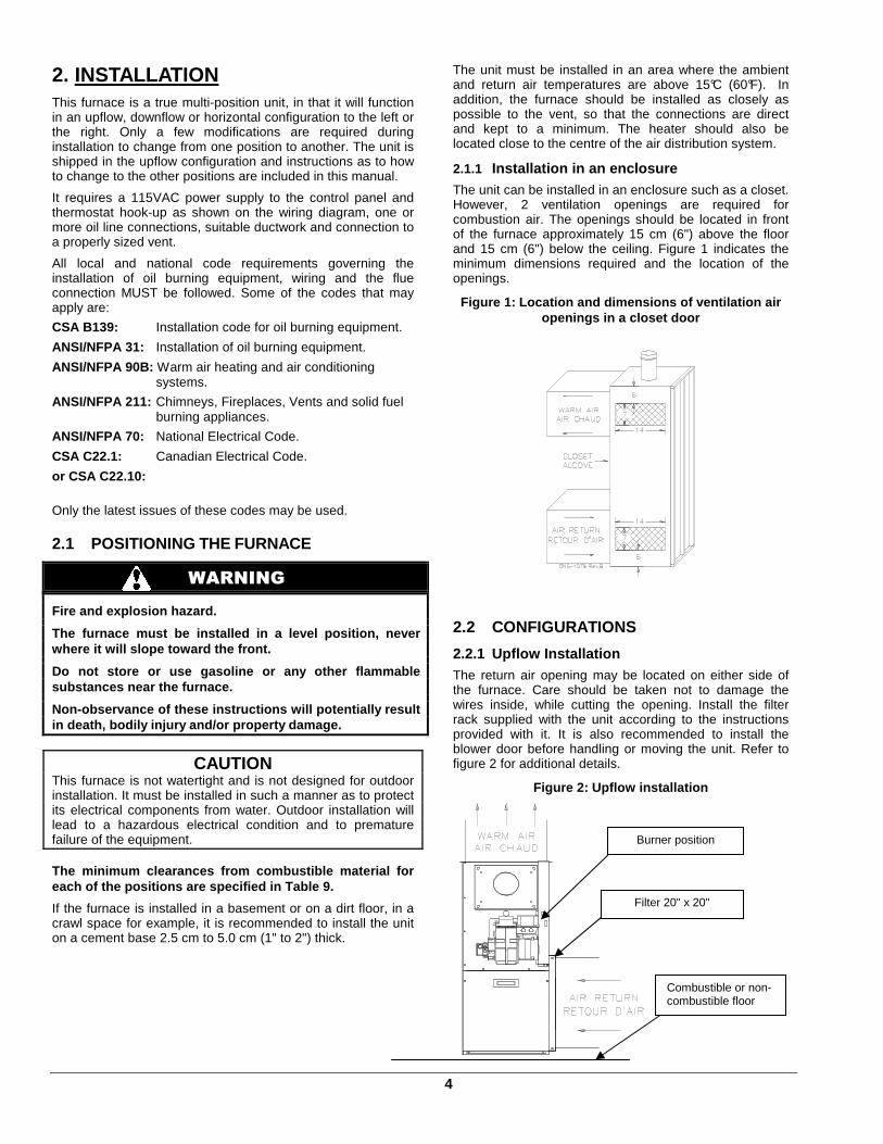
2. INSTALLATION This furnace is a true multi-position unit, in that it will function in an upflow, downflow or horizontal configuration to the left or the right. Only a few modifications are required during installation to change from one position to another. The unit is shipped in the upflow configuration and instructions as to how to change to the other positions are included in this manual.
It requires a 115VAC power supply to the control panel and thermostat hook-up as shown on the wiring diagram, one or more oil line connections, suitable ductwork and connection to a properly sized vent.
All local and national code requirements governing the installation of oil burning equipment, wiring and the flue connection MUST be followed. Some of the codes that may apply are:
CSA B139: Installation code for oil burning equipment.
ANSI/NFPA 31: Installation of oil burning equipment.
ANSI/NFPA 90B: Warm air heating and air conditioning systems.
ANSI/NFPA 211: Chimneys, Fireplaces, Vents and solid fuel burning appliances.
ANSI/NFPA 70: National Electrical Code.
CSA C22.1: Canadian Electrical Code.
or CSA C22.10:
Only the latest issues of these codes may be used.
2.1 POSITIONING THE FURNACE
WARNING
Fire and explosion hazard.
The furnace must be installed in a level position, never where it will slope toward the front.
Do not store or use gasoline or any other flammable substances near the furnace.
Non-observance of these instructions will potential ly result in death, bodily injury and/or property damage.
CAUTION This furnace is not watertight and is not designed for outdoor installation. It must be installed in such a manner as to protect its electrical components from water. Outdoor installation will lead to a hazardous electrical condition and to premature failure of the equipment. The minimum clearances from combustible material fo r each of the positions are specified in Table 9.
If the furnace is installed in a basement or on a dirt floor, in a crawl space for example, it is recommended to install the unit on a cement base 2.5 cm to 5.0 cm (1" to 2") thick.
The unit must be installed in an area where the ambient and return air temperatures are above 15°C (60°F). In addition, the furnace should be installed as closely as possible to the vent, so that the connections are direct and kept to a minimum. The heater should also be located close to the centre of the air distribution system.
2.1.1 Installation in an enclosure The unit can be installed in an enclosure such as a closet. However, 2 ventilation openings are required for combustion air. The openings should be located in front of the furnace approximately 15 cm (6") above the floor and 15 cm (6") below the ceiling. Figure 1 indicates the minimum dimensions required and the location of the openings.
Figure 1: Location and dimensions of ventilation ai r openings in a closet door
2.2 CONFIGURATIONS
2.2.1 Upflow Installation The return air opening may be located on either side of the furnace. Care should be taken not to damage the wires inside, while cutting the opening. Install the filter rack supplied with the unit according to the instructions provided with it. It is also recommended to install the blower door before handling or moving the unit. Refer to figure 2 for additional details.
Figure 2: Upflow installation
Filter 20" x 20"
Burner position
Combustible or non-combustible floor

5
2.2.2 Downflow Installation When the furnace is installed in the downflow position on a combustible floor, the clearances from combustibles must be adhered to. The downflow base DFB-102 or KLASB0801DET can be used to ensure these clearances. Refer to Figure 3 and the installation instructions provided with the base.
In cases where the return air enters through the floor, the floor return base FRB-101 or KLARB0101DET must be used.
The burner must always be installed in the same manner, regardless of the discharge position of the furnace. Refer to Figure 3 for additional details. The protection plate (B03789) must be installed on the plastic cover of the Beckett NX burner to protect it from vent.
Figure 3: Downflow installation
2.2.3 Horizontal Installation
When the furnace is installed in the horizontal position, either suspended or on a combustible floor with a choice of right or left discharge, the clearances from combustible material must be adhered to. If the unit is installed on a combustible floor, the horizontal floor base HFB-101 or KLASB0701DET can be used to ensure these clearances. Refer to the instructions supplied with the base.
In cases where the return air enters through the floor, the floor return base FRB-101 or KLARB0101DET can be installed as per the supplied instructions.
The burner must always be installed in the same manner, regardless of the discharge position of the furnace. Refer to Figure 4 for additional details.
Figure 4: Horizontal installation
2.3 ELECTRICAL SYSTEM
CAUTION The exterior of the unit must have an uninterrupted ground to minimize the risk of bodily harm, if ever an electrical problem develops. A green ground screw is supplied with the control box for that purpose. The appliance must be installed in accordance with the current ANSI/NFPA 70 National Electrical Code, CSA C22.1 Canadian Electrical Code Part 1 and/or local codes.
The control system depends on the correct polarity of the power supply. Connect “HOT” wire (H) and “NEUTRAL” wire (N) as shown in figures 10 and 11.
A separate line voltage supply should be used, with fused disconnect switch or circuit breaker, between the main power panel and the unit.
Only copper wire may be used for the 115V circuit on this unit. If wires need to be changed, the replacements must have the same temperature resistance as the originals.
2.4 INSTALLATION OF THE THERMOSTAT
A thermostat must be installed to control the temperature of the area to be heated. Follow the instructions supplied with the thermostat. Also refer to the wiring diagrams provided with the heating/air conditioning unit. The connections must be made as indicated on the following diagrams and the wiring diagrams, figures 10 and 11.
Figure 5: Thermostat wiring, heating and air conditioning with 4-speed motor
Filter rack 20" x 20"
Floor Return Base
Downflow base is required for combustible floor
Floor Return Burner
Horizontal floor base required for combustible floor
Filter rack 20" x 20"
Burner position
6
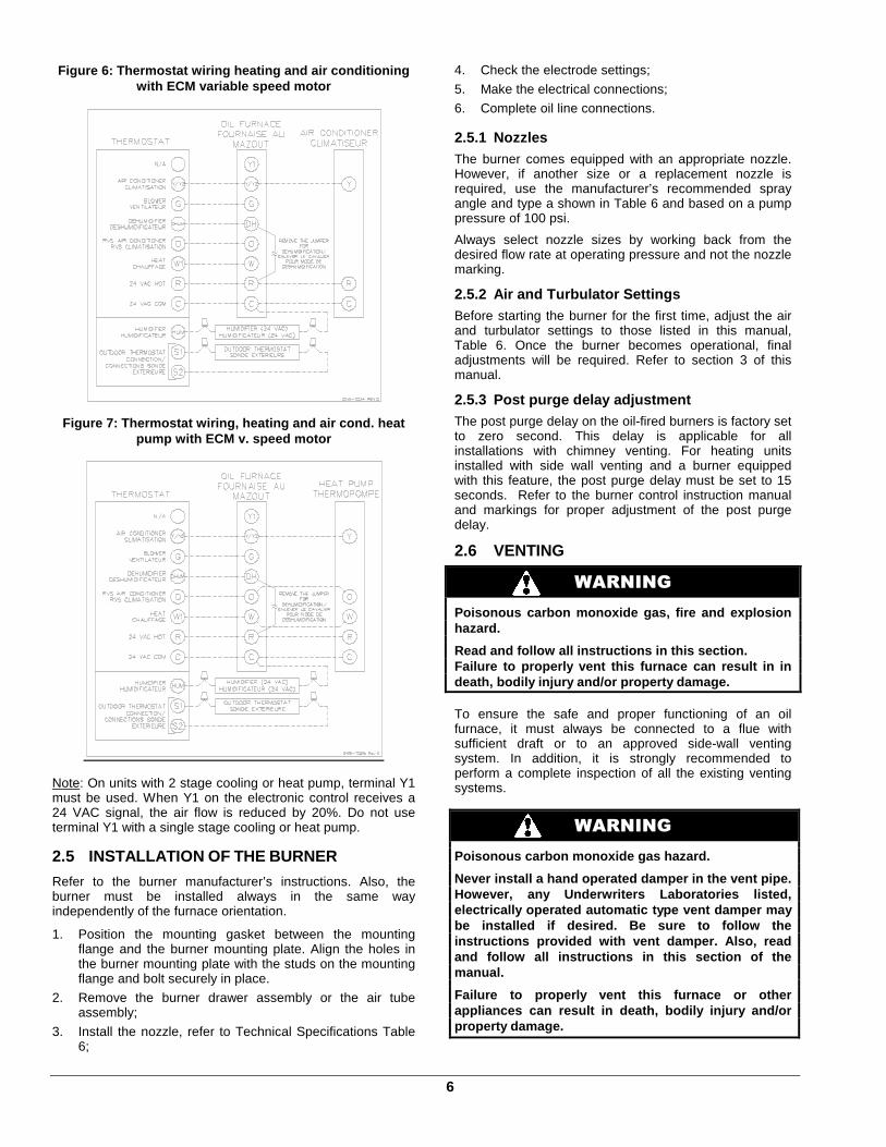
Figure 6: Thermostat wiring heating and air conditi oning with ECM variable speed motor
Figure 7: Thermostat wiring, heating and air cond. heat pump with ECM v. speed motor
Note: On units with 2 stage cooling or heat pump, terminal Y1 must be used. When Y1 on the electronic control receives a 24 VAC signal, the air flow is reduced by 20%. Do not use terminal Y1 with a single stage cooling or heat pump.
2.5 INSTALLATION OF THE BURNER
Refer to the burner manufacturer’s instructions. Also, the burner must be installed always in the same way independently of the furnace orientation.
1. Position the mounting gasket between the mounting flange and the burner mounting plate. Align the holes in the burner mounting plate with the studs on the mounting flange and bolt securely in place.
2. Remove the burner drawer assembly or the air tube assembly;
3. Install the nozzle, refer to Technical Specifications Table 6;
4. Check the electrode settings;
5. Make the electrical connections;
6. Complete oil line connections.
2.5.1 Nozzles The burner comes equipped with an appropriate nozzle. However, if another size or a replacement nozzle is required, use the manufacturer’s recommended spray angle and type a shown in Table 6 and based on a pump pressure of 100 psi.
Always select nozzle sizes by working back from the desired flow rate at operating pressure and not the nozzle marking.
2.5.2 Air and Turbulator Settings Before starting the burner for the first time, adjust the air and turbulator settings to those listed in this manual, Table 6. Once the burner becomes operational, final adjustments will be required. Refer to section 3 of this manual.
2.5.3 Post purge delay adjustment The post purge delay on the oil-fired burners is factory set to zero second. This delay is applicable for all installations with chimney venting. For heating units installed with side wall venting and a burner equipped with this feature, the post purge delay must be set to 15 seconds. Refer to the burner control instruction manual and markings for proper adjustment of the post purge delay.
2.6 VENTING
WARNING
Poisonous carbon monoxide gas, fire and explosion hazard.
Read and follow all instructions in this section. Failure to properly vent this furnace can result in in death, bodily injury and/or property damage. To ensure the safe and proper functioning of an oil furnace, it must always be connected to a flue with sufficient draft or to an approved side-wall venting system. In addition, it is strongly recommended to perform a complete inspection of all the existing venting systems.
WARNING
Poisonous carbon monoxide gas hazard.
Never install a hand operated damper in the vent pi pe. However, any Underwriters Laboratories listed, electrically operated automatic type vent damper ma y be installed if desired. Be sure to follow the instructions provided with vent damper. Also, read and follow all instructions in this section of the manual.
Failure to properly vent this furnace or other appliances can result in death, bodily injury and/o r property damage.
7
2.6.1 Masonry chimney
This furnace can be vented into an existing masonry chimney. However, the unit must not be vented into a chimney into which a solid fuel burning furnace is already being vented.
Before venting this furnace into a chimney, its condition must be checked and repairs made, if necessary. Also, the chimney lining and dimensions must conform to local and national codes.
2.6.2 Factory Built Chimneys
Oil fired furnaces are approved for use with “L” type vents. The unit may also be used with an approved chimney of proper dimensions and temperature ratings as specified in the installation code. Refer to chimney manufacturer’s instructions for proper installation.
2.6.3 Draft Regulator It is recommended that a draft regulator be installed in cases where the draft is either high or variable due to external conditions. Follow the instructions provided with the regulator.
2.6.4 Side-wall Venting
The heating unit is approved for side-wall venting. This system is comprised of a model VTK-098/KLAVT0101DET side-wall venter and a 4” insulated vent pipe, model IFV098-10/KLAFV0101DET, IFV098-20/KLAFV0201DET. Refer to the installation instructions provided with the venting system.
2.7 BLOCKED VENT SHUT-OFF DEVICE (BVSO) FOR CHIMNEY VENTING
CAUTION It is imperative that this device be installed by a qualified service technician.
A positive pressure venting system (Sealed Combustion System or Direct Vent) MUST NOT use the BVSO. Follow the instructions supplied with the venting system. This device is designed to detect the insufficient evacuation of combustion gases in the event of a vent blockage. In such a case the thermal switch will shut down the oil burner. The device will then need to be re-armed MANUALLY. Refer to the detailed instructions and wiring diagrams supplied with the BVSO for the installation and wiring procedures. The length of wires supplied with the unit is such that the safety device must be installed between the flue outlet of the appliance and the draft regulator, as indicated in the instructions. It is also essential that the BVSO be maintained annually. For more details refer to the instructions supplied with the device itself, as well as Section 3. of this Manual. 2.7.1 BVSO Performance Test
The purpose of the following test is to check that the electrical outlet on the furnace, designated to the BVSO, is functional.
1. Start up the burner; 2. Remove the three-pole plug from the BVSO outlet on
the furnace; 3. The burner must shut-off immediately, while the
blower continues to run to the end of the cool-down cycle.
If the test is not in line with the above, call a QUALIFIED SERVICE TECHNICIAN.
2.8 COMBUSTION AIR SUPPLY AND VENTILATION
WARNING
Poisonous carbon monoxide gas hazard.
Comply with NFPA 31 (U.S.) and CSA B139 (Canada) standards for the installation of Oil Burning Equipment and applicable provisions of local buildi ng codes to provide combustion and ventilation air.
Failure to provide adequate combustion and ventilation air can result in death, bodily injury and/or property damage.
Oil furnaces must have an adequate supply of combustion air. It is common practice to assume that older homes have sufficient infiltration to accommodate the combustion air requirement for the furnace. However, home improvements such as new windows, doors, and weather stripping have drastically reduced the volume of air infiltration into the home.
Refer to oil furnace installation codes relative to combustion and ventilation air requirements. Consult Section 2.2 in this manual, specifically for units installed in an enclosed space.
Home air exhausters are common. Bathroom and kitchen fans, power vented clothes dryers and water heaters all tend to create a negative pressure condition in the home. Should this occur the chimney becomes less and less effective and can easily downdraft. In certain cases, mechanically supplied air, by way of a blower, interlocked with the unit, is necessary. It is the installer’s responsibility to check that.
2.8.1 Contaminated Combustion Air Installations in certain areas or types of structures will increase the exposure to chemicals or halogens that may harm the furnace. These conditions will require that only outside air be used for combustion.
The following areas or types of structures may contain or be exposed to certain substances, potentially requiring outside air for combustion:
a. Commercial buildings; b. Buildings with indoor pools; c. Furnaces installed near chemical storage areas.
Exposure to the following substances: a. Permanent wave chemicals for hair; b. Chlorinated waxes and cleaners; c. Chlorine based swimming pool chemicals; d. Water softening chemicals; e. De-icing salts or chemicals; f. Carbon tetrachloride;
8
g. Halogen type refrigerants; h. Cleaning solvents (such as perchloroethylene); i. Printing inks, paint removers, varnishes, etc. ; j. Hydrochloric acid; k. Solvent based glue; l. Antistatic fabric softeners for clothes dryers; m. Acid based masonry cleaning materials.
2.8.2 Burner with Outdoor Combustion Air Kit
Certain burners are designed to function with combustion air taken directly from the outside. Follow the instructions provided with the burner, the fresh-air supply kit or the side-wall venting kit.
2.9 OIL TANK
WARNING
Fire and explosion hazard.
Use only approved heating type oil in this furnace. DO NOT USE waste oil, used motor oil, gasoline or kerosene.
Use of these will result in death, bodily injury an d/or property damage.
CAUTION
When a 0.75 USGPH or smaller nozzle is used, a 10 micron or finer filter, must be installed on the oil supply line to the furnace inside the building where the unit is located.
This is a requirement in order for the heat exchanger warranty to remain in force. Check your local codes for the installation of the oil tank and accessories.
At the beginning of each heating season or once a year, check the complete oil distribution system for leaks.
Ensure that the tank is full of clean oil. Use No.1 or No.2 Heating Oil (ASTM D396 U.S.) or in Canada, use No.1 or No.2 Furnace Oil.
A manual shut-off valve and an oil filter shall be installed in sequence from tank to burner. Be sure that the oil line is clean before connecting to the burner. The oil line should be protected to eliminate any possible damage. Installations where the oil tank is below the burner level must employ a two-pipe fuel supply system with an appropriate fuel pump. A rise of 2.4 m (8') and more requires a two stage pump and a rise greater than 4.9 m (16') an auxiliary pump. Follow the pump instructions to determine the size of pipe needed in relation to the rise or to the horizontal distance.
2.10 DUCTING
WARNING
Poisonous carbon monoxide gas hazard.
DO NOT draw return air from inside a closet or util ity room. Return air MUST be sealed to the furnace casing.
Failure to properly seal ducts can result in death, bodily injury and/or property damage. The ducting must be designed and installed according to approved methods, local and national codes as well as good trade practices.
When ducting supplies air to a space other than where the furnace is located, the return air must be sealed and also be directed to the space other than where the furnace is located.
2.10.1 Air filter
A properly sized air filter must be installed on the return air side of the unit. Refer to the Technical Specifications, table 6, for the correct dimensions. Also refer to Section 2.2 and the instructions supplied with the filter.
2.11 SUPPLY AIR ADJUSTMENTS (4 SPEED MOTORS)
On units equipped with 4-speed blower motors, the supply air must be adjusted based on heating/air conditioning output and the static pressure of the duct system. For the desired air flow refer to the following table as well as the air flow tables based on static pressure in the Technical Specifications, table 6, of this manual.
Table 1: Blower speed adjustments (4-speed motors)
FURNACE APPLICATION
HEATING OR A/C OUTPUT
RECOMMENDED BLOWER SPEED
0.50 USGPH MED-LOW 0.60 USGPH MED-HIGH HEATING 0.70 USGPH HIGH
2.0 TONS MED-LOW 2.5 TONS MED-HIGH A/C 3.0 TONS HIGH
To effect the adjustment, the RED (for heating) and BLUE (for cooling and heat pump) wires can be changed on the motor. Also, refer to the position of the wires on the electronic board of the unit and consult the wiring diagrams. If the heating and air conditioning speeds are the same, the RED wire must be moved to “UNUSED LEADS” on the electronic board and the jumper provided with the BLUE wire must be used between the “HEAT” and “COOL” terminals.
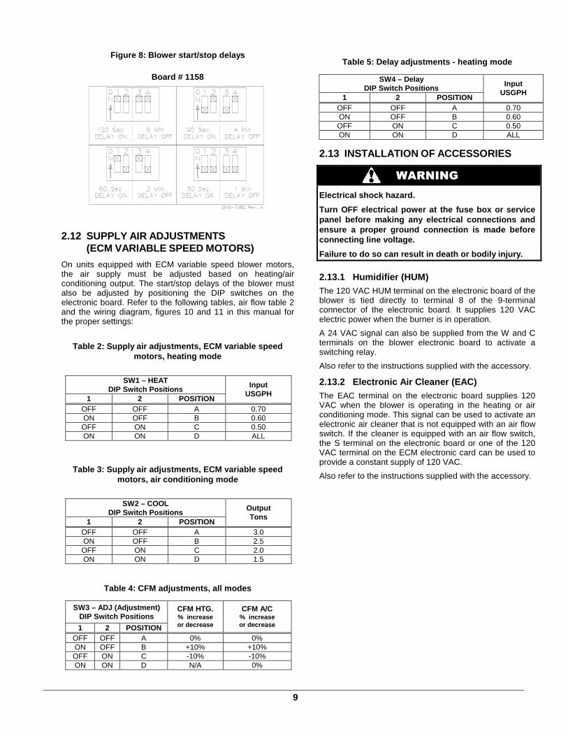
The blower start/stop delays can be adjusted by positioning the DIP switches on the electronic board as shown in the following figures. The recommended blower ON delay is 60 seconds and the blower OFF delay is 2 minutes.
9
Figure 8: Blower start/stop delays
Board # 1158
2.12 SUPPLY AIR ADJUSTMENTS
(ECM VARIABLE SPEED MOTORS)
On units equipped with ECM variable speed blower motors, the air supply must be adjusted based on heating/air conditioning output. The start/stop delays of the blower must also be adjusted by positioning the DIP switches on the electronic board. Refer to the following tables, air flow table 2 and the wiring diagram, figures 10 and 11 in this manual for the proper settings:
Table 2: Supply air adjustments, ECM variable speed motors, heating mode
SW1 – HEAT DIP Switch Positions
1 2 POSITION
Input USGPH
OFF OFF A 0.70 ON OFF B 0.60 OFF ON C 0.50 ON ON D ALL
Table 3: Supply air adjustments, ECM variable speed motors, air conditioning mode
SW2 – COOL DIP Switch Positions
1 2 POSITION
Output Tons
OFF OFF A 3.0 ON OFF B 2.5 OFF ON C 2.0 ON ON D 1.5
Table 4: CFM adjustments, all modes
SW3 – ADJ (Adjustment) DIP Switch Positions
1 2 POSITION
CFM HTG. % increase or decrease
CFM A/C % increase or decrease
OFF OFF A 0% 0% ON OFF B +10% +10% OFF ON C -10% -10% ON ON D N/A 0%
Table 5: Delay adjustments - heating mode
SW4 – Delay DIP Switch Positions
1 2 POSITION
Input USGPH
OFF OFF A 0.70 ON OFF B 0.60 OFF ON C 0.50 ON ON D ALL
2.13 INSTALLATION OF ACCESSORIES
WARNING
Electrical shock hazard.
Turn OFF electrical power at the fuse box or servic e panel before making any electrical connections and ensure a proper ground connection is made before connecting line voltage.
Failure to do so can result in death or bodily inju ry.
2.13.1 Humidifier (HUM) The 120 VAC HUM terminal on the electronic board of the blower is tied directly to terminal 8 of the 9-terminal connector of the electronic board. It supplies 120 VAC electric power when the burner is in operation.
A 24 VAC signal can also be supplied from the W and C terminals on the blower electronic board to activate a switching relay.
Also refer to the instructions supplied with the accessory.
2.13.2 Electronic Air Cleaner (EAC) The EAC terminal on the electronic board supplies 120 VAC when the blower is operating in the heating or air conditioning mode. This signal can be used to activate an electronic air cleaner that is not equipped with an air flow switch. If the cleaner is equipped with an air flow switch, the S terminal on the electronic board or one of the 120 VAC terminal on the ECM electronic card can be used to provide a constant supply of 120 VAC.
Also refer to the instructions supplied with the accessory.
10
2.13.3 Air Conditioner (or Heat Pump) An air conditioning coil may be installed on the supply air side ONLY.
WARNING
Poisonous carbon monoxide gas hazard.
Install the evaporator coil on the supply side of t he furnace ducting ONLY.
An evaporator coil installed on the return air side of the ducting can cause condensation to form inside the h eat exchanger, resulting in heat exchanger failure. Thi s in turn, can result in death, bodily injury and/or pro perty damage. A clearance of 15 cm (6") is required between the bottom of the coil drain pan and the top of the heat exchanger. If a heat pump is installed, a “dual-energy” thermostat, or other control is recommended, in order to prevent the simultaneous operation of the furnace and the heat pump. It also prevents a direct transition from heating by way of the heat pump to heating with oil. Refer to the thermostat instructions or those of another control used for the proper wiring.
3 OPERATION
3.1 START-UP
Before starting up the unit, be sure to check that the following items are in compliance:
1. The electrical installation, the oil supply system, the venting system, combustion air supply and ventilation;
2. The blower access door is in place and the blower rail locking screws are well tightened;
3. The Blocked Vent Shut-Off (BVSO) is installed according to instructions (for chimney venting);
4. The oil supply valve is open;
5. The burner ‘’Reset’’ button is well pushed in or re-armed;
6. The preliminary air adjustments on the burner comply with the technical specifications in this manual;
7. The blower speed adjustments for heating and air conditioning are appropriate and according to the specifications in this manual;
8. The blower start/stop delays are satisfactory;
9. The thermostat of the room is in the heating mode and is set higher than the ambient temperature.
To start the unit, turn the main electrical switch on.
3.2 OPERATING SEQUENCE OIL HEATING MODE
1. The W-R contact closes; 2. The burner motor starts up to pre-purge the
combustion chamber for a period of 10 to 15 seconds. During that time a spark is established on the electrodes;
3. The solenoid valve opens and a flame is established. Shortly after, the electrodes cease to spark;
4. Then the blower runs up to full speed. The delay depends on the adjustments that were made on the electronic board, which controls the blower motor. Refer to Sections 2.11 and 2.12, as well as the CFM table 7 for more details.
5. When the call for heat is satisfied, the solenoid valve closes, the flame goes out and the burner motor stops (after post purge delay, if applicable).
6. The blower stops shortly after the burner. The delay depends on the adjustments that were made on the electronic board that controls the blower. Refer to Sections 2.11 and 2.12, as well as the CFM table 7 for more details.
Note: A detailed operating sequence of the oil burner is outlined in the instructions provided with the burner.
3.3 CHECKS AND ADJUSTMENTS
3.3.1 Purging the oil line
Open the bleed port screw and start the burner. Allow the oil to drain into a container for at least 10 seconds. The oil should flow absolutely free of white streaks or air bubbles to indicate that no air is being drawn into the suction side of the oil piping and pump. Slowly close and tighten the bleed screw. Once closed, the flame will light up.
3.3.2 Pressure adjustment
The oil pressure must be adjusted according to the Technical Specifications of this manual. An adjustment screw and a connection for a pressure gauge are located on the oil pump for that purpose. Also refer to the burner instruction manual.
11
CAUTION Low flue gas temperatures increase the risk of condensation. Adjust the total temperature at or higher then 204°C (400°F) in order for the heat exchanger warranty to remain in force.
3.3.3 Combustion Check
IMPORTANT The heat exchanger metal surfaces may have oil and the baffle insulation also contains binders. These products will burn or evaporate when the unit operates for the first time. Because of that, the smoke reading may be skewed during the first minutes of operation. Therefore, the unit must operate during at least 60 minutes before taking any readings to adjust the combustion quality. Let the unit cool down before making any adjustments.
IMPORTANT The combustion check verification MUST be performed after the nozzle replacement or the burner cleaning. After these manipulations, the combustion parameters are necessarily modified. Refer also to the burner instruction manual.
1. Pierce a test hole in the flue pipe, approximately 18 inches from the furnace breech. Insert the smoke test probe into the hole. For installation using a sidewall venting, use the orifice provided on the breech plate;
2. From a cold start, let the unit operate for about 5 minutes;
3. Set the burner air setting until you have between 0 and 1 on the Bacharach Scale (or a ‘’trace’’);
4. Take a CO2 sample at the same test location where the #1 smoke reading was taken and make note of it. Example: 13.8% of CO2 or 2.5% of O2;
5. Adjust the burner air setting to obtain a CO2 reading 1.5% lower (or a O2 reading 2.0% higher) than the reading associated with the ‘’trace’’ of smoke. Example: 12.3% of CO2 or 4.5% of O2;
6. This method of adjusting the burner will result in clean combustion (Bacharach smoke scale between 0 and a ‘’trace’’) and ensure the proper functioning of the system. The optimum CO2 level is around 12% to 13% (or 3.5% to 5.0% of O2).
3.3.4 Draft Regulator adjustment On chimney installations only, a barometric draft regulator (supplied with the furnace) must be installed, in order to ensure proper draft through the furnace. The barometric damper must be mounted with the hinge pins in a horizontal position and the face of the damper vertical for proper functioning (see instructions included with the damper.) After the furnace has been firing for at least five minutes, the draft regulator should be set to between -0.025" and -0.060" W.C.
3.3.5 Overfire pressure test The overfire draft that is taken through the observation port, located above the burner, is a measurement necessary to determine if there is a blockage in the heat exchanger or the flue pipe. Refer to the Technical Specifications in this manual for overfire pressure values. A high pressure condition may be caused by excessive combustion air, due to the air band being too wide open, or a lack of flue draft (chimney effect) or some other blockage, such as soot in the secondary section of the heat exchanger or the use of an oversize nozzle input or high pressure pump.
3.3.6 Vent Temperature Test 1. After having adjusted the burner combustion, insert a
thermometer into the test hole in the breech pipe;
2. The total vent temperature should be between 204 and 302°C (400 and 575°F). If not, check for improper air temperature rise, pump pressure, nozzle size or a badly sooted heat exchanger.
3.3.7 Supply Air Temperature Rise Test 1. Operate the burner for at least 10 minutes;
2. Measure the air temperature in the return air plenum;
3. Measuring the air temperature in the largest trunk coming off the supply air plenum, just outside the range of radiant heat from the heat exchanger. 0.3 m (12") from the plenum of the main take-off is usually sufficient;
4. The temperature rise is calculated by subtracting the return air temperature from the supply air temperature;
5. If the temperature rise is lower or exceeds the temperature specified in Table 6, change to the next lower or higher blower speed tap, until the temperature rise falls to the target. If the excessive temperature rise cannot be increased or reduced by changing fan speed, investigate for ductwork obstructions, dirty or improper air filter, improper firing caused by improper pump pressure or nozzle sizing.
3.3.8 Limit Control Check After operating the furnace for at least 15 minutes, restrict the return air supply by blocking the filters or the return air register and allow the furnace to shut off on High Limit. The burner will shut off but the blower will continue to run.
Remove the obstruction and the burner should restart after a few minutes. The time required for the restart also depends on the adjustment of the blower “OFF” delay.
3.3.9 Restart after Burner Failure 1. Set the thermostat lower than room temperature;
2. Press the reset button on the burner primary control (relay);
3. Set the thermostat higher than room temperature;
4. If the burner motor does not start or ignition fails, turn off the disconnect switch and CALL A QUALIFIED SERVICE TECHNICIAN.
CAUTION
Do not attempt to start the burner when excess oil has accumulated, when the furnace is full of vapour or when the combustion chamber is hot.
12
4 MAINTENANCE
WARNING
Electrical shock hazard.
Turn OFF power and fuel to the furnace before any disassembly or servicing.
Failure to do so can result in death, bodily injury and/or property damage.
Preventive maintenance is the best way to avoid unnecessary expense and inconvenience. Have your heating system and burner inspected by a qualified service technician at regular intervals.
To maintain the reliability and optimal performance of the furnace, have a complete combustion check done after the annual maintenance call. Do not attempt to repair the furnace or its controls. Call a qualified service technician.
Before calling for repair service check the following points:
1. Check the oil tank gauge and make sure that the valve is open;
2. Check fuses and the circuit breaker;
3. Check if the main disconnect switch is ON ;
4. Set the thermostat above room temperature;
5. If ignition does not occur, turn off the disconnect switch and call a qualified service technician.
When ordering replacement parts, please specify the complete furnace model number and serial number.
4.1 CLEANING THE HEAT EXCHANGER
It is not generally necessary to clean the heat exchanger or flue pipe every year, but it is advisable to have the oil burner service technician check the unit before each heating season to determine whether the cleaning or replacement of parts is necessary.
If a cleaning is necessary, the following steps should be performed: 1. Turn OFF all utilities upstream from the furnace ;
2. Disconnect the flue pipe;
3. Remove the flue collar panel located at the front of the furnace;
4. Remove the heat exchanger baffles;
5. Disconnect the oil line and remove the oil burner;
6. Clean the secondary tubes and the primary cylinder with a stiff brush and a vacuum cleaner;
7. Before re-assembling the unit, the heat exchanger and combustion chamber should be inspected to determine if replacement is required;
8. After the cleaning replace the heat exchanger baffles, flue collar plate and oil burner;
9. Readjust the burner for proper operation.
4.2 CLEANING THE BLOCKED VENT SHUT-OFF DEVICE (BVSO)
For continuous safe operation, the Blocked Vent Shut-off device (BVSO) must be inspected and maintained annually by a qualified service technician.
1. Disconnect power to the appliance;
2. Remove the two screws holding on the BVSO assembly cover;
3. Remove the cover;
4. Remove the two screws holding the control box to the heat transfer tube assembly. Sliding the control box in the appropriate direction will unlock it from the heat transfer tube assembly;
5. Carefully remove any build-up from the thermal switch surface;
CAUTION Do not dent or scratch the surface of the thermal switch. If the thermal switch is damaged it MUST be replaced.
6. Clean and remove any build-up or obstruction inside the heat transfer tube;
7. Re-mount, lock and fasten the control box with the 2 screws removed in step 4;
8. Re-attach the assembly cover with the screws removed in step 2;
9. Re-establish power to the unit.
4.3 CLEANING OF THE BURNER HEAD Once annually, remove the retention head and electrodes from the drawer assembly and remove all foreign matter, if necessary. Also clean the extremity of the burner tube, if necessary.
4.4 CHANGING THE NOZZLE
Change the nozzle once a year with the one specified in Table 6.
4.5 CHANGING THE OIL FILTER
Tank Filter
The tank filter should be changed as required. Follow the manufacturer’s instructions.
Secondary Filter
The 10 micron, or finer, filter cartridge should be changed annually. Follow the manufacturer’s instructions.
4.6 CHANGING THE AIR FILTER Dirty filters have an impact on the efficiency of the furnace and increase fuel consumption. Air filters should be changed at least once a year. Very dusty conditions, the presence of animal hair and the like will require more frequent changing or cleaning.
13
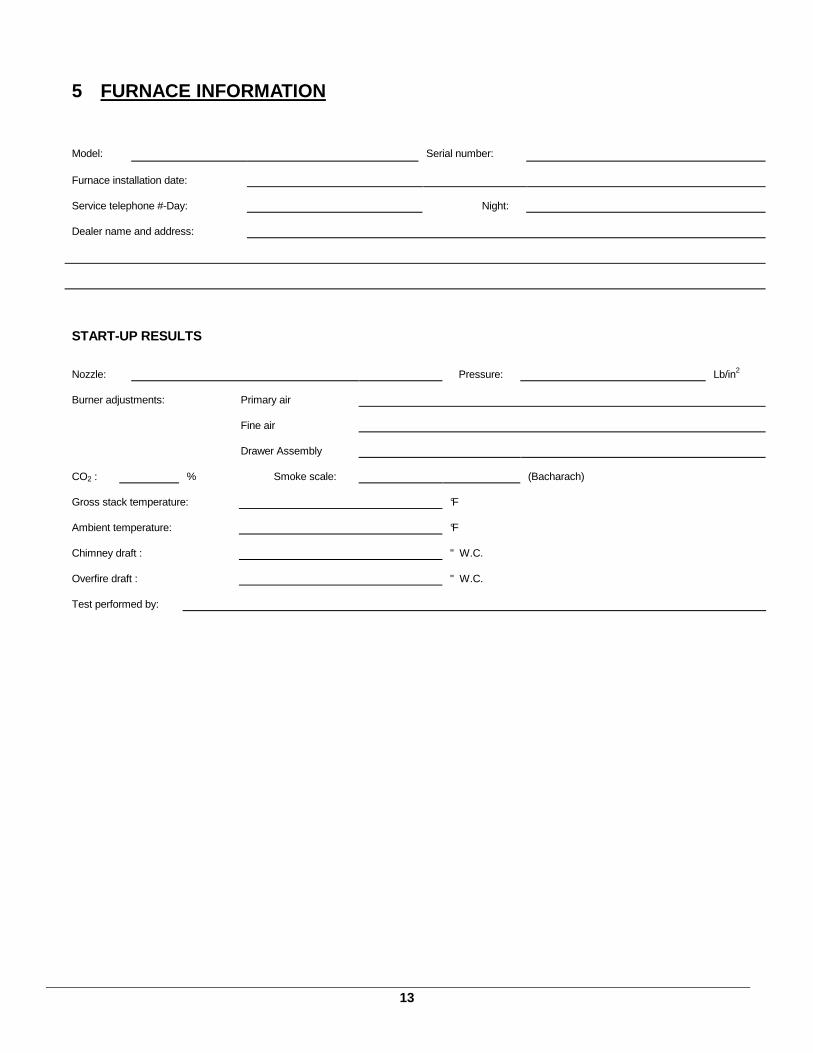
5 FURNACE INFORMATION Model:
Serial number:
Furnace installation date:
Service telephone #-Day:
Night:
Dealer name and address:
START-UP RESULTS
Nozzle:
Pressure:
Lb/in2
Burner adjustments:
Primary air
Fine air
Drawer Assembly
CO2 :
% Smoke scale:
(Bacharach)
Gross stack temperature:
°F
Ambient temperature:
°F
Chimney draft :
" W.C.
Overfire draft :
" W.C.
Test performed by:
14
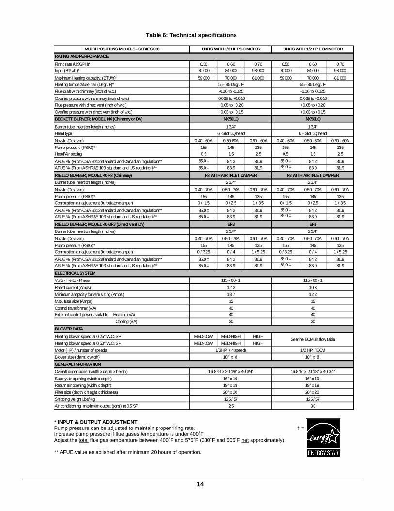
Table 6: Technical specifications
MULTI POSITIONS MODELS - SERIES 098
RATING AND PERFORMANCE
Firing rate (USGPH)* 0.50 0.60 0.70 0.50 0.60 0.70
Input (BTU/h)* 70 000 84 000 98 000 70 000 84 000 98 000
Maximum Heating capacity, (BTU/h)* 59 000 70 000 81 000 59 000 70 000 81 000
Heating temperature rise (Degr. F)*
Flue draft with chimney (inch of w.c.)
Overfire pressure with chimney (inch of w.c.)
Flue pressure with direct vent (inch of w.c.)
Overfire pressure with direct vent (inch of w.c.)
BECKETT BURNER; MODEL NX (Chimney or DV)
Burner tube insertion length (inches)
Head type
Nozzle (Delavan) 0.40 - 60A 0.50 60A 0.60 - 60A 0.40 - 60A 0.50 - 60A 0.60 - 60A
Pump pressure (PSIG)* 155 145 135 155 145 135
Head/Air setting 0.5 1.5 2.5 0.5 1.5 2.5
AFUE % (From CSA B212 standard and Canadian regulation)** 85.0 ‡ 84.2 81.9 85.0 ‡ 84.2 81.9
AFUE % (From ASHRAE 103 standard and US regulation)** 85.0 ‡ 83.9 81.9 85.0 ‡ 83.9 81.9
RIELLO BURNER; MODEL 40-F3 (Chimney)
Burner tube insertion length (inches)
Nozzle (Delavan) 0.40 - 70A 0.50 - 70A 0.60 - 70A 0.40 - 70A 0.50 - 70A 0.60 - 70A
Pump pressure (PSIG)* 155 145 135 155 145 135
Combustion air adjustment (turbulator/damper) 0 / 1.5 0 / 2.5 1 / 3.5 0 / 1.5 0 / 2.5 1 / 3.5
AFUE % (From CSA B212 standard and Canadian regulation)** 85.0 ‡ 84.2 81.9 85.0 ‡ 84.2 81.9
AFUE % (From ASHRAE 103 standard and US regulation)** 85.0 ‡ 83.9 81.9 85.0 ‡ 83.9 81.9
RIELLO BURNER; MODEL 40-BF3 (Direct vent DV)
Burner tube insertion length (inches)
Nozzle (Delavan) 0.40 - 70A 0.50 - 70A 0.60 - 70A 0.40 - 70A 0.50 - 70A 0.60 - 70A
Pump pressure (PSIG)* 155 145 135 155 145 135
Combustion air adjustment (turbulator/damper) 0 / 3.25 0 / 4 1 / 5.25 0 / 3.25 0 / 4 1 / 5.25
AFUE % (From CSA B212 standard and Canadian regulation)** 85.0 ‡ 84.2 81.9 85.0 ‡ 84.2 81.9
AFUE % (From ASHRAE 103 standard and US regulation)** 85.0 ‡ 83.9 81.9 85.0 ‡ 83.9 81.9
ELECTRICAL SYSTEM
Volts - Hertz - Phase
Rated current (Amps)
Minimum ampacity for wire sizing (Amps)
Max. fuse size (Amps)
Control transformer (VA)
External control power available Heating (VA)
Cooling (VA)
BLOWER DATA
Heating blower speed at 0.25" W.C. SP MED-LOW MED-HIGH HIGH
Heating blower speed at 0.50" W.C. SP MED-LOW MED-HIGH HIGH
Motor (HP) / number of speeds
Blower size (diam. x width)
GENERAL INFORMATION
Overall dimensions (width x depth x height)
Supply air opening (width x depth)
Return air opening (width x depth)
Filter size (depth x hieght x thickness)
Shipping weight Lbs/Kg
Air conditioning, maximum output (tons) at 0.5 SP
10'' x 8'' 10'' x 8''
2.5 3.0
20'' x 20'' 20'' x 20''
125 / 57 125 / 57
16'' x 19'' 16'' x 19''
30 30
See the ECM air flow table
1/3 HP / 4 speeds 1/2 HP / ECM
40 40
40 40
115 - 60 - 1 115 - 60 - 1
15 15
10.3
13.7 12.2
12.2
BF3 BF3
2 3/4'' 2 3/4''
F3 WITH AIR INLET DAMPER F3 WITH AIR INLET DAMPER
2 3/4'' 2 3/4''
1 3/4'' 1 3/4''
6 - Slot LQ head 6 - Slot LQ head
-0.035 to +0.010
+0.03 to +0.15
NX56LQ NX56LQ
UNITS WITH 1/3 HP PSC MOTOR UNITS WITH 1/2 HP ECM MOTOR
55 - 85 Degr. F 55 - 85 Degr. F
-0.06 to -0.025 -0.06 to -0.025
-0.035 to +0.010
19'' x 19'' 19'' x 19''
+0.05 to +0.20 +0.05 to +0.20
+0.03 to +0.15
16.875'' x 20 1/8'' x 40 3/4'' 16.875'' x 20 1/8'' x 40 3/4''
* INPUT & OUTPUT ADJUSTMENT Pump pressure can be adjusted to maintain proper firing rate. ‡ = Increase pump pressure if flue gases temperature is under 400˚F Adjust the total flue gas temperature between 400˚F and 575˚F (330˚F and 505˚F net approximately) ** AFUE value established after minimum 20 hours of operation.
15
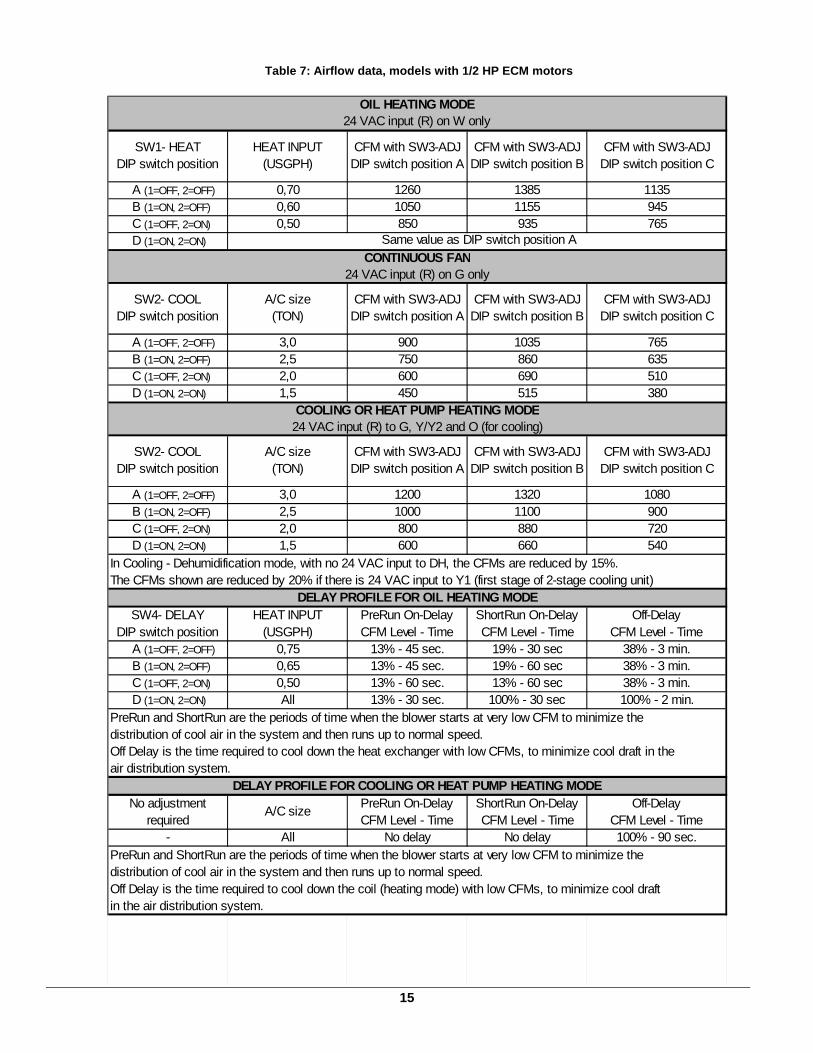
Table 7: Airflow data, models with 1/2 HP ECM motor s
SW1- HEATDIP switch position
HEAT INPUT (USGPH)
CFM with SW3-ADJDIP switch position A
CFM with SW3-ADJDIP switch position B
CFM with SW3-ADJDIP switch position C
A (1=OFF, 2=OFF) 0,70 1260 1385 1135B (1=ON, 2=OFF) 0,60 1050 1155 945C (1=OFF, 2=ON) 0,50 850 935 765D (1=ON, 2=ON)
SW2- COOLDIP switch position
A/C size (TON)
CFM with SW3-ADJDIP switch position A
CFM with SW3-ADJDIP switch position B
CFM with SW3-ADJDIP switch position C
A (1=OFF, 2=OFF) 3,0 900 1035 765B (1=ON, 2=OFF) 2,5 750 860 635C (1=OFF, 2=ON) 2,0 600 690 510D (1=ON, 2=ON) 1,5 450 515 380
SW2- COOLDIP switch position
A/C size (TON)
CFM with SW3-ADJDIP switch position A
CFM with SW3-ADJDIP switch position B
CFM with SW3-ADJDIP switch position C
A (1=OFF, 2=OFF) 3,0 1200 1320 1080B (1=ON, 2=OFF) 2,5 1000 1100 900C (1=OFF, 2=ON) 2,0 800 880 720D (1=ON, 2=ON) 1,5 600 660 540
SW4- DELAYDIP switch position
HEAT INPUT(USGPH)
PreRun On-DelayCFM Level - Time
ShortRun On-DelayCFM Level - Time
Off-DelayCFM Level - Time
A (1=OFF, 2=OFF) 0,75 13% - 45 sec. 19% - 30 sec 38% - 3 min.B (1=ON, 2=OFF) 0,65 13% - 45 sec. 19% - 60 sec 38% - 3 min.C (1=OFF, 2=ON) 0,50 13% - 60 sec. 13% - 60 sec 38% - 3 min.D (1=ON, 2=ON) All 13% - 30 sec. 100% - 30 sec 100% - 2 min.
No adjustmentrequired
A/C sizePreRun On-DelayCFM Level - Time
ShortRun On-DelayCFM Level - Time
Off-DelayCFM Level - Time
- All No delay No delay 100% - 90 sec.PreRun and ShortRun are the periods of time when the blower starts at very low CFM to minimize thedistribution of cool air in the system and then runs up to normal speed.Off Delay is the time required to cool down the coil (heating mode) with low CFMs, to minimize cool draftin the air distribution system.
DELAY PROFILE FOR COOLING OR HEAT PUMP HEATING MODE
PreRun and ShortRun are the periods of time when the blower starts at very low CFM to minimize thedistribution of cool air in the system and then runs up to normal speed. Off Delay is the time required to cool down the heat exchanger with low CFMs, to minimize cool draft in theair distribution system.
DELAY PROFILE FOR OIL HEATING MODE
OIL HEATING MODE24 VAC input (R) on W only
Same value as DIP switch position ACONTINUOUS FAN
24 VAC input (R) on G only
COOLING OR HEAT PUMP HEATING MODE24 VAC input (R) to G, Y/Y2 and O (for cooling)
In Cooling - Dehumidification mode, with no 24 VAC input to DH, the CFMs are reduced by 15%.The CFMs shown are reduced by 20% if there is 24 VAC input to Y1 (first stage of 2-stage cooling unit)
16
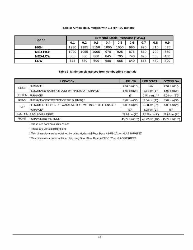
Table 8: Airflow data, models with 1/3 HP PSC motor s
Table 9: Minimum clearances from combustible materi als
UPFLOW HORIZONTAL DOWNFLOW
FURNACE 1 2.54 cm (1") N/A 2.54 cm (1")
PLENUM AND WARM-AIR DUCT WITHIN 6 ft. OF FURNACE 1 5.08 cm (2") 2.54 cm (1") 5.08 cm (2")
BOTTOM FURNACE 2 Ø 2.54 cm (1")3 5.08 cm (2")4
BACK FURNACE (OPPOSITE SIDE OF THE BURNER) 1 7.62 cm (3") 2.54 cm (1") 7.62 cm (3")
PLENUM OR HORIZONTAL WARM-AIR DUCT WITHIN 6 ft. OF FURNACE 2 5.08 cm (2") 5.08 cm (2") 5.08 cm (2")
FURNACE 2 N/A 5.08 cm (2") N/A
FLUE PIPE AROUND FLUE PIPE 22.86 cm (9") 22.86 cm (9") 22.86 cm (9")
FRONT FURNACE (BURNER SIDE) 1 45.72 cm (18") 45.72 cm (18") 45.72 cm (18")
1 These are horizontal dimensions 2 These are vertical dimensions3 This dimension can be obtained by using Horizontal Flow Base # HFB-101 or KLASB0701DET4 This dimension can be obtained by using Dow nflow Base # DFB-102 ro KLASB0801DET
LOCATION
SIDES
TOP
0,1 0,2 0,3 0,4 0,5 0,6 0,7 0,8 0,9
HIGH 1230 1185 1150 1095 1050 990 920 810 595
MED-HIGH 1090 1055 1005 970 925 875 810 700 550
MED-LOW 865 860 860 845 795 740 695 600 460
LOW 675 680 690 680 665 640 565 480 390
External Static Pressure ("W.C.)Speed
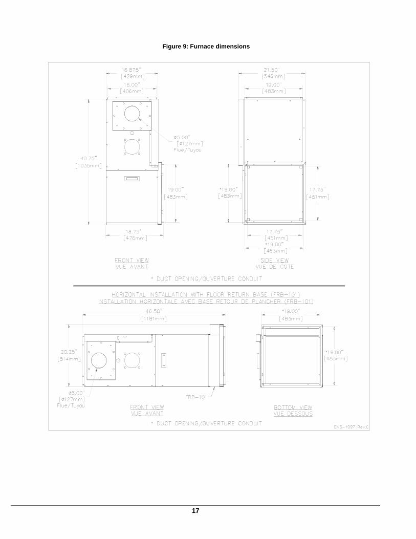
17
Figure 9: Furnace dimensions
18
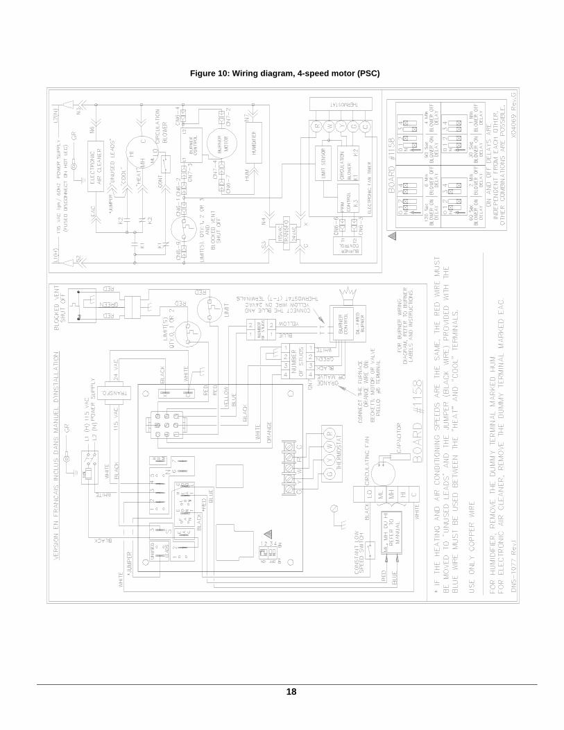
Figure 10: Wiring diagram, 4-speed motor (PSC)
19
Figure 11: Wiring diagram, variable speed motor (EC M)
20
Figure 12: Parts list with 4-speed motor (PSC)
B50064G
21
Table 10: Parts list with 4-speed motor (PSC)
ITEM PART # DESCRIPTION COMMENTS
1 B03409 HEAT EXCHANGER Heat exchanger only2 J06L002 SEAL STRIP, 1/4 x 1/8 x 25'3 B03429 WIRE CHANNEL, INT.4 B03420-01 FRONT PANEL ASSEMBLY Panel, insulation and labels included5 B03444 FRONT PANEL INSULATION6 B03450-01 BAFFLE, LATERAL7 B03426-01 SIDE PANEL ASSEMBLY (RIGHT) Panel, insulation and baffle included8 B03473 SIDE PANEL INSULATION9 L04J001 CABLE CLAMP, 9/16" WHITE10 F06F015 WASHER, ZINC 1 7/16"11 Z99F061 OBSERVATION PORT12 L04I013 STRAIN RELIEF BUSHING13 B03448 WIRE CHANNEL (BVSO/SWITCH)14 B03455-01 ELECTRICAL KIT, BVSO INT.15 L07F003 ROCKER SWITCH, SPST16 R02R006 HIGH LIMIT 36T01B7 150-20F, 7"17 B03454 ELECTRICAL KIT, BURNER18 B03453 ELECTRICAL KIT, TT19 B03472 BAFFLE One baffle included20 B03416 RADIATOR BAFFLE Item # 52 included21 F07O001 FLANGE NUT, HEXAGONAL 3/8-16NC BRASS22 F07F011 HEX NUT 3/8-16NC ZINC 23 Z99F050 HANDLE , RECESSED BLACK24 B03419 BLOWER DOOR ASSEMBLY Door and labels included25 B03439 COVER, ELECTRICAL BOX26 B03535-01 REPLACEMENT BLOWER ASSEMBLY Blower, motor and capacitor included27 Z06G001 BLOCKED VENT SHUT-OFF BVSO-22528 B03118-01 ELECTRICAL KIT, BVSO EXT.29 B03470 FLOOR30 B03426-02 SIDE PANEL ASSEMBLY (LEFT) Panel, insulation and baffle included31 B03480 FILTER RACK KIT32 B03450-02 LATERAL BAFFLE33 B30513 BLOWER SLIDE One slide included34 B03441 BLOWER DIVIDER35 B03451 REAR BAFFLE36 B03427 REAR PANEL ASSEMBLY Panel, insulation and baffles included37 B03471 REAR PANEL INSULATION38 B03457-01 ELECTRICAL KIT, BLOWER39 L01I001 CAPACITOR 5MF40 B01024 CAPACITOR HOLDER41 B03456 ELECTRICAL KIT, BOARD42A R99G004 ELECTRONIC BOARD, UTEC 1158-11042B R99G002 ELECTRONIC BOARD, HONEYWELL ST9103A43 B03440 ELECTRICAL BOX44 L01F009 TRANSFORMER, 120-24Volt, 40VA45 B03438 SUPPORT, ELECTRONICS BOX46 R02R007 HIGH LIMIT, 120-20F, 1.75''47 B03437 BLOWER SLIDE One slide included48 B03720-02 BLOWER, 100-8R DD 0,50 PP Housing, wheel and label only49 B01888 MOTOR SUPPORT ASSEMBLY Legs, band and hardware included50 B01890-01 MOTOR ASSEMBLY, 1/3 HP Complete with legs51 B03428 SMOKE OUTLET GASKET
DOWNFLOW BASE B03464-01
HORIZONTAL FLOW BASE B00488-01
FILTER ADAPTOR B03482-01
VENT TERMINAL KIT 4'' For sealed combustion
4" INSULATED FLEX VENT 10ft For sealed combustion
4" INSULATED FLEX VENT 20ft For sealed combustion
BECKETT NX BURNER (0.50-60A NOZZLE)
RIELLO 40-F3 BURNER (0.50-70A NOZZLE)
RIELLO 40-BF3 BURNER (0.50-70A NOZZLE) For sealed combustion
PROTECTION PLATE BURNER NX For down flow instalation onlyB03789
N01F055 KLABR201RLO
N01J050 KLABR0101BEC
N01F054 KLABR101RLO
IFV098-10KLAFV0101DET
IFV098-20KLAFV0201DET
HFB-101KLASB0701DET
VTK-098KLAVT0101DET
FRB-101KLARB0101DET
ACCESSORIES
DFB-102KLASB0801DET
B50064I
22
Figure 13: Parts list with variable speed motor (EC M)
B50074G
23
Table 11: Parts list with variable speed motor (ECM )
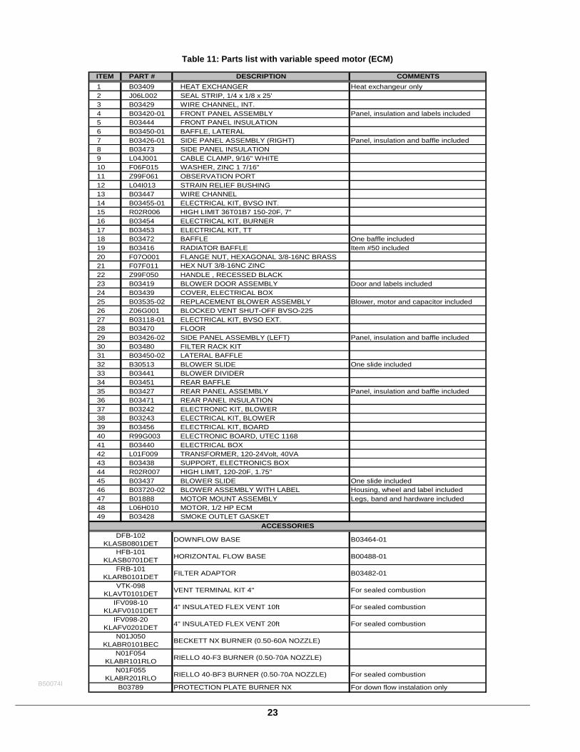
ITEM PART # DESCRIPTION COMMENTS
1 B03409 HEAT EXCHANGER Heat exchangeur only 2 J06L002 SEAL STRIP, 1/4 x 1/8 x 25'3 B03429 WIRE CHANNEL, INT.4 B03420-01 FRONT PANEL ASSEMBLY Panel, insulation and labels included5 B03444 FRONT PANEL INSULATION6 B03450-01 BAFFLE, LATERAL7 B03426-01 SIDE PANEL ASSEMBLY (RIGHT) Panel, insulation and baffle included8 B03473 SIDE PANEL INSULATION9 L04J001 CABLE CLAMP, 9/16" WHITE10 F06F015 WASHER, ZINC 1 7/16"11 Z99F061 OBSERVATION PORT12 L04I013 STRAIN RELIEF BUSHING13 B03447 WIRE CHANNEL14 B03455-01 ELECTRICAL KIT, BVSO INT.15 R02R006 HIGH LIMIT 36T01B7 150-20F, 7"16 B03454 ELECTRICAL KIT, BURNER17 B03453 ELECTRICAL KIT, TT18 B03472 BAFFLE One baffle included19 B03416 RADIATOR BAFFLE Item #50 included20 F07O001 FLANGE NUT, HEXAGONAL 3/8-16NC BRASS21 F07F011 HEX NUT 3/8-16NC ZINC 22 Z99F050 HANDLE , RECESSED BLACK23 B03419 BLOWER DOOR ASSEMBLY Door and labels included24 B03439 COVER, ELECTRICAL BOX25 B03535-02 REPLACEMENT BLOWER ASSEMBLY Blower, motor and capacitor included26 Z06G001 BLOCKED VENT SHUT-OFF BVSO-22527 B03118-01 ELECTRICAL KIT, BVSO EXT.28 B03470 FLOOR29 B03426-02 SIDE PANEL ASSEMBLY (LEFT) Panel, insulation and baffle included30 B03480 FILTER RACK KIT31 B03450-02 LATERAL BAFFLE32 B30513 BLOWER SLIDE One slide included33 B03441 BLOWER DIVIDER34 B03451 REAR BAFFLE35 B03427 REAR PANEL ASSEMBLY Panel, insulation and baffle included36 B03471 REAR PANEL INSULATION37 B03242 ELECTRONIC KIT, BLOWER38 B03243 ELECTRICAL KIT, BLOWER39 B03456 ELECTRICAL KIT, BOARD40 R99G003 ELECTRONIC BOARD, UTEC 116841 B03440 ELECTRICAL BOX42 L01F009 TRANSFORMER, 120-24Volt, 40VA43 B03438 SUPPORT, ELECTRONICS BOX44 R02R007 HIGH LIMIT, 120-20F, 1.75''45 B03437 BLOWER SLIDE One slide included46 B03720-02 BLOWER ASSEMBLY WITH LABEL Housing, wheel and label included47 B01888 MOTOR MOUNT ASSEMBLY Legs, band and hardware included48 L06H010 MOTOR, 1/2 HP ECM49 B03428 SMOKE OUTLET GASKET
DOWNFLOW BASE B03464-01
HORIZONTAL FLOW BASE B00488-01
FILTER ADAPTOR B03482-01
VENT TERMINAL KIT 4'' For sealed combustion
4" INSULATED FLEX VENT 10ft For sealed combustion
4" INSULATED FLEX VENT 20ft For sealed combustion
BECKETT NX BURNER (0.50-60A NOZZLE)
RIELLO 40-F3 BURNER (0.50-70A NOZZLE)
RIELLO 40-BF3 BURNER (0.50-70A NOZZLE) For sealed combustion
PROTECTION PLATE BURNER NX For down flow instalation onlyB03789
N01F055 KLABR201RLO
N01J050 KLABR0101BEC
N01F054 KLABR101RLO
IFV098-10KLAFV0101DET
IFV098-20KLAFV0201DET
HFB-101KLASB0701DET
VTK-098KLAVT0101DET
FRB-101KLARB0101DET
ACCESSORIESDFB-102
KLASB0801DET
B50074I