Embed Size (px)
Citation preview
© 2005 Petr Grygarek, Advanced Computer Networks Technologies 1
Multiprotocol Label Multiprotocol Label SwitchingSwitching(MPLS)(MPLS)
Petr GrygPetr Grygáárekrek
2© 2005 Petr Grygarek, Advanced Computer Networks Technologies
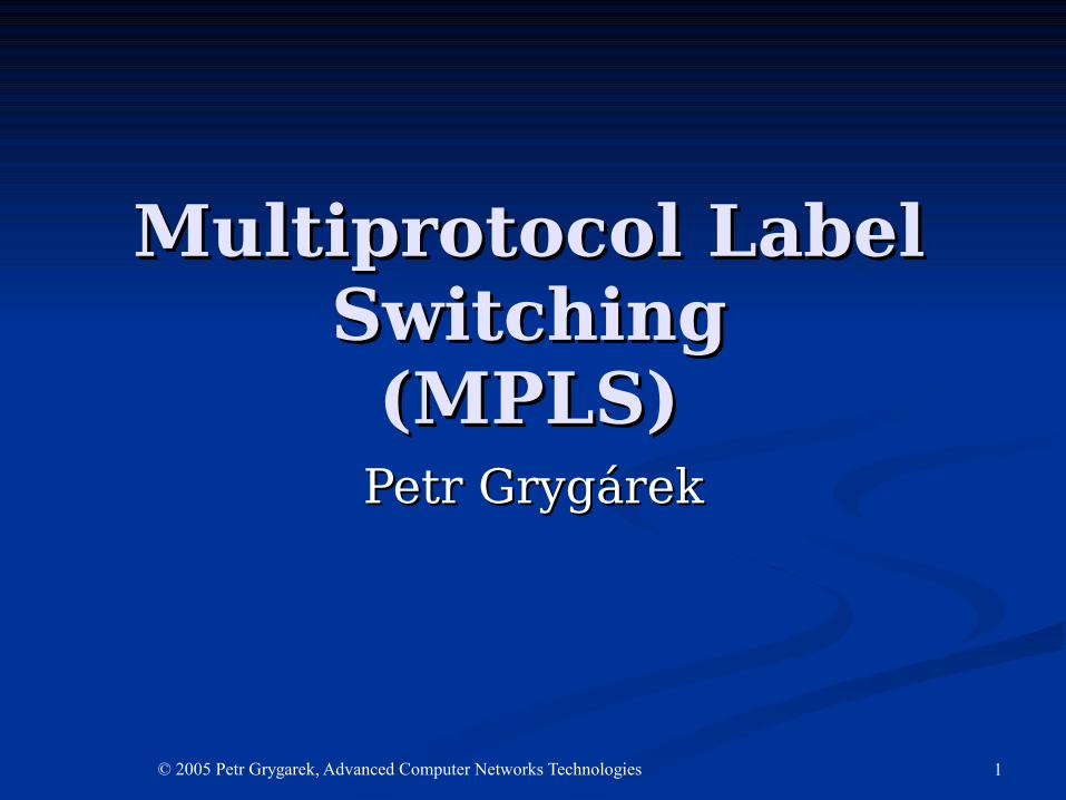
Technology BasicsTechnology Basics• Integrates label-based forwarding paradigm with network layer
routing
• label forwarding + label swapping similar to ATM/FR
• switching tables constructed using IP routing protocol(s)
• Advantages:
• improves the price/performance of network layer routing•MPLS switching algorithm simpler and faster than IP routing
•Processor-intensive packet analysis and classification happens only once at the ingress edge
•But MPLS is not But MPLS is not onlyonly a method to make routers much more faster a method to make routers much more faster
• improves the scalability of the network layer•(slow lookup of huge IP routing tables etc.)
• provides greater flexibility in the delivery of (new) routing services •new routing services may be added without change to the
forwarding paradigm• Multiple VRF-based VPNs, traffic-engineering,…
• integrates IP routing with VC-based networks (like ATM)
3© 2005 Petr Grygarek, Advanced Computer Networks Technologies
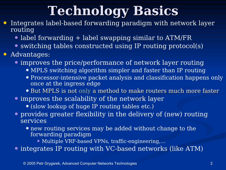
MPLS Operation in BriefMPLS Operation in Brief• Standard IP routing protocol used in MPLS routing Standard IP routing protocol used in MPLS routing
domain domain • (OSPF, IS-IS, …)(OSPF, IS-IS, …)
• <IP prefix, label > mapping created by egress router<IP prefix, label > mapping created by egress router• i.e. router at MPLS domain edge used as exit point i.e. router at MPLS domain edge used as exit point
for that IP prefixfor that IP prefix• Label distribution protocols used to distribute label Label distribution protocols used to distribute label
bindings for IP prefixes between adjacent neighborsbindings for IP prefixes between adjacent neighbors• label has local significancelabel has local significance
• Ingress LSR receives IP packetsIngress LSR receives IP packets• Performs classification and assigns labelPerforms classification and assigns label• Forwards labeled packet to MPLS coreForwards labeled packet to MPLS core
• Core LSRs switch labeled packets based on label Core LSRs switch labeled packets based on label valuevalue
• Egress router removes label before forwarding Egress router removes label before forwarding packet out of MPLS domainpacket out of MPLS domain• performs normal L3 routing table lookupperforms normal L3 routing table lookup
4© 2005 Petr Grygarek, Advanced Computer Networks Technologies
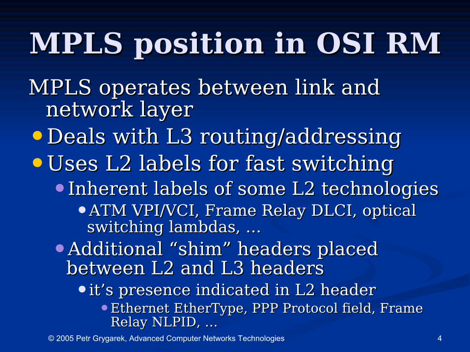
MPLS position in OSI RMMPLS position in OSI RMMPLS operates between link and MPLS operates between link and
network layernetwork layer
•Deals with L3 routing/addressingDeals with L3 routing/addressing
•Uses L2 labels for fast switchingUses L2 labels for fast switching•Inherent labels of some L2 technologiesInherent labels of some L2 technologies
•ATM VPI/VCI, Frame Relay DLCI, optical ATM VPI/VCI, Frame Relay DLCI, optical switching lambdas, …switching lambdas, …
•Additional “shim” headers placed Additional “shim” headers placed between L2 and L3 headersbetween L2 and L3 headers•it’s presence indicated in L2 headerit’s presence indicated in L2 header
•Ethernet EtherType, PPP Protocol field, Frame Ethernet EtherType, PPP Protocol field, Frame Relay NLPID, …Relay NLPID, …
5© 2005 Petr Grygarek, Advanced Computer Networks Technologies
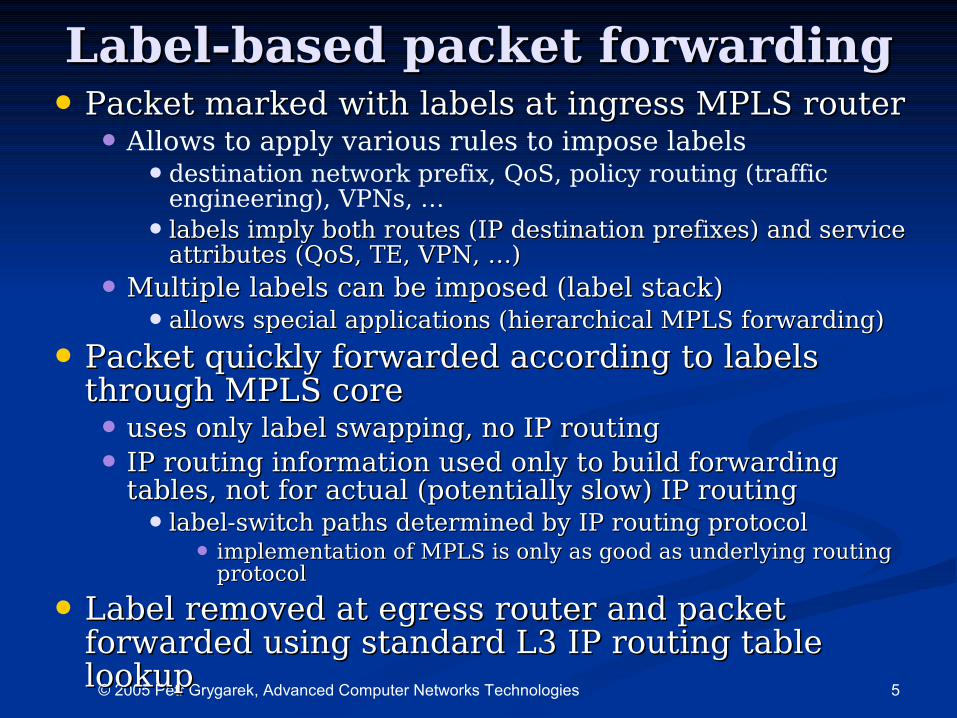
Label-based packet forwardingLabel-based packet forwarding• Packet marked with labels at ingress MPLS routerPacket marked with labels at ingress MPLS router
• Allows to apply various rules to impose labels •destination network prefix, QoS, policy routing (traffic
engineering), VPNs, …
• labels imply both routes (IP destination prefixes) and service labels imply both routes (IP destination prefixes) and service attributes (QoS, TE, VPN, …)attributes (QoS, TE, VPN, …)
• Multiple labels can be imposed (label stack)Multiple labels can be imposed (label stack)•allows special applications (hierarchical MPLS forwarding)allows special applications (hierarchical MPLS forwarding)
• Packet quickly forwarded according to labels Packet quickly forwarded according to labels through MPLS corethrough MPLS core• uses only label swapping, no IP routinguses only label swapping, no IP routing
• IP routing information used only to build forwarding IP routing information used only to build forwarding tables, not for actual (potentially slow) IP routingtables, not for actual (potentially slow) IP routing• label-switch paths determined by IP routing protocollabel-switch paths determined by IP routing protocol
• implementation of MPLS is only as good as underlying routing implementation of MPLS is only as good as underlying routing protocolprotocol
• Label removed at egress router and packet Label removed at egress router and packet forwarded using standard L3 IP routing table forwarded using standard L3 IP routing table lookuplookup
6© 2005 Petr Grygarek, Advanced Computer Networks Technologies
Components of MPLS Components of MPLS architecturearchitecture
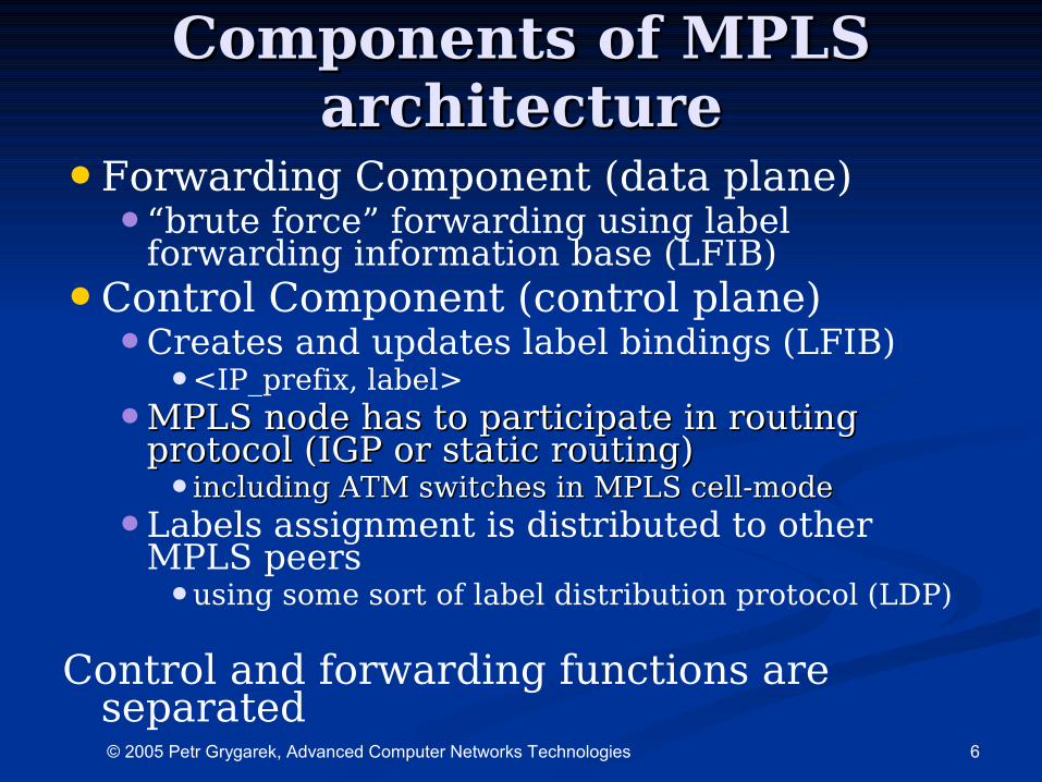
•Forwarding Component (data plane)•“brute force” forwarding using label
forwarding information base (LFIB)
•Control Component (control plane)•Creates and updates label bindings (LFIB)
•<IP_prefix, label>
•MPLS node has to participate in routing MPLS node has to participate in routing protocol (IGP or static routing)protocol (IGP or static routing)•including ATM switches in MPLS cell-modeincluding ATM switches in MPLS cell-mode
•Labels assignment is distributed to other MPLS peers•using some sort of label distribution protocol (LDP)
Control and forwarding functions are separated
7© 2005 Petr Grygarek, Advanced Computer Networks Technologies
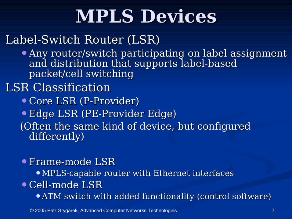
MPLS DevicesMPLS DevicesLabel-Switch Router (LSR)Label-Switch Router (LSR)
•Any router/switch participating on label assignment Any router/switch participating on label assignment and distribution that supports label-based and distribution that supports label-based packet/cell switchingpacket/cell switching
LSR ClassificationLSR Classification•Core LSR (P-Provider)Core LSR (P-Provider)
•Edge LSR (PE-Provider Edge)Edge LSR (PE-Provider Edge)(Often the same kind of device, but configured (Often the same kind of device, but configured
differently)differently)
•Frame-mode LSRFrame-mode LSR•MPLS-capable router with Ethernet interfacesMPLS-capable router with Ethernet interfaces
•Cell-mode LSRCell-mode LSR•ATM switch with added functionality (control software)ATM switch with added functionality (control software)
8© 2005 Petr Grygarek, Advanced Computer Networks Technologies
Functions of Edge LSRFunctions of Edge LSR
•Any LSR on MPLS domain edge, i.e. with Any LSR on MPLS domain edge, i.e. with non-MPLS neighboring devicesnon-MPLS neighboring devices
•Performs label imposition and dispositionPerforms label imposition and disposition•Packets classified and label imposedPackets classified and label imposed
•Classification based on routing and policy Classification based on routing and policy requirementsrequirements•Traffic engineering, policy routing, QoS-based Traffic engineering, policy routing, QoS-based
routingrouting
•Information of L3 (and above) headers Information of L3 (and above) headers inspected only once at edge of the MPLS inspected only once at edge of the MPLS domaindomain
9© 2005 Petr Grygarek, Advanced Computer Networks Technologies
Forwarding Equivalence Class (FEC)
•Packets classified into FECs at Packets classified into FECs at MPLS domain edge LSRMPLS domain edge LSR•according unicast routing destinations, according unicast routing destinations,
QoS class, VPN, multicast group, traffic-QoS class, VPN, multicast group, traffic-engineered traffic class, …engineered traffic class, …
•FEC is a class of packets to be FEC is a class of packets to be MPLS-switched the same wayMPLS-switched the same way
10© 2005 Petr Grygarek, Advanced Computer Networks Technologies
Label switching path (LSP)Label switching path (LSP)
•Sequence of LSRs between ingress Sequence of LSRs between ingress and egress (edge) LSRsand egress (edge) LSRs•+ sequence of assigned labels (local + sequence of assigned labels (local
significance)significance)
•UnidirectionalUnidirectional
•For every forward equivalence classFor every forward equivalence class
•May diverge from IGP shortest pathMay diverge from IGP shortest path•Path established by traffic engineering Path established by traffic engineering
using explicit routing and label switching using explicit routing and label switching paths tunnels paths tunnels
11© 2005 Petr Grygarek, Advanced Computer Networks Technologies
Upstream and downstream Upstream and downstream neighborsneighbors
•From perspective of some particular LSRFrom perspective of some particular LSR
•Related to particular destination (and Related to particular destination (and FEC)FEC)
•Routing protocol’s Next-hop address Routing protocol’s Next-hop address determines downstream neighbordetermines downstream neighbor
Upstream neighbor is closer to data source Upstream neighbor is closer to data source whereas downstream neighbor is closer to whereas downstream neighbor is closer to the destination networkthe destination network
12© 2005 Petr Grygarek, Advanced Computer Networks Technologies
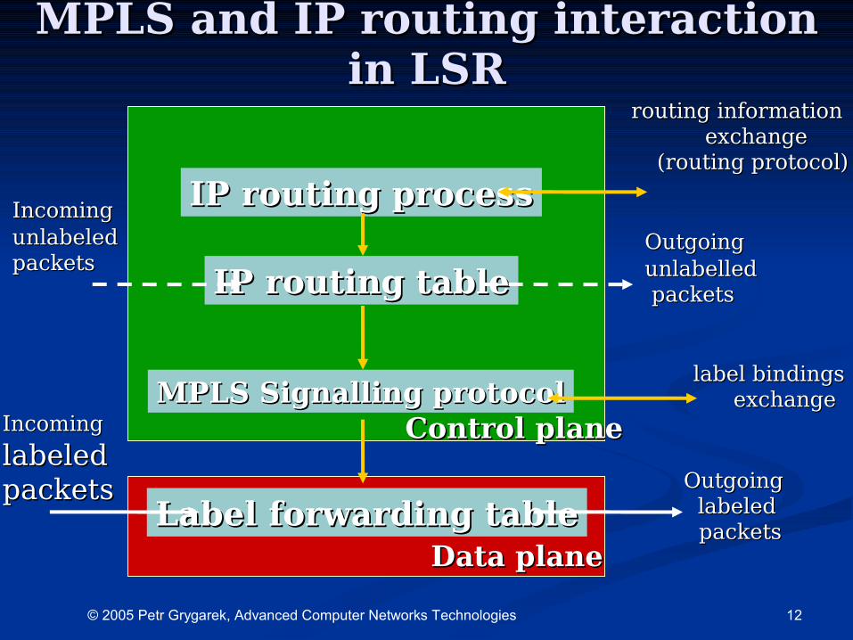
MPLS and IP routing interaction MPLS and IP routing interaction in LSRin LSR
IP routing tableIP routing table
IP routing processIP routing process
MPLS Signalling protocolMPLS Signalling protocol
Label forwarding tableLabel forwarding table
routing informationrouting information exchange exchange
(routing protocol)(routing protocol)
label bindingslabel bindingsexchangeexchange
Outgoing Outgoing labeledlabeled packets packets
IncomingIncoming
labeledlabeledpacketspackets
IncomingIncomingunlabeledunlabeledpacketspackets
OutgoingOutgoingunlabelledunlabelled packets packets
Control planeControl plane
Data planeData plane
13© 2005 Petr Grygarek, Advanced Computer Networks Technologies
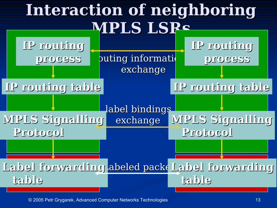
Interaction of neighboring Interaction of neighboring MPLS LSRsMPLS LSRs
Routing informationRouting informationexchangeexchange
label bindingslabel bindingsexchangeexchange
Labeled packetsLabeled packets
IP routing tableIP routing table
IP routingIP routingprocessprocess
MPLS SignallingMPLS SignallingProtocolProtocol
Label forwardingLabel forwardingtabletable
IP routing tableIP routing table
IP routingIP routingprocessprocess
MPLS SignallingMPLS SignallingProtocolProtocol
Label forwardingLabel forwardingtabletable
14© 2005 Petr Grygarek, Advanced Computer Networks Technologies
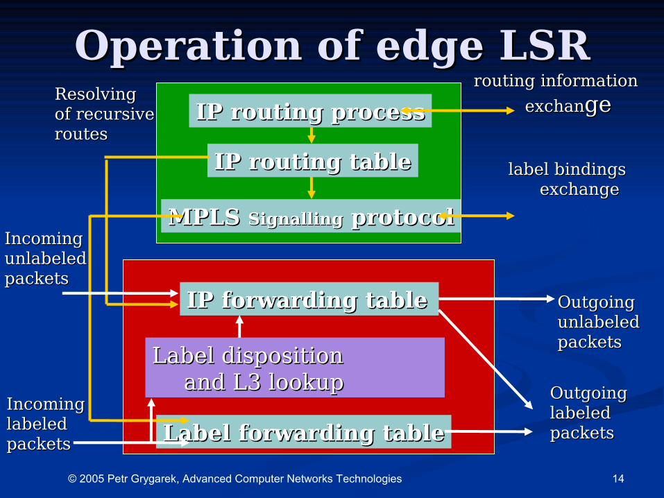
Operation of edge LSROperation of edge LSR
IP routing tableIP routing table
IP routing processIP routing process
MPLS MPLS SignallingSignalling protocol protocol
Label forwarding tableLabel forwarding table
routing informationrouting information
exchanexchangege
label bindingslabel bindingsexchangeexchange
OutgoingOutgoinglabeledlabeledpacketspackets
IncomingIncomingunlabeledunlabeledpacketspackets
OutgoingOutgoingunlabeledunlabeledpacketspackets
IP forwarding tableIP forwarding table
Label dispositionLabel disposition and L3 lookup and L3 lookup
IncomingIncominglabeledlabeledpacketspackets
ResolvingResolvingof recursiveof recursiveroutesroutes
15© 2005 Petr Grygarek, Advanced Computer Networks Technologies
Penultimate hop behaviorPenultimate hop behaviorLabel at the top of label stack is removed not by egress Label at the top of label stack is removed not by egress
routes at MPLS domain edge (as could be expected), routes at MPLS domain edge (as could be expected), but by it’s upstream neighbor (penultimate hop)but by it’s upstream neighbor (penultimate hop)
•On egress router, packet could not be label-On egress router, packet could not be label-switched anywayswitched anyway
•Egress router has to perform L3 lookup to find Egress router has to perform L3 lookup to find more specific routemore specific route•commonly, egress router advertises single label for commonly, egress router advertises single label for
summary routesummary route
•Disposition of label imposed by egress router’s Disposition of label imposed by egress router’s upstream neighbor would introduce unnecessary upstream neighbor would introduce unnecessary overheadoverhead
•For that reason, upstream neighbor of egress For that reason, upstream neighbor of egress router always pops label and sends packet to router always pops label and sends packet to egress router unlabeledegress router unlabeled•Egress LSR requests popping of label through label Egress LSR requests popping of label through label
distribution protocoldistribution protocol•advertises “implicit-null” label for particular FECadvertises “implicit-null” label for particular FEC
16© 2005 Petr Grygarek, Advanced Computer Networks Technologies
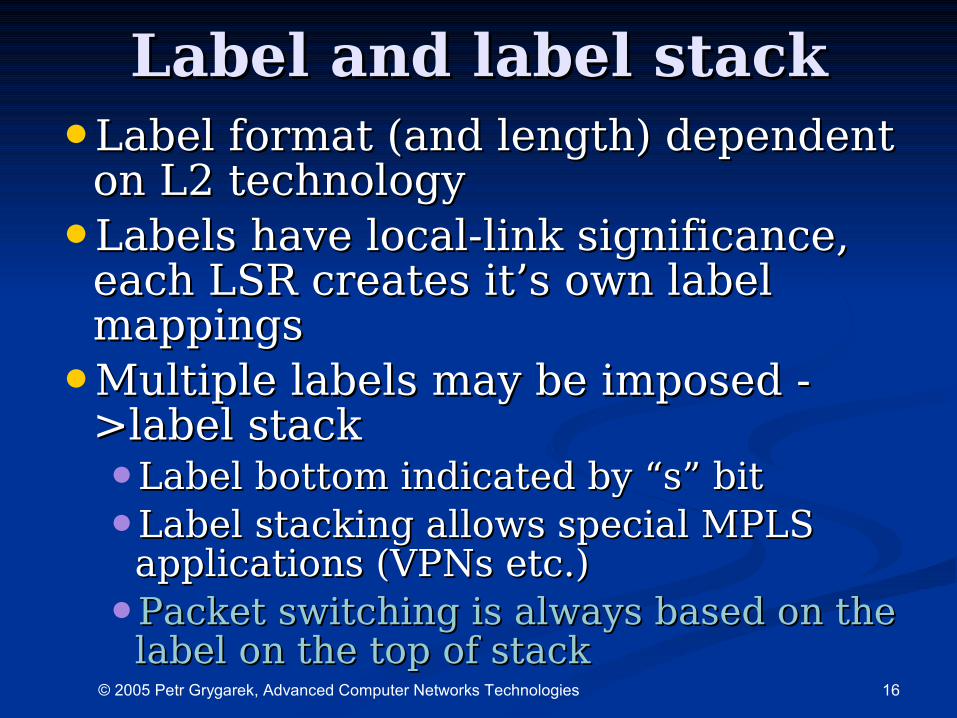
Label and label stackLabel and label stack•Label format (and length) dependent Label format (and length) dependent
on L2 technologyon L2 technology
•Labels have local-link significance, Labels have local-link significance, each LSR creates it’s own label each LSR creates it’s own label mappingsmappings
•Multiple labels may be imposed - Multiple labels may be imposed - >label stack>label stack•Label bottom indicated by “s” bitLabel bottom indicated by “s” bit
•Label stacking allows special MPLS Label stacking allows special MPLS applications (VPNs etc.)applications (VPNs etc.)
•Packet switching is always based on the Packet switching is always based on the label on the top of stacklabel on the top of stack

17© 2005 Petr Grygarek, Advanced Computer Networks Technologies
MPLS headerMPLS header
•Between L2 and L3 headerBetween L2 and L3 header•MPLS header presence indicated in MPLS header presence indicated in
EtherType/PPP Protocol ID/Frame Relay EtherType/PPP Protocol ID/Frame Relay NLPIDNLPID
•4 octets (32b)4 octets (32b)•20 bits – label value20 bits – label value
•3 bits Exp (experimental) – sometimes 3 bits Exp (experimental) – sometimes used for QoSused for QoS
•8 bits MPLS TTL (Time to Live)8 bits MPLS TTL (Time to Live)
•1 bit – “S bit” – indicates bottom of 1 bit – “S bit” – indicates bottom of stackstack
18© 2005 Petr Grygarek, Advanced Computer Networks Technologies
Label Bindings Label Bindings DistributionDistribution
19© 2005 Petr Grygarek, Advanced Computer Networks Technologies
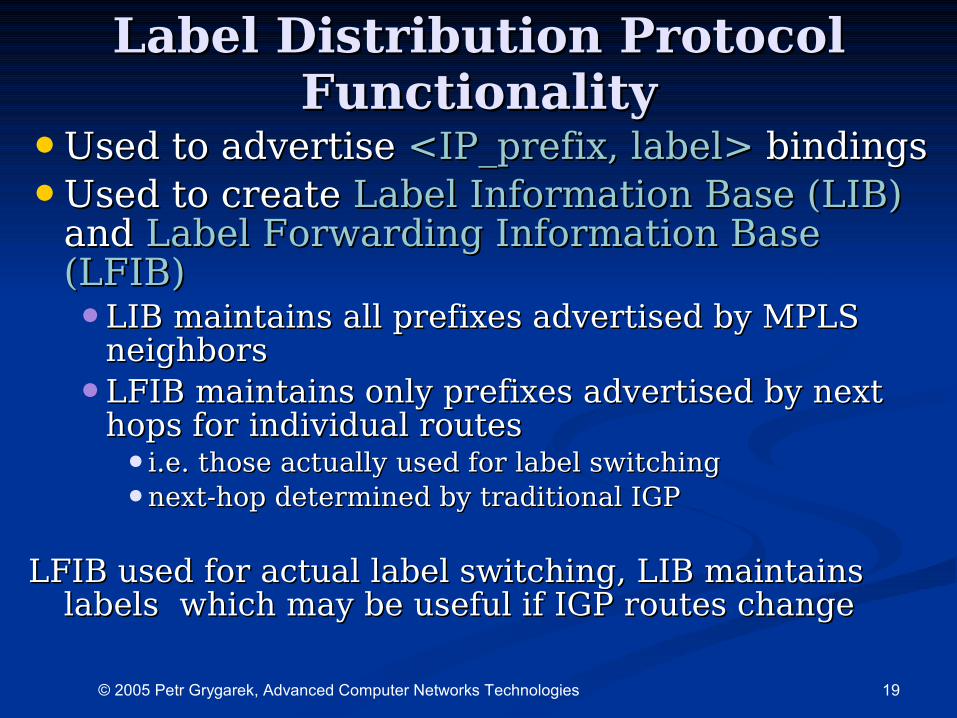
Label Distribution Protocol Label Distribution Protocol FunctionalityFunctionality
•Used to advertise Used to advertise <<IPIP__prefixprefix,, label label>> bindingbindingss
•Used to create Used to create LLabel abel Information Base (LIB)Information Base (LIB) and and Label FLabel Forwarding orwarding IInformation nformation BBase ase (LFIB)(LFIB)•LIB maintains all prefixes advertised by MPLS LIB maintains all prefixes advertised by MPLS
neighborsneighbors
•LFIB maintains only prefixes advertised by next LFIB maintains only prefixes advertised by next hops for individual routeshops for individual routes•i.e. those actually used for label switchingi.e. those actually used for label switching
•next-hop determined by traditional IGP next-hop determined by traditional IGP
LFIB used for actual label switching, LIB maintains LFIB used for actual label switching, LIB maintains labels which may be useful if IGP routes changelabels which may be useful if IGP routes change
20© 2005 Petr Grygarek, Advanced Computer Networks Technologies
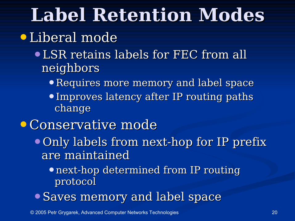
Label Retention ModesLabel Retention Modes•Liberal modeLiberal mode
•LSR retains labels for FEC from all LSR retains labels for FEC from all neighborsneighbors•Requires more memory and label spaceRequires more memory and label space
•Improves latency after IP routing paths Improves latency after IP routing paths changechange
•Conservative modeConservative mode•Only labels from next-hop for IP prefix Only labels from next-hop for IP prefix
are maintainedare maintained•next-hop determined from IP routing next-hop determined from IP routing
protocolprotocol
•Saves memory and label spaceSaves memory and label space
21© 2005 Petr Grygarek, Advanced Computer Networks Technologies
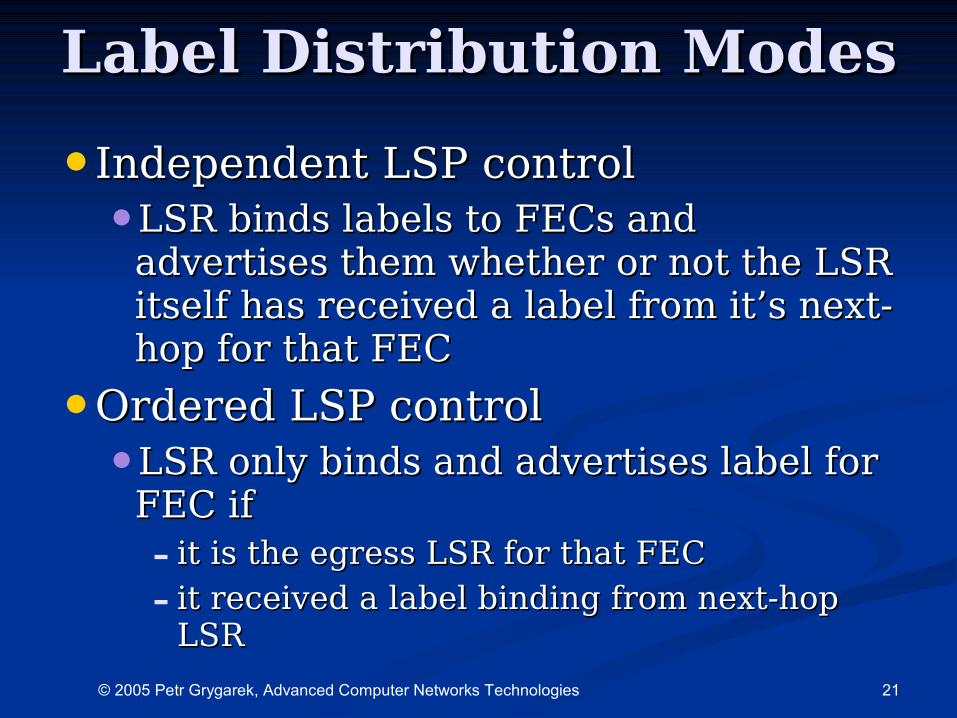
Label Distribution ModesLabel Distribution Modes
•Independent LSP controlIndependent LSP control•LSR binds labels to FECs and LSR binds labels to FECs and
advertises them whether or not the LSR advertises them whether or not the LSR itself has received a label from it’s next-itself has received a label from it’s next-hop for that FEChop for that FEC
•Ordered LSP controlOrdered LSP control•LSR only binds and advertises label for LSR only binds and advertises label for
FEC ifFEC if- it is the egress LSR for that FECit is the egress LSR for that FEC
- it received a label binding from next-hop it received a label binding from next-hop LSRLSR
22© 2005 Petr Grygarek, Advanced Computer Networks Technologies
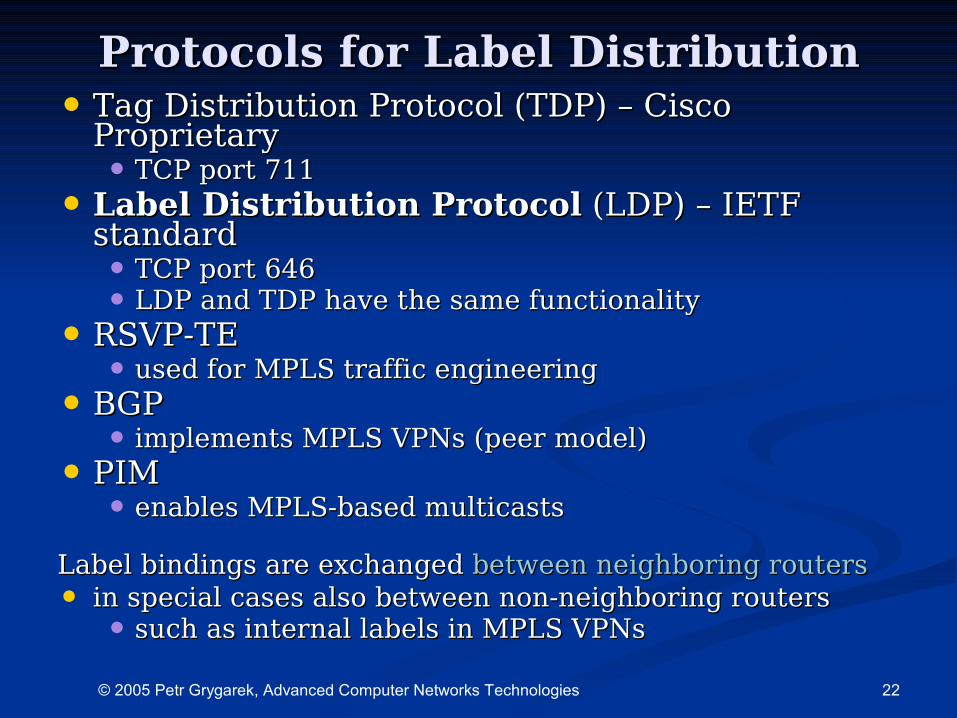
Protocols for Label DistributionProtocols for Label Distribution• Tag Distribution Protocol (TDP) – Cisco Tag Distribution Protocol (TDP) – Cisco
ProprietaryProprietary• TCP port 711TCP port 711
• Label Distribution ProtocolLabel Distribution Protocol (LDP) – IETF (LDP) – IETF standardstandard• TCP port 646TCP port 646• LDP and TDP have the same functionalityLDP and TDP have the same functionality
• RSVP-TERSVP-TE• used for MPLS traffic engineeringused for MPLS traffic engineering
• BGPBGP• implements MPLS VPNs (peer model)implements MPLS VPNs (peer model)
• PIMPIM• enables MPLS-based multicastsenables MPLS-based multicasts
Label bindings are exchanged Label bindings are exchanged between neighboring routersbetween neighboring routers• in special cases also between non-neighboring routers in special cases also between non-neighboring routers
• such as internal labels in MPLS VPNssuch as internal labels in MPLS VPNs
23© 2005 Petr Grygarek, Advanced Computer Networks Technologies
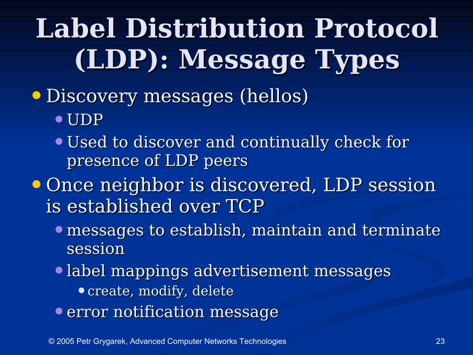
Label Distribution Protocol Label Distribution Protocol (LDP): Message Types(LDP): Message Types
•Discovery messages (hellos)Discovery messages (hellos)•UDPUDP
•Used to discover and continually check for Used to discover and continually check for presence of LDP peerspresence of LDP peers
•Once neighbor is discovered, LDP session Once neighbor is discovered, LDP session is established over TCPis established over TCP•messages to establish, maintain and terminate messages to establish, maintain and terminate
sessionsession
•label mappings advertisement messages label mappings advertisement messages •create, modify, deletecreate, modify, delete
•error notification messageerror notification message
24© 2005 Petr Grygarek, Advanced Computer Networks Technologies
Frame-mode and Cell-mode Frame-mode and Cell-mode LSRsLSRs
25© 2005 Petr Grygarek, Advanced Computer Networks Technologies
Frame-mode LSRsFrame-mode LSRs
•Frame/Packet processing devicesFrame/Packet processing devices•such as routers or Frame Relay such as routers or Frame Relay
switchesswitches
•Labeled packets treated as L2 Labeled packets treated as L2 framesframes•Shim header between L2 and L3 headerShim header between L2 and L3 header
•Presence of MPLS header indicated in Presence of MPLS header indicated in L2 header L2 header
26© 2005 Petr Grygarek, Advanced Computer Networks Technologies
Frame-mode Label Frame-mode Label DistributionDistribution
•Unsolicited downstreamUnsolicited downstream•Labels distributed automatically to upstream Labels distributed automatically to upstream
neighborsneighbors
•Downstream LSR advertises labels for Downstream LSR advertises labels for particular FECs to the upstream neighborparticular FECs to the upstream neighbor
•Independent control of label assignmentIndependent control of label assignment•Label assigned as soon as new IP prefix Label assigned as soon as new IP prefix
appears in IP routing tableappears in IP routing table•Mapping stored into LIBMapping stored into LIB
•LSR may send (switch) labeled packets to next LSR may send (switch) labeled packets to next hop even if next-hop itself does not have label hop even if next-hop itself does not have label for switching that FEC furtherfor switching that FEC further
•Liberal retention mode Liberal retention mode •All received label mappings are retainedAll received label mappings are retained
27© 2005 Petr Grygarek, Advanced Computer Networks Technologies
Cell-mode LSRsCell-mode LSRsATM switchesATM switches
•LSRs switch cells, not packetsLSRs switch cells, not packets•packets fragmented into cellspackets fragmented into cells
•VPI/VCI used to carry labelsVPI/VCI used to carry labels
•Additional piece of software needed Additional piece of software needed to integrate ATM switches with IP to integrate ATM switches with IP routing (IGP) and implement label routing (IGP) and implement label distribution protocols - Label Switch distribution protocols - Label Switch ControllerController•needed to provide label assignment and needed to provide label assignment and
distribution and proper building of distribution and proper building of switching tables (ATM layer)switching tables (ATM layer)
28© 2005 Petr Grygarek, Advanced Computer Networks Technologies
Limitations of ATM switches used Limitations of ATM switches used with MPLSwith MPLS
• ATM switches cannot perform IP lookup and ATM switches cannot perform IP lookup and label stack lookuplabel stack lookup• Packets chopped into ATM cellsPackets chopped into ATM cells
• VPI/VCI serves as labelVPI/VCI serves as label
• ATM switches cannot handle IP packets directly ATM switches cannot handle IP packets directly hop-by-hophop-by-hop• Virtual circuits have to be createdVirtual circuits have to be created
•created dynamically for every FECcreated dynamically for every FEC
• Signalling between neighboring ATM switches is Signalling between neighboring ATM switches is needed to dynamically create VCsneeded to dynamically create VCs•VPI=0, VCI=32, aal5snap encapsulationVPI=0, VCI=32, aal5snap encapsulation
•between ATM Edge LSR and ATM LSR and between two between ATM Edge LSR and ATM LSR and between two ATM LSRsATM LSRs
• ATM switching tables created according to signalling ATM switching tables created according to signalling requestsrequests
• Additional ATM switch software requiredAdditional ATM switch software required
29© 2005 Petr Grygarek, Advanced Computer Networks Technologies
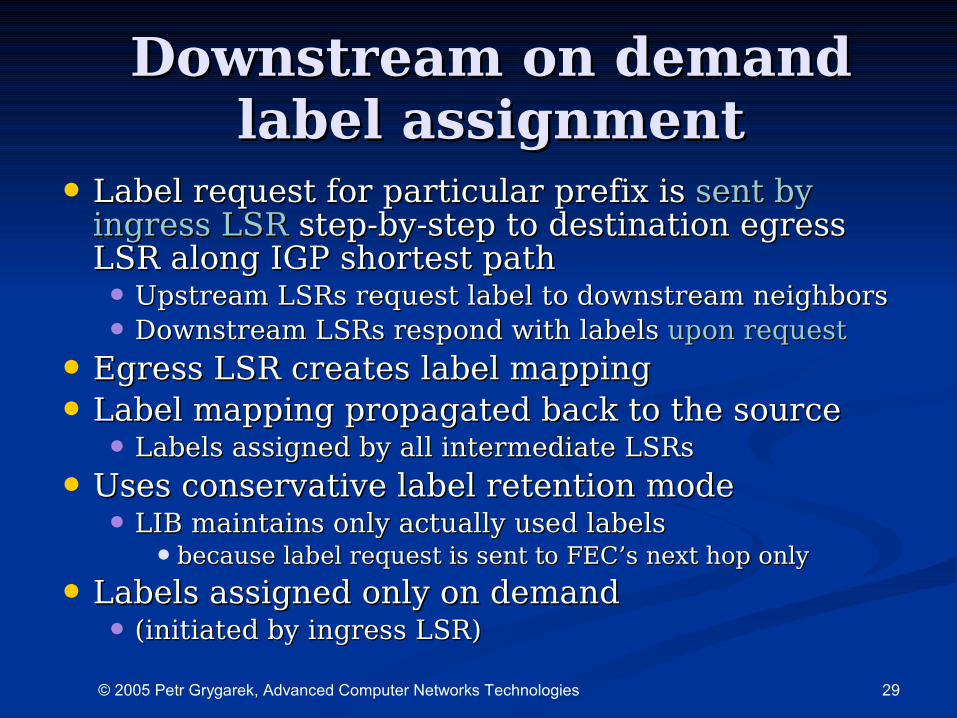
Downstream on demand Downstream on demand label assignmentlabel assignment
• Label request for particular prefix is Label request for particular prefix is sent by sent by ingress LSRingress LSR step-by-step to destination egress step-by-step to destination egress LSR along IGP shortest pathLSR along IGP shortest path• Upstream LSRs request label to downstream neighborsUpstream LSRs request label to downstream neighbors
• Downstream LSRs respond with labels Downstream LSRs respond with labels upon requestupon request
• Egress LSR creates label mappingEgress LSR creates label mapping
• Label mapping propagated back to the sourceLabel mapping propagated back to the source• Labels assigned by all intermediate LSRsLabels assigned by all intermediate LSRs
• Uses conservative label retention modeUses conservative label retention mode• LIB maintains only actually used labelsLIB maintains only actually used labels
•because label request is sent to FEC’s next hop onlybecause label request is sent to FEC’s next hop only
• Labels assigned only on demandLabels assigned only on demand• (initiated by ingress LSR)(initiated by ingress LSR)
30© 2005 Petr Grygarek, Advanced Computer Networks Technologies
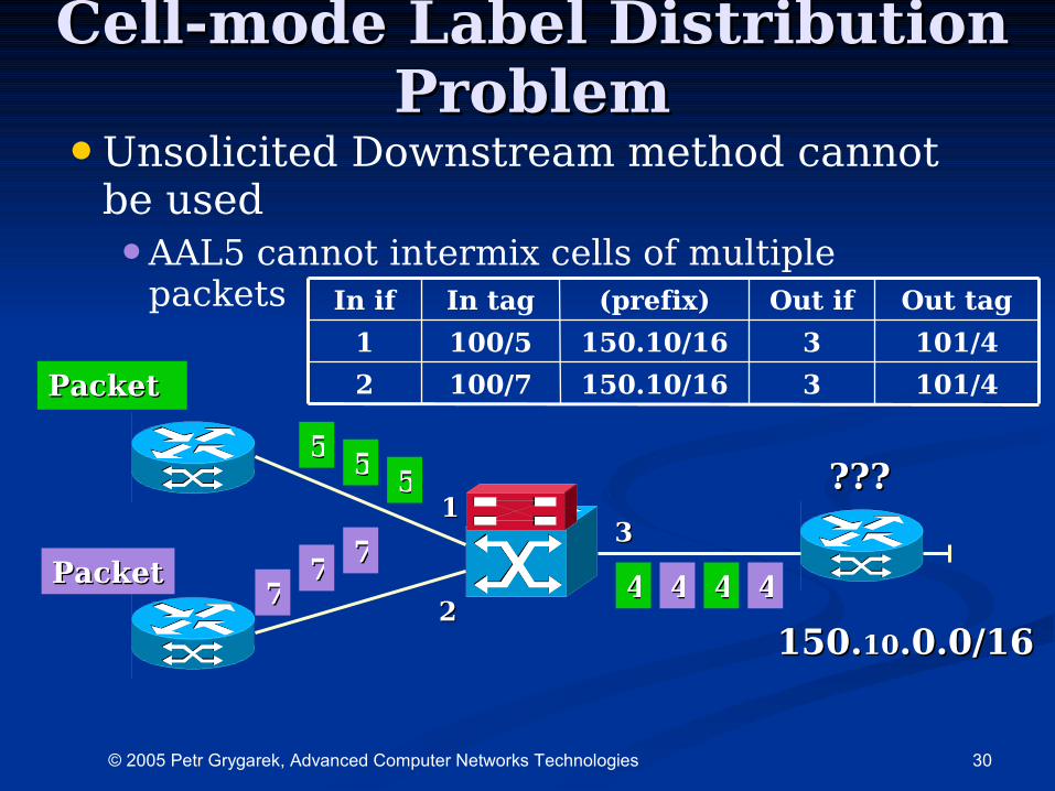
Cell-mode Label Distribution Cell-mode Label Distribution ProblemProblem
•Unsolicited Downstream method cannot be used•AAL5 cannot intermix cells of multiple
packets
101/43150.10/16100/72
101/43150.10/16100/51
Out tagOut if(prefix)In tagIn if
11
22
33
150.150.1010.0.0/16.0.0/16
PacketPacket
PacketPacket77
7777
5555
55
44 44 44 44
??????
31© 2005 Petr Grygarek, Advanced Computer Networks Technologies
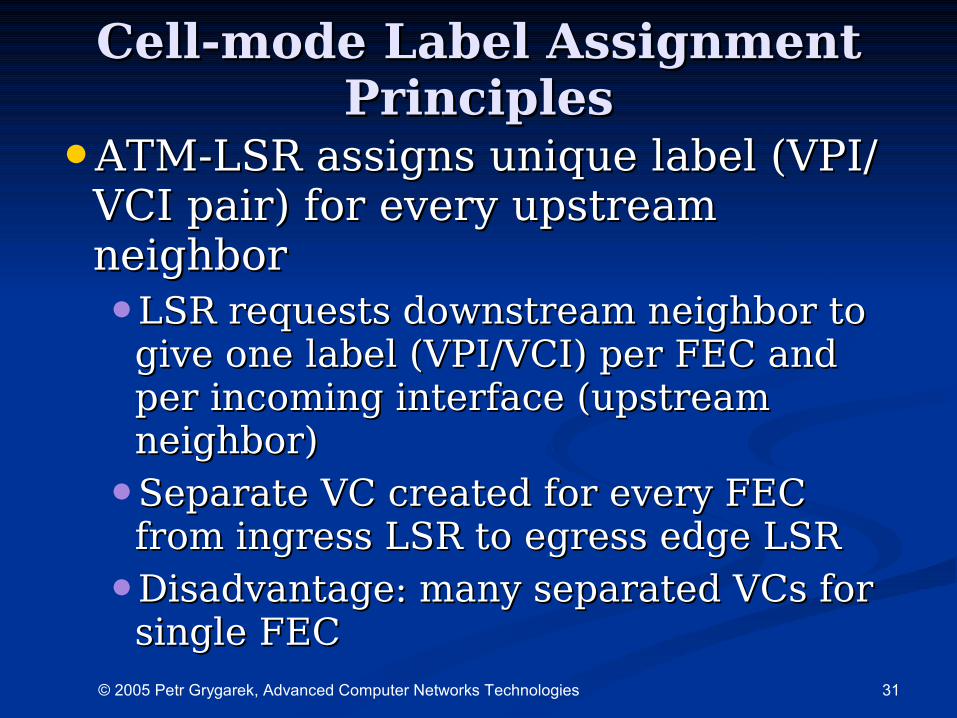
Cell-mode Label Assignment Cell-mode Label Assignment PrinciplesPrinciples
•ATM-LSR assigns unique label (VPI/ATM-LSR assigns unique label (VPI/VCI pair) for every upstream VCI pair) for every upstream neighborneighbor•LSR requests downstream neighbor to LSR requests downstream neighbor to
give one label (VPI/VCI) per FEC and give one label (VPI/VCI) per FEC and per incoming interface (upstream per incoming interface (upstream neighbor)neighbor)
•Separate VC created for every FEC Separate VC created for every FEC from ingress LSR to egress edge LSRfrom ingress LSR to egress edge LSR
•Disadvantage: many separated VCs for Disadvantage: many separated VCs for single FECsingle FEC
32© 2005 Petr Grygarek, Advanced Computer Networks Technologies
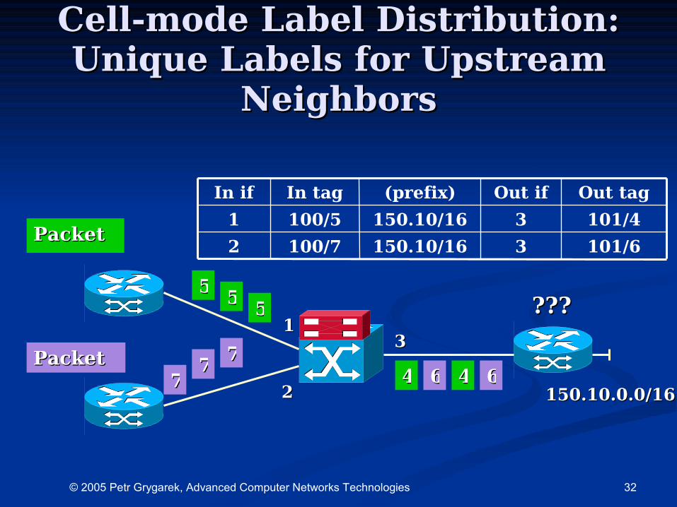
Cell-mode Label Distribution:Cell-mode Label Distribution:Unique Labels for Unique Labels for UUpstream pstream
NNeighborseighbors
101/63150.10/16100/72
101/43150.10/16100/51
Out tagOut if(prefix)In tagIn if
11
22
33
150.10.0.0/16150.10.0.0/16
PacketPacket
PacketPacket77
7777
5555
55
44 66 44 66
??????
33© 2005 Petr Grygarek, Advanced Computer Networks Technologies
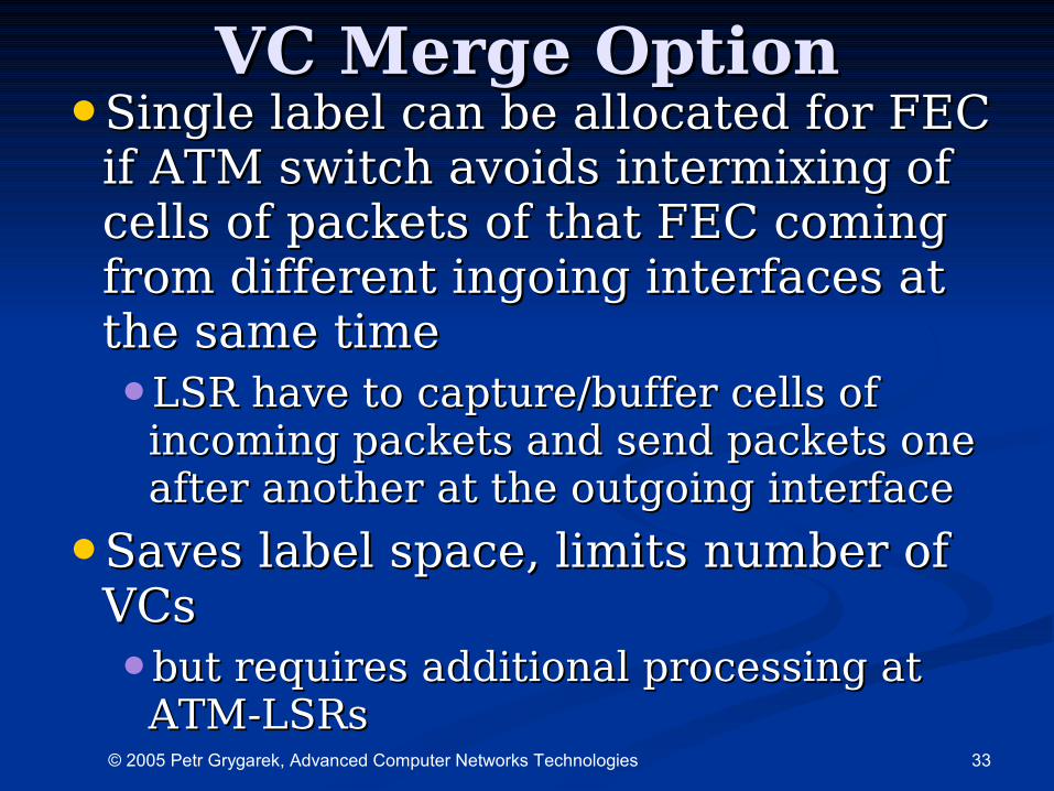
VC MergeVC Merge Option Option•Single label can be allocated for FEC Single label can be allocated for FEC
if ATM switch avoids intermixing of if ATM switch avoids intermixing of cells of packets of that FEC coming cells of packets of that FEC coming from from different different ingoing interfaces at ingoing interfaces at the same time the same time •LSR have to captureLSR have to capture/buffer/buffer cells of cells of
incoming packets and send packets one incoming packets and send packets one after another at the outgoing interfaceafter another at the outgoing interface
•Saves label space, limits number of Saves label space, limits number of VCsVCs•but requires additional processing at but requires additional processing at
ATM-LSRsATM-LSRs
34© 2005 Petr Grygarek, Advanced Computer Networks Technologies
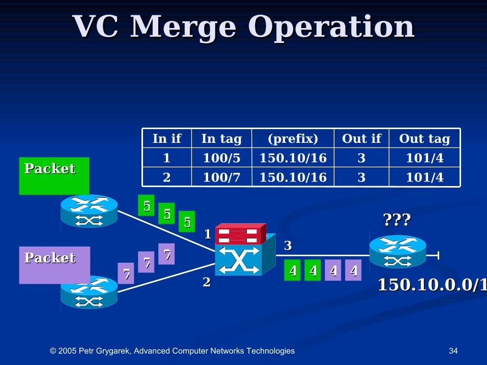
VC Merge VC Merge OOperationperation
101/43150.10/16100/72
101/43150.10/16100/51
Out tagOut if(prefix)In tagIn if
11
22
33
150.10.0.0/16150.10.0.0/16
PacketPacket
PacketPacket77
7777
5555
55
44 44 44 44
??????
35© 2005 Petr Grygarek, Advanced Computer Networks Technologies
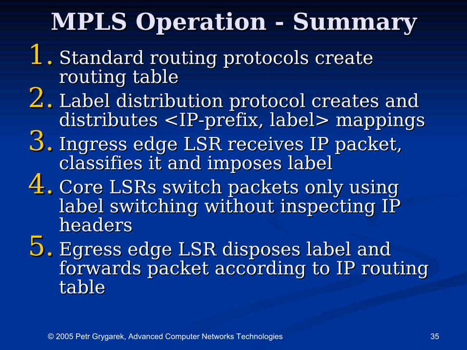
MPLS MPLS OOperation - peration - SSummaryummary
1.1. Standard routing protocols create Standard routing protocols create routing tablerouting table
2.2. Label distribution protocol creates and Label distribution protocol creates and distributes <IP-prefix, label> mappingsdistributes <IP-prefix, label> mappings
3.3. Ingress edge LSR receives IP packet, Ingress edge LSR receives IP packet, classifies it and imposes labelclassifies it and imposes label
4.4. Core LSRs switch packets only using Core LSRs switch packets only using label switching without inspecting IP label switching without inspecting IP headersheaders
5.5. Egress edge LSR disposes label and Egress edge LSR disposes label and forwards packet according to IP routing forwards packet according to IP routing tabletable
36© 2005 Petr Grygarek, Advanced Computer Networks Technologies
MPLS ApplicationsMPLS Applications
IP header and forwarding decision decoupling IP header and forwarding decision decoupling allows for better flexibility and new allows for better flexibility and new
applicationsapplications
37© 2005 Petr Grygarek, Advanced Computer Networks Technologies
Most Popular MPLS Most Popular MPLS ApplicationsApplications
•Integration of IP and ATMIntegration of IP and ATM
•MPLS Traffic engineeringMPLS Traffic engineering
•MPLS VPNMPLS VPN
38© 2005 Petr Grygarek, Advanced Computer Networks Technologies
IIntegrationntegration of of IP IP andand ATM ATM
•IP routing tightly integrated with IP routing tightly integrated with mmultipurpose ATM backbone ultipurpose ATM backbone using MPLSusing MPLS•ATM routing protocols like PNNI and ATM routing protocols like PNNI and
signalling protocols for SVCs are not signalling protocols for SVCs are not necessarynecessary
•Eliminates complex technologies to map Eliminates complex technologies to map between IP and ATM routing information between IP and ATM routing information and addressingand addressing•no need for solutions like LANE, CLIP, NHRP no need for solutions like LANE, CLIP, NHRP
and MPOA based on emulation of classical and MPOA based on emulation of classical LAN/WAN technologies over ATMLAN/WAN technologies over ATM
•ATM infrastructure may be fully utilizedATM infrastructure may be fully utilized•not as with overlay modelnot as with overlay model
39© 2005 Petr Grygarek, Advanced Computer Networks Technologies
MPLS Traffic MPLS Traffic EngineeringEngineering
40© 2005 Petr Grygarek, Advanced Computer Networks Technologies
MPLS TE GoalsMPLS TE Goals
•Minimizes network congestion, Minimizes network congestion, improve network performanceimprove network performance
•Spreads flows to multiple pathsSpreads flows to multiple paths•i.e. diverges them from “shortest” path i.e. diverges them from “shortest” path
calculated by IGPcalculated by IGP
•More efficient network resource More efficient network resource usageusage

41© 2005 Petr Grygarek, Advanced Computer Networks Technologies
MPLS TE PrincipleMPLS TE Principle
•Originating LSR sets up a TE LSP to Originating LSR sets up a TE LSP to terminating LSR through a explicitly terminating LSR through a explicitly specified pathspecified path•defined by sequence of intermediate defined by sequence of intermediate
LSRsLSRs
•either strict or loose explicit routeeither strict or loose explicit route
•LSP is calculated automatically LSP is calculated automatically using constraint-based routing or using constraint-based routing or manually using some sort of manually using some sort of management toolmanagement tool
42© 2005 Petr Grygarek, Advanced Computer Networks Technologies
MPLS-TE MechanismsMPLS-TE Mechanisms•Link information distributionLink information distribution
•Path computationPath computation
•LSP signallingLSP signalling•RSVPRSVP-TE accomplishes-TE accomplishes label assignment label assignment
during MPLS tunnel creationduring MPLS tunnel creation
•signalling not needed if path calculation signalling not needed if path calculation is performed manuallyis performed manually
•Selection of traffic that will take the Selection of traffic that will take the TE-LSPTE-LSP•by QoS class or another policy routing by QoS class or another policy routing
criteriacriteria
43© 2005 Petr Grygarek, Advanced Computer Networks Technologies
Link Information DistributionLink Information Distribution•Utilizes extensions of OSPF or IS-IS to Utilizes extensions of OSPF or IS-IS to
distribute links’ current states and distribute links’ current states and attributesattributes•OSPF LSA type 10 (opaque)OSPF LSA type 10 (opaque)
•Maximum bandwidth, reservable bandwidth, Maximum bandwidth, reservable bandwidth, available bandwidth, flags, TE metricavailable bandwidth, flags, TE metric
•Constraint-based routingConstraint-based routing•Takes into account links’ current states and Takes into account links’ current states and
attributes when calculating routesattributes when calculating routes
•““Constraint-based SPF” calculation excludes Constraint-based SPF” calculation excludes links that do not comply with required LSP links that do not comply with required LSP parametersparameters
44© 2005 Petr Grygarek, Advanced Computer Networks Technologies
LSP PreemptionLSP Preemption
•Support for creation of LSPs of different Support for creation of LSPs of different priorities with preemption optionpriorities with preemption option•setup and holding prioritysetup and holding priority
•setup priority is compared with holding priority of setup priority is compared with holding priority of existing LSPsexisting LSPs
•0 (best) – 7 (worst)0 (best) – 7 (worst)
•Preemption modesPreemption modes•Hard – just tears preempted LSP downHard – just tears preempted LSP down
•Soft – signalls pending preemption to the Soft – signalls pending preemption to the headend of existing LSP to give it opportunity headend of existing LSP to give it opportunity to reroute trafficto reroute traffic
45© 2005 Petr Grygarek, Advanced Computer Networks Technologies
LSP Path Calculation in LSP Path Calculation in Multiarea EnvironmentMultiarea Environment
•Splitting network into multiple areas Splitting network into multiple areas limits state information floodinglimits state information flooding
•Headend specifies path to route LSP Headend specifies path to route LSP setup requests using list of ABRssetup requests using list of ABRs•loose routingloose routing
•Each ABR calculates and reserves Each ABR calculates and reserves path over connected area and path over connected area and requests another ABR on the path to requests another ABR on the path to take care of next sectiontake care of next section
46© 2005 Petr Grygarek, Advanced Computer Networks Technologies
Fast RerouteFast Reroute
•In case of node or link failure, In case of node or link failure, backup LSP may be automatically backup LSP may be automatically initiated (in tens of milliseconds)initiated (in tens of milliseconds)
•Fast Reroute option must be Fast Reroute option must be requested during LSP setuprequested during LSP setup
•Global or Local restorationGlobal or Local restoration
47© 2005 Petr Grygarek, Advanced Computer Networks Technologies
Fast Reroute - Global Fast Reroute - Global restorationrestoration
•New LSP is set up by headendNew LSP is set up by headend•LSP failure is signalled to the headend LSP failure is signalled to the headend
by PathErr RSVP messageby PathErr RSVP message
•Headend has the most complete routing Headend has the most complete routing constraints information to establish a constraints information to establish a new LSPnew LSP
48© 2005 Petr Grygarek, Advanced Computer Networks Technologies
Fast Reroute - Local restorationFast Reroute - Local restoration• ““Detour” LSP around failed link/nodeDetour” LSP around failed link/node
• LSR that detected the failure (called Point of LSR that detected the failure (called Point of Local Repair) initiates new LSPLocal Repair) initiates new LSP• Detour LSPs are manually preconfigured or calculated Detour LSPs are manually preconfigured or calculated
dynamically by Point of Local Repairdynamically by Point of Local Repair
• ““Detour” joins back the original LSP at the Detour” joins back the original LSP at the Merge PointMerge Point• i.e. at Next hop for link protection, Next Next hop for i.e. at Next hop for link protection, Next Next hop for
Node protection Node protection
• Facility Backup (commonly used) - double labelling is Facility Backup (commonly used) - double labelling is used on detour pathused on detour path•external tag is dropped before packet enters Merge Pointexternal tag is dropped before packet enters Merge Point
•packets arrive to the Merge Point with the same label as packets arrive to the Merge Point with the same label as they would if they came along original LSPthey would if they came along original LSP
• One-to-One backup One-to-One backup •does not use label stackingdoes not use label stacking
•Each LSP has it’s own backup pathEach LSP has it’s own backup path
49© 2005 Petr Grygarek, Advanced Computer Networks Technologies
MPLS and DiffservMPLS and Diffserv•LSR uses the same mechanism as traditional LSR uses the same mechanism as traditional
router to implement different Per-Hop router to implement different Per-Hop Behaviors (PHBs)Behaviors (PHBs)
•2 types of LSPs (may coexist on single 2 types of LSPs (may coexist on single network):network):•EXP-inferred LSPsEXP-inferred LSPs
•can transport multiple traffic classes simultaneouslycan transport multiple traffic classes simultaneously
•EXP bits in shim header used to hold DSCP valueEXP bits in shim header used to hold DSCP value
•Map between EXP and PHB signalled during LSP setupMap between EXP and PHB signalled during LSP setup•extension of LDP and RSVP (new TLV defined)extension of LDP and RSVP (new TLV defined)
•Label-inferred LSPsLabel-inferred LSPs•can transport just one traffic classcan transport just one traffic class
•Fixed mapping of <DSCP, EXP> to PHB standardizedFixed mapping of <DSCP, EXP> to PHB standardized
50© 2005 Petr Grygarek, Advanced Computer Networks Technologies
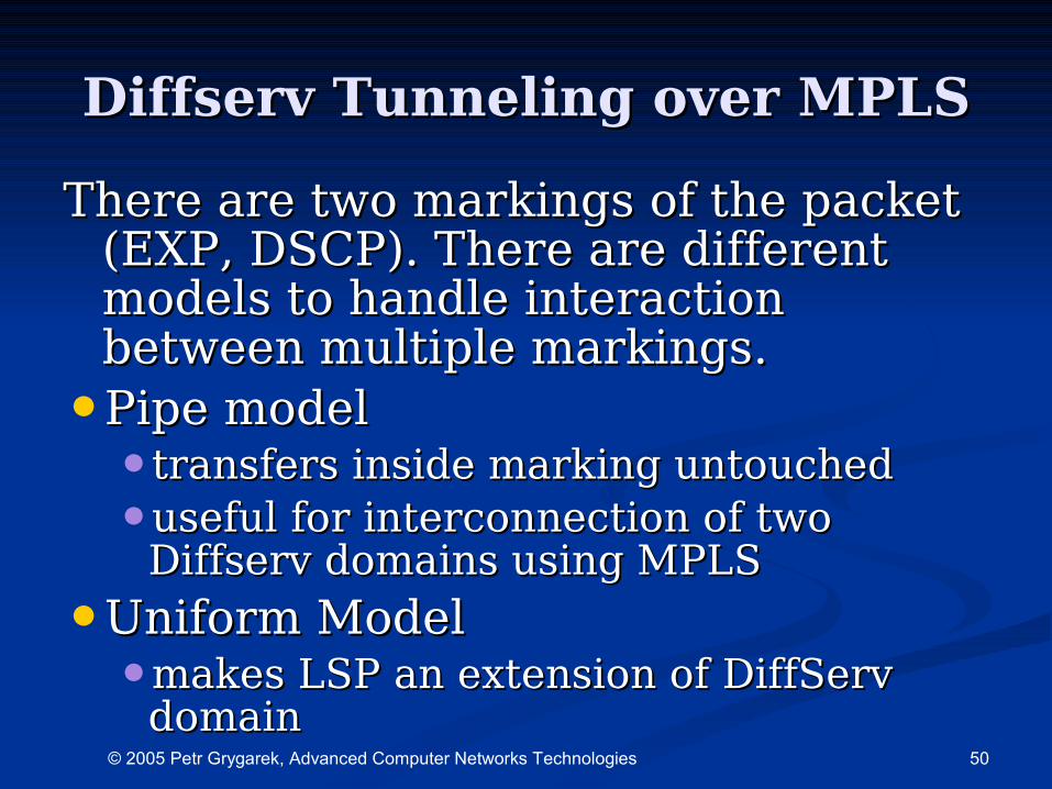
Diffserv Tunneling over MPLSDiffserv Tunneling over MPLS
There are two markings of the packet There are two markings of the packet (EXP, DSCP). There are different (EXP, DSCP). There are different models to handle interaction models to handle interaction between multiple markings.between multiple markings.
•Pipe model Pipe model •transfers inside marking untouched transfers inside marking untouched
•useful for interconnection of two useful for interconnection of two Diffserv domains using MPLSDiffserv domains using MPLS
•Uniform ModelUniform Model•makes LSP an extension of DiffServ makes LSP an extension of DiffServ
domaindomain
51© 2005 Petr Grygarek, Advanced Computer Networks Technologies
MPLS VPNsMPLS VPNs
52© 2005 Petr Grygarek, Advanced Computer Networks Technologies
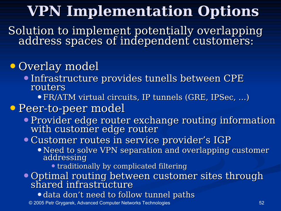
VPNVPN Implementation Options Implementation OptionsSolution to implement potentiallySolution to implement potentially overlapping overlapping
address spacesaddress spaces of independent customers: of independent customers:
•Overlay modelOverlay model•Infrastructure provides tunells between Infrastructure provides tunells between CPE CPE
routersrouters•FRFR/ATM virtual circuits, IP tunnels (GRE, IPSec, …)/ATM virtual circuits, IP tunnels (GRE, IPSec, …)
•Peer-to-peer modelPeer-to-peer model•Provider edge router exchange routing information Provider edge router exchange routing information
with customer edge routerwith customer edge router•Customer routes in service provider’s IGPCustomer routes in service provider’s IGP
•Need to solve VPN separation and overlapping customer Need to solve VPN separation and overlapping customer addressingaddressing• traditionally by complicated filteringtraditionally by complicated filtering
•Optimal routing between customer sites through Optimal routing between customer sites through shared infrastructureshared infrastructure•data don’t need to follow tunnel pathsdata don’t need to follow tunnel paths
53© 2005 Petr Grygarek, Advanced Computer Networks Technologies
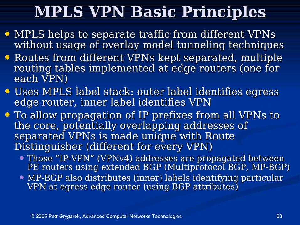
MPLS VPN Basic PrinciplesMPLS VPN Basic Principles
• MPLS helps to separate traffic from different VPNs MPLS helps to separate traffic from different VPNs without usage of overlay model tunneling techniques without usage of overlay model tunneling techniques
• Routes from different VPNs kept separated, multiple Routes from different VPNs kept separated, multiple routing tables implemented at edge routers (one for routing tables implemented at edge routers (one for each VPN)each VPN)
• Uses MPLS label stack: outer label identifies egress Uses MPLS label stack: outer label identifies egress edge router, inner label identifies VPNedge router, inner label identifies VPN
• To allow propagation of IP prefixes from all VPNs to To allow propagation of IP prefixes from all VPNs to the core, potentially overlapping addresses of the core, potentially overlapping addresses of separated VPNs is made unique with Route separated VPNs is made unique with Route Distinguisher (different for every VPN)Distinguisher (different for every VPN)• Those “IP-VPN” (VPNv4) addresses are propagated between Those “IP-VPN” (VPNv4) addresses are propagated between
PE routers using extended BGP (Multiprotocol BGP, MP-BGP)PE routers using extended BGP (Multiprotocol BGP, MP-BGP)
• MP-BGP also distributes (inner) labels identifying particular MP-BGP also distributes (inner) labels identifying particular VPN at egress edge router (using BGP attributes)VPN at egress edge router (using BGP attributes)
54© 2005 Petr Grygarek, Advanced Computer Networks Technologies
MPLS VPN advantagesMPLS VPN advantages
•Integrates advantages of overlay and Integrates advantages of overlay and peer-to-peer modelpeer-to-peer model•Overlay model advantages:Overlay model advantages:
•security and customer isolationsecurity and customer isolation
•Peer-to-peer model advantages:Peer-to-peer model advantages:•routing optimalityrouting optimality
•Simplicity of new CPEs additionSimplicity of new CPEs addition
55© 2005 Petr Grygarek, Advanced Computer Networks Technologies
MPLS VPN ImplementationMPLS VPN Implementation• VPN defined as set of sites sharing the same VPN defined as set of sites sharing the same
routing informationrouting information• Site may belong to multiple VPNsSite may belong to multiple VPNs
• Multiple sites (from different VPNs) may be Multiple sites (from different VPNs) may be connected to the same PE routerconnected to the same PE router
• PE routers maintains only routes for connected PE routers maintains only routes for connected VPNs and backbone routes needed to reach VPNs and backbone routes needed to reach other PEsother PEs• Increases scalabilityIncreases scalability• Decreases performance requirements of PE routerDecreases performance requirements of PE router
• PE router uses IP at customer network PE router uses IP at customer network interface(s) and MPLS at backbone interfacesinterface(s) and MPLS at backbone interfaces
• Backbone uses only label switchingBackbone uses only label switching• IGP routing protocol used only to establish optimal IGP routing protocol used only to establish optimal
label switch pathslabel switch paths
• Utilizes MPLS label stackUtilizes MPLS label stack• Inner label identifies VPNInner label identifies VPN• Outer label identifies egress LSROuter label identifies egress LSR
56© 2005 Petr Grygarek, Advanced Computer Networks Technologies
Routing information Routing information exchangeexchange
•P-P and P-PE routers P-P and P-PE routers •Using IGPUsing IGP
•Needed to determine paths between Needed to determine paths between PEs over MPLS backbonePEs over MPLS backbone
•PE-PE routers (non-adjacent)PE-PE routers (non-adjacent)•Using MP-iBGP sessionsUsing MP-iBGP sessions
•Needed to exchange routing Needed to exchange routing information between routing tables for information between routing tables for particular VPN (VRFs)particular VPN (VRFs)•commonly between VRFs of the same VPNcommonly between VRFs of the same VPN
57© 2005 Petr Grygarek, Advanced Computer Networks Technologies
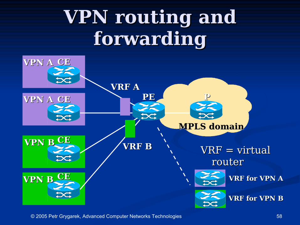
Routing information in PE Routing information in PE routersrouters
PE routers maintain multiple separated PE routers maintain multiple separated routing tablesrouting tables
•Global routing table – filled with Global routing table – filled with backbone routes (from IGP)backbone routes (from IGP)•allows to reach other PE routersallows to reach other PE routers
•VRF (VPN routing & forwarding)VRF (VPN routing & forwarding)•Separate routing tables for individual VPNsSeparate routing tables for individual VPNs
•Every router interface assigned to a single Every router interface assigned to a single VRFVRF
•VRF instance can be seen as virtual routerVRF instance can be seen as virtual router
58© 2005 Petr Grygarek, Advanced Computer Networks Technologies
VPN routing and VPN routing and forwardingforwarding
VRF = virtual VRF = virtual routerrouter
CECE
CECE PEPE
CECE
PP
VPN AVPN A
VPN AVPN A
VPN BVPN B
VRF AVRF A
VRF BVRF B
VPN BVPN B
VRF for VPN BVRF for VPN B
VRF for VPN AVRF for VPN ACECE
MPLS domainMPLS domain
59© 2005 Petr Grygarek, Advanced Computer Networks Technologies
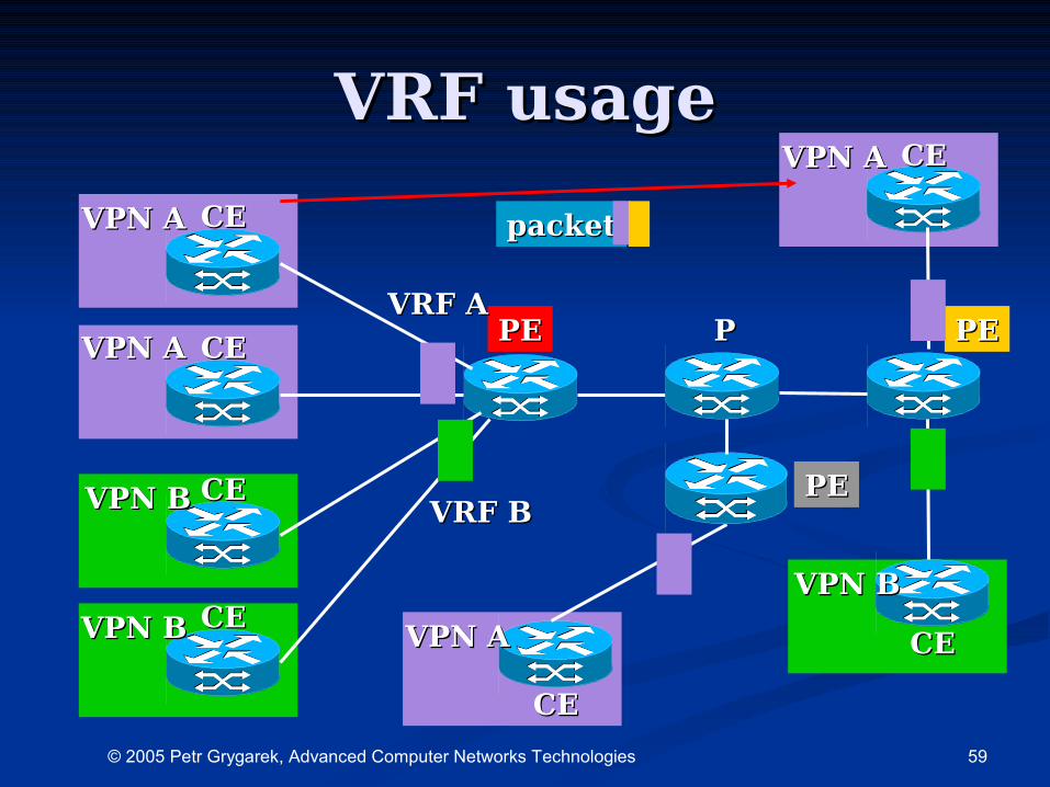
VRF usageVRF usage
CECE
CECE PEPE
CECE
PP
VPN AVPN A
VPN AVPN A
VPN BVPN B
VRF AVRF A
VRF BVRF B
VPN BVPN B
PEPE
CECE
CECE
VPN AVPN A
VPN BVPN BCECE
CECE
VPN AVPN A
PEPE
packetpacket
60© 2005 Petr Grygarek, Advanced Computer Networks Technologies
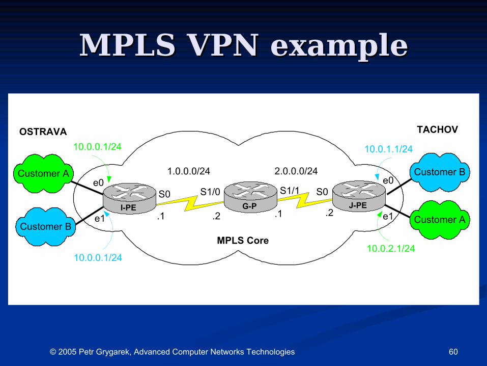
MPLS VPN exampleMPLS VPN example
10.0.0.1/24
S0I-PE
Customer A
G-P
S0S1/0 S1/1e0 e0
e1 e1
10.0.0.1/24
Customer A Customer B
Customer B
J-PE
10.0.1.1/24
10.0.2.1/24
1.0.0.0/24 2.0.0.0/24
.1.1 .2 .2
OSTRAVA TACHOV
MPLS Core
61© 2005 Petr Grygarek, Advanced Computer Networks Technologies
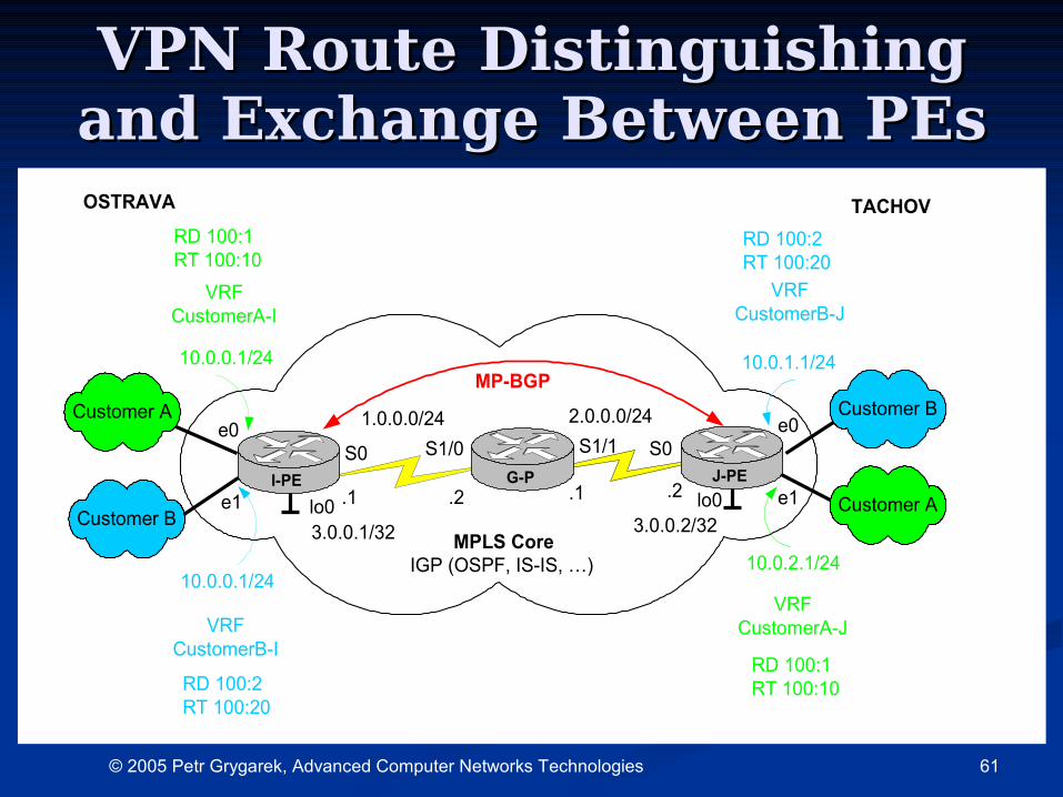
VPN Route Distinguishing VPN Route Distinguishing and Exchange Between PEsand Exchange Between PEs
10.0.0.1/24
S0I-PE
Customer A
G-P
S0S1/0 S1/1e0 e0
e1 e1
10.0.0.1/24
Customer A Customer B
Customer B
J-PE
10.0.1.1/24
10.0.2.1/24
1.0.0.0/24 2.0.0.0/24
.1.1 .2 .2lo0 lo0
3.0.0.1/32 3.0.0.2/32
VRFCustomerA-I
VRFCustomerA-JVRF
CustomerB-I
VRFCustomerB-J
RD 100:2RT 100:20
RD 100:2RT 100:20
RD 100:1RT 100:10
RD 100:1RT 100:10
OSTRAVA TACHOV
MPLS CoreIGP (OSPF, IS-IS, …)
MP-BGP
62© 2005 Petr Grygarek, Advanced Computer Networks Technologies
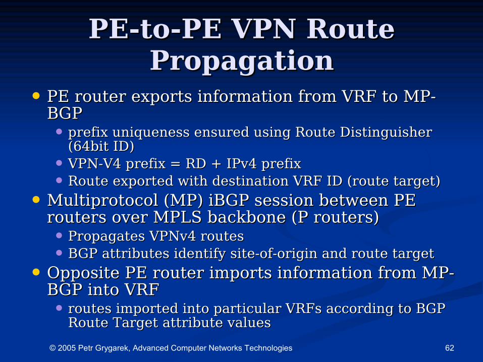
PEPE--toto--PE PE VPN Route VPN Route PropagationPropagation
• PE router exports information from VRF to MP-PE router exports information from VRF to MP-BGPBGP• prefix uniqueness ensured using Route Distinguisher prefix uniqueness ensured using Route Distinguisher
(64bit ID)(64bit ID)
• VPN-V4 prefix = RD VPN-V4 prefix = RD + IPv4 prefix+ IPv4 prefix
• Route exported with destination VRF ID (route target)Route exported with destination VRF ID (route target)
• MMultiprotocol (Multiprotocol (MPP) i) iBGP session between PE BGP session between PE routersrouters over MPLS backbone (P routers) over MPLS backbone (P routers)• Propagates VPNv4 routesPropagates VPNv4 routes
• BGP attributes identify site-of-origin and route targetBGP attributes identify site-of-origin and route target
• Opposite Opposite PE router imports information from MP-PE router imports information from MP-BGP into VRFBGP into VRF• routes imported into particular VRFs according to BGP routes imported into particular VRFs according to BGP
Route Target attribute valuesRoute Target attribute values
63© 2005 Petr Grygarek, Advanced Computer Networks Technologies
MPLS VPN BGP MPLS VPN BGP attributesattributes
•Site of Origin (SOO)Site of Origin (SOO)•Identifies site where the route Identifies site where the route
originated fromoriginated from•avoids loopsavoids loops
•Route TargetRoute Target•Controls where the route should be Controls where the route should be
exported toexported to•i.e. to which VRFi.e. to which VRF
64© 2005 Petr Grygarek, Advanced Computer Networks Technologies
Customer route advertisement Customer route advertisement from PE router (MP-BGP)from PE router (MP-BGP)
•PE router assigns RT, RD based on PE router assigns RT, RD based on source VRF and SOOsource VRF and SOO
•PE router assigns VPN (MPLS) labelPE router assigns VPN (MPLS) label•Identifies particular VRF (VPN site’s Identifies particular VRF (VPN site’s
routing table)routing table)
•Used as second label in the label stackUsed as second label in the label stack•Top-of-stack label identify egress PE routerTop-of-stack label identify egress PE router
•Route’s next-hop rewritten to Route’s next-hop rewritten to advertising PE router loopback interfaceadvertising PE router loopback interface
•MP-iBGP update sent to other PE MP-iBGP update sent to other PE routersrouters
65© 2005 Petr Grygarek, Advanced Computer Networks Technologies
CECE to to PEPE routing information routing information exchangeexchange
•CE router always exchanges routes with CE router always exchanges routes with VRF assigned to interface connecting VRF assigned to interface connecting that CE routerthat CE router•IGP (RIPv2,OSPF)IGP (RIPv2,OSPF)
•External BGPExternal BGP
•Static routing or directStatic routing or directlly connected y connected networksnetworks
•Multiple Multiple instances of instances of routing process routing process ((for every VRFfor every VRF) are running on PE ) are running on PE routerrouter•or separated routing contexts in single or separated routing contexts in single
routing routing processprocess
66© 2005 Petr Grygarek, Advanced Computer Networks Technologies
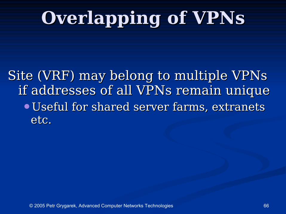
Overlapping of VPNsOverlapping of VPNs
Site (VRF) may belong Site (VRF) may belong to multiple to multiple VPNs VPNs if addresses of all VPNs remain uniqueif addresses of all VPNs remain unique•Useful for shared server farms, extranets Useful for shared server farms, extranets
etc.etc.
67© 2005 Petr Grygarek, Advanced Computer Networks Technologies
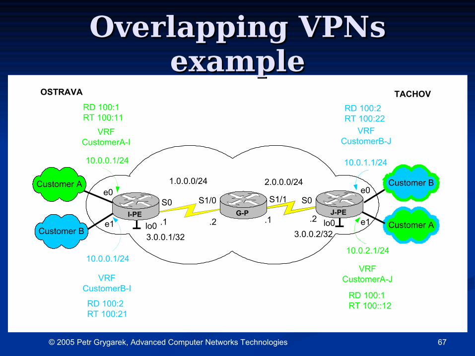
Overlapping VPNs Overlapping VPNs exampleexample
10.0.0.1/24
S0I-PE
Customer A
G-P
S0S1/0 S1/1e0 e0
e1 e1
10.0.0.1/24
Customer A Customer B
Customer B
J-PE
10.0.1.1/24
10.0.2.1/24
1.0.0.0/24 2.0.0.0/24
.1.1 .2 .2lo0 lo0
3.0.0.1/32 3.0.0.2/32
VRFCustomerA-I
VRFCustomerA-JVRF
CustomerB-I
VRFCustomerB-J
RD 100:2RT 100:21
RD 100:2RT 100:22
RD 100:1RT 100:11
RD 100:1RT 100::12
OSTRAVA TACHOV


![[MPLS Configuration Guide] - D-Link Academyacademy.dlink.com/temp/exam_Issue/230/MPLS Configuration Guide… · MPLS Configuration Guide Multiprotocol Label Switching (MPLS) MPLS](https://img.pdfslide.net/doc/110x75/5a815ac47f8b9ada388cfeea/mpls-configuration-guide-d-link-configuration-guidempls-configuration-guide.jpg)