Embed Size (px)
Citation preview

INSTRUCTION MANUAL
NF-308 Multipurpose LCD Display Cable Test & Inspection Instrument
Please read and learn safety instructions before use or maintain the equipment
●The tester uses 9V battery for power supply .
●Never put the equipment in the place with much dust, humidity and
high temperature (over 40℃).
●Please use battery according to the specif ication; otherwise, it
may result in damage to equipment.
●Please never dismount the equipment arbitrari ly. The maintenance
and care shall be conducted by professional personnel.
● The tester will shut off automatically i f i t does not work for 30
minutes in succession.
●Please take out the battery in launcher and receiver if the
equipment is not used for a long time so as to prevent that the
battery l iquid is leaked in future.
●Never use the equipment to detect power cord with electricity
(such as power supply circuit of 220V), other wise, it may result in
damage to equipment and personal injury.
●Never conduct related operation of communication l ine in
thunderstorm weather so as to prevent l ightning stroke and
impact on personal safety.

Overview..............................................................1
Main Functions and features................................2
Technical index ....................................................2
Product interface and keypad Introduction...........4
Product operation methods..................................5
Start up or shut down AF hunting function...........11
Diagram of series products................................12
Contents
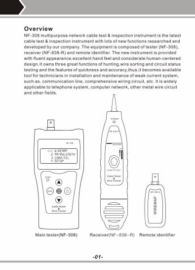
Main tester(NF-308) Receiver(NF-838-R) Remote identifier
-01-
OverviewNF-308 multipurpose network cable test & inspection instrument is the latest
cable test & inspection instrument with lots of new functions researched and
developed by our company. The equipment is composed of tester (NF-308),
receiver (NF-838-R) and remote identifier. The new instrument is provided
with fluent appearance,excellent hand feel and considerate human-centered
design.It owns three great functions of hunting,wire sorting and circuit status
testing and the features of quickness and accuracy,thus,it becomes available
tool for technicians in installation and maintenance of weak current system,
such as, communication line, comprehensive wiring circuit, etc. It is widely
applicable to telephone system, computer network, other metal wire circuit
and other fields.
NF-308
1.wiremap
2.pair&length3.coax/tel 4.setup
WIR
EM
AP
NF-308-S
PUSH TO TEST
Cable Tester
Wire Tracker&
RECEIVER
POWER
NF-838-R
VOL
PAIR&L
Cable Tester
Wire Tracker&
SCAN
PUSH

Main Functions and featuresOne person enough to complete cable continuity check.
Directly hunt 5E, 6E, telephone wire, coaxial cable, USB cable and other
cables.
Check wiring error in 5E, 6E, telephone line, coaxial cable, USB cable
and such as open circuit, short circuit, jumper wire, reverse connection
or cross-talk interference.
Locate the wiring or connection error.
Measure cable length and determine the distance of open circuit and
short circuit.
Dynamically calibrate cable length and make length measurement as
accurate as 97%.
Simple and easy use. Big screen to display test result clear.
Portable unit with long battery life (wait-case 50 hours).
Automatically time-delay shut off and backlight display function.
Measure length and pair with or without far-end recognizer.
Locate cable and there are 8 far-end passive test jacks (ID No.ID1-ID 8).
Far-end recognizer with prompting voice.
Self-checking function and automatically compensate any change in
battery capacity or ambient temperature.
Single board computer software watchdog design and reliable operation.
●
●
●
●
●
●
●
●
●
●
●
●
●
●
Technical indexes
Overall dimension
Main tester: 185×105×50mm; receiver: 218×46×29mm;
Remote identifier: 84×34×27mm.
Power Two laminated batteries of 9V.
DisplaySpecial 4 x 16 character big screen LCD lattice
(valid visual field 61.6 x 25.2 mm).
Type of cable testedSTP/UTP twin twisted cable, coaxial cable, telephone line.
(1).
(2).
(3).
(4).
-02-

(5).
(6).
(7).
(8).
(9).
(10).
(11).
(12).
Type of cable detected
5E, 6E, telephone wire, coaxial cable, USB cable and other metal wires.
Ambient temperature in work
-10℃~+60℃
Tester Port
Tester RJ45 master port (M), tester LOOPBACK RJ45 port (L),
hunting RJ45 port(With RJ45);
Remote identifier RJ45 port (R)
The extra BNC and RJ11 converters are used to measure and
check the continuity of coaxial cable and telephone line.
Length Measurement of Twin Twisted Cable
Scope: 1~350 M ( 3 ~200 ft)
Calibration accuracy: 3% (+/- 0.5M or +/- 1.5 ft)(calibrating cable > 5 M)
Shipment accuracy: 5% (+/- 0.5 M or +/- 1.5 ft).(AMP, AT&T Class 5 cable)
Display: M or ft.
Length Calibration:
User can set calibration factor by himself with a given length cable.
The length of calibrating cable is more than 5 M.
Wire Sequence and Locating Cable Error:
Check errors such as open circuit, short circuit, reverse connection,
cross-over or cross-talk interference.
Locating Cable
8 Remote identifier test jacks (ID 1≥ID 8).
Automatic Time-delay Shut Off Time:
The tester does not operate for 30 minutes.
-03-
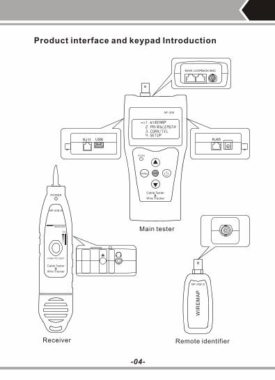
Product interface and keypad Introduction
-04-
Main tester
Receiver Remote identifier
NF-308
1.wiremap
2.pair&length3.coax/tel 4.setup
PAIR&L
Cable Tester
Wire Tracker&
SCAN
PUSH
WIR
EM
AP
NF-308-S
PUSH TO TEST
Cable Tester
Wire Tracker&
RECEIVER
POWER
NF-838-R
VOL
MAIN LOOPBACK BNC
RJ45RJ11 USB

NetWork
Cable Tester
1.wiremap
2.pair&length3.coax/tel 4.setup
Product operation methodsStart and display:
Carry out self-checking at the same time (The dotted line dynamically displays
the course of self-checking from left to right):
5 seconds or push any arbitrary key to display main menu.
Main menu display:
PAIR&L
Wiring diagram (WIREMAP) test function:After entering the wiring diagram (WIREMAP) test function, the tester shall
carry out wiring diagram (WIREMAP) test and displays as follows while
checking is being undertaken:
----Testing ----
-05-
There are four functions to be chosen on main menu.1. WireMap --- Wiring diagram measurement to check end-to-end con-tinuity
of cables M, L, R and locate error.
2. Pair & Length ---Pair and measure length to verify cable length,open circuit
distance, pairing and cross-talk interference.
3. Coax/Tel --- Coaxial cable and telephone line measurement to check
continuity and indicate open circuit and short circuit.
4. SETUP---Calibrate and set up the tester (Refer to description hereinafter).
With main menu display, push key to move cursor indicator up
and down to desired item and then push key to enterrelated test
function accordingly.
“->”
12345678...

Test Result 1: Short circuit (SHORT)It displays as follows if there is any short circuit in cable or terminal: (e.g.12 short circuit in the sample)
Short:
12
At the moment, push key to restart testing or push key to return main
menu.Always correct short circuit error first and then start further measurement.
Test Result 2: Neither far-end matcher (ID) is foundnor cable inserts
local port (L).The tester will automatically detect far-end matcher (ID) or local port (L) cable and it will display as follows if the far-end of cable to be checked does not insert into the far-end matcher (ID) or if the cable does not into the local(L)in local test:
No adapter:
At the moment, push key to restart testing or push key toreturn main menu.
Test Result 3: Normal wiring diagram (WIREMAP) displayThe tester will automatically detect far-end matcher (ID) or local port (L)cable and it will display wiring diagram (WIREMAP) as follows if it is found the far-end matcher (ID) or the local port (L) on the far-end of cable to be checked:
Wire map:pass
R: 12345678 id1
Iiiiiiii M: 12345678
"R:" line shows RJ45 jack pin number of far-end port and "ID1"is the remote identifier number." |" line shows the connecting line between far-end port and master port.
"M:" line shows the RJ45 jack pin number of master port.At the moment, push key to restart testing or push key to return main menu.
-06-
PAIR&L
PAIR&L
PAIR&L

Test Result 4: Wiring diagram (WIREMAP) displaywhen there is an open circuit at the far-end of cable.
Wire map:fail
R: 12 x45 x78 id1
Iiiiiiii
M: 12345678
"R:" line "3" and "6" pins location display "x", it indicates an open circuit infar-end plug "3" and "6" pins and the open circuit is located nearby the far-end plug.(The open circuit should be located within 10% cable length if it is measured from the far-end plug)Note: If you use far-end matcher (ID) to measure wiring diagram(WIREMAP), because the test is made via the paired two cable cores,the open circuit at the far-end always displays in pair as shown above where there is one open circuit or all are open circuits in the far-end"3"and "6"pins. For identification, it is simple to move the tester to the far-end to have the measurement.
Test Result 5: Wiring diagram (WIREMAP) display when there is an open
circuit at the near-end of cable. It will display wiring diagram (WIREMAP) as follows if there is an open circuit at the near-end plug of the cable:
Wire map:fail
R: 12345678 id1
Iiiiiiii M: 12 x45678
"M:" line "3" pin location displays "x", it indicates an open circuit at near-end plug "3" pin and the open circuit is located nearby the near-end plug.(The open circuit should be located within 10% cable length if it is measured from the near-end plug)
Test Result 6: Wiring diagram (WIREMAP) display when there is an open
circuit in the middle of the cable.It will display wiring diagram (WIREMAP) as follows if there is an opencircuit in the middle of the cable:
Wire map:fail
R: 12345678 id1
Iixiiiii M: 12345678
"|" line "3" pin location displays "x", it indicates an open circuit in the middle of "3" pin cable. (The open circuit should be located within 10%-90%cable length if it is measured from the near-end plug.) For further locating open circuit, the pair and length function (PAIR & LENGTH) of the tester could used as detailed hereinafter.
-07-

Pair and length measurement (PAIR & LENGTH) function:No matter whether there is a far-end recognizer (ID) at the far-end of the cable, the tester is capable to have pair and length (PAIR & LENGTH)measurement. Therefore, the far-end recognizer (ID) can keep connected in the course of wiring diagram (WIREMAP) and pair and length (PAIR&LENGTH) measurement to avoid repeated insertion and pulling out.After entering into pair and length (PAIR & LENGTH) measurement function, the tester shall have pair and length (PAIR & LENGTH) test and it will display as follows to indicate the measurement is being undertaken:
----Testing ----12345678...
Note:In view of different technical parameters in various brand cables, the user should apply the tester dynamic calibration function before length measurement (Refer to the details herein).
Test Result 1: Short circuit (SHORT)It will display as follows if there is any short circuit in cable or terminal:(12 short circuit in the sample)
Short:
12
(The tester is incapable to know the exact location of short circuit.)At the moment, push key to restart test or push key to return the main menu.Always correct short circuit error first and then start further measurement.
Test Result 2: Normal pair and length (PAIR &LENGTH) display
P a i r 12 100.0m
P a i r 78 99.8m
P a i r 36 100.3m
P a i r 45 100.2m
In which, the figure (e.g. 12) after the pair is the pair line number and itis the length after the line number.At the moment, push key to restart test or push key toreturn the main menu.
-08-
PAIR&L
It will display as follows if pair and length(PAIR & LENGTH) measurement is in normal condition:
PAIR&L

Test Result 3: Abnormal pair and length (PAIR &LENGTH) displayIt will display the paired lines first if there is unpaired lines in the pair andlength (PAIR & LENGTH) measurement:
P a i r 12 100.0m
78
P a i r 36 100.3m
P a i r 45 100.2m
In which, the last line (78 ) icates there is no pair is found in lines 7and 8, at the moment, it will display the length of unpaired line number(as shown below): if you push the key: ( Or push PAIR&L key to return the main menu)
It will display " X " to indicate an open circuit if the length is less than 90% of other line pair length and the open circuit is located at around 89.3M from the tester. (The open circuit line number could be rechecked by WIREMAP function.)At the moment, push key to go back previous picture and push key to show further unpaired line number length.(Or push key to return the main menu)
P i n 7 100.0m
P i n 8 89.3m x
Coaxial cable and telephone line measurement function:After entering into coaxial cable and telephone line measurement (Coax/Tel) function, the tester shall have test and show the test result as follows:
Coax/tel test
Pass
It shall display OPEN if there is any open circuit or the coaxial cable and telephone line is not connected.It shall display SHORT if there is any short circuit.At the moment,push key to repeat the measurement or push key to return the main menu. The far-end recognizer will have beep prompt sound if the connection is in normal condition.
“ ”“ ”
Note: For coaxial cable measurement, it needs accessories: two (2) BNC matchers. One is used to connect M port RJ45 and the cable to be checked and the another is used to connect the far-end matcher R port and the cable to be checked.For telephone line measurement,it needs accessories:two(2)RJ11 matchers.One is used to connect M port RJ45 and the cable to be checked and the another is used to connect the far-end matcher R port and the cable to be checked.
-09-
PAIR&L
PAIR&L
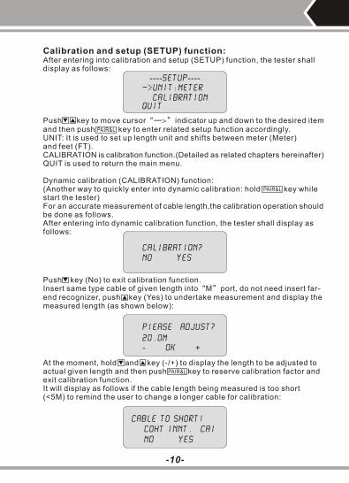
Calibration and setup (SETUP) function:After entering into calibration and setup (SETUP) function, the tester shall display as follows:
----setup ----Unit:meter
Calibration Quit
Push key to move cursor indicator up and down to the desired item and then push key to enter related setup function accordingly.UNIT: It is used to set up length unit and shifts between meter (Meter)and feet (FT).CALIBRATION is calibration function.(Detailed as related chapters hereinafter)QUIT is used to return the main menu.
“—>”
Dynamic calibration (CALIBRATION) function:(Another way to quickly enter into dynamic calibration: hold key while start the tester)For an accurate measurement of cable length,the calibration operation should be done as follows.After entering into dynamic calibration function, the tester shall display as follows:
CALIBRATION?
NO YES
Push key (No) to exit calibration function.Insert same type cable of given length into M port, do not need insert far-end recognizer, push key (Yes) to undertake measurement and display the measured length (as shown below):
“ ”
Piease adjust?
20.0m
- ok +
At the moment, hold and key (-/+) to display the length to be adjusted to actual given length and then push key to reserve calibration factor and exit calibration function.It will display as follows if the cable length being measured is too short(<5M) to remind the user to change a longer cable for calibration:
Cable to short!
coht innt. cai
No yes
-10-
PAIR&L
PAIR&L
PAIR&L
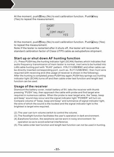
Short
12
Continue? No yes
At the moment, push key (No) to exit calibration function. Push key (Yes) to repeat the measurement.Note:If the tester is restarted after it shuts off, the tester will recoverthe standard calibration factor of Class UTP5 cable as setupbefore shipment.
Start up or shut down AF hunting function(1). Press PUSH key,the hunting indicator light (SCAN) flashes,which indicates that audio frequency transmission of main tester is normal, inert wire to be hunted into LAN cable hunting port with “RJ45” pattern. If RJ11/USB/BNC and other cable can be directly inserted corresponding port, such as, RJ11/USB/BNC; then hunt wire required with receiving end (the usage of receiver is shown in the following). After the hunting is completed,press PUSH key again,PUSH key springs out,hunting indicator light (SCAN) turns off and then cable order test function and length test function can be used.
-11-
(2).The user can turn volume switch to control the volume.
(3).The floodlight function facilitates the user's operation in dark environment.
(4).Earphone function, the earphone can be worn in noisy environment for
operation so as to avoid external interference.
(5).The cable order test function and length test function can not be used in hunting.
Usage of the receiver Dismount the battery cover, install battery of 9V, take the receiver with thumb pressing “PUSH” key, then approach the cable with probe and find target wire required in numerous cables. When the probe is near target wire, the “beep, beep and beep” sound may occur and the signal indicator light “POWER” will turn on. Compare volume of “beep, beep and beep” and luminance of signal indicator light, the wire of which the sound is the loudest and the signal indicator light is the brightest is target wire required.
At the moment, push key (No) to exit calibration function. Push key(Yes) to repeat the measurement.

-12-
Diagram of series products
NF-308
NF-801RNF-806B
NF-838
NF-866
NF-902 NF-906A NF-3468
NF-8208