Embed Size (px)
Citation preview
Multiservice Switch Architecture
Scope
• Discuss only distributed architecture
• Focus on data path functions

Outline
• Architecture Overview
• Data Path Processing– Data path functions– Fast or slow path processing
• Control and Data Plane partitioning
• High Availability
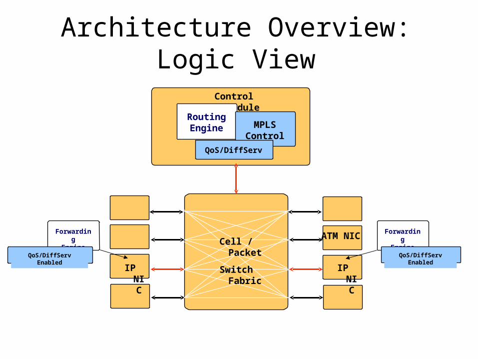
Architecture Overview: Logic View
IP NIC IP NIC
Control Module
Cell / Packet
Switch Fabric
RoutingEngine
ForwardingEngine
ForwardingEngine
MPLSControl
QoS/DiffServ
QoS/DiffServ EnabledQoS/DiffServ Enabled
ATM NIC
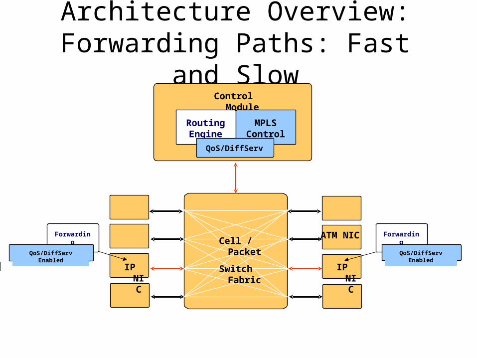
Architecture Overview: Forwarding Paths: Fast and Slow
IP NIC IP NIC
Control Module
Cell / Packet
Switch Fabric
RoutingEngine
ForwardingEngine
ForwardingEngine
MPLSControl
QoS/DiffServ
QoS/DiffServ EnabledQoS/DiffServ Enabled
ATM NIC

Architecture Overview: Interfaces
Source: Agilent Technologies
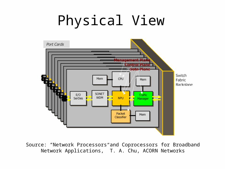
Physical View
Source: “Network Processors and Coprocessors for Broadband Network Applications,” T. A. Chu, ACORN Networks

Card Level Paths: Fast and Slow
Source: “Network Processors and Coprocessors for Broadband Network Applications,” T. A. Chu, ACORN Networks
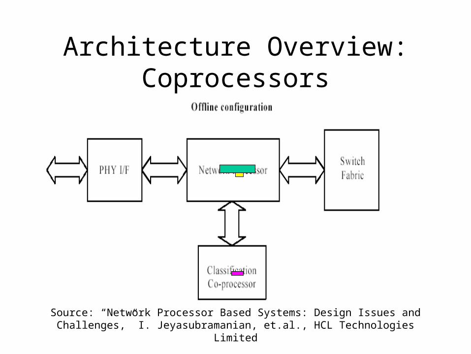
Architecture Overview: Coprocessors
Source: “Network Processor Based Systems: Design Issues and Challenges,” I. Jeyasubramanian, et.al., HCL Technologies Limited

Architecture Overview: Coprocessors
Source: “Network Processor Based Systems: Design Issues and Challenges,” I. Jeyasubramanian, et.al., HCL Technologies Limited
Architecture Overview: Software Architecture
Forwarding/control Interface
Policer
Action
Mapper
Buffer
Mgt.
FE
IP HeaderValidation
Scheduler (2)
(4’)
IP/MPLS Header processing
(1)
(4)
(5)
(6)
(7) (8)
(9)
Classifier
(10)
EMS
(2’)
Pre-IPProcessing
(3)
(2’’)
Control Plane FIB
Policy
Routing MPLS
(4’’)

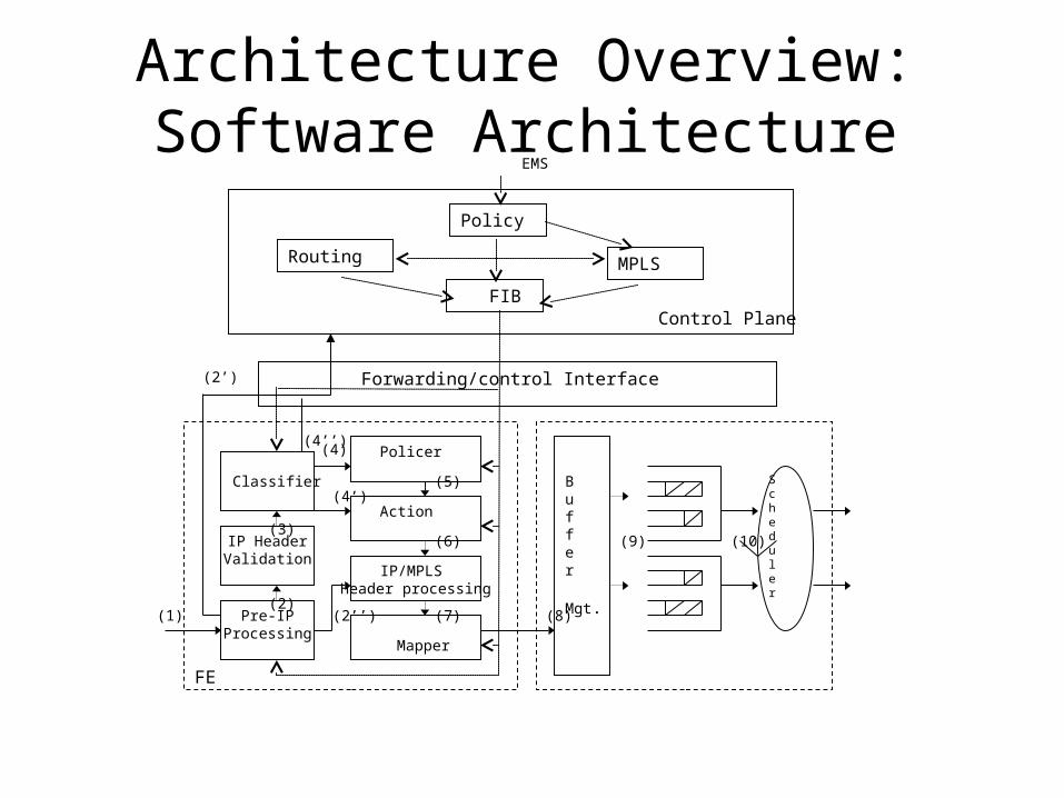
Data Path Processing• (1) The ingress Ethernet frame from an input port or frame from
switching fabric are validated and decapsulated. • (2’) For non-IP frames, such as PPP and IS-IS, Pre-IP Processing will result
in the frame PDU to be directly forwarded to the control card • (2”) For MPLS labeled packet which needs to be forwarded by label
swapping, the label swap table is looked up in the Pre-IP Processing module and the labeled packet is sent to the IP/MPLS header processing module for further processing
• (2) IP packet header information is validated• (3) In the Classifier, the Firewall/policy based classification and IP
forwarding table lookup are performed• (4) For DiffServ based filtering, classified packet flows are policed and
marked/remarked • (4’) For a non-DiffServ router or DiffServ router in the core, the policer
module may be bypassed, and the packet is acted upon based on the outcome of the Classifier.
Data Path Processing
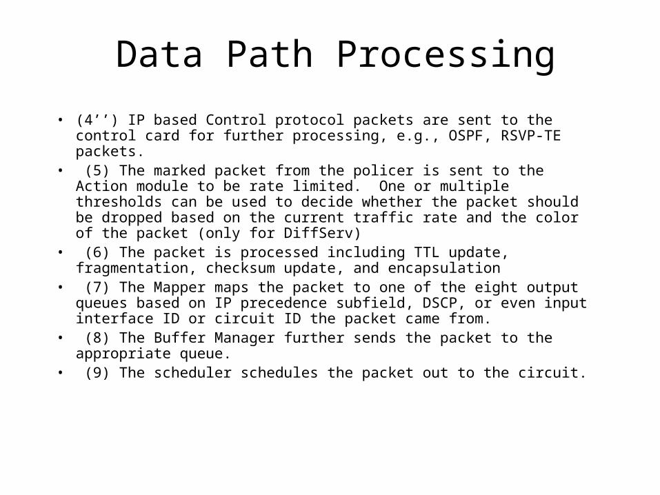
• (4’’) IP based Control protocol packets are sent to the control card for further processing, e.g., OSPF, RSVP-TE packets.
• (5) The marked packet from the policer is sent to the Action module to be rate limited. One or multiple thresholds can be used to decide whether the packet should be dropped based on the current traffic rate and the color of the packet (only for DiffServ)
• (6) The packet is processed including TTL update, fragmentation, checksum update, and encapsulation
• (7) The Mapper maps the packet to one of the eight output queues based on IP precedence subfield, DSCP, or even input interface ID or circuit ID the packet came from.
• (8) The Buffer Manager further sends the packet to the appropriate queue.
• (9) The scheduler schedules the packet out to the circuit.
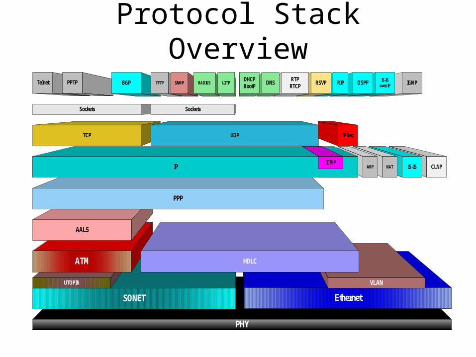
Protocol Stack Overview
CLNPIS-IS
PHY
SONET
UTOPIA
ATM
NAT
Ethernet
AAL5
PPP
ARPIPICMP
IP
IGMPIS-ISover IPOSPF
TCP UDP
Sockets
RIP
Sockets
RSVPTelnet PPTP BGP TFTPRTP
RTCPDNSSNMP RADIUS L2TP
DHCPBootP
IPSec
VLAN
HDLC
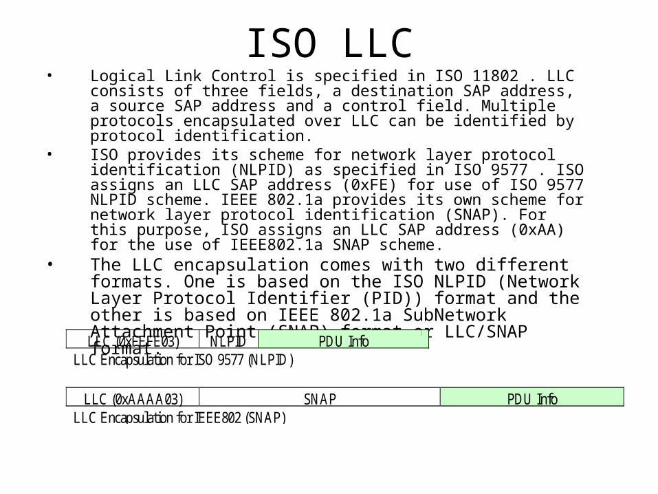
ISO LLC• Logical Link Control is specified in ISO 11802 . LLC consists of three
fields, a destination SAP address, a source SAP address and a control field. Multiple protocols encapsulated over LLC can be identified by protocol identification.
• ISO provides its scheme for network layer protocol identification (NLPID) as specified in ISO 9577 . ISO assigns an LLC SAP address (0xFE) for use of ISO 9577 NLPID scheme. IEEE 802.1a provides its own scheme for network layer protocol identification (SNAP). For this purpose, ISO assigns an LLC SAP address (0xAA) for the use of IEEE802.1a SNAP scheme.
• The LLC encapsulation comes with two different formats. One is based on the ISO NLPID (Network Layer Protocol Identifier (PID)) format and the other is based on IEEE 802.1a SubNetwork Attachment Point (SNAP) format or LLC/SNAP format.
LLC (0xFEFE03) NLPID PDU Info LLC Encapsulation for ISO 9577 (NLPID)
LLC (0xAAAA03) SNAP PDU Info LLC Encapsulation for IEEE802 (SNAP)
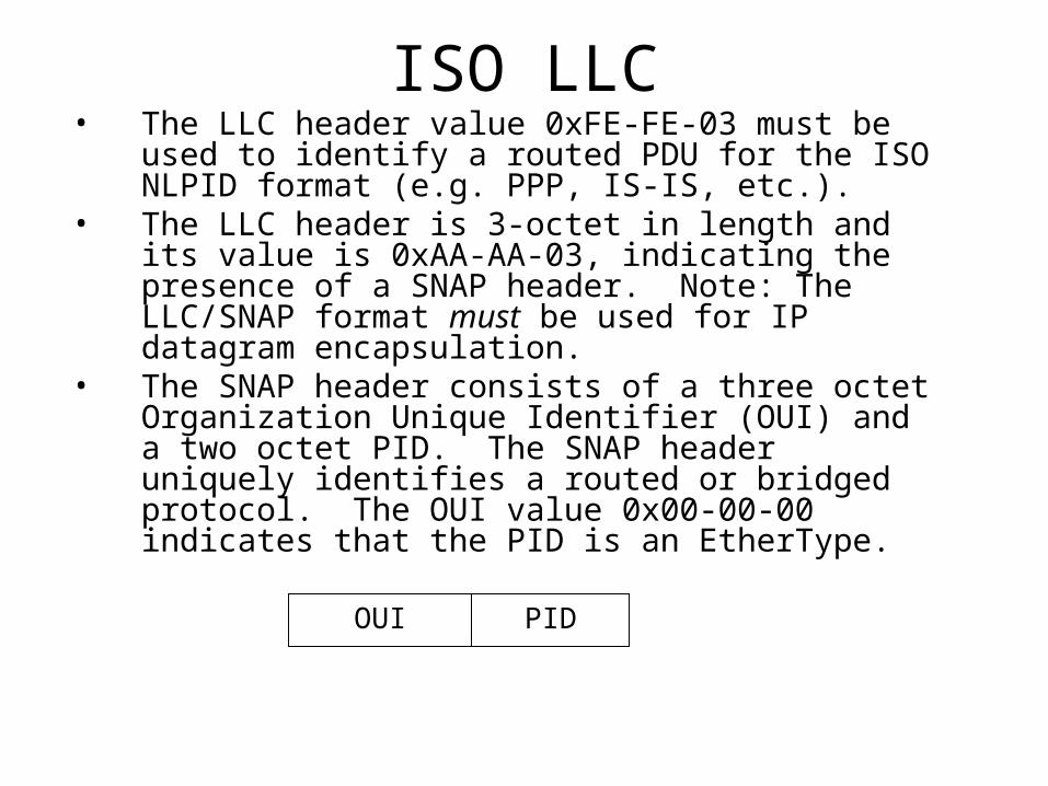
ISO LLC• The LLC header value 0xFE-FE-03 must be used to
identify a routed PDU for the ISO NLPID format (e.g. PPP, IS-IS, etc.).
• The LLC header is 3-octet in length and its value is 0xAA-AA-03, indicating the presence of a SNAP header. Note: The LLC/SNAP format must be used for IP datagram encapsulation.
• The SNAP header consists of a three octet Organization Unique Identifier (OUI) and a two octet PID. The SNAP header uniquely identifies a routed or bridged protocol. The OUI value 0x00-00-00 indicates that the PID is an EtherType.
PIDOUI
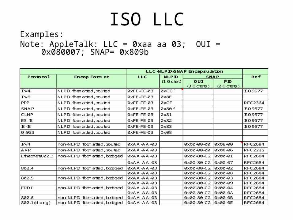
ISO LLCExamples:Note: AppleTalk: LLC = 0xaa aa 03; OUI = 0x080007; SNAP= 0x809b
OUI(3 Octets)
PID(2 Octets)
IPv4 NLPID formatted, routed 0xFE-FE-03 0xCC 1 ISO9577
IPv6 NLPID formatted, routed 0xFE-FE-03 0x8E
PPP NLPID formatted, routed 0xFE-FE-03 0xCF RFC2364
SNAP NLPID formatted, routed 0xFE-FE-03 0x80 2 ISO9577
CLNP NLPID formatted, routed 0xFE-FE-03 0x81 ISO9577
ES-IS NLPID formatted, routed 0xFE-FE-03 0x82 ISO9577
IS-IS NLPID formatted, routed 0xFE-FE-03 0x83 ISO9577
Q.933 NLPID formatted, routed 0xFE-FE-03 0x08
IPv4 non-NLPID formatted, routed 0xAA-AA-03 0x00-00-00 0x08-00 RFC2684
ARP non-NLPID formatted, routed 0xAA-AA-03 0x00-00-00 0x08-06 RFC2225
Ethernet/802.3 non-NLPID formatted, bridged 0xAA-AA-03 0x00-80-C2 0x00-01 RFC2684
0xAA-AA-03 0x00-80-C2 0x00-07 RFC2684
802.4 non-NLPID formatted, bridged 0xAA-AA-03 0x00-80-C2 0x00-02 RFC26840xAA-AA-03 0x00-80-C2 0x00-08 RFC2684
802.5 non-NLPID formatted, bridged 0xAA-AA-03 0x00-80-C2 0x00-03 RFC26840xAA-AA-03 0x00-80-C2 0x00-09 RFC2684
FDDI non-NLPID formatted, bridged 0xAA-AA-03 0x00-80-C2 0x00-04 RFC26840xAA-AA-03 0x00-80-C2 0x00-0A RFC2684
802.6 non-NLPID formatted, bridged 0xAA-AA-03 0x00-80-C2 0x00-0B RFC2684802.1(d or g) non-NLPID formatted, bridged 0xAA-AA-03 0x00-80-C2 0x00-0E RFC2684
Encap FormatProtocol Ref
LLC-NLPID/SNAP Encapsulation
SNAPLLC NLPID(1 Octet)
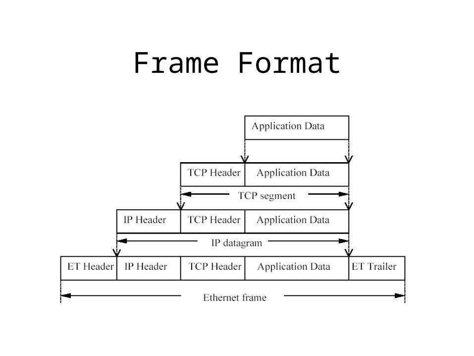
Frame Format

Ethernet Frame Format
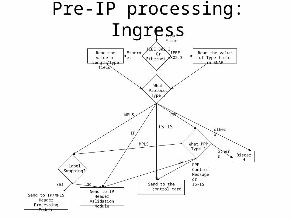
Pre-IP processing: Ingress
Read the value of Length/Type field
IP
Read the value of Type field in SNAP
IEEE 802.3Or
Ethernet ?
Ethernet IEEE 802.3
What Protocol Type ?
IS-IS
PPP
Discard
What PPP Type ?
IP
others
others
PPP Control MessageorIS-IS
Input Frame
Send to IP Header Validation Module
MPLS
Label Swapping?
NoYes
MPLS
Send to the control card
Send to IP/MPLS Header Processing
Module
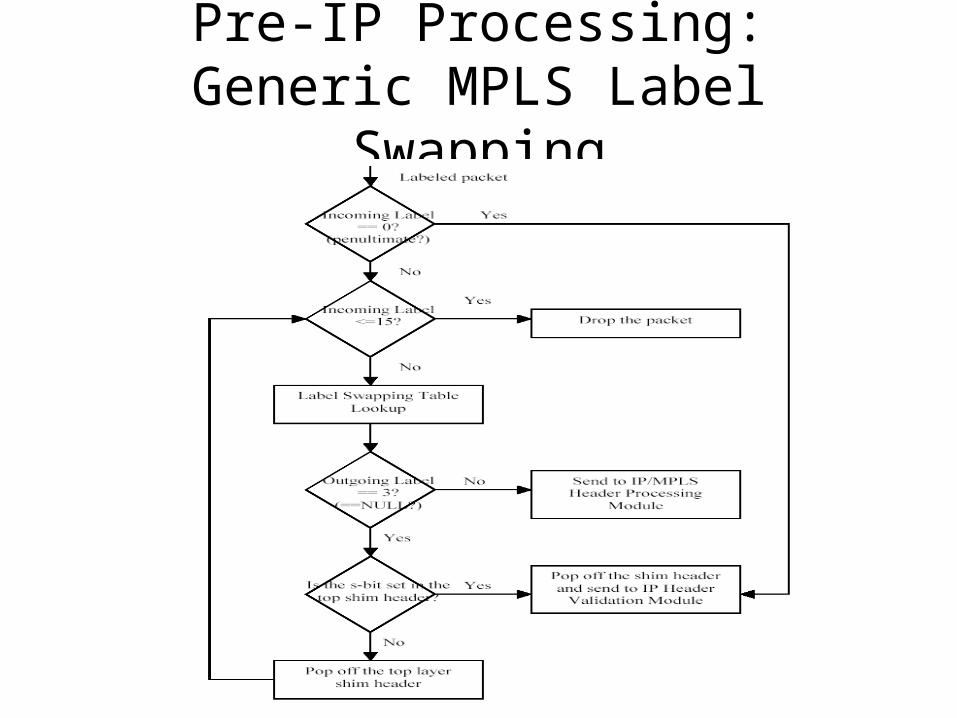
Pre-IP Processing: Generic MPLS Label Swapping
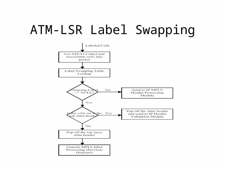
ATM-LSR Label Swapping
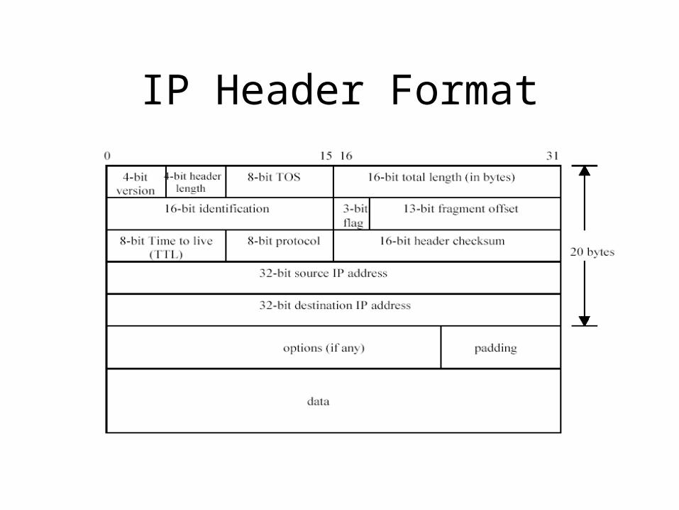
IP Header Format

TCP Header Format
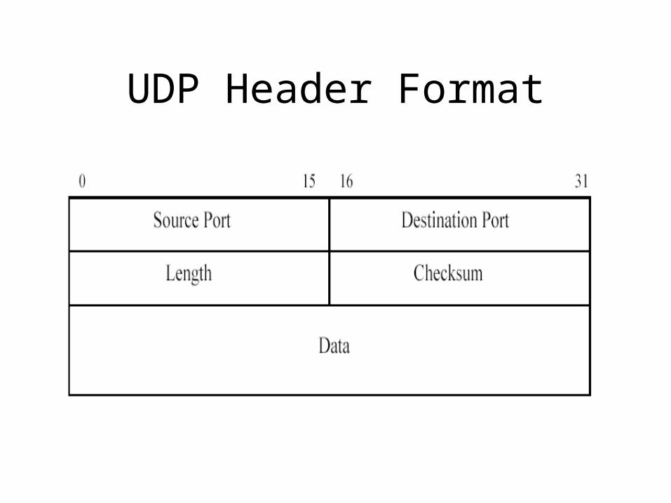
UDP Header Format

IP Header Validation

Search Key and Filter Rule
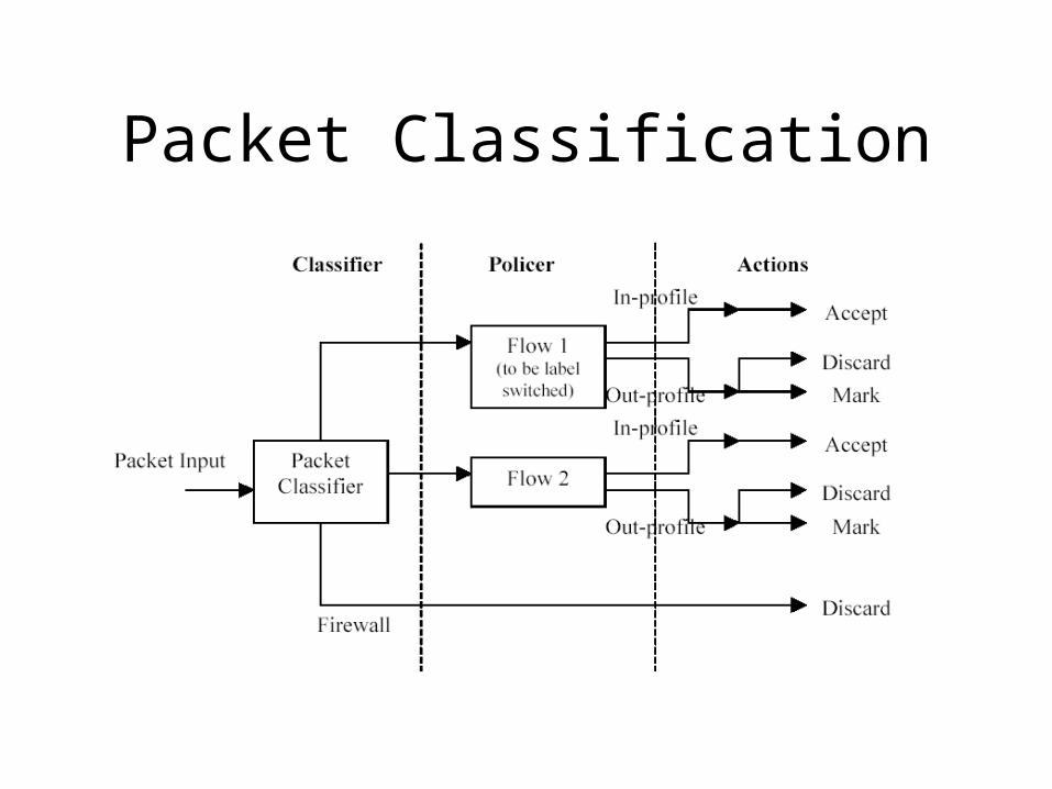
Packet Classification
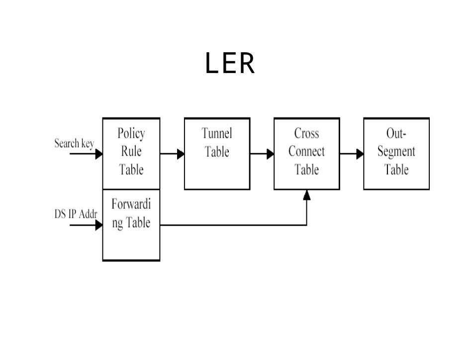
LER
Action Types
• Accept• Discard• Reject• Routing instance• Alert• Count• Log• DSCP set• Rate limit

IP/MPLS Header Processing: TTL Update
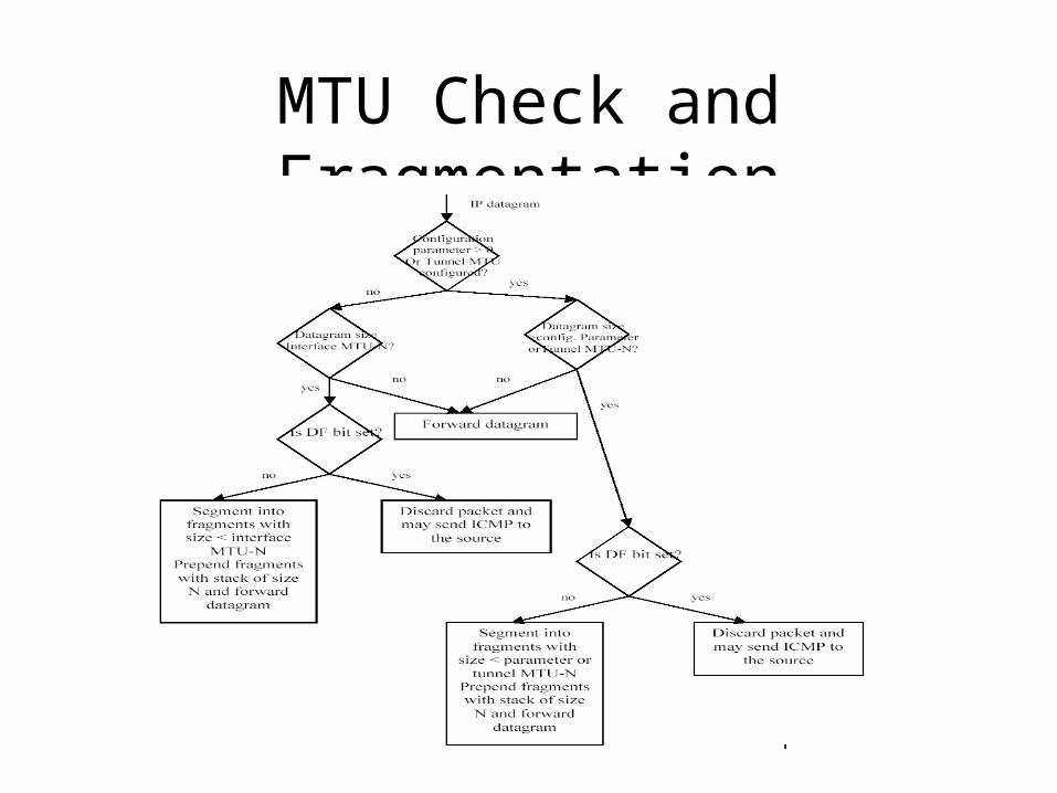
MTU Check and Fragmentation
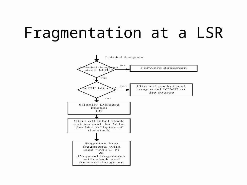
Fragmentation at a LSR
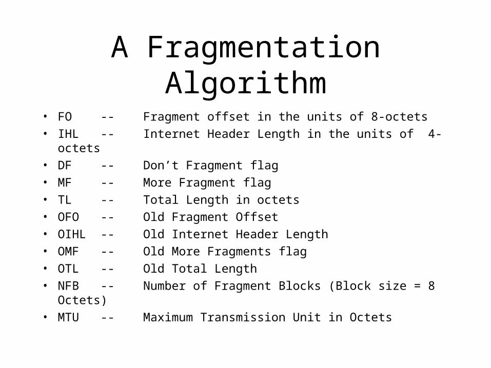
A Fragmentation Algorithm
• FO -- Fragment offset in the units of 8-octets
• IHL -- Internet Header Length in the units of 4-octets
• DF -- Don’t Fragment flag
• MF -- More Fragment flag
• TL -- Total Length in octets
• OFO -- Old Fragment Offset
• OIHL -- Old Internet Header Length
• OMF -- Old More Fragments flag
• OTL -- Old Total Length
• NFB -- Number of Fragment Blocks (Block size = 8 Octets)
• MTU -- Maximum Transmission Unit in Octets
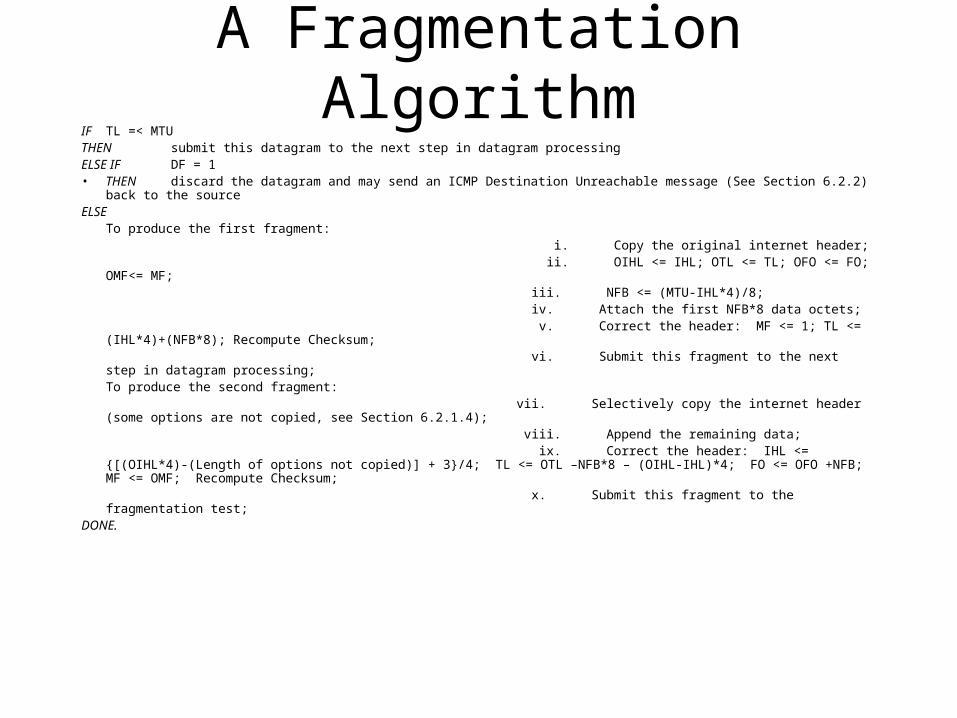
A Fragmentation AlgorithmIF TL =< MTU THEN submit this datagram to the next step in datagram processing ELSE IF DF = 1• THEN discard the datagram and may send an ICMP Destination Unreachable message (See Section 6.2.2) back to
the sourceELSE
To produce the first fragment: i. Copy the original internet header; ii. OIHL <= IHL; OTL <= TL; OFO <= FO; OMF<= MF; iii. NFB <= (MTU-IHL*4)/8; iv. Attach the first NFB*8 data octets; v. Correct the header: MF <= 1; TL <= (IHL*4)+(NFB*8); Recompute Checksum; vi. Submit this fragment to the next step in datagram processing; To produce the second fragment: vii. Selectively copy the internet header (some options are not copied, see Section
6.2.1.4); viii. Append the remaining data; ix. Correct the header: IHL <= {[(OIHL*4)-(Length of options not copied)] +
3}/4; TL <= OTL –NFB*8 – (OIHL-IHL)*4; FO <= OFO +NFB; MF <= OMF; Recompute Checksum; x. Submit this fragment to the fragmentation test; DONE.
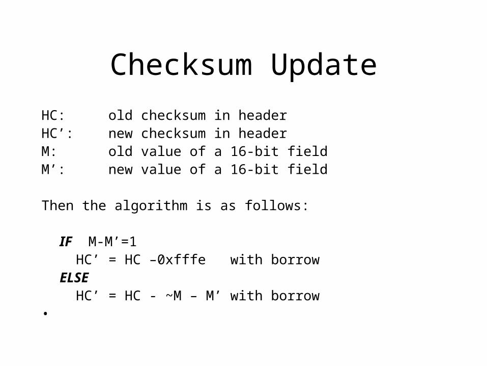
Checksum Update
HC: old checksum in headerHC’: new checksum in headerM: old value of a 16-bit fieldM’: new value of a 16-bit field Then the algorithm is as follows: IF M-M’=1 HC’ = HC –0xfffe with borrowELSE HC’ = HC - ~M – M’ with borrow
•

Fast or Slow Paths Forwarding
• Some gray areas:– ICMP– Options field – Packet fragmentation
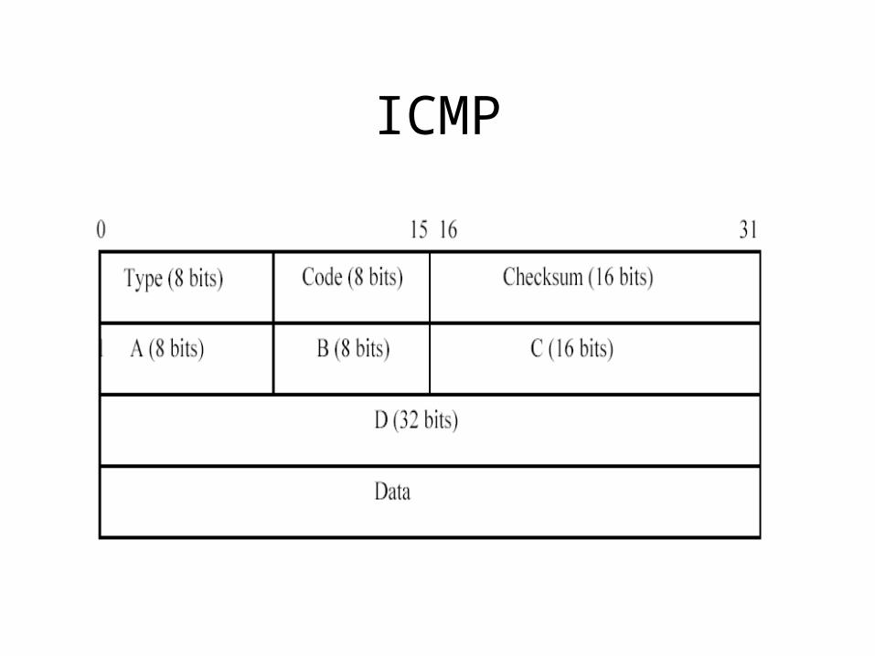
ICMP
ICMP
ICMP
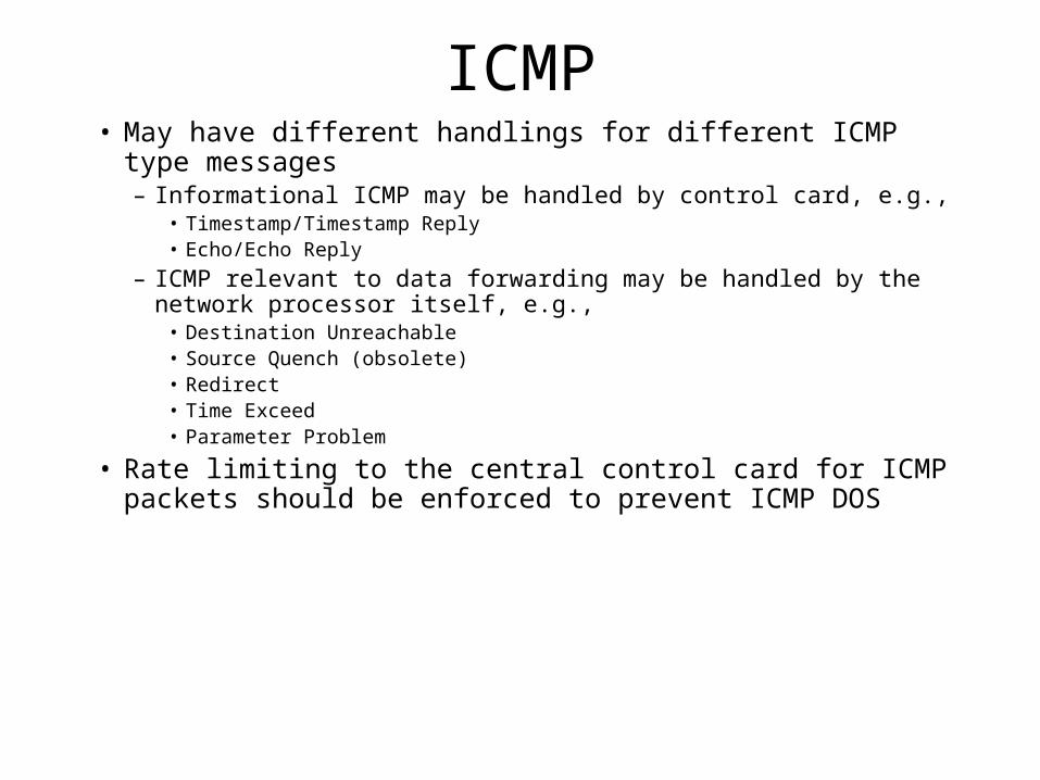
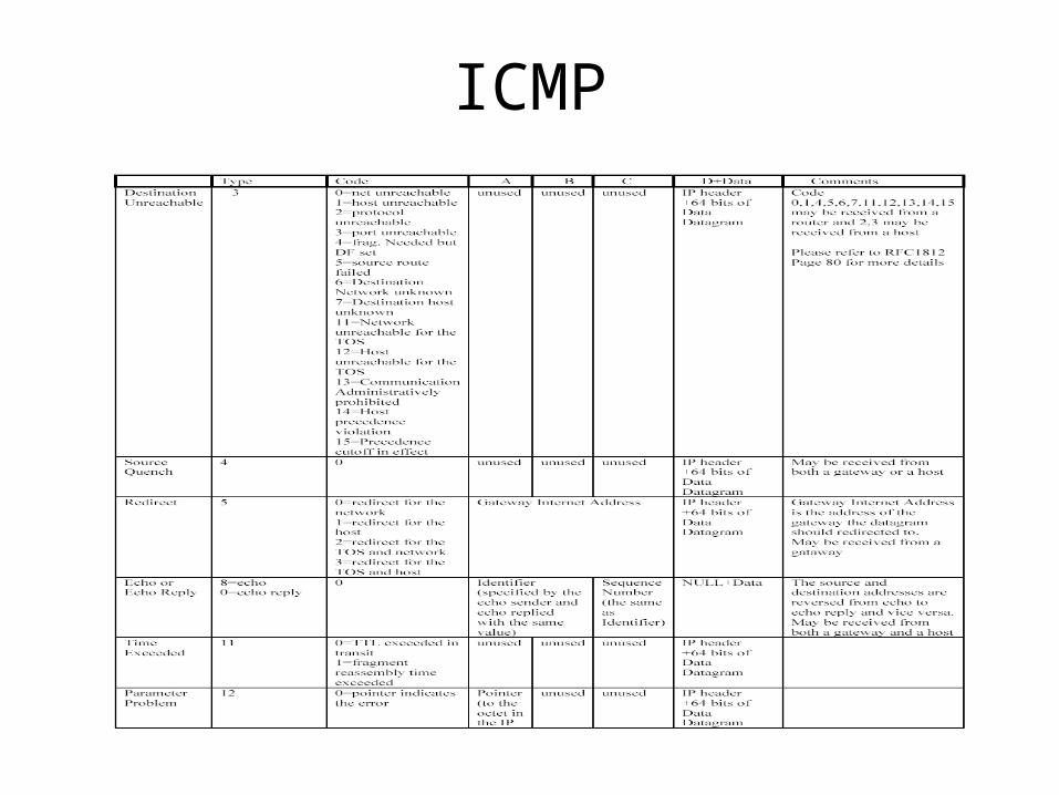
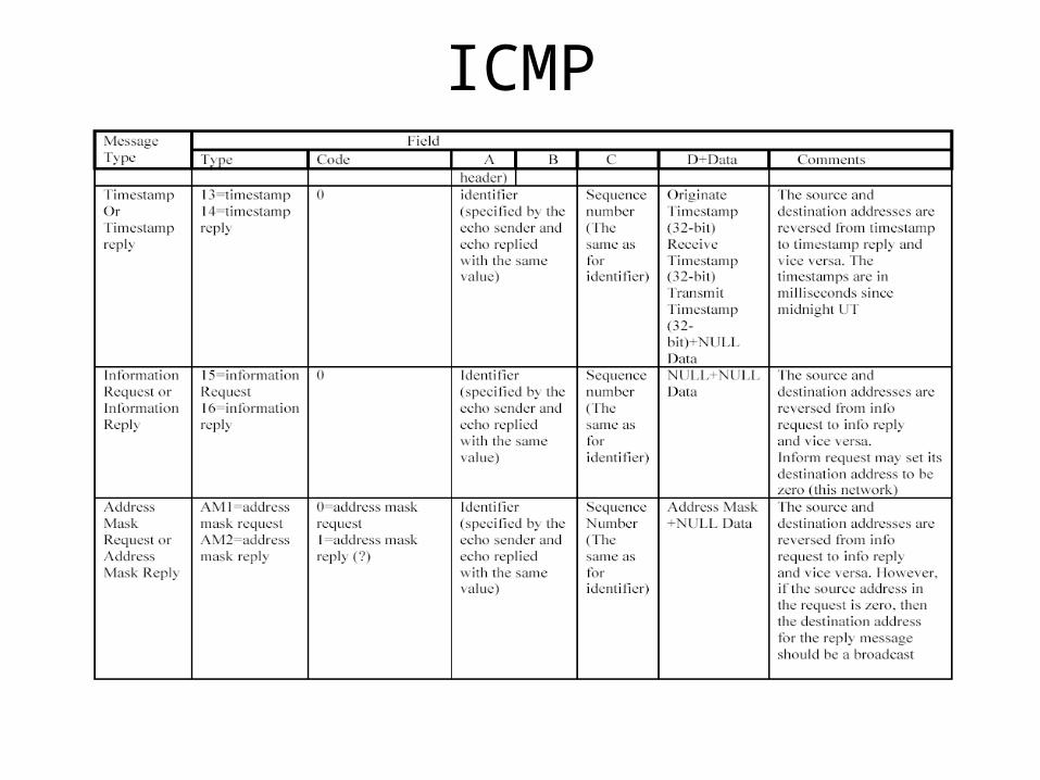
ICMP• May have different handlings for different ICMP type
messages– Informational ICMP may be handled by control card, e.g.,
• Timestamp/Timestamp Reply• Echo/Echo Reply
– ICMP relevant to data forwarding may be handled by the network processor itself, e.g.,
• Destination Unreachable • Source Quench (obsolete)• Redirect• Time Exceed• Parameter Problem
• Rate limiting to the central control card for ICMP packets should be enforced to prevent ICMP DOS
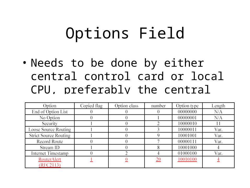
Options Field
• Needs to be done by either central control card or local CPU, preferably the central control card

Fragmentation• About 3% Internet traffic needs fragmentation• Slow path forwarding can be problematic
– An Example: for an OC-192 interface, the CPU has to handle 300Mbps traffic!

Fragmentation• Concept of Wire-speed forwardingAssumptions:
– A network processor working at 200 MHz clock rate or 5 ns– One instruction per clock cycle– There are 8 threads working in pipeline– Minimum frame size is 60 bytes– Line rate = 1 Gigabit per second
Per frame time = 60x8/1Gigabit = 480 nsInstruction budget = 480/5=96 instructions per packetLatency budget = 480x8 = 3840 ns Wire-speed: So long as the network processor is work conserving and the instruction
budget is not exceeded, wire-speed forwarding is maintained
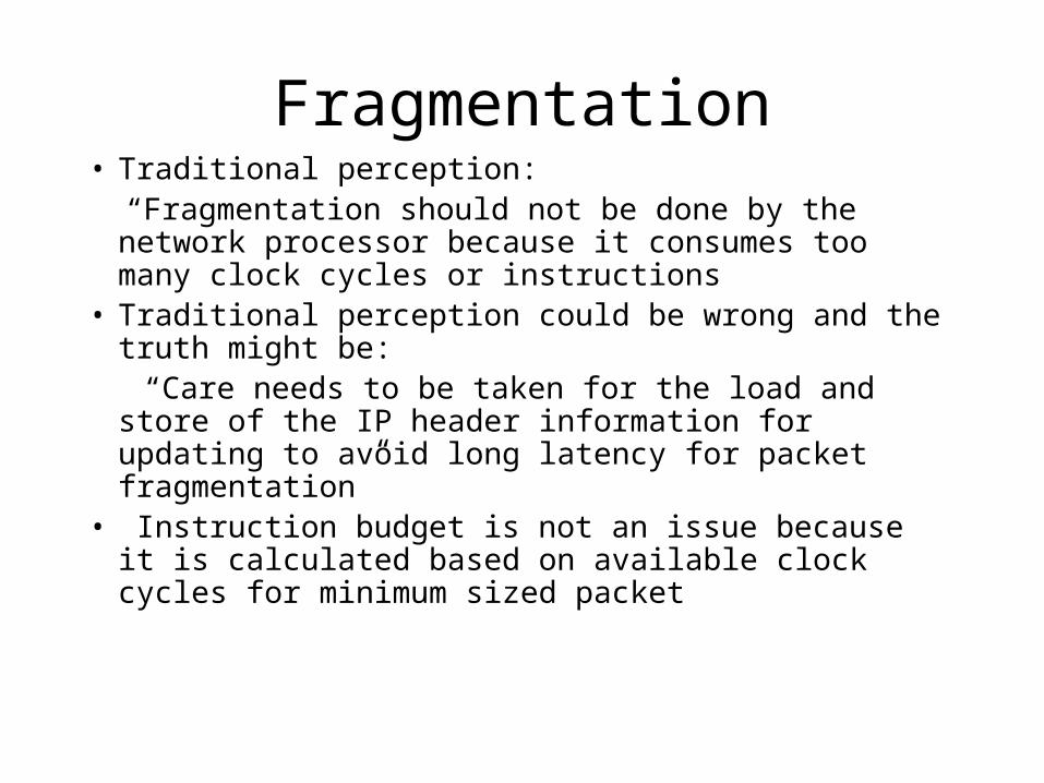
Fragmentation• Traditional perception: “Fragmentation should not be done by the network
processor because it consumes too many clock cycles or instructions
• Traditional perception could be wrong and the truth might be:
“Care needs to be taken for the load and store of the IP header information for updating to avoid long latency for packet fragmentation”
• Instruction budget is not an issue because it is calculated based on available clock cycles for minimum sized packet

Function Partitioning
• Why is it important?
• Distributed or Centralized?– Ideally local information should be handled by
local components, however, the need for information exchange between components sometimes call for centralized approach
– Components mainly involve control card/Central CPU, NICs, and local CPU,
Function Partitioning
• Examples:– Framing at ingress or egress NIC? – ARP and/or PPP running on local CPU or
central CPU? – Control plane functions running on local CPU
or central CPU?
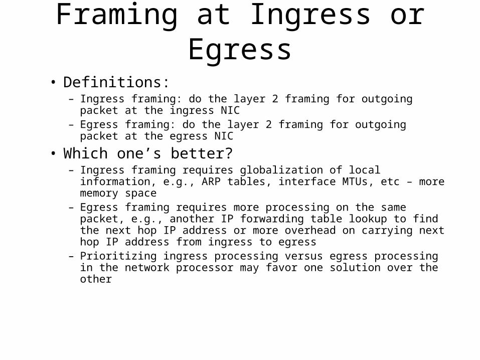
Framing at Ingress or Egress
• Definitions:– Ingress framing: do the layer 2 framing for outgoing packet at the
ingress NIC– Egress framing: do the layer 2 framing for outgoing packet at the
egress NIC
• Which one’s better?– Ingress framing requires globalization of local information, e.g., ARP
tables, interface MTUs, etc – more memory space– Egress framing requires more processing on the same packet, e.g.,
another IP forwarding table lookup to find the next hop IP address or more overhead on carrying next hop IP address from ingress to egress
– Prioritizing ingress processing versus egress processing in the network processor may favor one solution over the other

ARP Scope
• Within an IP subnet
• A physical interface may support multiple IP subnet
Router

ARP• Design choices:
– Distributed Solution• Run ARPs locally on the local CPUs in NICs
– Centralized Solution• Run ARPs on the central control processor
– Hybrid solution• Run ARPs locally but the ARP tables are centralized
• Impact of different design choices– Distributed solution is good when packet framing is done at the egress NICs– If packet framing is done at the ingress NICs, centralized solution may be
better– Hybrid solution can be a good choice when central control processor power
is constrained while packet framing needs to be done at the ingress NICs
PPP
Two main purposes for using PPP
• Broadband access, i.e., ADSL– Can be distributed or centralized depending on
how the subscriber management server is connected with the router
• Support for POS framing– Local to the POS interface, but centralized
control is OK
Card RedundancyBackground:• IP Internet was built with high resiliency in mind, i.e.,
recover from a link or node failure through:– rerouting without bounded delay, delay jitter, and loss guarantee– Packet recovery through transport layer retransmission
• When a node comes back, it takes the following steps for a routing domain to become stable:– Bring up the environment, i.e., RTOS– Activate the Processes for routing protocol stacks– Bring the IP interfaces up– Establish neighboring relationships through hello protocol
Card Redundancy
– Establish adjacency relationships– Bring the database in synch through topology information
flooding– Calculate the shortest path routes and create the FIB– Download the FIB into each NIC card to facilitate packet
classification and forwarding– Network wide stable state is reached after all the nodes in the
routing domain have done with the above steps
• In general, it takes 10s of seconds to 10s of minutes to reach a stable state, during that time period packets can be sent into a transient loop or black holed.
Card Redundancy
• To support mission critical and voice applications, resiliency alone is not sufficient
• High availability (e.g., 5 9s uptime) becomes an essential requirement for router design. Today’s ISPs cares more about the availability/reliability than price/performance
• A primary approach to achieve high availability is through card level redundancy
Card Redundancy
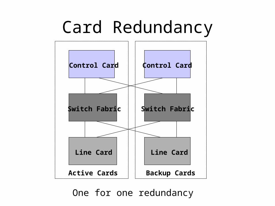
Control Card Control Card
Switch Fabric Switch Fabric
Line CardLine Card
Backup CardsActive Cards
One for one redundancy
Card Redundancy• Assume that most of the control plane functions are carried out
in the control card and the line cards make use of the FIB downloaded from the control card to perform data path functions
• The physical separation of the data path functions from the control path functions allows headless forwarding: during the switchover phase, line cards continue to forward packets based on the FIB info downloaded from the control card prior to switchover
• However, headless forwarding alone cannot achieve high availability, why?

Control Card Redundancy
• Control card switchover triggers: – Software upgrade– Hardware failure– Software failure
• Software failures can be further breakdown• Software bugs (e.g., memory leak, deadlock, etc.)• Reception of bad protocol info
• Software failures can also be classified into two failure types– Deterministic– Non-deterministic (e.g., due to race conditions)

Two Solutions
• Nonstop Routing – Hide the failure from all other nodes
• Nonstop Forwarding– Hide the failure from all other nodes except its
neighbors
Nonstop Routing
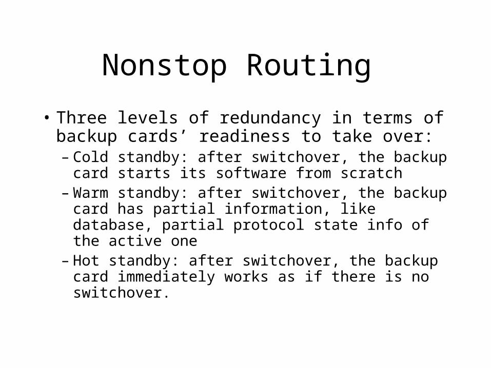
• Three levels of redundancy in terms of backup cards’ readiness to take over: – Cold standby: after switchover, the backup card
starts its software from scratch– Warm standby: after switchover, the backup
card has partial information, like database, partial protocol state info of the active one
– Hot standby: after switchover, the backup card immediately works as if there is no switchover.
Nonstop Routing
• Hot standby is relatively easy to implement for line cards and switch fabric
• It is very difficult to achieve hot standby for control cards
• Why?
Nonstop Routing
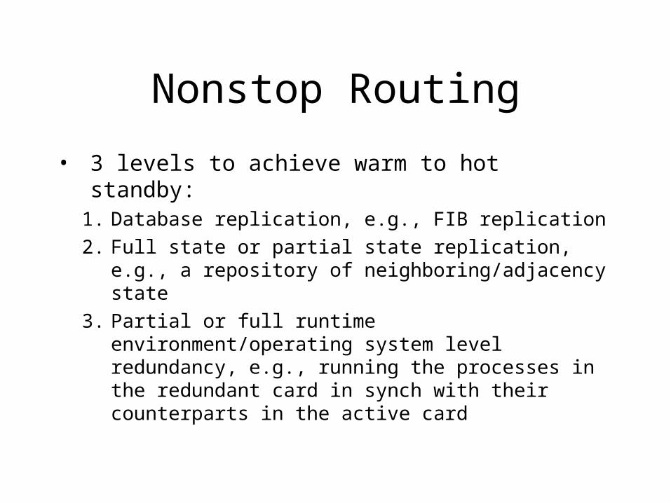
• 3 levels to achieve warm to hot standby: 1. Database replication, e.g., FIB replication
2. Full state or partial state replication, e.g., a repository of neighboring/adjacency state
3. Partial or full runtime environment/operating system level redundancy, e.g., running the processes in the redundant card in synch with their counterparts in the active card

Nonstop Routing
Level 1 redundancy: • the easiest to implement and is recommended to be
used by some routing software vendors, e.g., Ipinfusion and Data Connection Ltd
• Can deal with non-deterministic software failures • May recover from certain deterministic software
failures if the backup card runs a different version of the protocol software
• Has significant impact on network performance due to slow routing convergence
Nonstop Routing
Level 2 redundancy:
• Improves over level 1 by duplicating state information, in addition to database. It therefore improves routing convergence time
• FIB can still become stale due to system bring-up (or bootup) phase and state info retrieval phase
Nonstop Routing
Level 3 redundancy:
• Offers the highest level availability when software upgrade or hardware failure occurs
• Difficult to achieve since the backup card needs to run in lockstep with the primary card, or hot standby mode
• Cannot recover from software failures
Nonstop Routing
In practice:
• Combine three levels, example: – Full database replication– Partial state machine replication– Full TCP redundancy at operating system level
• Vendor solutions: – Alcatel, Avici, etc. (2002)
Nonstop Routing
A critical open issue:
• 60% of the failures due to software
• The existing solutions cannot deal with software failures well
• Any other solutions?
Nonstop Forwarding
An example: Hitless Restart• During switchover phase, tell all your
neighboring nodes to pretend nothing has gone wrong, and your neighbors, in turn, tell their neighbors that you are doing just fine
• Can this approach alone provides high availability, why or why not?
• A combined approach may be helpful