Embed Size (px)
Citation preview
MultiSync LCD2690WUXi2
MultiSync LCD2490WUXi2
User’s Manual
Index
Warning, Caution ........................................................................................................................ English-1
Declaration .................................................................................................................................. English-1
Canadian Department of Communications Compliance Statement ............................................ English-2
Declaration of Conformity ........................................................................................................... English-2
Contents ...................................................................................................................................... English-3
Quick Start .................................................................................................................................. English-4
Controls ....................................................................................................................................... English-8
Recommended use ..................................................................................................................... English-13
Specifications - LCD2690WUXi2 ................................................................................................ English-15
Specifications - LCD2490WUXi2 ................................................................................................ English-16
Features ...................................................................................................................................... English-17
Troubleshooting .......................................................................................................................... English-18
Advanced OSD ........................................................................................................................... English-19
Using the Auto Brightness function ............................................................................................. English-26
Using the PICTURE MODE function ........................................................................................... English-27
TCO’03 ........................................................................................................................................ English-28
Manufacturer’s Recycling and Energy Information ..................................................................... English-29

English-1
Eng
lishWARNING
CAUTIONCAUTION: TO REDUCE THE RISK OF ELECTRIC SHOCK, MAKE SURE POWER CORD IS UNPLUGGED FROM
WALL SOCKET. TO FULLY DISENGAGE THE POWER TO THE UNIT, PLEASE DISCONNECT THEPOWER CORD FROM THE AC OUTLET.DO NOT REMOVE COVER (OR BACK). NO USERSERVICEABLE PARTS INSIDE. REFER SERVICING TO QUALIFIED SERVICE PERSONNEL.
This symbol warns user that uninsulated voltage within the unit may have sufficient magnitude to causeelectric shock. Therefore, it is dangerous to make any kind of contact with any part inside this unit.
This symbol alerts the user that important literature concerning the operation and maintenance of this unithas been included. Therefore, it should be read carefully in order to avoid any problems.
TO PREVENT FIRE OR SHOCK HAZARDS, DO NOT EXPOSE THIS UNIT TO RAIN OR MOISTURE. ALSO, DO NOTUSE THIS UNIT'S POLARIZED PLUG WITH AN EXTENSION CORD RECEPTACLE OR OTHER OUTLETS UNLESSTHE PRONGS CAN BE FULLY INSERTED.
REFRAIN FROM OPENING THE CABINET AS THERE ARE HIGH VOLTAGE COMPONENTS INSIDE. REFERSERVICING TO QUALIFIED SERVICE PERSONNEL.
Declaration
Declaration of the Manufacturer
We hereby certify that the color monitor MultiSyncLCD2690WUXi2 (L266RZ) and MultiSyncLCD2490WUXi2 (L246T0) are in compliance with:
Council Directive 2006/95/EC:– EN 60950-1
Council Directive 2004/108/EC:– EN 55022– EN 61000-3-2– EN 61000-3-3– EN 55024
and marked with
NEC Display Solutions, Ltd.4-13-23, Shibaura,
Minato-KuTokyo 108-0023, Japan
Windows is a registered trademark of Microsoft Corporation. NEC is a registered trademark of NEC Corporation.ENERGY STAR is a U.S. registered trademark.ErgoDesign is a registered trademark of NEC Display Solutions, Ltd. in Austria, Benelux, Denmark, France, Germany, Italy, Norway, Spain,Sweden, U.K.All other brands and product names are trademarks or registered trademarks of their respective owners.As an ENERGY STAR® Partner, NEC Display Solutions of America, Inc. has determined that this product meets the ENERGY STAR guidelines forenergy efficiency. The ENERGY STAR emblem does not represent EPA endorsement of any product or service.Adobe® is a registered trademark or trademark of Adobe Systems Incorporated in the U.S. and/or other countries.
CAUTION: Please use the power cord provided with this display in accordance with the table below. If a power cord is notsupplied with this equipment, please contact your supplier. For all other cases, please use a power cord that matches theAC voltage of the power outlet and has been approved by and complies with the safety standard of your particular country.
Plug Type North AmericaEuropean
ContinentalU.K. Chinese Japanese
Plug Shape
Country
Voltage
U.S.A./Canada U.K. China JapanEU (except U.K.)
120* 230 220 100230
*When operating the MultiSync LCD2690WUXi2 or MultiSync LCD2490WUXi2 monitor with its AC 125-240V power supply,use a power supply cord that matches the power supply voltage of the AC power outlet being used.
NOTE: This product can only be serviced in the country where it was purchased.
English-2
Canadian Department of Communications ComplianceStatementDOC: This Class B digital apparatus meets all requirements of the Canadian Interference-Causing Equipment Regulations.
C-UL: Bears the C-UL Mark and is in compliance with Canadian Safety Regulations according to CAN/CSA C22.2 No. 60950-1.
FCC Information1. Use the attached specified cables with the MultiSync LCD2690WUXi2 or MultiSync LCD2490WUXi2 color monitor so
as not to interfere with radio and television reception.
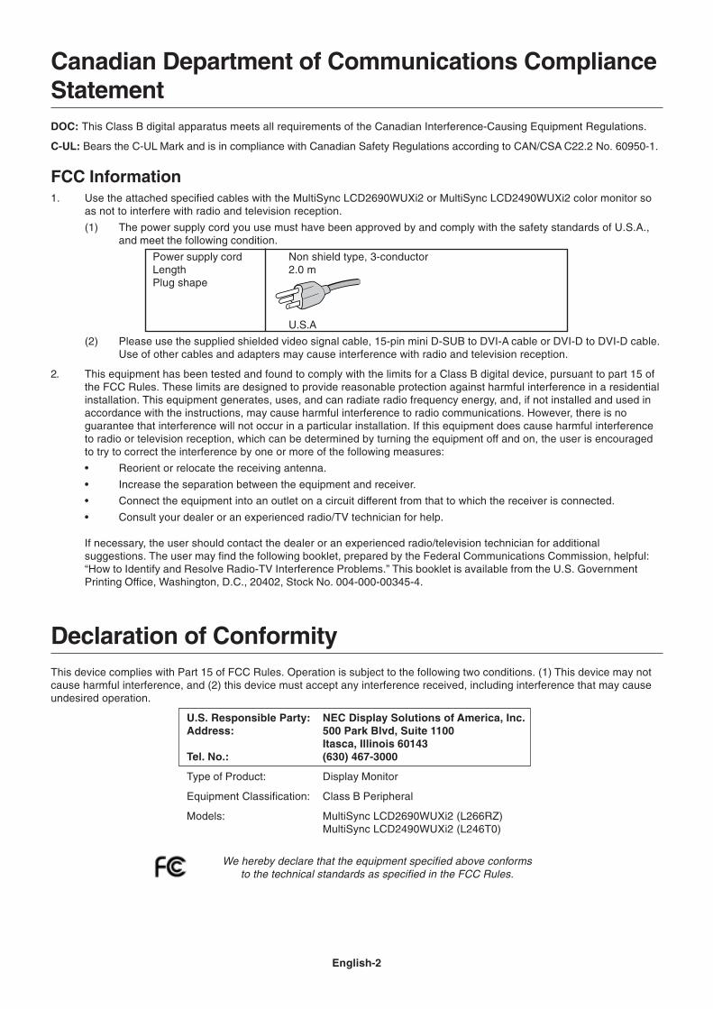
(1) The power supply cord you use must have been approved by and comply with the safety standards of U.S.A.,and meet the following condition.
Power supply cord Non shield type, 3-conductorLength 2.0 mPlug shape
U.S.A
(2) Please use the supplied shielded video signal cable, 15-pin mini D-SUB to DVI-A cable or DVI-D to DVI-D cable.Use of other cables and adapters may cause interference with radio and television reception.
2. This equipment has been tested and found to comply with the limits for a Class B digital device, pursuant to part 15 ofthe FCC Rules. These limits are designed to provide reasonable protection against harmful interference in a residentialinstallation. This equipment generates, uses, and can radiate radio frequency energy, and, if not installed and used inaccordance with the instructions, may cause harmful interference to radio communications. However, there is noguarantee that interference will not occur in a particular installation. If this equipment does cause harmful interferenceto radio or television reception, which can be determined by turning the equipment off and on, the user is encouragedto try to correct the interference by one or more of the following measures:
• Reorient or relocate the receiving antenna.
• Increase the separation between the equipment and receiver.
• Connect the equipment into an outlet on a circuit different from that to which the receiver is connected.
• Consult your dealer or an experienced radio/TV technician for help.
If necessary, the user should contact the dealer or an experienced radio/television technician for additionalsuggestions. The user may find the following booklet, prepared by the Federal Communications Commission, helpful:“How to Identify and Resolve Radio-TV Interference Problems.” This booklet is available from the U.S. GovernmentPrinting Office, Washington, D.C., 20402, Stock No. 004-000-00345-4.
Declaration of ConformityThis device complies with Part 15 of FCC Rules. Operation is subject to the following two conditions. (1) This device may notcause harmful interference, and (2) this device must accept any interference received, including interference that may causeundesired operation.
U.S. Responsible Party: NEC Display Solutions of America, Inc.Address: 500 Park Blvd, Suite 1100
Itasca, Illinois 60143Tel. No.: (630) 467-3000
Type of Product: Display Monitor
Equipment Classification: Class B Peripheral
Models: MultiSync LCD2690WUXi2 (L266RZ)MultiSync LCD2490WUXi2 (L246T0)
We hereby declare that the equipment specified above conformsto the technical standards as specified in the FCC Rules.

English-3
Eng
lishContents
Your new NEC monitor box* should contain the following:
• MultiSync LCD2690WUXi2 or MultiSync LCD2490WUXi2 monitor with tilt/swivel/pivot/height adjust stand
• Power Cord
• Video Signal Cable (15-pin mini D-SUB male to DVI-A)
• Video Signal Cable (DVI-D to DVI-D cable)
• Video Signal Cable (Mini D-SUB 15 pin to Mini D-SUB 15 pin) (For U.S. and China)
• User’s Manual
• CD-ROM
• Cable Cover
• Screw (x 4) (to mount the monitor to a flexible arm (page 7))
User’s Manual DVI-D to DVI-D cable Cable Cover
CD-ROM
15-pin mini D-SUB male to DVI-A
Screws
* Remember to save your original box and packing material to transport or ship the monitor.
NOTE: This monitor can be equipped with optionalloudspeakers: “MultiSync Sound bar”.Please ask your dealer or check our websitehttp://www.necdsiplaysolution.com
Power Cord(Type of power cord included will
depend on the where the LCDmonitor is to be shipped)
User’s Manual
Mini D-SUB 15 pin toMini D-SUB 15 pin
(For U.S. and China)
English-4
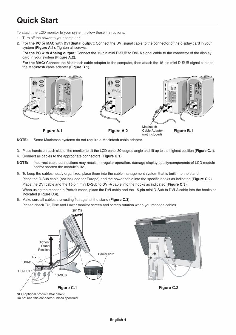
Figure C.1 Figure C.2
HighestStand
Position
Quick StartTo attach the LCD monitor to your system, follow these instructions:
1. Turn off the power to your computer.
2. For the PC or MAC with DVI digital output: Connect the DVI signal cable to the connector of the display card in yoursystem (Figure A.1). Tighten all screws.
For the PC with Analog output: Connect the 15-pin mini D-SUB to DVI-A signal cable to the connector of the displaycard in your system (Figure A.2).
For the MAC: Connect the Macintosh cable adapter to the computer, then attach the 15-pin mini D-SUB signal cable tothe Macintosh cable adapter (Figure B.1).
NOTE: Some Macintosh systems do not require a Macintosh cable adapter.
3. Place hands on each side of the monitor to tilt the LCD panel 30-degree angle and lift up to the highest position (Figure C.1).
4. Connect all cables to the appropriate connectors (Figure C.1).
NOTE: Incorrect cable connections may result in irregular operation, damage display quality/components of LCD moduleand/or shorten the module’s life.
5. To keep the cables neatly organized, place them into the cable management system that is built into the stand.
Place the D-Sub cable (not included for Europe) and the power cable into the specific hooks as indicated (Figure C.2).
Place the DVI cable and the 15-pin mini D-Sub to DVI-A cable into the hooks as indicated (Figure C.3).
When using the monitor in Portrait mode, place the DVI cable and the 15-pin mini D-Sub to DVI-A cable into the hooks asindicated (Figure C.4).
6. Make sure all cables are resting flat against the stand (Figure C.3).
Please check Tilt, Rise and Lower monitor screen and screen rotation when you manage cables.
Figure A.1 Figure B.1MacintoshCable Adapter(not included)
Figure A.2
Power cord
30˚ Tilt
DC-OUT
DVI-D
DVI-I
D-SUB
NEC optional product attachment.Do not use this connector unless specified.
English-5
Eng
lish
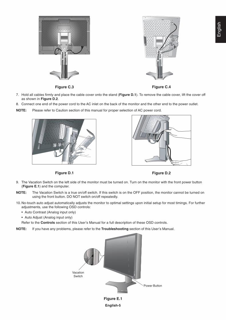
Figure E.1
VacationSwitch
Power Button
Figure C.3
Figure D.1 Figure D.2
Figure C.4
7. Hold all cables firmly and place the cable cover onto the stand (Figure D.1). To remove the cable cover, lift the cover offas shown in Figure D.2.
8. Connect one end of the power cord to the AC inlet on the back of the monitor and the other end to the power outlet.
NOTE: Please refer to Caution section of this manual for proper selection of AC power cord.
9. The Vacation Switch on the left side of the monitor must be turned on. Turn on the monitor with the front power button(Figure E.1) and the computer.
NOTE: The Vacation Switch is a true on/off switch. If this switch is on the OFF position, the monitor cannot be turned onusing the front button. DO NOT switch on/off repeatedly.
10. No-touch auto adjust automatically adjusts the monitor to optimal settings upon initial setup for most timings. For furtheradjustments, use the following OSD controls:
• Auto Contrast (Analog input only)
• Auto Adjust (Analog input only)
Refer to the Controls section of this User’s Manual for a full description of these OSD controls.
NOTE: If you have any problems, please refer to the Troubleshooting section of this User’s Manual.
English-6
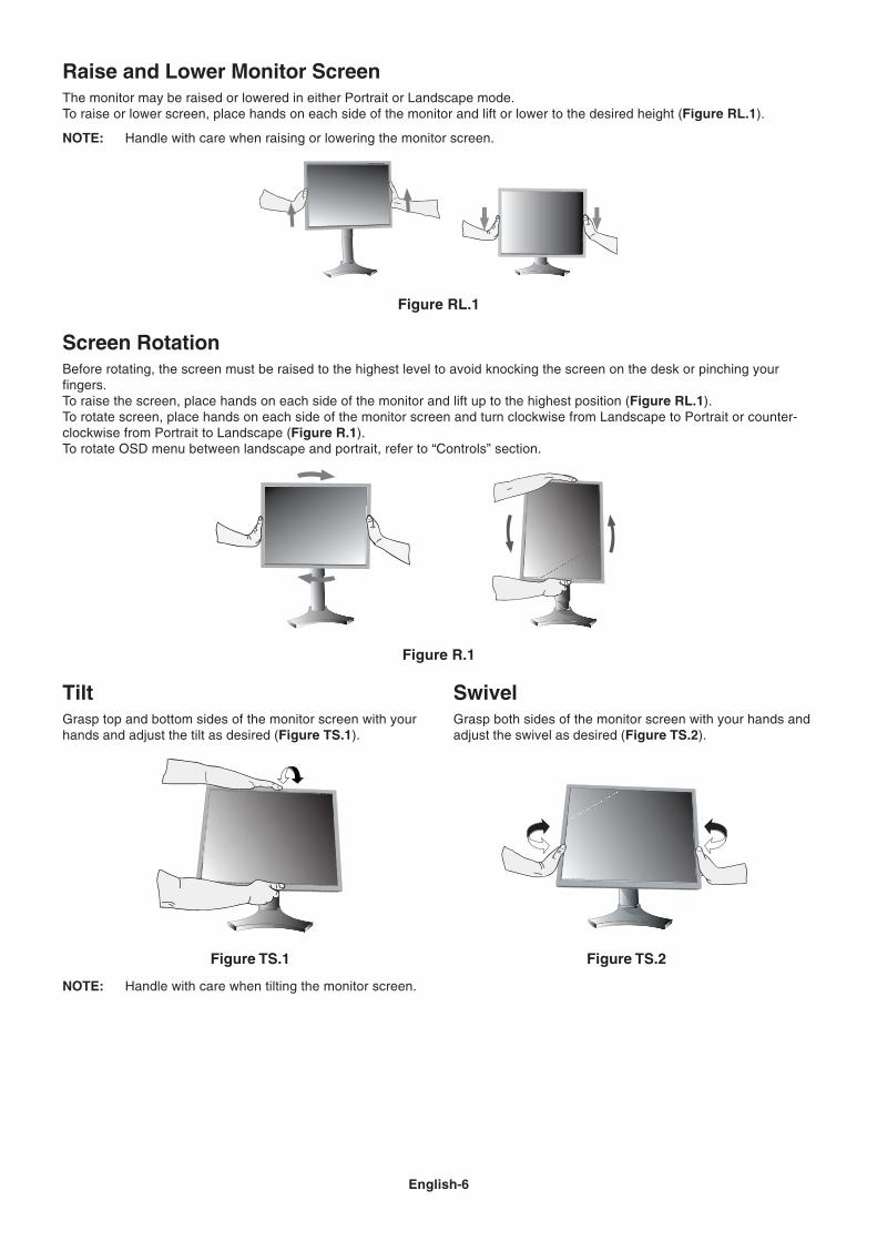
TiltGrasp top and bottom sides of the monitor screen with yourhands and adjust the tilt as desired (Figure TS.1).
Figure TS.1
SwivelGrasp both sides of the monitor screen with your hands andadjust the swivel as desired (Figure TS.2).
NOTE: Handle with care when tilting the monitor screen.
Figure TS.2
Screen RotationBefore rotating, the screen must be raised to the highest level to avoid knocking the screen on the desk or pinching yourfingers.To raise the screen, place hands on each side of the monitor and lift up to the highest position (Figure RL.1).To rotate screen, place hands on each side of the monitor screen and turn clockwise from Landscape to Portrait or counter-clockwise from Portrait to Landscape (Figure R.1).To rotate OSD menu between landscape and portrait, refer to “Controls” section.
Figure R.1
Figure RL.1
Raise and Lower Monitor ScreenThe monitor may be raised or lowered in either Portrait or Landscape mode.To raise or lower screen, place hands on each side of the monitor and lift or lower to the desired height (Figure RL.1).
NOTE: Handle with care when raising or lowering the monitor screen.
English-7
Eng
lish
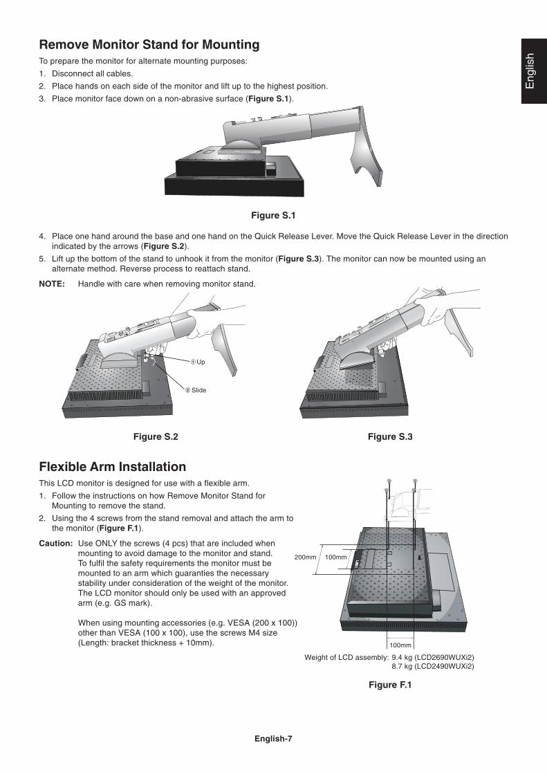
Figure S.1
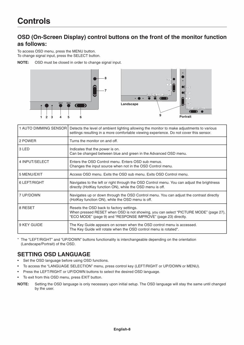
4. Place one hand around the base and one hand on the Quick Release Lever. Move the Quick Release Lever in the directionindicated by the arrows (Figure S.2).
5. Lift up the bottom of the stand to unhook it from the monitor (Figure S.3). The monitor can now be mounted using analternate method. Reverse process to reattach stand.
NOTE: Handle with care when removing monitor stand.
Figure S.2
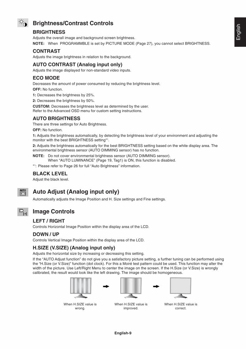
Flexible Arm InstallationThis LCD monitor is designed for use with a flexible arm.
1. Follow the instructions on how Remove Monitor Stand forMounting to remove the stand.
2. Using the 4 screws from the stand removal and attach the arm tothe monitor (Figure F.1).
Caution: Use ONLY the screws (4 pcs) that are included whenmounting to avoid damage to the monitor and stand.To fulfil the safety requirements the monitor must bemounted to an arm which guaranties the necessarystability under consideration of the weight of the monitor.The LCD monitor should only be used with an approvedarm (e.g. GS mark).
When using mounting accessories (e.g. VESA (200 x 100))other than VESA (100 x 100), use the screws M4 size(Length: bracket thickness + 10mm).
Figure S.3
Remove Monitor Stand for MountingTo prepare the monitor for alternate mounting purposes:
1. Disconnect all cables.
2. Place hands on each side of the monitor and lift up to the highest position.
3. Place monitor face down on a non-abrasive surface (Figure S.1).
100mm
100mm
Figure F.1
Up
Slide
200mm
Weight of LCD assembly: 9.4 kg (LCD2690WUXi2)8.7 kg (LCD2490WUXi2)
English-8
Controls
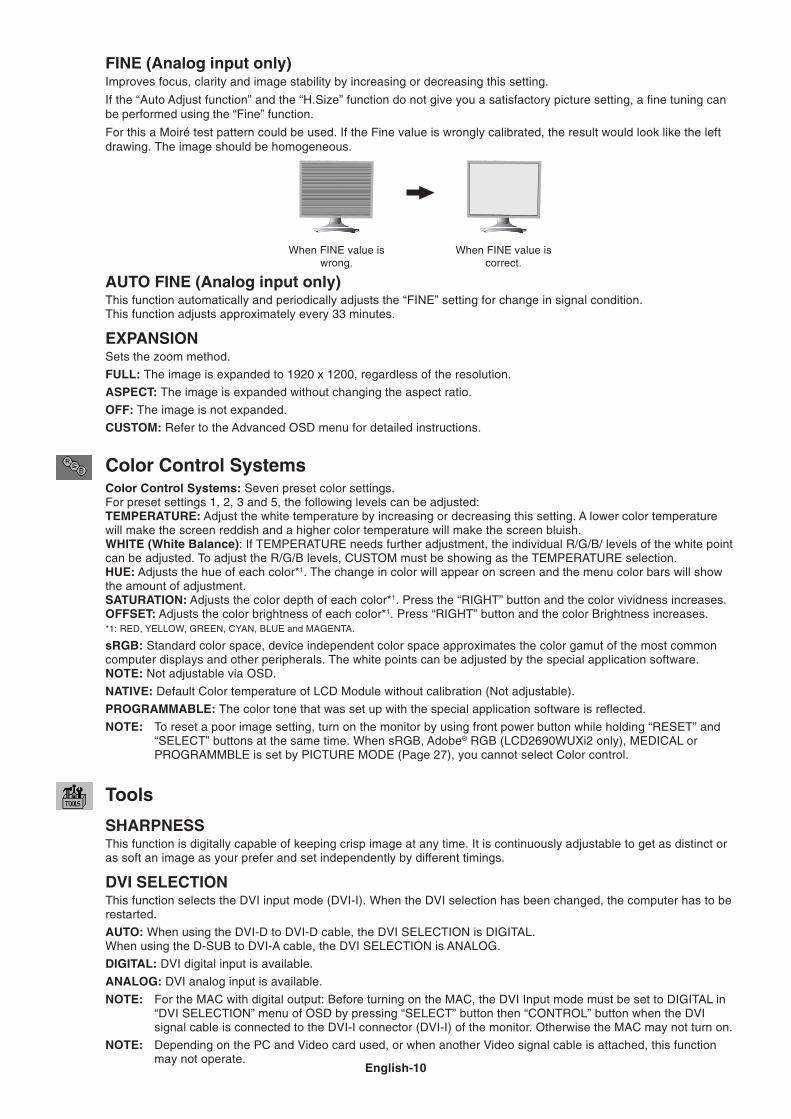
OSD (On-Screen Display) control buttons on the front of the monitor functionas follows:To access OSD menu, press the MENU button.To change signal input, press the SELECT button.
NOTE: OSD must be closed in order to change signal input.
* The “LEFT/RIGHT” and “UP/DOWN” buttons functionality is interchangeable depending on the orientation(Landscape/Portrait) of the OSD.
SETTING OSD LANGUAGE• Set the OSD language before using OSD functions.
• To access the “LANGUAGE SELECTION” menu, press control key (LEFT/RIGHT or UP/DOWN or MENU).
• Press the LEFT/RIGHT or UP/DOWN buttons to select the desired OSD language.
• To exit from this OSD menu, press EXIT button.
NOTE: Setting the OSD language is only necessary upon initial setup. The OSD language will stay the same until changedby the user.
Detects the level of ambient lighting allowing the monitor to make adjustments to varioussettings resulting in a more comfortable viewing experience. Do not cover this sensor.
Turns the monitor on and off.
Indicates that the power is on.Can be changed between blue and green in the Advanced OSD menu.
Enters the OSD Control menu. Enters OSD sub menus.Changes the input source when not in the OSD Control menu.
Access OSD menu. Exits the OSD sub menu. Exits OSD Control menu.
Navigates to the left or right through the OSD Control menu. You can adjust the brightnessdirectly (HotKey function ON), while the OSD menu is off.
Navigates up or down through the OSD Control menu. You can adjust the contrast directly(HotKey function ON), while the OSD menu is off.
Resets the OSD back to factory settings.When pressed RESET when OSD is not showing, you can select “PICTURE MODE” (page 27),“ECO MODE” (page 9) and “RESPONSE IMPROVE” (page 23) directly.
The Key Guide appears on screen when the OSD control menu is accessed.The Key Guide will rotate when the OSD control menu is rotated*.
1 AUTO DIMMING SENSOR
2 POWER
3 LED
4 INPUT/SELECT
5 MENU/EXIT
6 LEFT/RIGHT
7 UP/DOWN
8 RESET
9 KEY GUIDE
1 2 3 4 5 6
7
8
9
Landscape
Portrait
English-9
Eng
lishBrightness/Contrast Controls
BRIGHTNESSAdjusts the overall image and background screen brightness.
NOTE: When PROGRAMMBLE is set by PICTURE MODE (Page 27), you cannot select BRIGHTNESS.
CONTRASTAdjusts the image brightness in relation to the background.
AUTO CONTRAST (Analog input only)Adjusts the image displayed for non-standard video inputs.
ECO MODEDecreases the amount of power consumed by reducing the brightness level.
OFF: No function.
1: Decreases the brightness by 25%.
2: Decreases the brightness by 50%.
CUSTOM: Decreases the brightness level as determined by the user.Refer to the Advanced OSD menu for custom setting instructions.
AUTO BRIGHTNESSThere are three settings for Auto Brightness.
OFF: No function.
1: Adjusts the brightness automatically, by detecting the brightness level of your environment and adjusting themonitor with the best BRIGHTNESS setting*1.
2: Adjusts the brightness automatically for the best BRIGHTNESS setting based on the white display area. Theenvironmental brightness sensor (AUTO DIMMING sensor) has no function.
NOTE: Do not cover environmental brightness sensor (AUTO DIMMING sensor).When “AUTO LUMINANCE” (Page 19, Tag1) is ON, this function is disabled.
*1: Please refer to Page 26 for full “Auto Brightness” information.
BLACK LEVELAdjust the black level.
Auto Adjust (Analog input only)Automatically adjusts the Image Position and H. Size settings and Fine settings.
Image Controls
LEFT / RIGHTControls Horizontal Image Position within the display area of the LCD.
DOWN / UPControls Vertical Image Position within the display area of the LCD.
H.SIZE (V.SIZE) (Analog input only)Adjusts the horizontal size by increasing or decreasing this setting.
If the “AUTO Adjust function” do not give you a satisfactory picture setting, a further tuning can be performed usingthe “H.Size (or V.Size)” function (dot clock). For this a Moiré test pattern could be used. This function may alter thewidth of the picture. Use Left/Right Menu to center the image on the screen. If the H.Size (or V.Size) is wronglycalibrated, the result would look like the left drawing. The image should be homogeneous.
When H.SIZE value iswrong.
When H.SIZE value isimproved.
When H.SIZE value iscorrect.
English-10
FINE (Analog input only)Improves focus, clarity and image stability by increasing or decreasing this setting.
If the “Auto Adjust function” and the “H.Size” function do not give you a satisfactory picture setting, a fine tuning canbe performed using the “Fine” function.
For this a Moiré test pattern could be used. If the Fine value is wrongly calibrated, the result would look like the leftdrawing. The image should be homogeneous.
When FINE value iswrong.
When FINE value iscorrect.
AUTO FINE (Analog input only)This function automatically and periodically adjusts the “FINE” setting for change in signal condition.This function adjusts approximately every 33 minutes.
EXPANSIONSets the zoom method.
FULL: The image is expanded to 1920 x 1200, regardless of the resolution.
ASPECT: The image is expanded without changing the aspect ratio.
OFF: The image is not expanded.
CUSTOM: Refer to the Advanced OSD menu for detailed instructions.
Color Control SystemsColor Control Systems: Seven preset color settings.For preset settings 1, 2, 3 and 5, the following levels can be adjusted:TEMPERATURE: Adjust the white temperature by increasing or decreasing this setting. A lower color temperaturewill make the screen reddish and a higher color temperature will make the screen bluish.WHITE (White Balance): If TEMPERATURE needs further adjustment, the individual R/G/B/ levels of the white pointcan be adjusted. To adjust the R/G/B levels, CUSTOM must be showing as the TEMPERATURE selection.HUE: Adjusts the hue of each color*1. The change in color will appear on screen and the menu color bars will showthe amount of adjustment.SATURATION: Adjusts the color depth of each color*1. Press the “RIGHT” button and the color vividness increases.OFFSET: Adjusts the color brightness of each color*1. Press “RIGHT” button and the color Brightness increases.*1: RED, YELLOW, GREEN, CYAN, BLUE and MAGENTA.
sRGB: Standard color space, device independent color space approximates the color gamut of the most commoncomputer displays and other peripherals. The white points can be adjusted by the special application software.NOTE: Not adjustable via OSD.
NATIVE: Default Color temperature of LCD Module without calibration (Not adjustable).
PROGRAMMABLE: The color tone that was set up with the special application software is reflected.
NOTE: To reset a poor image setting, turn on the monitor by using front power button while holding “RESET” and“SELECT” buttons at the same time. When sRGB, Adobe® RGB (LCD2690WUXi2 only), MEDICAL orPROGRAMMBLE is set by PICTURE MODE (Page 27), you cannot select Color control.
Tools
SHARPNESSThis function is digitally capable of keeping crisp image at any time. It is continuously adjustable to get as distinct oras soft an image as your prefer and set independently by different timings.
DVI SELECTIONThis function selects the DVI input mode (DVI-I). When the DVI selection has been changed, the computer has to berestarted.
AUTO: When using the DVI-D to DVI-D cable, the DVI SELECTION is DIGITAL.When using the D-SUB to DVI-A cable, the DVI SELECTION is ANALOG.
DIGITAL: DVI digital input is available.
ANALOG: DVI analog input is available.
NOTE: For the MAC with digital output: Before turning on the MAC, the DVI Input mode must be set to DIGITAL in“DVI SELECTION” menu of OSD by pressing “SELECT” button then “CONTROL” button when the DVIsignal cable is connected to the DVI-I connector (DVI-I) of the monitor. Otherwise the MAC may not turn on.
NOTE: Depending on the PC and Video card used, or when another Video signal cable is attached, this functionmay not operate.
English-11
Eng
lish
EDID EXTENSION (Digital Input Only)Selects the type of input to be used with EDID EXTENSION.
NORMAL: When a PC or other computer equipment is connected, select “NORMAL”.
ENHANCED: When a DVD player or other type of high definition device is connected, select “ENHANCED”.
NOTE: Interlaced signals (480i, 576i, 1080i) are not supported. If you have any problems, please refer to theTroubleshooting section of this User’s Manual.When EDID EXTENSION has been changed, the connected equipment has to be restarted.
VIDEO DETECTSelects the method of video detection when more than one video input is connected.
FIRST: When current video input signal is not present, then the monitor searches for a video signal from the othervideo input port. If the video signal is present in the other port, then the monitor switches the video source input portto the new found video source automatically. The monitor will not look for other video signals while the current videosource is present.
LAST: When the monitor is displaying a signal from the current source and a new secondary source is supplied tothe monitor, then the monitor will automatically switch to the new video source. When current video input signal is notpresent, then the monitor searches for a video signal from the other video input port. If the video signal is present inthe other port, then the monitor switches the video source input port to the new found video source automatically.
NONE: The Monitor will not search the other video input port unless the monitor is turned on.
OFF TIMERMonitor will automatically power-down when the end user has selected a pre-determined amount of time.Before powering off, a message will appear on the screen asking the user if they want to delay the turn off timeby 60 minutes. Press any OSD button to delay the turn off time.
OFF MODEThe Intelligent Power Manager allows the monitor to enter into a power saving mode after a period of inactivity.
The OFF MODE has three settings.
OFF: Monitor does not go into power save mode when the input signal is lost.
STANDARD: Monitor enters power save mode automatically when the input signal is lost.
OPTION: Monitor enters power save mode automatically when the amount of surrounding light goes below the levelthat is determined by the user. The level can be adjusted in Tag 7 of the Advanced OSD menu.
When in power save mode, the LED on the front of the monitor blinks amber. While in power save mode, push any ofthe front buttons, except for POWER and SELECT to return to normal.
When the amount of surrounding light returns to normal levels, the monitor will automatically return to normal mode.
UNIFORMITYThis function electronically compensates for the slight variations in the white uniformity level, as well as fordeviations in color that may occur throughout the display area of the screen. These variations are characteristic ofLCD panel technology. This function improves the color and evens out the luminance uniformity of the display.
NOTE: Using the UNIFORMITY feature reduces the overall peak luminance of the display. If greater luminance isdesired over the uniform performance of the display, then UNIFORMITY should be turned off.
MENU Tools
LANGUAGEOSD control menus are available in eight languages.
OSD LEFT/RIGHTYou can choose where you would like the OSD control image to appear on your screen. Selecting OSD Locationallows you to manually adjust the position of the OSD control menu left or right.
OSD DOWN/UPYou can choose where you would like the OSD control image to appear on your screen. Selecting OSD Locationallows you to manually adjust the position of the OSD control menu Up or Down.
OSD TURN OFFThe OSD control menu will stay on as long as it is use. You can select how long the monitor waits after the last touchof a button to shut off the OSD control menu. The preset choices are 10-120 seconds by 5-second increments.
English-12
OSD LOCK OUTThis control completely locks out access to all OSD control functions. When attempting to activate OSD controlswhile in the Lock Out mode, a screen will appear indicating the OSD controls are locked out.
There are four types of OSD LOCK OUT:
OSD LOCK OUT with BRIGHTNESS and CONTRAST control: To activate the OSD Lock Out function, pressSELECT, then “UP” button and hold down simultaneously. To deactivate the OSD Lock Out, press SELECT, then“UP” button and hold down simultaneously while in the OSD menu. BRIGHTNESS and CONTRAST can be adjustedwhile in this lock out mode.
OSD LOCK OUT with no control: To activate the OSD Lock Out function, press SELECT, then “Right” button andhold down simultaneously. To deactivate the OSD Lock Out, press SELECT, then “Right” button and hold downsimultaneously while in the OSD menu. No controls can be adjusted while in the lock out mode.
OSD LOCK OUT with BRIGHTNESS (only) control: To activate the OSD Lock Out function, press SELECT, then“Down” and “Left” buttons and hold down simultaneously. To deactivate the OSD Lock Out, press SELECT, then“Down” and “Left” buttons and hold down simultaneously while in the OSD menu. BRIGHTNESS can be adjustedwhile in this lock out mode.
CUSTOM: Refer to the Advanced OSD Menu.
OSD TRANSPARENCYAdjusts the transparency of the OSD Menu.
OSD COLOR“Tag window frame color”, “Item select color” and “Adjust window frame color” can be changed to Red, Green, Blue,or Gray.
RESOLUTION NOTIFIERThis optimal resolution is 1920 x 1200. If ON is selected, a message will appear on the screen after 30 seconds,notifying you that the resolution is not at 1920 x 1200.
HOT KEYYou can adjust the BRIGHTNESS and CONTRAST directly. When this function is set to ON, you can adjust thebrightness with “Left” or “Right” and the contrast with “Down” or “Up” buttons, while the OSD menu is off. Thestandard OSD can be accessed with the EXIT button.
FACTORY PRESETSelecting Factory Preset allows you to reset all OSD control settings (BRIGHTNESS, CONTRAST, ECOMODE,AUTO BRIGHTNESS, BLACK LEVEL, IMAGE CONTROL, COLOR CONTROL SYSTEM, SHARPNESS, OFF TIMER,OFF MODE, OSD LEFT/RIGHT, OSD UP/DOWN, OSD TURN OFF, OSD TRANSPARENCY) back to the factorysettings. Individual settings can be reset by highlighting the control to be reset and pressing the RESET button.
InformationProvides information about the current resolution display and technical data including the preset timing being usedand the horizontal and vertical frequencies. Indicates the model and serial numbers of your monitor.
OSD WarningOSD Warning menus disappear with EXIT button.
NO SIGNAL: This function gives a warning when there is no Horizontal or Vertical Sync. After power isturned on or when there is a change of input signal, the No Signal window will appear.
RESOLUTION NOTIFIER: This function warms if resolution other than the optimized resolution is used.After power is turned on or when there is a change of input signal or the video signal doesn’t have properresolution, the Resolution Notifier window will open. This function can be disabled in the MENU Tools.
OUT OF RANGE: This function gives a recommendation of the optimized resolution and refresh rate. Afterthe power is turned on or there is a change of input signal or if the video signal doesn’t have proper timing,the Out Of Range menu will appear.
PORTRAIT WARNING: When the monitor is used in the portrait position, the brightness value will bereduced to 250 cd/m2. If the Portrait Warning is ON, a message warning of the change in brightness willappear on the screen for 10 seconds.
LUMINANCE WARNING: When the backlight cannot display the desired luminance, a message willappear on the display. To avoid this, reduce the BRIGHTNESS level or set the AUTO LUMINANCEfunction to OFF (page 19, TAG1).
NOTE: It is possible to change the DVI SELECTION, to change the OFF MODE or to change the EDIDEXTENSION settings while the “NO SIGNAL” or “OUT OF RANGE” messages are displayed.
If you need detailed information about the controls, please use the ADVANCED OSD menu.
English-13
Eng
lishRecommended use
Safety Precautions and Maintenance
FOR OPTIMUM PERFORMANCE, PLEASE NOTETHE FOLLOWING WHEN SETTING UP AND
USING THE LCD COLOR MONITOR:
• DO NOT OPEN THE MONITOR. There are no user serviceable parts inside and opening or removing covers mayexpose you to dangerous shock hazards or other risks. Refer all servicing to qualified service personnel.
• Do not spill any liquids into the cabinet or use your monitor near water.
• Do not insert objects of any kind into the cabinet slots, as they may touch dangerous voltage points, which can be harmfulor fatal or may cause electric shock, fire or equipment failure.
• Do not place any heavy objects on the power cord. Damage to the cord may cause shock or fire.
• Do not place this product on a sloping or unstable cart, stand or table, as the monitor may fall, causing serious damage tothe monitor.
• The power supply cord you use must have been approved by and comply with the safety standards of your country.(Type H05VV-F 3G 1mm2 should be used in Europe).
• In UK, use a BS-approved power cord with molded plug having a black (5A) fuse installed for use with this monitor.
• Do not place any objects onto the monitor and do not use the monitor outdoors.
• The lamps in this product contain mercury. Please dispose according to state, local or federal law.• Do not bend power cord.
• Do not use monitor in high temperatured, humid, dusty, or oily areas.
• Do not cover vent on monitor.
• Vibration can damage the backlight. Do not install where the monitor will be exposed to continual vibration.
• If monitor or glass is broken, do not come in contact with the liquid crystal and handle with care.
Immediately turn off the power, unplug your monitor from the wall outlet and move to a safe location then refer servicing toqualified service personnel under the following conditions. If the monitor is used in this condition, the monitor may causefall, fire and electric shock:
• If the monitor stand has been cracked or peeled.
• If the monitor has been wobbled.
• If the monitor has an unusual odor.
• When the power supply cord or plug is damaged.
• If liquid has been spilled, or objects have fallen into the monitor.
• If the monitor has been exposed to rain or water.
• If the monitor has been dropped or the cabinet damaged.
• If the monitor does not operate normally by following operating instructions.
• Allow adequate ventilation around the monitor so that heat can properly dissipate. Do not block ventilatedopenings or place the monitor near a radiator or other heat sources. Do not put anything on top ofmonitor.
• The power cable connector is the primary means of detaching the system from the power supply. Themonitor should be installed close to a power outlet which is easily accessible.
• Handle with care when transporting. Save packaging for transporting.
• Do not touch LCD panel surface while transporting, mounting and setting. Applying pressure on the LCDpanel can cause serious damage.
Image Persistence: Image persistence is when a residual or “ghost” image of a previous image remains visible on the screen.Unlike CRT monitors, LCD monitors’ image persistence is not permanent, but constant images being displayed for a longperiod of time should be avoided.
To alleviate image persistence, turn off the monitor for as long as the previous image was displayed. For example, if animage was on the monitor for one hour and a residual image remains, the monitor should be turned off for one hour toerase the image.
NOTE: As with all personal display devices, NEC DISPLAY SOLUTIONS recommends using a moving screen saver atregular intervals whenever the screen is idle or turning off the monitor when not in use.
CAUTION
English-14
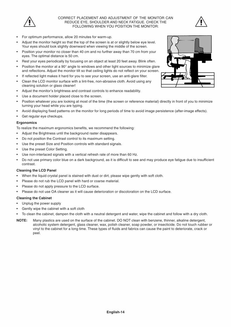
CORRECT PLACEMENT AND ADJUSTMENT OF THE MONITOR CANREDUCE EYE, SHOULDER AND NECK FATIGUE. CHECK THE
FOLLOWING WHEN YOU POSITION THE MONITOR:
• For optimum performance, allow 20 minutes for warm-up.
• Adjust the monitor height so that the top of the screen is at or slightly below eye level.Your eyes should look slightly downward when viewing the middle of the screen.
• Position your monitor no closer than 40 cm and no further away than 70 cm from youreyes. The optimal distance is 50 cm.
• Rest your eyes periodically by focusing on an object at least 20 feet away. Blink often.
• Position the monitor at a 90° angle to windows and other light sources to minimize glareand reflections. Adjust the monitor tilt so that ceiling lights do not reflect on your screen.
• If reflected light makes it hard for you to see your screen, use an anti-glare filter.
• Clean the LCD monitor surface with a lint-free, non-abrasive cloth. Avoid using anycleaning solution or glass cleaner!
• Adjust the monitor’s brightness and contrast controls to enhance readability.
• Use a document holder placed close to the screen.
• Position whatever you are looking at most of the time (the screen or reference material) directly in front of you to minimizeturning your head while you are typing.
• Avoid displaying fixed patterns on the monitor for long periods of time to avoid image persistence (after-image effects).
• Get regular eye checkups.
Ergonomics
To realize the maximum ergonomics benefits, we recommend the following:
• Adjust the Brightness until the background raster disappears.
• Do not position the Contrast control to its maximum setting.
• Use the preset Size and Position controls with standard signals.
• Use the preset Color Setting.
• Use non-interlaced signals with a vertical refresh rate of more than 60 Hz.
• Do not use primary color blue on a dark background, as it is difficult to see and may produce eye fatigue due to insufficientcontrast.
Cleaning the LCD Panel
• When the liquid crystal panel is stained with dust or dirt, please wipe gently with soft cloth.
• Please do not rub the LCD panel with hard or coarse material.
• Please do not apply pressure to the LCD surface.
• Please do not use OA cleaner as it will cause deterioration or discoloration on the LCD surface.
Cleaning the Cabinet
• Unplug the power supply
• Gently wipe the cabinet with a soft cloth
• To clean the cabinet, dampen the cloth with a neutral detergent and water, wipe the cabinet and follow with a dry cloth.
NOTE: Many plastics are used on the surface of the cabinet. DO NOT clean with benzene, thinner, alkaline detergent,alcoholic system detergent, glass cleaner, wax, polish cleaner, soap powder, or insecticide. Do not touch rubber orvinyl to the cabinet for a long time. These types of fluids and fabrics can cause the paint to deteriorate, crack orpeel.
English-15
Eng
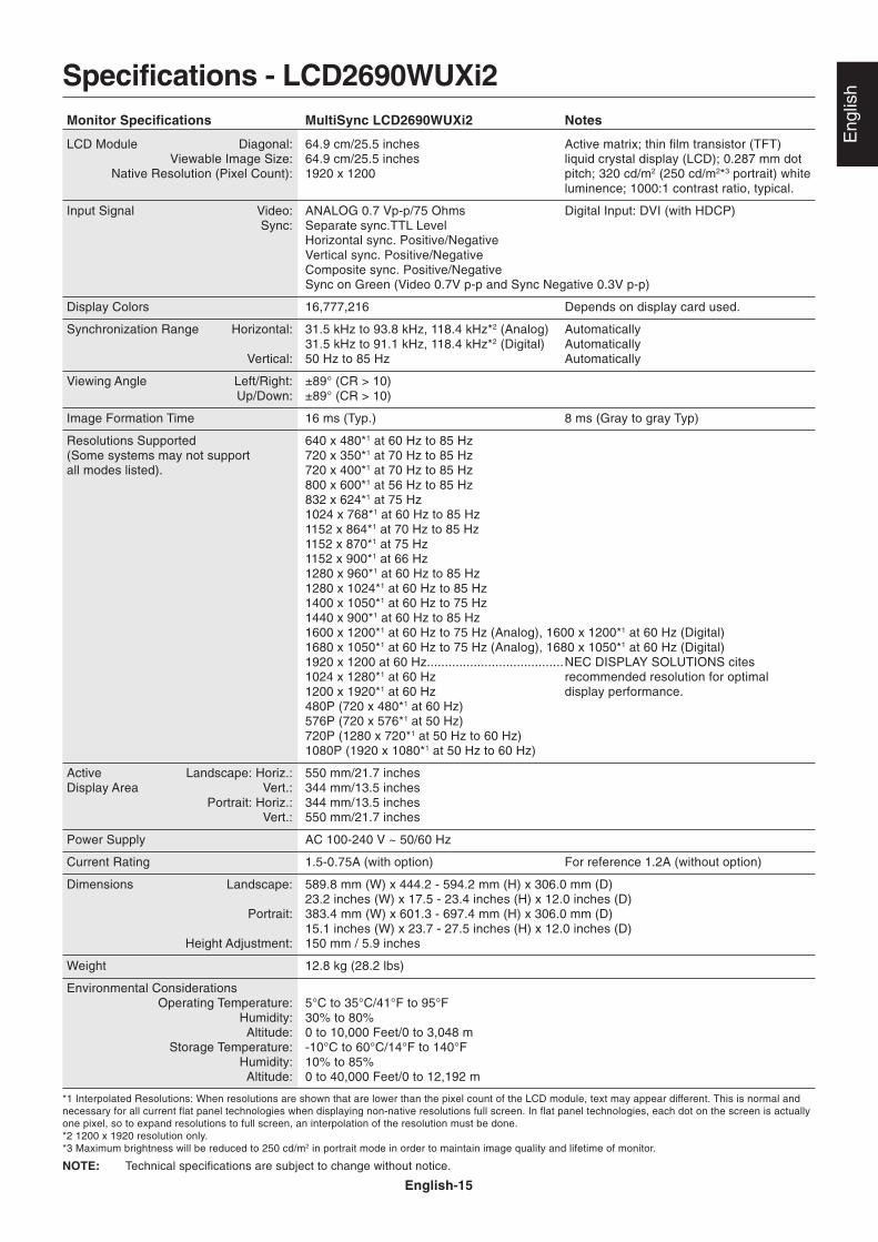
lishSpecifications - LCD2690WUXi2
Monitor Specifications MultiSync LCD2690WUXi2 Notes
LCD Module Diagonal: 64.9 cm/25.5 inches Active matrix; thin film transistor (TFT)Viewable Image Size: 64.9 cm/25.5 inches liquid crystal display (LCD); 0.287 mm dot
Native Resolution (Pixel Count): 1920 x 1200 pitch; 320 cd/m2 (250 cd/m2*3 portrait) whiteluminence; 1000:1 contrast ratio, typical.
Input Signal Video: ANALOG 0.7 Vp-p/75 Ohms Digital Input: DVI (with HDCP)Sync: Separate sync.TTL Level
Horizontal sync. Positive/NegativeVertical sync. Positive/NegativeComposite sync. Positive/NegativeSync on Green (Video 0.7V p-p and Sync Negative 0.3V p-p)
Display Colors 16,777,216 Depends on display card used.
Synchronization Range Horizontal: 31.5 kHz to 93.8 kHz, 118.4 kHz*2 (Analog) Automatically31.5 kHz to 91.1 kHz, 118.4 kHz*2 (Digital) Automatically
Vertical: 50 Hz to 85 Hz Automatically
Viewing Angle Left/Right: ±89° (CR > 10)Up/Down: ±89° (CR > 10)
Image Formation Time 16 ms (Typ.) 8 ms (Gray to gray Typ)
Resolutions Supported 640 x 480*1 at 60 Hz to 85 Hz(Some systems may not support 720 x 350*1 at 70 Hz to 85 Hzall modes listed). 720 x 400*1 at 70 Hz to 85 Hz
800 x 600*1 at 56 Hz to 85 Hz832 x 624*1 at 75 Hz1024 x 768*1 at 60 Hz to 85 Hz1152 x 864*1 at 70 Hz to 85 Hz1152 x 870*1 at 75 Hz1152 x 900*1 at 66 Hz1280 x 960*1 at 60 Hz to 85 Hz1280 x 1024*1 at 60 Hz to 85 Hz1400 x 1050*1 at 60 Hz to 75 Hz1440 x 900*1 at 60 Hz to 85 Hz1600 x 1200*1 at 60 Hz to 75 Hz (Analog), 1600 x 1200*1 at 60 Hz (Digital)1680 x 1050*1 at 60 Hz to 75 Hz (Analog), 1680 x 1050*1 at 60 Hz (Digital)1920 x 1200 at 60 Hz......................................NEC DISPLAY SOLUTIONS cites1024 x 1280*1 at 60 Hz recommended resolution for optimal1200 x 1920*1 at 60 Hz display performance.480P (720 x 480*1 at 60 Hz)576P (720 x 576*1 at 50 Hz)720P (1280 x 720*1 at 50 Hz to 60 Hz)1080P (1920 x 1080*1 at 50 Hz to 60 Hz)
Active Landscape: Horiz.: 550 mm/21.7 inchesDisplay Area Vert.: 344 mm/13.5 inches
Portrait: Horiz.: 344 mm/13.5 inchesVert.: 550 mm/21.7 inches
Power Supply AC 100-240 V ~ 50/60 Hz
Current Rating 1.5-0.75A (with option) For reference 1.2A (without option)
Dimensions Landscape: 589.8 mm (W) x 444.2 - 594.2 mm (H) x 306.0 mm (D)23.2 inches (W) x 17.5 - 23.4 inches (H) x 12.0 inches (D)
Portrait: 383.4 mm (W) x 601.3 - 697.4 mm (H) x 306.0 mm (D)15.1 inches (W) x 23.7 - 27.5 inches (H) x 12.0 inches (D)
Height Adjustment: 150 mm / 5.9 inches
Weight 12.8 kg (28.2 lbs)
Environmental ConsiderationsOperating Temperature: 5°C to 35°C/41°F to 95°F
Humidity: 30% to 80%Altitude: 0 to 10,000 Feet/0 to 3,048 m
Storage Temperature: -10°C to 60°C/14°F to 140°FHumidity: 10% to 85%Altitude: 0 to 40,000 Feet/0 to 12,192 m
*1 Interpolated Resolutions: When resolutions are shown that are lower than the pixel count of the LCD module, text may appear different. This is normal andnecessary for all current flat panel technologies when displaying non-native resolutions full screen. In flat panel technologies, each dot on the screen is actuallyone pixel, so to expand resolutions to full screen, an interpolation of the resolution must be done.*2 1200 x 1920 resolution only.*3 Maximum brightness will be reduced to 250 cd/m2 in portrait mode in order to maintain image quality and lifetime of monitor.
NOTE: Technical specifications are subject to change without notice.
English-16
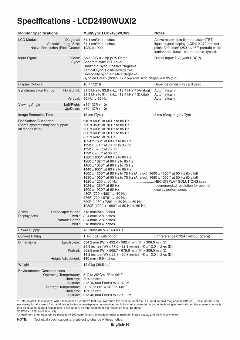
Specifications - LCD2490WUXi2Monitor Specifications MultiSync LCD2490WUXi2 Notes
LCD Module Diagonal: 61.1 cm/24.1 inches Active matrix; thin film transistor (TFT)Viewable Image Size: 61.1 cm/24.1 inches liquid crystal display (LCD); 0.270 mm dot
Native Resolution (Pixel Count): 1920 x 1200 pitch; 320 cd/m2 (250 cd/m2 *3 portrait) whiteluminence; 1000:1 contrast ratio, typical.
Input Signal Video: ANALOG 0.7 Vp-p/75 Ohms Digital Input: DVI (with HDCP)Sync: Separate sync.TTL Level
Horizontal sync. Positive/NegativeVertical sync. Positive/NegativeComposite sync. Positive/NegativeSync on Green (Video 0.7V p-p and Sync Negative 0.3V p-p)
Display Colours 16,777,216 Depends on display card used.
Synchronization Range Horizontal: 31.5 kHz to 93.8 kHz, 118.4 kHz*2 (Analog) Automatically31.5 kHz to 91.1 kHz, 118.4 kHz*2 (Digital) Automatically
Vertical: 50 Hz to 85 Hz Automatically
Viewing Angle Left/Right: ±89° (CR > 10)Up/Down: ±89° (CR > 10)
Image Formation Time 16 ms (Typ.) 8 ms (Gray to gray Typ)
Resolutions Supported 640 x 480*1 at 60 Hz to 85 Hz(Some systems may not support 720 x 350*1 at 70 Hz to 85 Hzall modes listed). 720 x 400*1 at 70 Hz to 85 Hz
800 x 600*1 at 56 Hz to 85 Hz832 x 624*1 at 75 Hz1024 x 768*1 at 60 Hz to 85 Hz1152 x 864*1 at 70 Hz to 85 Hz1152 x 870*1 at 75 Hz1152 x 900*1 at 66 Hz1280 x 960*1 at 60 Hz to 85 Hz1280 x 1024*1 at 60 Hz to 85 Hz1400 x 1050*1 at 60 Hz to 75 Hz1440 x 900*1 at 60 Hz to 85 Hz1600 x 1200*1 at 60 Hz to 75 Hz (Analog), 1600 x 1200*1 at 60 Hz (Digital)1680 x 1050*1 at 60 Hz to 75 Hz (Analog), 1680 x 1050*1 at 60 Hz (Digital)1920 x 1200 at 60 Hz......................................NEC DISPLAY SOLUTIONS cites1024 x 1280*1 at 60 Hz recommended resolution for optimal1200 x 1920*1 at 60 Hz display performance.480P (720 x 480*1 at 60 Hz)576P (720 x 576*1 at 50 Hz)720P (1280 x 720*1 at 50 Hz to 60 Hz)1080P (1920 x 1080*1 at 50 Hz to 60 Hz)
Active Landscape: Horiz.: 518 mm/20.4 inchesDisplay Area Vert.: 324 mm/12.8 inches
Portrait: Horiz.: 324 mm/12.8 inchesVert.: 518 mm/20.4 inches
Power Supply AC 100-240 V ~ 50/60 Hz
Current Rating 1.1-0.55A (with option) For reference 0.92A (without option)
Dimensions Landscape: 554.2 mm (W) x 432.4 - 582.4 mm (H) x 306.0 mm (D)21.8 inches (W) x 17.0 - 22.9 inches (H) x 12.0 inches (D)
Portrait: 359.8 mm (W) x 565.7 - 679.6 mm (H) x 306.0 mm (D)14.2 inches (W) x 22.3 - 26.8 inches (H) x 12.0 inches (D)
Height Adjustment: 150 mm / 5.9 inches
Weight 12.0 kg (26.5 lbs)
Environmental ConsiderationsOperating Temperature: 5°C to 35°C/41°F to 95°F
Humidity: 30% to 80%Altitude: 0 to 10,000 Feet/0 to 3,048 m
Storage Temperature: -10°C to 60°C/14°F to 140°FHumidity: 10% to 85%Altitude: 0 to 40,000 Feet/0 to 12,192 m
*1 Interpolated Resolutions: When resolutions are shown that are lower than the pixel count of the LCD module, text may appear different. This is normal andnecessary for all current flat panel technologies when displaying non-native resolutions full screen. In flat panel technologies, each dot on the screen is actuallyone pixel, so to expand resolutions to full screen, an interpolation of the resolution must be done.*2 1200 x 1920 resolution only.*3 Maximum brightness will be reduced to 250 cd/m2 in portrait mode in order to maintain image quality and lifetime of monitor.
NOTE: Technical specifications are subject to change without notice.
English-17
Eng
lishFeatures
Triple input technology: Triple input technology allowing up to 3 input sources to be connected to a single monitor. The DVI-I connectorsupports both analog and digital input signals. Legacy analog input is supported using a traditional 15-pin VGA connector. Triple inputtechnology provides traditional technology compatibility for analog as well as DVI-based digital compatibility for digital inputs. DVI-baseddigital interfaces include DVI-D, DFP and P&D.
DVI-I: The integrated interface ratified by the Digital Display Working Group (DDWG) that allows both digital and analog connectors off of oneport. The “I” stands for integration for both digital and analog, The digital portion is DVI-based.
DVI-D: The digital-only subset of DVI ratified by the Digital Display Working Group (DDWG) for digital connections between computers anddisplays. As a digital-only connector, analog support is not provided off a DVI-D connector. As a DVI-based digital only connection, only asimple adapter is necessary for compatibility between DVI-D and other DVI-based digital connectors such as DFP and P&D.
DFP (Digital Flat Panel): An all-digital interface for flat panel monitors which is signal compatible with DVI. As a DVI-based digital onlyconnection, only a simple adapter is necessary for compatibility between DFP and other DVI-based digital connectors such as DVI and P&D.
P&D (Plug and Display): The VESA standard for digital flat panel monitor interfaces. It is more robust than DFP since it allows for otheroptions off a signal connector (options like USB, analog video and IEEE-1394-995). The VESA committee has recognized that DFP is asubset of P&D. As a DVI-based connector (for the digital input pins), only a simple adapter is necessary for compatibility between P&D andother DVI-based digital connector such as DVI and DFP.
Pivoting Stand: Allows users to adjust the monitor to the orientation that best fits their application, either Landscape orientation for widedocuments, or Portrait orientation for the ability to preview a full page on one screen at one time. The Portrait orientation is also perfect forfull screen video conferencing.
Reduced Footprint: Provides the ideal solution for environments requiring superior image quality but with size and weight limitations. Themonitor’s small footprint and low weight allow it to be moved or transported easily from one location to another.
Color Control Systems: Allows you to adjust the colors on your screen and customize the color accuracy of your monitor to a variety ofstandards.
Natural Color Matrix: Combines Six-axis color control and the sRGB standard. Six-axis color control permits color adjustments via six axes(R, G, B, C, M and Y) rather than through the three axes (R, G and B) previously available. The sRGB standard provides the monitor with auniform color profile. This assures that the colors displayed on the monitor are exactly the same as on the color printout (with sRGBsupporting operating system and sRGB printer). This allows you to adjust the colors on your screen and customise the color accuracy of yourmonitor to a variety of standards.
OSD (On-Screen Display) Controls: Allow you to quickly and easily adjust all elements of your screen image via simple to use on-screenmenus.
ErgoDesign Features: Enhanced human ergonomics to improve the working environment, protect the health of the user and save money.Examples include OSD controls for quick and easy image adjustments, tilt base for preferred angle of vision, small footprint and compliancewith MPRII and TCO guidelines for lower emissions.
Plug and Play: The Microsoft® solution with the Windows® operating system facilitates setup and installation by allowing the monitor to sendits capabilities (such as screen size and resolutions supported) directly to your computer, automatically optimizing display performance.
Intelligent Power Manager System: Provides innovative power-saving methods that allow the monitor to shift to a lower power consumptionlevel when on but not in use, saving two-thirds of your monitor energy costs, reducing emissions and lowering the air conditioning costs ofthe workplace.
Multiple Frequency Technology: Automatically adjusts monitor to the display card’s scanning frequency, thus displaying the resolutionrequired.
FullScan Capability: Allows you to use the entire screen area in most resolutions, significantly expanding image size.
Wide Viewing Angle Technology: Allows the user to be able to see the monitor from any angle (178°) from any orientation — Portrait orLandscape. Provides full 178° viewing angles either up, down, left or right.
VESA Standard Mounting Interface: Allows users to connect their MultiSync monitor to any VESA standard third party mounting arm orbracket. Allows for the monitor to be mounted on a wall or an arm using any third party compliant device.
Visual Controller: Is a ground-breaking software family, developed by NEC Display Solutions Europe GmbH, providing intuitive access to allmonitor setting controls and remote diagnosis via the Windows interface, based upon the VESA standard, DDC/CI. Using a standard VGA orDVI signal cable, Visual Controller can either benefit single users or, with Visual Controller Administrator, can reduce the Total Cost ofOwnership through remote network-wide maintenance, diagnosis and asset-reporting.
Long cable capability automatic long cable compensation prevents image quality degradation caused by long cable lengths.
No-touch Auto Adjust (Analog input only): No-touch auto adjust automatically adjusts the monitor to optimal settings upon initial setup.
sRGB Color Control: A new optimized color management standard which allows for color matching on computer displays and otherperipherals. The sRGB, which is based on the calibrated color space, allows for optimal color representation and backward compatibility withother common color standards.
UNIFORMITY: This feature compensates for slight variations in the white uniformity level that may occur on the screen and improves thecolor and evens out the luminance uniformity of the display.
Response Improve: Improved gray to gray response.
Adjustable stand with pivot capability: Adds flexibility to your viewing preferences.
Quick Release stand: Allows fast removal.
Auto dimming technology: Automatically adjusts the backlight level depending on the level of ambient lighting.
English-18
TroubleshootingNo picture
• The signal cable should be completely connected to the display card/computer.
• The display card should be completely seated in its slot.
• Check the Vacation Switch should be in the ON position.
• Front Power Switch and computer power switch should be in the ON position.
• Check to make sure that a supported mode has been selected on the display card or system being used.(Please consult display card or system manual to change graphics mode.)
• Check the monitor and your display card with respect to compatibility and recommended settings.
• Check the signal cable connector for bent or pushed-in pins.
• Check the signal input, “DVI-D”, “DVI-I” or “D-Sub”.
• Ensure the DVI input mode is set to DIGITAL when the MAC digital output is connected to the DVI-I connector.
• If the front LED is blinking amber, check the status of the OFF MODE mode (see page 11).
• When using a DVD player or any other type of high-definition device, please do not use interlaced signals. If the monitordetects an interlaced signal, an OSD warning will appear. If this OSD warning appears, please do the following: press theRESET and EXIT buttons simultaneously, to temporarily show the image coming from the high-definition device. While theimage is visible, change the signal of the device from interlaced to progressive (non-interlaced). Consult the User's Manualincluded with the device for detailed information on changing the signal from interlaced to progressive.
Power Button does not respond• Unplug the power cord of the monitor from the AC outlet to turn off and reset the monitor.
• Check the Vacation Switch on the left side of the monitor.
Image Persistence• Image persistence is when a residual or “ghost” image of a previous image remains visible on the screen. Unlike CRT
monitors, LCD monitors’ image persistence is not permanent, but constant images being displayed for a long period oftime should be avoided. To alleviate image persistence, turn off the monitor for as long as the previous image wasdisplayed. For example, if an image was on the monitor for one hour and a residual image remains, the monitor shouldbe turned off for one hour to erase the image.
NOTE: As with all personal display devices, NEC DISPLAY SOLUTIONS recommends using a moving screen saver at regularintervals whenever the screen is idle or turning off the monitor when not in use.
Message “OUT OF RANGE” is displayed (screen is either blank or shows rough images only)• Image is displayed only roughly (pixels are missing) and OSD warning “OUT OF RANGE” is displayed: Either signal clock
or resolution is too high. Choose one of the supported modes.
• OSD warning “OUT OF RANGE” is displayed on a blank screen: Signal frequency is out of range. Choose one of thesupported modes.
Image is unstable, unfocused or swimming is apparent• Signal cable should be completely attached to the computer.
• Use the OSD Image Adjust controls to focus and adjust display by increasing or decreasing the fine adjustment.When the display mode is changed, the OSD Image Adjust settings may need to be readjusted.
• Check the monitor and your display card with respect to compatibility and recommended signal timings.
• If your text is garbled, change the video mode to non-interlace and use 60Hz refresh rate.
LED on monitor is not lit (no green, blue or amber color can be seen)• Power Switch should be in the ON position and power cord should be connected.
Picture is not as bright• Make sure ECO MODE, AUTO BRIGHTNESS, and UNIFORMITY are turned off.
• If the brightness fluctuates make sure AUTO BRIGHTNESS is turned off.
Display image is not sized properly• Use the OSD Image Adjust controls to increase or decrease the Coarse adjustment.
• Check to make sure that a supported mode has been selected on the display card or system being used.(Please consult display card or system manual to change graphics mode.)
No Video• If no video is present on the screen, turn the Power button off and on again.
• Make certain the computer is not in a power-saving mode (touch the keyboard or mouse).
• If no video is present on the screen, check the status of the EDID EXTENSION in the User menu (see page 11), the settingmay need to be changed to allow HDCP content to be displayed.
Self Diagnosis• The LCD display is equipped with the ability to self diagnose abnormalities. When the LCD detects a problem, the LED on
the front flashes in a pattern of long and short blinks, depending on the type of problem detected.
• If the LED detects a problem, please refer service to qualified personnel.
English-19
Eng
lishAdvanced OSD
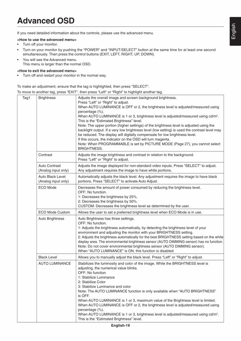
If you need detailed information about the controls, please use the advanced menu.
<How to use the advanced menu>• Turn off your monitor.
• Turn on your monitor by pushing the “POWER” and “INPUT/SELECT” button at the same time for at least one secondsimultaneously. Then press the control buttons (EXIT, LEFT, RIGHT, UP, DOWN).
• You will see the Advanced menu.This menu is larger than the normal OSD.
<How to exit the advanced menu>• Turn off and restart your monitor in the normal way.
To make an adjustment, ensure that the tag is highlighted, then press “SELECT”.
To move to another tag, press “EXIT”, then press “Left” or “Right” to highlight another tag.
Tag1 Brightness Adjusts the overall image and screen background brightness.Press “Left” or “Right” to adjust.When AUTO LUMINANCE is OFF or 2, the brightness level is adjusted/measured usingpercentage (%).When AUTO LUMINANCE is 1 or 3, brightness level is adjusted/measured using cd/m2.This is the “Estimated Brightness” level.Note: The upper portion (higher settings) of the brightness level is adjusted using thebacklight output. If a very low brightness level (low setting) is used the contrast level maybe reduced. The display will digitally compensate for low brightness level.If this occurs, the indicator on the OSD will turn magenta.Note: When PROGRAMMABLE is set by PICTURE MODE (Page 27), you cannot selectBRIGHTNESS.
Contrast Adjusts the image brightness and contrast in relation to the background.Press “Left” or “Right” to adjust.
Auto Contrast Adjusts the image displayed for non-standard video inputs. Press “SELECT” to adjust.(Analog input only) Any adjustment requires the image to have white portions.
Auto Black Level Automatically adjusts the black level. Any adjustment requires the image to have black(Analog input only) portions. Press “SELECT” to activate Auto Adjust.
ECO Mode Decreases the amount of power consumed by reducing the brightness level.OFF: No function.1: Decreases the brightness by 25%.2: Decreases the brightness by 50%.CUSTOM: Decreases the brightness level as determined by the user.
ECO Mode Custom Allows the user to set a preferred brightness level when ECO Mode is in use.
Auto Brightness Auto Brightness has three settings.OFF: No function.1: Adjusts the brightness automatically, by detecting the brightness level of yourenvironment and adjusting the monitor with your BRIGHTNESS setting.2: Adjusts the brightness automatically for the best BRIGHTNESS setting based on the whitedisplay area. The environmental brightness sensor (AUTO DIMMING sensor) has no function.Note: Do not cover environmental brightness sensor (AUTO DIMMING sensor).When “AUTO LUMINANCE” is ON, this function is disabled.
Black Level Allows you to manually adjust the black level. Press “Left” or “Right” to adjust.
AUTO LUMINANCE Stabilizes the luminosity and color of the image. While the BRIGHTNESS level isadjusting, the numerical value blinks.OFF: No function1: Stabilize Luminance2: Stabilize Color3: Stabilize Luminance and colorNote: The AUTO LUMINANCE function is only available when “AUTO BRIGHTNESS”is OFF.When AUTO LUMINANCE is 1 or 3, maximum value of the Brightness level is limited.When AUTO LUMINANCE is OFF or 2, the brightness level is adjusted/measured usingpercentage (%).When AUTO LUMINANCE is 1 or 3, brightness level is adjusted/measured using cd/m2.This is the “Estimated Brightness” level.
English-20
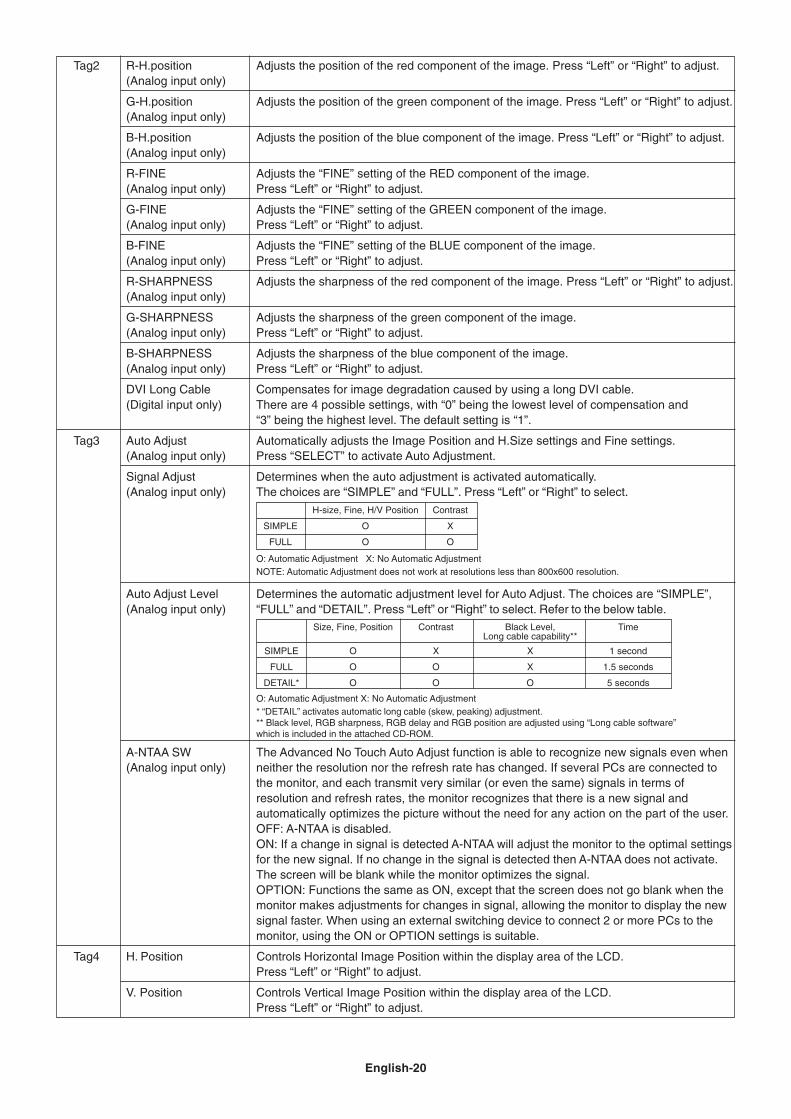
Tag2 R-H.position Adjusts the position of the red component of the image. Press “Left” or “Right” to adjust.(Analog input only)
G-H.position Adjusts the position of the green component of the image. Press “Left” or “Right” to adjust.(Analog input only)
B-H.position Adjusts the position of the blue component of the image. Press “Left” or “Right” to adjust.(Analog input only)
R-FINE Adjusts the “FINE” setting of the RED component of the image.(Analog input only) Press “Left” or “Right” to adjust.
G-FINE Adjusts the “FINE” setting of the GREEN component of the image.(Analog input only) Press “Left” or “Right” to adjust.
B-FINE Adjusts the “FINE” setting of the BLUE component of the image.(Analog input only) Press “Left” or “Right” to adjust.
R-SHARPNESS Adjusts the sharpness of the red component of the image. Press “Left” or “Right” to adjust.(Analog input only)
G-SHARPNESS Adjusts the sharpness of the green component of the image.(Analog input only) Press “Left” or “Right” to adjust.
B-SHARPNESS Adjusts the sharpness of the blue component of the image.(Analog input only) Press “Left” or “Right” to adjust.
DVI Long Cable Compensates for image degradation caused by using a long DVI cable.(Digital input only) There are 4 possible settings, with “0” being the lowest level of compensation and
“3” being the highest level. The default setting is “1”.
Tag3 Auto Adjust Automatically adjusts the Image Position and H.Size settings and Fine settings.(Analog input only) Press “SELECT” to activate Auto Adjustment.
Signal Adjust Determines when the auto adjustment is activated automatically.(Analog input only) The choices are “SIMPLE” and “FULL”. Press “Left” or “Right” to select.
Auto Adjust Level Determines the automatic adjustment level for Auto Adjust. The choices are “SIMPLE”,(Analog input only) “FULL” and “DETAIL”. Press “Left” or “Right” to select. Refer to the below table.
A-NTAA SW The Advanced No Touch Auto Adjust function is able to recognize new signals even when(Analog input only) neither the resolution nor the refresh rate has changed. If several PCs are connected to
the monitor, and each transmit very similar (or even the same) signals in terms ofresolution and refresh rates, the monitor recognizes that there is a new signal andautomatically optimizes the picture without the need for any action on the part of the user.OFF: A-NTAA is disabled.ON: If a change in signal is detected A-NTAA will adjust the monitor to the optimal settingsfor the new signal. If no change in the signal is detected then A-NTAA does not activate.The screen will be blank while the monitor optimizes the signal.OPTION: Functions the same as ON, except that the screen does not go blank when themonitor makes adjustments for changes in signal, allowing the monitor to display the newsignal faster. When using an external switching device to connect 2 or more PCs to themonitor, using the ON or OPTION settings is suitable.
Tag4 H. Position Controls Horizontal Image Position within the display area of the LCD.Press “Left” or “Right” to adjust.
V. Position Controls Vertical Image Position within the display area of the LCD.Press “Left” or “Right” to adjust.
H-size, Fine, H/V Position Contrast
SIMPLE O X
FULL O O
O: Automatic Adjustment X: No Automatic AdjustmentNOTE: Automatic Adjustment does not work at resolutions less than 800x600 resolution.
Size, Fine, Position Contrast Black Level, TimeLong cable capability**
SIMPLE O X X 1 second
FULL O O X 1.5 seconds
DETAIL* O O O 5 seconds
O: Automatic Adjustment X: No Automatic Adjustment* “DETAIL” activates automatic long cable (skew, peaking) adjustment.** Black level, RGB sharpness, RGB delay and RGB position are adjusted using “Long cable software”which is included in the attached CD-ROM.
English-21
Eng
lish
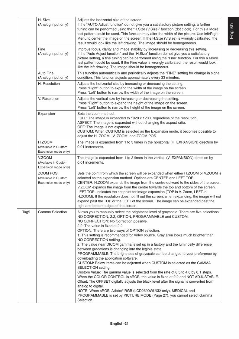
H. Size Adjusts the horizontal size of the screen.(Analog input only) If the “AUTO Adjust function” do not give you a satisfactory picture setting, a further
tuning can be performed using the “H.Size (V.Size)” function (dot clock). For this a Moirétest pattern could be used. This function may alter the width of the picture. Use left/RightMenu to center the image on the screen. If the H.Size (V.Size) is wrongly calibrated, theresult would look like the left drawing. The image should be homogeneous.
Fine Improve focus, clarity and image stability by increasing or decreasing this setting.(Analog input only) If the “Auto Adjust function” and the “H.Size” function do not give you a satisfactory
picture setting, a fine tuning can be performed using the “Fine” function. For this a Moirétest pattern could be used. If the Fine value is wrongly calibrated, the result would looklike the left drawing. The image should be homogeneous.
Auto Fine This function automatically and periodically adjusts the “FINE” setting for change in signal(Analog input only) condition. This function adjusts approximately every 33 minutes.
H. Resolution Adjusts the horizontal size by increasing or decreasing the setting.Press “Right” button to expand the width of the image on the screen.Press “Left” button to narrow the width of the image on the screen.
V. Resolution Adjusts the vertical size by increasing or decreasing the setting.Press “Right” button to expand the height of the image on the screen.Press “Left” button to narrow the height of the image on the screen.
Expansion Sets the zoom method.FULL: The image is expanded to 1920 x 1200, regardless of the resolution.ASPECT: The image is expanded without changing the aspect ratio.OFF: The image is not expanded.CUSTOM: When CUSTOM is selected as the Expansion mode, it becomes possible toadjust the H. ZOOM., V. ZOOM, and ZOOM POS.
H.ZOOM The image is expanded from 1 to 3 times in the horizontal (H. EXPANSION) direction by(Available in Custom 0.01 increments.Expansion mode only)
V.ZOOM The image is expanded from 1 to 3 times in the vertical (V. EXPANSION) direction by(Available in Custom 0.01 increments.Expansion mode only)
ZOOM POS. Sets the point from which the screen will be expanded when either H.ZOOM or V.ZOOM is(Available in Custom selected as the expansion method. Options are CENTER and LEFT TOP.Expansion mode only) CENTER: H.ZOOM expands the image from the centre outward to the sides of the screen.
V.ZOOM expands the image from the centre towards the top and bottom of the screen.LEFT TOP: Indicates the set point for image expansion (TOP in V. Zoom, LEFT inH.ZOOM). If the resolution does not fill out the screen, when expanding, the image will notexpand past the TOP or the LEFT of the screen. The image can be expanded past theright and bottom edges of the screen.
Tag5 Gamma Selection Allows you to manually select the brightness level of grayscale. There are five selections:NO CORRECTION, 2.2, OPTION, PROGRAMMABLE and CUSTOM.NO CORRECTION: No Correction possible.2.2: The value is fixed at 2.2.OPTION: There are two ways of OPTION selection.1: This setting is recommended for Video source. Gray area looks much brighter thanNO CORRECTION setting.2: The value near DICOM gamma is set up in a factory and the luminosity differencebetween gradations is changing into the legible state.PROGRAMMABLE: The brightness of grayscale can be changed to your preference bydownloading the application software.CUSTOM: Below items can be adjusted when CUSTOM is selected as the GAMMASELECTION setting.Custom Value: The gamma value is selected from the rate of 0.5 to 4.0 by 0.1 steps.When the COLOR CONTROL is sRGB, the value is fixed at 2.2 and NOT ADJUSTABLE.Offset: The OFFSET digitally adjusts the black level after the signal is converted fromanalog to digital.NOTE: When sRGB, Adobe® RGB (LCD2690WUXi2 only), MEDICAL andPROGRAMMABLE is set by PICTURE MODE (Page 27), you cannot select GammaSelection.
English-22
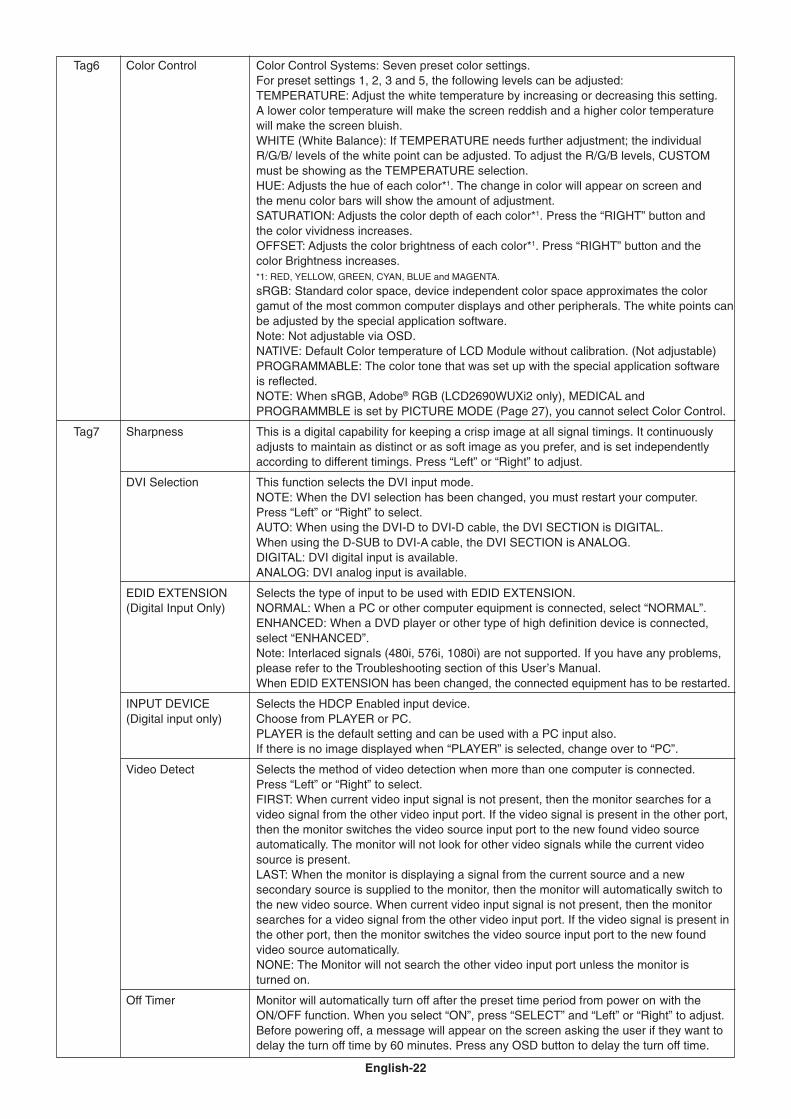
Tag6 Color Control Color Control Systems: Seven preset color settings.For preset settings 1, 2, 3 and 5, the following levels can be adjusted:TEMPERATURE: Adjust the white temperature by increasing or decreasing this setting.A lower color temperature will make the screen reddish and a higher color temperaturewill make the screen bluish.WHITE (White Balance): If TEMPERATURE needs further adjustment; the individualR/G/B/ levels of the white point can be adjusted. To adjust the R/G/B levels, CUSTOMmust be showing as the TEMPERATURE selection.HUE: Adjusts the hue of each color*1. The change in color will appear on screen andthe menu color bars will show the amount of adjustment.SATURATION: Adjusts the color depth of each color*1. Press the “RIGHT” button andthe color vividness increases.OFFSET: Adjusts the color brightness of each color*1. Press “RIGHT” button and thecolor Brightness increases.*1: RED, YELLOW, GREEN, CYAN, BLUE and MAGENTA.
sRGB: Standard color space, device independent color space approximates the colorgamut of the most common computer displays and other peripherals. The white points canbe adjusted by the special application software.Note: Not adjustable via OSD.NATIVE: Default Color temperature of LCD Module without calibration. (Not adjustable)PROGRAMMABLE: The color tone that was set up with the special application softwareis reflected.NOTE: When sRGB, Adobe® RGB (LCD2690WUXi2 only), MEDICAL andPROGRAMMBLE is set by PICTURE MODE (Page 27), you cannot select Color Control.
Tag7 Sharpness This is a digital capability for keeping a crisp image at all signal timings. It continuouslyadjusts to maintain as distinct or as soft image as you prefer, and is set independentlyaccording to different timings. Press “Left” or “Right” to adjust.
DVI Selection This function selects the DVI input mode.NOTE: When the DVI selection has been changed, you must restart your computer.Press “Left” or “Right” to select.AUTO: When using the DVI-D to DVI-D cable, the DVI SECTION is DIGITAL.When using the D-SUB to DVI-A cable, the DVI SECTION is ANALOG.DIGITAL: DVI digital input is available.ANALOG: DVI analog input is available.
EDID EXTENSION Selects the type of input to be used with EDID EXTENSION.(Digital Input Only) NORMAL: When a PC or other computer equipment is connected, select “NORMAL”.
ENHANCED: When a DVD player or other type of high definition device is connected,select “ENHANCED”.Note: Interlaced signals (480i, 576i, 1080i) are not supported. If you have any problems,please refer to the Troubleshooting section of this User’s Manual.When EDID EXTENSION has been changed, the connected equipment has to be restarted.
INPUT DEVICE Selects the HDCP Enabled input device.(Digital input only) Choose from PLAYER or PC.
PLAYER is the default setting and can be used with a PC input also.If there is no image displayed when “PLAYER” is selected, change over to “PC”.
Video Detect Selects the method of video detection when more than one computer is connected.Press “Left” or “Right” to select.FIRST: When current video input signal is not present, then the monitor searches for avideo signal from the other video input port. If the video signal is present in the other port,then the monitor switches the video source input port to the new found video sourceautomatically. The monitor will not look for other video signals while the current videosource is present.LAST: When the monitor is displaying a signal from the current source and a newsecondary source is supplied to the monitor, then the monitor will automatically switch tothe new video source. When current video input signal is not present, then the monitorsearches for a video signal from the other video input port. If the video signal is present inthe other port, then the monitor switches the video source input port to the new foundvideo source automatically.NONE: The Monitor will not search the other video input port unless the monitor isturned on.
Off Timer Monitor will automatically turn off after the preset time period from power on with theON/OFF function. When you select “ON”, press “SELECT” and “Left” or “Right” to adjust.Before powering off, a message will appear on the screen asking the user if they want todelay the turn off time by 60 minutes. Press any OSD button to delay the turn off time.
English-23
Eng
lish
OFF MODE The Intelligent Power Manager allows the monitor to enter into a power saving mode aftera period of inactivity. The OFF MODE has three settings.OFF: Monitor does not go into power save mode when the input signal is lost.STANDARD: Monitor enters power save mode automatically when the input signal is lost.OPTION: Monitor enters power save mode automatically when the amount of surroundinglight goes below the level that is determined by the user.
OFF MODE Setting Adjusts the ILLUMINANCE value for OFF MODE.
Response Improve Turns the Response Improve function on or off. Response Improve may reduce blurringthat occurs in some moving images. When Response Improve is on, response time isimproved.
Side Border Color Adjusts the side black bars color between black and white. For wide aspect monitors.
LED Brightness Controls the brightness of the LED on the monitor.
LED Color The LED on the front can be blue or green.
UNIFORMITY This function electronically compensates for the slight variations in the white uniformitylevel as well as for deviations in color that may occur throughout the display area of thescreen. These variations are characteristic of LCD panel technology. This functionimproves the color and evens out the luminance uniformity of the display.NOTE: Using the UNIFORMITY feature does reduce the overall peak luminance of thedisplay. If greater luminance is desired over the uniform performance of the display, thenUNIFORMITY should be turned off.
UNIFORMITY Level Select the level for UNIFORMITY adjustments.
Tag8 Language OSD control menus are available in eight languages. Press “Left” or “Right” to select.
OSD H. Position You can choose where you would like the OSD control image to appear on your screen.Selecting OSD Location allows you to manually adjust the position of the OSD controlmenu left or right.
OSD V. Position You can choose where you would like the OSD control image to appear on your screen.Selecting OSD Location allows you to manually adjust the position of the OSD controlmenu up or down.
OSD Turn off The OSD control menu will stay on as long as it is use. You can select how long themonitor waits after the last touch of a button to shut off the OSD control menu.The preset choices are 10-120 seconds by 5 seconds step.
OSD Lock Out This control completely locks out access to all OSD control functions. When attemptingto activate OSD controls while in the Lock Out mode, a screen will appear indicating theOSD controls are locked out.There are three types of OSD LOCK OUT:OSD LOCK OUT with BRIGHTNESS and CONTRAST control: To activate the OSD LockOut function, press SELECT, then “UP” button and hold down simultaneously. Todeactivate the OSD Lock Out, press SELECT, then “UP” button and hold downsimultaneously while in the OSD menu. BRIGHTNESS and CONTRAST can be adjustedwhile in the lock out mode.OSD LOCK OUT with no control: To activate the OSD Lock Out function, press SELECT,then “Right” button and hold down simultaneously. To deactivate the OSD Lock Out, pressSELECT, then “Right” button and hold down simultaneously while in the OSD menu.No controls can be adjusted while in the lock out mode.OSD LOCK OUT with BRIGHTNESS (only) control: To activate the OSD Lock Outfunction, press SELECT, then “Down” and “Left” buttons and hold down simultaneously.To deactivate the OSD Lock Out, press SELECT, then “Down” and “Left” buttons and holddown simultaneously while in the OSD menu. BRIGHTNESS can be adjusted while in thelock out mode.CUSTOM: Press RESET and EXIT to enter the CUSTOM Menu. Select ENABLE orDISABLE for POWER KEY, INPUT SEL, HOT KEY (BRIGHTNESS/CONTRAST), ECOMODE, WARNING (RESOLUTION NOTIFIER/OSD LOCK OUT). To Deactivate the OSDLock Out function, press RESET and EXIT to bring up the LOCK OUT warning.Press SELECT, SELECT, <, >, <, >, EXIT.
OSD Transparency Adjusts the transparency of the OSD MENU.
OSD Color “Tag window frame color”, “Item select color” & ”Adjust Window frame color” can be changed.
BOOT LOGO The NEC logo is briefly displayed after the monitor is powered on. This feature can beturned on or off in the OSD.Note: If the “EXIT” button is kept pressed while NEC logo is displayed, the BOOT LOGOmenu will appear. It is possible to change the BOOT LOGO setting to OFF.
English-24
Signal Information Signal information can be displayed in the corner of the screen.Signal information is either “On/Off”.
Resolution Notifier The optimal resolution is 1920 x 1200. If ON is selected, a message will appear on thescreen after 30 seconds, notifying you that the resolution is not set to 1920 x 1200.Press “Left” or “Right” to select.
Hot Key When this function is activated; the brightness and contrast of the monitor can be adjustedwithout entering the OSD menu by using the front buttons.The “Left” or “Right” buttons adjust the brightness level.The “Down” or “Up” buttons adjust the contrast level.
Factory Preset Selecting Factory Preset allows you to reset all OSD control settings back to the factorysettings. Highlighting the control to be reset and pressing the RESET button can resetindividual settings.
Tag9 Grayscale Mode This function changes the display image to monochrome.There are 3 types of settings.OFF: The Display Image is COLOR.MODE1: Input is R/G/B Color, but monitor uses only Green. The Display Image willbecome monochrome, because only green data passes the R/G/B LUT.MODE2: Input is R/G/B Color, but monitor changes the color space to YUV. The DisplayImage will become monochrome, because only Y data passes the R/G/B LUT.
OSD Rotation AUTO: The OSD rotates automatically when the monitor is rotated. OSD ROTATION isset to AUTO by default.LANDSCAPE: Display the OSD with landscape mode.PORTRAIT: Display the OSD with portrait mode.
Image Rotation AUTO: The display image automatically rotates according to the orientation of the OSD.If “AUTO” is selected in the “OSD ROTATION” menu, the display image rotates accordingto the orientation of the monitor.OFF: The display image is not rotated. IMAGE ROTATION is set to OFF by default.ON: The display image always rotated.
Portrait Warning When the monitor is used in the portrait position, the brightness value will be reduced to250 cd/m2. If the Portrait Warning is ON, a message will appear on the screen for 10 seconds.
DDC/CI DDC/CI ENABLE/DISABLE: Turns on or off the two way communication and control of themonitor.
Screen Saver Use the SCREEN SAVER to reduce the risk of image persistence.MOTION (Default OFF): Screen image moves periodically in 4 directions in order toreduce the risk of image retention.Timing for MOTION can be set so the screen image moves in intervals from every 10 to900 seconds. Timing is set in 10-second increments.OPTION (Default REDUCED): There are two optional selections.
REDUCED: Screen image is reduced to 95% size and is moved periodically in 4directions. Screen may appear slightly less sharp than normal. The full image appearson the display.NOTE: Some input signals may not be supported by REDUCED.FULL: Screen image is set to FULL and is moved periodically in 4 directions. Screenimage goes outside of the display area in the direction that it shifts so that a portion ofthe image may appear to be cut off.
GAMMA (Default OFF): When OFF, the GAMMA selection that the display uses is thesame as the GAMMA selection in Tag5 (page 21).When ON is selected, the GAMMA curve (except PROGRAMMABLE) becomes narrow,reducing the contrast and cutting down the risk of image retention.NOTE: SCREEN SAVER does not function when the TILE MATRIX function is enabled.
Input Setting Video Band Width (Analog input only): Reduce the visual “noise” level of the input signal.It is strong ineffective, so that a number becomes small. Press “Left” or “Right” to select.Sync Threshold (Analog input only): Adjusts the slice level of a synchronization signal.Press “SELECT” to move the adjustment menu. Adjusts the sensitivity of the separate orcomposite input signals.Try this option if the FINE adjustment does not successfully eliminate the noise.SOG Threshold (Analog input only): Adjusts the sensitivity of the Sync On Green inputsignals. Adjusts the slice level when separating synchronization from sync On Greensignal input. Press “Left” or “Right” to select.Clamp position: Operating your monitor at a non-standard timing may cause images toappear darker than normal or have color distortion. Use of the Clamp position control willadjust images to their normal state.
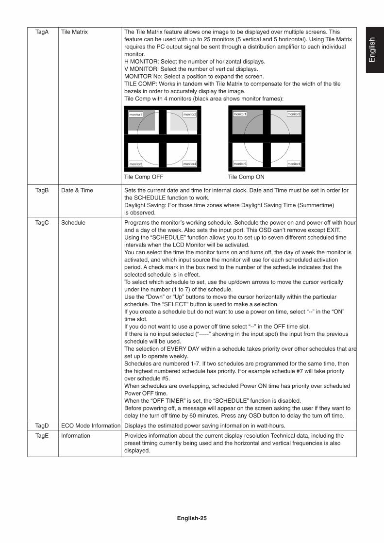
English-25
Eng
lish
TagA Tile Matrix The Tile Matrix feature allows one image to be displayed over multiple screens. Thisfeature can be used with up to 25 monitors (5 vertical and 5 horizontal). Using Tile Matrixrequires the PC output signal be sent through a distribution amplifier to each individualmonitor.H MONITOR: Select the number of horizontal displays.V MONITOR: Select the number of vertical displays.MONITOR No: Select a position to expand the screen.TILE COMP: Works in tandem with Tile Matrix to compensate for the width of the tilebezels in order to accurately display the image.Tile Comp with 4 monitors (black area shows monitor frames):
TagB Date & Time Sets the current date and time for internal clock. Date and Time must be set in order forthe SCHEDULE function to work.Daylight Saving: For those time zones where Daylight Saving Time (Summertime)is observed.
TagC Schedule Programs the monitor’s working schedule. Schedule the power on and power off with hourand a day of the week. Also sets the input port. This OSD can’t remove except EXIT.Using the “SCHEDULE” function allows you to set up to seven different scheduled timeintervals when the LCD Monitor will be activated.You can select the time the monitor turns on and turns off, the day of week the monitor isactivated, and which input source the monitor will use for each scheduled activationperiod. A check mark in the box next to the number of the schedule indicates that theselected schedule is in effect.To select which schedule to set, use the up/down arrows to move the cursor verticallyunder the number (1 to 7) of the schedule.Use the “Down” or “Up” buttons to move the cursor horizontally within the particularschedule. The “SELECT” button is used to make a selection.If you create a schedule but do not want to use a power on time, select “--” in the “ON”time slot.If you do not want to use a power off time select “--” in the OFF time slot.If there is no input selected (“-----” showing in the input spot) the input from the previousschedule will be used.The selection of EVERY DAY within a schedule takes priority over other schedules that areset up to operate weekly.Schedules are numbered 1-7. If two schedules are programmed for the same time, thenthe highest numbered schedule has priority. For example schedule #7 will take priorityover schedule #5.When schedules are overlapping, scheduled Power ON time has priority over scheduledPower OFF time.When the “OFF TIMER” is set, the “SCHEDULE” function is disabled.Before powering off, a message will appear on the screen asking the user if they want todelay the turn off time by 60 minutes. Press any OSD button to delay the turn off time.
TagD ECO Mode Information Displays the estimated power saving information in watt-hours.
TagE Information Provides information about the current display resolution Technical data, including thepreset timing currently being used and the horizontal and vertical frequencies is alsodisplayed.
monitor1 monitor2
monitor3 monitor4
monitor1 monitor2
monitor3 monitor4
Tile Comp ONTile Comp OFF
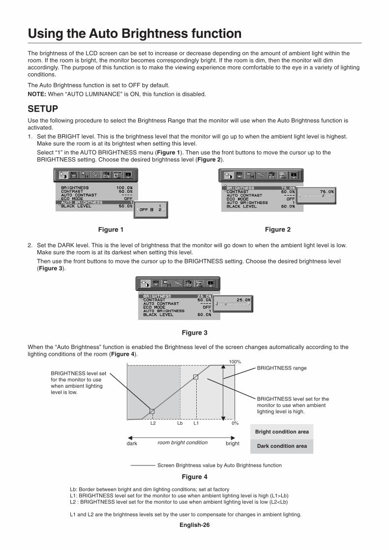
English-26
Using the Auto Brightness functionThe brightness of the LCD screen can be set to increase or decrease depending on the amount of ambient light within theroom. If the room is bright, the monitor becomes correspondingly bright. If the room is dim, then the monitor will dimaccordingly. The purpose of this function is to make the viewing experience more comfortable to the eye in a variety of lightingconditions.
The Auto Brightness function is set to OFF by default.
NOTE: When “AUTO LUMINANCE” is ON, this function is disabled.
SETUPUse the following procedure to select the Brightness Range that the monitor will use when the Auto Brightness function isactivated.
1. Set the BRIGHT level. This is the brightness level that the monitor will go up to when the ambient light level is highest.Make sure the room is at its brightest when setting this level.
Select “1” in the AUTO BRIGHTNESS menu (Figure 1). Then use the front buttons to move the cursor up to theBRIGHTNESS setting. Choose the desired brightness level (Figure 2).
2. Set the DARK level. This is the level of brightness that the monitor will go down to when the ambient light level is low.Make sure the room is at its darkest when setting this level.
Then use the front buttons to move the cursor up to the BRIGHTNESS setting. Choose the desired brightness level(Figure 3).
Figure 1 Figure 2
Figure 3
When the “Auto Brightness” function is enabled the Brightness level of the screen changes automatically according to thelighting conditions of the room (Figure 4).
BRIGHTNESS level setfor the monitor to usewhen ambient lightinglevel is low.
BRIGHTNESS level set for themonitor to use when ambientlighting level is high.
BRIGHTNESS range
Lb: Border between bright and dim lighting conditions; set at factoryL1: BRIGHTNESS level set for the monitor to use when ambient lighting level is high (L1>Lb)L2 : BRIGHTNESS level set for the monitor to use when ambient lighting level is low (L2<Lb)
L1 and L2 are the brightness levels set by the user to compensate for changes in ambient lighting.
Figure 4
dark brightroom bright condition
Screen Brightness value by Auto Brightness function
Bright condition area
Dark condition area
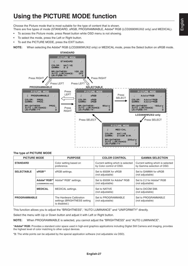
English-27
Eng
lishUsing the PICTURE MODE function
Choose the Picture mode that is most suitable for the type of content that is shown.There are five types of mode (STANDARD, sRGB, PROGRAMMABLE, Adobe® RGB (LCD2690WUXi2 only) and MEDICAL).
• To access the Picture mode, press Reset button while OSD menu is not showing.
• To select the mode, press the Left or Right button.
• To exit the PICTURE MODE, press the EXIT button.
NOTE: When selecting the Adobe® RGB (LCD2690WUXi2 only) or MEDICAL mode, press the Select button on sRGB mode.
PROGRAMMABLE
STANDARD
The type of PICTURE MODE
PICTURE MODE
STANDARD
SELECTABLE sRGB*2
Adobe® RGB*2
(LCD2690WUXi2 only)
MEDICAL
PROGRAMMABLE
PURPOSE
Color setting based onpreference.
sRGB settings.
Adobe® RGB* settings.
MEDICAL settings.
The Hardware Calibrationsettings (BRIGHTNESS settingis disabled.)
COLOR CONTROL
Current setting which is selectedby Color control of OSD.
Set to 6500K for sRGB(not adjustable)
Set to 6500K for Adobe® RGB(not adjustable)
Set to NATIVE(not adjustable)
Set to PROGRAMMABLE(not adjustable)
GAMMA SELECTION
Current setting which is selectedby Gamma selection of OSD.
Set to GAMMA for sRGB(not adjustable)
Set to 2.2 for Adobe® RGB(not adjustable)
Set to DICOM SIM.(not adjustable)
Set to PROGRAMMABLE(not adjustable)
This function allows you to adjust the “BRIGHTNESS”, “AUTO LUMINANCE” and “UNIFORMITY” directly.
Select the menu with Up or Down button and adjust it with Left or Right button.
NOTE: When PROGRAMMABLE is selected, you cannot adjust the “BRIGHTNESS” and “AUTO LUMINANCE”.
*Adobe® RGB: Provides a standard color space used in high-end graphics applications including Digital Still Camera and imaging, providesthe highest level of color matching to other output devices.
*2: The white points can be adjusted by the special application software (not adjustable via OSD).
PressSELECT
SELECTABLE
LCD2690WUXi2 only
Press SELECT
PressLEFT
PressRIGHT
Press RIGHT
Press SELECT
Press RIGHT
Press LEFT Press LEFT

English-28
TCO’03
Congratulations!The display you have just purchased carries the TCO’03 Displayslabel. This means that your display is designed, manufactured andtested according to some of the strictest quality and environmentalrequirements in the world. This makes for a high performanceproduct, designed with the user in focus that also minimizes theimpact on our natural environment.
Some of the features of the TCO’03 Display requirements:
Ergonomics• Good visual ergonomics and image quality in order to improve the working environment for
the user and to reduce sight and strain problems. Important parameters are luminance,contrast, resolution, reflectance, color rendition and image stability.
Energy• Energy-saving mode after a certain time – beneficial both for the user and the environment• Electrical safety
Emissions• Electromagnetic fields• Noise emissions
Ecology• The product must be prepared for recycling and the manufacturer must have a certified
environmental management system such as EMAS or ISO 14 001• Restrictions on:
- chlorinated and brominated flame retardants and polymers- heavy metals such as cadmium, mercury and lead.
The requirements included in this label have been developed by TCO Development in co-operation with scientists, experts, users as well as manufacturers all over the world. Since theend of the 1980s TCO has been involved in influencing the development of IT equipment in amore user-friendly direction. Our labelling system started with displays in 1992 and is nowrequested by users and IT-manufacturers all over the world.
For more information, please visitwww.tcodevelopment.com
English-29
Eng
lish
NEC DISPLAY SOLUTIONS is strongly committed to environmental protection and sees recycling as one of the company’stop priorities in trying to minimize the burden placed on the environment. We are engaged in developing environmentally-friendly products, and always strive to help define and comply with the latest independent standards from agencies such asISO (International Organisation for Standardization) and TCO (Swedish Trades Union).
Disposing of your old NEC productThe aim of recycling is to gain an environmental benefit by means of re-use, upgrading, reconditioning or reclamation ofmaterial. Dedicated recycling sites ensure that environmentally harmful components are properly handled and securelydisposed. To ensure the best recycling of our products, NEC DISPLAY SOLUTIONS offers a variety of recyclingprocedures and gives advice on how to handle the product in an environmentally sensitive way, once it has reached the endof its life.
All required information concerning the disposal of the product and country-specific information on recycling facilities can befound on our following websites:
http://www.nec-display-solutions.com/greencompany/ (in Europe),
http://www.nec-display.com (in Japan) or
http://www.necdisplay.com (in USA).
Energy SavingThis monitor features an advanced energy saving capability. When a VESA Display Power Management Signalling (DPMS)Standard signal is sent to the monitor, the Energy Saving mode is activated. The monitor enters a single Energy Saving mode.
Manufacturer’s Recycling and Energy Information
WEEE Mark (European Directive 2002/96/EC)Within the European Union
EU-wide legislation, as implemented in each Member State, requires that waste electrical and electronicproducts carrying the mark (left) must be disposed of separately from normal household waste. This includesmonitors and electrical accessories, such as signal cables or power cords. When you need to dispose of yourNEC display products, please follow the guidance of your local authority, or ask the shop where youpurchased the product, or if applicable, follow any agreements made between yourself and NEC.
The mark on electrical and electronic products only applies to the current European Union Member States.
Outside the European Union
If you wish to dispose of used electrical and electronic products outside the European Union, please contact your localauthority so as to comply with the correct disposal method.
Mode
Normal Operation (with option)
Normal Operation (at TCO testing)
Energy Saving Mode
Off Mode
Power consumption
Approx. 125W (LCD2690WUXi2)Approx. 89W (LCD2490WUXi2)
Approx. 65W
Less than 1W
Less than 1W
LED colour
Green or blue
Green or blue
Amber
Unlit