Embed Size (px)
Citation preview
10.07.13 Page 1 of 64
OVERVIEW ON UNDERWATER MUNITIONS TECHNOLOGY AND MYTHOLOGY FOR MILITARY
MUNITIONS RESPONSE PROGRAMS (MMRP’s)
1.0 INTRODUCTION
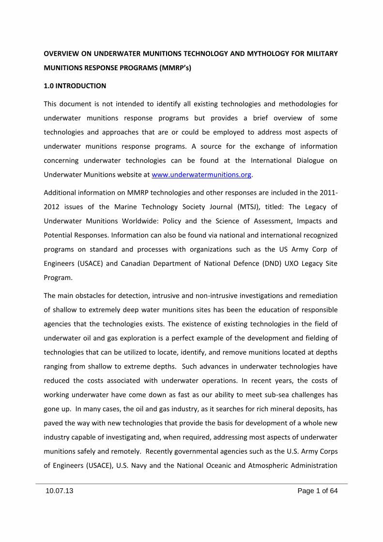
This document is not intended to identify all existing technologies and methodologies for
underwater munitions response programs but provides a brief overview of some
technologies and approaches that are or could be employed to address most aspects of
underwater munitions response programs. A source for the exchange of information
concerning underwater technologies can be found at the International Dialogue on
Underwater Munitions website at www.underwatermunitions.org.
Additional information on MMRP technologies and other responses are included in the 2011-
2012 issues of the Marine Technology Society Journal (MTSJ), titled: The Legacy of
Underwater Munitions Worldwide: Policy and the Science of Assessment, Impacts and
Potential Responses. Information can also be found via national and international recognized
programs on standard and processes with organizations such as the US Army Corp of
Engineers (USACE) and Canadian Department of National Defence (DND) UXO Legacy Site
Program.
The main obstacles for detection, intrusive and non-intrusive investigations and remediation
of shallow to extremely deep water munitions sites has been the education of responsible
agencies that the technologies exists. The existence of existing technologies in the field of
underwater oil and gas exploration is a perfect example of the development and fielding of
technologies that can be utilized to locate, identify, and remove munitions located at depths
ranging from shallow to extreme depths. Such advances in underwater technologies have
reduced the costs associated with underwater operations. In recent years, the costs of
working underwater have come down as fast as our ability to meet sub-sea challenges has
gone up. In many cases, the oil and gas industry, as it searches for rich mineral deposits, has
paved the way with new technologies that provide the basis for development of a whole new
industry capable of investigating and, when required, addressing most aspects of underwater
munitions safely and remotely. Recently governmental agencies such as the U.S. Army Corps
of Engineers (USACE), U.S. Navy and the National Oceanic and Atmospheric Administration
10.07.13 Page 2 of 64
(NOAA) in the United States and a wide assortment of governmental agencies in Europe and
Asia are now actively developing these technologies.
The ability to locate and conduct site characterization is an extremely important first step in
this process. The ability to accurately locate and characterize a site allows for accurate risk
assessment. The evaluation of the risk(s) is an important factor, since not all sites require will
remediation, but most will require risk mitigation planning. Technological advancements
have cleared the way for safe, environmentally friendly, and cost-effective remediation of
many of today’s sites, while some sites may not be likely candidates for remediation due to
environmental factors, risks, and high costs. Most importantly, detailed and updated
historical reviews, site sampling, risk identification and mitigation consideration are
necessary prior to any remediation of an underwater munitions site.
Technological advancements in the private sector have already demonstrated the ability to
conduct safe, cost efficient, non-destructive remediation of sea dumped munitions, including
their proper disposal. While there is no single technological approach to meeting challenges
found at every site, it is no longer correct to universally dismiss considering non-destructive
remediation for a lack of technology. There is no silver bullet that can address all aspects of
an underwater munitions response program; therefore one takes the “Tool Box Approach”;
whereas we reach into the toll box to select the right tool or a number of tools for the task at
hand.
2.0 MILITARY MUNITIONS RESPONSE PROGRAMS (MMRP’S)
MMRP programs are designed with emphasis on safety and control by implementing a strong
Project Management Plan that includes but not limited to: Project Management, Quality
Management Plan (Quality Controls - QC and Quality Assurances - QA), Safety Management
Plan (Health and Safety), Project Reporting and Project Close-out. These programs could be
models or guides for the future development of a country’s national munitions response
program.
To completely understand the development of a MMRP program, it requires codification of a
series of procedures and regulatory requirements. The Military Munitions Response Program
(MMRP) was established in September of 2001 by the Defense Environmental Restoration
10.07.13 Page 3 of 64
Program. It was established to identify and respond to environmental and explosive safety
hazards posed by Munitions and Explosives of Concern (MEC) and Munitions Constituents
(MC) at “surface” closed, transferred or transferring ranges. At the time that the MMRP was
established underwater sites were excluded and the U.S. Department of Defense (DoD)
refused to include underwater sites. Since 2001 gradually DoD has modified the rules
concerning what constitutes a Military Munitions Response Site under the Military Munitions
Response Program.
The current the United States DoD MMRP policy concerning underwater munitions response
sites states if the site is deeper than 120 ft (36.57m), it is not considered an underwater
munitions response site requiring remediation, and if the site is “dry” at low tide, then the
site is a terrestrial munitions response site. The current guidance also states a site cannot be
designated a munitions response site if the site is:
Part of, or associated with, a designated operational range (terrestrial or water)
A designated water disposal site
A Formerly Used Defense Site (FUDS)
A result of combat operations
A maritime wreck
An artificial reef
While the U.S. Military Munitions Response Program does provide a good working example,
it does present some constraints. It limits the depth of a site to 120 ft. (36.57m) and it does
not address disposal sites. There are also some questions regarding the exclusion of sites
involving combat operations and maritime wrecks. The development of a truly responsive
Munitions Response Program must address the concerns of both conventional and chemical
munitions, at all depths. It must also all inclusive, utilizing a risk based approach.
10.07.13 Page 4 of 64
2.1 Charter Document
One of the first steps in developing a MMRP is the charter document. The development of a
charter document must be scientifically comprehensive, and address the concerns of both
government agencies and the public.
Before a charter document can be developed, standardization of terminologies must be
achieved to enable a clear understanding of both technical terms and data. It is important
that all parties involved in the development of a MMRP charter document are able to use
terms that are readily identifiable and clearly understood. The development of a MMRP
charter document will require a multiple phase approach that includes a world-wide
inventory of underwater site locations and an acceptable remediation program that is risk
based.
2.2 Historical Review
Prior to commencing project activities a historical review should be carried out to determine
what has transpired in the study area in the pass to present day. Historical reviews are
conducted to gain a better understanding of what has transpired in order to better
understand project requirements such as scope, risk and approach.
Historical reviews are normally carry-out in two phases and are determine by the amount of
reliable and existing information available and the complexity of the site for the proposed
project. Historical reviews help stem the loss of information and can provide a guide or bases
to forum an understanding of what has
transpired at the site.
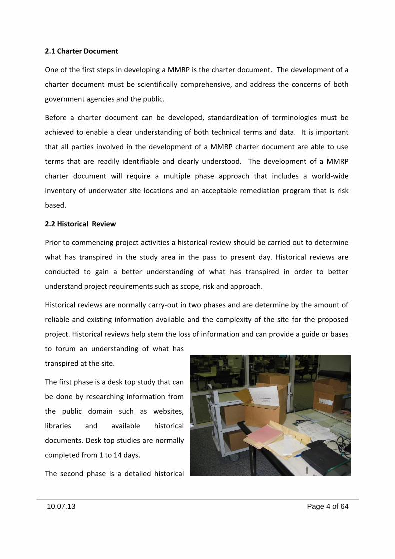
The first phase is a desk top study that can
be done by researching information from
the public domain such as websites,
libraries and available historical
documents. Desk top studies are normally
completed from 1 to 14 days.
The second phase is a detailed historical
10.07.13 Page 5 of 64
review that collects detailed information that will be used to develop a physical footprint for
a munitions response site. Access to military and government documents is essential to this
task and poses one of the hardest problem to overcome during any historical research. To
successfully accomplish any research effort governmental approval and support must be
established prior to any attempt to conduct a research project.
Once governmental approval is granted the next step is the development and staffing of the
research team. Ideally the team should consist of technically qualified personnel with
knowledge of munitions and a background in archive research techniques. Additionally
procedures such as the development of information search/recovery protocols must be
established prior to conducting the research. At a minimum a research team must have
laptop computers connected to flat screen digital scanners, with large screen capabilities.
3.0 PLATFORMS
There are a variety of surveying techniques for detecting underwater munitions. These tasks
can be accomplished from a variety of platforms. To some degree selection of the platform is
contingent on the nature of the task and the depth of the operation. The platforms include:
Divers
Underwater towed vehicles (UTV)
Autonomous underwater vehicles (AUV)
Remote operated vehicles (ROV)
Submersibles
However, those most commonly used in depths greater than 30.48 meters are towed or self
propelled vehicles to which sensors have been built in or attached. It is this variety that will
be addressed below. “The challenges of conducting an underwater munitions detection
survey include the properties of the water, the need to maintain safe working conditions, and
the ability to accurately locate and retrieve the detected items”. The ability to detect
underwater anomalies is at best a difficult undertaking, made more difficult as the depths
increase. The evolving dynamics of the oceans themselves must also be considered.
Underwater currents, marine growth and the effects of shifting bottom conditions only
10.07.13 Page 6 of 64
increase the problems one faces in trying to locate and recover material that has been
deposited on the ocean floor decades ago. No one tool or one particular method can be
successful in this effort. One can only view the efforts of the oil and gas exploration
corporations and various Oceanography institutes to understand this dilemma.
3.1 DIVING
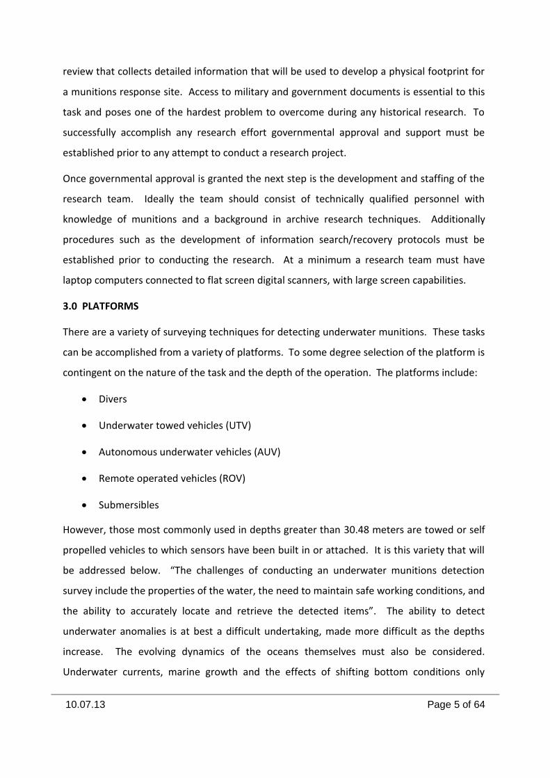
Divers may use either SCUBA (Self-Contained
Underwater Breathing Apparatus), supplied air
or one atmosphere suits. Each option has its
advantages an limitations, The greatest
concern associated with using divers in
munitions operations is their vulnerability
should an accident occur. Diving carries a
number of hazards in and of itself and the
danger from munitions is exacerbated underwater.
SCUBA divers can utilize either normal air or various gas mixtures. The use of normal
compressed air allows SCUBA divers a limited amount of time and depth. While using normal
air the diver is limited to approximately 30.48 meters and is limited to the amount of air that
he can carry. A surface supplied diver has an unlimited supply of air.
Mixed gas diving was developed to extend past the 0.8 meters limit and to extend divers time
on the bottom. TRIMIX and HELIOX systems extend the depth of the divers operational
capabilities beyond 50.29 meters. Divers are subject to the water temperature, pressure,
currents, and other environmental factors present at their diving depth. Work time varies
due to the pressures excreted and the dangers of decompression sickness (The Bends) if a
diver surfaces too fast. The use of NITROX and HELIOX reduces but does not eliminate the
danger. The normal operational limit for mixed gas dives is 91.44 meter. At that depth, the
bottom working time is limited to approximately 30-minutes.
At depths greater than 91.44 meters Saturation Diving is used which allows deeper dives and
more ambitious underwater tasks. Examples of saturation missions include submarine
10.07.13 Page 7 of 64
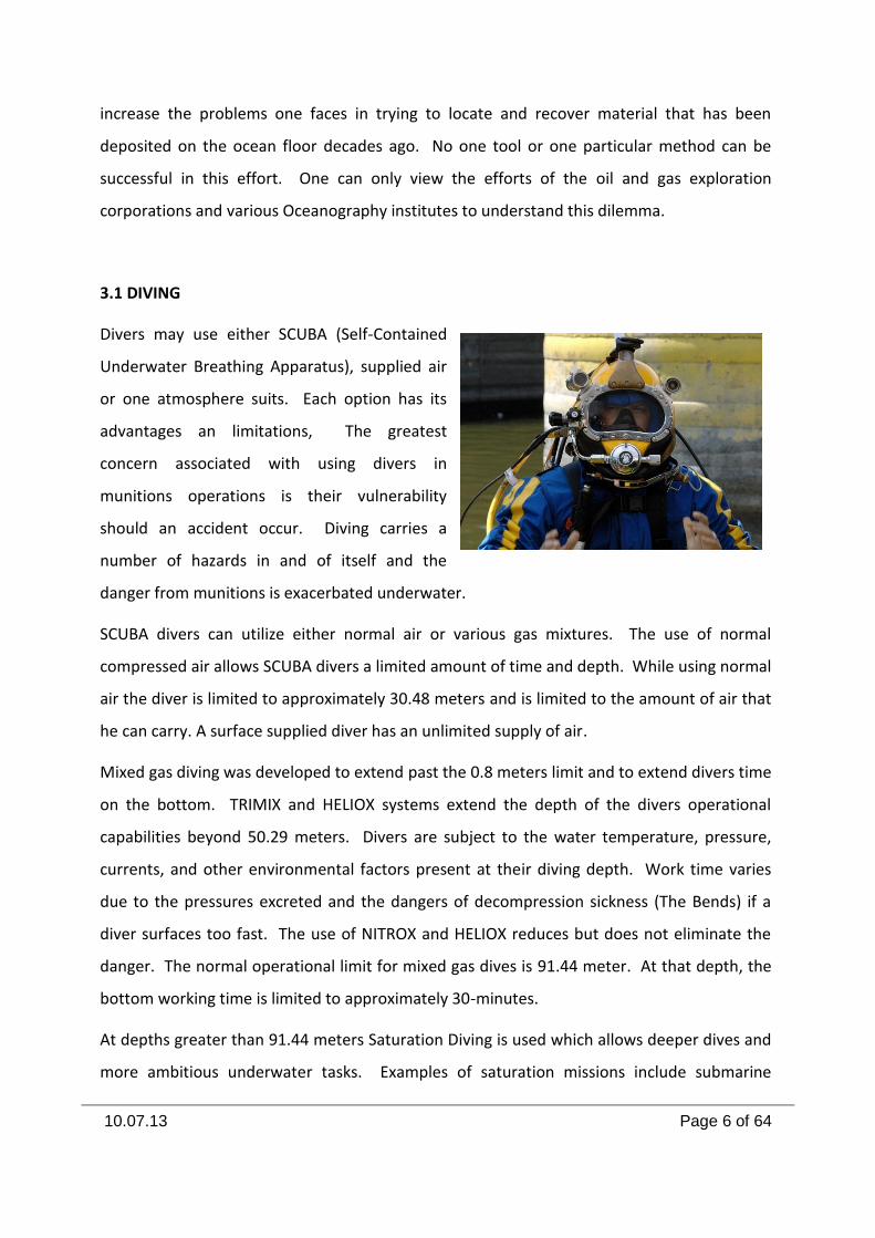
rescue and salvage, construction, and scientific testing
and observation. These types of operations are
characterized by the need for extensive bottom time
and, consequently, are more efficiently conducted using
saturation techniques. The identification and recovery
of munitions at depth beyond 91.44 meters would
require saturation divers operating from a Deep Diving
System (DDS). This system was developed to support
extended work time and deep depths for extended
periods of time. The commercial market for this technology is in the Ocean Oil & Gas
Industry.
The Deep Diving System consists of a Deck Decompression
Chamber (DDC) mounted on a surface-support ship. A
Personnel Transfer Capsule (PTC) is mated to the DDC, and
the combination is pressurized to a storage depth. Two or
more divers enter the PTC, which is unmated and lowered
to the working depth. The interior of the capsule is
pressurized to equal the pressure at depth, a hatch is
opened, and one or more divers swim out to accomplish
their work. Depths of up to 304.8 meters can be achieved
for extended periods of time.
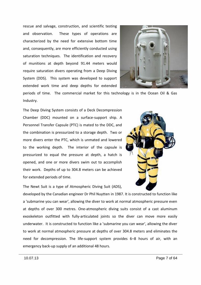
The Newt Suit is a type of Atmospheric Diving Suit (ADS),
developed by the Canadian engineer Dr Phil Nuytten in 1987. It is constructed to function like
a 'submarine you can wear', allowing the diver to work at normal atmospheric pressure even
at depths of over 300 metres. One-atmospheric diving suits consist of a cast aluminum
exoskeleton outfitted with fully-articulated joints so the diver can move more easily
underwater. It is constructed to function like a 'submarine you can wear', allowing the diver
to work at normal atmospheric pressure at depths of over 304.8 meters and eliminates the
need for decompression. The life-support system provides 6–8 hours of air, with an
emergency back-up supply of an additional 48 hours.
10.07.13 Page 8 of 64
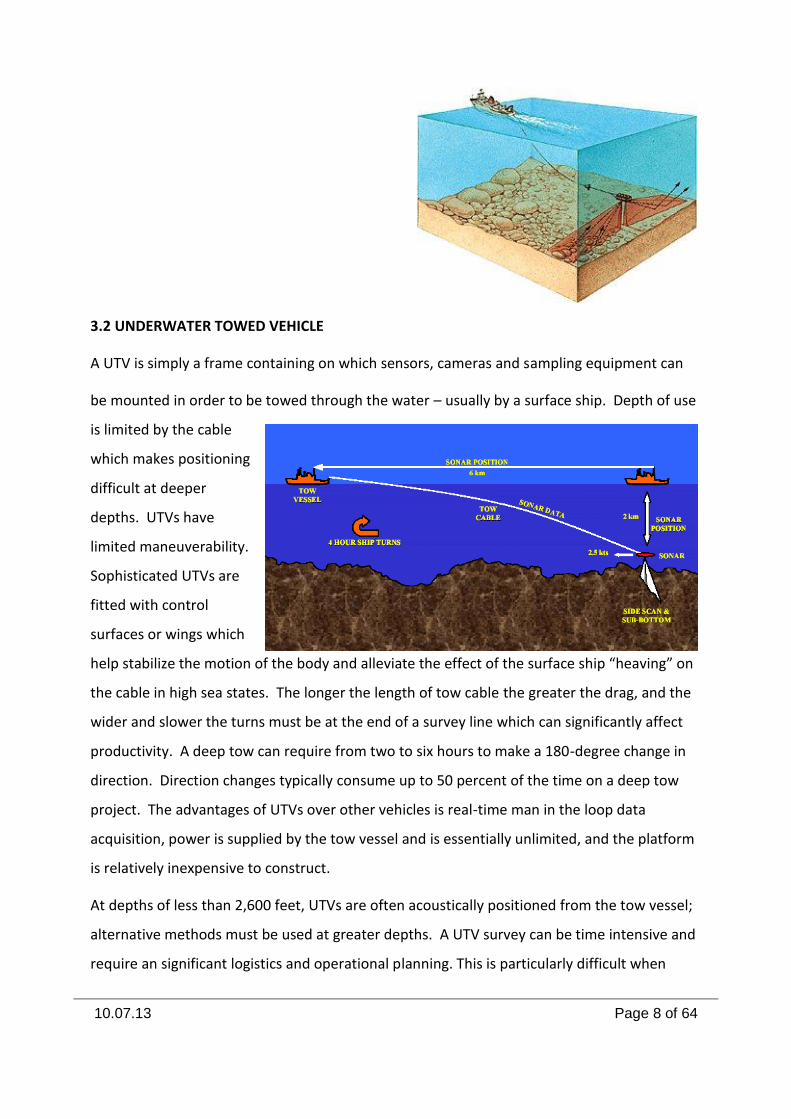
3.2 UNDERWATER TOWED VEHICLE
A UTV is simply a frame containing on which sensors, cameras and sampling equipment can
be mounted in order to be towed through the water – usually by a surface ship. Depth of use
is limited by the cable
which makes positioning
difficult at deeper
depths. UTVs have
limited maneuverability.
Sophisticated UTVs are
fitted with control
surfaces or wings which
help stabilize the motion of the body and alleviate the effect of the surface ship “heaving” on
the cable in high sea states. The longer the length of tow cable the greater the drag, and the
wider and slower the turns must be at the end of a survey line which can significantly affect
productivity. A deep tow can require from two to six hours to make a 180-degree change in
direction. Direction changes typically consume up to 50 percent of the time on a deep tow
project. The advantages of UTVs over other vehicles is real-time man in the loop data
acquisition, power is supplied by the tow vessel and is essentially unlimited, and the platform
is relatively inexpensive to construct.
At depths of less than 2,600 feet, UTVs are often acoustically positioned from the tow vessel;
alternative methods must be used at greater depths. A UTV survey can be time intensive and
require an significant logistics and operational planning. This is particularly difficult when
10.07.13 Page 9 of 64
using a deep tow in rough terrain. If the
deep tow is too high, data quality will be
poor. If the deep tow is too low, cross track
coverage is limited and the possibility of
colliding with the bottom becomes much
higher.
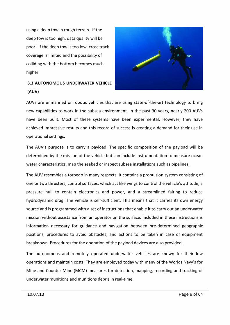
3.3 AUTONOMOUS UNDERWATER VEHICLE
(AUV)
AUVs are unmanned or robotic vehicles that are using state-of-the-art technology to bring
new capabilities to work in the subsea environment. In the past 30 years, nearly 200 AUVs
have been built. Most of these systems have been experimental. However, they have
achieved impressive results and this record of success is creating a demand for their use in
operational settings.
The AUV’s purpose is to carry a payload. The specific composition of the payload will be
determined by the mission of the vehicle but can include instrumentation to measure ocean
water characteristics, map the seabed or inspect subsea installations such as pipelines.
The AUV resembles a torpedo in many respects. It contains a propulsion system consisting of
one or two thrusters, control surfaces, which act like wings to control the vehicle’s attitude, a
pressure hull to contain electronics and power, and a streamlined fairing to reduce
hydrodynamic drag. The vehicle is self-sufficient. This means that it carries its own energy
source and is programmed with a set of instructions that enable it to carry out an underwater
mission without assistance from an operator on the surface. Included in these instructions is
information necessary for guidance and navigation between pre-determined geographic
positions, procedures to avoid obstacles, and actions to be taken in case of equipment
breakdown. Procedures for the operation of the payload devices are also provided.
The autonomous and remotely operated underwater vehicles are known for their low
operations and maintain costs. They are employed today with many of the Worlds Navy’s for
Mine and Counter-Mine (MCM) measures for detection, mapping, recording and tracking of
underwater munitions and munitions debris in real-time.
10.07.13 Page 10 of 64
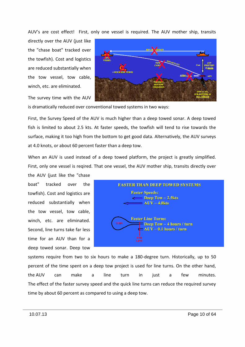
AUV’s are cost effect! First, only one vessel is required. The AUV mother ship, transits
directly over the AUV (just like
the "chase boat" tracked over
the towfish). Cost and logistics
are reduced substantially when
the tow vessel, tow cable,
winch, etc. are eliminated.
The survey time with the AUV
is dramatically reduced over conventional towed systems in two ways:
First, the Survey Speed of the AUV is much higher than a deep towed sonar. A deep towed
fish is limited to about 2.5 kts. At faster speeds, the towfish will tend to rise towards the
surface, making it too high from the bottom to get good data. Alternatively, the AUV surveys
at 4.0 knots, or about 60 percent faster than a deep tow.
When an AUV is used instead of a deep towed platform, the project is greatly simplified.
First, only one vessel is reqired. That one vessel, the AUV mother ship, transits directly over
the AUV (just like the "chase
boat" tracked over the
towfish). Cost and logistics are
reduced substantially when
the tow vessel, tow cable,
winch, etc. are eliminated.
Second, line turns take far less
time for an AUV than for a
deep towed sonar. Deep tow
systems require from two to six hours to make a 180-degree turn. Historically, up to 50
percent of the time spent on a deep tow project is used for line turns. On the other hand,
the AUV can make a line turn in just a few minutes.
The effect of the faster survey speed and the quick line turns can reduce the required survey
time by about 60 percent as compared to using a deep tow.
10.07.13 Page 11 of 64
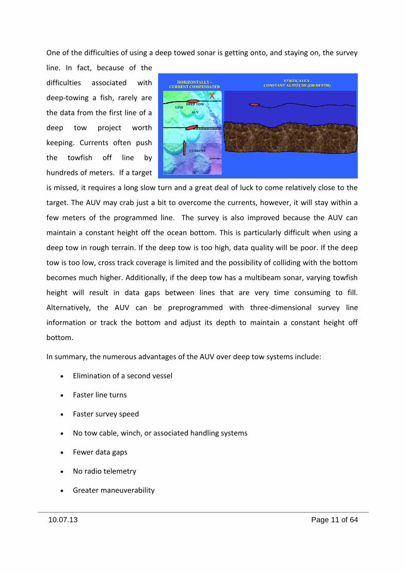
One of the difficulties of using a deep towed sonar is getting onto, and staying on, the survey
line. In fact, because of the
difficulties associated with
deep-towing a fish, rarely are
the data from the first line of a
deep tow project worth
keeping. Currents often push
the towfish off line by
hundreds of meters. If a target
is missed, it requires a long slow turn and a great deal of luck to come relatively close to the
target. The AUV may crab just a bit to overcome the currents, however, it will stay within a
few meters of the programmed line. The survey is also improved because the AUV can
maintain a constant height off the ocean bottom. This is particularly difficult when using a
deep tow in rough terrain. If the deep tow is too high, data quality will be poor. If the deep
tow is too low, cross track coverage is limited and the possibility of colliding with the bottom
becomes much higher. Additionally, if the deep tow has a multibeam sonar, varying towfish
height will result in data gaps between lines that are very time consuming to fill.
Alternatively, the AUV can be preprogrammed with three-dimensional survey line
information or track the bottom and adjust its depth to maintain a constant height off
bottom.
In summary, the numerous advantages of the AUV over deep tow systems include:
Elimination of a second vessel
Faster line turns
Faster survey speed
No tow cable, winch, or associated handling systems
Fewer data gaps
No radio telemetry
Greater maneuverability
10.07.13 Page 12 of 64
Terrain-following
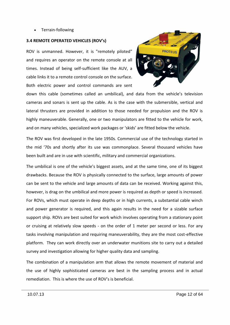
3.4 REMOTE OPERATED VEHICLES (ROV’s)
ROV is unmanned. However, it is "remotely piloted"
and requires an operator on the remote console at all
times. Instead of being self-sufficient like the AUV, a
cable links it to a remote control console on the surface.
Both electric power and control commands are sent
down this cable (sometimes called an umbilical), and data from the vehicle’s television
cameras and sonars is sent up the cable. As is the case with the submersible, vertical and
lateral thrusters are provided in addition to those needed for propulsion and the ROV is
highly maneuverable. Generally, one or two manipulators are fitted to the vehicle for work,
and on many vehicles, specialized work packages or ‘skids’ are fitted below the vehicle.
The ROV was first developed in the late 1950s. Commercial use of the technology started in
the mid ‘70s and shortly after its use was commonplace. Several thousand vehicles have
been built and are in use with scientific, military and commercial organizations.
The umbilical is one of the vehicle’s biggest assets, and at the same time, one of its biggest
drawbacks. Because the ROV is physically connected to the surface, large amounts of power
can be sent to the vehicle and large amounts of data can be received. Working against this,
however, is drag on the umbilical and more power is required as depth or speed is increased.
For ROVs, which must operate in deep depths or in high currents, a substantial cable winch
and power generator is required, and this again results in the need for a sizable surface
support ship. ROVs are best suited for work which involves operating from a stationary point
or cruising at relatively slow speeds - on the order of 1 meter per second or less. For any
tasks involving manipulation and requiring maneuverability, they are the most cost-effective
platform. They can work directly over an underwater munitions site to carry out a detailed
survey and investigation allowing for higher quality data and sampling.
The combination of a manipulation arm that allows the remote movement of material and
the use of highly sophisticated cameras are best in the sampling process and in actual
remediation. This is where the use of ROV’s is beneficial.
10.07.13 Page 13 of 64
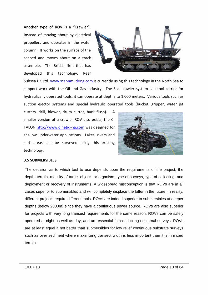
Another type of ROV is a “Crawler”.
Instead of moving about by electrical
propellers and operates in the water
column. It works on the surface of the
seabed and moves about on a track
assemble. The British firm that has
developed this technology, Reef
Subsea UK Ltd. www.scannmudring.com is currently using this technology in the North Sea to
support work with the Oil and Gas industry. The Scancrawler system is a tool carrier for
hydraulically operated tools, it can operate at depths to 1,000 meters. Various tools such as
suction ejector systems and special hydraulic operated tools (bucket, gripper, water jet
cutters, drill, blower, drum cutter, back flush). A
smaller version of a crawler ROV also exists, the C-
TALON http://www.qinetiq-na.com was designed for
shallow underwater applications. Lakes, rivers and
surf areas can be surveyed using this existing
technology.
3.5 SUBMERSIBLES
The decision as to which tool to use depends upon the requirements of the project, the
depth, terrain, mobility of target objects or organism, type of surveys, type of collecting, and
deployment or recovery of instruments. A widespread misconception is that ROVs are in all
cases superior to submersibles and will completely displace the latter in the future. In reality,
different projects require different tools. ROVs are indeed superior to submersibles at deeper
depths (below 2000m) since they have a continuous power source. ROVs are also superior
for projects with very long transect requirements for the same reason. ROVs can be safely
operated at night as well as day, and are essential for conducting nocturnal surveys. ROVs
are at least equal if not better than submersibles for low relief continuous substrate surveys
such as over sediment where maximizing transect width is less important than it is in mixed
terrain.
10.07.13 Page 14 of 64
However, submersibles with trained experienced observers can dramatically increase survey
swath widths and detection capabilities. The human eye is by far the most efficient visual
survey tool currently available. Submersibles with trained observers are significantly better at
surveying bottom features and munitions that are encrusted with marine growth.
Submersibles are far superior in extreme relief where concerns of snagging tethers are
significant. Submersible can sample on vertical and overhanging walls where many deep
water corals and sponges are
found and where ROV operators
are rarely willing to risk their
vehicles. Submersibles are
superior where maneuverability
is very important to the project.
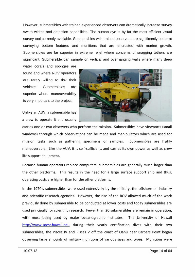
Unlike an AUV, a submersible has
a crew to operate it and usually
carries one or two observers who perform the mission. Submersibles have viewports (small
windows) through which observations can be made and manipulators which are used for
mission tasks such as gathering specimens or samples. Submersibles are highly
maneuverable. Like the AUV, it is self-sufficient, and carries its own power as well as crew
life support equipment.
Because human operators replace computers, submersibles are generally much larger than
the other platforms. This results in the need for a large surface support ship and thus,
operating costs are higher than for the other platforms.
In the 1970’s submersibles were used extensively by the military, the offshore oil industry
and scientific research agencies. However, the rise of the ROV allowed much of the work
previously done by submersible to be conducted at lower costs and today submersibles are
used principally for scientific research. Fewer than 20 submersibles are remain in operation,
with most being used by major oceanographic institutes. The University of Hawaii
http://www.soest.hawaii.edu during their yearly certification dives with their two
submersibles, the Pisces IV and Pisces V off the coast of Oahu near Barbers Point began
observing large amounts of military munitions of various sizes and types. Munitions were
10.07.13 Page 15 of 64
scattered along the entire length of a drop-off that reached 1,652 meters in depth. Attempts
were made to notify proper military authorities to no avail until newspaper articles in
October of 2005 brought to the attention to the public and U.S. Congress the fact that toxic
chemical munitions had been dumped in and around the Hawaiian Islands. At that time the
discoveries that had been made years ago became a point of serious concern by the U.S.
Department of Defense. The series of newspaper articles also spurred the U.S. Department
of Defense to begin a limited research effort to discover documents and records on where
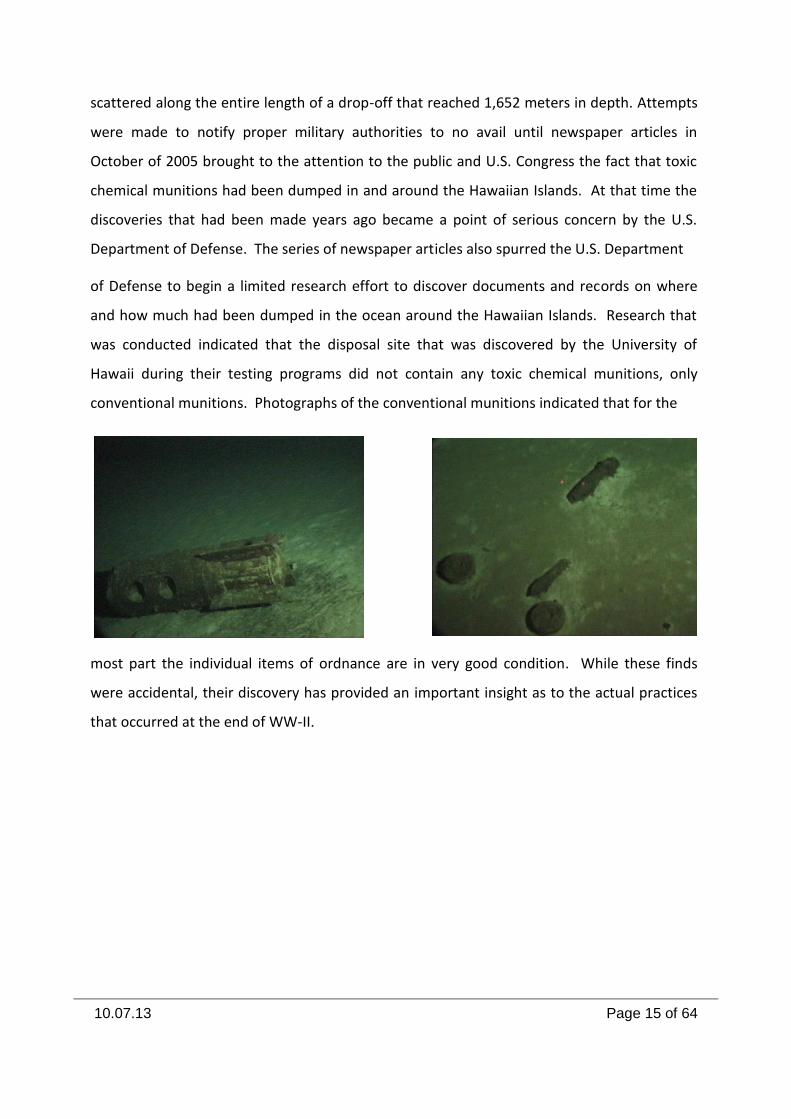
and how much had been dumped in the ocean around the Hawaiian Islands. Research that
was conducted indicated that the disposal site that was discovered by the University of
Hawaii during their testing programs did not contain any toxic chemical munitions, only
conventional munitions. Photographs of the conventional munitions indicated that for the
most part the individual items of ordnance are in very good condition. While these finds
were accidental, their discovery has provided an important insight as to the actual practices
that occurred at the end of WW-II.
10.07.13 Page 16 of 64
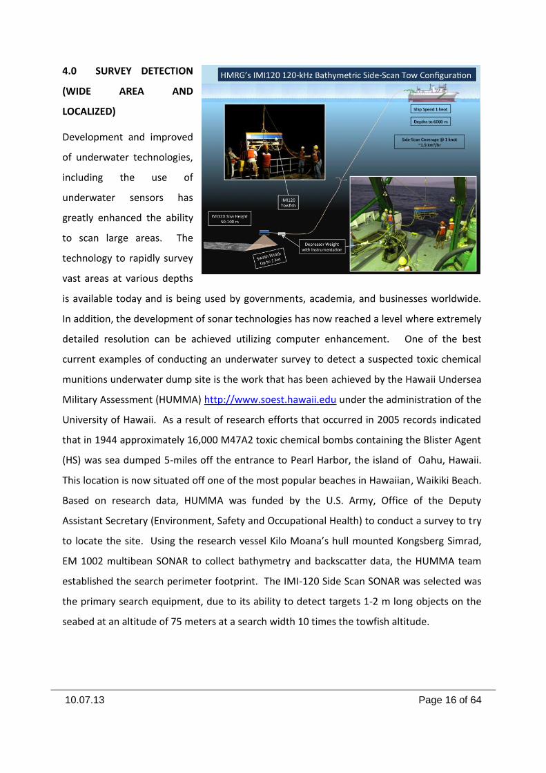
4.0 SURVEY DETECTION
(WIDE AREA AND
LOCALIZED)
Development and improved
of underwater technologies,
including the use of
underwater sensors has
greatly enhanced the ability
to scan large areas. The
technology to rapidly survey
vast areas at various depths
is available today and is being used by governments, academia, and businesses worldwide.
In addition, the development of sonar technologies has now reached a level where extremely
detailed resolution can be achieved utilizing computer enhancement. One of the best
current examples of conducting an underwater survey to detect a suspected toxic chemical
munitions underwater dump site is the work that has been achieved by the Hawaii Undersea
Military Assessment (HUMMA) http://www.soest.hawaii.edu under the administration of the
University of Hawaii. As a result of research efforts that occurred in 2005 records indicated
that in 1944 approximately 16,000 M47A2 toxic chemical bombs containing the Blister Agent
(HS) was sea dumped 5-miles off the entrance to Pearl Harbor, the island of Oahu, Hawaii.
This location is now situated off one of the most popular beaches in Hawaiian, Waikiki Beach.
Based on research data, HUMMA was funded by the U.S. Army, Office of the Deputy
Assistant Secretary (Environment, Safety and Occupational Health) to conduct a survey to try
to locate the site. Using the research vessel Kilo Moana’s hull mounted Kongsberg Simrad,
EM 1002 multibean SONAR to collect bathymetry and backscatter data, the HUMMA team
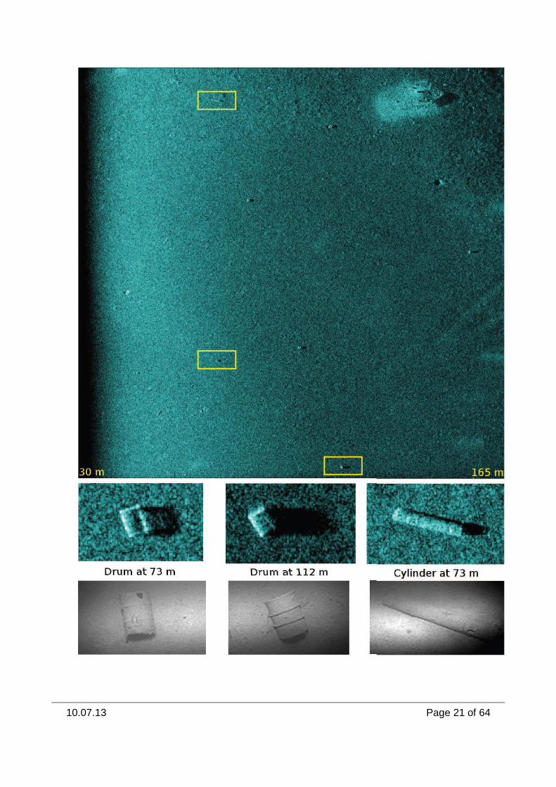
established the search perimeter footprint. The IMI-120 Side Scan SONAR was selected was
the primary search equipment, due to its ability to detect targets 1-2 m long objects on the
seabed at an altitude of 75 meters at a search width 10 times the towfish altitude.
10.07.13 Page 17 of 64
This combination of resolution and area coverage allowed 2.7km of seafloor to be mapped
per hour. The data collected allowed for a resolution of 0.25 meters, or approximately one
haft to one quarter the size of the smallest suspected targets. After completion of the survey
utilizing the IMI-120 SONAR, distinct linear patterns were detected that indicated that a
disposal action had taken place from a vessel that was in motion. The next phase of the
survey was conducted utilizing both ROV,s and their submersibles, Pisces IV and Pisces V.
Visual inspection of the debris fields confirmed that identifiable residue of M47A2 Chemical
Bombs and conventional munitions. This is an example of current technologies used in the
detection of munitions that was dumped at sea over 65 years ago.
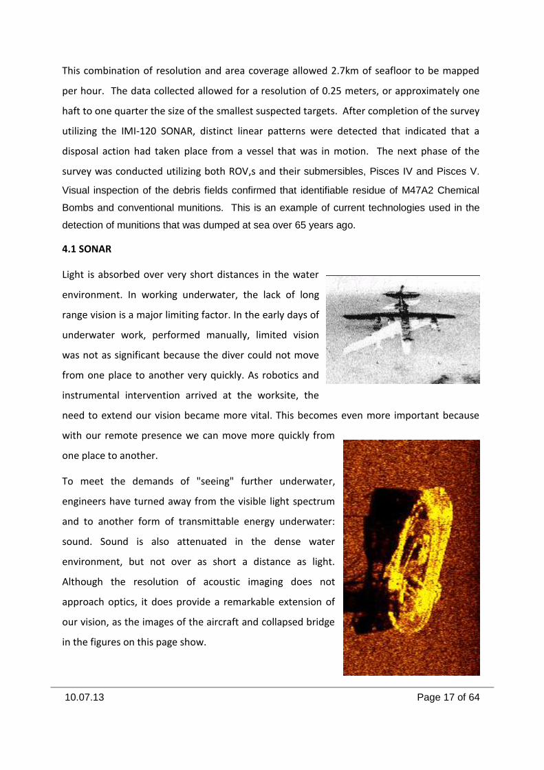
4.1 SONAR
Light is absorbed over very short distances in the water
environment. In working underwater, the lack of long
range vision is a major limiting factor. In the early days of
underwater work, performed manually, limited vision
was not as significant because the diver could not move
from one place to another very quickly. As robotics and
instrumental intervention arrived at the worksite, the
need to extend our vision became more vital. This becomes even more important because
with our remote presence we can move more quickly from
one place to another.
To meet the demands of "seeing" further underwater,
engineers have turned away from the visible light spectrum
and to another form of transmittable energy underwater:
sound. Sound is also attenuated in the dense water
environment, but not over as short a distance as light.
Although the resolution of acoustic imaging does not
approach optics, it does provide a remarkable extension of
our vision, as the images of the aircraft and collapsed bridge
in the figures on this page show.
10.07.13 Page 18 of 64
Those working underwater, including oceanographers, marine geologists, and ROV Pilots now
depend heavily on sound energy to transform the things we cannot see underwater into
numbers, graphs, and pictures. The ROV pilot in particular requires that the imaging sonar
provide him with accurate and quickly updated images. The instruments that transmit and
receive these sound pulses have become sophisticated and more accurate in the past few
decades.
Underwater, sound transmission is limited. This is most notable in useable ranges. High-
frequency sound energy is greatly reduced by seawater. Low-frequency sound energy is
reduced at a much lesser rate. For instance, a sound pulse of 50 Hertz can be transmitted
many thousands of kilometers in the ocean, but a pulse of 300 kHz, a common imaging sonar
frequency, can be transmitted less than 1,000 meters.
As applied to underwater vehicles, sonar systems in use today include mapping and collision
avoidance types. Side scan sonar transducers can be mounted on the sides of a vehicle, such
as the one shown to the right, to provide a "map" of the seafloor. An advantage of side
looking sonar on an ROV is that a long-range image can be provided out to the side of the
vehicle's track. One disadvantage of side scan on a vehicle is that, while vehicles can be flown
at low altitude along the seafloor, the side scan requires some amount of altitude in order to
gain the necessary range. This problem is not new to the combination of long range acoustic
and short-range optical imaging underwater. It is not always possible to fully utilize both
simultaneously.
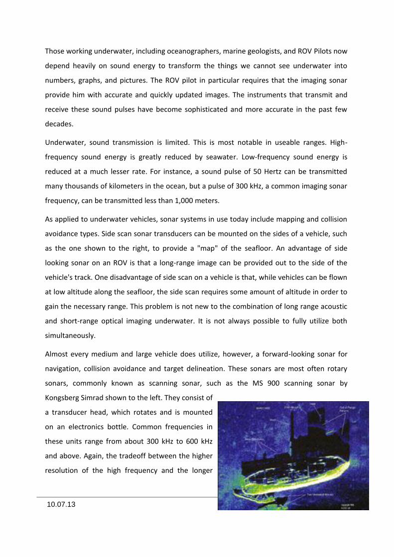
Almost every medium and large vehicle does utilize, however, a forward-looking sonar for
navigation, collision avoidance and target delineation. These sonars are most often rotary
sonars, commonly known as scanning sonar, such as the MS 900 scanning sonar by
Kongsberg Simrad shown to the left. They consist of
a transducer head, which rotates and is mounted
on an electronics bottle. Common frequencies in
these units range from about 300 kHz to 600 kHz
and above. Again, the tradeoff between the higher
resolution of the high frequency and the longer
10.07.13 Page 19 of 64
range of the low frequency comes into play. A vehicle may have more than one rotary scan
sonar mounted on it. Two frequencies on two sonar heads working simultaneously, for
example, will give a pilot a rapid informational update for targets and terrain on both high
resolution and long range.
The fact that towed side scan sonars "fly" high above their targets gives them their ability to
observe objects, often through the "shadows" cast by the sonar beam. This is shown
graphically in the figure of the ship image to the right. Today, color monitors and digital
processing enhance the sonar operator’s ability to identify targets.
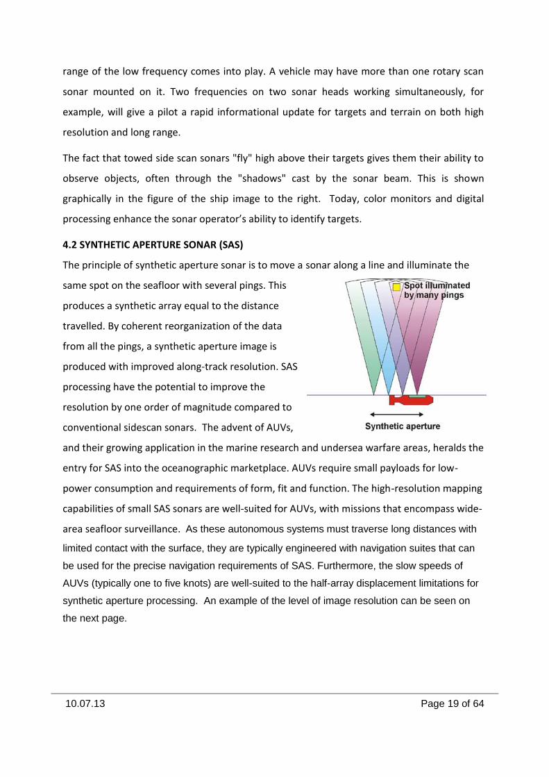
4.2 SYNTHETIC APERTURE SONAR (SAS)
The principle of synthetic aperture sonar is to move a sonar along a line and illuminate the
same spot on the seafloor with several pings. This
produces a synthetic array equal to the distance
travelled. By coherent reorganization of the data
from all the pings, a synthetic aperture image is
produced with improved along-track resolution. SAS
processing have the potential to improve the
resolution by one order of magnitude compared to
conventional sidescan sonars. The advent of AUVs,
and their growing application in the marine research and undersea warfare areas, heralds the
entry for SAS into the oceanographic marketplace. AUVs require small payloads for low-
power consumption and requirements of form, fit and function. The high-resolution mapping
capabilities of small SAS sonars are well-suited for AUVs, with missions that encompass wide-
area seafloor surveillance. As these autonomous systems must traverse long distances with
limited contact with the surface, they are typically engineered with navigation suites that can
be used for the precise navigation requirements of SAS. Furthermore, the slow speeds of
AUVs (typically one to five knots) are well-suited to the half-array displacement limitations for
synthetic aperture processing. An example of the level of image resolution can be seen on
the next page.

10.07.13 Page 20 of 64
10.07.13 Page 21 of 64
10.07.13 Page 22 of 64
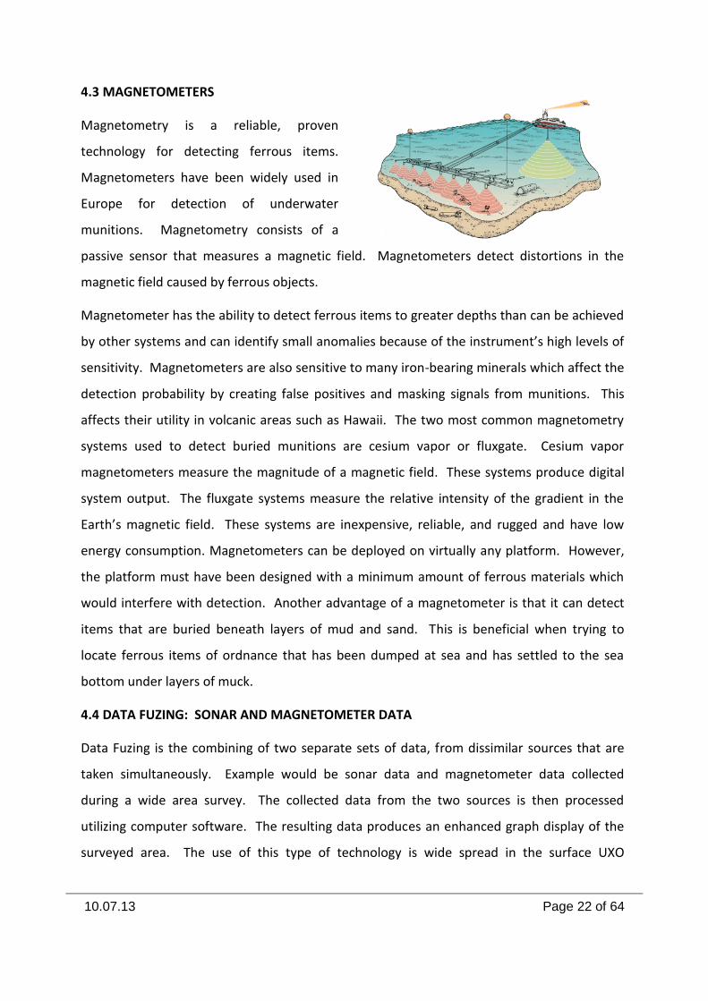
4.3 MAGNETOMETERS
Magnetometry is a reliable, proven
technology for detecting ferrous items.
Magnetometers have been widely used in
Europe for detection of underwater
munitions. Magnetometry consists of a
passive sensor that measures a magnetic field. Magnetometers detect distortions in the
magnetic field caused by ferrous objects.
Magnetometer has the ability to detect ferrous items to greater depths than can be achieved
by other systems and can identify small anomalies because of the instrument’s high levels of
sensitivity. Magnetometers are also sensitive to many iron-bearing minerals which affect the
detection probability by creating false positives and masking signals from munitions. This
affects their utility in volcanic areas such as Hawaii. The two most common magnetometry
systems used to detect buried munitions are cesium vapor or fluxgate. Cesium vapor
magnetometers measure the magnitude of a magnetic field. These systems produce digital
system output. The fluxgate systems measure the relative intensity of the gradient in the
Earth’s magnetic field. These systems are inexpensive, reliable, and rugged and have low
energy consumption. Magnetometers can be deployed on virtually any platform. However,
the platform must have been designed with a minimum amount of ferrous materials which
would interfere with detection. Another advantage of a magnetometer is that it can detect
items that are buried beneath layers of mud and sand. This is beneficial when trying to
locate ferrous items of ordnance that has been dumped at sea and has settled to the sea
bottom under layers of muck.
4.4 DATA FUZING: SONAR AND MAGNETOMETER DATA
Data Fuzing is the combining of two separate sets of data, from dissimilar sources that are
taken simultaneously. Example would be sonar data and magnetometer data collected
during a wide area survey. The collected data from the two sources is then processed
utilizing computer software. The resulting data produces an enhanced graph display of the
surveyed area. The use of this type of technology is wide spread in the surface UXO
10.07.13 Page 23 of 64
community. Terrance P. Long, President,
Wentworth Environmental Inc., and Thomas
deWilde, Geophysicist, aDede
www.ADEDE.com have combined a Iver2
Autonomous Underwater Vehicle (AUV)
equipped with Side-Scan Sonar (SSS)
technology and a marine Overhauser magnetometry. They have conducted a survey on Lake
Ontario, near Toronto, ON, Canada, and have proven that this method is far more reliable
than regular ship towed surveys utilizing the two separate technologies. Two pipelines and a
lost anchor could easily be recognized with the combined results of the magnetometer and
the SSS. On top of this, deviations from survey lines are far smaller and less likely than in
regular towed surveys, allowing surveys with a denser grid to be performed in rougher
waters, significantly increasing survey resolution.
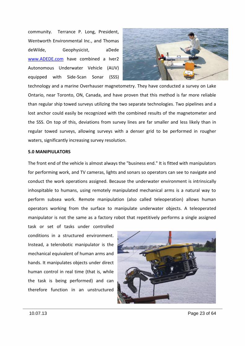
5.0 MANIPIULATORS
The front end of the vehicle is almost always the "business end." It is fitted with manipulators
for performing work, and TV cameras, lights and sonars so operators can see to navigate and
conduct the work operations assigned. Because the underwater environment is intrinsically
inhospitable to humans, using remotely manipulated mechanical arms is a natural way to
perform subsea work. Remote manipulation (also called teleoperation) allows human
operators working from the surface to manipulate underwater objects. A teleoperated
manipulator is not the same as a factory robot that repetitively performs a single assigned
task or set of tasks under controlled
conditions in a structured environment.
Instead, a telerobotic manipulator is the
mechanical equivalent of human arms and
hands. It manipulates objects under direct
human control in real time (that is, while
the task is being performed) and can
therefore function in an unstructured
10.07.13 Page 24 of 64
environment. The most basic remote manipulator systems contain only an operator-input
device and a jointed manipulator arm. More sophisticated systems also contain control
electronics. The tip of the manipulator arm is attached to a tool (such as a pair of jaws, a drill,
or a pair of snips) used to perform the required task. A wide variety of manipulator types
have evolved to cover a very broad range of subsea applications. These applications range
from simple tasks, such as grasping a lift line, to more complex ones, such as plugging and
unplugging electrical and hydraulic connectors. When selecting a manipulator, it is important
to choose the simplest possible type that can accomplish the task in a reasonable time. In the
offshore environment, complexity can generate problems with reliability, operation, and
maintenance.
The choice and integration of a manipulator system is complex, and the vehicle designer
should consider the following: number and types required, their location, required control
type (rate, spatially correspondent, force feedback), lift, maximum (and minimum) reach, and
camera locations. Remember, if you can’t see it, you can’t manipulate it. Manipulator arms
can provide multiple degrees of freedom of movement
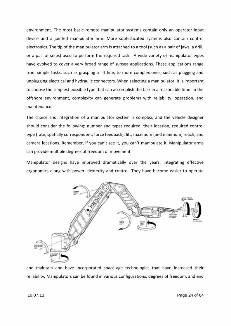
Manipulator designs have improved dramatically over the years, integrating effective
ergonomics along with power, dexterity and control. They have become easier to operate
and maintain and have incorporated space-age technologies that have increased their
reliability. Manipulators can be found in various configurations, degrees of freedom, and end
10.07.13 Page 25 of 64
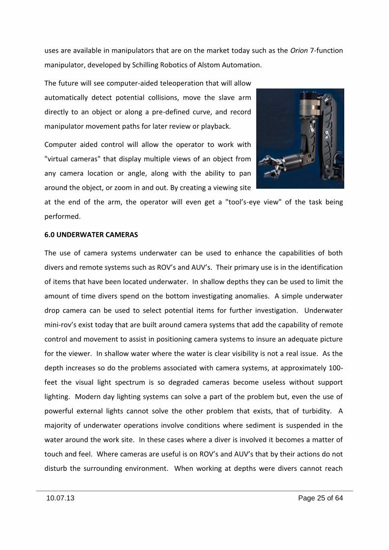
uses are available in manipulators that are on the market today such as the Orion 7-function
manipulator, developed by Schilling Robotics of Alstom Automation.
The future will see computer-aided teleoperation that will allow
automatically detect potential collisions, move the slave arm
directly to an object or along a pre-defined curve, and record
manipulator movement paths for later review or playback.
Computer aided control will allow the operator to work with
"virtual cameras" that display multiple views of an object from
any camera location or angle, along with the ability to pan
around the object, or zoom in and out. By creating a viewing site
at the end of the arm, the operator will even get a "tool’s-eye view" of the task being
performed.
6.0 UNDERWATER CAMERAS
The use of camera systems underwater can be used to enhance the capabilities of both
divers and remote systems such as ROV’s and AUV’s. Their primary use is in the identification
of items that have been located underwater. In shallow depths they can be used to limit the
amount of time divers spend on the bottom investigating anomalies. A simple underwater
drop camera can be used to select potential items for further investigation. Underwater
mini-rov’s exist today that are built around camera systems that add the capability of remote
control and movement to assist in positioning camera systems to insure an adequate picture
for the viewer. In shallow water where the water is clear visibility is not a real issue. As the
depth increases so do the problems associated with camera systems, at approximately 100-
feet the visual light spectrum is so degraded cameras become useless without support
lighting. Modern day lighting systems can solve a part of the problem but, even the use of
powerful external lights cannot solve the other problem that exists, that of turbidity. A
majority of underwater operations involve conditions where sediment is suspended in the
water around the work site. In these cases where a diver is involved it becomes a matter of
touch and feel. Where cameras are useful is on ROV’s and AUV’s that by their actions do not
disturb the surrounding environment. When working at depths were divers cannot reach
10.07.13 Page 26 of 64
safely, cameras are the only method of identifying those items found. Older monochromatic
cameras were difficult to use at deep depths. The older video cameras also had problems
focusing and providing a clear picture for the viewer. With the advent of digital cameras and
computer assisted software some of these problems are minimized. Newer systems being
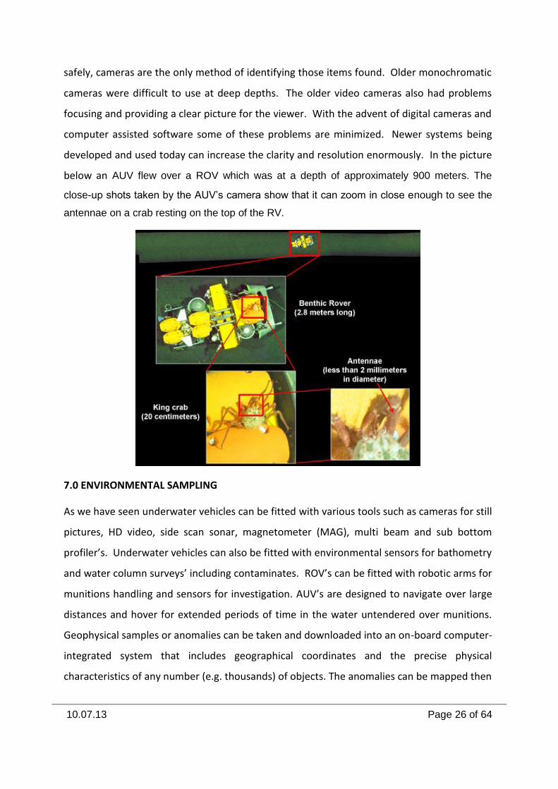
developed and used today can increase the clarity and resolution enormously. In the picture
below an AUV flew over a ROV which was at a depth of approximately 900 meters. The
close-up shots taken by the AUV’s camera show that it can zoom in close enough to see the
antennae on a crab resting on the top of the RV.
7.0 ENVIRONMENTAL SAMPLING
As we have seen underwater vehicles can be fitted with various tools such as cameras for still
pictures, HD video, side scan sonar, magnetometer (MAG), multi beam and sub bottom
profiler’s. Underwater vehicles can also be fitted with environmental sensors for bathometry
and water column surveys’ including contaminates. ROV’s can be fitted with robotic arms for
munitions handling and sensors for investigation. AUV’s are designed to navigate over large
distances and hover for extended periods of time in the water untendered over munitions.
Geophysical samples or anomalies can be taken and downloaded into an on-board computer-
integrated system that includes geographical coordinates and the precise physical
characteristics of any number (e.g. thousands) of objects. The anomalies can be mapped then
10.07.13 Page 27 of 64
reacquired and addressed at a later date for investigation or remedial action by a diver or
underwater vehicle.
A part of the environmental sampling process is a risk analysis of the condition of the
munitions that has been found. This analysis will dictate the remediation and disposal
procedures that will be used. The first and foremost is the determination if the items contain
armed or partially armed fuze(s). The secondary and more common issue concerns the
structural integrity of each item to be recovered.
Items containing armed or partially armed fuze(s) will require (if possible) to be rendered
safe. If that is not possible then an alternative disposal method(s) may have to be
considered.
Alterative methods for reducing the exposure to munitions that are located on the sea floor
include both active and passive steps.
Active steps involve reducing or eliminating the potential exposure to the munitions. This
could be accomplished by various engineering options that range from laying dredge material
such as sand on top of the munitions to the established of an island on top of an entire area.
The Belgium Government conducted a study regarding the discovery of WW-I chemical
munitions that were disposed of off their coast, north of the town of Zeebrugge. Because of
the shallow nature of the area and the close proximity of the shoreline the Belgium
government was concerned and funded a report containing an evaluation of this site.
Four potential engineering options were discussed in the report.
The first option would be the construction of a cover on top of the munitions, consisting of
sediments, such as sand and gravel. The study suggested that a minimum of 5-feet of
sediment would be needed to provide a safe cover. To utilize this method successfully the
area must not have high erosion rates due to tidal currents or waves. The use of this process
would also require constant monitoring to insure items do not become exposed.
The second option that was investigated was the use of stone/concrete rip-rap to cover the
5-foot layer of sediment. The design of this option would entail multiple layers of rip-rap
starting with smaller diameter material and building to larger material. The establishment of
10.07.13 Page 28 of 64
a cover on top of a sediment cover will prevent erosion from occurring and would provide
protection from ship anchors. Monitoring would still be required but, not as frequently as
with just a sediment cover.
The third option involves the construction of a Breakwater on the seaward side where the
munitions are located at. The idea behind this was that sediment would build behind the
breakwaters to cover the munitions. Utilizing this process a constant layer of sediment is
deposited on the munitions.
The last option involves the construction of an island over the entire area that munitions are
located. This technology approach is being used worldwide to reclaim land and involves a
massive engineering effort.
Passive measures, while are less costly requires that people follow established guidelines.
The simplest of passive measures would be the establishment of restricted areas where
recreational would be prohibited and strict controls placed on commercial usage where
suspected chemical munitions are located at. In order for this process to be successful, it will
require that the boundaries for all sea disposal locations be identified and mapped.
Items that have structural integrity problems from corrosion or from internal design is a very
important point to consider.
8.0 REMEDIATION/DISPOSAL
Recovery of munitions is a high risk and high cost operation. During removal, mechanical
actions could damage the munitions resulting in a leak or detonation. In the case of Chemical
Agent (CA) filled munitions there is the possibility for the release of large quantities of CA.
However, recovery is the only action that would provide a permanent reduction in risk.
Treatment of the CA as it is released to near bottom waters has some severe technological
challenges. These include temperatures which slow the rate of chemical reactions and
difficulty in maintaining proper reagent concentrations to assure destruction of the CA. This
alternative is complicated when different types of CA are present and differing reagent are
required.
10.07.13 Page 29 of 64
Containment could be accomplished through placement of an inert covering material to
prevent or slow the corrosion of the CWM and release of the CA. It is also possible for the
materials used for containment to include a reagent capable of degrading the CA.
Recovery of individual items has traditionally been conducted by divers. Low visibility,
sedimentation, and biological and mineral coatings on munitions makes identification and
determining the items’ is fuzing and arming status difficult if not impossible. This uncertainty
in conjunction with the increased hazard associated with a shockwave from a detonation
makes assuring worker safety a priority. In those cases where CA maybe present or in the
case where risks to divers are too great, the use of ROV technology that is currently available
must be used. Large scale recovery of underwater munitions has only seldom occurred and
has never been conducted for CWM. The only large scale munitions recovery effort known
was conducted off the coast of Germany following World War II through the late 1950s. The
metals in the ammunition were useful in starting post-war industrial production. Thus,
disassembly became a viable alternative to dumping and recovery of previously disposed
munitions was started. Immediately following the war, torpedo nets were used for recovery.
A variety of devices including electromagnets, dredges and drags were also used. Using the
magnets, munitions buried in up to five feet of sand were recovered. The grabs were also
effective in recovering buried munitions. The recovery operation was conducted commercial
salvage of the metals. This was initially productive but by 1957 only two ships remained in
operation. A plant recovering the metals experienced a large explosion in 1953 and ceased
accepting certain types of ammunition which was re-disposed. Between July 1952 and
December 1954 the plant processed approximately 50,000 tons of ammunition.
Due to environmental conditions which are likely to have affected the items in different ways
and the variety of potential fills disposed in the same areas, each item so difficult to handle
to the point that each must be treated as unique. Specialists must evaluate each item and
determine the most appropriate destruction technique.
Today’s technology is available for underwater munitions response applications including
specialized underwater heavy equipment for shallow and deep water operations. One
example is a large remotely operated excavator (ROE) from Norway developed for Oil and
10.07.13 Page 30 of 64
Gas that can operate up to a depth of 2,500 meters in the oceans with similar capabilities of
underwater vehicles. The underwater excavators have the ability to: excavate munitions and
other debris from the sea floor; vacuum discarded military munitions (unfuzed) up to 46 cm
in diameter; vacuum munitions constituents from the sea floor to a top-side facility or
surface vessel for treatment and recycle; relocate
munitions from the sea floor to the surface or for
disposal; and or bury munitions under the sea floor
to an approximate depth of 10-15 meters.
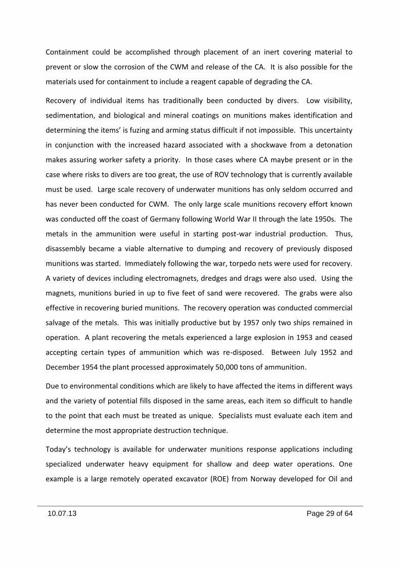
technologies involve the use of specialized
equipment that is designed to remotely move
hazardous items of ordnance. Underwater
Ordnance Recovery, Inc. has developed a remote
operated mechanical lifting device that can operate
at both shallow and extreme depths. This type of
technology coupled with the use of what are called
“Lift Bags” can be used in shallow to medium depths
to remove munitions from the seabed. The use of
lift bag technology has been around for a long time and has provided to be successful by
military EOD operations and by commercial underwater salvage divers. By utilizing a remote
handling device to pick-up and move an item of ordnance, it could be then placed remotely in
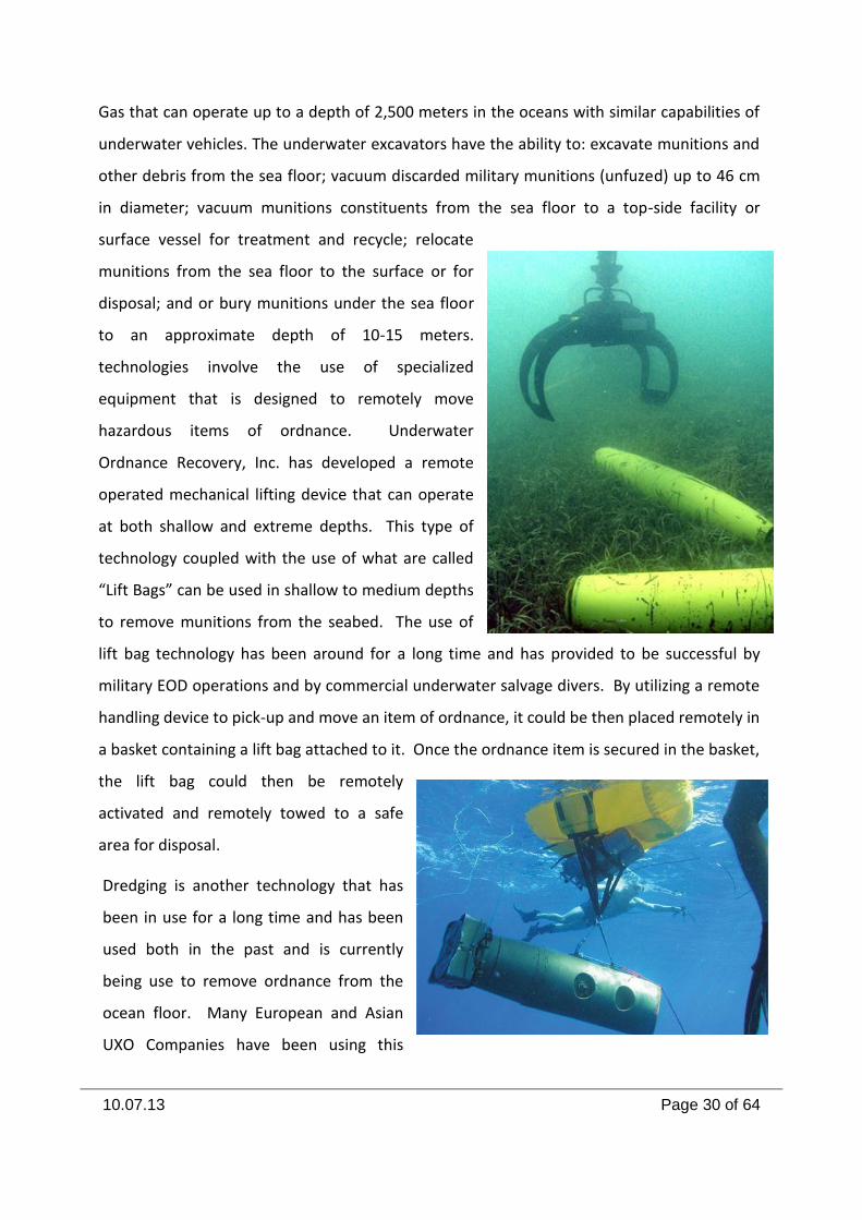
a basket containing a lift bag attached to it. Once the ordnance item is secured in the basket,
the lift bag could then be remotely
activated and remotely towed to a safe
area for disposal.
Dredging is another technology that has
been in use for a long time and has been
used both in the past and is currently
being use to remove ordnance from the
ocean floor. Many European and Asian
UXO Companies have been using this
10.07.13 Page 31 of 64
technology to remove munitions from underwater locations worldwide. The U.S.
Department of Defense research agency, Environmental Security Technology Certification
Program (ESTCP) in a project report, MM-0321, “Dredging Equipment Modifications for
Detection and Removal of Ordnance” dated December 2006 identified 15 separate occasions
where dredging was used to recover munitions from underwater locations. An example of
the information contained in this report is the Kokkola Channel Project.
The port of Kokkola is located on Finland’s Gulf of Bothnia coast. In 1995, the Finnish
Maritime Administration initiated port development projects that included improved access
to the channel and land reclamation. During 1997–2001, the depth of the Kokkola channel
was increased from 11 m to 13 m , with dredging depths to 15.6 m.
During this operation, the trailer dredge Nautilus had to stop work. While dredging in the
inner channel, military munitions were found in the trailer’s drag head. Subsequent
investigation indicated that the port of Kokkola was a previous transit route for vessels
carrying decommissioned ordnance from just after WWII to 1974. A depression located 50
km from the port was apparently designated as a final military munitions disposal site during
the period in question. Munitions were also disposed of in the adjacent shipping lane. In
addition, this area had been bombed during WWII, causing this area to be subsequently
assessed as extremely dangerous because of the potential for finding large unexploded aerial
bombs. Dredging operations in the area were delayed while the Finnish Defense Forces and
the “Terramare OY” dredging company developed new safety procedures for dredging and
for handling the material containing the dredged military munitions. At the same time, it was
necessary to determine if unexploded 500-kg aerial bombs existed in the area. Project
planning and modifications were scheduled during the autumn of 1997 into the spring of
1998. Changes to the dredging procedure and dredging equipment were subsequently
employed. Based on the inability to determine whether a magnetic signature would
represent an explosive or non-explosive object, the plan had to consider blast danger relating
to the potential for a large aerial bomb to explode during the dredging process. A remote-
controlled dredging approach with a mechanical dredge was developed based on the
conclusion that the dredge and personnel working on the dredger could not be protected
from the explosion of a 500-kg aerial bomb. An operating raft was developed to remotely
10.07.13 Page 32 of 64
control the dredge functions from a safe offset distance of up to 500 m. The dredge
operator’s commands were transferred via radio control from the raft to the dredge. The
operator would effectively perform the same actions as if he were on the dredge. Cameras
and monitoring equipment were mounted on the dredge to inform the operator (located on
the raft) of the dredging parameters and circumstances. Arrays of magnetometers were
towed through the area to locate and identify ferrous magnetic signatures. Remote-
controlled dredging was carried out at each ferromagnetic signature location of 37 mm or
greater; otherwise, normal dredging operations predominated. Dredging was remotely
controlled within a 10-m radius of the detection points. The total dredging area was
approximately 3.5-km long and 300-m wide. The volume of material (clay and silt) containing
military munitions was estimated at 1.2 million m3.
Military munitions found included cartridges, artillery, and grenade launcher rounds, fuzes
for artillery projectiles (projectiles ranging from 37 mm to 155 mm in diameter), and aerial
bombs of 100 to 500 kg. The ammunition ranged in size from small arms to 0.5 m in length
and was normally cylindrical. To dredge in the ammunition-littered region, the dredge
Kahmari, a remotely controlled grab dredge with a 5 m3 clamshell, was used. Additionally,
the areas surrounding the ammunition-contaminated region were cleared by using a 7 m3
bucket backhoe, the Koura, and a 15 m3 bucket grab dredge, the Meri-Pekka, both of which
were manned. For the manned dredging operations, personnel were protected with
bulletproof glass and steel safety partitions. The material obtained by remote-controlled
dredging was transported to a separate disposal area by a split hull barge with a 300-m3
capacity. Material removal/disposal from the barge
was remotely controlled from a tug at a standoff distance of 300 m . The containment basin
for final disposal of the material containing unexploded ordnance was 300 m by 500 m. A
gravel berm surrounding the basin was constructed with 600,000 m3 of blasted rock to a
depth of 10 m. The basin was backfilled with clean earth material after the dredged material
was placed in the basin. The material from the surrounding area was transported by manned
600 m3 split-hopper barges to a reclamation site.
10.07.13 Page 33 of 64
The ESTCP report along with its sister agency the Strategic Environmental Research and
Development Program (SERDP) has shown that recovery technologies do exist and that a
wide range of companies are in a position to use those technologies.
After the safe and environmentally appropriate recovery of hazardous munitions has been
accomplish, the next challenges is the safe disposal in a manner that does not harm the
environment.
Where large quantities of munitions are located underwater, open air detonation and
underwater disposal are problematic. In some cases, this may cause more harm to the
environment than if they were left in place to slowly decay.
Although there are many possible munitions disposal approaches, two that are applicable to
both chemical and conventional munitions are the controlled detonation chamber (CDC)
systems and the static detonation chamber (SDC) systems. Technology developers have
provided several solutions for safe and environmental friendly disposal. Four examples of
these types of technology have been reviewed by the U.S. Department of Defense and a
report issued by the U.S. Army Board Science and Technology Board describes how each
system works:
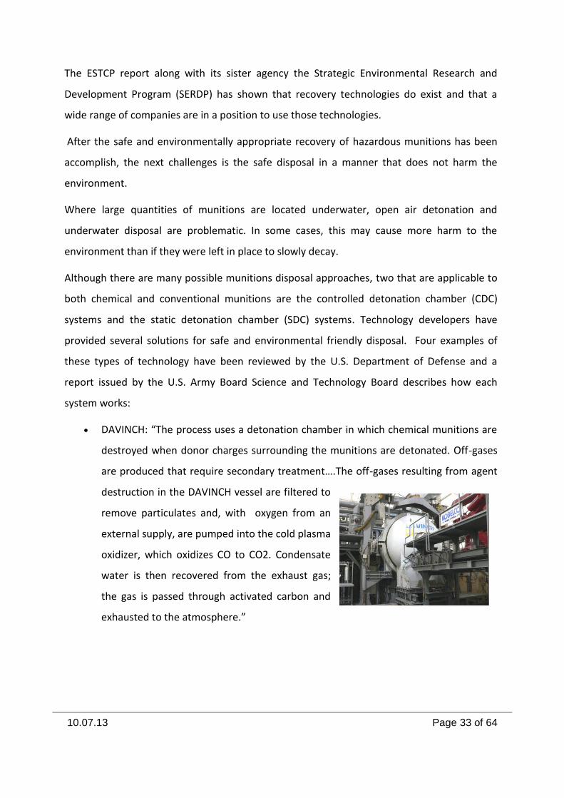
DAVINCH: “The process uses a detonation chamber in which chemical munitions are
destroyed when donor charges surrounding the munitions are detonated. Off-gases
are produced that require secondary treatment….The off-gases resulting from agent
destruction in the DAVINCH vessel are filtered to
remove particulates and, with oxygen from an
external supply, are pumped into the cold plasma
oxidizer, which oxidizes CO to CO2. Condensate
water is then recovered from the exhaust gas;
the gas is passed through activated carbon and
exhausted to the atmosphere.”
10.07.13 Page 34 of 64
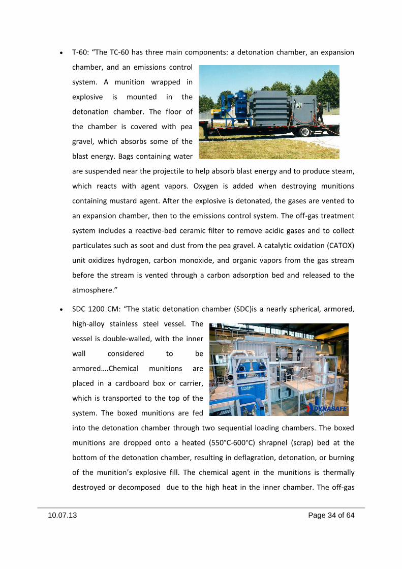
T-60: “The TC-60 has three main components: a detonation chamber, an expansion
chamber, and an emissions control
system. A munition wrapped in
explosive is mounted in the
detonation chamber. The floor of
the chamber is covered with pea
gravel, which absorbs some of the
blast energy. Bags containing water
are suspended near the projectile to help absorb blast energy and to produce steam,
which reacts with agent vapors. Oxygen is added when destroying munitions
containing mustard agent. After the explosive is detonated, the gases are vented to
an expansion chamber, then to the emissions control system. The off-gas treatment
system includes a reactive-bed ceramic filter to remove acidic gases and to collect
particulates such as soot and dust from the pea gravel. A catalytic oxidation (CATOX)
unit oxidizes hydrogen, carbon monoxide, and organic vapors from the gas stream
before the stream is vented through a carbon adsorption bed and released to the
atmosphere.”
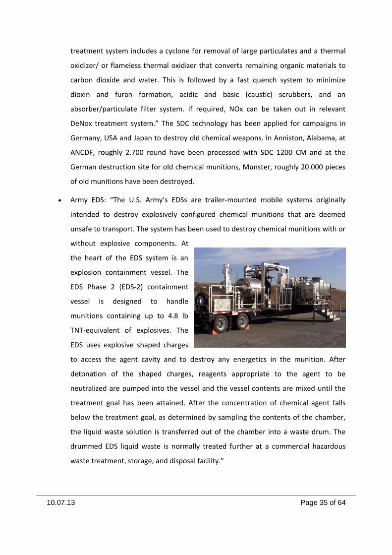
SDC 1200 CM: “The static detonation chamber (SDC)is a nearly spherical, armored,
high-alloy stainless steel vessel. The
vessel is double-walled, with the inner
wall considered to be
armored….Chemical munitions are
placed in a cardboard box or carrier,
which is transported to the top of the
system. The boxed munitions are fed
into the detonation chamber through two sequential loading chambers. The boxed
munitions are dropped onto a heated (550°C-600°C) shrapnel (scrap) bed at the
bottom of the detonation chamber, resulting in deflagration, detonation, or burning
of the munition’s explosive fill. The chemical agent in the munitions is thermally
destroyed or decomposed due to the high heat in the inner chamber. The off-gas
10.07.13 Page 35 of 64
treatment system includes a cyclone for removal of large particulates and a thermal
oxidizer/ or flameless thermal oxidizer that converts remaining organic materials to
carbon dioxide and water. This is followed by a fast quench system to minimize
dioxin and furan formation, acidic and basic (caustic) scrubbers, and an
absorber/particulate filter system. If required, NOx can be taken out in relevant
DeNox treatment system.” The SDC technology has been applied for campaigns in
Germany, USA and Japan to destroy old chemical weapons. In Anniston, Alabama, at
ANCDF, roughly 2.700 round have been processed with SDC 1200 CM and at the
German destruction site for old chemical munitions, Munster, roughly 20.000 pieces
of old munitions have been destroyed.
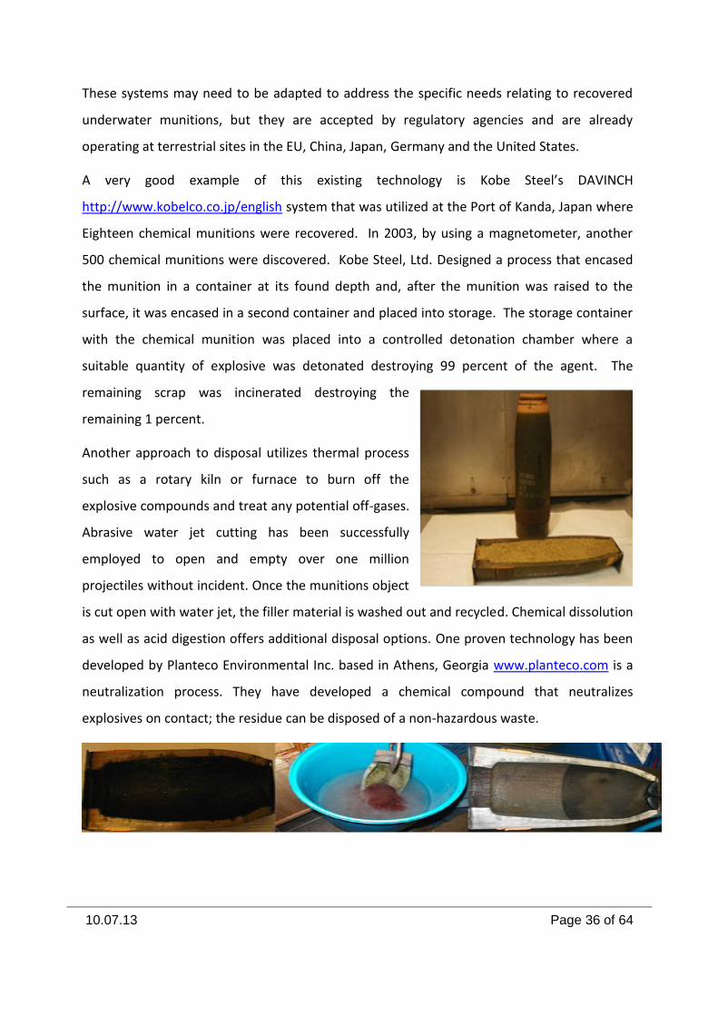
Army EDS: “The U.S. Army’s EDSs are trailer-mounted mobile systems originally
intended to destroy explosively configured chemical munitions that are deemed
unsafe to transport. The system has been used to destroy chemical munitions with or
without explosive components. At
the heart of the EDS system is an
explosion containment vessel. The
EDS Phase 2 (EDS-2) containment
vessel is designed to handle
munitions containing up to 4.8 lb
TNT-equivalent of explosives. The
EDS uses explosive shaped charges
to access the agent cavity and to destroy any energetics in the munition. After
detonation of the shaped charges, reagents appropriate to the agent to be
neutralized are pumped into the vessel and the vessel contents are mixed until the
treatment goal has been attained. After the concentration of chemical agent falls
below the treatment goal, as determined by sampling the contents of the chamber,
the liquid waste solution is transferred out of the chamber into a waste drum. The
drummed EDS liquid waste is normally treated further at a commercial hazardous
waste treatment, storage, and disposal facility.”
10.07.13 Page 36 of 64
These systems may need to be adapted to address the specific needs relating to recovered
underwater munitions, but they are accepted by regulatory agencies and are already
operating at terrestrial sites in the EU, China, Japan, Germany and the United States.
A very good example of this existing technology is Kobe Steel’s DAVINCH
http://www.kobelco.co.jp/english system that was utilized at the Port of Kanda, Japan where
Eighteen chemical munitions were recovered. In 2003, by using a magnetometer, another
500 chemical munitions were discovered. Kobe Steel, Ltd. Designed a process that encased
the munition in a container at its found depth and, after the munition was raised to the
surface, it was encased in a second container and placed into storage. The storage container
with the chemical munition was placed into a controlled detonation chamber where a
suitable quantity of explosive was detonated destroying 99 percent of the agent. The
remaining scrap was incinerated destroying the
remaining 1 percent.
Another approach to disposal utilizes thermal process
such as a rotary kiln or furnace to burn off the
explosive compounds and treat any potential off-gases.
Abrasive water jet cutting has been successfully
employed to open and empty over one million
projectiles without incident. Once the munitions object
is cut open with water jet, the filler material is washed out and recycled. Chemical dissolution
as well as acid digestion offers additional disposal options. One proven technology has been
developed by Planteco Environmental Inc. based in Athens, Georgia www.planteco.com is a
neutralization process. They have developed a chemical compound that neutralizes
explosives on contact; the residue can be disposed of a non-hazardous waste.
10.07.13 Page 37 of 64
Based on this new technology and the use of the water jet cutting process, conventional
explosive munitions can now be quickly disposed of in an environmentally friendly manner.
Destructive and non-destructive methods to dispose of underwater munitions have greatly
improved over the past decade. One aspect that has been a point of concern that is both
associate with disposal of underwater munitions has been the noise levels and the
environmental effects that are created when detonations occur underwater. The harmful
effect is also associated with the majority of other technologies involved in the detection and
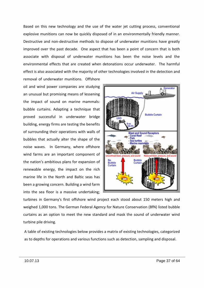
removal of underwater munitions. Offshore
oil and wind power companies are studying
an unusual but promising means of lessening
the impact of sound on marine mammals:
bubble curtains. Adapting a technique that
proved successful in underwater bridge
building, energy firms are testing the benefits
of surrounding their operations with walls of
bubbles that actually alter the shape of the
noise waves. In Germany, where offshore
wind farms are an important component of
the nation's ambitious plans for expansion of
renewable energy, the impact on the rich
marine life in the North and Baltic seas has
been a growing concern. Building a wind farm
into the sea floor is a massive undertaking;
turbines in Germany's first offshore wind project each stood about 150 meters high and
weighed 1,000 tons. The German Federal Agency for Nature Conservation (BfN) listed bubble
curtains as an option to meet the new standard and mask the sound of underwater wind
turbine pile driving.
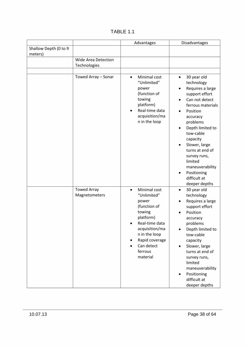
A table of existing technologies below provides a matrix of existing technologies, categorized
as to depths for operations and various functions such as detection, sampling and disposal.
10.07.13 Page 38 of 64
TABLE 1.1
Advantages Disadvantages
Shallow Depth (0 to 9 meters)
Wide Area Detection Technologies
Towed Array – Sonar Minimal cost “Unlimited” power (function of towing platform)
Real-time data acquisition/man in the loop
30 year old technology
Requires a large support effort
Can not detect ferrous materials
Position accuracy problems
Depth limited to tow-cable capacity
Slower, large turns at end of survey runs, limited maneuverability
Positioning difficult at deeper depths
Towed Array Magnetometers
Minimal cost “Unlimited” power (function of towing platform)
Real-time data acquisition/man in the loop
Rapid coverage
Can detect ferrous material
30 year old technology
Requires a large support effort
Position accuracy problems
Depth limited to tow-cable capacity
Slower, large turns at end of survey runs, limited maneuverability
Positioning difficult at deeper depths
10.07.13 Page 39 of 64
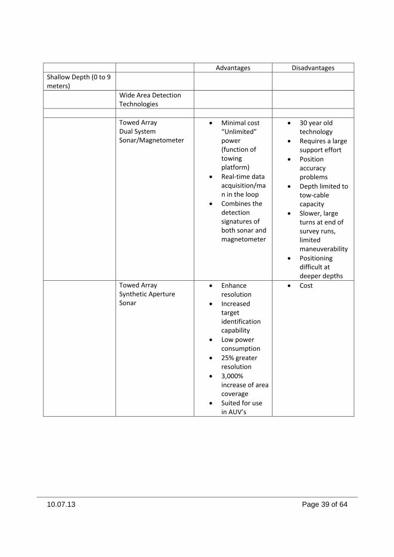
Advantages Disadvantages
Shallow Depth (0 to 9 meters)
Wide Area Detection Technologies
Towed Array Dual System Sonar/Magnetometer
Minimal cost “Unlimited” power (function of towing platform)
Real-time data acquisition/man in the loop
Combines the detection signatures of both sonar and magnetometer
30 year old technology
Requires a large support effort
Position accuracy problems
Depth limited to tow-cable capacity
Slower, large turns at end of survey runs, limited maneuverability
Positioning difficult at deeper depths
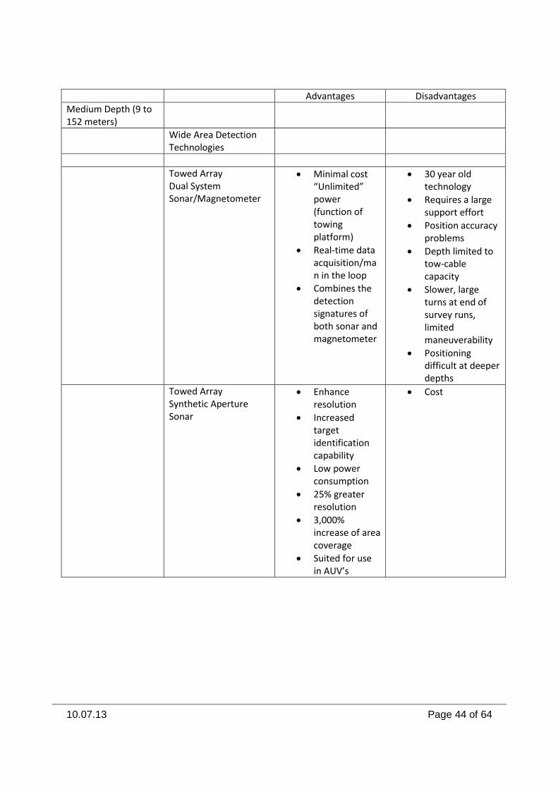
Towed Array Synthetic Aperture Sonar
Enhance resolution
Increased target identification capability
Low power consumption
25% greater resolution
3,000% increase of area coverage
Suited for use in AUV’s
Cost
10.07.13 Page 40 of 64
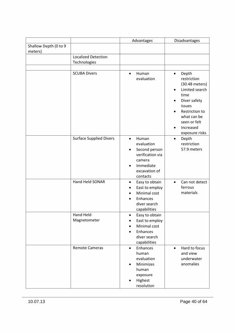
Advantages Disadvantages
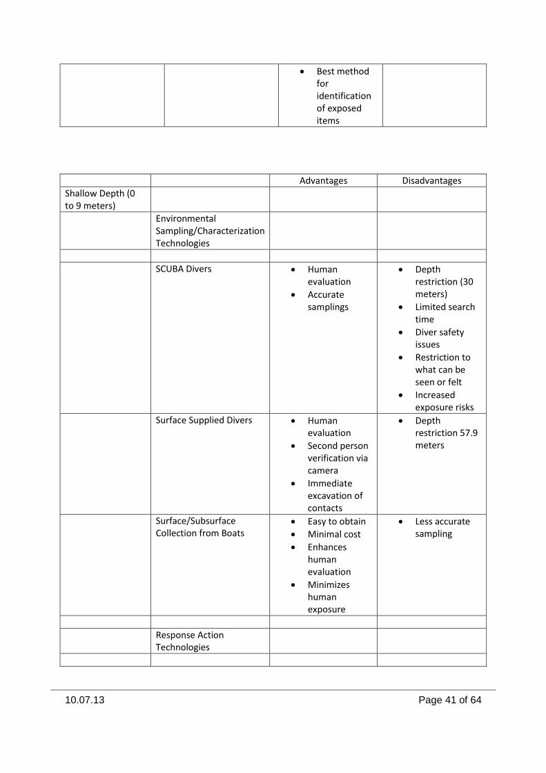
Shallow Depth (0 to 9 meters)
Localized Detection Technologies
SCUBA Divers Human evaluation
Depth restriction (30.48 meters)
Limited search time
Diver safety issues
Restriction to what can be seen or felt
Increased exposure risks
Surface Supplied Divers Human evaluation
Second person verification via camera
Immediate excavation of contacts
Depth restriction 57.9 meters
Hand Held SONAR Easy to obtain
East to employ
Minimal cost
Enhances diver search capabilities
Can not detect ferrous materials
Hand Held Magnetometer
Easy to obtain
East to employ
Minimal cost
Enhances diver search capabilities
Remote Cameras Enhances human evaluation
Minimizes human exposure
Highest resolution
Hard to focus and view underwater anomalies
10.07.13 Page 41 of 64
Best method for identification of exposed items
Advantages Disadvantages
Shallow Depth (0 to 9 meters)
Environmental Sampling/Characterization Technologies
SCUBA Divers Human evaluation
Accurate samplings
Depth restriction (30 meters)
Limited search time
Diver safety issues
Restriction to what can be seen or felt
Increased exposure risks
Surface Supplied Divers Human evaluation
Second person verification via camera
Immediate excavation of contacts
Depth restriction 57.9 meters
Surface/Subsurface Collection from Boats
Easy to obtain
Minimal cost
Enhances human evaluation
Minimizes human exposure
Less accurate sampling
Response Action Technologies
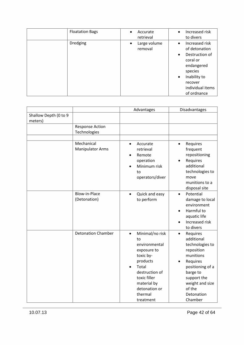
10.07.13 Page 42 of 64
Floatation Bags Accurate retrieval
Increased risk to divers
Dredging Large volume removal
Increased risk of detonation
Destruction of coral or endangered species
Inability to recover individual items of ordnance
Advantages Disadvantages
Shallow Depth (0 to 9 meters)
Response Action Technologies
Mechanical Manipulator Arms
Accurate retrieval
Remote operation
Minimum risk to operators/diver
Requires frequent repositioning
Requires additional technologies to move munitions to a disposal site
Blow-in-Place (Detonation)
Quick and easy to perform
Potential damage to local environment
Harmful to aquatic life
Increased risk to divers
Detonation Chamber Minimal/no risk to environmental exposure to toxic by-products
Total destruction of toxic filler material by detonation or thermal treatment
Requires additional technologies to reposition munitions
Requires positioning of a barge to support the weight and size of the Detonation Chamber
10.07.13 Page 43 of 64
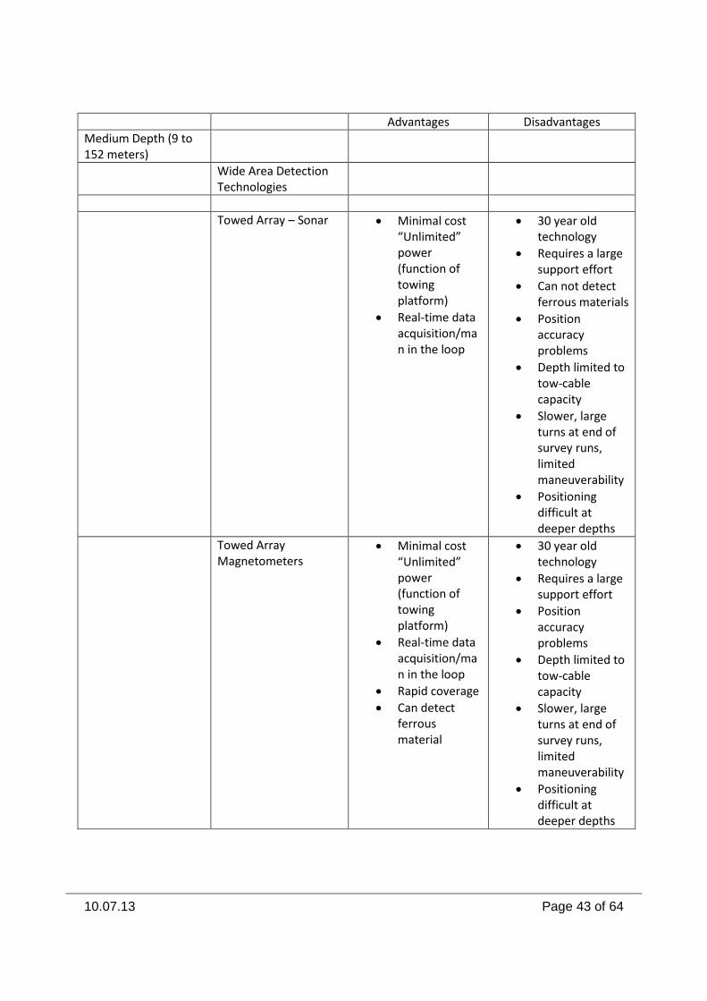
Advantages Disadvantages
Medium Depth (9 to 152 meters)
Wide Area Detection Technologies
Towed Array – Sonar Minimal cost “Unlimited” power (function of towing platform)
Real-time data acquisition/man in the loop
30 year old technology
Requires a large support effort
Can not detect ferrous materials
Position accuracy problems
Depth limited to tow-cable capacity
Slower, large turns at end of survey runs, limited maneuverability
Positioning difficult at deeper depths
Towed Array Magnetometers
Minimal cost “Unlimited” power (function of towing platform)
Real-time data acquisition/man in the loop
Rapid coverage
Can detect ferrous material
30 year old technology
Requires a large support effort
Position accuracy problems
Depth limited to tow-cable capacity
Slower, large turns at end of survey runs, limited maneuverability
Positioning difficult at deeper depths
10.07.13 Page 44 of 64
Advantages Disadvantages
Medium Depth (9 to 152 meters)
Wide Area Detection Technologies
Towed Array Dual System Sonar/Magnetometer
Minimal cost “Unlimited” power (function of towing platform)
Real-time data acquisition/man in the loop
Combines the detection signatures of both sonar and magnetometer
30 year old technology
Requires a large support effort
Position accuracy problems
Depth limited to tow-cable capacity
Slower, large turns at end of survey runs, limited maneuverability
Positioning difficult at deeper depths
Towed Array Synthetic Aperture Sonar
Enhance resolution
Increased target identification capability
Low power consumption
25% greater resolution
3,000% increase of area coverage
Suited for use in AUV’s
Cost
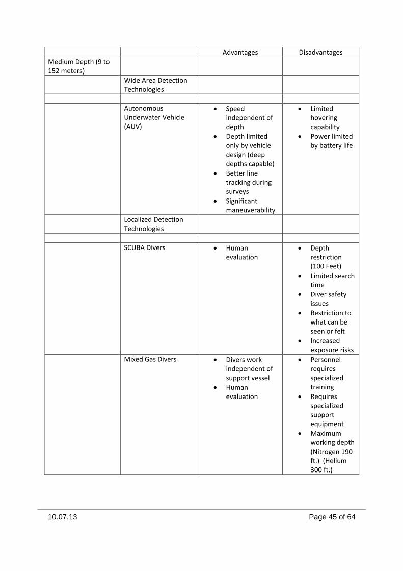
10.07.13 Page 45 of 64
Advantages Disadvantages
Medium Depth (9 to 152 meters)
Wide Area Detection Technologies
Autonomous Underwater Vehicle (AUV)
Speed independent of depth
Depth limited only by vehicle design (deep depths capable)
Better line tracking during surveys
Significant maneuverability
Limited hovering capability
Power limited by battery life
Localized Detection Technologies
SCUBA Divers Human evaluation
Depth restriction (100 Feet)
Limited search time
Diver safety issues
Restriction to what can be seen or felt
Increased exposure risks
Mixed Gas Divers Divers work independent of support vessel
Human evaluation
Personnel requires specialized training
Requires specialized support equipment
Maximum working depth (Nitrogen 190 ft.) (Helium 300 ft.)
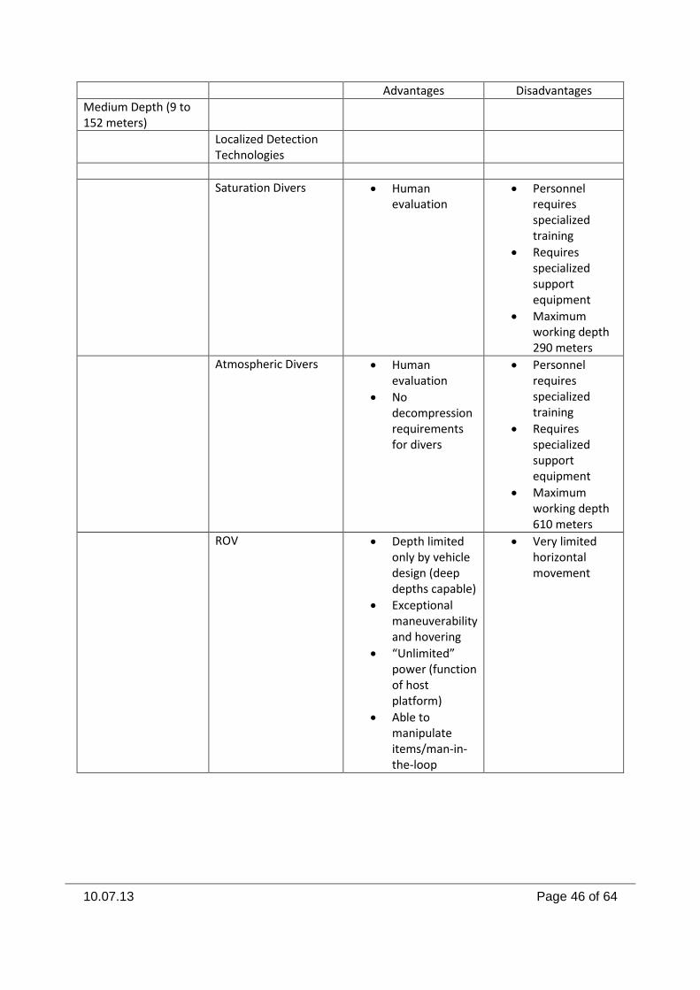
10.07.13 Page 46 of 64
Advantages Disadvantages
Medium Depth (9 to 152 meters)
Localized Detection Technologies
Saturation Divers Human evaluation
Personnel requires specialized training
Requires specialized support equipment
Maximum working depth 290 meters
Atmospheric Divers Human evaluation
No decompression requirements for divers
Personnel requires specialized training
Requires specialized support equipment
Maximum working depth 610 meters
ROV Depth limited only by vehicle design (deep depths capable)
Exceptional maneuverability and hovering
“Unlimited” power (function of host platform)
Able to manipulate items/man-in-the-loop
Very limited horizontal movement
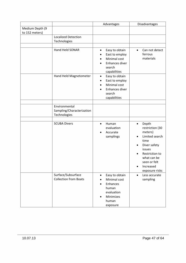
10.07.13 Page 47 of 64
Advantages Disadvantages
Medium Depth (9 to 152 meters)
Localized Detection Technologies
Hand Held SONAR Easy to obtain
East to employ
Minimal cost
Enhances diver search capabilities
Can not detect ferrous materials
Hand Held Magnetometer Easy to obtain
East to employ
Minimal cost
Enhances diver search capabilities
Environmental Sampling/Characterization Technologies
SCUBA Divers Human evaluation
Accurate samplings
Depth restriction (30 meters)
Limited search time
Diver safety issues
Restriction to what can be seen or felt
Increased exposure risks
Surface/Subsurface Collection from Boats
Easy to obtain
Minimal cost
Enhances human evaluation
Minimizes human exposure
Less accurate sampling
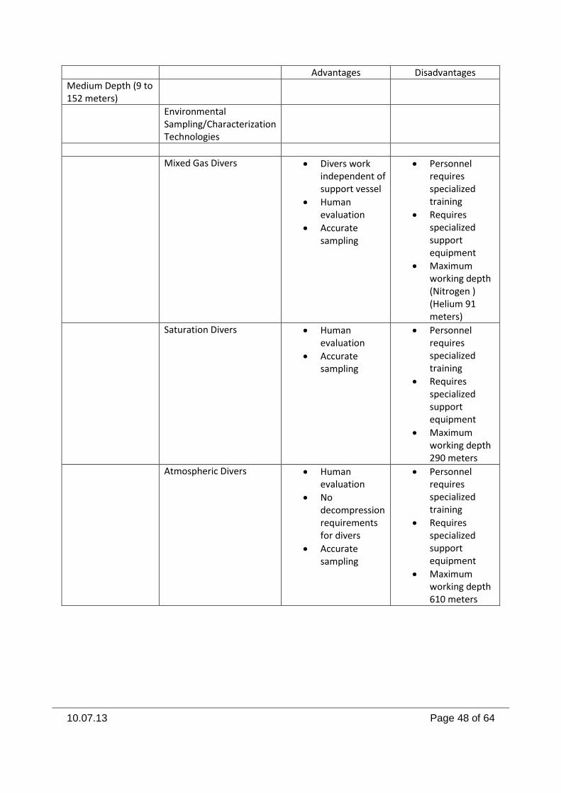
10.07.13 Page 48 of 64
Advantages Disadvantages
Medium Depth (9 to 152 meters)
Environmental Sampling/Characterization Technologies
Mixed Gas Divers Divers work independent of support vessel
Human evaluation
Accurate sampling
Personnel requires specialized training
Requires specialized support equipment
Maximum working depth (Nitrogen ) (Helium 91 meters)
Saturation Divers Human evaluation
Accurate sampling
Personnel requires specialized training
Requires specialized support equipment
Maximum working depth 290 meters
Atmospheric Divers Human evaluation
No decompression requirements for divers
Accurate sampling
Personnel requires specialized training
Requires specialized support equipment
Maximum working depth 610 meters
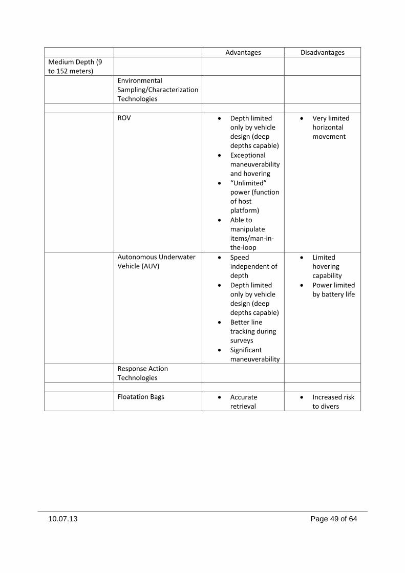
10.07.13 Page 49 of 64
Advantages Disadvantages
Medium Depth (9 to 152 meters)
Environmental Sampling/Characterization Technologies
ROV Depth limited only by vehicle design (deep depths capable)
Exceptional maneuverability and hovering
“Unlimited” power (function of host platform)
Able to manipulate items/man-in-the-loop
Very limited horizontal movement
Autonomous Underwater Vehicle (AUV)
Speed independent of depth
Depth limited only by vehicle design (deep depths capable)
Better line tracking during surveys
Significant maneuverability
Limited hovering capability
Power limited by battery life
Response Action Technologies
Floatation Bags Accurate retrieval
Increased risk to divers
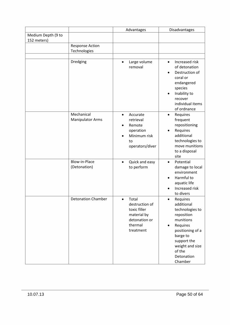
10.07.13 Page 50 of 64
Advantages Disadvantages
Medium Depth (9 to 152 meters)
Response Action Technologies
Dredging Large volume removal
Increased risk of detonation
Destruction of coral or endangered species
Inability to recover individual items of ordnance
Mechanical Manipulator Arms
Accurate retrieval
Remote operation
Minimum risk to operators/diver
Requires frequent repositioning
Requires additional technologies to move munitions to a disposal site
Blow-in-Place (Detonation)
Quick and easy to perform
Potential damage to local environment
Harmful to aquatic life
Increased risk to divers
Detonation Chamber Total destruction of toxic filler material by detonation or thermal treatment
Requires additional technologies to reposition munitions
Requires positioning of a barge to support the weight and size of the Detonation Chamber
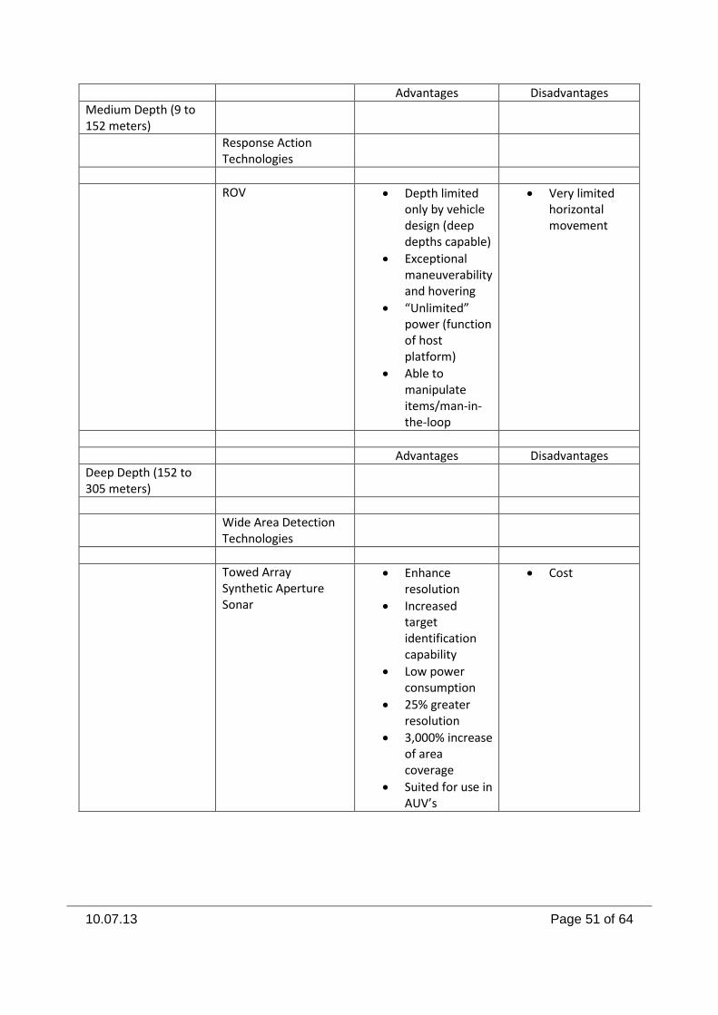
10.07.13 Page 51 of 64
Advantages Disadvantages
Medium Depth (9 to 152 meters)
Response Action Technologies
ROV Depth limited only by vehicle design (deep depths capable)
Exceptional maneuverability and hovering
“Unlimited” power (function of host platform)
Able to manipulate items/man-in-the-loop
Very limited horizontal movement
Advantages Disadvantages
Deep Depth (152 to 305 meters)
Wide Area Detection Technologies
Towed Array Synthetic Aperture Sonar
Enhance resolution
Increased target identification capability
Low power consumption
25% greater resolution
3,000% increase of area coverage
Suited for use in AUV’s
Cost
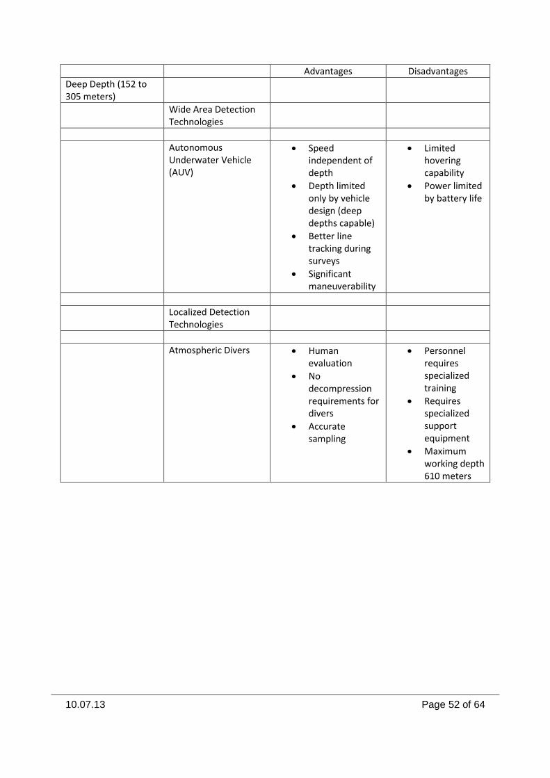
10.07.13 Page 52 of 64
Advantages Disadvantages
Deep Depth (152 to 305 meters)
Wide Area Detection Technologies
Autonomous Underwater Vehicle (AUV)
Speed independent of depth
Depth limited only by vehicle design (deep depths capable)
Better line tracking during surveys
Significant maneuverability
Limited hovering capability
Power limited by battery life
Localized Detection Technologies
Atmospheric Divers Human evaluation
No decompression requirements for divers
Accurate sampling
Personnel requires specialized training
Requires specialized support equipment
Maximum working depth 610 meters
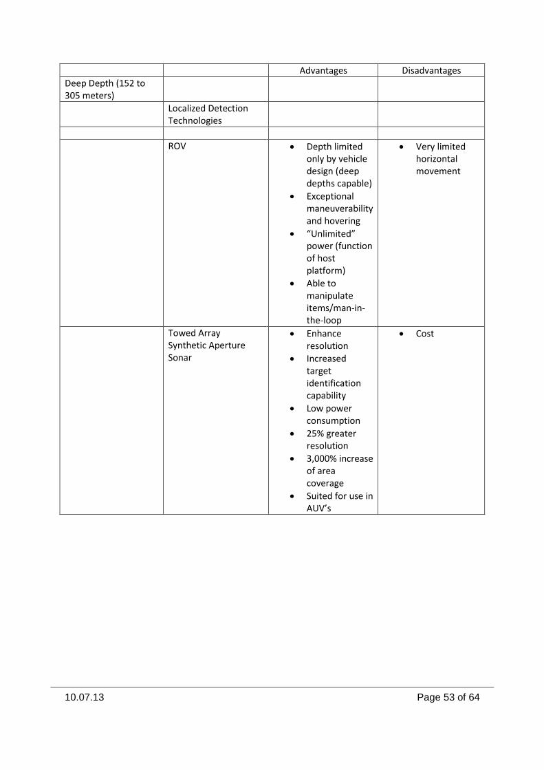
10.07.13 Page 53 of 64
Advantages Disadvantages
Deep Depth (152 to 305 meters)
Localized Detection Technologies
ROV Depth limited only by vehicle design (deep depths capable)
Exceptional maneuverability and hovering
“Unlimited” power (function of host platform)
Able to manipulate items/man-in-the-loop
Very limited horizontal movement
Towed Array Synthetic Aperture Sonar
Enhance resolution
Increased target identification capability
Low power consumption
25% greater resolution
3,000% increase of area coverage
Suited for use in AUV’s
Cost
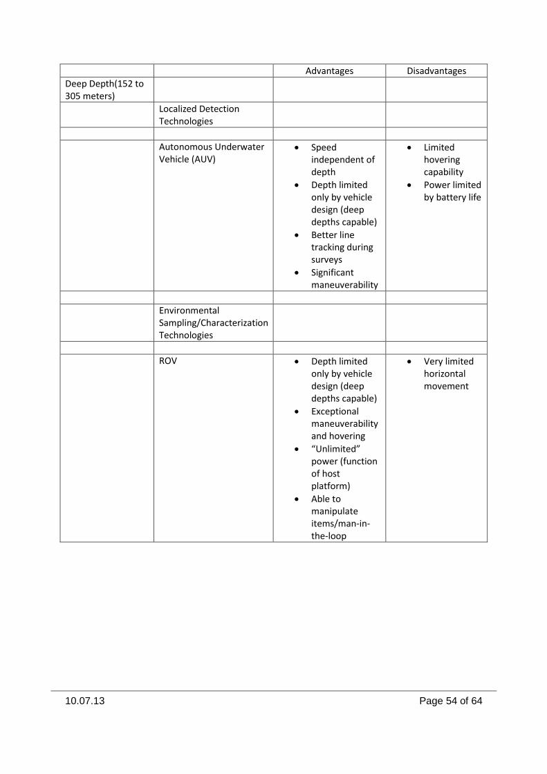
10.07.13 Page 54 of 64
Advantages Disadvantages
Deep Depth(152 to 305 meters)
Localized Detection Technologies
Autonomous Underwater Vehicle (AUV)
Speed independent of depth
Depth limited only by vehicle design (deep depths capable)
Better line tracking during surveys
Significant maneuverability
Limited hovering capability
Power limited by battery life
Environmental Sampling/Characterization Technologies
ROV Depth limited only by vehicle design (deep depths capable)
Exceptional maneuverability and hovering
“Unlimited” power (function of host platform)
Able to manipulate items/man-in-the-loop
Very limited horizontal movement
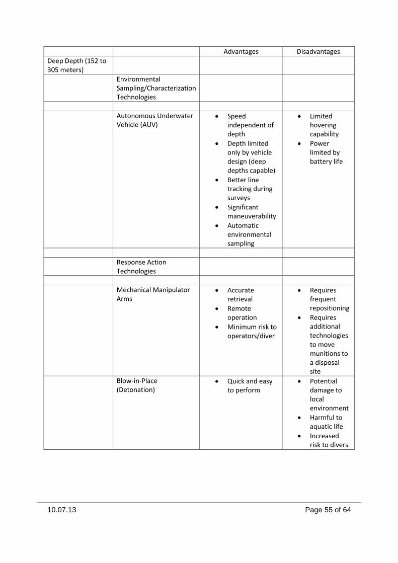
10.07.13 Page 55 of 64
Advantages Disadvantages
Deep Depth (152 to 305 meters)
Environmental Sampling/Characterization Technologies
Autonomous Underwater Vehicle (AUV)
Speed independent of depth
Depth limited only by vehicle design (deep depths capable)
Better line tracking during surveys
Significant maneuverability
Automatic environmental sampling
Limited hovering capability
Power limited by battery life
Response Action Technologies
Mechanical Manipulator Arms
Accurate retrieval
Remote operation
Minimum risk to operators/diver
Requires frequent repositioning
Requires additional technologies to move munitions to a disposal site
Blow-in-Place (Detonation)
Quick and easy to perform
Potential damage to local environment
Harmful to aquatic life
Increased risk to divers
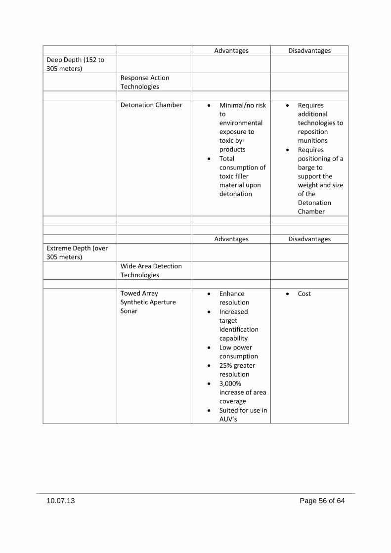
10.07.13 Page 56 of 64
Advantages Disadvantages
Deep Depth (152 to 305 meters)
Response Action Technologies
Detonation Chamber Minimal/no risk to environmental exposure to toxic by-products
Total consumption of toxic filler material upon detonation
Requires additional technologies to reposition munitions
Requires positioning of a barge to support the weight and size of the Detonation Chamber
Advantages Disadvantages
Extreme Depth (over 305 meters)
Wide Area Detection Technologies
Towed Array Synthetic Aperture Sonar
Enhance resolution
Increased target identification capability
Low power consumption
25% greater resolution
3,000% increase of area coverage
Suited for use in AUV’s
Cost
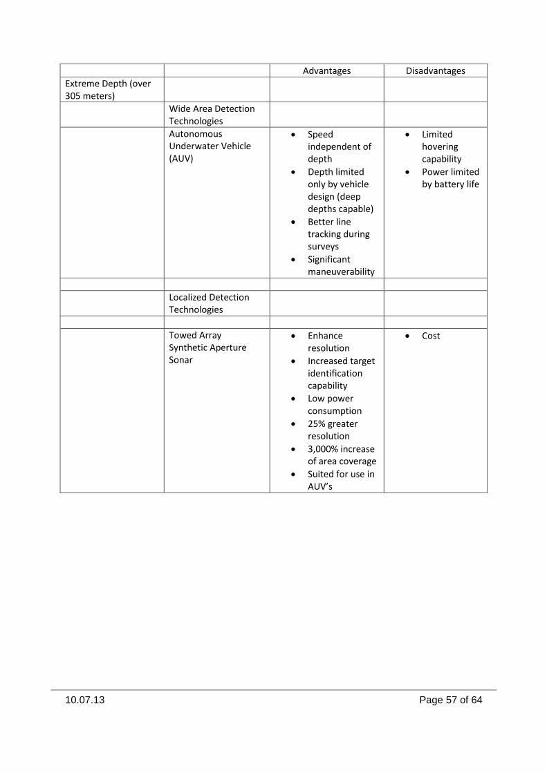
10.07.13 Page 57 of 64
Advantages Disadvantages
Extreme Depth (over 305 meters)
Wide Area Detection Technologies
Autonomous Underwater Vehicle (AUV)
Speed independent of depth
Depth limited only by vehicle design (deep depths capable)
Better line tracking during surveys
Significant maneuverability
Limited hovering capability
Power limited by battery life
Localized Detection Technologies
Towed Array Synthetic Aperture Sonar
Enhance resolution
Increased target identification capability
Low power consumption
25% greater resolution
3,000% increase of area coverage
Suited for use in AUV’s
Cost
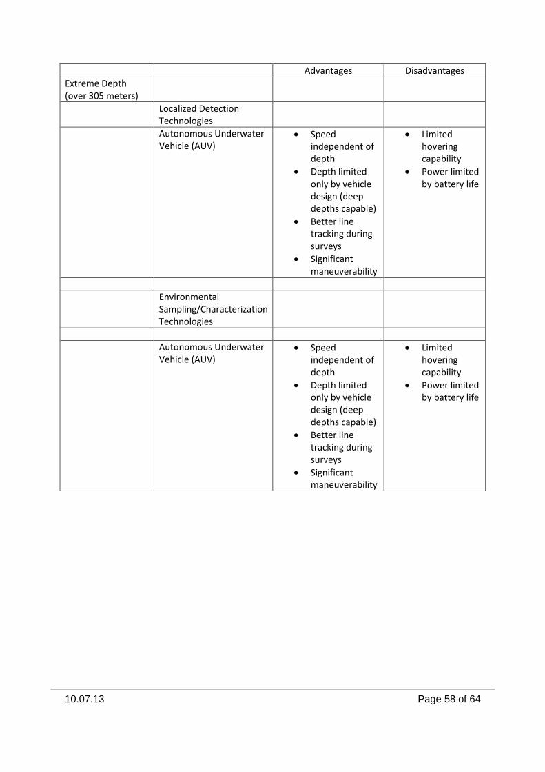
10.07.13 Page 58 of 64
Advantages Disadvantages
Extreme Depth (over 305 meters)
Localized Detection Technologies
Autonomous Underwater Vehicle (AUV)
Speed independent of depth
Depth limited only by vehicle design (deep depths capable)
Better line tracking during surveys
Significant maneuverability
Limited hovering capability
Power limited by battery life
Environmental Sampling/Characterization Technologies
Autonomous Underwater Vehicle (AUV)
Speed independent of depth
Depth limited only by vehicle design (deep depths capable)
Better line tracking during surveys
Significant maneuverability
Limited hovering capability
Power limited by battery life
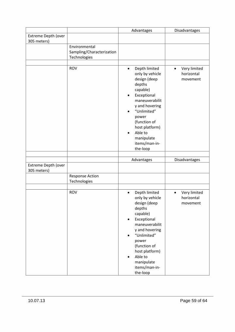
10.07.13 Page 59 of 64
Advantages Disadvantages
Extreme Depth (over 305 meters)
Environmental Sampling/Characterization Technologies
ROV Depth limited only by vehicle design (deep depths capable)
Exceptional maneuverability and hovering
“Unlimited” power (function of host platform)
Able to manipulate items/man-in-the-loop
Very limited horizontal movement
Advantages Disadvantages
Extreme Depth (over 305 meters)
Response Action Technologies
ROV Depth limited only by vehicle design (deep depths capable)
Exceptional maneuverability and hovering
“Unlimited” power (function of host platform)
Able to manipulate items/man-in-the-loop
Very limited horizontal movement
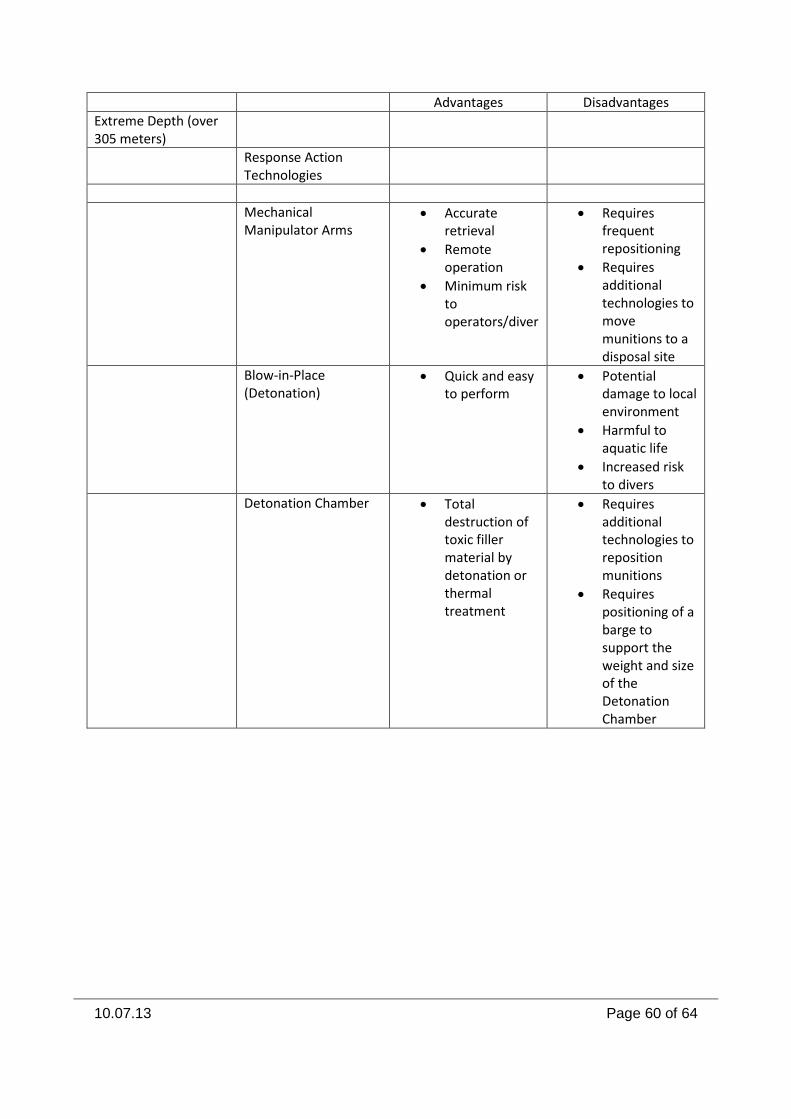
10.07.13 Page 60 of 64
Advantages Disadvantages
Extreme Depth (over 305 meters)
Response Action Technologies
Mechanical Manipulator Arms
Accurate retrieval
Remote operation
Minimum risk to operators/diver
Requires frequent repositioning
Requires additional technologies to move munitions to a disposal site
Blow-in-Place (Detonation)
Quick and easy to perform
Potential damage to local environment
Harmful to aquatic life
Increased risk to divers
Detonation Chamber Total destruction of toxic filler material by detonation or thermal treatment
Requires additional technologies to reposition munitions
Requires positioning of a barge to support the weight and size of the Detonation Chamber
10.07.13 Page 61 of 64
Sources Cited Second Special issue Part I of the Marine Technology Society MTSJ Journal The Legacy of Underwater Munitions Worldwide: Policy and the Science of Assessment, Impacts and Potential Responses. Editors: (Volume 43, Number 4, Fall 2009) Geoffrey Carton and Terrance P. Long Third Special issue Part II of the Marine Technology Society MTSJ Journal The Legacy of Underwater Munitions Worldwide: Policy and the Science of Assessment, Impacts and Potential Responses. Editors: Geoffrey Carton and Terrance P. Long, 2010 Growing Consensus on Sea Dumped Chemical and Conventional Munitions Abandoned in a Marine Environment, Author: Terrance P. Long, Marine Technology Society (MTS) Journal, December 1, 2010. Investing in mutually shared goals.
Data Fuzing of Technology in Autonomous Underwater Vehicles (AUV) for Underwater Munitions Detection, Terrance P. Long, President, Wentworth Environmental Inc, Thomas deWilde, Geophysicist, aDede, Looking for a way to overcome the challenges and limitations of marine UXO surveys, ADEDE and WEI have combined Iver2 Autonomous Underwater Vehicle (AUV) and Side-Scan Sonar (SSS) technology with marine Overhauser magnetometry.
“Paardenmarkt Site Evaluation” Renard Center of Marine Geology, University of Gent, Gent, Belgium SERDP Project UX-1325 “Detection of UXO in Underwater Sites Using Towed Array Resistivity/IP Measurements” Zonge Engineering & Research Organization, Inc., USA Technical Report TR-2088-OCN “Classification and Mapping of Underwater UXO, Naval Facilities Engineering Services Center, USA Underwater Technology Paper, Yu. K. Alekseev, L. V. Akinshina, V. V. Kostenko, Far-Eastern State Technical University, Russia Technical Report “Underwater UXO Detection Systems in Europe”, PhD. Richard J. World, Backhawk GeoServices, USA Technical Paper “Synthetic Aperture SONAR: Frontiers in Underwater Imaging”, Dr. Daniel Sternlicht and Dr. John F. Pesaturo, Dynamics Technology, Inc., USA ESTCP Project MM-0321 “Dredging Equipment Modifications for Detection and Removal of Ordnance” Naval Facilities Engineering Service Center, USA
10.07.13 Page 62 of 64
Technical Paper “An Overview of Underwater Technologies for Operations Involving Underwater Munitions” U.S. Army Corps of Engineers, USA Theoretical Study Report “Developing Magnetometer Techniques to Identify Submerged Archaeological Sites” Historic Environment, Environment, Planning & Economy Cornwall Council, UK SERDP/ESTCP Final Report “SERDP and ESTCP on Technology Needs for the Characterization, Management, and Remediation of Military Munitions in Underwater Environments” SERDP, USA Final Report “UXO Detection and Characterization in the Marine Environment” ESTCP Project MM-0324, ESTCP, USA Technical Paper “DSTO-TN-0354 Removal of Range-dependent Artifacts from Sidescan Sonar Imagery, Maritime Operations Division Aeronautical and Maritime Research Laboratory, USA Final Report “ Vieques Underwater UXO Demonstration Projects VIEQUES ISLAND, PUERTO RICO”, NOAA, USA Technical Paper “Introduction to Synthetic Aperture Sonar” Roy Edgar Hansen, Norwegian Defence Research Establishment, Norway Paper, “Community Perspective on Underwater Munitions Response” Lenny Siegel, Center for Public Environmental Oversight” USA Technical Paper, “Demonstration/Validation of Rapid Chemical Degradation of Reclaimed and Stockpiled Explosive D (Picric Acid-Based Explosives) by MuniRem® at Gradient Technology Facility, Elk River, MN” PLANTECO Environmental Consultants, LLC, USA
Paper, “An Overview of Underwater Technologies for Operations Involving Underwater Munitions” U.S. Army Corps of Engineers, USA Power Point Presentation, “Dredging in Sediment Containing Munitions” Timothy Holland, U.S. Army Corps of Engineers, USA Final Report, “Vieques Underwater UXO Demonstration Projects VIEQUES ISLAND, PUERTO RICO” National Oceanic and Atmospheric Administration (NOAA), USA Memorandum, “Subject: Primer for the Munitions Response Site Prioritization Protocol” Department of Defense, USA
10.07.13 Page 63 of 64
Website Citations http://www.usgs.gov/science/science.php?term=1061 http://www.l-3klein.com/3000series/3000.html http://chartmaker.ncd.noaa.gov/HSD/wrecks.html http://www.subsea.org/index.html http://www.marine-group.com/SonarPrimer/SideScanSonar.htm http://www.cctechnol.com/site41.php http://www.seascape.nl/index.htm http://www.cyberpursuits.com/archeo/uw-arch.asp http://www.soest.hawaii.edu/HMRG/imi30/index.htm http://www.rovworld.com/ http://www.mbari.org/ http://www.whoi.edu/ http://data.nurp.noaa.gov/nurp03/Tech.html http://www.subsea.org/index.html http://www.nuytco.com/ http://www.tritech.co.uk/rental/rental-main.htm http://www.cctechnol.com/site41.php http://www.sub-find.com/index.html http://www.bluefinrobotics.com/ http://www.cctechnol.com/site41.php http://www.silvercrestsubmarines.co.uk/newsletter_jan_2004.html http://www.usgs.gov/science/science.php?term=1061

10.07.13 Page 64 of 64
http://www.subsea.org/index.html http://www.sub-find.com/index.html http://www.sub-find.com/index.html http://www.tarpoondivecenter.com/Merchant2/merchant.mvc?Screen=CTGY&Category_Code=Remote-Submersible-Cameras http://www.tritech.co.uk http://adsabs.harvard.edu http://www.qinetiq-na.com http://amphibia.co.ba/future.php http://www.stormingmedia.us/64/6435/A643583.html http://www.hawaii.edu/pmp/completedProjects.htm http://www.cs.nps.navy.mil/research/eod/ http://www.minwara.org http://www.quantrosensing.com/ http://www.underwatermunitions.org http://www.underwatermunitions.de