Embed Size (px)
Citation preview
IO00 lEEE TRANSACTIONS ON ANTENNAS AND PROPAGATION, VOL. 42. NO. I , JULY 1994
Mutual Coupling Between Rotated Horns Ground Plane
Trevor S. Bird, Senior Member, IEEE, and David G. Bateman, Member, IEEE
Abstruct- Two formulations are presented for the mutual admittance of rotated rectangular apertures in a ground plane. One extends an earlier solution, and the other is a third-order asymptotic formula that is shown to be accurate when the aper- tures satisfy the Rayleigh distance criterion. These formulations are combined with a conventional mode-matching approach to study coupling between rotated horns. Results are presented for both coupling formulations, and these demonstrate excellent agreement with experiment for coplanar pyramidal and sectoral horns.
I. INTRODUCTION
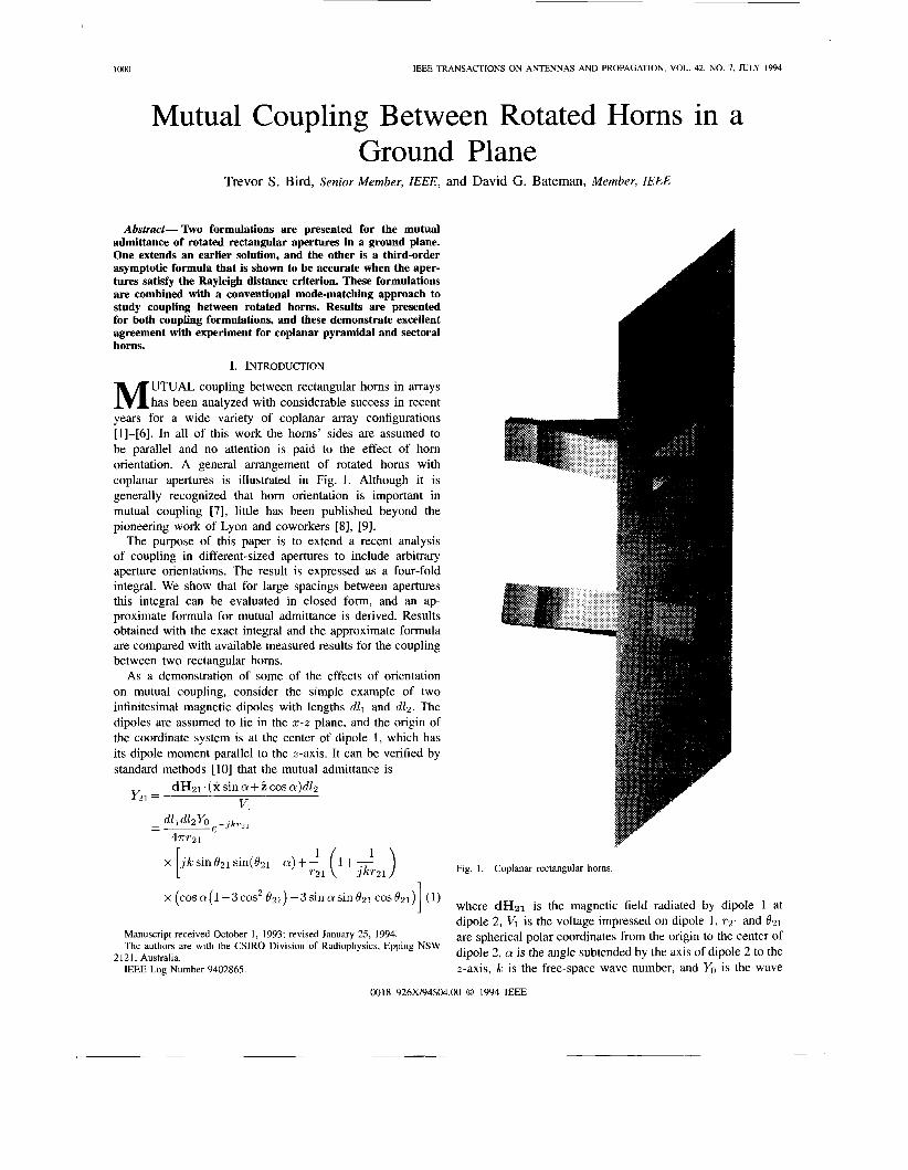
UTUAL coupling between rectangular horns in arrays M has been analyzed with considerable success in recent years for a wide variety of coplanar array configurations [1]-[6]. In all of this work the horns’ sides are assumed to be parallel and no attention is paid to the effect of horn orientation. A general arrangement of rotated horns with coplanar apertures is illustrated in Fig. 1. Although it is generally recognized that horn orientation is important in mutual coupling [7], little has been published beyond the pioneering work of Lyon and coworkers [8], [9].
The purpose of this paper is to extend a recent analysis of coupling in different-sized apertures to include arbitrary aperture orientations. The result is expressed as a four-fold integral. We show that for large spacings between apertures this integral can be evaluated in closed form, and an ap- proximate formula for mutual admittance is derived. Results obtained with the exact integral and the approximate formula are compared with available measured results for the coupling between two rectangular horns.
As a demonstration of some of the effects of orientation on mutual coupling, consider the simple example of two infinitesimal magnetic dipoles with lengths d l l and dl2 . The dipoles are assumed to lie in the 5-2 plane, and the origin of the coordinate system is at the center of dipole 1, which has its dipole moment parallel to the z-axis. It can be verified by standard methods [ 101 that the mutual admittance is
d H ~ l . ( x s i i i a + i c o s c r ) & Vl
Y21= -
x (cos a(1-3 cos’ 021) - 3 sin a sin 021 cos 021) ( 1 ) 1 Manuscript received October I , 1993; revised January 25, 1994. The authors are with the CSIRO Division of Radiophysics, Epping NSW
IEEE Log Number 9402865. 2121, Australia.
in a
Fig. 1. Coplanar rectangular horns
where dH21 is the magnetic field radiated by dipole 1 at dipole 2, VI is the voltage impressed on dipole 1, ~ 2 1 and 021
are spherical polar coordinates from the origin to the center of dipole 2, a is the angle subtended by the axis of dipole 2 to the z-axis, k is the free-space wave number, and Yo is the wave
0018-926X/94$04.00 0 1994 IEEE
BIRD AND BATEMAN: ROTATED HORNS IN A GROUND PLANE 1001
I X 0
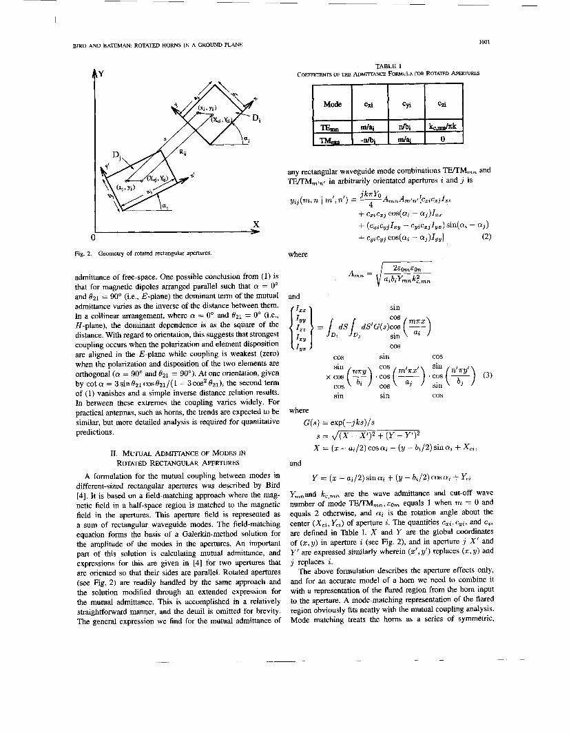
Fig. 2. Geometry of rotated rectangular apertures.
admittance of free-space. One possible conclusion from (1) is that for magnetic dipoles arranged parallel such that a = 0" and f121 = 90" (i.e., E-plane) the dominant term of the mutual admittance varies as the inverse of the distance between them. In a collinear arrangement, where a = 0" and 821 = 0" (i.e., H-plane), the dominant dependence is as the square of the distance. With regard to orientation, this suggests that strongest coupling occurs when the polarization and element disposition are aligned in the E-plane while coupling is weakest (zero) when the polarization and disposition of the two elements are orthogonal (a = 90" and 821 = 90"). At one orientation, given by cot a = 3sinOZ1 c 0 s f l ~ ~ / ( 1 - 3cos2 flZ1), the second term of (1) vanishes and a simple inverse distance relation results. In between these extremes the coupling varies widely. For practical antennas, such as homs, the trends are expected to be similar, but more detailed analysis is required for quantitative predictions.
11. MUTUAL A D M ~ ~ ~ A N C E OF MODES IN ROTATED RECTANGULAR APERTURES
A formulation for the mutual coupling between modes in different-sized rectangular apertures was described by Bird [4]. It is based on a field-matching approach where the mag- netic field in a half-space region is matched to the magnetic field in the apertures. This aperture field is represented as a sum of rectangular waveguide modes. The field-matching equation forms the basis of a Galerkin-method solution for the amplitude of the modes in the apertures. An important part of this solution is calculating mutual admittance, and expressions for this are given in [4] for two apertures that are oriented so that their sides are parallel. Rotated apertures (see Fig. 2) are readily handled by the same approach and the solution modified through an extended expression for the mutual admittance. This is accomplished in a relatively straightforward manner, and the detail is omitted for brevity. The general expression we find for the mutual admittance of
TABLE I COEFFICIENTS OF THE h M l l T A N C E FORMULA FOR ROTATED APEA TURES
and
f Izx > sin
cos sin cos sin cos sin
cos sin sin cos
where G(s) = exp(-jks)/s
s = J(X - X')2 + (Y - Y')2 X = (xCai /2)cosa i - (y-b i /2)s ina i+XCi ,
and
Y = (x - ai/2) sin ai + (y - b;/2) cos a; + Yc;
Ymnand kc,mn are the wave admittance and cut-off wave number of mode TE/TM,, , equals 1 when m = 0 and equals 2 otherwise, and a; is the rotation angle about the center (Xc i , Yci) of aperture i. The quantities czi , cyi, and c,i are defined in Table I. X and Y are the global coordinates of (x,y) in aperture i (see Fig. 2), and in aperture j X' and Y' are expressed similarly wherein (XI, y') replaces (2, y) and j replaces i.
The above formulation describes the aperture effects only, and for an accurate model of a hom we need to combine it with a representation of the flared region from the hom input to the aperture. A mode-matching representation of the flared region obviously fits neatly with the mutual coupling analysis. Mode matching treats the homs as a series of symmetric,
1002 IEEE TRANSACTIONS ON ANTENNAS AND PROPAGATION, VOL. 42, NO. 7, JULY 1994
s.. u - -
double-plane waveguide steps, and the scattering matrix for each discontinuity is calculated and combined in a way that is now standard for individual horn analysis [5], [ll]-[13]. The model of the complete horn is then constructed by combining the scattering matrixes of the individual steps. Let S(k) be the mode-scattering matrix of horn k . The ( i , j ) partition of the overall mode scattering matrix without aperture coupling is
-si;) 0 0 . 0 s p 0 . . . 0 0 s p .. . (4)
The final part of the analysis combines this matrix with the mode-scattering matrix for the apertures, S(’), that is computed from the mode admittances (see [4, (4)]). Assume modes of amplitude a1 are input to the horns. The amplitude of the modes exiting at the horn inputs is given by [5]
bI = [Sll + S12S(’)(U - S22S(o))-1S21]a~ (5)
where U is the unitary matrix. Therefore, the outputs of an array of horns, given by (5), is a combination of reflected modes and modes generated by mutual coupling.
The four-fold integrals in (3) must be evaluated numeri- cally. For this purpose we have developed an efficient one- dimensional adaptive quadrature scheme based on Simpson’s rule [14]. This rule subdivides the integration region into smaller intervals and arranges quadrature on these intervals in terms of their contribution to the total error. The interval with the largest contribution to the error is subdivided first until a specified accuracy is met. Each subinterval is considered in turn, and this results in a binary tree of estimates to the integral. To speed convergence, all previously calculated values are reused in the next level quadrature rule. Multidimensional integrals are evaluated recursively using multiple calls to the one-dimensional scheme.
111. ASYMFTOTIC FORMULA FOR MUTUAL ADMITTANCE
Computation of the mutual admittance by direct numerical integration is time consuming for large arrays. It is there- fore advantageous to have available an approximate formula for calculating admittance, especially when the apertures are widely separated; after all, in arrays this is the most common situation. There are several possible ways of obtaining such expressions. The one adopted here is to expand the free-space Green’s function in a Taylor series in the manner outlined by Bird [15]. Once this is done the integrals in I zz , etc., can be integrated in closed form.
Now suppose the two apertures in Fig. 2 are sufficiently far apart such that
where (xi, yi) are referred to the center of aperture i. The implication is that the aperture spacing should be much greater than the largest aperture dimension that is projected normal
to the line drawn between the origins of the apertures. This fur-jeld assumption allows the scalar Green’s function to be expanded as a Taylor series in the aperture’s center spacing Rz,. To terms of third order, this is
G(s) G(R,,)exp(-jkv)
1 + (6)
where v = R;j. A , w = A . A and A = Ri - Rj = X(x - 2’) + y(y - y’).
Substitute (6) in (3) to obtain
n
where -a12 -a12 - b / 2 - b / 2
upq = s dxi .? dx, dy; af2 a f2 b f 2 b f 2
z j a j
x d y j ( X - X’)P(Y - Y’)qx x exp[-jk(cos B(X - X ’ ) + sin B(Y - Y’))]
sin cos cos sin
sin cos x cos + ?)) .cos ( + a))
cos sin
sin cos
cos sin cos . c o s ( 9 ( . + + ) ) . sin (8)
sin cos
The subscripts p and v in (7) correspond to the subscripts 2, y and z in (3). ( X , Y ) and (X’ ,Y’ ) are the global coordinates in apertures i and j. The functions upq can be evaluated in closed form as shown in the Appendix. They comprise sums of permutations of other functions that are products of one- dimensional Fourier transforms of powers and trigonometric functions. It is shown in the Appendix that these transforms are recursive functions and, therefore, they are computed very quickly. We have derived all functions shown in (7) and the first five of these are listed in the Appendix. Further,
BIRD AND BATEMAN ROTATED HORNS IN A GROUND PLANE 1003
-30
Exad- ksymptotic ----
U
-80 - -90 -
-100 -
-1 10 I I 1 I
0 5 10 15 20 SePdm (U
(a)
Exad- hympotic ----. -
4 0 -
-50
h
8 -60-
-70
-80 -
-90
-100
-
-
- -
5
-110 ' I I I I I 0 5 10 15 m 25
sepantion (U
(b)
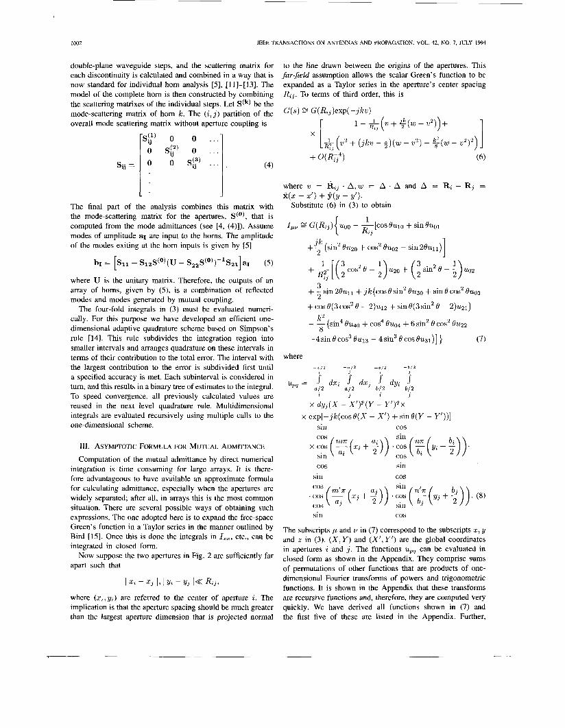
Fig. 3. Coupling of square waveguides as a function of waveguide center separation and sidelength (a). (a) E-plane; (b) If-plane.
it may be shown that uqp is obtained from upq by making the following substitutions, while keeping all other variables in upn fixed: cosai 4 sina; ,cosaj -+ s ina j , s ina i -+
-cosa; ,s inaj + -cosaj . The present asymptotic formula, which is (2) in association
with (7), is a generalization of earlier far-field approximations for aperture coupling. For example, Hockham developed a formula applicable to unrotated apertures that is accurate to second order (i.e. uses the first line of (7)) [ 161. Earlier, Lyon et al. [9] derived the second-order formula for rotated apertures. There is a simple physical interpretation for the asymptotic formula. It is approximately the mutual admittance of two
-15 I I I I I I I I I
-50 ' I I I 1 I I I I 0 10 U) 30 40 50 60 70 80
RotatimAngle (W)
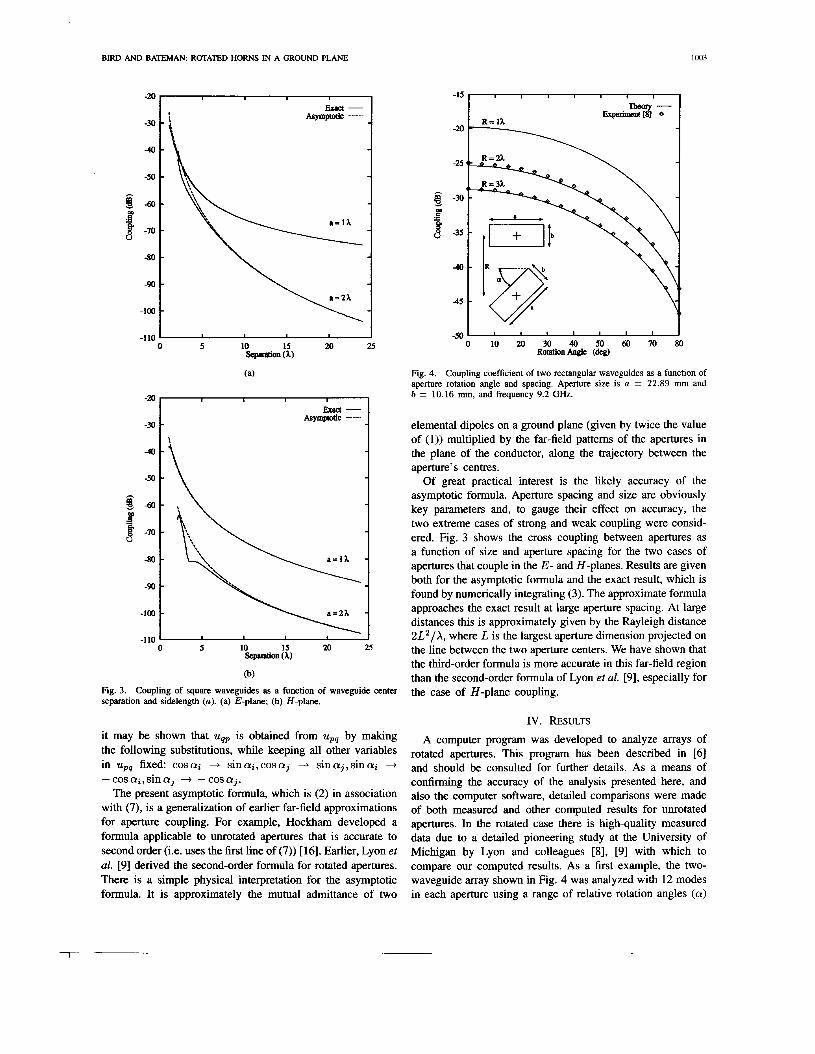
Fig. 4. Coupling coefficient of two rectangular waveguides as a function of aperture rotation angle and spacing. Aperture size is a = 22.89 mm and b = 10.16 mm, and frequency 9.2 GHz.
elemental dipoles on a ground plane (given by twice the value of (1)) multiplied by the far-field patterns of the apertures in the plane of the conductor, along the trajectory between the aperture's centres.
Of great practical interest is the likely accuracy of the asymptotic formula. Aperture spacing and size are obviously key parameters and, to gauge their effect on accuracy, the two extreme cases of strong and weak coupling were consid- ered. Fig. 3 shows the cross coupling between apertures as a function of size and aperture spacing for the two cases of apertures that couple in the E- and H-planes. Results are given both for the asymptotic formula and the exact result, which is found by numerically integrating (3). The approximate formula approaches the exact result at large aperture spacing. At large distances this is approximately given by the Rayleigh distance 2L2/X, where L is the largest aperture dimension projected on the line between the two aperture centers. We have shown that the third-order formula is more accurate in this far-field region than the second-order formula of Lyon et al. [9], especially for the case of H-plane coupling.
IV. RESULTS A computer program was developed to analyze arrays of
rotated apertures. This program has been described in [6] and should be consulted for further details. As a means of confirming the accuracy of the analysis presented here, and also the computer software, detailed comparisons were made of both measured and other computed results for unrotated apertures. In the rotated case there is high-quality measured data due to a detailed pioneering study at the University of Michigan by Lyon and colleagues [8], [9] with which to compare our computed results. As a first example, the two- waveguide array shown in Fig. 4 was analyzed with 12 modes in each aperture using a range of relative rotation angles (a)
1004 IEEE TRANSACTIONS ON ANTENNAS AND PROPAGATION, VOL. 42, NO, 7, JULY 1994
I I \ I I H-planecoupling
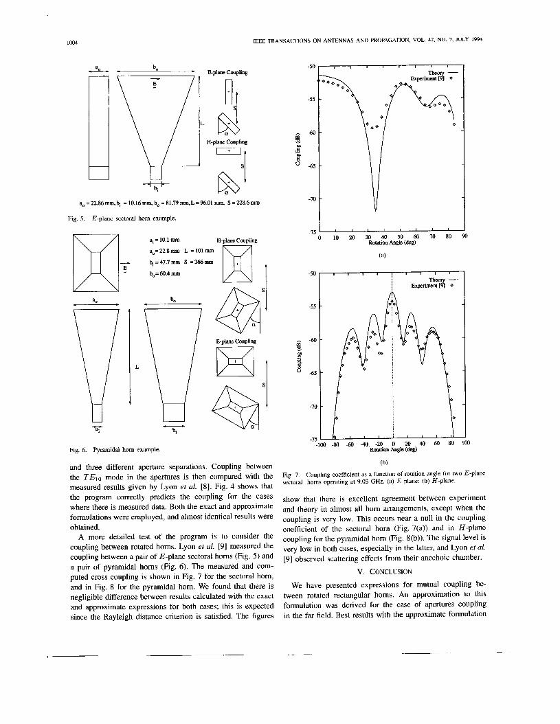
ao=22.86mm,$ =10.16nun,bo=81.79nun,L=96.01 mm, S=228.6nun
Fig. 5. E-plane sectoral horn example.
L
ai = 10.1 nun
ao= 22.8 mm L = 101 nun
bi=47.7nun S =366"
H-plane Coupling
D bo= 60.4 nun
E-plane Coupling
Fig. 6. Pyramidal horn example.
and three different aperture separations. Coupling between the TElo mode in the apertures is then compared with the measured results given by Lyon et al. [8]. Fig. 4 shows that the program correctly predicts the coupling for the cases where there is measured data. Both the exact and approximate formulations were employed, and almost identical results were obtained.
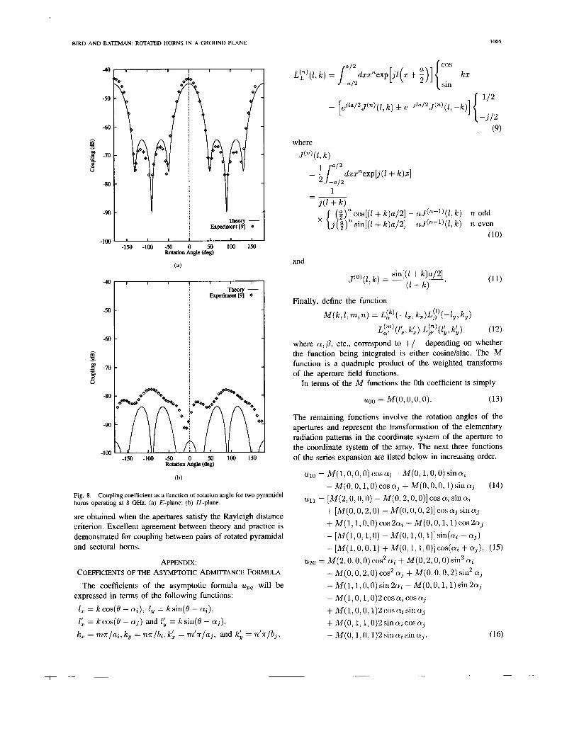
A more detailed test of the program is to consider the coupling between rotated homs. Lyon et al. [9] measured the coupling between a pair of E-plane sectoral homs (Fig. 5) and a pair of pyramidal homs (Fig. 6) . The measured and com- puted cross coupling is shown in Fig. 7 for the sectoral horn, and in Fig. 8 for the pyramidal hom. We found that there is negligible difference between results calculated with the exact and approximate expressions for both cases; this is expected since the Rayleigh distance criterion is satisfied. The figures
-50
-55
-60
-65
-70
-75
-50
-55
-60 !s m a e. 8
-65
-70
-75
I I I I I ' ' I
10 20 30 40 50 60 70 80 90 Rotation Angle (deg)
(a)
, l 1 l l l l
Theory - j Experiment [91 Q
) -80 -60 -40 -20 0 20 40 60 80 100 Rotation Angle (deg)
(b)
Fig. 7. sectoral horns operating at 9.03 GHz. (a) E-plane; (b) H-plane.
show that there is excellent agreement between experiment and theory in almost all hom arrangements, except when the coupling is very low. This occurs near a null in the coupling coefficient of the sectoral hom (Fig. 7(a)) and in H-plane coupling for the pyramidal hom (Fig. S(b)). The signal level is very low in both cases, especially in the latter, and Lyon et al. [9] observed scattering effects from their anechoic chamber.
V. CONCLUSION
Coupling coefficient as a function of rotation angle for two E-plane
We have presented expressions for mutual coupling be- tween rotated rectangular homs. An approximation to this formulation was derived for the case of apertures coupling in the far field. Best results with the approximate formulation
BIRD AND BATEMAN: ROTATED HORNS IN A GROUND PLANE
-50
-60 -
4
-50
-60
8 B 3 -70
V
-80
-90
-100
4 1 I I I I I I
Theory - i Experimnt[9]
-
I I I
Experiment [9] e
-1% -100 -50 0 50 100 150 Rotation Angle (de&
(a)
-150 -100 -50 0 50 100 150 Rotation Angle (de@
Fig. 8. horns operating at 8 GHz. (a) E-plane; (b) H-plane.
are obtained when the apertures satisfy the Rayleigh distance criterion. Excellent agreement between theory and practice is demonstrated for coupling between pairs of rotated pyramidal and sectoral horns.
Coupling coefficient as a function of rotation angle for two pyramidal
APPENDIX: COEFFWIENTS OF THE ASVMITOTIC ADMIITANCE FORMULA
The coefficients of the asymptotic formula upq will be expressed in terms of the following functions:
1, = kcos(8 - ai), 1, = ksin(8 - ai),
1; = kcos(8 - aj ) and 1; = ksin(8 - aj) .
k, = mr/a;, k, = nr/b;, k: = m ' r / a j , and k; = n ' r / b j ,
(9) where
J(")(Z, k )
and sin[(l + k)a/2]
@ + k ) '
J(O)(Z, k ) =
Finally, define the function
M ( k , 1, m, n) = L p ( -1,, kz)L;'( -1,, k,)
L y ( z ; , k;) L;)(l;,Ic;) (12)
where a,P, etc., correspond to +/- depending on whether the function being integrated is either cosinekine. The M function is a quadruple product of the weighted transforms of the aperture field functions.
In terms of the M functions the 0th coefficient is simply
U00 = M(O,O, 0,O). (13)
The remaining functions involve the rotation angles of the apertures and represent the transformation of the elementary radiation patterns in the coordinate system of the aperture to the coordinate system of the array. The next three functions of the series expansion are listed below in increasing order.
u10 = M(I,O, 0, 0) cos ai - M(O, 1 , O , 0) sin a;
u11 = [M(2,0,0,0) - M(O,2,0, o)] cos a; sin a; - M(0 , 0, I, 0) cos aj + M ( 0 , 0, 0,1) sin aj
+ [M(O, 0,2,0) - M(O,O, 0,2)] cos aj sin aj
- [M(I,O,I,O) -M(O,1 ,0 ,1) ]s in(a ;+a j )
(14)
+M(l , l ,O,0)cos2a ; +M(O,O,1, l )cos2aj
- [M(1,O, 0,1) + M(O, 1,1, O)] COS(^; + aj ) , (15)
u20 = M ( ~ , o , O , O ) cos2 a; + M ( O , ~ , o , o ) sin2 a; + M ( O , 0,2,0) cos2 aj + M ( O , O , O , 2) sin2 aj
-M(l l1 ,0 ,O)s in2a ; -M(O,O,I , l ) s in2a j - M ( 1,0,1,0)2 cos a; cos aj
+ M ( 1,0,0,1)2 cos a; sin aj
+ M(O, 1,1,O)2 sin a; cos aj
- M(O, 1 , O , l )2 sin a; sin aj.
1006 IEEE TRANSACTIONS ON ANTENNAS AND PROPAGATION, VOL. 42, NO. I, JULY 1994
u01 and u02 are obtained from u10 and u20 by replacing ai with ai - T / 2 in (14) and (16)-but note, not in the M func- tions. Expressions have been derived for u30,2121, U401 u317
[14] M. A. Malcolm and R. B. Simpson, “Local versus global strategies for adaptive quadrature,” ACM Trans. on Math. Software, vol. 1, pp. 129-146, 1975.
[IS] T. S. Bird, “Mode coupling in a planar circular waveguide array,” IEE ~~
and 2 ~ 2 2 , using the symbolic mathematics package Maple V
listed here. If required, they may be obtained on request from
J. Microwaves Opt. Acoust;, vol. 3 , pp. 172-180, Sept. 1979.
antenna,” in Proc. European Microwave Con$, Brussels, Belgium, Sept. 4-7, 1973, PaOer C.1.3.
[17]. As these equations are lengthy they are not [I61 G. A. H O d h m and G. H. Walker, ‘‘Study of a finite Phased array
the authors.
ACKNOWLEDGMENT
The authors thank J. A . M. Lyon for supplying [9].
REFERENCES
J. Luzwick and R. F. Harrington, “Mutual coupling analysis in a finite planar rectangular waveguide antenna array,” Electromagnetics, vol. 2, pp. 25-42, 1982. A. J. Fenn, G. A. Thiele, and B. A. Munk, “Moment method analysis of finite rectangular waveguide phased arrays,’’ IEEE Trans. Antennas Propagat., vol. 30, pp. 554-564, July 1982. F. Amdt et al., “Generalized moment method analysis of planar re- actively loaded rectangular waveguide arrays,’’ IEEE Trans. Antennas Propagat., vol. 37, pp. 329-338, Mar. 1989. T. S. Bird, “Analysis of mutual coupling in arrays of different-sized rectangular waveguides,” IEEE Trans. Antennas Propagut., vol. 38, pp. 166-172, Feb. 1990. -, “Mode matching analysis of arrays of stepped rectangular homs and application to satellite antenna design,” in Proc. ICAP ’91, IEE Con$ Antennas and Propagafion, University of York, UK, Apr. 1991, pp. 849-852. T. S. Bird and D. G. Bateman, “Software for modelling finite arrays of rectangular waveguides or homs with mutual coupling,” in Proc. IEEE Antennas t Propag. Symp., Chicago, July 18-25, 1992, pp. 633-636. R. C. Hansen, Ed., Microwave Scanning Antennas. New York: Aca- demic, 1966, vol. 2, Ch. 2. J. A. M. Lyon, C. J. Digenis, and W. W. Parker, “Interference reduction methods for antennas on aerospace vehicles,” in Proc. 9th IEEE Electromagnetics Compat. Symp., pp. 82-95, 1967. J. A. M. Lyon et ul., “Derivation of aerospace antenna coupling-factor interference prediction techniques,” Radiation Lab., Univ. of Michigan, Tech. Rep. AFAL-TR-6657, Apr. 1966, AD-483061. S. A. Schelkunoff and H. T. Friis, Antennas: Theory and Practice. New York: Wiley, 1952, Sec. 5.20. G. L. James, “Analysis and design of TE11 -to-HEll corrugated cylindri- cal waveguide mode converters,” IEEE Trans. Microwave Theory Tech., vol. MTT-29, pp. 1059-1066, Oct. 1981. H. Patzelt and F. Amdt, “Double-plane steps in rectangular waveguides and their application for transformers, irises, and filters,” IEEE Trans. Microwave Theory Tech., vol. MTl-30, pp. 771-776, May 1982. E. Kuhn and B. K. Watson, “Rectangular corrugated horns-Analysis, design and evaluation,” in Proc. 14th European Microwave Con$, Sept. 1984, pp. 221-227.
[I71 B. W. Chan-ei al., Maple V Language Reference Manual. New York: Springer, 199 1.
Trevor S. Bird (S’71-M’7&SM’85) received the B.App.Sc., M.App.Sc., and Ph.D. degrees in 1971, 1973, and 1977, respectively, all from the University of Melbourne, Melbourne, Australia.
After two years (1976-1978) as a Postdoctoral Research Fellow at Queen Mary College, Univer- sity of London, London, UK, he spent five years (1978-1983) as a Lecturer in the Electrical En- gineering Department at James Cook University, North Queensland, Australia. He was a Consultant at Plessey Radar PLC, UK, in 1982 and 1983, and he
joined the CSIRO Sydney, Australia, at the end of 1983 as a Senior Research Scientist. He is currently Research Manager of the Electromagnetics and Antennas Program at the CSIRO. At CSIRO, his research includes antennas and components for satellite communications, antenna arrays, shaped-beam antennas, electromagnetic field analysis, and near-field measurement methods.
Dr. Bird is a Fellow of the Institution of Engineers, Australia, and of the Institution of Electrical Engineers (UK). Awards he has received include the John Madsen Medal in 1988 and again in 1992 from the Institution of Engineers, Australia, and a CSIRO Medal in 1990 for development of the Westem Australian antenna system for AUSSAT-B.
David G. Bateman (M’92) was born in 1966 in Wagga, Australia. He received the B.Sc. (Hons.) and B.E. (Hons.) degrees in electrical engineering from the University of Sydney, Sydney, Australia, in 1988 and 1990, respectively. He is currently pursuing the Ph.D. degree at the University of Technology, Sydney, Australia.
From 1991 to early 1994 he was with the Elec- tromagnetics and Antennas Program of the CSIRO Division of Radiophysics, Sydney, Australia. His ar- eas of interest include antennas and components for
satellite- and earth-based microwave systems, electromagnetic field analysis, and scattering.