Embed Size (px)
Citation preview

TECHNICAL SPECIFICATION FOR
SPS REFITTING
MV “OGS EXPLORA”
Client:
Istituto Nazionale di Oceanografia e Geofisica Sperimentale - (TS) Italy
Id. Doc.: C24.14.BK.002
Rev. B
MEDEA Srl
Marine Design & Consulting
Via Campi Flegrei, 34
80078 Pozzuoli (NA) – Italy

Rev. A www.medeadesign.com page 2 of 33
BLANK PAGE

Rev. A www.medeadesign.com page 3 of 33
B 13.03.2015 Issue after OGS meeting- 12.03.2015
(See Ch.5 and Par.6.2)
ML GR GR
A 13.02.2015 First issue ML GR GR
Rev Date Description Issued Checked Approved

Rev. A www.medeadesign.com page 4 of 33
ABBREVIATIONS
Sub- Contractor = All parties contracted by the Builder to perform services and/or deliveries
for the construction of the ship.
GA = General Arrangement Plan.
C.S. = Classification Society.
S.A. = Statutory Authorities
M.C.R.= Maximum Continuous Rating
ISO = International Organization of Standardization.
IMO = International Maritime Organization
E.R. = Engine Room
SB = Starboard
PS = Portside
DB = Double bottom
ROV = Remote operated vehicle
HPU = Hydraulic power unit
DN = Diameter nominal
AC = Air condition
CCTV = Closed circuit television
OCS = Operations control station
PCC = Pipe control console
ECDIS= Electronic chart display information system
MAS = Monitoring and alarm system
PCA = Process control system
PMS = Power management system
DP = Dynamic positioning
VSD = Variation speed drive
VDR = Voyage data recorder
IAS = Integrated automation system
VO = Variation order
MCB = Moulded case breaker
MCCB = Moulded case circuit breaker
SVC = Vessel control system
PABX = Private automatic branch exchange
UPS = Uninterruptible Power Supply
IWO = In way of

OGS Techncial Specification Doc. N. C24.14.BK.002 MV “OGS EXPLORA”
Rev. A page 5 of 33
Table of Contents
1 GENERAL DESCRIPTION ...................................................................................................... 7
1.1 OVERVIEW .......................................................................................................................... 7
1.2 ARRANGEMENT, DESCRIPTION....................................................................................... 7
1.3 MAIN PARTICULARS ........................................................................................................ 10
1.4 CLASS, REGULATIONS, CERTIFICATES ........................................................................ 11
1.5 DRAWINGS ....................................................................................................................... 12
1.6 MATERIALS ....................................................................................................................... 13
1.7 BUILDING METHOD AND WORKMANSHIP ................................................................... 13
1.8 TRIM & STABILITY .......................................................................................................... 14
1.9 OWNER DELIVERIES ....................................................................................................... 14
1.10 ROUTINE BY ALTERATIONS ........................................................................................... 14
1.11 CONSTRUCTION SCHEDULE .......................................................................................... 15
2 MAIN GROUP A – ACCOMMODATION ............................................................................ 16
2.1 GENERAL........................................................................................................................... 16
2.2 STEEL & ALUMINIUM WORKS ........................................................................................ 17
2.3 PAINT WORKS .................................................................................................................. 19
2.4 INSULATION WORKS ...................................................................................................... 19
2.5 CABINS, LABORATORIES AND COMMON SPACES ....................................................... 21
2.6 EXTERNAL FITTINGS ...................................................................................................... 23
2.7 ELECTRICAL SYSTEM ...................................................................................................... 23
2.8 PIPING SYSTEMS ............................................................................................................. 25
2.9 HVAC SYSTEM ..................................................................................................................... 26
2.10 LIFE SAVING APPLIANCES & FIRE FIGHTING EQUIPMENT ....................................... 27
3 MAIN GROUP B – ENGINE ROOM & OTHER MACHINERY SPACES...................... 28
3.1 OVERVIEW ........................................................................................................................ 28
3.2 STEEL WORKS .................................................................................................................. 28
3.3 INSULATION WORKS ...................................................................................................... 28
3.4 PIPE WORKS ..................................................................................................................... 28
4 MAIN GROUP C – HULL ....................................................................................................... 29
4.1 CARGO HOLD ................................................................................................................... 29
4.2 STABILITY ........................................................................................................................ 29
4.3 OPEN DECKS – WORK AREA ........................................................................................... 30
5 MAIN GROUP D – CARGO AND EQUIPMENT HANDLING SYSTEMS .................... 31
5.1 ROSETTE A-FRAME ......................................................................................................... 31
5.2 CARGO CRANE ................................................................................................................ 31
5.3 AFT A-FRAME .................................................................................................................. 32
6 MAIN GROUP E – ELECTRICAL & MACHINERY SYSTEMS ....................................... 33
6.1 STATUTORY REQUIREMENTS ........................................................................................ 33

OGS Techncial Specification Doc. N. C24.14.BK.002 MV “OGS EXPLORA”
Rev. A page 6 of 33
6.2 BOW THRUSTER REFURBISHMENT ............................................................................. 33

OGS Techncial Specification Doc. N. C24.14.BK.002 MV “OGS EXPLORA”
Rev. A page 7 of 33
1 GENERAL DESCRIPTION
1.1 OVERVIEW
1.1.1 The vessel to be refitted and converted according to general arrangement
(drawing no. C.24.14.G.001-rev.4) and this specification.
1.1.2 The specification below presents the modifications needed for the existing
vessel to meet the compliance with IMO Resolution A.534(13) – SPS CODE
and the the general market, for safe and economic World wide service (acc. to
class notation and Owners’ request).
1.1.3 The construction and fitting out of the vessel shall be carried out in accordance
with the best practice at high standard shipBuilder s, with safe operation and
simple maintenance as important guidelines.
1.1.4 In the following, the Buyer, his staff and those who work for him in connection
with this vessel, will be mentioned as the Owners.
1.1.5 The Builders with staff and contractors are mentioned as the Builder. Registro
Italiano Navale (RINA) will be mentioned as the Class, and Comando Generale
del Corpo delle Capitanerie di Porto d’Italia and its acting regional office will
be mentioned as the Authorities, or other relevant authorities, acting on behalf
of the relevant flag state.
1.1.6 The vessel to be delivered to the owners ready for taking onboard provisions,
stores and crew completely seaworthy.
1.1.7 All items described hereby as pertaining to the modernization and refitting
works, including equipment, is required to be provided, installed and
commissioned by the Builder, unless noted otherwise.
1.2 ARRANGEMENT, DESCRIPTION
1.2.1 The vessel to be refitted and arranged as shown on GA-plan. A narrative
description of the main features for the vessel conversion is given, but not
limited to, below:
1.2.2 Accommodation and Fire Definition
a) All linings, insulation and furniture in the accommodation spaces and
all insulation in machinery spaces, including funnels, to be removed
and replaced as indicated in the drawings Fire Definition Plan (n.
C24.14.S.001);
b) The vessel to be arranged with accommodation for 50 persons as shown
on GA-plan;

OGS Techncial Specification Doc. N. C24.14.BK.002 MV “OGS EXPLORA”
Rev. A page 8 of 33
c) All cabins will be fitted with single tier built-in double bed (i.e. bunk
bed) except the cabin designated to accommodate Master and Chief
Engineer;
d) All cabins will be fitted with a sanitary block except for the four cabins
on the first lower deck;
e) Existing hospital to be converted in a sick bay and a dry provision store;
f) Existing dry provision store to be converted in gymnasium
g) Stairway trunking in accommodation spaces to be fire-tight according
to drawing Fire Definition Plan (n. C24.14.S.001);
h) Existing store on 2nd lower deck between fr 55 and 68 to be split in two
parts, fore part of the store to be fitted with a handling room as shown
on GA-plan;
i) Existing goods lift at frame 55-57, electrical and mechanical parts to be
refurbished, doors at each level to be replaced with fire approved type
door as shown in the drawing Fire Definition Plan (n. C24.14.S.001);
j) Existing radio room with all equipment and cabling to be moved on the
bridge;
k) Existing transversal partition at frame 62 on the bridge to be open in
order to have a common open area on the bridge;
l) A vertical trunk for cabling and ducting purposes to be provided
between fr 57 and 58 throughout all accommodation spaces;
m) Three watertight sliding doors, type approved, to be installed according
to drawing C24.14.H.005. All power and electrical installation to be
according SOLAS;
n) New steel means of escape (emergency exits) to be installed according
to drawing no. C24.14.H.004;
o) All windows in accommodation spaces to be moved according to GA,
existing holes to be fairly inserted (Alumium or Steel, according to the
location);
p) New weather-tight door, type approved, to be installed on main deck
i.w.o. mess room, starboard side;
q) Colours of panels, flooring, ceiling, furniture, upholsteries to be agreed
with Owners representative. In particular existing mess room shall be
renewed by keeping as unaltered as possible the original wood-style
appearance;

OGS Techncial Specification Doc. N. C24.14.BK.002 MV “OGS EXPLORA”
Rev. A page 9 of 33
r) Galley to be fitted with two fire type approved rolling shutters, one
serving the self service area in mess room and one for cafeteria, the
latter existing dimension to be reduced to min 600mm;
1.2.3 Hull & Structural
s) Cargo hold to be split in two parts by means of installation on a new
watertight steel bulkhead, at frame 81-82, as indicated in GA and
drawing n. C24.14.H.003;
t) Forward cargo hold to be provided by two new bilge wells (drawing n.
C24.14.H.006) with all necessary fittings (strainers, high-level alarms,
etc.) and valves to be connected to the existing bilge system;
u) Shortening of the existing hatch opening and coamings according to
drawing C24.14.H.002 and in order to stow one ISO 20 container;
v) Provision and installation of a new hatch cover, lift-away type
approved, consisting in at least two panels;
w) Steel insert on main deck and 1st lower deck to restore deck continuity
after shortening of hatch opening;
x) Modification of the movable patch in cargo hold on fist lower deck
according to C24.14.H.002;
y) Modification of the existing A-frame SWL 20tons, by lengthening of
the legs up to 7000mm and replacement of the upper transverse to reach
overall beam of 11000, SWL to be de-rated accordingly;
z) Installation of fixed ballast weights in double bottoms for an aggregate
weight of 34000 kg at x=33.00m, y=0.00, z=0.3m above base line;
aa) A fore mast to be fitted to carry the statutory lights and signals;
bb) Sea fastening devices, twist lock type, to be installed on forward
weather deck in order to carry 1 off ISO20 container on hatch covers
and 1 off ISO10 Containers on deck between frames 72 and 80,
starboard side;
cc) A platform made of steel suitable steel profiles and twist lock to be
installed as extension of deck B (ponte cabine) in order to fit 1 off
ISO20 and 1 off ISO10 Containers;
dd) New platforms on aft open deck to be installed, on portside and
starboard side, to extend transversally the working area; new structures
will be fabricated and installed by the builder as shown in drawing no.
C24.14.H.007;
1.2.4 Machinery and Piping

OGS Techncial Specification Doc. N. C24.14.BK.002 MV “OGS EXPLORA”
Rev. A page 10 of 33
ee) Engine control room to be insulated A60, while existing CO2 in ECR
to be blinded;
ff) Bilge system to be extend in order to serve new forward cargo old as
indicated in the drawing n. C24.14.P.001;
gg) Existing HVAC system to be replaced with new system able to meet
new accommodation arrangement;
hh) Existing thruster to be refurbished by replacing electrical power
components with new system provided frequency converter and new
control system including bridge control panel;
ii) All piping for domestic use in accommodation shall be of new
installation and done by the Builder according to accommodation lay-
out and GA plan;
1.2.5 Additional Items
jj) Removal of the existing derrick crane with all related winches on main
deck and forecastle deck, and installation of a hydraulic crane SWL
3.33ton at 15m (50tm);
kk) Provision and installation of side A-frame at location between fr 72 and
80, starboard side, SWL 5t, fitted with all necessary hydraulic units and
winch fitted with 6000mt dia12mm steel wire and fitted with slip-ring;
ll) As option new hatch cover, the Builder can propose a flush type hatch
cover, removing existing hatch coamings;
1.3 MAIN PARTICULARS
1.3.1 The modernization works shall not alter the original dimensions of the vessel,
which remains:
Length overall 72,63 m
Length between p.p. 64,40 m
Breadth moulded 11,80 m
Dept. main deck midship 6,55 m
Max. draft midship(DWL) 4,42 m
Depth shelter deck 4,15 m

OGS Techncial Specification Doc. N. C24.14.BK.002 MV “OGS EXPLORA”
Rev. A page 11 of 33
1.4 CLASS, REGULATIONS, CERTIFICATES
1.4.1 Hull modifications to be built of steel with full strength to main deck, and to
class RINA 100-A-1.1-Nav IL; ST; IAQ-1; Ice Class IB
1.4.2 The ship is to comply with the rules and regulations of the Authorities in Italy
and the international Load Line Convention. The ship to be classified for
World- wide trade (according to class notation).
1.4.3 The ship also to satisfy latest flag rules and regulations for this special type of
ships in trade and IMO guidelines for design and construction of Offshore
vessels
1.4.4 The ship shall also satisfy the rules covering construction and equipment in
SOLAS 1974 including relevant amendments (hereafter called the Safety
Convention). Ship also to satisfy the International Loadline Convention of
1966 and subsequent amendments, rules concerning tonnage measurements
(1969 tonnage measurements rules) of the ship, MARPOL requirements and
International and National rules for world wide operations, Marpol 73/78
Annex VI to be included.
1.4.5 As a base for the contract price of the vessel, the rules valid on the date when
the contract is signed shall be applied for the Classification Society.
1.4.6 For the national Authorities and Safety Convention rules keel laying date is
applied.
1.4.7 The vessel shall be delivered with all relevant certificates from the Class and
Authorities without any remarks.
1.4.8 All certificates shall be delivered with the ship, placed in plastic pockets in a
ring binder. A set of Photostat copies to be delivered to the Owners.
1.4.9 Registration letters, loadline and other official marks to be fitted according to
the rules.
1.4.10 Owner’s representative shall during the building period have access to the
Builders Builder and workshops for control and inspection. Builder to assist
the Owner’s representative so he can inspect and supervise at the Builder ’s
subcontractors.
1.4.11 Special attention shall be paid to noise level in accommodation.

OGS Techncial Specification Doc. N. C24.14.BK.002 MV “OGS EXPLORA”
Rev. A page 12 of 33
1.5 DRAWINGS
1.5.1 Medea srl have arranged the following documentation and class drawings
which are part of this specification:
ID DRAWING CODE REV. DESCRIPTION
GENERAL
1 C24.14. G .001 5 General Arrangement
2 C24.14. G .002 1 Tank Plan
3 C24.14. G .003 A New Accommodation Layout
HULL
1 C24.14. H .001 A Midship Section
2 C24.14. H .002 A Deck Plan
3 C24.14. H .003 A Watertight BHD in cargo hold
4 C24.14. H .004 A New steel means of escape
5 C24.14. H .005 A New WT doors
6 C24.14. H .006 A New bilge well in cargo hold
7 C24.14. H .007 B Struttura Pedana Poppiera
SAFETY
1 C24.14. S .001 B Fire Definition & Means of Escape
2 C24.14. S .002 B Fire Fighting Plan
3 C24.14. S .003 B Safety Plan
4 C24.14. S .004 B Fire Control & Safety Plan
PIPING
1 C24.14. P .001 0 Bilge System
2 C24.14. P .002 A Accommodation Piping - Grey and Black water
3 C24.14. P .003 A Accommodation Piping - Hot and Cold water
4 C24.14. P .004 B Accommodation Piping - Fire line
BOOKLET
1 C24.14. BK .001 A Intact Stability & Damage Stability
2 C24.14. BK .002 0 Technical specification
4 C24.14. BK .003 0 Budget
5 C24.14. BK .004 2 Piano alloggi
ELECTRICAL
1 C24.14. E .001 A Fire Decting Loops
2 C24.14. E .002 A Fire detecting loop arrangement

OGS Techncial Specification Doc. N. C24.14.BK.002 MV “OGS EXPLORA”
Rev. A page 13 of 33
1.5.2 Any further drawings shall be needed by Builder for the execution of its scope
of work will be done on his account and the Builder shall deliver a complete
list of all the drawings, which exists for this ship used during construction, so
that the Owners can obtain the drawings from the Builder . CD’s with all “as
built” drawings to be delivered to Owner.
1.5.3 The following drawings to be framed and mounted on board:
a) Fire system
b) Capacity and tank plan
c) Safety plan
d) G.A. plan
1.5.4 The Builder to deliver 3 copies of all drawings “as is” and Instruction Manuals
for all machinery and larger equipment components in English, the as built
drawings to be delivered in both autocad and Pdf Format.
1.5.5 Builder also to work out a Equipment specification with a brief description of
all equipment and with a statement of Make, Type, Production No., Supplier
with address, telephone no., telefax, and other relevant information for
effective maintenance of the ship.
1.5.6 Certificates:
1.5.7 Generally all certificates acc. to IACS, class, authorities and equipment to be
delivered in 1 original + 2 copies.
1.6 MATERIALS
1.6.1 All the materials, fittings, accessories, systems, etc. herein mentioned, unless
otherwise noted, are intended to be in compliance with SOLAS Regulations
and Classification Society Requirements.
1.6.2 The decoration scheme, together with materials and colours for furnishing
fabrics, plastic laminates, deck coverings, paints, etc are to be submitted to the
Owners, or their appointed persons, for approval.
1.7 BUILDING METHOD AND WORKMANSHIP
1.7.1 Hull with equipment and accessories in all concerns to be suitable and solid
acc to applicable rules. All workmanship to be carried out according to
approved drawings and good Builder practice. Steel work to be carried out
according to class requirements.

OGS Techncial Specification Doc. N. C24.14.BK.002 MV “OGS EXPLORA”
Rev. A page 14 of 33
1.7.2 Working sketches, construction drawings, and other drawings asked or not
asked to be produced by the are to be submitted to the Owners, or their
appointed persons, for approval.
1.8 TRIM & STABILITY
1.8.1 When the ship is as near fulfilment as possible, an inclination experiment to be
carried out and stability calculations to be submitted to the Class for approval.
1.9 OWNER DELIVERIES
1.9.1 Following to be delivered by the Owner:
a) Galley and Mess utensils
b) Blankets and linen
c) Books, charts
d) Consumables
e) Spare parts and other equipment above Class requirements
f) Personal protection equipment
g) Personal Computers
h) Existing equipment to be listed on signing delivery protocol
i) Medicines
j) Scientific Containers
k) Fridges for Scientific purposes
l) Others (to be advised)
1.9.2 Builder to bring the equipment onboard and secure Owner's delivery. Builder
to supply necessary storage place and crane assistance for Owner's deliveries.
1.10 ROUTINE BY ALTERATIONS

OGS Techncial Specification Doc. N. C24.14.BK.002 MV “OGS EXPLORA”
Rev. A page 15 of 33
1.10.1 Owner shall before and during the construction period have the permission to
make alterations in the specification and on drawings. Any alteration shall
always be agreed upon in writing before the work starts. A variation order (V.0)
system included.
1.10.2 Price consequences and eventually delays in delivery time shall also always be
agreed upon in writing before any such alterations are effected.
1.11 CONSTRUCTION SCHEDULE
1.11.1 Builder to work out a construction schedule for the whole construction period.
Any possible deviation from the schedule has to be reported immediately to
Purchaser and stating the reasons for it and the consequences.
1.11.2 Progress report to be forwarded each month.

OGS Techncial Specification Doc. N. C24.14.BK.002 MV “OGS EXPLORA”
Rev. A page 16 of 33
2 MAIN GROUP A – ACCOMMODATION
2.1 GENERAL
2.1.1 The internal fittings (furniture, doors, lining, insulation, window boxes,
sanitary equipment etc.) in the existing superstructure are to be dismantled and
scrapped.
2.1.2 The new accommodation is to be arranged and fitted out in accordance with
the General Arrangement (GA) Plan, provided by the Owners. The standard to
be adopted is the Western European Standard quality.
2.1.3 The new accommodation shall comply on all applicable published guidelines
and requirements for Classification Society, Flag State, International Maritime
Organization and International Labour Organization.
2.1.4 All the materials, fittings, accessories, systems, etc. herein mentioned, unless
otherwise noted, are intended to be in compliance with SOLAS Regulations
and Classification Society Requirements.
2.1.5 The decoration scheme, together with materials and colours for furnishing
fabrics, plastic laminates, deck coverings, paints, etc are to be submitted to the
Owners, or their appointed persons, for approval.
2.1.6 Working sketches, construction drawings, and other drawings asked or not
asked to be produced by the Builder are to be submitted to the Owners, or their
appointed persons, for approval.
2.1.7 The existing superstructures is made of steel from main deck up to the first tier.
Above the first tier all structures are made of aluminum and connected to the
steel structure by means of rivets. The external shape of the superstructures
shall be the same as it is now, while only position of windows and scuttle may
change according to the GA.
2.1.8 Special attention shall be taken at design and construction stage to reduce
vibration in accommodation. Working and sleeping spaces shall have sound
insulation in this regard.
2.1.9 Sea fastening shall be fitted for chairs, refrigerators, television etc. equipment.
Appropriate means to prevent self-opening of all doors and covers in heavy
weather conditions shall be provided.
2.1.10 At Owners’ request, this specification can be modified provided that the
modification are agreed with and accepted by the Builder.
2.1.11 The use of the accommodation spaces subject to modernization works is
schematized as follows:
OGS Techncial Specification Doc. N. C24.14.BK.002 MV “OGS EXPLORA”
Rev. A page 17 of 33
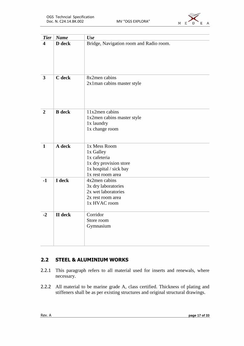
Tier Name Use
4 D deck Bridge, Navigation room and Radio room.
3 C deck 8x2men cabins
2x1man cabins master style
2 B deck 11x2men cabins
1x2men cabins master style
1x laundry
1x change room
1 A deck 1x Mess Room
1x Galley
1x cafeteria
1x dry provision store
1x hospital / sick bay
1x rest room area
-1 I deck 4x2men cabins
3x dry laboratories
2x wet laboratories
2x rest room area
1x HVAC room
-2 II deck Corridor
Store room
Gymnasium
2.2 STEEL & ALUMINIUM WORKS
2.2.1 This paragraph refers to all material used for inserts and renewals, where
necessary.
2.2.2 All material to be marine grade A, class certified. Thickness of plating and
stiffeners shall be as per existing structures and original structural drawings.

OGS Techncial Specification Doc. N. C24.14.BK.002 MV “OGS EXPLORA”
Rev. A page 18 of 33
2.2.3 All welding to be in accordance with the requirements of Classification society.
Intermittent welding can only be applied for ordinary stiffeners, subject to class
approval.
2.2.4 All stiffeners, girders, flanges, openings shall be with rounded corners to
improve the paint protection.
2.2.5 The drawings, hereby provided, do not include details of balcony, handrails,
external and internal ladders, catwalks, which shall be fabricated by the Builder
according to their best practice and standard subject to reflect the arrangement
of the proposed layout and subject to Class approval.
2.2.6 All open deck and balcony shall be protected with handrails as required by the
ILLC (International Load Line Convention) and by Class.
2.2.7 The plating throughout is to be fair, smooth and tightly fitted, and without
excessive buckles, depressions or uneven edges. All fittings, piping, etc are to
be properly and securely fastened in place.
2.2.8 NDT testing may be required by Class to test proper execution of steel works.
All structural interfaces with actual ship structures (e.g. pillar feet) shall be
tested as per Class requirements.
2.2.9 Special attention to be given to penetrations on aluminium decks and bulkheads
by steel pipe.
2.2.10 The existing radio room, actually enclosed by steel bulkheads, to be arranged
in order to accommodate a 2xmen cabin as per GA plan. The steel works and
strengthening of the necessary opening to be according Class requirements.
2.2.11 In general, all openings in existing steel structures, needed to meet the GA plan,
shall be done with the necessary strengthening curling, stiffeners, flanges etc,
in order to restore the function and in compliance with Class requirements.
2.2.12 All technical access (e.g. for installation of sanitary block) to be restored as per
Class requirements. The position of technical openings shall be to have the
minimum impact on the existing structures, as far as practicable.
2.2.13 Galley to be fitted with two fire type approved rolling shutters, one serving the
self service area in mess room and one for cafeteria, the latter existing
dimension to be reduced to min 600mm;
2.2.14 Trunks for stairways and goods lift to be A class fire insulated according to the
Fire Definition Plan; all doors in conjunction with the trunks to be same fire
class of the trunks.
2.2.15 A vertical trunk for cabling and ducting purposes to be provided between fr 57
and 58 throughout all accommodation spaces;

OGS Techncial Specification Doc. N. C24.14.BK.002 MV “OGS EXPLORA”
Rev. A page 19 of 33
2.2.16 Three watertight sliding doors, type approved, to be installed according to
drawing C24.14.H.005. All power and electrical installation to be according
SOLAS;
2.2.17 New steel means of escape (emergency exits) to be installed according to
drawing no. C24.14.H.004.
2.2.18 All windows in accommodation spaces to be moved according to GA, existing
holes to be fairly inserted (Alumium or Steel, according to the location).
2.2.19 New weather-tight door, type approved, to be installed on main deck i.w.o.
mess room, starboard side.
2.2.20 Cables shall be effectively supported and secured without damaging their outer
coverings. Space for future additional cables to be provided in major cable runs
(Approx. 15%).
2.2.21 Cable groups shall be supported on metal hangers placed clear off steel hull
structure to permit painting on surrounding structures.
2.2.22 Cable hangers shall be made of steel with corrosion resistant finish.
2.2.23 In accommodation where panel work is done over hull structure, cables shall
be concealed as far as practicable. Panel work in accommodation covering
cable runs, shall be easy dismountable.
2.2.24 The vessel is already fitted with Sewage Treatment Unit suitable for 50pax in
the store on 2nd Lower Deck SB. Such store to be split in two parts: new
transversal steel bulkhead with fire insulation of category A0 shall be placed
on frame 61 SB according to G.A. plan; new door type A0 to access to Sewage
room; the length of the corridor on 2nd Lower Deck shall be less than 7mt. In
this regard a new steel bulkhead of category A0 shall be placed at frame 60 SB.
2.3 PAINT WORKS
2.3.1 This paragraph refers to all and renewals, where necessary.
2.3.2 All structural elements shall be painted with 1x125µm epoxy paint.
Additionally the external plating will be coated with finishing paint according
with the provided by the Owners .
2.4 INSULATION WORKS
2.4.1 All material in this paragraph are intended to be supplied and installed by the
Builder. All heat, sound and fire insulation shall comply with SOLAS and
Classification Society requirements.

OGS Techncial Specification Doc. N. C24.14.BK.002 MV “OGS EXPLORA”
Rev. A page 20 of 33
2.4.2 On the basis of the specification provided herewith and by its attachments, the
Builder shall develop his own interior design drawings to the extend required
to evaluate and to perform the works. All these drawings shall be submitted to
the Owners for approval.
2.4.3 The walls and decks have to be protected by fire insulation as per Fire
Definition Plan provided by the Owners.
2.4.4 All insulation shall be covered by foil, lining or similar to avoid mineral fibers
to spread into accommodation.
2.4.5 All the deck and bulkhead penetrations necessary for the installation of piping
and electrical system to be made of SOLAS approved material and with the
same fire class of the deck/bulkheads.
2.4.6 Colours of panels, flooring, ceiling, furniture, upholsteries to be agreed with
Owners representative. In particular existing mess room shall be renewed by
keeping as unaltered as possible the original wood-style appearance.
Thermal Insulation
2.4.7 All exposed steel vertical bulkheads, and exposed horizontal deck (i.e. roof and
lower side of deck A) shall be insulated on the inside with 60mm of 45kg/m3
insulation material and retained behind the linings.
2.4.8 All piping and ducting shall be insulated to prevent any condensation and
thermal exchange with surroundings (all hot water and air conditioning pipes
to be insulated).
Deck Coverings
2.4.9 All the deck have to be covered with a primary deck covering, latex based, in
compliance with SOLAS Regulations. The above layers to be made of about
one (1) centimetre of cement and final covering by PVC covering carpet (e.g.
linoleum).
2.4.10 The change room, galley, toilets, laundries, wet laboratories and the sanitary
cabins shall be fitted out with an anti-slippery tiles floor made by ceramic 10 x
10 centimetres or similar. Epoxy or similar flooring can be accepted subject to
Owner approval.
Lining
2.4.11 All accommodation ceiling, partitions, boarding panels, inspection doors,
doors, etc shall comply with SOLAS Regulations and according to the Fire
Definition Plan provided by the Owners.
2.4.12 Partitions between cabins shall be made by 50mm thick panels class B15.
2.4.13 Lining on the exposed walls shall be made by 25mm thick panels class B15.

OGS Techncial Specification Doc. N. C24.14.BK.002 MV “OGS EXPLORA”
Rev. A page 21 of 33
2.4.14 Partitions between corridors and cabins, offices and corridors, offices and
offices shall be done by deck-to-deck panels class B15.
2.4.15 Colours scheme to be chosen by Owners or their appointed persons.
2.4.16 Existing transversal partition at frame 62 on the bridge to be open in order to
have a common open area on the bridge.
2.5 CABINS, LABORATORIES AND COMMON SPACES
2.5.1 All material in this paragraph are intended to be supplied and installed by the
Builder and to be in compliance with SOLAS and Classification Society
requirements and supplied with certificates.
2.5.2 All doors to have labels overhead indicating the compartment name, and to be
fitted with a Master-Key system for the locks. All internal doors shall be B15
type except doors in way stairway and HVAC room, which are required to be
A15 type.
2.5.3 All corridors to be fitted with handrails on one side, power sockets 220V/60Hz
located every 4 m on one side and a ceiling built-in lamp (neon lamp 2x18/33W
each) located every 4m.
2.5.4 Furniture covering laminates to be made by hard plastic laminate (e.g.
Perstrop) and all corners to be rounded to avoid injuries. All the furniture shall
be fitted in order to avoid any dead space and to permit easy cleaning and made
by plywood with marine standard outfittings.
2.5.5 All cabins will be fitted with single tier built-in double bed (i.e. bunk bed)
except the cabin designated to accommodate Master and Chief Engineer.
2.5.6 All cabins will be fitted with a sanitary block except for the four cabins on the
first lower deck.
2.5.7 Existing hospital to be converted in a sick bay and a dry provision store.
2.5.8 Existing dry provision store to be converted in gymnasium.
2.5.9 Existing store on 2nd lower deck between fr 55 and 68 to be split in two parts,
fore part of the store to be fitted with a handling room as shown on GA-plan.
2.5.10 Existing radio room with all equipment and cabling to be moved on the bridge.
2.5.11 Stairs within staircase to be complete with handrail, to be made according to
the good practice to be supplied and fitted out by the Yard.

OGS Techncial Specification Doc. N. C24.14.BK.002 MV “OGS EXPLORA”
Rev. A page 22 of 33
2.5.12 Additional vertical emergency exits to be fitted as per drawing n. C24.14.H.004
Cabins
2.5.13 There are twentysix (23) cabins, each one to accommodate 2 persons. There
are three cabin, master style, fitted with day room and restroom, able to
accommodate 2 persons. Each cabin has an attached independent sanitary
cabin. Reference to be made to the GA.
2.5.14 All materials to be type approved and provided with MED certificate, as
applicable.
2.5.15 Furniture in cabins to be according to the Piano Alloggi (Italian Language) n.
C24.14.BK.004. Design, colours and arrangement of furiniture to be subject to
Owner approval.
Laboratories
2.5.16 Furniture in laboratory to be according to the GA plan.
2.5.17 Design, colours and arrangement of furiniture to be subject to Owner approval
2.5.18 Wet laboratories to be fitted with tables, in laminated, and wash bowls, Tables
height to be 900mm and to be fitted with lashing devices for fatening of
equipment and computers on top.
2.5.19 Each wet laboratory to be fitted with a vacuum hood with dedicated and
independent exhast fan and ventilation flat above freeboard deck.
2.5.20 Doors leading to laboratories shall have free width of min 1000mm.
2.5.21 Portside corridor on laboratory deck to be fitted with sliding watertight door
leading to cargo hold and with vertical emergency exit 900x900mm minimum
dimensions.
Galley
2.5.22 Final layout of the galley shall reflect actual arrangement.
2.5.23 Existing galley and cafeteria equipment to be dismantled and stored by Builder.
After completion of modernization works all equipment to be restored back.
2.5.24 Galley to be fitted with an anti-slippery tiles floor made by ceramic 10 x 10
centimetres or similar.
2.5.25 Existing drain to be preserved.
Mess Room

OGS Techncial Specification Doc. N. C24.14.BK.002 MV “OGS EXPLORA”
Rev. A page 23 of 33
2.5.26 Mess room shall be renewed by keeping as unaltered as possible the original
wood-style appearance.
2.5.27 Additionally, a weather tight door to be installed on portside as shown in GA
plan.
Bridge
2.5.28 Existing transversal partition at frame 62 on the bridge to be open in order to
have a common open area on the bridge.
Sick Bay
2.5.29 Existing hospital to be converted in a sick bay and a dry provision store;
Other spaces
2.5.30 As for arrangement of other accommodation spaces, GA to be used as
reference.
2.6 EXTERNAL FITTINGS
Windows
2.6.1 All the cabins and common spaces to be fitted out with windows typical
dimension 400x560mm, as per GA, type movable complete with stopper and
in compliance with SOLAS Regulations.
2.6.2 Each window shall be provided with suitable window box made by non-ferrous
material.
2.6.3 Each cabin window to be provided with darkening curtains.
External Doors
2.6.4 All external doors to be replaced by new doors made of PVC or equivalent
material, easy open type, with glass according to Solas regulations and Class
requirements.
2.7 ELECTRICAL SYSTEM
OGS Techncial Specification Doc. N. C24.14.BK.002 MV “OGS EXPLORA”
Rev. A page 24 of 33
2.7.1 All the materials mentioned within this paragraph to be supplied, provided with
MED certificate, as applicable, and installed by Builder .
2.7.2 All the accommodation spaces to be provided with power supply 200V/50Hz
provided by the Ship main of the vessel. Wirings, penetrations and distribution
boards to be in compliance with SOLAS and Class requirements.
2.7.3 Each cabin to be connected to a sub-switchboard, located on each floor, by
dedicated breaker.
2.7.4 Builder shall provide all necessary cabling for the implementation of a Pubblic
Address (PA) in each corridor and common spaces.
2.7.5 Builder shall provide all necessary cabling for the implementation all fire
detection sensors as per attached drawing in each corridor and common spaces.
2.7.6 Sensors and fire control unit shall be supplied and installed by Builder.
2.7.7 Wiring design to be done by Builder .
2.7.8 Each cabin to be fitted as follows:
a) Two (2) ceiling built-in lamps (neon lamp 2x18/33W each)
b) One (1) celing-mounted air diffuser unit
c) One (1) internal telephone plug located on top of the desk
d) Two (2) LAN/Ethernet plug located on top of the desk
e) Two (2) spare power points 220V/60Hz located on top of the desk
f) Two (2) power points 220V/60Hz – 15 A located every 2 meters around
the perimeter
2.7.9 Each laboratory to be fitted as follows:
a) A certain number, according to existing arrangement, of ceiling built-
in lamps (neon lamp 2x18/33W each)
b) A certain number, according to existing arrangement, celing-mounted
air diffuser unit
c) One (1) internal telephone plug located on top of the desk
d) Four (4) LAN/Ethernet plug located on top of the desk
e) Two (2) spare power points 220V/60Hz located on top of the desk
f) Two (2) power points 220V/60Hz – 15 A located every 2 meters around
the perimeter
2.7.10 Existing UPS for scientific consumers to be kept in place, while batteries to be
replaced. Provision and installation of battery-pack to be done by Builder.
2.7.11 Each corridor, stairway, store, change room and mess room to be fitted as
follows:

OGS Techncial Specification Doc. N. C24.14.BK.002 MV “OGS EXPLORA”
Rev. A page 25 of 33
g) A certain number, according to existing arrangement, of ceiling built-
in lamps (neon lamp 2x18/33W each)
h) Two (2) power points 220V/60Hz – 15 A located every 2 meters around
the perimeter
2.8 PIPING SYSTEMS
2.8.1 All the materials mentioned in this paragraph to be designed, supplied and
installed by Builder in compliance with Rina requirements.
2.8.2 All the piping mentioned in this paragraph is intended to be deep galvanized.
Black water system
2.8.3 All the pipe to be not less than 5° sloped down against the upright water plane.
2.8.4 Penetrations to be in compliance with Class Requirements.
2.8.5 Reference to be made to the attached drawings.
Grey water system
2.8.6 All the pipe to be not less than 7° sloped down against the upright water plane.
2.8.7 Penetrations to be in compliance with Class Requirements.
2.8.8 Reference to be made to the attached drawings.
2.8.9 All the black and grey water pipes shall be led to a sewage treatment unit,
already fitted on board the vessel, and to be installed by Builder below the
lowest accommodation tier.
Hot and Cold water system
2.8.10 Cold and hot water supply points to be provided as needed for:
a) each sanitary cabin
b) dirty mess room
c) day room
2.8.11 The hot water line to be thermally insulated, arranged with recirculation piping,
and connected with the existing system of the vessel.
2.8.12 Penetrations to according to Class Requirements.
2.8.13 Piping drawings to be produced by ShipBuilder and supplied to the vessel.

OGS Techncial Specification Doc. N. C24.14.BK.002 MV “OGS EXPLORA”
Rev. A page 26 of 33
2.9 HVAC system
2.9.1 An Hot Ventilation and Air Conditioning system to be install in replacement
of the existing system located in the dedicated room on deck I, between frame
38 and 45.
2.9.2 System and Piping design shall be made by the Builder.
2.9.3 The external reference condition for the AC system to be assumed with 35°C
and 80% umidity and sea water 36°C.
2.9.4 The AC system to assure the following conditions:
a) in cabins temperature not higher than 25 °C, with humidity in the range
40-60%,
b) in offices and working spaces not higher than a 25 °C, with humidity in
the range 40-60%,
c) noise and vibration to be minimized according to ILO Regulations.
2.9.5 The external reference condition for the hot ventilation system to be assumed
-10°C.
2.9.6 The hot ventilation system to assure the following conditions:
d) in cabins temperature not lower than 20°C,
a) in offices and working spaces not higher than a 20 °C.
2.9.7 Ducts drawings to be produced by the Builder and supplied to the vessel.
2.9.8 AC ducting to be insulated to avoid condensation.
2.9.9 Capacity to be based on max. re-circulated air amount of 50%. Arrangement to
ensure easy damper settings for approx. 30-100% fresh air supply. No re-
circulated air from toilets, wash rooms and mess rooms.
2.9.10 HVAC unit shall be complete built onto one common baseframe together with
two separated system by 50% of total power each, compressors with capacity
control and seawater-resistant condensators
2.9.11 Supply air flow to be individually controlled in each room and outlets to be
through doors to adhering alleyway, and exhaust through ceiling mounted
exhaust registers in sanitary blocks.
2.9.12 The plant to be arranged for automatic capacity control.

OGS Techncial Specification Doc. N. C24.14.BK.002 MV “OGS EXPLORA”
Rev. A page 27 of 33
2.9.13 The air conditioning unit, marine type, shall be equipped with Electrical Heater
for Heating Air function.
2.9.14 The unit will be fitted with fresh air intake with water mister catcher to ensure
that smoke from funnel and air from accommodation exhaust and crankcase
outlets is not flowed into A/C unit.
2.9.15 The Air Ventilation units, cabin units, dampers, compressors,
condensers/receivers and all the fittings of the plant will be supplied and
installed by the Builder.
2.9.16 In accordance with the manufacturer’s recommendations, the Builder will take
particular care of directing ducting, insulation of ducting through bulkheads,
proper location of outlets and louvers and number of design of louvers.
Exhaust Ventilation
2.9.17 An exhaust ventilation system to be designed and installed by the Builder to
extract vapours from all the toilets and, with separated ductiong, air from
laboratories, mess room, change room, laundries and gym.
2.9.18 A ventilation fan shall be fitted in the externally, one per each deck, and so that
to blow exhaust air outside through a steel ventilation flap.
2.10 LIFE SAVING APPLIANCES & FIRE FIGHTING EQUIPMENT
2.10.1 All LSA and FiFi equipment shall be supplied by Owners.

OGS Techncial Specification Doc. N. C24.14.BK.002 MV “OGS EXPLORA”
Rev. A page 28 of 33
3 MAIN GROUP B – ENGINE ROOM & OTHER MACHINERY SPACES
3.1 OVERVIEW
3.1.1 All insulation material in engine room and engine control room, including
doors, are to be dismantled and scrapped.
3.1.2 New insulation to be installed according to Fire Definition Plan and complying
with SOLAS and Classification Society requirements.
3.2 STEEL WORKS
3.2.1 Existing door at fr 25 to be made gas-tight.
3.2.2 Additional sliding watertight doors to be fitted as per drawing n. C24.14.H.005.
3.2.3 Existing vertical trunkig for emergency exit at fr.11-12 to be modified by
blanking access from “sala streamer” (aft access).
3.2.4 Additional vertical emergency exits to be fitted as per drawing n.
C24.14.H.004.
3.3 INSULATION WORKS
3.3.1 All insulation material in engine room and engine control room, including
doors, are to be dismantled and scrapped.
3.3.2 New insulation to be installed according to Fire Definition Plan and complying
with SOLAS and Classification Society requirements.
3.4 PIPE WORKS
3.4.1 Actual pipeline for bildge system to be extended forward up to the fore cargo
hold and fitted with all necessary fitting as per drawing n. C24.14.P.001.

OGS Techncial Specification Doc. N. C24.14.BK.002 MV “OGS EXPLORA”
Rev. A page 29 of 33
4 MAIN GROUP C – HULL
4.1 CARGO HOLD
4.1.1 Cargo hold to be split in two parts by means of installation on a new watertight
steel bulkhead as indicated in GA and drawing n. C24.14.H.003.
4.1.2 The bulkhead to be arranged in cargo holds at the frame #82-#81 extending
from tank top to main deck (a watertight floor already exists at frame #82).
4.1.3 The bulkhead shall be stiffened on the aft side.
4.1.4 The new transverse watertight bulkhead subdivide the cargo hold area in:
a) Forward high cargo hold;
b) Aftward high cargo hold;
c) Forward low cargo hold;
d) Aftward low cargo hold.
4.1.5 Forward cargo hold to be provided by two new bilge wells (drawing n.
C24.14.H.006) with all necessary fittings (strainers, high-level alarms, etc.)
and valves to be connected to the existing bilge system. Alarms repeated in
ECR and on the bridge.
4.1.6 Shortening of the existing hatch opening and coamings according to drawing
C24.14.H.002 and in order to stow one ISO 20 container.
4.1.7 Provision and installation of a new hatch cover, approx. dimension
6500x400mm, lift-away type approved, consisting in at least two panels. The
cover to be suitable to support one ISO20 container and fitted with suitable
securing arrangements.
4.1.8 Steel insert on main deck and 1st lower deck to restore deck continuity after
shortening of hatch opening.
4.1.9 All new parts of decks to have the same sheer and camber of the relevant
adjacent exiting deck.
4.1.10 Modification of the movable patch with size approx. 5580 x 4000 mm in cargo
hold on first lower deck according to C24.14.H.002.
4.2 STABILITY
4.2.1 Installation of fixed ballast weights in double bottoms for an aggregate weight
of 34000 kg at x=33.00m, y=0.00, z=0.3m above base line.

OGS Techncial Specification Doc. N. C24.14.BK.002 MV “OGS EXPLORA”
Rev. A page 30 of 33
4.2.2 When the ship is as near fulfilment as possible, an inclination experiment to be
carried out and stability calculations to be submitted to the Class for approval.
4.3 OPEN DECKS – WORK AREA
4.3.1 Sea fastening devices, twist lock type, to be installed on forward weather deck
in order to carry 1 off ISO20 container on hatch covers and 1 off ISO10
Containers on deck between frames 72 and 80, starboard side.
4.3.2 A platform made of steel suitable steel profiles and twist lock to be installed as
extension of deck B (ponte cabine) in order to fit 1 off ISO20 and 1 off ISO10
Containers.
4.3.3 New platforms on aft open deck to be installed, on portside and starboard side,
to extend transversally the working area; new structures will be fabricated and
installed by the builder as shown in drawing no. C24.14.H.007.
Emergency Exits
4.3.4 Four new emergency exit shall be provided through the vessel and are to be
arranged at the following positions:
a) Emergency hatch between frame #0 - #1 on A-Deck PS, dimens.
600x600mm;
b) Emergency hatch between frame #35 - #36 on A-Deck PS, dimens.
600x600mm;
c) Emergency hatch between frame #73 - #74 on A-Deck SB, dimens.
900x900mm;
d) Emergency exit door at frame #65 on A-Deck SB in Mess Room
4.3.5 Hatches from open deck to be of watertight type with steel coamings and steel
covers. All emergency hatches/door to be arranged with approved closing
appliances. Height of coaming to be 600 mm.
4.3.6 All trunks of new emergency exits to be in accordance with classification
society requirements.
4.3.7 The existing door at frame #11 on I-Deck, giving access to the emergency trunk
shall be inserted. The existing emergency trunk is intended only for E.R.
escape.

OGS Techncial Specification Doc. N. C24.14.BK.002 MV “OGS EXPLORA”
Rev. A page 31 of 33
5 MAIN GROUP D – CARGO AND EQUIPMENT HANDLING SYSTEMS
5.1 ROSETTE A-FRAME
5.1.1 An CTD LARS, A-frame type, suitable for launching and recovery of the
rosette water sampling carousel, type SBE 32 to be provided installed and
commissioned by the Builder.
5.1.2 The A-frame shall work on local and remote control system.
5.1.3 Location of the A-frame is approximatively at fr. 73-79 on stardboard side,
main deck.
5.1.4 Bulwarks to be open, and suitable crew protection systems (handrails, chains,
etc.) to be fitted in way of the opening.
5.1.5 The A-frame and its pistons to be installed on its own skid, which is to be
provided with suitable fastening flanges or feet.
5.1.6 A winch, fitted with electrical slip-ring, suitable to carry 6000m steel wire with
diameter of 11.4mm to be provided, installed and commissioned by the Builder
including hydraulic power unit.
5.1.7 All power and electrical connection to be done by the Builder.
5.2 CARGO CRANE
5.2.1 The existing derrick crane to be replace by a conventional marine crane with
capacity of 50tons x meter, able to 15m maximum outreach.
5.2.2 The existing derrick mast to be removed.
5.2.3 The existing exhaust gas piping for diesel generator and the existing ventilation
opening for cargo hold, actually supported by the derrick-mast, to be re-routed
on portside and enclosed within a dedicated funnel-ventilation duct, erected
and built according to Class and ILLC requirements.
5.2.4 A fore mast to be fitted to carry the statutory lights and signals, actually
installed on derrick mast.

OGS Techncial Specification Doc. N. C24.14.BK.002 MV “OGS EXPLORA”
Rev. A page 32 of 33
5.3 AFT A-FRAME
5.3.1 Modification of the existing A-frame SWL 20tons, by lengthening of the legs
up to 7000mm and replacement of the upper transverse to reach overall beam
of 11000, SWL to be de-rated accordingly.

OGS Techncial Specification Doc. N. C24.14.BK.002 MV “OGS EXPLORA”
Rev. A page 33 of 33
6 MAIN GROUP E – ELECTRICAL & MACHINERY SYSTEMS
6.1 STATUTORY REQUIREMENTS
6.1.1 This paragraph refers to the electrical installations, other than the ones related
to the accommodation domestic purposes, needed to comply with SOLAS
74/83.
6.1.2 Installation of alarm for low pressure for starting air on bridge (in compliance
with reg.31.2.9 cap. II-1).
6.1.3 Relocation of the emergency fire pump from the actual position to the forward
cargo hold, 1st lower deck, portside, at frame 95 (in compliance with reg.39
cap. II-1).
6.1.4 The alarm system for ER to be continuously powered by and provided with
auto-change-over to a stand-by power supply (e.g. battery backup) (in
compliance with reg.51.1.2 cap. II-1), actually such arrangement is available
only for DDGG.
6.1.5 Existing goods lift at frame 55-57, electrical and mechanical parts to be
refurbished, doors at each level to be replaced with fire approved type door as
shown in the drawing Fire Definition Plan (n. C24.14.S.001).
6.1.6 A 6 sockets panel, fitted with 3x32A 380V sockets IP67 and 3c16A 380V IP67
sockets to be fitted by the Builder at the following locations:
e) on main deck, stardboard and portside side, at approx. fr. 68,
f) on deck B, center, at fr 32,
g) in forward cargo hold, on deck I, portside, at fr 82,,
h) in aft cargo hold, on deck I, portside, at fr 82
6.1.7 All necessary wiring from panels to spare breaker on main switchboard to be
installed by the Builder.
6.2 BOW THRUSTER REFURBISHMENT
6.2.1 Replacement of the starter cabinet of the bow thruster with a Frequency
Converter, suitable for the thruster and able to be remotely controlled. The
remote control system to be installed with control panel on the bridge and alarm
panel on ECR and repeated on the bridge.