Embed Size (px)
Citation preview
MVG25 Valve Gate
www.mastip.com
System Overview
MVG25-2
MVG25 Valve Gate
© Copyright Mastip Technology Limited. Information subject to alteration. V2.03 www.mastip.com
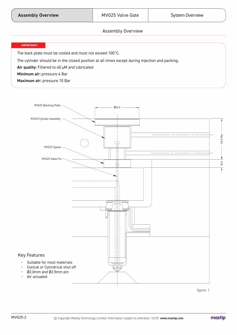
MVG25 Blanking PlateØ54.0
50.0
Min
10.0
MVG25 Cylinder Assembly
MVG25 Spacer
MVG25 Valve Pin
Assembly Overview
Key Features• Suitable for most materials• Conical or Cylindrical shut off• Ø2.0mm and Ø2.5mm pin• Air actuated
Assembly Overview
figure. 1
1.
The back plate must be cooled and must not exceed 100˚C.
The cylinder should be in the closed position at all times except during injection and packing.
Air quality: Filtered to 40 μM and lubricated
Minimum air: pressure 4 Bar
Maximum air: pressure 10 Bar
IMPORTANT!!

MVG25-3
System Overview MVG25 Valve Gate
© Copyright Mastip Technology Limited. Information subject to alteration. V2.03 www.mastip.com
44.0
62.0
55.0
62
.043
.0
30.0 30.0
60.0 60.0
Cooling Cooling CoolingAirwaysAirways
Standard
With modified blanking plate
Spacing Layout
figure. 2
Spacing Layout

System Overview
MVG25-4
MVG25 Valve Gate
© Copyright Mastip Technology Limited. Information subject to alteration. V2.03 www.mastip.com
Ø53.8
35.0
at c
lose
d po
sitio
n
58.5
ØD
L
Nozzle Compatibility
Description Nozzle Tip Nozzle Length Supplied Pin Size
MVG25-P1 Headed Pin
MX13 OV 45 - 175 Ø2.0
BX13 OV 45 - 225 Ø2.0
MX16 OV / TV 45 - 175 Ø2.5
BX16 OV / TV 45 - 250 Ø2.5
MVG25 Overall Dimensions
figure. 3
Note: Pins are supplied in standard length and must be cut to required length before installation.
Pins can be supplied finished ready to use by Mastip
Refer to page MVG25-6 Pin Calculations section to calculate required final pin lengths
Overall Dimensions
MVG25-5
System Overview MVG25 Valve Gate
© Copyright Mastip Technology Limited. Information subject to alteration. V2.03 www.mastip.com
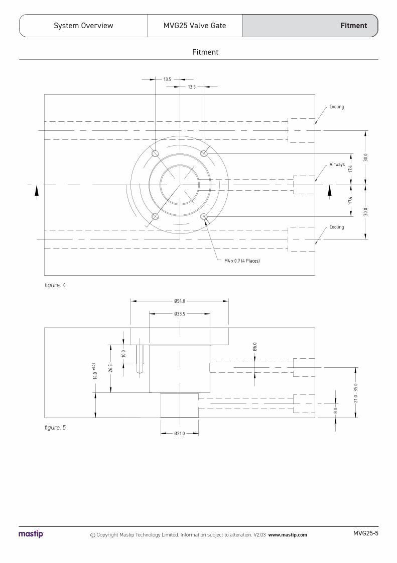
Fitment
M4 x 0.7 (4 Places)
Cooling
13.513.5
17.4
17.4
30.0
30.0
8.0
21.0
- 35
.0
26.5
10.0 Ø6
.0
Ø21.0
Ø33.5
Ø54.0
Airways
Cooling
14.0
±0.0
2
figure. 5
Fitment
figure. 4
System Overview
MVG25-6
MVG25 Valve Gate
© Copyright Mastip Technology Limited. Information subject to alteration. V2.03 www.mastip.com
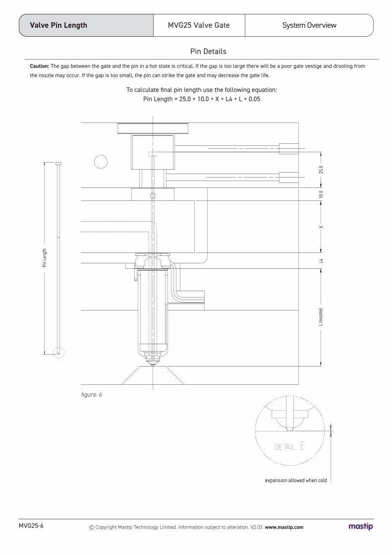
Pin Details
To calculate final pin length use the following equation:Pin Length = 25.0 + 10.0 + X + L4 + L + 0.05
Caution: The gap between the gate and the pin in a hot state is critical. If the gap is too large there will be a poor gate vestige and drooling from
the nozzle may occur. If the gap is too small, the pin can strike the gate and may decrease the gate life.
Valve Pin Length
L (n
ozzl
e)L4
X
Pin
Leng
th
1022
expansion allowed when cold
L (n
ozzl
e)L4
X10
.025
.0
Pin
Leng
th
figure. 6

MVG25-7
System Overview MVG25 Valve Gate
© Copyright Mastip Technology Limited. Information subject to alteration. V2.03 www.mastip.com
Gate Configuration
d1
40.0
R0.1
R0.1
d2
D
+0-0.02
+0.0-0.5
The pin will form a 0.1mm deep dimple on the part.
Pin and gate to be lapped to ensure clean shutoff.
Recommended for amorphous polymers.
The pin will form a 0.1mm deep dimple
on the part.
Recommended for semi-crystalline
and filled polymers.
Description D d1 d2 GT qT HT
MVG25-P1 Headed Pin 2.0 1.3 1.25 1.3 0.8 1.0
MVG25-P1 Headed Pin 2.5 1.8 1.75 1.8 1.0 2.0
Conical Valve Gate Cylindrical Valve Gate
Gate Quality *** ***
Pin Cooling *** *
Filled Materials * ***
Material with Small Moulding Window * ***
Ease of Pin Setup * ***
Ease of Gate Manufacture *** **
Gate Life *** *
ØAP
BP IP
90°
±0.0025
R0.1
R0.1
R0.1
AF
D
CP
Description D AP BP AF CP GP qP HP
MVG25-P1 Headed Pin 2.0 1.292 2.0 1.6 5 1.305 0.5 1.0
MVG25-P1 Headed Pin 2.5 1.792 2.0 2.1 5 1.805 0.7 2.0
90°
ØGP
qP
HP
±0.005
Cylindrical Valve Gate
Conical Valve Gate
Conical and Cylindrical Valve Gate Recommendations
ØGT ±0.02
qT HT
90°
40°
Key Value
* Lowest Rating
*** Highest Rating

System Overview
MVG25-8
MVG25 Valve Gate
© Copyright Mastip Technology Limited. Information subject to alteration. V2.03 www.mastip.com
B MVG25 VALVE PIN + SEAL
Exploded DiagramAs Supplied
Exploded Diagram
A MVG25 CYLINDER ASSEMBLY
Valve Pin7
Piston Rod Seals
Circlip11
Cylinder End Seal
Locating Spacer
Blanking Plate Screw1
Blanking Plate2a 2b
Blanking Plate Seal3
Piston9
Valve Pin Adjustment Packers
6b6c6d
Piston Main Seal8
Pin Locking Screw4Pin Head Seal5Valve Pin Adjustment Packer
6a
Cylinder
Valve Pin Seal

MVG25-9
System Overview MVG25 Valve Gate
© Copyright Mastip Technology Limited. Information subject to alteration. V2.03 www.mastip.com
TWO
Fit the Cylinder End Seal 13 to the Cylinder 12
Apply grease* to Cylinder End Seal 13
Installation and Pin Adjustment Guide
PRE INSTALLATION
1. Verify the actuator pockets and air circuits are machined in the back plate as shown in figure 5.2. Ensure there are no sharp edges or burrs in the actuator pockets.3. Ensure the actuator pocket and air circuits are clean. 4. Cut pins to length and profile end to conical or cylindrical form (refer nozzle approval drawing)5. Assemble the fixed half of the mould including hot runner nozzles and manifold excluding backplate. Refer to the Technical Specifications section of the Technical Guide Pin and seal are a matched set and must remain paired.
INSTALLATION
ONE
THREE
Installation
Ensure all components are clean
Fit the Cylinder 12 and Locating Spacer 14 to the mould backplate and retain using the Circlip 11 Ensure Cylinder 12 is compressing Cylinder End Seal 13 to fit Circlip 11 securely in groove on Locating Spacer 14
FOUR
Apply grease* to the sealing bores of the Locating Spacer 14 and Cylinder 12 and to the pre fitted Piston Seals 8 & 10 Fit Piston 9 to the Cylinder 12
* Mastip recommends using high temperature silicon grease

System Overview
MVG25-10
MVG25 Valve Gate
© Copyright Mastip Technology Limited. Information subject to alteration. V2.03 www.mastip.com
SIX
INSTALLATION CONT.....
Installation
Centralise Cylinder Assembly A to the Actuator pocket.
Clean any residual material from the pin seal pocket and thread in the manifold.
Apply heat resistant nickel based anti-seize to the thread of the new pin seal and screw into the manifold and tighten to 20Nm.
Ensure pins slide smoothly through the pin seal after tightening.
FIVE
equal equal

MVG25-11
System Overview MVG25 Valve Gate
© Copyright Mastip Technology Limited. Information subject to alteration. V2.03 www.mastip.com
SEVEN
Installation
Fit mould backplate to mould and fasten.
Note: If backplate location guides start to locate first, then the cylinder assembly should self locate to the manifold. However in some cases it may be necessary to move the cylinder assemblies in the actuator pocket to locate them with the manifold.
INSTALLATION CONT.....

System Overview
MVG25-12
MVG25 Valve Gate
© Copyright Mastip Technology Limited. Information subject to alteration. V2.03 www.mastip.com
Installation
INSTALLATION CONT.....
NINE
Fit Blanking Plate Seal 3 to Blanking Plate 2a or 2b
Insert the Valve Pin Adjustment Packers 6b , 6c & 6d onto the Valve Pin 7Ensure the correct packer thickness is in the correct position. (Recommend starting with the thinnest packer above the pin head, then adjust to suit if necessary).Fit the Valve Pin 7 to Piston 9Fit the remaining Valve Pin Adjustment Packer 6a above the pin head Fit the Pin Head Seal 5 to the Piston 9 Fit the Pin Locking Screw 4 to the Piston 9 and tighten to 40Nm
EIGHT
2.25
2.35
2.45
2.55
MVG25-13
System Overview MVG25 Valve Gate
© Copyright Mastip Technology Limited. Information subject to alteration. V2.03 www.mastip.com
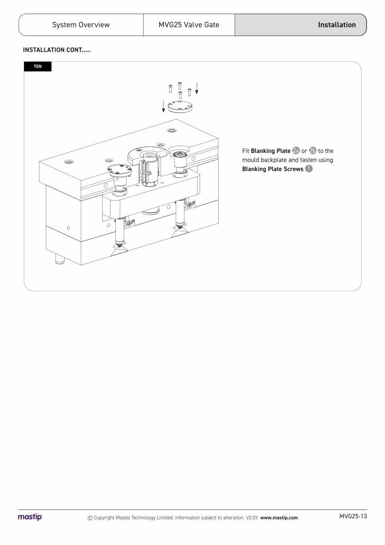
Installation
Fit Blanking Plate 2a or 2b to the mould backplate and fasten using Blanking Plate Screws 1
TEN
INSTALLATION CONT.....

System Overview
MVG25-14
MVG25 Valve Gate
© Copyright Mastip Technology Limited. Information subject to alteration. V2.03 www.mastip.com
Pin Height Adjustment
ONE
Remove Blanking Plate 2a or 2b
PIN HEIGHT ADJUSTMENT
MVG25-15
System Overview MVG25 Valve Gate
© Copyright Mastip Technology Limited. Information subject to alteration. V2.03 www.mastip.com
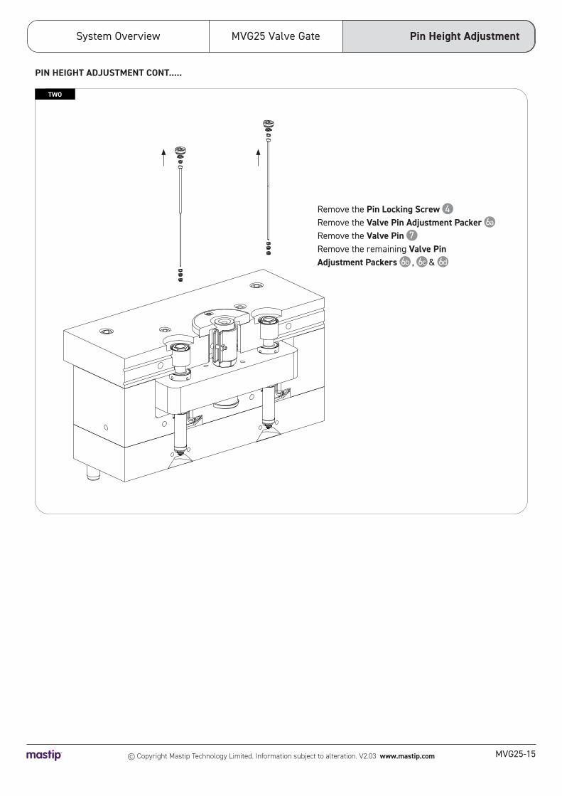
TWO
Remove the Pin Locking Screw 4 Remove the Valve Pin Adjustment Packer 6a
Remove the Valve Pin 7 Remove the remaining Valve Pin Adjustment Packers 6b , 6c & 6d
Pin Height Adjustment
PIN HEIGHT ADJUSTMENT CONT.....

System Overview
MVG25-16
MVG25 Valve Gate
© Copyright Mastip Technology Limited. Information subject to alteration. V2.03 www.mastip.com
Pin Height Adjustment
THREE
FOUR
Swap Valve Pin Adjustment Packers 6a , 6b , 6c & 6d to achieve small pin adjustments (different packer = different height)
Move one or more Valve Pin Adjustment Packers 6a , 6b , 6c & 6d from below the pin head to above the pin head to achieve large pin adjustment
PIN HEIGHT ADJUSTMENT CONT.....
Minor Adjustment
Major Adjustment
+0.1
2.25
2.35
2.45
2.55
+0.2
+0.3
+2.35
2.25
2.35
2.45
2.55
MVG25-17
System Overview MVG25 Valve Gate
© Copyright Mastip Technology Limited. Information subject to alteration. V2.03 www.mastip.com
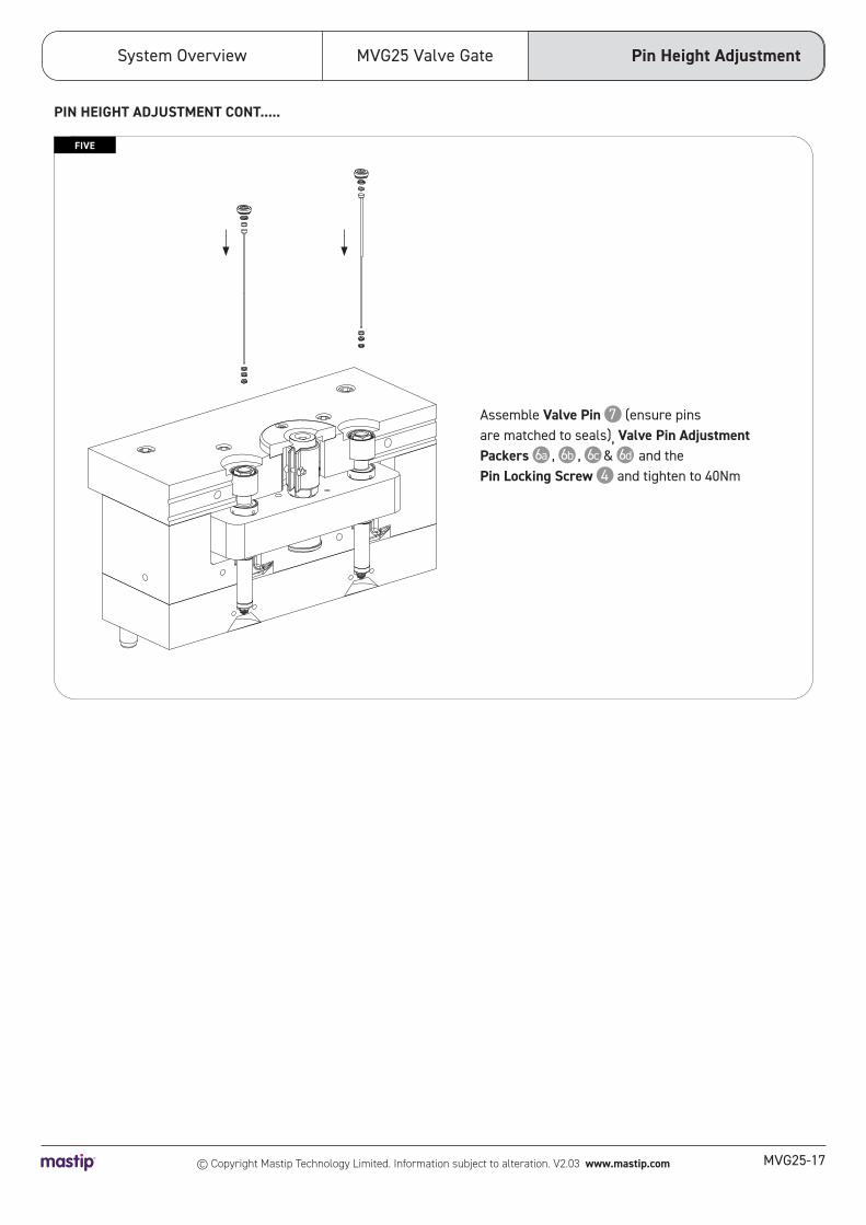
FIVE
Assemble Valve Pin 7 (ensure pins are matched to seals), Valve Pin Adjustment Packers 6a , 6b , 6c & 6d and the Pin Locking Screw 4 and tighten to 40Nm
Pin Height Adjustment
PIN HEIGHT ADJUSTMENT CONT.....

System Overview
MVG25-18
MVG25 Valve Gate
© Copyright Mastip Technology Limited. Information subject to alteration. V2.03 www.mastip.com
Pin Height Adjustment
SIX
Fit Blanking Plate 2a or 2b to the mould backplate and fasten using Blanking Plate Screws 1
PIN HEIGHT ADJUSTMENT CONT.....

MVG25-19
System Overview MVG25 Valve Gate
© Copyright Mastip Technology Limited. Information subject to alteration. V2.03 www.mastip.com

© Copyright Mastip Technology Limited. Information subject to alteration. 40-000-070 V2.03
Mastip Head Office New Zealand
Physical Address 558 Rosebank Road, Avondale Auckland 1026, New Zealand
Postal Address PO Box 90651, Victoria St West Auckland 1142, New Zealand
Phone: +64 9 970 2100 Email: [email protected]
Mastip Regional Office Europe Phone: +33 0 809 400 076 Email: [email protected]
Mastip Regional Office North America Phone: +1 262 644 9400 Email: [email protected]
Mastip Regional Office China Email: [email protected]
For a full list of Distributors, please visit www.mastip.com