Embed Size (px)
Citation preview

In cadrul activității “1. Efectul US si MW asupra reacțiilor enzimatice, dezvoltarii celulelor şi formării
catalizatorilor” , subactivitățile “1.1.Studii referitoare la efectul US şi MW asupra reacţiilor enzimatice şi a celulelor
vii” și „1.2.Sinteza nanocatalizatorilor şi utilizarea lor în reacţii asistate de US şi MW” , seminarul de lucru:
“Intensificarea proceselor prin utilizarea combinata US si
MW: teorie si experiment”.
Ioan Calinescu
08.06.2017
Proiect cofinanţat din Fondul European de Dezvoltare Regională prin Programul Operaţional Competitivitate 2014-2020
Axa prioritară 1 Cercetare, dezvoltare tehnologică și inovare (CDI) în sprijinul competitivităţii economice și dezvoltării afacerilor
Acţiunea 1.1.4. Atragerea de personal cu competențe avansate din străinătate pentru consolidarea capacității de CD
Titlul proiectului: “Tehnici neconvenționale cu Ultrasunete/Microunde utilizate pentru activarea proceselor chimice şi nonchimice ”
Număr de înregistrare electronică: P_37_471
Nr contract: 47/05.09.2016
Beneficiar: Universitatea POLITEHNICA din Bucureşti
Content
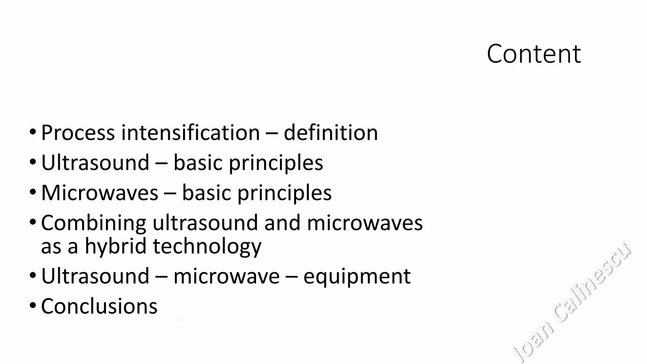
• Process intensification – definition • Ultrasound – basic principles • Microwaves – basic principles • Combining ultrasound and microwaves
as a hybrid technology • Ultrasound – microwave – equipment • Conclusions

Process intensification - definition • In 1995, while opening the 1st International Conference on Process
Intensification in the Chemical Industry, Ramshaw, one of the pioneers in the field, defined process intensification as a strategy for making dramatic reductions in the size of a chemical plant so as to reach a given production objective (Stankiewicz and Mouljin 2000).
• Process intensification consists of the development of novel apparatuses and techniques that, compared to those commonly used today, are expected to bring dramatic improvements in manufacturing and processing, substantially decreasing equipment-size/production-capacity ratio, energy consumption, or waste production, and ultimately resulting in cheaper, sustainable technologies (Stankiewicz and Mouljin 2000).
• Or, to put this in a shorter form: any chemical engineering development that leads to a substantially smaller, cleaner, and more energy efficient technology is process intensification!

Fig. 1 Process intensification and its components.(Stankiewicz and Mouljin 2000)

Fig. 2 One vision of how a future plant employing process intensification may look (right) vs. a conventional plant (left) [Meili, A., “Practical Process Intensification Shown with the Example of a Hydrogen Peroxide Distillation System,” Proceedings, 2nd Intl. Conf. Proc. Intensif. in Pract., BHR Group, London, 28, pp. 309–318 (1997)..

Ultrasound – basic principles
We normally associate sound with communication and music but seldom think of it as an energy source. It is therefore something of a surprise to find that sound can be used to sterilize water, improve electroplating, produce better face creams, treat cancer and much more (Leonelli and Mason 2010).
These remarkable effects come from the energy released by cavitation bubbles generated in a liquid by sound waves.
Sonochemistry is based upon harnessing the energy of such bubbles to create changes in a medium and is generally associated with the use of ultrasonic sound frequencies.

Power ultrasound which is capable of influencing chemistry and processing and is mainly in the frequency range between 20 and 100 kHz.
Diagnostic ultrasound which does not have enough power to produce cavitation, is at very high frequencies (above 5 MHz) and is used in for example in foetal scanning.

The potential of using acoustic cavitation to create changes in materials was identified in the USA in the late 1920s. Over the succeeding years after a great deal of pioneering work in sonochemistry, two reviews on the applications of ultrasound in polymer and chemical processing were published in the 1940s • H. Mark, Some applications of ultrasonics in high-polymer research, J.
Acoust. Soc. Am. 16 (1945) 183–187. • A. Weissler, Ultrasonics in chemistry, J. Chem. Educ. 25 (1948) 28–30. Yet there are very few references to ultrasound in chemistry from about 1955 to 1970 when a major renaissance in the subject began to occur which then accelerated. The next major reviews came some 40 years later • J.P. Lorimer, T.J. Mason, Sonochemistry part 1—the physical aspects, Chem.
Soc. Rev. 16 (1987) 239–274. • J. Lindley, T.J. Mason, Sonochemistry part 2—synthetic applications, Chem.
Soc. Rev. 16 (1987) 275–311.

Cavitation • The driving force for ultrasonically assisted reaction is cavitation which was
first identified and characterized in 1895 when Thornycroft found that it was the reason why there was inefficient drive from the propellers of the high speed torpedo boat HMS Daring. This and subsequent very early studies were all linked to the type of cavitation produced by propellers driving through water i.e. hydrodynamic cavitation.
• However there is another type of cavitation which can be generated with power ultrasound. Like any sound wave ultrasound is propagated via a series of compression and rarefaction waves induced in the molecules of the medium through which it passes. At sufficiently high power the rarefaction cycle may exceed the attractive forces of the molecules of the liquid and cavitation bubbles will form. Such bubbles grow by a process known as rectified diffusion i.e. small amounts of vapour (or gas) from the medium enters the bubble during its expansion phase and is not fully expelled during compression. It is the fate of these bubbles when they collapse in succeeding compression cycles which generates energy.


When the cavitation bubbles collapse in the vicinity of a solid surface the situation is somewhat different and was observed and investigated many years ago (Plesset and Chapman 1971). As soon as a bubble collapses near a surface (this could be vessel wall, herbal particles or any suspended material in the liquid), it deforms taking a donut-shape i.e. the collapse is asymmetrical and a high velocity jet is formed, impacting the wall with the potential to sweep particles away from the surface or indeed cause actual damage (Lauterborn and Ohl 1997, Newman, Lorimer et al. 1997). This is one of the major reasons why ultrasound is so effective for surface cleaning. A representation of symmetric and asymmetric bubbles collapse and the mechanical effects of jets hitting the particles at very high speed >400 km/h (Brujan and Williams 2006) in water is shown in Figure 3 (Saleh, Vinatoru et al. 2016).
Figure 3. Illustration of (a) symmetric and (b) asymmetric collapsing bubbles (c) donut shape

A cavitation bubble does not contain a vacuum because it undergoes rectified diffusion. The solvent vapours and any gases dissolved in the solvent that are in the bubble are exposed to the extreme conditions generated by collapse. If there is water vapour in the bubble its collapse leads to the homolytic splitting of the water molecules to generate reactive HO• and hydrogen atoms (Schmitt, Johnson et al. 1929). The radicals formed then undergo reactions to produce H2O2 and other active oxidizing agents (Anbar 1964, Makino, Mossoba et al. 1983, Riesz, Berdahl et al. 1985, Mason 1999) as illustrated in the reactions 1 – 4 below.
H2O → HO• + H• (1)
H• + O2 → HO2• (2)
2 HO• → H2O2 (3)
2 HO2• → H2O2 + O2 (4)

Hydrodynamic cavitation reactors
Hydrodynamic cavitation can simply be generated by the passage of the liquid through a constriction such as throttling valve, orifice plate, venturi etc. When the liquid passes through the constriction, the kinetic energy/ velocity of the liquid increases at the expense of the pressure. If the throttling is sufficient to cause the pressure around the point of vena contracta to fall below the threshold pressure for cavitation (usually vapor pressure of the medium at the operating temperature), millions of cavities are generated. Subsequently as the liquid jet expands and the pressure recovers, the cavities collapse. During the passage of the liquid through the constriction, boundary layer separation occurs and substantial amount of energy is lost in the form of permanent pressure drop. Very high intensity fluid turbulence is thus present downstream of the constriction; its intensity depends on the magnitude of the pressure drop, which, in turn, depends on the geometry of the constriction and the flow conditions of the liquid i.e., the scale of turbulence.


Schematic representation of hybrid HC/US reactor. (1) Feeder tank; (2) cooling coil; (3) high pressure pump; (4) orifice unit; (5) orifice; (6) pressure gauges; (7) ultrasonic transducer unit; (8) return pipe. Reproduced with permission from Ref. L.P. Amin, P.R. Gogate, A.E. Burgess, D.H. Bremner, Optimization of a hydrodynamic cavitation reactor using salicylic acid dosimetry, Chem. Eng. J. 156 (2010) 165–169.

The current major areas for sonochemistry research • Synthesis
• Electrochemistry
• Environmental protection
• Food technology
• Materials
• Therapy
Microwaves – basic principles
The use of microwave energy in chemical laboratories was first described in 1986 by Gedye (Richard Gedye and Rousell. 1986) and Giguere (Raymond J. Giguere 1986) in organic synthesis and by Ganzler (Ganzler and Szinai 1990) in the extraction of biological matrices for the preparation of analytical samples. MAE is a younger technique than UAE by some 35 years. Nevertheless many laboratories have studied the enormous potential of this nonconventional energy source for synthetic, analytical and processing applications. So far, the use of dielectric heating in synthesis and extraction is documented by over 7,000 and 2,000 articles respectively.
The interaction of microwaves with materials
• Opaque materials: typically conducting materials with free electrons, such as metals, that reflect electromagnetic waves and do not allow them to pass through – these are used to build microwave applicators;
• Transparent materials: low dielectric loss materials or insulating materials, such as glass, ceramics and air which reflect and absorb electromagnetic waves to a negligible extent and allow microwaves to pass through easily with little attenuation – these are used reactors which are placed into the microwave applicators;
• Absorbing materials: materials whose properties range from conductors to insulators. They are usually referred to loss dielectrics or high dielectric loss materials and absorb electromagnetic energy and convert it to heat these are the materials that are the subject of microwave extraction.

MW energy
• The MW photon energy corresponding to the frequency used in microwave heating system, ranging from 3.78*10-6 to 1.01*10-5 eV, acts as a nonionizing radiation that does not affect the molecular structure since it is lower than the usual ionization energies of chemical bonds (3–8 eV) or even hydrogen bonds (0.04-0.44 eV) (Loupy 2002).
• Due to the fact that the microwave radiation is nonionized, the interaction with materials occurs by their heating. Only materials which absorb the microwave energy can be heated.

Dielectric and magnetic losses • When microwave passes through such materials, its energy may be
absorbed and converted into heat. The interaction between the electric and magnetic field components of the microwaves and the materials can result in dielectric and magnetic losses leading to heating.
• The dielectric losses are more important for non-metal materials. They are based on two principles: ionic conduction and dipole rotation.
• The first of these, ionic conduction, refers to the induced electrophoretic migration of the charge carriers (e.g., ions and electrons) under the influence of the electric field produced by the microwaves. The migration generates a “friction” between the moving ions and the medium and this can cause heating. The second principle, dipole rotation, happens when dipolar molecules attempt to align themselves with the alternating electric field in a medium produced by microwaves. The oscillation of these dipolar species leads to collisions between them and surrounding molecules, and thus creates heat (Zhang, Yang et al. 2011)

The interaction between electromagnetic field with charged particles and with dipolar molecules

MW heating vs temperature The relative contribution of the energy conversion mechanisms, dipole rotation and ionic conduction is largely dictated by temperature. For small molecules, such as water and some other solvents dipole rotation decreases as the sample temperature increases whereas ionic conduction increases with increasing temperature. Therefore, as an ionic sample is heated by microwave energy, the heating is initially dominated by the contribution of dipole rotation, and, as the temperature increases, it becomes dominated by ionic conduction.
Effect of extraction temperature on dielectric properties (vegetal material and solvent) and on extract yield

Dielectric properties The dielectric properties define the response of a given material to electromagnetic waves; data for water and aqueous solutions are well documented and interpreted (Camelia Gabriel 1998, Lee, Binner et al. 2016). The dielectric properties, however, are dependent not only on frequency, but also on the material temperature.
• The efficiency of microwave heating at a given frequency and temperature depends on the ability of the material to absorb electromagnetic energy and to dissipate heat, and can be measured by tan 𝛿 = 휀” / e’, which is the dielectric loss tangent.
• Where:
• 휀’, is dielectric constant and is proportional to the amount of energy absorbed;
• 휀′′, is the dielectric loss or loss factor and indicates the ability of a medium to dissipate input dielectric energy as heat.

Applications of Microwaves
• Microwave Heating/Processing of Materials
• Communications
• Radio Detection and Ranging (Radar)
• Electronic Warfare
• Medical Applications
• Scientific Applications
• Industrial and Commercial Applications
• Potential Applications

Combining ultrasound and microwaves as a hybrid technology MWs deliver an effect generated by the electromagnetic interaction with reaction materials often resulting in thermal enhancement that produces superior results in chemical synthesis. MWs are capable of providing instant process heat resulting from three major mechanisms in a reaction environment. Ionic conduction, dipolar momentum and interfacial polarization (a combination of ionic conduction and dipolar momentum) are the major causes for this rapid heating.
US are the acoustic cavitations generated by interaction of the sound waves with the reaction compounds resulting in intense mixing which increases the mass and heat transfer among the reaction mixtures leading to higher process efficiency. For example, process intensification by US can promote mass transfer among gas and liquid components by up to five-fold while the liquid–solid mass transfer can be increased by 20–25 fold and increase product yields significantly. The reaction times can be drastically reduced by MW heating by up to 1250 times due to rapid heat enhancement. These two irradiations can also improve the energy and material efficiencies due to higher product conversion and yields.

Synergism by process intensification
Process intensification by combining two individual process tools or mechanisms may lead to synergism (magnified impact). Synergism can be defined as a phenomenon resulting from the effect of a combination of technologies, tools, or reagents that exceed the sum of their individual effects. To achieve synergism, process intensification should successfully address the following major criteria: • maximize the effectiveness of intramolecular and intermolecular
interactions by creating dynamic conditions to promote kinetic regimes with higher conversion and efficiency;
• ensure uniform gradient-less mixing and heating; • optimize driving forces and maximizing specific surface areas to improve
the heat and mass transfer; and • maximize the synergistic effects from conventional or partial processes.

Process intensification effects by MWs (electromagnetic field) and US (cavitation field): energy and material efficiency are the potential sustainability effects.
Although MWs provide for rapid heating of the reaction materials, mass transfer of the reaction medium is often compromised in these reactors. In addition, they interact with reaction materials at a higher rate which results in hot spot formation and thermal runaway. This phenomenon clearly indicates the necessity for a mixing mechanism which can ensure uniform heating of reaction materials and mass transfer promoted by the unusual heating advantage of the MWs.

• In a similar context, US is capable of promoting heat and mass transfer within the reaction medium due to the intense mixing they provide as a result of the acoustic cavitations which form microbubbles with air. The formation–release–collapse of these microbubbles provides cooling and heating cycles at microscales accompanied by high thermal and pressure release.
• Since this energy release is at micro levels, this energy is not adequate to cause high temperature gains in the reaction medium which depends on the time of exposure, reactor volume and the type of reaction. This clearly presents a limitation for US mediated reactions. These reactions require external heating to enhance the process kinetics.
• Considering the aforementioned prospects and limitations for the individual process intensification mechanisms, it is convenient to design a hybrid system that incorporates both nonconventional heating and mixing effects that may lead to enhanced process outcomes.

• This might lead to greener chemistry since efficient use of chemicals, energy and materials can be anticipated. Superior benefits gained through the integrated process intensification effects might prove to be economical at large scale applications. It is important to note that this hybrid technology will prove to be ideal for production of high value bioproducts combined with biofuels at present.
• MW and US based chemical reactions have been reported to utilize lower amounts of catalysts and solvents along with lower energy consumption in chemical (both organic and inorganic) synthesis. Above all, the reaction times are dramatically decreased (reaction kinetics increased) and the product recovery is greatly enhanced. These facts clearly support the fundamental principles of green chemistry which refer to atom economy and e-factor.
• The e-factor refers to the amount of waste generated in the process of delivering a desired product.

Components of a MW system
• Microwave systems for the study of chemical processes can be of two different types depending on the way that microwave energy is applied to the sample, namely: (1) multimode systems, in which the microwave radiation is randomly dispersed in a cavity and as a result the contained sample is evenly irradiated; and (2) single-mode or focused systems, in which the microwave radiation is focused on a restricted zone where the sample is more intensely irradiated than in multimode systems.
Multimode and focused microwave devices share three basic components, namely:
• The MW source, typically a magnetron, which is characterized by a frequency and output power of MW irradiation;
• The transmission lines that connect the source to the cavity, generally waveguides or coaxial cables for single-mode and multimode applicators;
• The MW cavity, a metallic box of various shape and size;
Commercial equipment typically includes units for temperature and pressure monitoring and control.

Multimode (a), single mode applicators (b), and INTLI (c)

Single mode applicator

Multimode applicator The advantages of multimode applicators are the following (Chemat and Cravotto 2013): Easy to build with the possibility to homogenize the electromagnetic field with rotating devices (moving the load or perturbing the electromagnetic field with mode stirrers) Large dimensions and the possibility to multi-feed using multiple MW generators which make the scaling up easier, but the limits imposed by the power penetration depth must be considered. Possibility of installing multiple MW inlet ports Relatively inexpensive

Regardless of the type of the used applicator, the reaction vessel can be closed or open. A closed reaction vessel is often used to develop process under high temperature and pressure. It is economic in terms of solvent consumption and is suitable to the extraction of the volatile compounds (Zhang, Yang et al. 2011). However it is generally expensive due to the need for it to withstand high pressures and to be air tight. Usually, it can only be used to extract small quantities of vegetable samples in each extraction cycle. In contrast an open extraction vessel can be used under less severe operational conditions (e.g., at atmospheric pressure), which improves the safety profile (Zhang, Yang et al. 2011). Open extraction vessels are sometimes equipped with mechanical or magnetic stirrers to improve the mixing of solvent with plant material and so improve the extraction yield of the target compounds. This type of extraction vessel can be used for solvent free extractions or those involving added solvents.

Internal transmission line
• Recently a new type of microwave reactor equipment was developed, using internal transmission line (INTLI) (Komorowska-Durka, Loo et al. 2013). In the INTLI technology, microwaves are guided through a coaxial transmission line directly into the reactor vessel containing the liquid volume. This novel design has four main conceptual advantages compared to traditional microwave ovens:
• higher efficiency of conversion of electromagnetic energy to heat due to reduced reflection at the interface between incident wave and reactor;
• more uniform distribution of microwave energy inside the reactor; • better scalability in a controlled manner; • no limitations with respect to the materials of construction of the microwave
reactor; i.e., since the reactor walls do not have to transmit the microwave field, they can be made of stainless steel (or any other anticorrosion metal), and the reactor itself can be operated at high or low pressures.


Schematic of batch
reactor 100 l:
stainless steel with
jacket for water cooling

Components of an US system
The power supply is used to convert the conventional
mains electricity supply from 50/60 Hz to the high-
frequency supply needed to operate the transducer at an
ultrasonic frequency (typically 20–40 kHz).
The transducer, also known as the converter, is part of
the ultrasonic stack and is the component of the system
that converts the high-frequency electrical signal into
highfrequency mechanical oscillations. Within the
transducer there are multiple (most designs use two, four,
or six) ceramic piezoelectric elements
The booster acts as a coupler between the transducer
and the sonotrode and helps determine the amplitude of
vibration produced at the tip of the sonotrode face. The
booster is a resonant half-wave metal device
The sonotrode (also known as the horn) is the “tool” of
the ultrasonic welder. It is the component that comes into
direct contact and supplies the energy to the metal
materials to be welded.
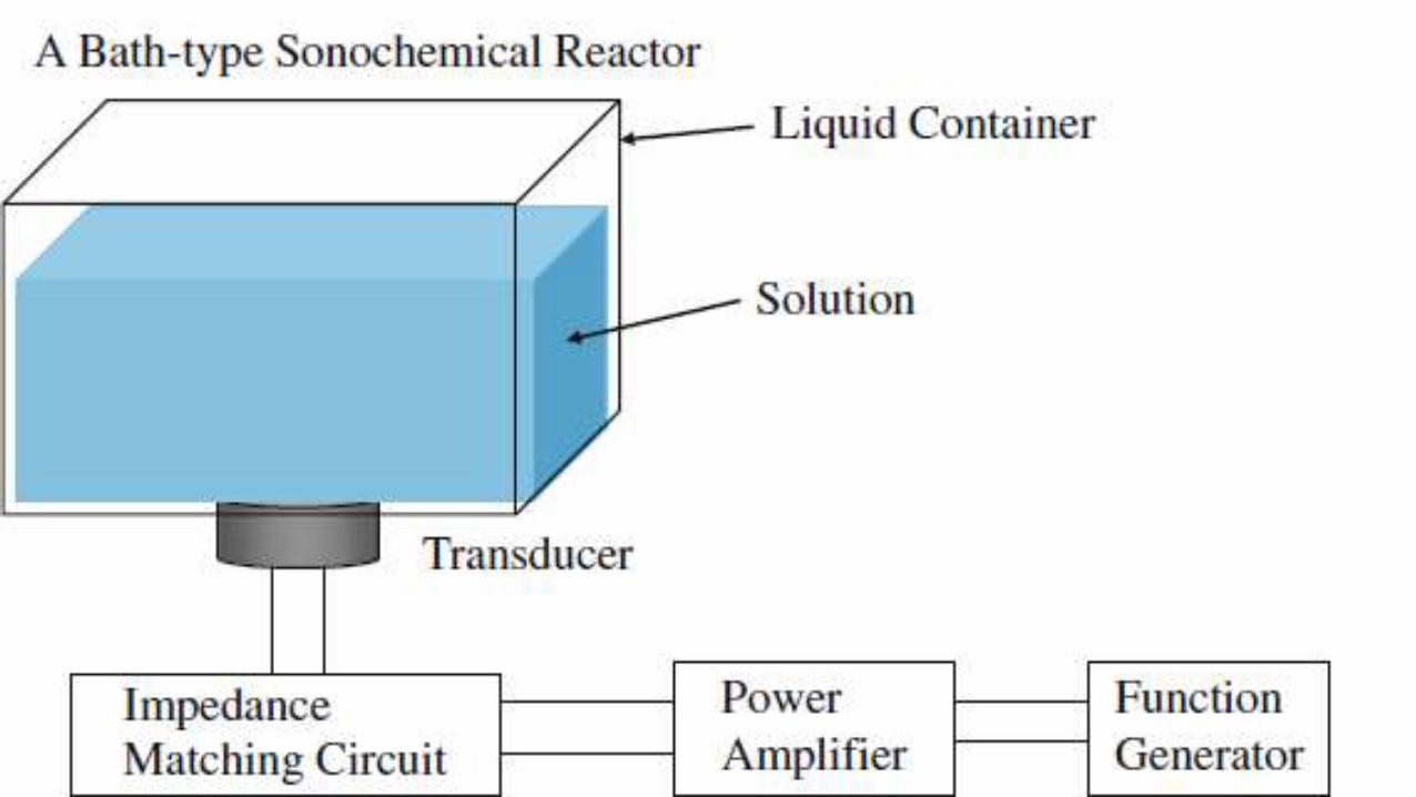

In a bath-type sonochemical reactor, a damped standing
wave is formed as shown in Fig. 1.13 [1]. Without
absorption of ultrasound, a pure standing wave is formed
because the intensity of the reflected wave from the liquid
surface is equivalent to that of the incident wave at any
distance from the transducer. Thus the minimum acoustic-
pressure amplitude is completely zero at each pressure
node where the incident and reflected waves are exactly
cancelled each other. In actual experiments, however,
there is absorption of ultrasound especially due to
cavitation bubbles. As a result, there appears a traveling
wave component because the intensity of the incident
wave is higher than that of the reflected wave. Thus, the
local minimum value of acoustic pressure amplitude is
non-zero as seen in Fig. 1.13. It should be noted that the
acoustic-pressure amplitude at the liquid surface (gas-
liquid interface) is always zero. In Fig. 1.13, there is the
liquid surface
Fig. 1.13 A damped standing wave under a condition
of resonance. k and x in the horizontal axis are wave
number and distance from the base of a bath-type
reactor, respectively

The electric system is the same as that in a bath-type reactor. An ultrasonic horn has a small tip from which high intensity ultrasound is radiated. The acoustic intensity increases as the surface area decreases if the total acoustic energy is the same. Thus, a horn tip produces an intense ultrasound.
Fig. 1.15 Calculated acoustic amplitude under an
ultrasonic horn as a function of the distance from the horn
tip on the symmetry axis

Tubular Clamp-on Multifrequency Liquid & gases Processing reactors
Pipe-Clamp solutions for liquid processing applications it is used to deliver uniform and homogenous ultrasonic energy over a large radiating surface. Such system are capable of delivering very high volumetric power (up to 1000 Watts per liter) to the liquid however due to the large radiating surface of the active element the surface power density is usually on the order of 0.5 to 2 Watts per centimeter square. Such power is providing very good cavitation effects and uniform power distribution throughout the reaction chamber

Applications that benefit from this arrangement are: Mixing/Homogenize is facilitated by uniform ultrasonic energy that generates significant cavitation distributed evenly throughout the reactor volume. Sonochemical Reactions accelerated by strong cavitation within an enclosed reactor.

Certainly we know that the two
techniques are complementary in that
acoustic cavitation provides a large
amount of concentrated energy that is
released by hotspots and that
microwaves provide dielectric heating
and selective heating of solid
particles. Thus one might expect
some advantages in the combination.
The main question about the
combined technology is how the two
separate technologies can be
combined given that any approach
involving placing a metal ultrasonic
horn inside a microwave zone is
hazardous.
There are few approaches:
• Use separate reactors one using ultrasound and another
using MW with a recirculating pump to allow the liquid to
be transferred from one reactor to another.
• Use a single reactor with both US and MW inside.
- Use uncoupled reactors

Hybrid loop reactor with two
different of horn set up: (A)
simultaneous US/MW irradiation,
(B) sequential US/MW irradiation
in separate vessels.
(Cintas, Tagliapietra et al. 2015)
1 US – non metalic horn;
2 MW oven
3 optical fiber thermometer
4 Pump
5 Flow-meter
6 Thermometer
7 Inlet and sampler
8 Heat exchaneger
9 external flask

Simultaneous US/MW irradiation using glass US horn and multimode MW applicator the source of ultrasound is a horn immersed in the reaction liquid within the MW cavity it cannot be metallic but alternate glass or ceramic horns are available.
If a ceramic or glass horn is used there is a limitation in that because of the characteristics of ceramic materials they cannot operate at high vibrational amplitudes and so the ultrasonic power of the hybrid reactor will be limited


Simultaneous MW and US irradiation, where MW irradiation is delivered into the liquid by a coaxial antenna

Bath hybrid reactor delivering
simultaneous irradiation from an
insulated MW antenna and a
titanium horn immersed in a
liquid. Reproduced with
permission from Ref. A.R. Hadj
Henni, C. Bacon, B. Hosten,
Acoustic generation in
piezoelectric materials by
microwave excitation, J. Acoust.
Soc. Am. 118 (2005) 2281–2288.

The ultrasound probe is not in
direct contact with the reactive
mixture. It is placed a distance
from the electromagnetic field
in order to avoid interactions
and short circuits. The
propagation of the ultrasound
waves in the reactor is made by
means of decaline introduced
into the double jacket (200 mL).
This liquid was chosen because
of its low viscosity which
induces good propagation of
ultrasound and its inertia
towards microwaves

Schematic drawing of the multi-mode
microwave system combined with
ultrasound

Sonoplasma
A stable plasma can be maintained in a liquid hydrocarbon which is exposed to MW (2.45 GHz, 100–200 W) which irradiates a pressurised quartz chamber where acoustic cavitation bubbles are generated by a titanium horn emitting at low ultrasonic frequency.
The protocol competes favourably with plasma generated by chemical vapour deposition, whose stability is problematic. The process is not yet routinely employed; although a recent application in environmental studies deserves attention (Fig. 5). The advanced oxidation of perfluorooctanoic acid (ca. 60% degradation) in aqueous media thus takes place after 90 s of plasma irradiation.

S. Horikoshi, S. Sato, M. Abe,
N. Serpone, A novel liquid
plasma AOP device
integrating microwaves and
ultrasounds and its evaluation
in defluorinating
perfluorooctanoic acid in
aqueous media, Ultrason.
Sonochem. 18 (2011) 938–
942.

New equipment purchased in project
Miniflow SS 200 W;
Multifunctional microwave device
Vibracell 750
Ultrasonic Bath
Pump dispensers

MW power 1-200 W Frequency 2430-2470 MHz
Miniflow 200 SS

Experiments types on the Miniflow
• Discontinuous at atmospheric pressure, cavity TE or TM
• Continuous, TE cavity
• Discontinuous under pressure TE cavity
• Combined MW + US
• Gas plasma


US power: 200 W 24 kHz; 50 mL MW power 0-200 W

50 mL 13 atm 190 0C


Surfatron


Components: MW Generator MW 0.6-3 kW, puls, continuu, Automatic impedance tuner Sliding short circuit Transition WR 340 to coaxial adaptor Water cooled dummy load
Monomode MW applicator


Vibracell 750
Features: US Power : 150-750 W Frequency: 20 kHz Titanium horn 13 mm Sample volume 10-250 mL Can be adjusted: - US power - Time - US Energy Additional equipment: Booster Extender

US bath Hilsonics 900
• Volume bath 18 L
• Volume utile 14 L
• Power for heating 600 W
• US Power 300W
• Frequency 30 kHz

Dosing pump Atlas

Equipment to be purchased
• Conventional pressure reactor G-S or L (MFC, pressure pump, etc.);
• US MMM clamp on;
• US glass horn


References • Álvarez, A., et al. (2017). "Measurement and correlation of the dielectric properties of a grape pomace
extraction media. Effect of temperature and composition." Journal of Food Engineering 197: 98-106.
• Anbar, M. (1964). "On the sonochemical formation of hydrogen peroxide in water." Journal of Physical Chemistry 68(2): 352-355.
• Brujan, E. A. and P. R. Williams (2006). "Cavitation Phenomena in Non-Newtonian Liquids." Chemical Engineering Research and Design 84(4): 293-299.
• Camelia Gabriel, S. G., Edward H. Grant, Edward H. Grant, Ben S. J. Halstead and D. Michael P. Mingos (1998). "Dielectric parameters relevant to microwave dielectric heating." Chem. Soc. Rev. 27: 213-224.
• Chemat, F. and G. Cravotto, Eds. (2013). Microwave-assisted Extraction for Bioactive Compounds. Food Engineering Series, Springer.
• Cintas, P., et al. (2015). "Enabling technologies built on a sonochemical platform: challenges and opportunities." Ultrason Sonochem 25: 8-16.
• Fitzgerald, M. E., et al. (1956). "Chemical Effects of Ultrasonics—``Hot Spot'' Chemistry." The Journal of Chemical Physics 25(5): 926-933.
• Gallego-Juárez, J. A. and K. F. Graff (2015). "Introduction to power ultrasonics." 1-6.
• Ganzler, K. and I. Szinai (1990). "Effective sample preparation method for extracting biologically active compounds from different matrices by a microwave technique." Journal of Chromatography 520: 257-262.
Gogate, P. R. and A. B. Pandit (2005). "A review and assessment of hydrodynamic cavitation as a technology for the future." Ultrason Sonochem 12(1-2): 21-27. Gude, V. G. (2015). "Synergism of microwaves and ultrasound for advanced biorefineries." Resource-Efficient Technologies 1(2): 116-125. Komorowska-Durka, M., et al. (2013). "Novel microwave reactor equipment using internal transmission line (INTLI) for efficient liquid phase chemistries: A study-case of polyester preparation." Chemical Engineering and Processing 69: 83-89. Lagha, A., et al. (1999). "Microwave - ultrasound combined reactor suitable for atmospheric sample preparation procedure of biological and chemical products." Analusis 27(5): 452-457. Lauterborn, W. and C.-D. Ohl (1997). "Cavitation bubble dynamics." Ultrasonics Sonochemistry 4(2): 65-75. Lee, C. S., et al. (2016). "Enhancing natural product extraction and mass transfer using selective microwave heating." Chemical Engineering Science 149: 97-103. Leonelli, C. and T. J. Mason (2010). "Microwave and ultrasonic processing: Now a realistic option for industry." Chemical Engineering and Processing: Process Intensification 49(9): 885-900. Loupy, A., Ed. (2002). Microwaves in Organic Synthesis, Wiley-VCH. Luque de Castro, M. D. and L. S. Castillo-Peinado (2016). Extraction, Separation, Component Modification, and Process Intensification. Innovative Food Processing Technologies. K. Knoerzer, P. Juliano and G. Smithers, Elsevier. Makino, K., et al. (1983). "Chemical effects of ultrasound on aqueous solutions. Formation of hydroxyl radicals and hydrogen atoms." Journal of Physical Chemistry 87(8): 1369-1377. Manoj Gupta and Wong Wai Leong (2007). Microwaves and Metals. Microwaves and Metals, Wiley.

Mason, T. J. (1999). Sonochemistry, Oxford University Press. Newman, A. P., et al. (1997). "An investigation into the ultrasonic treatment of polluted solids." Ultrasonics Sonochemistry 4(2): 153-156. Pankaj and M. Ashokkumar (2010). Theoretical and Experimental Sonochemistry Involving Inorganic Systems. Springer. Plesset, M. S. and R. B. Chapman (1971). "Collapse of an initially spherical vapor cavity in the neighborhood of a solid boundary." Journal of Fluid Mechanics 47: 283-290. Raymond J. Giguere, T. L. B., and Scott M. Duncan (1986). "APPLICATION OF COMERCIAL MICROWAVES OVENS TO ORGANIC SYNTHESIS." Tetrahedron Letters, 27(41): 4945-4948. Richard Gedye, F. S., Kenneth Westaway, Humera Ali, Lorraine Baldisera, and L. L. a. J. Rousell. (1986). "THE USE OF MICROWAVE OVENS FOR RAPID ORGANIC SYNTHESIS." Tetrahedron Letters 27(3): 279-282. Riesz, P., et al. (1985). "Free radical generation by ultrasound in aqueous and nonaqueous solutions." Environmental Health Perspectives VOL. 64: 233-252. Saleh, I. A., et al. (2016). "A possible general mechanism for ultrasound-assisted extraction (UAE) suggested from the results of UAE of chlorogenic acid from Cynara scolymus L. (artichoke) leaves." Ultrasonics Sonochemistry 31: 330-336. Schmitt, F. O., et al. (1929). "Oxidations promoted by ultrasonic radiation." Journal of the American Chemical Society 51(2): 370-375. Sipahioglu, O. and S. A. Barringer (2003). "Dielectric properties of vegetables and fruits as a function of temperature, ash, and moisture content." JOURNAL OF FOOD SCIENCE 68(1): 234-239. Stankiewicz, A. and J. Mouljin (2000). "Process Intensification Transforming Chemical Engineering." Chemical Engineering Progress: 22-34. Zhang, H. F., et al. (2011). "Microwave assisted extraction of secondary metabolites from plants: Current status and future directions." Trends in Food Science & Technology 22(12): 672-688.