Embed Size (px)
Citation preview

MX101PRODUCT REFERENCE GUIDE


MX101PRODUCT REFERENCE GUIDE
72E-171320-04Revision A
March 2015

ii MX101 PRODUCT REFERENCE GUIDE
No part of this publication may be reproduced or used in any form, or by any electrical or mechanical means, without permission in writing from Zebra. This includes electronic or mechanical means, such as photocopying, recording, or information storage and retrieval systems. The material in this manual is subject to change without notice.
The software is provided strictly on an “as is” basis. All software, including firmware, furnished to the user is on a licensed basis. Zebra grants to the user a non-transferable and non-exclusive license to use each software or firmware program delivered hereunder (licensed program). Except as noted below, such license may not be assigned, sub-licensed, or otherwise transferred by the user without prior written consent of Zebra. No right to copy a licensed program in whole or in part is granted, except as permitted under copyright law. The user shall not modify, merge, or incorporate any form or portion of a licensed program with other program material, create a derivative work from a licensed program, or use a licensed program in a network without written permission from Zebra. The user agrees to maintain Zebra’s copyright notice on the licensed programs delivered hereunder, and to include the same on any authorized copies it makes, in whole or in part. The user agrees not to decompile, disassemble, decode, or reverse engineer any licensed program delivered to the user or any portion thereof.
Zebra reserves the right to make changes to any software or product to improve reliability, function, or design. Zebra does not assume any product liability arising out of, or in connection with, the application or use of any product, circuit, or application described herein.
No license is granted, either expressly or by implication, estoppel, or otherwise under any Zebra Technologies Corporation, intellectual property rights. An implied license only exists for equipment, circuits, and subsystems contained in Zebra products.
Zebra Technologies CorporationLincolnshire, IL U.S.A.http://www.zebra.com
WarrantyFor the complete Zebra hardware product warranty statement, go to: http://www.zebra.com/warranty.

iii
Revision HistoryChanges to the original guide are listed below:
Change Date Description
-01 Rev. A 6/2013 Initial Release
-02 Rev. A 5/2014 Added:• Extra Low Frequency bar code• Extra High Frequency bar code• IBM Specification version (original and 2.2) section.
Updated:• Defaults
- Beeper Tone - High - Beeper Duration - Long- Timeout Between Decodes, Same Symbol - 0.6 seconds- Motion Detect Range - Short range- Range Restrict - 3 inches- Code 39 is disabled by default.
• Cross-reference errors.
-03 Rev. A 11/2014 Zebra branding; Speaker Wire Ferrite Placement instructions.
-04 Rev. A 2/2015 Zebra Rebranding

iv MX101 PRODUCT REFERENCE GUIDE
TABLE OF CONTENTS
Warranty ......................................................................................................................................... iiRevision History .............................................................................................................................. iii
About This GuideIntroduction ..................................................................................................................................... ixConfigurations................................................................................................................................. ix
Chapter Descriptions ...................................................................................................................... ixNotational Conventions................................................................................................................... xRelated Documents ........................................................................................................................ xiRecommended Services Information.............................................................................................. xi
Chapter 1: Getting StartedIntroduction .................................................................................................................................... 1-1Interfaces ....................................................................................................................................... 1-2Unpacking ...................................................................................................................................... 1-2Features ......................................................................................................................................... 1-3Installing and Configuring the Digital Scanner ............................................................................... 1-4
Chapter 2: Data CaptureIntroduction .................................................................................................................................... 2-1Beeper and Decode LED Signals .................................................................................................. 2-2Scanning ........................................................................................................................................ 2-3Decode Ranges ............................................................................................................................. 2-3
Chapter 3: USB InterfaceIntroduction .................................................................................................................................... 3-1USB Host Parameter ..................................................................................................................... 3-2IBM Specification Version .............................................................................................................. 3-3

ii MX101 PRODUCT REFERENCE GUIDE
Chapter 4: User Preferences & Miscellaneous OptionsIntroduction .................................................................................................................................... 4-1Phantom Scan Session ................................................................................................................. 4-1Scanning Sequence Examples ...................................................................................................... 4-2Errors While Scanning ................................................................................................................... 4-2User Preferences Parameter Defaults ........................................................................................... 4-2User Preferences ........................................................................................................................... 4-4
Set Default Parameter ............................................................................................................. 4-4Parameter Bar Code Scanning ................................................................................................ 4-5Lock/Unlock Parameter Scanning ............................................................................................ 4-6
Locking/Unlocking via the Host Interface ........................................................................... 4-6Beep After Good Decode ......................................................................................................... 4-7Beeper Tone ............................................................................................................................ 4-8Beeper Volume ........................................................................................................................ 4-9Beeper Duration ....................................................................................................................... 4-10Suppress Power-up Beeps ...................................................................................................... 4-10Trigger Modes .......................................................................................................................... 4-11Decode Session Timeout ......................................................................................................... 4-11Timeout Between Decodes, Same Symbol ............................................................................. 4-12Timeout Between Decodes, Different Symbols ....................................................................... 4-12Motion Detect Range ............................................................................................................... 4-13Range Restrict ......................................................................................................................... 4-14Presentation Mode Field of View ............................................................................................. 4-15Fuzzy 1D Processing ............................................................................................................... 4-16Mirrored Image ......................................................................................................................... 4-16Mobile Phone/Display Mode .................................................................................................... 4-17Validate Concatenated Parameter Bar Codes ......................................................................... 4-17Illumination Brightness ............................................................................................................. 4-18Decoding Illumination ............................................................................................................... 4-18Decode Aiming Pattern ............................................................................................................ 4-19
Miscellaneous Scanning Parameters ............................................................................................ 4-20Transmit Code ID Character .................................................................................................... 4-20Prefix/Suffix Values .................................................................................................................. 4-21Scan Data Transmission Format ............................................................................................. 4-22Report Version ......................................................................................................................... 4-24Report Scanner Manufacturing Information ............................................................................. 4-24Report Scan Engine Manufacturing Information ...................................................................... 4-24
Chapter 5: SymbologiesIntroduction .................................................................................................................................... 5-1Scanning Sequence Examples ...................................................................................................... 5-2Errors While Scanning ................................................................................................................... 5-2Symbology Parameter Defaults ..................................................................................................... 5-2Disable All Code Types ................................................................................................................. 5-8UPC/EAN ....................................................................................................................................... 5-9
Enable/Disable UPC-A ............................................................................................................. 5-9Enable/Disable UPC-E ............................................................................................................. 5-9Enable/Disable UPC-E1 ........................................................................................................... 5-10Enable/Disable EAN-8/JAN-8 .................................................................................................. 5-10Enable/Disable EAN-13/JAN-13 .............................................................................................. 5-11

Table of Contents iii
Enable/Disable Bookland EAN ................................................................................................ 5-11Bookland ISBN Format ............................................................................................................ 5-12Decode UPC/EAN/JAN Supplementals ................................................................................... 5-13User-Programmable Supplementals ........................................................................................ 5-16UPC/EAN/JAN Supplemental Redundancy ............................................................................. 5-16UPC/EAN/JAN Supplemental AIM ID Format .......................................................................... 5-17Transmit UPC-A Check Digit ................................................................................................... 5-18Transmit UPC-E Check Digit ................................................................................................... 5-18Transmit UPC-E1 Check Digit ................................................................................................. 5-19UPC-A Preamble ..................................................................................................................... 5-19UPC-E Preamble ..................................................................................................................... 5-20UPC-E1 Preamble ................................................................................................................... 5-21Convert UPC-E to UPC-A ........................................................................................................ 5-22Convert UPC-E1 to UPC-A ...................................................................................................... 5-22EAN-8/JAN-8 Extend ............................................................................................................... 5-23UCC Coupon Extended Code .................................................................................................. 5-23Coupon Report ......................................................................................................................... 5-24ISSN EAN ................................................................................................................................ 5-25
Code 128 ....................................................................................................................................... 5-26Enable/Disable Code 128 ........................................................................................................ 5-26Set Lengths for Code 128 ........................................................................................................ 5-26Enable/Disable GS1-128 (formerly UCC/EAN-128) ................................................................. 5-27Enable/Disable ISBT 128 ......................................................................................................... 5-28ISBT Concatenation ................................................................................................................. 5-29Check ISBT Table .................................................................................................................... 5-30ISBT Concatenation Redundancy ............................................................................................ 5-30
Code 39 ......................................................................................................................................... 5-31Enable/Disable Code 39 .......................................................................................................... 5-31Enable/Disable Trioptic Code 39 ............................................................................................. 5-31Convert Code 39 to Code 32 ................................................................................................... 5-32Code 32 Prefix ......................................................................................................................... 5-32Set Lengths for Code 39 .......................................................................................................... 5-33Code 39 Check Digit Verification ............................................................................................. 5-34Transmit Code 39 Check Digit ................................................................................................. 5-34Code 39 Full ASCII Conversion ............................................................................................... 5-35Code 39 Buffering - Scan & Store ............................................................................................ 5-36
Buffer Data ......................................................................................................................... 5-36Clear Transmission Buffer .................................................................................................. 5-36Transmit Buffer ................................................................................................................... 5-37Overfilling Transmission Buffer .......................................................................................... 5-37Attempt to Transmit an Empty Buffer ................................................................................. 5-37
Code 93 ......................................................................................................................................... 5-38Enable/Disable Code 93 .......................................................................................................... 5-38Set Lengths for Code 93 .......................................................................................................... 5-38
Code 11 ......................................................................................................................................... 5-40Code 11 ................................................................................................................................... 5-40Set Lengths for Code 11 .......................................................................................................... 5-40Code 11 Check Digit Verification ............................................................................................. 5-42Transmit Code 11 Check Digits ............................................................................................... 5-43
Interleaved 2 of 5 (ITF) .................................................................................................................. 5-44Enable/Disable Interleaved 2 of 5 ............................................................................................ 5-44

iv MX101 PRODUCT REFERENCE GUIDE
Set Lengths for Interleaved 2 of 5 ............................................................................................ 5-44I 2 of 5 Check Digit Verification ................................................................................................ 5-46Transmit I 2 of 5 Check Digit .................................................................................................... 5-46Convert I 2 of 5 to EAN-13 ....................................................................................................... 5-47
Discrete 2 of 5 (DTF) ..................................................................................................................... 5-48Enable/Disable Discrete 2 of 5 ................................................................................................. 5-48Set Lengths for Discrete 2 of 5 ................................................................................................ 5-48
Codabar (NW - 7) .......................................................................................................................... 5-50Enable/Disable Codabar .......................................................................................................... 5-50Set Lengths for Codabar .......................................................................................................... 5-50CLSI Editing ............................................................................................................................. 5-52NOTIS Editing .......................................................................................................................... 5-52Codabar Upper or Lower Case Start/Stop Characters Detection ............................................ 5-53
MSI ................................................................................................................................................ 5-54Enable/Disable MSI ................................................................................................................. 5-54Set Lengths for MSI ................................................................................................................. 5-54MSI Check Digits ..................................................................................................................... 5-56Transmit MSI Check Digit(s) .................................................................................................... 5-56MSI Check Digit Algorithm ....................................................................................................... 5-57
Chinese 2 of 5 ................................................................................................................................ 5-57Enable/Disable Chinese 2 of 5 ................................................................................................. 5-57
Matrix 2 of 5 ................................................................................................................................... 5-58Enable/Disable Matrix 2 of 5 .................................................................................................... 5-58Set Lengths for Matrix 2 of 5 .................................................................................................... 5-59Matrix 2 of 5 Check Digit .......................................................................................................... 5-60Transmit Matrix 2 of 5 Check Digit ........................................................................................... 5-60
Korean 3 of 5 ................................................................................................................................. 5-61Enable/Disable Korean 3 of 5 .................................................................................................. 5-61
Inverse 1D ..................................................................................................................................... 5-62Postal Codes ................................................................................................................................. 5-63
US Postnet ............................................................................................................................... 5-63US Planet ................................................................................................................................. 5-63Transmit US Postal Check Digit ............................................................................................... 5-64UK Postal ................................................................................................................................. 5-64Transmit UK Postal Check Digit ............................................................................................... 5-65Japan Postal ............................................................................................................................ 5-65Australia Post ........................................................................................................................... 5-66Australia Post Format .............................................................................................................. 5-67Netherlands KIX Code ............................................................................................................ 5-68USPS 4CB/One Code/Intelligent Mail ...................................................................................... 5-68UPU FICS Postal ..................................................................................................................... 5-69
GS1 DataBar ................................................................................................................................. 5-70GS1 DataBar ............................................................................................................................ 5-70GS1 DataBar Limited ............................................................................................................... 5-71GS1 DataBar Limited Security Level ....................................................................................... 5-72GS1 DataBar Expanded .......................................................................................................... 5-73Convert GS1 DataBar to UPC/EAN ......................................................................................... 5-73
Composite ...................................................................................................................................... 5-74Composite CC-C ...................................................................................................................... 5-74Composite CC-A/B ................................................................................................................... 5-74Composite TLC-39 ................................................................................................................... 5-75

Table of Contents v
UPC Composite Mode ............................................................................................................. 5-75Composite Beep Mode ............................................................................................................ 5-76GS1-128 Emulation Mode for UCC/EAN Composite Codes .................................................... 5-76
2D Symbologies ............................................................................................................................. 5-77Enable/Disable PDF417 ........................................................................................................... 5-77Enable/Disable MicroPDF417 .................................................................................................. 5-77Code 128 Emulation ................................................................................................................ 5-78Data Matrix ............................................................................................................................... 5-79Data Matrix Inverse .................................................................................................................. 5-79Decode Mirror Images (Data Matrix Only) ............................................................................... 5-80Maxicode .................................................................................................................................. 5-81QR Code .................................................................................................................................. 5-81QR Inverse ............................................................................................................................... 5-82MicroQR ................................................................................................................................... 5-82Aztec ........................................................................................................................................ 5-83Aztec Inverse ........................................................................................................................... 5-83
Redundancy Level ......................................................................................................................... 5-84Redundancy Level 1 ................................................................................................................ 5-84Redundancy Level 2 ................................................................................................................ 5-84Redundancy Level 3 ................................................................................................................ 5-84Redundancy Level 4 ................................................................................................................ 5-85
Security Level ................................................................................................................................ 5-86Intercharacter Gap Size ........................................................................................................... 5-87
Macro PDF Features ...................................................................................................................... 5-88Macro PDF User Indications .................................................................................................... 5-88Macro PDF Transmit / Decode Mode Symbols ........................................................................ 5-89Transmit Macro PDF Control Header ...................................................................................... 5-90Escape Characters .................................................................................................................. 5-90Flush Macro Buffer ................................................................................................................... 5-91Abort Macro PDF Entry ............................................................................................................ 5-91
Chapter 6: 123Scan2Introduction .................................................................................................................................... 6-1Communication with 123Scan2 ..................................................................................................... 6-1123Scan2 Requirements ............................................................................................................... 6-2Scanner SDK, Other Software Tools, and Videos ......................................................................... 6-2
Chapter 7: Advanced Data FormattingIntroduction .................................................................................................................................... 7-1
Chapter 8: Installing the MX101 Customer Side ScannerIntroduction .................................................................................................................................... 8-1Installing the MX101 on the Customer’s Right Side of the Tower Cover ....................................... 8-2Installing the MX101 on the Customer’s Left Side of the Tower Cover ......................................... 8-8Affixing the MX101 Identification Label to the MP6000 ................................................................. 8-10

vi MX101 PRODUCT REFERENCE GUIDE
Chapter 9: Maintenance, Troubleshooting, and Signal DescriptionsIntroduction .................................................................................................................................... 9-1Maintenance .................................................................................................................................. 9-1Troubleshooting ............................................................................................................................. 9-2
Report Software Version Bar Code .......................................................................................... 9-3Digital Scanner Signal Descriptions ............................................................................................... 9-4
Appendix A: Standard Default Parameters
Appendix B: Programming ReferenceSymbol Code Identifiers ................................................................................................................. B-1AIM Code Identifiers ...................................................................................................................... B-3
Appendix C: Sample Bar CodesCode 39 ......................................................................................................................................... C-1UPC/EAN ....................................................................................................................................... C-1
UPC-A, 100% ........................................................................................................................... C-1EAN-13, 100% ......................................................................................................................... C-2
Code 128 ....................................................................................................................................... C-2Interleaved 2 of 5 ........................................................................................................................... C-2GS1 DataBar-14 ............................................................................................................................ C-3PDF417 .......................................................................................................................................... C-3Data Matrix .................................................................................................................................... C-3Maxicode ....................................................................................................................................... C-3QR Code ........................................................................................................................................ C-4US Postnet ..................................................................................................................................... C-4UK Postal ....................................................................................................................................... C-4
Appendix D: Numeric Bar CodesNumeric Bar Codes ....................................................................................................................... D-1Cancel ............................................................................................................................................ D-2
Glossary
Index

Table of Contents vii

viii MX101 PRODUCT REFERENCE GUIDE

ABOUT THIS GUIDE
IntroductionThe MX101 Product Reference Guide provides general instructions for setting up, operating, maintaining, and troubleshooting the MX101 digital scanner.
ConfigurationsMX101-SR00004ZZWR: Customer Side Scanner
Chapter DescriptionsTopics covered in this guide are as follows:
• Chapter 1, Getting Started provides information about the scanner’s features, and setting up, installing, and configuring the digital scanner.
• Chapter 2, Data Capture provides beeper and LED definitions, techniques involved in capturing bar codes, general instructions and tips about scanning, and decode range information.
• Chapter 4, User Preferences & Miscellaneous Options describes features frequently used to customize how data transmits to the host device and programming bar codes for selecting user preference features for the decoder.
• Chapter 3, USB Interface describes how to set up the decoder with a USB host.
• Chapter 5, Symbologies describes all symbology features and provides programming bar codes for selecting these features for the decoder.
• Chapter 6, 123Scan2 describes this PC-based scanner configuration tool which enables rapid and easy customized setup of scanners.
• Chapter 7, Advanced Data Formatting briefly describes ADF, a means of customizing data before transmission to the host device, and includes a reference to the ADF Programmer Guide.
• Chapter 8, Installing the MX101 Customer Side Scanner provides the steps to install the MX101 into the MP6000, and affix the MX101 identification label.

x MX101 PRODUCT REFERENCE GUIDE
• Chapter 9, Maintenance, Troubleshooting, and Signal Descriptions provides suggested digital scanner maintenance, troubleshooting, technical specifications, and signal descriptions (pinouts).
• Appendix A, Standard Default Parameters provides a table of all host devices and miscellaneous defaults.
• Appendix B, Programming Reference provides a table of AIM code identifiers, ASCII character conversions, and keyboard maps.
• Appendix C, Sample Bar Codes includes sample bar codes of various code types.
• Appendix D, Numeric Bar Codes includes the numeric bar codes to scan for parameters requiring specific numeric values.
• Appendix E, ASCII Character Sets provides ASCII character value tables.
Notational ConventionsThe following conventions are used in this document:
• Italics are used to highlight the following:
• Chapters and sections in this and related documents
• Dialog box, window and screen names
• Drop-down list and list box names
• Check box and radio button names
• Bold text is used to highlight the following:
• Key names on a keypad
• Button names on a screen.
• bullets (•) indicate:
• Action items
• Lists of alternatives
• Lists of required steps that are not necessarily sequential
• Sequential lists (e.g., those that describe step-by-step procedures) appear as numbered lists.
• Throughout the programming bar code menus, asterisks (*) are used to denote default parameter settings.
*Baud Rate 9600 Feature/Option* Indicates Default

About This Guide xi
Related Documents• MX101 CUSTOMER SIDE SCANNER (CSS) INSTALLATION GUIDE, p/n MN000051Axx, provides
installation instructions to connect the MX101 CSS to the MP6000 (also included in this guide).
• MX101 IDENTIFICATION LABEL, p/n MN000049Axx, provides installation information for the MX101 warranty label (also included in this guide).
• MP6000 MULTI-PLANE IMAGING SCANNER INTEGRATOR GUIDE, p/n 72E-163525-xx, provides MP6000 site preparation and installation information, as well as MP6000 operating instructions.
• MP6000 MULTI-PLANE IMAGING SCANNER BAR CODE PROGRAMMING GUIDE,p/n 72E-172633-xx, provides bar codes for MP6000 configuration.
• MP6000 MULTI-PLANE IMAGING SCANNER REGULATORY GUIDE, p/n 72-171321-xx, provides domestic and international regulatory information, and China RoHS information.
• Advanced Data Formatting Programmer Guide, p/n 72E-69680-xx, provides information on ADF, a means of customizing data before transmission to a host.
For the latest version of this guide and all Zebra guides, go to: http://www.zebra.com/support.
Recommended Services InformationIf you have a problem using the equipment, contact your facility's technical or systems support. If there is a problem with the equipment, they will contact the Zebra Customer Support Center at: http://www.zebra.com/support.
When contacting Zebra support, please have the following information available:
• Serial number of the unit
• Model number or product name
• Software type and version number
Zebra responds to calls by e-mail, telephone or fax within the time limits set forth in service agreements.
If your problem cannot be solved by the Zebra Customer Support Center, you may need to return your equipment for servicing and will be given specific directions or a Field Service Technician may be sent to your location to perform the repair, depending on your level of entitlement set forth in the service agreement. Zebra is not responsible for any damages incurred during shipment if the approved shipping container is not used. Shipping the units improperly can possibly void the warranty.
If you purchased your business product from a Zebra business partner, please contact that business partner for support.
Zebra recommends the following Service options to keep the MP6000 operating at peak performance throughout its lifecycle:
• Service from the Start with Advance Exchange Support (available for scanner-only configurations).
• Service from the Start with On Site System Support (available for scanner-only and scanner/scale configurations).

xii MX101 PRODUCT REFERENCE GUIDE

CHAPTER 1 GETTING STARTED
IntroductionThe MX101 combines superior 1D and 2D omnidirectional bar code scanning with an advanced feature set in a compact design. The digital scanner was designed to integrate seamlessly into the MP6000 multi-plane imaging scanner, and is optimized for scanning customer cell phones and loyalty cards.
This chapter provides information about the scanner’s features, and setting up, installing, and configuring the digital scanner.

1 - 2 MX101 PRODUCT REFERENCE GUIDE
InterfacesThe MX101 digital scanner connects to the MP6000 via a single USB cable, and defaults to the SNAPI interface type.
UnpackingRemove the scanner, rear cover, and USB cable from the packing and inspect for damage. If the scanner was damaged in transit, contact Zebra Customer Support Center. See page xi for contact information. KEEP THE PACKING. It is the approved shipping container and should be used if the equipment ever needs to be returned for servicing.

Getting Started 1 - 3
FeaturesThe MX101 is integrated into the multi-plane imaging scanner tower on either the left or right side. The multi-plane imaging scanner requires a custom tower cover replacement.
The scanner has the following features:
• Scans paper and mobile phone 1D/2D loyalty cards and coupons
• Auditory and visual feedback on decode
• Auto wakeup upon object presentation.
Figure 1-1 Scanner Features
MX101 Scan WIndow
Removable Tower Cover
Integrated MX101
MP6000
Customized MX101 Tower Cover
Decode LED

1 - 4 MX101 PRODUCT REFERENCE GUIDE
Installing and Configuring the Digital ScannerTo configure the digital scanner use the bar codes included in this manual, or use the 123Scan2 configuration program (see Chapter 6, 123Scan2). Also see Chapter 4, User Preferences & Miscellaneous Options, Chapter 5, Imaging Preferences, and Chapter 5, Symbologies for information about programming the digital scanner using bar code menus.
See Chapter 8, Installing the MX101 Customer Side Scanner for instructions to install:
• the MX101 into the MP6000 multi-plane imaging scanner.
• the MX101 identification label.

CHAPTER 2 DATA CAPTURE
IntroductionThis chapter provides beeper and LED definitions, techniques involved in capturing bar codes, general instructions and tips about scanning, and decode range information.

2 - 2 MX101 Product Reference Guide
Beeper and Decode LED SignalsThe digital scanner has a visual green LED indicator and issues different beep sequences, and patterns to indicate status. Table 2-1 defines beep sequences that occur during both normal scanning and while programming the digital scanner.
Table 2-1 User Interface Indications
DescriptionIndication
Beeper Decode LED
No Decode No Audible Sound No Light
Decode Middle Tone Flash of Light
Bootup Low Tone, Middle Tone, High Tone No Light
Transmission Error Four Low Tones No Light
Entry Error Low Tone, High Tone Flash of Light
Defaults Set High Tone, Low Tone, High Tone, Low Tone
Flash of LightParameter Entered
Number Entry Expected High Tone, Low Tone Flash of Light

Data Capture 2 - 3
ScanningFor standard operation, the scanner automatically decodes bar codes that are presented in its field of view.
Figure 2-1 Scanning
Decode RangesTable 2-2 Decode Ranges
Symbol Specification
Typical Working Ranges (from side of MP6000)
Near Far
UPCA
13.0mil
80% MRD
Contact Read 9.55 in./ 24.3 cm
PDF417
6.67mil
80% MRD
Contact Read 2.75 in./7.0 cm
Code 128
15.0mil
80% MRD
Contact Read 7.5 in./19.1 cm

2 - 4 MX101 Product Reference Guide

CHAPTER 3 USB INTERFACE
IntroductionThe scanner connects directly to a USB port on the MP6000. No additional power supply is required.
Throughout this guide, the asterisks (*) indicate the default values.
Table 3-1 USB Interface Default Table
Parameter Default Page Number
USB Host Parameter *Symbol Native API (SNAPI) with Imaging Interface 3-2
IBM Specification Version Original Specification 3-3
*Symbol Native API (SNAPI) with Imaging Interface Feature/Option*Indicates Default

3 - 2 MX101 PRODUCT REFERENCE GUIDE
USB Host ParameterWhen the MX101 connects to the MP6000, the MP6000 manages the device using the best fit host type to maximize communication between the two devices. Host types should not change. The default host type is SNAPI with Imaging. Scan SNAPI without Imaging to change the option.
NOTES 1.See Appendix A, Standard Default Parameters for all user preferences, symbologies, and miscellaneous default parameters.
2.When changing USB Device Types, the scanner automatically resets and issues the standard startup beep sequences.
*Symbol Native API (SNAPI) with Imaging Interface
Symbol Native API (SNAPI) without Imaging Interface

USB Interface 3 - 3
IBM Specification VersionThe IBM USB interface specification version selected defines how code types are reported over the IBM USB interface.
*Original Specification
Version 2.2

3 - 4 MX101 PRODUCT REFERENCE GUIDE

CHAPTER 4 USER PREFERENCES & MISCELLANEOUS OPTIONS
IntroductionYou can program the digital scanner to perform various functions, or activate different features. This chapter describes each user preference feature and provides programming bar codes for selecting these features.
The digital scanner ships with the settings shown in Table 4-1 on page 4-2 (also see Appendix A, Standard Default Parameters for all host device and miscellaneous defaults). If the default values suit requirements, programming is not necessary.
To set feature values, scan a single bar code or a short bar code sequence. The settings are stored in non-volatile memory and are preserved even when the digital scanner is powered down.
To return all features to default values, scan the *Restore Defaults on page 4-4. Throughout the programming bar code menus, asterisks indicate (*) default values.
Phantom Scan SessionThe Phantom Scan Session feature places the system into a known state for two seconds immediately after the power-up beep sequence in order to decode a parameter bar code without intervention, and regardless of existing settings and mode. This allows the user to scan a Set Defaults, or other parameter bar code without triggering the decoder or initiating a host scan session in order to return an unresponsive system to its factory default settings. Aim and illumination are turned off, and Phantom Scan exits upon a host command or successful decode.
*High Volume(00h)
Feature/Option* Indicates Default
Option Hex Value

4 - 2 MX101 PRODUCT REFERENCE GUIDE
Scanning Sequence ExamplesIn most cases, scanning one bar code sets the parameter value. For example, to set the beeper tone to high, scan the High Frequency (beeper tone) bar code listed under Beeper Tone on page 4-8. The scanner issues a fast warble beep and the LED turns green, signifying a successful parameter entry.
Other parameters, such as Data Transmission Formats, require scanning several bar codes. See these parameter descriptions for this procedure.
Errors While ScanningUnless otherwise specified, to correct an error during a scanning sequence, just re-scan the correct parameter.
User Preferences Parameter DefaultsTable 4-1 lists defaults for user preferences parameters. To change any parameter value, scan the appropriate bar code(s) provided in the User Preferences section beginning on page 4-4.
NOTE See Appendix A, Standard Default Parameters for all user preferences, hosts, symbologies, and miscellaneous default parameters.
Table 4-1 User Preferences Default Table
Parameter Parameter Number Default Page
Number
User Preferences
Set Default Parameter Restore Defaults 4-4
Parameter Bar Code Scanning ECh Enable 4-5
Lock Parameter Scanning F2h 22h Disable 4-6
Unlock Parameter Scanning F2h 23h Disable 4-6
Beep After Good Decode 38h Enable 4-7
Beeper Tone 91h High 4-8
Beeper Volume 8Ch High 4-9
Beeper Duration F1h 74h Long 4-10
Suppress Power-up Beeps F1h D1h Do not suppress 4-10
Trigger Modes 8Ah Presentation Mode 4-11
Decode Session Timeout 88h 9.9 Sec 4-11
Timeout Between Decodes, Same Symbol 89h 0.6 Sec 4-12
Timeout Between Decodes, Different Symbols 90h 0.2 Sec 4-12
Motion Detect Range F2h 3Bh Short Range 4-13

User Preferences & Miscellaneous Options 4 - 3
Range Restrict F1h 75h 3 inches 4-14
Presentation Mode Field of View F1h 61h Medium Field of View 4-15
Fuzzy 1D Processing F1h 02h Enable 4-16
Mirrored Image F1h 70h Disable 4-16
Mobile Phone/Display Mode F1h CCh Enable 4-17
Validate Concatenated Parameter Bar Codes F1h B4h Disable 4-17
Illumination Brightness F1h 9Dh 6 4-18
Decoding Illumination F0h 2Ah Enable 4-18
Decode Aiming Pattern F0h 32h Disable 4-18
Miscellaneous Scanning Parameters
Transmit Code ID Character 2Dh None 4-20
SSI Prefix Value 69h <CR> 4-21
SSI Suffix 1 Value
SSI Suffix 2 Value
68h
6Ah
<CR>
<CR>
4-21
Scan Data Transmission Format EBh Data as is 4-22
Report Version 4-24
Report scanner Manufacturing Version 4-24
Report Scan Engine Manufacturing Version 4-24
Table 4-1 User Preferences Default Table
Parameter Parameter Number Default Page
Number

4 - 4 MX101 PRODUCT REFERENCE GUIDE
User Preferences
Set Default Parameter
You can reset the scanner to two types of defaults: factory defaults or custom defaults. Scan the appropriate bar code below to reset the scanner to its default settings and/or set its current settings as custom defaults.
• Restore Defaults - Scan this bar code to reset all default parameters as follows.
• If you previously set custom defaults by scanning Write to Custom Defaults, scan Restore Defaults to retrieve and restore the scanner’s custom default settings.
• If you did not set custom defaults, scan Restore Defaults to restore the factory default values listed in Table A-1.
• Set Factory Defaults - Scan this bar code to restore the factory default values listed in Table A-1. This deletes any custom defaults set.
• Write to Custom Defaults - Scan this bar code to set the current scanner settings as custom defaults. Once set, you can recover custom default settings by scanning Restore Defaults.
*Restore Defaults
Set Factory Defaults
Write to Custom Defaults

User Preferences & Miscellaneous Options 4 - 5
Parameter Bar Code Scanning
Parameter # ECh
To disable the decoding of parameter bar codes, including the Set Defaults parameter bar codes, scan the Disable Parameter Scanning bar code below. To enable decoding of parameter bar codes, scan Enable Parameter Scanning.
*Enable Parameter Scanning(01h)
Disable Parameter Scanning(00h)

4 - 6 MX101 PRODUCT REFERENCE GUIDE
Lock/Unlock Parameter Scanning
Lock: Parameter # F2h 22h
Unlock: Parameter # F2h 23h
This feature locks parameter settings with a 4-digit code to prevent the user from changing parameter values by scanning parameter bar codes. This provides an added level of security not offered via Disable Parameter Scanning.
After locking parameter settings, the only parameter bar code that is accepted is Unlock with the correct code.
To lock parameter scanning:
1. Scan the Lock bar code.
2. Scan four bar codes from Appendix D, Numeric Bar Codes that represent the desired code. Enter leading zeros for numbers below 1000, e.g., to program a code of 29, enter 0, 0, 2, 9. A "lock" beep sounds (two long high beeps) in addition to the parameter entry beep.
To unlock parameter scanning:
1. Scan the Unlock bar code.
2. Scan four bar codes from Appendix D, Numeric Bar Codes that represent the correct code. An "unlock" beep sounds (two long low beeps) in addition to the parameter entry beep. Entering an incorrect code results in a parameter error beep.
Locking/Unlocking via the Host Interface
Parameter scanning can also be locked or unlocked using a host interface such as SSI or USB SNAPI. To lock parameter scanning using the host interface, store a 4-digit code within the range of 1-9999 in the Lock parameter. Values outside this range are ignored. To unlock parameter scanning, store this code in the Unlock parameter. To persist the lock/unlock status through a power cycle, make this parameter value permanent.
NOTE Parameter Bar Code Scanning must be enabled in order to scan the Lock parameter bar code. Once parameter scanning is locked, scanning the Enable or Disable Parameter Scanning bar code results in a parameter error beep.
Lock
Unlock
NOTE Parameter values can be changed via host interface commands even when parameter scanning is locked.

User Preferences & Miscellaneous Options 4 - 7
Beep After Good Decode
Parameter # 38h
Scan a bar code below to select whether or not the scanner issues a beep signal after a good decode. If selecting Do Not Beep After Good Decode, beeper signals still occur during parameter menu scanning and to indicate error conditions.
*Beep After Good Decode(Enable)
(01h)
Do Not Beep After Good Decode(Disable)
(00h)

4 - 8 MX101 PRODUCT REFERENCE GUIDE
Beeper Tone
Parameter # 91h
To select a decode beep frequency (tone), scan the Low Frequency, Medium Frequency, or High Frequency bar code.
Low Frequency(02h)
Medium Frequency(01h)
*High Frequency(00h)
Extra Low Frequency(0Ch)
Extra High Frequency(0Dh)

User Preferences & Miscellaneous Options 4 - 9
Beeper Volume
Parameter # 8Ch
To select a beeper volume, scan the Low Volume, Medium Volume, or High Volume bar code.
Low Volume(02h)
Medium Volume(01h)
*High Volume(00h)

4 - 10 MX101 PRODUCT REFERENCE GUIDE
Beeper Duration
Parameter # F1h 74h
To select the duration for the beeper, scan one of the following bar codes.
Suppress Power-up Beeps
Parameter # F1h D1h
Select whether or not to suppress the scanner’s power-up beeps.
Short(00h)
Medium(01h)
* Long(02h)
* Do Not Suppress Power-up Beeps(00h)
Suppress Power-up Beeps(01h)

User Preferences & Miscellaneous Options 4 - 11
Trigger Modes
Parameter # 8Ah• Presentation Mode - When the scanner detects an object in its field of view, it triggers and attempt to
decode. The range of object detection does not vary under normal lighting conditions. This applies to decode mode only.
• Host - A host command issues the triggering signal. The scanner interprets an actual trigger pull as a Level triggering option.
Decode Session Timeout
Parameter # 88h
This parameter sets the maximum time decode processing continues during a scan attempt. It is programmable in 0.1 second increments from 0.5 to 9.9 seconds. The default timeout is 9.9 seconds.
To set a Decode Session Timeout, scan the bar code below. Next, scan two numeric bar codes from Appendix D, Numeric Bar Codes that correspond to the desired on time. Provide a leading zero for single digit numbers. For example, to set a Decode Session Timeout of 0.5 seconds, scan the bar code below, then scan the 0 and 5 bar codes. To correct an error or change the selection, scan Cancel on page D-2.
* Presentation Mode(07h)
Host(08h)
Decode Session Timeout

4 - 12 MX101 PRODUCT REFERENCE GUIDE
Timeout Between Decodes, Same Symbol
Parameter # 89h
Use this option in Presentation Mode to prevent multiple reads of a symbol left in the scanner’s field of view. The timeout begins when you remove the symbol from the field of view.
To select the timeout between decodes for the same symbol, available in 0.1 second increments from 0.0 to 9.9 seconds, scan the bar code below, then scan two numeric bar codes from Appendix D, Numeric Bar Codes that correspond to the desired interval. The default interval is 0.6 seconds.
Timeout Between Decodes, Different Symbols
Parameter # 90h
Use this option in Presentation Mode to control the time the scanner is inactive between decoding different symbols. It is programmable in 0.1 second increments from 0.1 to 9.9 seconds. The default is 0.2 seconds.
To select the timeout between decodes for different symbols, scan the bar code below, then scan two numeric bar codes from Appendix D, Numeric Bar Codes that correspond to the desired interval, in 0.1 second increments.
NOTE The Timeout Between Decodes, Same Symbol value must be greater than the Timeout Between Decodes, Different Symbols value.
Timeout Between Decodes, Same Symbol
NOTE The Timeout Between Decodes, Different Symbols value cannot be greater than or equal to the Timeout Between Decodes, Same Symbol or the Decode Session Timeout on page 4-11 value.
Timeout Between Decodes, Different Symbols

User Preferences & Miscellaneous Options 4 - 13
Motion Detect Range
Parameter # F2h 3Bh
This parameter controls the distance, or range, at which the scanner detects object motion and then triggers while in Presentation Mode.
Full Range(02h)
Medium Range(05h)
* Short Range(0Ah)

4 - 14 MX101 PRODUCT REFERENCE GUIDE
Range Restrict
Parameter # F1h 75hAttribute # 629
Range restriction can be enabled by setting a parameter value greater than zero and disabled when setting a value of zero. When enabled it allows for reducing the reading range of a UPC family bar code to a restricted range in inches. The parameter value represents a maximum reading range of a 100% UPC family bar code.
The value is approximate and small variations to a restriction limit are to be expected.
When scanning bar codes of different densities (i.e., 60%, 80%, and 200%) the range limit is scaled up/down proportional to the density.
Disable(00h)
* 3 inches(03h)
5 inches(05h)
7 inches(07h)

User Preferences & Miscellaneous Options 4 - 15
Presentation Mode Field of View
Parameter # F1h 61h
In Presentation Mode, the scanner searches for a bar code in the region around the aiming pattern’s center.
To search for a bar code in a smaller region around the aiming pattern in order to speed search time, select Small Field of View, or to search a larger area, select Full Field of View.
Small Field of View(00h)
*Medium Field of View(01h)
Full Field of View(02h)

4 - 16 MX101 PRODUCT REFERENCE GUIDE
Fuzzy 1D Processing
Parameter # F1h 02h
This option is enabled by default to optimize decode performance on 1D bar codes, including damaged and poor quality symbols. Disable this only if you experience time delays when decoding 2D bar codes, or in detecting a no decode.
Mirrored Image
Parameter # F1h 70h
Enable this to scan images in reverse, or mirrored, as if seen through a mirror. This mode is useful in applications requiring scanning through a mirror and using symbologies that do not decode in reverse.
Enabling this mode when using snapshot mode transmits images as mirrored images.
*Enable Fuzzy 1D Processing(01h)
Disable Fuzzy 1D Processing(00h)
*Disable Mirrored Image(00h)
Enable Mirrored Image(01h)
User Preferences & Miscellaneous Options 4 - 17
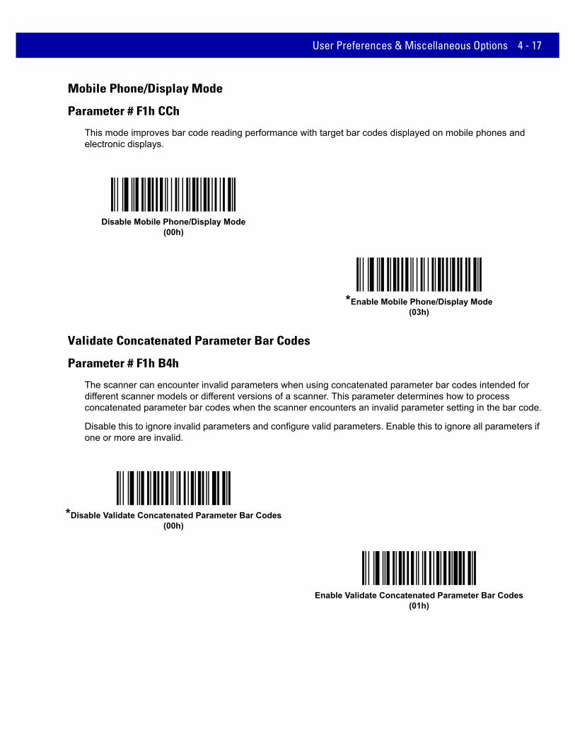
Mobile Phone/Display Mode
Parameter # F1h CCh
This mode improves bar code reading performance with target bar codes displayed on mobile phones and electronic displays.
Validate Concatenated Parameter Bar Codes
Parameter # F1h B4h
The scanner can encounter invalid parameters when using concatenated parameter bar codes intended for different scanner models or different versions of a scanner. This parameter determines how to process concatenated parameter bar codes when the scanner encounters an invalid parameter setting in the bar code.
Disable this to ignore invalid parameters and configure valid parameters. Enable this to ignore all parameters if one or more are invalid.
Disable Mobile Phone/Display Mode(00h)
*Enable Mobile Phone/Display Mode(03h)
*Disable Validate Concatenated Parameter Bar Codes(00h)
Enable Validate Concatenated Parameter Bar Codes(01h)

4 - 18 MX101 PRODUCT REFERENCE GUIDE
Illumination Brightness
Parameter # F1h 9Dh
This feature sets the brightness of the illumination by altering LED power. The default is 10, which is maximum LED brightness. For values from 1 to 10, LED brightness varies from lowest to highest level of brightness. The default is 6.
To program Illumination Brightness, scan this bar code followed by two numeric bar codes in Appendix D, Numeric Bar Codes that correspond to the value of desired illumination brightness. For example, to set Illumination Brightness to 6, scan the bar code below followed by the 0 and 6 bar codes.
Decoding Illumination
Parameter # F0h 2Ah
Selecting Enable Decoding Illumination causes the scanner to turn on illumination every image capture to aid decoding. Select Disable Decoding Illumination to prevent the scanner from using decoding illumination.
Enabling illumination usually results in superior images. The effectiveness of illumination decreases as the distance to the target increases.
Illumination Brightness
*Enable Decoding Illumination(01h)
Disable Decoding Illumination(00h)

User Preferences & Miscellaneous Options 4 - 19
Decode Aiming Pattern
Parameter # F0h 32hSelect Enable Decode Aiming Pattern to project the aiming pattern during bar code capture, or Disable Decode Aiming Pattern to turn the aiming pattern off.
Enable Decode Aiming Pattern(02h)
* Disable Decode Aiming Pattern(00h)

4 - 20 MX101 PRODUCT REFERENCE GUIDE
Miscellaneous Scanning Parameters
Transmit Code ID Character
Parameter # 2Dh
A Code ID character identifies the code type of a scanned bar code. This is useful when decoding more than one code type. In addition to any single character prefix already selected, the Code ID character is inserted between the prefix and the decoded symbol.
Select no Code ID character, a Symbol Code ID character, or an AIM Code ID character. For Code ID Characters, see Symbol Code Identifiers on page B-1 and AIM Code Identifiers on page B-3.
Symbol Code ID Character(02h)
AIM Code ID Character(01h)
*None(00h)

User Preferences & Miscellaneous Options 4 - 21
Prefix/Suffix Values
Key Category Parameter # P = 63h, S1 = 62h, S2 = 64hDecimal Value Parameter # P = 69h, S1 = 68h, S2 = 6Ah
You can append a prefix and/or one or two suffixes to scan data for use in data editing. To set a value for a prefix or suffix, scan the prefix or suffix bar code below, then scan a four-digit number (i.e., four bar codes from Appendix D, Numeric Bar Codes) that corresponds to that value. The first digit defines the key category (type of character to send) and is stored in the key category parameter. The remaining three digits define the value of the character and are stored in the decimal value parameter. Be sure to use both key category and decimal value parameters to define the prefix/suffix value. See Table E-1 on page E-1 for the four-digit codes.
When using host commands to set the prefix or suffix, set the key category parameter to 1, then set the 3-digit decimal value. See Table E-1 on page E-1 for the four-digit codes.
To correct an error or change a selection, scan Cancel on page D-2.
NOTE To use Prefix/Suffix values, set the Scan Data Transmission Format on page 4-22.
Scan Prefix(07h)
Scan Suffix 1(06h)
Scan Suffix 2(08h)

4 - 22 MX101 PRODUCT REFERENCE GUIDE
Scan Data Transmission Format
Parameter # EBh
To change the scan data format, scan one of the following eight bar codes corresponding to the desired format.
To set values for the prefix and/or suffix, see Prefix/Suffix Values on page 4-21.
NOTE If using this parameter do not use ADF rules to set the prefix/suffix.
*Data As Is(00h)
<DATA> <SUFFIX 1>(01h)
<DATA> <SUFFIX 2>(02h)
<DATA> <SUFFIX 1> <SUFFIX 2>(03h)
<PREFIX> <DATA >(04h)

User Preferences & Miscellaneous Options 4 - 23
Scan Data Transmission Format (continued)
<PREFIX> <DATA> <SUFFIX 1>(05h)
<PREFIX> <DATA> <SUFFIX 2>(06h)
<PREFIX> <DATA> <SUFFIX 1> <SUFFIX 2>(07h)

4 - 24 MX101 PRODUCT REFERENCE GUIDE
Report Version
Scan the bar code below to report the version of software currently installed in the scanner.
Report Scanner Manufacturing Information
Scan the bar code below to report the part number, serial number, and manufacture date of the scanner.
Report Scan Engine Manufacturing Information
Scan the bar code below to report the part number, serial number, and manufacture date of the scan engine.
Report Software Version
Report Scanner Manufacturing Information
Report Engine Manufacturing Information

CHAPTER 5 SYMBOLOGIES
IntroductionThis chapter describes symbology features and provides the programming bar codes for selecting these features. Before programming, follow the instructions in Chapter 1, Getting Started.
The scanner is shipped with the settings shown in Table 5-1 on page 5-2 (also see Appendix A, Standard Default Parameters for all host device and miscellaneous defaults). If the default values suit requirements, programming is not necessary.
There are two ways to change a parameter value:
• Scan the appropriate bar codes in this guide. These new values replace the standard default values in memory.
• For USB SNAPI hosts, send a “parameter send” command from the host system. Hexadecimal parameter numbers are shown in this chapter below the parameter title, and options are shown in parenthesis beneath the accompanying bar codes.
Select a host type (see each host chapter for specific host information) after the power-up beeps sound. This is only necessary upon the first power-up when connected to a new host.
To return all features to default values, scan the Set Default Parameter on page 4-4. Throughout the programming bar code menus, asterisks (*) indicate default values.
*Enable UPC-A(01h)
Feature/Option* Indicates Default
Option Hex Value

5 - 2 MX101 PRODUCT REFERENCE GUIDE
Scanning Sequence ExamplesIn most cases, scanning one bar code sets the parameter value. For example, to transmit bar code data without the UPC-A check digit, simply scan the Do Not Transmit UPC-A Check Digit bar code under Transmit UPC-A Check Digit on page 5-18. The scanner issues a fast warble beep and the LED turns green, signifying a successful parameter entry.
Other parameters, such as Set Length(s) for D 2 of 5 require scanning several bar codes. See the individual parameter, such as Set Length(s) for D 2 of 5, for this procedure.
Errors While ScanningUnless otherwise specified, to correct an error during a scanning sequence, just re-scan the correct parameter.
Symbology Parameter DefaultsTable 5-1 lists the defaults for all symbologies parameters. To change the default values, scan the appropriate bar codes in this guide. These new values replace the standard default values in memory. To recall the default parameter values, scan the Set Default Parameter on page 4-4.
NOTE See Appendix A, Standard Default Parameters for all user preferences, hosts, and miscellaneous default parameters.
Table 5-1 Parameter Defaults
Parameter Parameter Number Default Page
Number
Disable All Code Types 5-8
UPC/EAN
UPC-A 01h Disable 5-9
UPC-E 02h Disable 5-9
UPC-E1 0Ch Disable 5-10
EAN-8/JAN 8 04h Disable 5-10
EAN-13/JAN 13 03h Disable 5-11
Bookland EAN 53h Disable 5-11
Bookland ISBN Format F1h 40h ISBN-10 5-12
Decode UPC/EAN/JAN Supplementals (2 and 5 digits) 10h Ignore 5-14
User-Programmable Supplementals
Supplemental 1:
Supplemental 2:
F1h 43h
F1h 44h
N/A 5-16
UPC/EAN/JAN Supplemental Redundancy 50h 10 5-16

Symbologies 5 - 3
Decode UPC/EAN/JAN Supplemental AIM ID F1h A0h Combined 5-17
Transmit UPC-A Check Digit 28h Enable 5-18
Transmit UPC-E Check Digit 29h Enable 5-18
Transmit UPC-E1 Check Digit 2Ah Enable 5-19
UPC-A Preamble 22h System Character 5-19
UPC-E Preamble 23h System Character 5-19
UPC-E1 Preamble 24h System Character 5-21
Convert UPC-E to A 25h Disable 5-22
Convert UPC-E1 to A 26h Disable 5-22
EAN-8/JAN-8 Extend 27h Disable 5-23
UCC Coupon Extended Code 55h Disable 5-23
Coupon Report F1h DAh New Coupon Symbols
5-24
ISSN EAN F1h 69h Disable 5-25
Code 128
Code 128 08h Enable 5-26
Set Length(s) for Code 128 D1h, D2h Any Length 5-26
GS1-128 (formerly UCC/EAN-128) 0Eh Disable 5-27
ISBT 128 54h Disable 5-28
ISBT Concatenation F1h 41h Disable 5-29
Check ISBT Table F1h 42h Enable 5-30
ISBT Concatenation Redundancy DFh 10 5-30
Code 39
Code 39 00h Disable 5-31
Trioptic Code 39 0Dh Disable 5-31
Convert Code 39 to Code 32 (Italian Pharmacy Code) 56h Disable 5-32
Code 32 Prefix E7h Disable 5-32
Set Length(s) for Code 39 12h, 13h Length Within Range: 2 to 55
5-33
Code 39 Check Digit Verification 30h Disable 5-34
Transmit Code 39 Check Digit 2Bh Disable 5-34
Table 5-1 Parameter Defaults (Continued)
Parameter Parameter Number Default Page
Number

5 - 4 MX101 PRODUCT REFERENCE GUIDE
Code 39 Full ASCII Conversion 11h Disable 5-35
Buffer Code 39 71h Disable 5-36
Code 93
Code 93 09h Disable 5-38
Set Length(s) for Code 93 1Ah, 1Bh Length Within Range: 4 to 55
5-38
Code 11
Code 11 0Ah Disable 5-40
Set Lengths for Code 11 1Ch, 1Dh Length Within Range: 4 to 55
5-40
Code 11 Check Digit Verification 34h Disable 5-42
Transmit Code 11 Check Digit(s) 2Fh Disable 5-43
Interleaved 2 of 5 (ITF)
Interleaved 2 of 5 (ITF) 06h Disable 5-44
Set Lengths for I 2 of 5 16h, 17h 1 Length; Length = 14
5-44
I 2 of 5 Check Digit Verification 31h Disable 5-46
Transmit I 2 of 5 Check Digit 2Ch Disable 5-46
Convert I 2 of 5 to EAN 13 52h Disable 5-47
Discrete 2 of 5 (DTF)
Discrete 2 of 5 05h Disable 5-48
Set Length(s) for D 2 of 5 14h, 15h 1 Length; Length = 12
5-48
Codabar (NW - 7)
Codabar 07h Disable 5-50
Set Lengths for Codabar 18h, 19h Length Within Range: 5 to 55
5-50
CLSI Editing 36h Disable 5-52
NOTIS Editing 37h Disable 5-52
Codabar Upper or Lower Case Start/Stop Characters Detection
F2h 57h Upper Case 5-53
Table 5-1 Parameter Defaults (Continued)
Parameter Parameter Number Default Page
Number

Symbologies 5 - 5
MSI
MSI 0Bh Disable 5-54
Set Length(s) for MSI 1Eh, 1Fh Length Within Range: 4 to 55
5-54
MSI Check Digits 32h One 5-56
Transmit MSI Check Digit 2Eh Disable 5-56
MSI Check Digit Algorithm 33h Mod 10/Mod 10 5-57
Chinese 2 of 5
Chinese 2 of 5 F0h 98h Disable 5-57
Matrix 2 of 5
Matrix 2 of 5 F1h 6Ah Disable 5-58
Matrix 2 of 5 Lengths F1h 6BhF1h 6Ch
Length; Length = Any Length
5-59
Matrix 2 of 5 Check Digit F1h 6Eh Disable 5-60
Transmit Matrix 2 of 5 Check Digit F1h 6Fh Disable 5-60
Korean 3 of 5
Korean 3 of 5 F1h 45h Disable 5-61
Inverse 1D F1h 4Ah Regular 5-62
Postal Codes
US Postnet 59h Disable 5-63
US Planet 5Ah Disable 5-63
Transmit US Postal Check Digit 5Fh Enable 5-64
UK Postal 5Bh Disable 5-64
Transmit UK Postal Check Digit 60h Enable 5-65
Japan Postal F0h 22h Disable 5-65
Australia Post F0h 23h Disable 5-66
Australia Post Format F1h CEh Autodiscriminate 5-67
Netherlands KIX Code F0h 46h Disable 5-68
USPS 4CB/One Code/Intelligent Mail F1h 50h Disable 5-68
UPU FICS Postal F1h 63h Disable 5-69
Table 5-1 Parameter Defaults (Continued)
Parameter Parameter Number Default Page
Number

5 - 6 MX101 PRODUCT REFERENCE GUIDE
GS1 DataBar
GS1 DataBar (GS1 DataBar Omnidirectional, GS1 DataBar Truncated, GS1 DataBar Stacked, GS1 DataBar Stacked Omnidirectional)
F0h 52h Enable 5-70
GS1 DataBar Limited F0h 53h Disable 5-71
GS1 DataBar Limited Security Level F1h D8h 3 5-72
GS1 DataBar Expanded (GS1 DataBar Expanded, GS1 DataBar Expanded Stacked)
F0h 54h Disable 5-73
Convert GS1 DataBar to UPC/EAN F0h 8Dh Disable 5-73
Composite
Composite CC-C F0h 55h Disable 5-74
Composite CC-A/B F0h 56h Disable 5-74
Composite TLC-39 F0h 73h Disable 5-75
UPC Composite Mode F0h 58h UPC Never Linked 5-75
Composite Beep Mode F0h 8Eh Beep As Each Code Type is Decoded
5-76
GS1-128 Emulation Mode for UCC/EAN Composite Codes F0h ABh Disable 5-76
2D Symbologies
PDF417 0Fh Disable 5-77
MicroPDF417 E3h Disable 5-77
Code 128 Emulation 7Bh Disable 5-78
Data Matrix F0h 24h Disable 5-79
Data Matrix Inverse F1h 4Ch Regular 5-79
Decode Mirror Images (Data Matrix Only) F1h 19h Auto 5-80
Maxicode F0h 26h Disable 5-81
QR Code F0h 25h Disable 5-81
QR Inverse F1h 4Bh Regular 5-82
MicroQR F1h 3Dh Disable 5-82
Aztec F1h 3Eh Disable 5-83
Aztec Inverse F1h 4Dh Inverse Autodetect 5-83
Table 5-1 Parameter Defaults (Continued)
Parameter Parameter Number Default Page
Number

Symbologies 5 - 7
Symbology-Specific Security Levels
Redundancy Level 4Eh 1 5-84
Security Level (UPC/EAN and Code 93) 4Dh 1 5-86
Intercharacter Gap Size F0h 7Dh Normal 5-87
Macro PDF
Macro PDF Transmit/Decode Mode Symbols BCh Passthrough Mode 5-89
Transmit Macro PDF Control Header B8h Enable 5-90
Escape Characters E9h None 5-90
Flush Macro PDF Buffer 5-91
Abort Macro PDF Entry 5-91
Table 5-1 Parameter Defaults (Continued)
Parameter Parameter Number Default Page
Number

5 - 8 MX101 PRODUCT REFERENCE GUIDE
Disable All Code TypesTo disable all symbologies, scan the bar code below. This is useful when enabling only a few code types.
Disable All Code Types

Symbologies 5 - 9
UPC/EAN
Enable/Disable UPC-A
Parameter # 01h
To enable or disable UPC-A, scan the appropriate bar code below.
Enable/Disable UPC-E
Parameter # 02h
To enable or disable UPC-E, scan the appropriate bar code below.
Enable UPC-A(01h)
*Disable UPC-A(00h)
Enable UPC-E(01h)
*Disable UPC-E(00h)
5 - 10 MX101 PRODUCT REFERENCE GUIDE
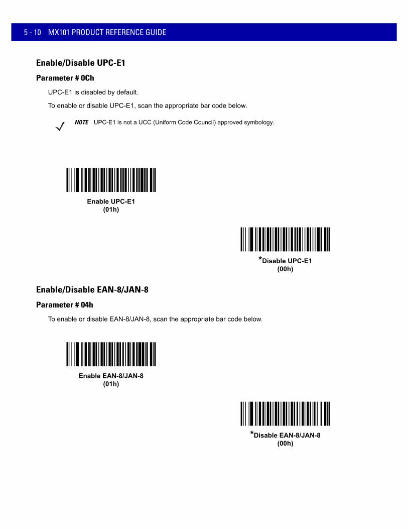
Enable/Disable UPC-E1
Parameter # 0Ch
UPC-E1 is disabled by default.
To enable or disable UPC-E1, scan the appropriate bar code below.
Enable/Disable EAN-8/JAN-8
Parameter # 04h
To enable or disable EAN-8/JAN-8, scan the appropriate bar code below.
NOTE UPC-E1 is not a UCC (Uniform Code Council) approved symbology.
Enable UPC-E1(01h)
*Disable UPC-E1(00h)
Enable EAN-8/JAN-8(01h)
*Disable EAN-8/JAN-8(00h)

Symbologies 5 - 11
Enable/Disable EAN-13/JAN-13
Parameter # 03h
To enable or disable EAN-13/JAN-13, scan the appropriate bar code below.
Enable/Disable Bookland EAN
Parameter # 53h
To enable or disable Bookland EAN, scan the appropriate bar code below.
Enable EAN-13/JAN-13(01h)
*Disable EAN-13/JAN-13(00h)
Enable Bookland EAN (01h)
*Disable Bookland EAN(00h)
NOTE If Bookland EAN is enabled, select a Bookland ISBN Format on page 5-12. Also select either Decode UPC/EAN Supplementals, Autodiscriminate UPC/EAN Supplementals, or Enable 978/979 Supplemental Mode in Decode UPC/EAN/JAN Supplementals on page 5-13.

5 - 12 MX101 PRODUCT REFERENCE GUIDE
Bookland ISBN Format
Parameter # F1h 40h
If Bookland EAN is enabled, select one of the following formats for Bookland data:
• Bookland ISBN-10 - The scanner reports Bookland data starting with 978 in traditional 10-digit format with the special Bookland check digit for backward-compatibility. Data starting with 979 is not considered Bookland in this mode.
• Bookland ISBN-13 - The scanner reports Bookland data (starting with either 978 or 979) as EAN-13 in 13-digit format to meet the 2007 ISBN-13 protocol.
*Bookland ISBN-10(00h)
Bookland ISBN-13(01h)
NOTE For Bookland EAN to function properly, ensure Bookland EAN is enabled (see Enable/Disable Bookland EAN on page 5-11), then select either Decode UPC/EAN Supplementals, Autodiscriminate UPC/EAN Supplementals, or Enable 978/979 Supplemental Mode in Decode UPC/EAN/JAN Supplementals on page 5-13.
Symbologies 5 - 13
Decode UPC/EAN/JAN Supplementals
Parameter # 10h
Supplementals are bar codes appended according to specific format conventions (e.g., UPC A+2, UPC E+2, EAN 13+2). The following options are available:
• If you select Ignore UPC/EAN with Supplementals, and the scanner is presented with a UPC/EAN plus supplemental symbol, the scanner decodes UPC/EAN and ignores the supplemental characters.
• If you select Decode UPC/EAN with Supplementals, the scanner only decodes UPC/EAN symbols with supplemental characters, and ignores symbols without supplementals.
• If you select Autodiscriminate UPC/EAN Supplementals, the scanner decodes UPC/EAN symbols with supplemental characters immediately. If the symbol does not have a supplemental, the scanner must decode the bar code the number of times set via UPC/EAN/JAN Supplemental Redundancy on page 5-16 before transmitting its data to confirm that there is no supplemental.
• If you select one of the following Supplemental Mode options, the scanner immediately transmits EAN-13 bar codes starting with that prefix that have supplemental characters. If the symbol does not have a supplemental, the scanner must decode the bar code the number of times set via UPC/EAN/JAN Supplemental Redundancy on page 5-16 before transmitting its data to confirm that there is no supplemental. The scanner transmits UPC/EAN bar codes that do not have that prefix immediately.
• Enable 378/379 Supplemental Mode
• Enable 978/979 Supplemental Mode
• Enable 977 Supplemental Mode
• Enable 414/419/434/439 Supplemental Mode
• Enable 491 Supplemental Mode
• Enable Smart Supplemental Mode - applies to EAN-13 bar codes starting with any prefix listed previously.
• Supplemental User-Programmable Type 1 - applies to EAN-13 bar codes starting with a 3-digit user-defined prefix. Set this 3-digit prefix using User-Programmable Supplementals on page 5-16.
• Supplemental User-Programmable Type 1 and 2 - applies to EAN-13 bar codes starting with either of two 3-digit user-defined prefixes. Set the 3-digit prefixes using User-Programmable Supplementals on page 5-16.
• Smart Supplemental Plus User-Programmable 1 - applies to EAN-13 bar codes starting with any prefix listed previously or the user-defined prefix set using User-Programmable Supplementals on page 5-16.
• Smart Supplemental Plus User-Programmable 1 and 2 - applies to EAN-13 bar codes starting with any prefix listed previously or one of the two user-defined prefixes set using User-Programmable Supplementals on page 5-16.
NOTE If you select 978/979 Supplemental Mode and are scanning Bookland EAN bar codes, see Enable/Disable Bookland EAN on page 5-11 to enable Bookland EAN, and select a format using Bookland ISBN Format on page 5-12.
NOTE To minimize the risk of invalid data transmission, select either to decode or ignore supplemental characters.

5 - 14 MX101 PRODUCT REFERENCE GUIDE
Decode UPC/EAN/JAN Supplementals (continued)
Decode UPC/EAN/JAN Only With Supplementals(01h)
*Ignore Supplementals(00h)
Autodiscriminate UPC/EAN/JAN Supplementals(02h)
Enable 378/379 Supplemental Mode(04h)
Enable 978/979 Supplemental Mode(05h)
Enable 977 Supplemental Mode(07h)

Symbologies 5 - 15
Decode UPC/EAN/JAN Supplementals (continued)
Enable 414/419/434/439 Supplemental Mode(06h)
Enable 491 Supplemental Mode(08h)
Enable Smart Supplemental Mode(03h)
Supplemental User-Programmable Type 1(09h)
Supplemental User-Programmable Type 1 and 2(0Ah)
Smart Supplemental Plus User-Programmable 1(0Bh)
Smart Supplemental Plus User-Programmable 1 and 2(0Ch)

5 - 16 MX101 PRODUCT REFERENCE GUIDE
User-Programmable Supplementals
Supplemental 1: Parameter # F1h 43h
Supplemental 2: Parameter # F1h 44h
If you selected a Supplemental User-Programmable option from Decode UPC/EAN/JAN Supplementals on page 5-13, select User-Programmable Supplemental 1 to set the 3-digit prefix. Then select the 3 digits using the numeric bar codes beginning on page D-1. Select User-Programmable Supplemental 2 to set a second 3-digit prefix. Then select the 3 digits using the numeric bar codes beginning on page D-1.
UPC/EAN/JAN Supplemental Redundancy
Parameter # 50h
If you selected Autodiscriminate UPC/EAN/JAN Supplementals, this option adjusts the number of times to decode a symbol without supplementals before transmission. The range is from two to thirty times. Five or above is recommended when decoding a mix of UPC/EAN/JAN symbols with and without supplementals. The default is 10.
Scan the bar code below to set a decode redundancy value. Next, scan two numeric bar codes in Appendix D, Numeric Bar Codes. Enter a leading zero for single digit numbers. To correct an error or change a selection, scan Cancel on page D-2.
User-Programmable Supplemental 1
User-Programmable Supplemental 2
UPC/EAN/JAN Supplemental Redundancy

Symbologies 5 - 17
UPC/EAN/JAN Supplemental AIM ID Format
Parameter # F1h A0h
Select an output format when reporting UPC/EAN/JAN bar codes with Supplementals with Transmit Code ID Character on page 4-20 set to AIM Code ID Character:
• Separate - transmit UPC/EAN with supplementals with separate AIM IDs but one transmission, i.e.:
]E<0 or 4><data>]E<1 or 2>[supplemental data]
• Combined – transmit UPC/EAN with supplementals with one AIM ID and one transmission, i.e.:
]E3<data+supplemental data>
• Separate Transmissions - transmit UPC/EAN with supplementals with separate AIM IDs and separate transmissions, i.e.:
]E<0 or 4><data>]E<1 or 2>[supplemental data]
Separate(00h)
*Combined(01h)
Separate Transmissions(02h)

5 - 18 MX101 PRODUCT REFERENCE GUIDE
Transmit UPC-A Check Digit
Parameter # 28h
The check digit is the last character of the symbol used to verify the integrity of the data. Scan the appropriate bar code below to transmit the bar code data with or without the UPC-A check digit. It is always verified to guarantee the integrity of the data.
Transmit UPC-E Check Digit
Parameter # 29h
The check digit is the last character of the symbol used to verify the integrity of the data. Scan the appropriate bar code below to transmit the bar code data with or without the UPC-E check digit. It is always verified to guarantee the integrity of the data.
*Transmit UPC-A Check Digit(01h)
Do Not Transmit UPC-A Check Digit(00h)
*Transmit UPC-E Check Digit(01h)
Do Not Transmit UPC-E Check Digit(00h)

Symbologies 5 - 19
Transmit UPC-E1 Check Digit
Parameter # 2Ah
The check digit is the last character of the symbol used to verify the integrity of the data. Scan the appropriate bar code below to transmit the bar code data with or without the UPC-E1 check digit. It is always verified to guarantee the integrity of the data.
UPC-A Preamble
Parameter # 22h
Preamble characters are part of the UPC symbol, and include Country Code and System Character. There are three options for transmitting a UPC-A preamble to the host device: transmit System Character only, transmit System Character and Country Code (“0” for USA), and transmit no preamble. Select the appropriate option to match the host system.
*Transmit UPC-E1 Check Digit(01h)
Do Not Transmit UPC-E1 Check Digit(00h)
No Preamble (<DATA>)(00h)
*System Character (<SYSTEM CHARACTER> <DATA>)
(01h)
System Character & Country Code(< COUNTRY CODE> <SYSTEM CHARACTER> <DATA>)
(02h)

5 - 20 MX101 PRODUCT REFERENCE GUIDE
UPC-E Preamble
Parameter # 23h
Preamble characters are part of the UPC symbol, and include Country Code and System Character. There are three options for transmitting a UPC-E preamble to the host device: transmit System Character only, transmit System Character and Country Code (“0” for USA), and transmit no preamble. Select the appropriate option to match the host system.
No Preamble (<DATA>)(00h)
*System Character (<SYSTEM CHARACTER> <DATA>)
(01h)
System Character & Country Code(< COUNTRY CODE> <SYSTEM CHARACTER> <DATA>)
(02h)

Symbologies 5 - 21
UPC-E1 Preamble
Parameter # 24h
Preamble characters are part of the UPC symbol, and include Country Code and System Character. There are three options for transmitting a UPC-E1 preamble to the host device: transmit System Character only, transmit System Character and Country Code (“0” for USA), and transmit no preamble. Select the appropriate option to match the host system.
No Preamble (<DATA>)(00h)
*System Character (<SYSTEM CHARACTER> <DATA>)
(01h)
System Character & Country Code(< COUNTRY CODE> <SYSTEM CHARACTER> <DATA>)
(02h)

5 - 22 MX101 PRODUCT REFERENCE GUIDE
Convert UPC-E to UPC-A
Parameter # 25h
Enable this to convert UPC-E (zero suppressed) decoded data to UPC-A format before transmission. After conversion, the data follows UPC-A format and is affected by UPC-A programming selections (e.g., Preamble, Check Digit).
Disable this to transmit UPC-E decoded data as UPC-E data, without conversion.
Convert UPC-E1 to UPC-A
Parameter # 26h
Enable this to convert UPC-E1 decoded data to UPC-A format before transmission. After conversion, the data follows UPC-A format and is affected by UPC-A programming selections (e.g., Preamble, Check Digit).
Disable this to transmit UPC-E1 decoded data as UPC-E1 data, without conversion.
Convert UPC-E to UPC-A (Enable)(01h)
*Do Not Convert UPC-E to UPC-A (Disable)(00h)
Convert UPC-E1 to UPC-A (Enable)(01h)
*Do Not Convert UPC-E1 to UPC-A (Disable)(00h)

Symbologies 5 - 23
EAN-8/JAN-8 Extend
Parameter # 27h
Enable this parameter to add five leading zeros to decoded EAN-8 symbols to make them compatible in format to EAN-13 symbols.
Disable this to transmit EAN-8 symbols as is.
UCC Coupon Extended Code
Parameter # 55h
Enable this parameter to decode UPC-A bar codes starting with digit ‘5’, EAN-13 bar codes starting with digit ‘99’, and UPC-A/GS1-128 Coupon Codes. UPCA, EAN-13, and GS1-128 must be enabled to scan all types of Coupon Codes.
Enable EAN/JAN Zero Extend(01h)
*Disable EAN/JAN Zero Extend(00h)
Enable UCC Coupon Extended Code(01h)
*Disable UCC Coupon Extended Code(00h)
NOTE See UPC/EAN/JAN Supplemental Redundancy on page 5-16 to control autodiscrimination of the GS1-128 (right half) of a coupon code.

5 - 24 MX101 PRODUCT REFERENCE GUIDE
Coupon Report
Parameter # F1h DAh
Traditional coupon symbols (old coupon symbols) are composed of two bar codes: UPC/EAN and Code128. A new coupon symbol is composed of a single Databar Expanded bar code. The new coupon format offers more options for purchase values (up to $999.99) and supports complex discount offers such as a second purchase requirement.
An interim coupon symbol also exists that contains both types of bar codes: UPC/EAN and Databar Expanded. This format accommodates both retailers that do not recognize or use the additional information included in the new coupon symbol, as well as those who can process new coupon symbols.
Scan a bar code below to select one of the following options for decoding coupon symbols:
• Old Coupon Symbols - Scanning an old coupon symbol reports both UPC and Code 128, scanning an interim coupon symbol reports UPC, and scanning a new coupon symbol reports nothing (no decode).
• New Coupon Symbols - Scanning an old coupon symbol reports either UPC or Code 128, and scanning an interim coupon symbol or a new coupon symbol reports Databar Expanded.
• Both Coupon Formats - Scanning an old coupon symbol reports both UPC and Code 128, and scanning an interim coupon symbol or a new coupon symbol reports Databar Expanded.
Old Coupon Symbols(00h)
*New Coupon Symbols(01h)
Both Coupon Formats(02h)

Symbologies 5 - 25
ISSN EAN
Parameter # F1h 69h
To enable or disable ISSN EAN, scan the appropriate bar code below.
Enable ISSN EAN (01h)
*Disable ISSN EAN (00h)

5 - 26 MX101 PRODUCT REFERENCE GUIDE
Code 128
Enable/Disable Code 128
Parameter # 08h
To enable or disable Code 128, scan the appropriate bar code below.
Set Lengths for Code 128
Parameter # L1 = D1h, L2 = D2h
The length of a code refers to the number of characters (i.e., human readable characters), including check digit(s) the code contains. Set lengths for Code 128 to any length, one or two discrete lengths, or lengths within a specific range.
• One Discrete Length - Select this option to decode only Code 128 symbols containing a selected length. Select the length using the numeric bar codes in Appendix D, Numeric Bar Codes. For example, to decode only Code 128 symbols with 14 characters, scan Code 128 - One Discrete Length, then scan 1 followed by 4. To correct an error or change the selection, scan Cancel on page D-2.
• Two Discrete Lengths - Select this option to decode only Code 128 symbols containing either of two selected lengths. Select lengths using the numeric bar codes in Appendix D, Numeric Bar Codes. For example, to decode only Code 128 symbols containing either 2 or 14 characters, select Code 128 - Two Discrete Lengths, then scan 0, 2, 1, and then 4. To correct an error or change the selection, scan Cancel on page D-2.
• Length Within Range - Select this option to decode a Code 128 symbol with a specific length range. Select lengths using numeric bar codes in Appendix D, Numeric Bar Codes. For example, to decode Code 128 symbols containing between 4 and 12 characters, first scan Code 128 - Length Within Range. Then scan 0, 4, 1, and 2 (enter a leading zero for single digit numbers). To correct an error or change the selection, scan Cancel on page D-2.
• Any Length - Select this option to decode Code 128 symbols containing any number of characters within the scanner’s capability.
*Enable Code 128(01h)
Disable Code 128(00h)
NOTE When setting lengths for different bar code types, enter a leading zero for single digit numbers.

Symbologies 5 - 27
Set Lengths for Code 128 (continued)
Enable/Disable GS1-128 (formerly UCC/EAN-128)
Parameter # 0Eh
To enable or disable GS1-128, scan the appropriate bar code below.
Code 128 - One Discrete Length
Code 128 - Two Discrete Lengths
Code 128 - Length Within Range
*Code 128 - Any Length
Enable GS1-128(01h)
*Disable GS1-128(00h)

5 - 28 MX101 PRODUCT REFERENCE GUIDE
Enable/Disable ISBT 128
Parameter # 54h
ISBT 128 is a variant of Code 128 used in the blood bank industry. Scan a bar code below to enable or disable ISBT 128. If necessary, the host must perform concatenation of the ISBT data.
Enable ISBT 128(01h)
*Disable ISBT 128(00h)

Symbologies 5 - 29
ISBT Concatenation
Parameter # F1h 41h
Select an option for concatenating pairs of ISBT code types:
• If you select Disable ISBT Concatenation, the scanner does not concatenate pairs of ISBT codes it encounters.
• If you select Enable ISBT Concatenation, there must be two ISBT codes in order for the scanner to decode and perform concatenation. The scanner does not decode single ISBT symbols.
• If you select Autodiscriminate ISBT Concatenation, the scanner decodes and concatenates pairs of ISBT codes immediately. If only a single ISBT symbol is present, the scanner must decode the symbol the number of times set via ISBT Concatenation Redundancy on page 5-30 before transmitting its data to confirm that there is no additional ISBT symbol.
*Disable ISBT Concatenation(00h)
Enable ISBT Concatenation(01h)
Autodiscriminate ISBT Concatenation(02h)

5 - 30 MX101 PRODUCT REFERENCE GUIDE
Check ISBT Table
Parameter # F1h 42h
The ISBT specification includes a table that lists several types of ISBT bar codes that are commonly used in pairs. If you set ISBT Concatenation to Enable, enable Check ISBT Table to concatenate only those pairs found in this table. Other types of ISBT codes are not concatenated.
ISBT Concatenation Redundancy
Parameter # DFh
If you set ISBT Concatenation to Autodiscriminate, use this parameter to set the number of times the scanner must decode an ISBT symbol before determining that there is no additional symbol.
Scan the bar code below, then scan two numeric bar codes in Appendix D, Numeric Bar Codes to set a value between 2 and 20. Enter a leading zero for single digit numbers. To correct an error or change a selection, scan Cancel on page D-2. The default is 10.
*Enable Check ISBT Table(01h)
Disable Check ISBT Table(00h)
ISBT Concatenation Redundancy

Symbologies 5 - 31
Code 39
Enable/Disable Code 39
Parameter # 00h
To enable or disable Code 39, scan the appropriate bar code below.
Enable/Disable Trioptic Code 39
Parameter # 0Dh
Trioptic Code 39 is a variant of Code 39 used in the marking of computer tape cartridges. Trioptic Code 39 symbols always contain six characters. To enable or disable Trioptic Code 39, scan the appropriate bar code below.
Enable Code 39(01h)
* Disable Code 39(00h)
Enable Trioptic Code 39(01h)
*Disable Trioptic Code 39(00h)
NOTE You cannot enable Trioptic Code 39 and Code 39 Full ASCII simultaneously.

5 - 32 MX101 PRODUCT REFERENCE GUIDE
Convert Code 39 to Code 32
Parameter # 56h
Code 32 is a variant of Code 39 used by the Italian pharmaceutical industry. Scan the appropriate bar code below to enable or disable converting Code 39 to Code 32.
Code 32 Prefix
Parameter # E7h
Scan the appropriate bar code below to enable or disable adding the prefix character “A” to all Code 32 bar codes.
NOTE Code 39 must be enabled for this parameter to function.
Enable Convert Code 39 to Code 32(01h)
*Disable Convert Code 39 to Code 32(00h)
NOTE Convert Code 39 to Code 32 must be enabled for this parameter to function.
Enable Code 32 Prefix(01h)
*Disable Code 32 Prefix(00h)

Symbologies 5 - 33
Set Lengths for Code 39
Parameter # L1 = 12h, L2 = 13h
The length of a code refers to the number of characters (i.e., human readable characters), including check digit(s) the code contains. Set lengths for Code 39 to any length, one or two discrete lengths, or lengths within a specific range. If Code 39 Full ASCII is enabled, Length Within a Range or Any Length are the preferred options.
• One Discrete Length - Select this option to decode only Code 39 symbols containing a selected length. Select the length using the numeric bar codes in Appendix D, Numeric Bar Codes. For example, to decode only Code 39 symbols with 14 characters, scan Code 39 - One Discrete Length, then scan 1 followed by 4. To correct an error or change the selection, scan Cancel on page D-2.
• Two Discrete Lengths - Select this option to decode only Code 39 symbols containing either of two selected lengths. Select lengths using the numeric bar codes in Appendix D, Numeric Bar Codes. For example, to decode only Code 39 symbols containing either 2 or 14 characters, select Code 39 - Two Discrete Lengths, then scan 0, 2, 1, and then 4. To correct an error or change the selection, scan Cancel on page D-2.
• Length Within Range - Select this option to decode a Code 39 symbol with a specific length range. Select lengths using numeric bar codes in Appendix D, Numeric Bar Codes. For example, to decode Code 39 symbols containing between 4 and 12 characters, first scan Code 39 - Length Within Range. Then scan 0, 4, 1, and 2 (enter a leading zero for single digit numbers). To correct an error or change the selection, scan Cancel on page D-2.
• Any Length - Select this option to decode Code 39 symbols containing any number of characters within the scanner’s capability.
NOTE When setting lengths for different bar code types, enter a leading zero for single digit numbers.
Code 39 - One Discrete Length
Code 39 - Two Discrete Lengths
*Code 39 - Length Within Range
Code 39 - Any Length

5 - 34 MX101 PRODUCT REFERENCE GUIDE
Code 39 Check Digit Verification
Parameter # 30h
Enable this feature to check the integrity of all Code 39 symbols to verify that the data complies with specified check digit algorithm. Only Code 39 symbols which include a modulo 43 check digit are decoded. Enable this feature if the Code 39 symbols contain a Modulo 43 check digit.
Transmit Code 39 Check Digit
Parameter # 2Bh
Scan a bar code below to transmit Code 39 data with or without the check digit.
Enable Code 39 Check Digit(01h)
*Disable Code 39 Check Digit (00h)
Transmit Code 39 Check Digit (Enable)(01h)
*Do Not Transmit Code 39 Check Digit (Disable)(00h)
NOTE Code 39 Check Digit Verification must be enabled for this parameter to function.
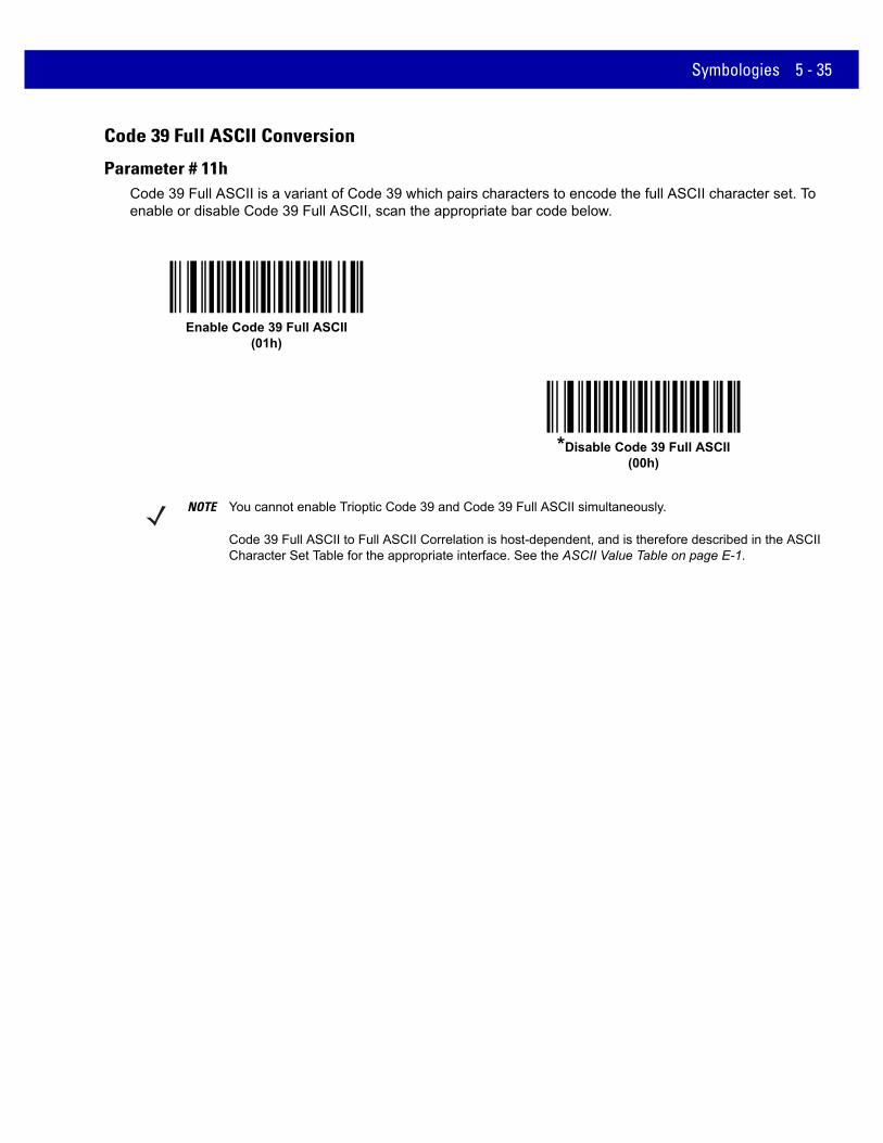
Symbologies 5 - 35
Code 39 Full ASCII Conversion
Parameter # 11hCode 39 Full ASCII is a variant of Code 39 which pairs characters to encode the full ASCII character set. To enable or disable Code 39 Full ASCII, scan the appropriate bar code below.
Enable Code 39 Full ASCII(01h)
*Disable Code 39 Full ASCII(00h)
NOTE You cannot enable Trioptic Code 39 and Code 39 Full ASCII simultaneously.
Code 39 Full ASCII to Full ASCII Correlation is host-dependent, and is therefore described in the ASCII Character Set Table for the appropriate interface. See the ASCII Value Table on page E-1.

5 - 36 MX101 PRODUCT REFERENCE GUIDE
Code 39 Buffering - Scan & Store
Parameter # 71h
This feature allows the scanner to accumulate data from multiple Code 39 symbols.
Selecting the Scan and Store option (Buffer Code 39) temporarily buffers all Code 39 symbols having a leading space as a first character for later transmission. The leading space is not buffered.
Decoding a Code 39 symbol with no leading space transmits in sequence all buffered data in a first-in first-out format, plus the “triggering” symbol. See the following pages for further details.
Select Do Not Buffer Code 39 to transmit all decoded Code 39 symbols immediately without storing them in the buffer.
This feature affects Code 39 only. If selecting Buffer Code 39, we recommend configuring the scanner to decode Code 39 symbology only.
While there is data in the transmission buffer, you cannot select Do Not Buffer Code 39. The buffer holds 200 bytes of information.
To disable Code 39 buffering when there is data in the transmission buffer, first force the buffer transmission (see Transmit Buffer on page 5-37) or clear the buffer.
Buffer Data
To buffer data, enable Code 39 buffering and scan a Code 39 symbol with a space immediately following the start pattern.
• Unless the data overflows the transmission buffer, the scanner issues a low/high beep to indicate successful decode and buffering. (For overflow conditions, see Overfilling Transmission Buffer on page 5-37.)
• The scanner adds the decoded data excluding the leading space to the transmission buffer.
• No transmission occurs.
Clear Transmission Buffer
To clear the transmission buffer, scan the Clear Buffer bar code below, which contains only a start character, a dash (minus), and a stop character.
• The scanner issues a short high/low/high beep.
• The scanner erases the transmission buffer.
• No transmission occurs.
Buffer Code 39 (Enable)(01h)
*Do Not Buffer Code 39 (Disable)(00h)
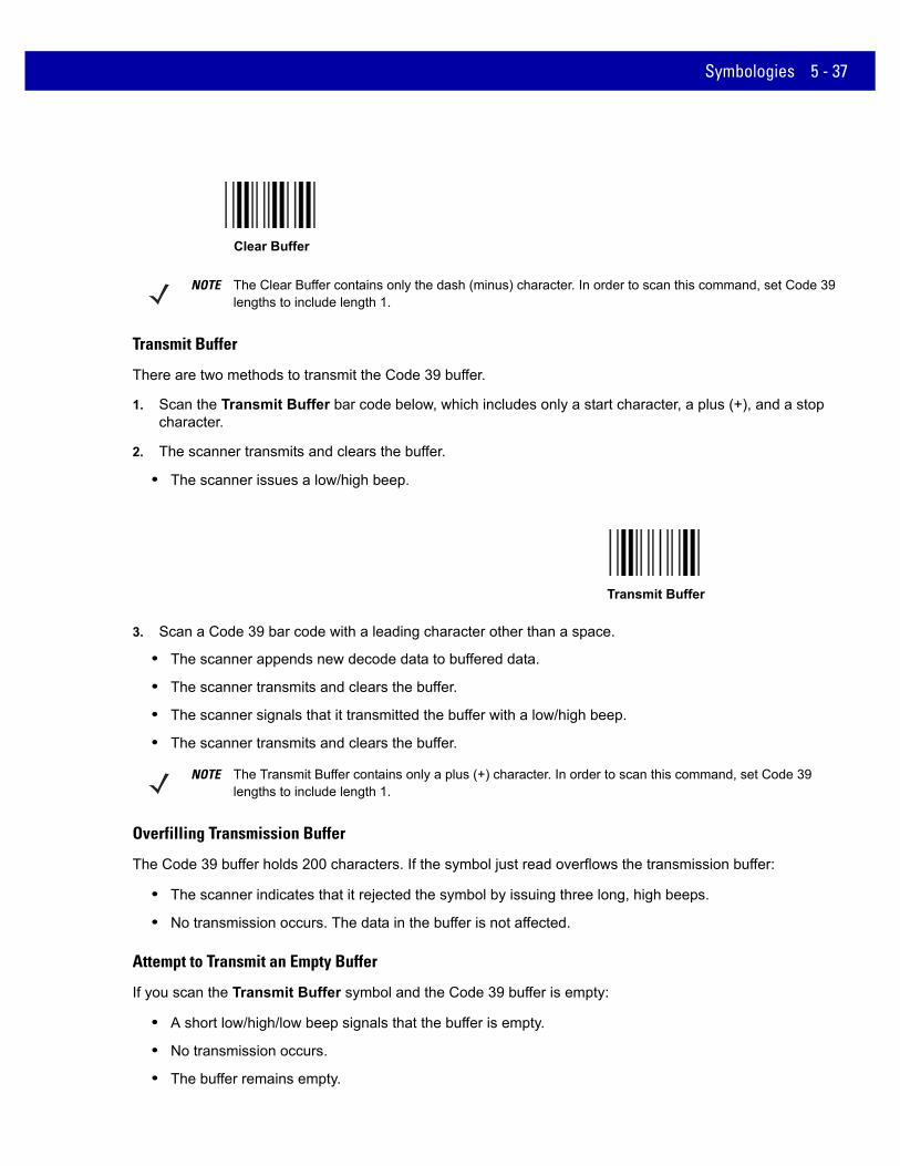
Symbologies 5 - 37
Transmit Buffer
There are two methods to transmit the Code 39 buffer.
1. Scan the Transmit Buffer bar code below, which includes only a start character, a plus (+), and a stop character.
2. The scanner transmits and clears the buffer.
• The scanner issues a low/high beep.
3. Scan a Code 39 bar code with a leading character other than a space.
• The scanner appends new decode data to buffered data.
• The scanner transmits and clears the buffer.
• The scanner signals that it transmitted the buffer with a low/high beep.
• The scanner transmits and clears the buffer.
Overfilling Transmission Buffer
The Code 39 buffer holds 200 characters. If the symbol just read overflows the transmission buffer:
• The scanner indicates that it rejected the symbol by issuing three long, high beeps.
• No transmission occurs. The data in the buffer is not affected.
Attempt to Transmit an Empty Buffer
If you scan the Transmit Buffer symbol and the Code 39 buffer is empty:
• A short low/high/low beep signals that the buffer is empty.
• No transmission occurs.
• The buffer remains empty.
Clear Buffer
NOTE The Clear Buffer contains only the dash (minus) character. In order to scan this command, set Code 39 lengths to include length 1.
Transmit Buffer
NOTE The Transmit Buffer contains only a plus (+) character. In order to scan this command, set Code 39 lengths to include length 1.

5 - 38 MX101 PRODUCT REFERENCE GUIDE
Code 93
Enable/Disable Code 93
Parameter # 09h
To enable or disable Code 93, scan the appropriate bar code below.
Set Lengths for Code 93
Parameter # L1 = 1Ah, L2 = 1Bh
The length of a code refers to the number of characters (i.e., human readable characters), including check digit(s) the code contains. Set lengths for Code 93 to any length, one or two discrete lengths, or lengths within a specific range.
• One Discrete Length - Select this option to decode only Code 93 symbols containing a selected length. Select the length using the numeric bar codes in Appendix D, Numeric Bar Codes. For example, to decode only Code 93 symbols with 14 characters, scan Code 93 - One Discrete Length, then scan 1 followed by 4. To correct an error or to change the selection, scan Cancel on page D-2.
• Two Discrete Lengths - Select this option to decode only Code 93 symbols containing either of two selected lengths. Select lengths using the numeric bar codes in Appendix D, Numeric Bar Codes. For example, to decode only Code 93 symbols containing either 2 or 14 characters, select Code 93 - Two Discrete Lengths, then scan 0, 2, 1, and then 4. To correct an error or to change the selection, scan Cancel on page D-2.
• Length Within Range - Select this option to decode a Code 93 symbol with a specific length range. Select lengths using the numeric bar codes in Appendix D, Numeric Bar Codes. For example, to decode Code 93 symbols containing between 4 and 12 characters, first scan Code 93 - Length Within Range. Then scan 0, 4, 1, and 2 (enter a leading zero for single digit numbers). To correct an error or change the selection, scan Cancel on page D-2.
• Any Length - Scan this option to decode Code 93 symbols containing any number of characters within the scanner’s capability.
Enable Code 93(01h)
*Disable Code 93(00h)

Symbologies 5 - 39
Set Lengths for Code 93 (continued)
Code 93 - One Discrete Length
Code 93 - Two Discrete Lengths
*Code 93 - Length Within Range
Code 93 - Any Length

5 - 40 MX101 PRODUCT REFERENCE GUIDE
Code 11
Code 11
Parameter # 0Ah
To enable or disable Code 11, scan the appropriate bar code below.
Set Lengths for Code 11
Parameter # L1 = 1Ch, L2 = 1Dh
The length of a code refers to the number of characters (i.e., human readable characters), including check digit(s) the code contains. Set lengths for Code 11 to any length, one or two discrete lengths, or lengths within a specific range.
• One Discrete Length - Select this option to decode only Code 11 symbols containing a selected length. Select the length using the numeric bar codes in Appendix D, Numeric Bar Codes. For example, to decode only Code 11 symbols with 14 characters, scan Code 11 - One Discrete Length, then scan 1 followed by 4. To correct an error or to change the selection, scan Cancel on page D-2.
• Two Discrete Lengths - Select this option to decode only Code 11 symbols containing either of two selected lengths. Select lengths using the numeric bar codes in Appendix D, Numeric Bar Codes. For example, to decode only Code 11 symbols containing either 2 or 14 characters, select Code 11 - Two Discrete Lengths, then scan 0, 2, 1, and then 4. To correct an error or to change the selection, scan Cancel on page D-2.
• Length Within Range - Select this option to decode a Code 11 symbol with a specific length range. Select lengths using numeric bar codes in Appendix D, Numeric Bar Codes. For example, to decode Code 11 symbols containing between 4 and 12 characters, first scan Code 11 - Length Within Range. Then scan 0, 4, 1, and 2 (enter a leading zero for single digit numbers). To correct an error or change the selection, scan Cancel on page D-2.
• Any Length - Scan this option to decode Code 11 symbols containing any number of characters within the scanner’s capability.
Enable Code 11(01h)
*Disable Code 11(00h)

Symbologies 5 - 41
Set Lengths for Code 11 (continued)
Code 11 - One Discrete Length
Code 11 - Two Discrete Lengths
*Code 11 - Length Within Range
Code 11 - Any Length

5 - 42 MX101 PRODUCT REFERENCE GUIDE
Code 11 Check Digit Verification
Parameter # 34hThis feature allows the scanner to check the integrity of all Code 11 symbols to verify that the data complies with the specified check digit algorithm. This selects the check digit mechanism for the decoded Code 11 bar code. The options are to check for one check digit, check for two check digits, or disable the feature.
To enable this feature, scan the bar code below corresponding to the number of check digits encoded in the Code 11 symbols.
*Disable(00h)
One Check Digit(01h)
Two Check Digits(02h)

Symbologies 5 - 43
Transmit Code 11 Check Digits
Parameter # 2FhThis feature selects whether or not to transmit the Code 11 check digit(s).
Transmit Code 11 Check Digit(s) (Enable)(01h)
*Do Not Transmit Code 11 Check Digit(s) (Disable)(00h)
NOTE Code 11 Check Digit Verification must be enabled for this parameter to function.

5 - 44 MX101 PRODUCT REFERENCE GUIDE
Interleaved 2 of 5 (ITF)
Enable/Disable Interleaved 2 of 5
Parameter # 06h
To enable or disable Interleaved 2 of 5, scan the appropriate bar code below, and select an Interleaved 2 of 5 length from the following pages.
Set Lengths for Interleaved 2 of 5
Parameter # L1 = 16h, L2 = 17h
The length of a code refers to the number of characters (i.e., human readable characters), including check digit(s) the code contains. Set lengths for I 2 of 5 to any length, one or two discrete lengths, or lengths within a specific range. The range for Interleaved 2 of 5 lengths is 0 - 55.
• One Discrete Length - Select this option to decode only I 2 of 5 symbols containing a selected length. Select the length using the numeric bar codes in Appendix D, Numeric Bar Codes. For example, to decode only I 2 of 5 symbols with 14 characters, scan I 2 of 5 - One Discrete Length, then scan 1 followed by 4. To correct an error or to change the selection, scan Cancel on page D-2.
• Two Discrete Lengths - Select this option to decode only I 2 of 5 symbols containing either of two selected lengths. Select lengths using the numeric bar codes in Appendix D, Numeric Bar Codes. For example, to decode only I 2 of 5 symbols containing either 2 or 14 characters, select I 2 of 5 - Two Discrete Lengths, then scan 0, 2, 1, and then 4. To correct an error or to change the selection, scan Cancel on page D-2.
• Length Within Range - Select this option to decode an I 2 of 5 symbol with a specific length range. Select lengths using numeric bar codes in Appendix D, Numeric Bar Codes. For example, to decode I 2 of 5 symbols containing between 4 and 12 characters, first scan I 2 of 5 - Length Within Range. Then scan 0, 4, 1, and 2 (enter a leading zero for single digit numbers). To correct an error or change the selection, scan Cancel on page D-2.
• Any Length - Scan this option to decode I 2 of 5 symbols containing any number of characters within the scanner’s capability.
Enable Interleaved 2 of 5(01h)
*Disable Interleaved 2 of 5(00h)
NOTE Due to the construction of the I 2 of 5 symbology, it is possible for a scan line covering only a portion of the code to transmit as a complete scan, yielding less data than is encoded in the bar code. To prevent this, select specific lengths (I 2 of 5 - One Discrete Length, Two Discrete Lengths) for I 2 of 5 applications.

Symbologies 5 - 45
Set Lengths for Interleaved 2 of 5 (continued)
*I 2 of 5 - One Discrete Length
I 2 of 5 - Two Discrete Lengths
I 2 of 5 - Length Within Range
I 2 of 5 - Any Length

5 - 46 MX101 PRODUCT REFERENCE GUIDE
I 2 of 5 Check Digit Verification
Parameter # 31h
Enable this feature to check the integrity of all I 2 of 5 symbols to verify the data complies with either the specified Uniform Symbology Specification (USS), or the Optical Product Code Council (OPCC) check digit algorithm.
Transmit I 2 of 5 Check Digit
Parameter # 2Ch
Scan the appropriate bar code below to transmit I 2 of 5 data with or without the check digit.
*Disable(00h)
USS Check Digit (01h)
OPCC Check Digit (02h)
Transmit I 2 of 5 Check Digit (Enable)(01h)
*Do Not Transmit I 2 of 5 Check Digit (Disable)(00h)

Symbologies 5 - 47
Convert I 2 of 5 to EAN-13
Parameter # 52h
Enable this parameter to convert 14-character I 2 of 5 codes to EAN-13, and transmit to the host as EAN-13. To accomplish this, the I 2 of 5 code must be enabled, and the code must have a leading zero and a valid EAN-13 check digit.
Convert I 2 of 5 to EAN-13 (Enable)(01h)
*Do Not Convert I 2 of 5 to EAN-13 (Disable)(00h)

5 - 48 MX101 PRODUCT REFERENCE GUIDE
Discrete 2 of 5 (DTF)
Enable/Disable Discrete 2 of 5
Parameter # 05h
To enable or disable Discrete 2 of 5, scan the appropriate bar code below.
Set Lengths for Discrete 2 of 5
Parameter # L1 = 14h, L2 = 15h
The length of a code refers to the number of characters (i.e., human readable characters), including check digit(s) the code contains. Set lengths for D 2 of 5 to any length, one or two discrete lengths, or lengths within a specific range. The range for Discrete 2 of 5 lengths is 0 - 55.
• One Discrete Length - Select this option to decode only D 2 of 5 symbols containing a selected length. Select the length using the numeric bar codes in Appendix D, Numeric Bar Codes. For example, to decode only D 2 of 5 symbols with 14 characters, scan D 2 of 5 - One Discrete Length, then scan 1 followed by 4. To correct an error or to change the selection, scan Cancel on page D-2.
• Two Discrete Lengths - Select this option to decode only D 2 of 5 symbols containing either of two selected lengths. Select lengths using the numeric bar codes in Appendix D, Numeric Bar Codes. For example, to decode only D 2 of 5 symbols containing either 2 or 14 characters, select D 2 of 5 - Two Discrete Lengths, then scan 0, 2, 1, and then 4. To correct an error or to change the selection, scan Cancel on page D-2.
• Length Within Range - Select this option to decode a D 2 of 5 symbol with a specific length range. Select lengths using numeric bar codes in Appendix D, Numeric Bar Codes. For example, to decode D 2 of 5 symbols containing between 4 and 12 characters, first scan D 2 of 5 - Length Within Range. Then scan 0, 4, 1, and 2 (enter a leading zero for single digit numbers). To correct an error or change the selection, scan Cancel on page D-2.
• Any Length - Scan this option to decode D 2 of 5 symbols containing any number of characters within the scanner’s capability.
Enable Discrete 2 of 5(01h)
*Disable Discrete 2 of 5(00h)
NOTE Due to the construction of the D 2 of 5 symbology, it is possible for a scan line covering only a portion of the code to transmit as a complete scan, yielding less data than is encoded in the bar code. To prevent this, select specific lengths (D 2 of 5 - One Discrete Length, Two Discrete Lengths) for D 2 of 5 applications.

Symbologies 5 - 49
Set Lengths for Discrete 2 of 5 (continued)
*D 2 of 5 - One Discrete Length
D 2 of 5 - Two Discrete Lengths
D 2 of 5 - Length Within Range
D 2 of 5 - Any Length

5 - 50 MX101 PRODUCT REFERENCE GUIDE
Codabar (NW - 7)
Enable/Disable Codabar
Parameter # 07h
To enable or disable Codabar, scan the appropriate bar code below.
Set Lengths for Codabar
Parameter # L1 = 18h, L2 = 19h
The length of a code refers to the number of characters (i.e., human readable characters), including check digit(s) the code contains. Set lengths for Codabar to any length, one or two discrete lengths, or lengths within a specific range.
• One Discrete Length - Select this option to decode only Codabar symbols containing a selected length. Select the length using the numeric bar codes in Appendix D, Numeric Bar Codes. For example, to decode only Codabar symbols with 14 characters, scan Codabar - One Discrete Length, then scan 1 followed by 4. To correct an error or to change the selection, scan Cancel on page D-2.
• Two Discrete Lengths - Select this option to decode only Codabar symbols containing either of two selected lengths. Select lengths using the numeric bar codes in Appendix D, Numeric Bar Codes. For example, to decode only Codabar symbols containing either 2 or 14 characters, select Codabar - Two Discrete Lengths, then scan 0, 2, 1, and then 4. To correct an error or to change the selection, scan Cancel on page D-2.
• Length Within Range - Select this option to decode a Codabar symbol with a specific length range. Select lengths using numeric bar codes in Appendix D, Numeric Bar Codes. For example, to decode Codabar symbols containing between 4 and 12 characters, first scan Codabar - Length Within Range. Then scan 0, 4, 1, and 2 (enter a leading zero for single digit numbers). To correct an error or change the selection, scan Cancel on page D-2.
• Any Length - Scan this option to decode Codabar symbols containing any number of characters within the scanner’s capability.
Enable Codabar(01h)
*Disable Codabar(00h)

Symbologies 5 - 51
Set Lengths for Codabar (continued)
Codabar - One Discrete Length
Codabar - Two Discrete Lengths
*Codabar - Length Within Range
Codabar - Any Length

5 - 52 MX101 PRODUCT REFERENCE GUIDE
CLSI Editing
Parameter # 36h
Enable this parameter to strip the start and stop characters and insert a space after the first, fifth, and tenth characters of a 14-character Codabar symbol. Enable this feature if the host system requires this data format.
NOTIS Editing
Parameter # 37h
Enable this parameter to strip the start and stop characters from a decoded Codabar symbol. Enable this feature if the host system requires this data format.
NOTE Symbol length does not include start and stop characters.
Enable CLSI Editing(01h)
*Disable CLSI Editing(00h)
Enable NOTIS Editing(01h)
*Disable NOTIS Editing(00h)

Symbologies 5 - 53
Codabar Upper or Lower Case Start/Stop Characters Detection
Parameter # F2h 57h
Select whether to detect upper case or lower case Codabar start/stop characters.
Lower Case(01h)
*Upper Case(00h)

5 - 54 MX101 PRODUCT REFERENCE GUIDE
MSI
Enable/Disable MSI
Parameter # 0Bh
To enable or disable MSI, scan the appropriate bar code below.
Set Lengths for MSI
Parameter # L1 = 1Eh, L2 = 1Fh
The length of a code refers to the number of characters (i.e., human readable characters), including check digit(s) the code contains. Set lengths for MSI to any length, one or two discrete lengths, or lengths within a specific range.
• One Discrete Length - Select this option to decode only MSI symbols containing a selected length. Select the length using the numeric bar codes in Appendix D, Numeric Bar Codes. For example, to decode only MSI symbols with 14 characters, scan MSI - One Discrete Length, then scan 1 followed by 4. To correct an error or to change the selection, scan Cancel on page D-2.
• Two Discrete Lengths - Select this option to decode only MSI symbols containing either of two selected lengths. Select lengths using the numeric bar codes in Appendix D, Numeric Bar Codes. For example, to decode only MSI symbols containing either 2 or 14 characters, select MSI - Two Discrete Lengths, then scan 0, 2, 1, and then 4. To correct an error or to change the selection, scan Cancel on page D-2.
• Length Within Range - Select this option to decode a MSI symbol with a specific length range. Select lengths using numeric bar codes in Appendix D, Numeric Bar Codes. For example, to decode MSI symbols containing between 4 and 12 characters, first scan MSI - Length Within Range. Then scan 0, 4, 1, and 2 (enter a leading zero for single digit numbers). To correct an error or change the selection, scan Cancel on page D-2.
• Any Length - Scan this option to decode MSI symbols containing any number of characters within the scanner’s capability.
Enable MSI(01h)
*Disable MSI(00h)

Symbologies 5 - 55
Set Lengths for MSI (continued)
NOTE Due to the construction of the MSI symbology, it is possible for a scan line covering only a portion of the code to transmit as a complete scan, yielding less data than is encoded in the bar code. To prevent this, select specific lengths (MSI - One Discrete Length, Two Discrete Lengths) for MSI applications.
MSI - One Discrete Length
MSI - Two Discrete Lengths
*MSI - Length Within Range
MSI - Any Length

5 - 56 MX101 PRODUCT REFERENCE GUIDE
MSI Check Digits
Parameter # 32h
With MSI symbols, one check digit is mandatory and always verified by the reader. The second check digit is optional. If the MSI codes include two check digits, scan the Two MSI Check Digits bar code to enable verification of the second check digit.
See MSI Check Digit Algorithm on page 5-57 for the selection of second digit algorithms.
Transmit MSI Check Digit(s)
Parameter # 2Eh
Scan a bar code below to transmit MSI data with or without the check digit.
*One MSI Check Digit(00h)
Two MSI Check Digits(01h)
Transmit MSI Check Digit(s) (Enable)(01h)
*Do Not Transmit MSI Check Digit(s) (Disable)(00h)

Symbologies 5 - 57
MSI Check Digit Algorithm
Parameter # 33h
Two algorithms are possible for the verification of the second MSI check digit. Select the bar code below corresponding to the algorithm used to encode the check digit.
Chinese 2 of 5
Enable/Disable Chinese 2 of 5
Parameter # F0h 98h
To enable or disable Chinese 2 of 5, scan the appropriate bar code below.
MOD 10/MOD 11(00h)
*MOD 10/MOD 10(01h)
Enable Chinese 2 of 5(01h)
*Disable Chinese 2 of 5(00h)

5 - 58 MX101 PRODUCT REFERENCE GUIDE
Matrix 2 of 5
Enable/Disable Matrix 2 of 5
Parameter # F1h 6Ah
To enable or disable Matrix 2 of 5, scan the appropriate bar code below.
Enable Matrix 2 of 5 (01h)
*Disable Matrix 2 of 5 (00h)

Symbologies 5 - 59
Set Lengths for Matrix 2 of 5
Parameter # L1 = F1h 6Bh, L2 = F1h 6Ch
The length of a code refers to the number of characters (i.e., human readable characters), including check digit(s) the code contains. Set lengths for Matrix 2 of 5 to any length, one or two discrete lengths, or lengths within a specific range. The default is Any Length (set F1h 6Bh to 0).
• One Discrete Length - Select this option to decode only Matrix 2 of 5 symbols containing a selected length. Select the length using the numeric bar codes in Appendix D, Numeric Bar Codes. For example, to decode only Matrix 2 of 5 symbols with 14 characters, scan Matrix 2 of 5 - One Discrete Length, then scan 1 followed by 4. To correct an error or to change the selection, scan Cancel on page D-2.
• Two Discrete Lengths - Select this option to decode only Matrix 2 of 5 symbols containing either of two selected lengths. Select lengths using the numeric bar codes in Appendix D, Numeric Bar Codes. For example, to decode only Matrix 2 of 5 symbols containing either 2 or 14 characters, select Matrix 2 of 5 - Two Discrete Lengths, then scan 0, 2, 1, and then 4. To correct an error or to change the selection, scan Cancel on page D-2.
• Length Within Range - Select this option to decode a Matrix 2 of 5 symbol with a specific length range. Select lengths using the numeric bar codes in Appendix D, Numeric Bar Codes. For example, to decode Matrix 2 of 5 symbols containing between 4 and 12 characters, first scan Matrix 2 of 5 - Length Within Range. Then scan 0, 4, 1, and 2 (enter a leading zero for single digit numbers). To correct an error or change the selection, scan Cancel on page D-2.
• Any Length - Scan this option to decode Matrix 2 of 5 symbols containing any number of characters within the scanner’s capability.
Matrix 2 of 5 - One Discrete Length
Matrix 2 of 5 - Two Discrete Lengths
Matrix 2 of 5 - Length Within Range
* Matrix 2 of 5 - Any Length

5 - 60 MX101 PRODUCT REFERENCE GUIDE
Matrix 2 of 5 Check Digit
Parameter # F1h 6Eh
The check digit is the last character of the symbol used to verify the integrity of the data. Scan the appropriate bar code below to transmit the bar code data with or without the Matrix 2 of 5 check digit.
Transmit Matrix 2 of 5 Check Digit
Parameter # F1h 6Fh
Scan a bar code below to transmit Matrix 2 of 5 data with or without the check digit.
Enable Matrix 2 of 5 Check Digit(01h)
*Disable Matrix 2 of 5 Check Digit(00h)
Transmit Matrix 2 of 5 Check Digit(01h)
*Do Not Transmit Matrix 2 of 5 Check Digit(00h)

Symbologies 5 - 61
Korean 3 of 5
Enable/Disable Korean 3 of 5
Parameter # F1h 45h
To enable or disable Korean 3 of 5, scan the appropriate bar code below.
NOTE The length for Korean 3 of 5 is fixed at 6.
Enable Korean 3 of 5 (01h)
*Disable Korean 3 of 5 (00h)

5 - 62 MX101 PRODUCT REFERENCE GUIDE
Inverse 1D
Parameter # F1h 4Ah
This parameter sets the 1D inverse scanner setting. Options are:
• Regular Only - the scanner decodes regular 1D bar codes only.
• Inverse Only - the scanner decodes inverse 1D bar codes only.
• Inverse Autodetect - the scanner decodes both regular and inverse 1D bar codes.
*Regular(00h)
Inverse Only(01h)
Inverse Autodetect(02h)

Symbologies 5 - 63
Postal Codes
US Postnet
Parameter # 59h
To enable or disable US Postnet, scan the appropriate bar code below.
US Planet
Parameter # 5Ah
To enable or disable US Planet, scan the appropriate bar code below.
Enable US Postnet(01h)
*Disable US Postnet(00h)
Enable US Planet(01h)
*Disable US Planet(00h)

5 - 64 MX101 PRODUCT REFERENCE GUIDE
Transmit US Postal Check Digit
Parameter # 5Fh
Select whether to transmit US Postal data, which includes both US Postnet and US Planet, with or without the check digit.
UK Postal
Parameter # 5Bh
To enable or disable UK Postal, scan the appropriate bar code below.
*Transmit US Postal Check Digit(01h)
Do Not Transmit US Postal Check Digit(00h)
Enable UK Postal(01h)
*Disable UK Postal(00h)

Symbologies 5 - 65
Transmit UK Postal Check Digit
Parameter # 60h
Select whether to transmit UK Postal data with or without the check digit.
Japan Postal
Parameter # F0h, 22h
To enable or disable Japan Postal, scan the appropriate bar code below.
*Transmit UK PostalCheck Digit
(01h)
Do Not Transmit UK Postal Check Digit(00h)
Enable Japan Postal(01h)
*Disable Japan Postal(00h)

5 - 66 MX101 PRODUCT REFERENCE GUIDE
Australia Post
Parameter # F0h, 23h
To enable or disable Australia Post, scan the appropriate bar code below.
Enable Australia Post(01h)
*Disable Australia Post(00h)

Symbologies 5 - 67
Australia Post Format
Parameter # F1h, CEh
To select one of the following formats for Australia Post, scan the appropriate bar code below:
• Autodiscriminate (or Smart mode) - Attempt to decode the Customer Information Field using the N and C Encoding Tables.
• Raw Format - Output raw bar patterns as a series of numbers 0 through 3.
• Alphanumeric Encoding - Decode the Customer Information Field using the C Encoding Table.
• Numeric Encoding - Decode the Customer Information Field using the N Encoding Table.
For more information on Australia Post Encoding Tables, refer to the Australia Post Customer Barcoding Technical Specifications available at http://www.auspost.com.au.
NOTE This option increases the risk of misdecodes because the encoded data format does not specify the Encoding Table used for encoding.
*Autodiscriminate(00h)
Raw Format(01h)
Alphanumeric Encoding(02h)
Numeric Encoding(03h)

5 - 68 MX101 PRODUCT REFERENCE GUIDE
Netherlands KIX Code
Parameter # F0h, 46h
To enable or disable Netherlands KIX Code, scan the appropriate bar code below.
USPS 4CB/One Code/Intelligent Mail
Parameter # F1h 50h
To enable or disable USPS 4CB/One Code/Intelligent Mail, scan the appropriate bar code below.
Enable Netherlands KIX Code(01h)
*Disable Netherlands KIX Code(00h)
Enable USPS 4CB/One Code/Intelligent Mail (01h)
*Disable USPS 4CB/One Code/Intelligent Mail (00h)
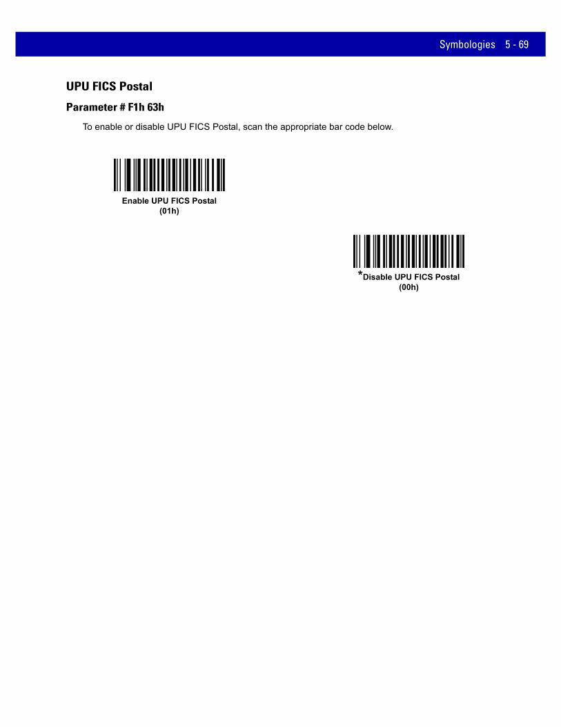
Symbologies 5 - 69
UPU FICS Postal
Parameter # F1h 63h
To enable or disable UPU FICS Postal, scan the appropriate bar code below.
Enable UPU FICS Postal(01h)
*Disable UPU FICS Postal(00h)

5 - 70 MX101 PRODUCT REFERENCE GUIDE
GS1 DataBarGS1 DataBar types are:
• GS1 DataBar Omnidirectional
• GS1 DataBar Truncated
• GS1 DataBar Stacked
• GS1 DataBar Stacked Omnidirectional
• GS1 DataBar Limited
• GS1 DataBar Expanded
• GS1 DataBar Expanded Stacked
Scan the appropriate bar codes to enable or disable each type of GS1 DataBar.
GS1 DataBar
Parameter # F0h 52h
Scan the appropriate bar code below to enable or disable the following code types:
• GS1 DataBar Omnidirectional
• GS1 DataBar Truncated
• GS1 DataBar Stacked
• GS1 DataBar Stacked Omnidirectional,
*Enable GS1 DataBar(01h)
Disable GS1 DataBar(00h)

Symbologies 5 - 71
GS1 DataBar Limited
Parameter # F0h 53h
Enable GS1 DataBar Limited(01h)
*Disable GS1 DataBar Limited(00h)

5 - 72 MX101 PRODUCT REFERENCE GUIDE
GS1 DataBar Limited Security Level
Parameter # F1h D8h
The scanner offers four levels of decode security for GS1 DataBar Limited bar codes. There is an inverse relationship between security and scanner aggressiveness. Increasing the level of security may result in reduced aggressiveness in scanning, so only choose the level of security necessary.
• Level 1 – No clear margin required. This complies with the original GS1 standard, yet might result in
erroneous1 decoding of the DataBar Limited bar code when scanning some UPC symbols that start with the digits “9” and “7”.
• Level 2 – Automatic risk detection. This level of security may result in erroneous decoding of DataBar Limited bar codes when scanning some UPC symbols. If a misdecode is detected, the scanner operates in Level 3 or Level 1.
• Level 3 – Security level reflects newly proposed GS1 standard that requires a 5X trailing clear margin.
• Level 4 – Security level extends beyond the standard required by GS1. This level of security requires a 5X leading and trailing clear margin.
1.May result in erroneous decoding due to Databar Limited and UPC symbologies.
Security Level 1(01h)
Security Level 2(02h)
*Security Level 3(03h)
Security Level 4(04h)

Symbologies 5 - 73
GS1 DataBar Expanded
Parameter # F0h 54h
Scan the appropriate bar code below to enable or disable the following code types:
• GS1 DataBar Expanded
• GS1 DataBar Expanded Stacked.
Convert GS1 DataBar to UPC/EAN
Parameter # F0h, 8Dh
This parameter only applies to GS1 DataBar and GS1 DataBar Limited symbols not decoded as part of a Composite symbol. Enable this to strip the leading '010' from DataBar and DataBar Limited symbols encoding a single zero as the first digit, and report the bar code as EAN-13.
For bar codes beginning with two or more zeros but not six zeros, this parameter strips the leading '0100' and reports the bar code as UPC-A. The UPC-A Preamble parameter that transmits the system character and country code applies to converted bar codes. Note that neither the system character nor the check digit can be stripped.
Enable GS1 DataBar Expanded(01h)
*Disable GS1 DataBar Expanded(00h)
Enable Convert GS1 DataBar to UPC/EAN(01h)
*Disable Convert GS1 DataBar to UPC/EAN(00h)

5 - 74 MX101 PRODUCT REFERENCE GUIDE
Composite
Composite CC-C
Parameter # F0h 55h
Scan a bar code below to enable or disable Composite bar codes of type CC-C.
Composite CC-A/B
Parameter # F0h 56h
Scan a bar code below to enable or disable Composite bar codes of type CC-A/B.
Enable CC-C(01h)
*Disable CC-C(00h)
NOTE If you enable this code type, also see UPC Composite Mode on page 5-75.
Enable CC-A/B(01h)
*Disable CC-A/B(00h)

Symbologies 5 - 75
Composite TLC-39
Parameter # F0h 73h
Scan a bar code below to enable or disable Composite bar codes of type TLC-39.
UPC Composite Mode
Parameter # F0h 58hIf you enable Composite CC-A/B on page 5-74, select an option for linking UPC symbols with a 2D symbol during transmission as if they were one symbol:
• Select UPC Never Linked to transmit UPC bar codes regardless of whether a 2D symbol is detected.
• Select UPC Always Linked to transmit UPC bar codes and the 2D portion. If 2D is not present, the UPC bar code does not transmit.
• If you select Autodiscriminate UPC Composites, the scanner determines if there is a 2D portion, then transmits the UPC, as well as the 2D portion if present.
Enable TLC39(01h)
*Disable TLC39(00h)
*UPC Never Linked(00h)
UPC Always Linked(01h)
Autodiscriminate UPC Composites(02h)

5 - 76 MX101 PRODUCT REFERENCE GUIDE
Composite Beep Mode
Parameter # F0h, 8Eh
To select the number of decode beeps when a composite bar code is decoded, scan the appropriate bar code.
GS1-128 Emulation Mode for UCC/EAN Composite Codes
Parameter # F0h, ABh
Select whether to enable or disable this mode.
Single Beep After Both are Decoded(00h)
*Beep as Each Code Type is Decoded(01h)
Double Beep After Both are Decoded(02h)
Enable GS1-128 Emulation Mode for UCC/EAN Composite Codes
(01h)
*Disable GS1-128 Emulation Mode for UCC/EAN Composite Codes
(00h)

Symbologies 5 - 77
2D Symbologies
Enable/Disable PDF417
Parameter # 0Fh
To enable or disable PDF417, scan the appropriate bar code below.
Enable/Disable MicroPDF417
Parameter # E3h
To enable or disable MicroPDF417, scan the appropriate bar code below.
Enable PDF417(01h)
*Disable PDF417(00h)
Enable MicroPDF417(01h)
*Disable MicroPDF417(00h)

5 - 78 MX101 PRODUCT REFERENCE GUIDE
Code 128 Emulation
Parameter # 7Bh
Enable this parameter to transmit data from certain MicroPDF417 symbols as Code 128. AIM Code ID Character (01h) on page 4-20 must be enabled for this parameter to work.
Enable Code 128 Emulation to transmit these MicroPDF417 symbols with one of the following prefixes:
]C1 if the first codeword is 903-905
]C2 if the first codeword is 908 or 909
]C0 if the first codeword is 910 or 911
Disable Code 128 Emulation to transmit these MicroPDF417 symbols with one of the following prefixes:
]L3 if the first codeword is 903-905
]L4 if the first codeword is 908 or 909
]L5 if the first codeword is 910 or 911
Scan a bar code below to enable or disable Code 128 Emulation.
NOTE Linked MicroPDF codewords 906, 907, 912, 914, and 915 are not supported. Use GS1 Composites instead.
Enable Code 128 Emulation(01h)
*Disable Code 128 Emulation(00h)

Symbologies 5 - 79
Data Matrix
Parameter # F0h, 24h
To enable or disable Data Matrix, scan the appropriate bar code below.
Data Matrix Inverse
Parameter # F1h 4Ch
This parameter sets the Data Matrix inverse scanner setting. Options are:
• Regular Only - the scanner decodes regular Data Matrix bar codes only.
• Inverse Only - the scanner decodes inverse Data Matrix bar codes only.
• Inverse Autodetect - the scanner decodes both regular and inverse Data Matrix bar codes.
Enable Data Matrix(01h)
*Disable Data Matrix(00h)
*Regular(00h)
Inverse Only(01h)
Inverse Autodetect(02h)

5 - 80 MX101 PRODUCT REFERENCE GUIDE
Decode Mirror Images (Data Matrix Only)
Parameter # F1h 19h
Select an option for decoding mirror image Data Matrix bar codes:
• Always - decode only Data Matrix bar codes that are mirror images
• Never - do not decode Data Matrix bar codes that are mirror images
• Auto - decode both mirrored and unmirrored Data Matrix bar codes.
Never(00h)
Always(01h)
* Auto(02h)

Symbologies 5 - 81
Maxicode
Parameter # F0h, 26h
To enable or disable Maxicode, scan the appropriate bar code below.
QR Code
Parameter # F0h,25h
To enable or disable QR Code, scan the appropriate bar code below.
Enable Maxicode(01h)
*Disable Maxicode(00h)
Enable QR Code(01h)
*Disable QR Code(00h)

5 - 82 MX101 PRODUCT REFERENCE GUIDE
QR Inverse
Parameter # F1h 4Bh
This parameter sets the QR inverse scanner setting. Options are:
• Regular Only - the scanner decodes regular QR bar codes only.
• Inverse Only - the scanner decodes inverse QR bar codes only.
• Inverse Autodetect - the scanner decodes both regular and inverse QR bar codes.
MicroQR
Parameter # F1h 3Dh
To enable or disable MicroQR, scan the appropriate bar code below.
*Regular(00h)
Inverse Only(01h)
Inverse Autodetect(02h)
Enable MicroQR(01h)
*Disable MicroQR(00h)

Symbologies 5 - 83
Aztec
Parameter # F1h 3Eh
To enable or disable Aztec, scan the appropriate bar code below.
Aztec Inverse
Parameter # F1h 4Dh
This parameter sets the Aztec inverse scanner setting. Options are:
• Regular Only - the scanner decodes regular Aztec bar codes only.
• Inverse Only - the scanner decodes inverse Aztec bar codes only.
• Inverse Autodetect - the scanner decodes both regular and inverse Aztec bar codes.
Enable Aztec (01h)
*Disable Aztec (00h)
Regular(00h)
Inverse Only(01h)
*Inverse Autodetect(02h)

5 - 84 MX101 PRODUCT REFERENCE GUIDE
Redundancy Level
Parameter # 4Eh
The scanner offers four levels of decode redundancy. Select higher redundancy levels for decreasing levels of bar code quality. As redundancy levels increase, the scanner’s aggressiveness decreases.
Select the redundancy level appropriate for the bar code quality.
Redundancy Level 1
The following code types must be successfully read twice before being decoded:
Redundancy Level 2
The following code types must be successfully read twice before being decoded:
Redundancy Level 3
Code types other than the following must be successfully read twice before being decoded. The following codes must be read three times:
Table 5-2 Redundancy Level 1 Codes
Code Type Code Length
Codabar 8 characters or less
MSI 4 characters or less
D 2 of 5 8 characters or less
I 2 of 5 8 characters or less
Table 5-3 Redundancy Level 2 Codes
Code Type Code Length
All All
Table 5-4 Redundancy Level 3 Codes
Code Type Code Length
MSI 4 characters or less
D 2 of 5 8 characters or less
I 2 of 5 8 characters or less
Codabar 8 characters or less

Symbologies 5 - 85
Redundancy Level 4
The following code types must be successfully read three times before being decoded:
Table 5-5 Redundancy Level 4 Codes
Code Type Code Length
All All
*Redundancy Level 1(01h)
Redundancy Level 2(02h)
Redundancy Level 3(03h)
Redundancy Level 4(04h)

5 - 86 MX101 PRODUCT REFERENCE GUIDE
Security Level
Parameter # 4Dh
The scanner offers four levels of decode security for delta bar codes, which include UPC/EAN and Code 93. Select increasing levels of security for decreasing levels of bar code quality. There is an inverse relationship between security and scanner aggressiveness, so choose only that level of security necessary for any given application.
• Security Level 0: This setting allows the scanner to operate in its most aggressive state, while providing sufficient security in decoding most “in-spec” bar codes.
• Security Level 1: This default setting eliminates most misdecodes.
• Security Level 2: Select this option if Security level 1 fails to eliminate misdecodes.
• Security Level 3: If you selected Security Level 2 and misdecodes still occur, select this security level. Be advised, selecting this option is an extreme measure against mis-decoding severely out of spec bar codes. Selecting this level of security significantly impairs the decoding ability of the scanner. If you need this level of security, try to improve the quality of the bar codes.
Security Level 0(00h)
*Security Level 1(01h)
Security Level 2(02h)
Security Level 3(03h)
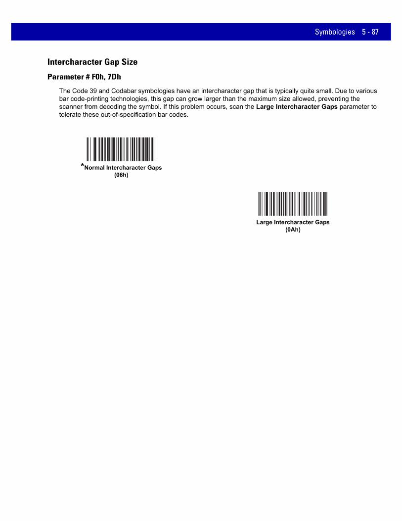
Symbologies 5 - 87
Intercharacter Gap Size
Parameter # F0h, 7Dh
The Code 39 and Codabar symbologies have an intercharacter gap that is typically quite small. Due to various bar code-printing technologies, this gap can grow larger than the maximum size allowed, preventing the scanner from decoding the symbol. If this problem occurs, scan the Large Intercharacter Gaps parameter to tolerate these out-of-specification bar codes.
*Normal Intercharacter Gaps(06h)
Large Intercharacter Gaps(0Ah)

5 - 88 MX101 PRODUCT REFERENCE GUIDE
Macro PDF Features Macro PDF is a special feature for concatenating multiple PDF symbols into one file. The scanner can decode symbols that are encoded with this feature, and can store more than 64 Kb of decoded data stored in up to 50 MacroPDF symbols.
Macro PDF User Indications
In this mode the scanner provides the following feedback.
CAUTION When printing, keep each Macro PDF sequence separate, as each sequence has unique identifiers. Do not mix bar codes from several Macro PDF sequences, even if they encode the same data. When scanning Macro PDF sequences, scan the entire sequence without interruption. When scanning a mixed sequence, two long low beeps (Low/Low) indicates an inconsistent file ID or inconsistent symbology error.
Table 5-6 Macro PDF User Indications
User ScansPassthrough All
SymbolsTransmit Any Symbol in Set Buffer All Symbols
Beep T Beep T Beep T
Last Macro PDF in set Decode Beep Y Decode Beep Y Decode Beep Y
Any Macro PDF in set except last Decode Beep Y Decode Beep Y 2 Short Low N
Macro PDF is not in current Set Decode Beep Y 2 Long Low N 2 Long Low N
Invalid formatted Macro PDF Decode Beep Y 2 Long Low N 2 Long Low N
Macro PDF from a set has already been scanned
Decode Beep Y 4 Long Low N 4 Long Low N
Out of Macro PDF memory N/A 3 Long Low N 3 Long Low N
Any non-Macro PDF scanned during a set
N/A - 4 Long Low N 4 Long Low N
Flush Macro PDF Low High N 5 Long Low N 5 Long Low Y
Abort Macro PDF High Low High Low
N High Low High Low N
High Low High Low N
Notes:1. The beep only sounds if the *BEEPER_ON signal is connected.2. The column marked T indicates whether the symbol is transmitted to the host. N = No transmission.

Symbologies 5 - 89
Macro PDF Transmit / Decode Mode Symbols
Parameter # BCh
Select one of the options below for handling Macro PDF decoding. In Buffer All Symbols the scanner can handle sets of up to 50 maximum-sized Macro PDF symbols. In all other modes there is no limit to the size of the MacroPDF set.
• Buffer All Symbols / Transmit Macro PDF When Complete: This transmits all decode data from an entire Macro PDF sequence only when the entire sequence is scanned and decoded. Use the beeper and LED signals provided with the scanner when using this mode to ensure proper user feedback. If the decode data exceeds the limit of 50 symbols, there is no transmission because the entire sequence was not scanned. Use the parameter Flush Macro Buffer on page 5-91 to purge the buffer.
• Transmit Any Symbol in Set / No Particular Order: This transmits data from each Macro PDF symbol as decoded, regardless of the sequence (although some error handling is performed; see Table 5-6). When selecting this mode, enable Transmit Macro PDF Control Header on page 5-90. Also use the beeper and LED signals provided with the scanner to ensure proper user feedback.
• Passthrough All Symbols: This transmits and decodes all Macro PDF symbols and performs no processing. In this mode the host is responsible for detecting and parsing the Macro PDF sequences.
Use this mode when the scanner’s BEEPER_ON signal is not used to drive a beeper. In the other modes, some Macro PDF scanning sequences provide audible feedback only, so if BEEPER_ON is not used no user feedback is provided. In Table 5-6, all actions marked No Transmission provide no feedback unless the BEEPER_ON signal is used. By using Passthrough All Symbols mode every user decode is transmitted to the host where the host software can provide the appropriate feedback.
Buffer All Symbols /Transmit Macro PDF When Complete
(00h)
Transmit Any Symbol in Set / No Particular Order(01h)
*Passthrough All Symbols(04h)

5 - 90 MX101 PRODUCT REFERENCE GUIDE
Transmit Macro PDF Control Header
Parameter # B8h
When enabled, this activates transmission of the control header, which contains the segment index and the file ID, in Macro PDF symbols. For example, the field may be: \92800000\725\120\343. The five digits after the \928 are the segment index (or block index), and \725\120\343 is the file ID.
Enable this when selecting Transmit Any Symbol in Set / No Particular Order for the Macro PDF Transmit / Decode Mode Symbols on page 5-89, and disable this when selecting Buffer All Symbols / Transmit Macro PDF When Complete. This parameter has no effect when Passthrough All Symbols is selected.
Escape Characters
Parameter # E9h
This enables the backslash (\) character as an Escape character for systems that can process transmissions containing special data sequences. Scan a bar code below to either format special data according to the GLI (Global Label Identifier) protocol, or to disable this parameter. This parameter only affects the data portion of a Macro PDF symbol transmission; the Macro PDF Control Header (if enabled) is always sent with GLI formatting.
*Enable Macro PDF Control Header Transmit(01h)
Disable Macro PDF Control Header Transmit(00h)
GLI Protocol(02h)
*None(00h)

Symbologies 5 - 91
Flush Macro Buffer
This flushes the buffer of all decoded Macro PDF data stored to that point, transmits it to the host device, and aborts from Macro PDF mode.
Abort Macro PDF Entry
This clears all currently-stored Macro PDF data in the buffer without transmission and aborts from Macro PDF mode.
Flush Macro PDF Buffer
Abort Macro PDF Entry

5 - 92 MX101 PRODUCT REFERENCE GUIDE

CHAPTER 6 123SCAN2
Introduction123Scan² is an easy-to-use, PC-based software tool that enables the quick and easy setup of Zebra scanners.
123Scan² uses a wizard tool to guide users through a streamlined set up process. Once parameters are set, the values are saved to a configuration file that can be distributed via e-mail, electronically downloaded via a USB cable, or used to generate a sheet of programming bar codes that can be scanned. 123Scan² can generate multiple reports that can be easily rebranded using Microsoft Word or Access. Report options include programmed parameters, asset tracking information and proof of scanner output.
Additionally, 123Scan² can display scanned bar code data including non-printable characters. It can display, optimize and save pictures from an imaging scanner. It can also upgrade scanner firmware, automatically check online to enable support for newly released products, generate a single 2D bar code for one scan programming and stage large numbers of scanners simultaneously via USB hub(s).
Communication with 123Scan2
To communicate with the 123Scan² program which runs on a host computer running a Windows XP SP2 and Windows 7 operating system, use a USB cable to connect the MP6000 to the host computer.

6 - 2 MX101 PRODUCT REFERENCE GUIDE
123Scan2 Requirements• Host computer with Windows XP SP2 or Windows 7
• Scanner
• USB cable.
For more information on123Scan², go to: http://www.zebra.com/123scan2
For a 1 minute tour of 123Scan², go to: http://www.zebra.com/scannersoftwarevideos
To download 123Scan² software and access the Help file integrated in the utility, go to:http://www.zebra.com/123scan2
Scanner SDK, Other Software Tools, and VideosTackle all your scanner programming needs with our diversified set of software tools. Whether you need to simply stage a device, or develop a fully featured application with image and data capture as well as asset management, these tools help you every step of the way. To download any of the free tools listed below, go to:www.zebra.com/software.
• 123Scan2 Configuration Utility (described in this chapter)
• Scanner SDK for Windows
• How-to-Videos
• Virtual Com Port Driver
• OPOS Driver
• JPOS Driver
• Scanner User Documentation
• Archive of Older Drivers.

CHAPTER 7 ADVANCED DATA FORMATTING
IntroductionAdvanced Data Formatting (ADF) is a means of customizing data before transmission to the host device. Use ADF to edit scan data to suit requirements. Implement ADF by scanning a related series of bar codes which program the scanner with ADF rules.
For information and programming bar codes for ADF, refer to the Advanced Data Formatting Programmer Guide, p/n 72E-69680-xx.

7 - 2 MX101 PRODUCT REFERENCE GUIDE

CHAPTER 8 INSTALLING THE MX101 CUSTOMER SIDE SCANNER
IntroductionThis chapter provides instructions to install the MX101 Customer Side Scanner (CSS) into the MP6000 multi-plane imaging scanner, and affix the MX101 identification label.
The MX101 CSS optional modular unit replaces the MP6000 tower cover. The unit can be installed on either the left, or right side of the MP6000. Remove all hardware from the packaging.
Figure 8-1 MX101 Parts
Scan Window
CSS Tower Cover
USB Cable
Scan Window Cover
Identification Label
CSS Blank Side Cover
Scan Module
xxxxxxxxxxx
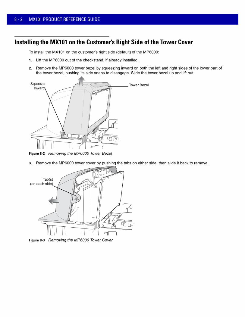
8 - 2 MX101 PRODUCT REFERENCE GUIDE
Installing the MX101 on the Customer’s Right Side of the Tower CoverTo install the MX101 on the customer’s right side (default) of the MP6000:
1. Lift the MP6000 out of the checkstand, if already installed.
2. Remove the MP6000 tower bezel by squeezing inward on both the left and right sides of the lower part of the tower bezel, pushing its side snaps to disengage. Slide the tower bezel up and lift out.
Figure 8-2 Removing the MP6000 Tower Bezel
3. Remove the MP6000 tower cover by pushing the tabs on either side; then slide it back to remove.
Figure 8-3 Removing the MP6000 Tower Cover
Tower BezelSqueezeInward
Tab(s)(on each side)

Installing the MX101 Customer Side Scanner 8 - 3
4. After removing the tower cover, ensure the speaker wire ferrite is in the correct position, behind the tabs as shown in Figure 8-4. Failure to properly route the wire may cause the wire to pinch when the tower cover is replaced.
Figure 8-4 Speaker Wire Ferrite Placement
5. Remove the scan window cover from the CSS tower by squeezing the snaps shown below.
Figure 8-5 Removing the Scan Window Cover
6. Determine the side of the MP6000 to which the MX101 should be installed. The default is the customer’s right side (the side of the MX101 tower cover already open for the scan module to be inserted).
NOTE See Installing the MX101 on the Customer’s Left Side of the Tower Cover on page 8-8 to install the scan module on the customer’s left side of the tower cover.
Ferritetabs
Snaps

8 - 4 MX101 PRODUCT REFERENCE GUIDE
7. Insert the scan module into place facing out of the opening of the CSS tower cover. Ensure the grommets on the scan module align with the holes in the tower cover, and push into place.
Figure 8-6 Inserting the Scan Module
8. Snap the scan window cover into place on the tower, over the scan window.
Figure 8-7 Adding the Scan Window Cover
Scan Module
CSS TowerCover
Grommets (3)
GrommetHoles (3)
Module Installed

Installing the MX101 Customer Side Scanner 8 - 5
9. Connect the USB cable to the top USB port (recommended) on the MP6000. Route the cable into the side cable slots as shown.
Figure 8-8 Connecting the Cable
10. Route the cable, looping through the right side cable slots as shown below. (Cable wire should be tight.)
Figure 8-9 Routing the Cable
Top USB Port
Side Cable Slots
Cable Slots
Service Loop
Cable Slots

8 - 6 MX101 PRODUCT REFERENCE GUIDE
11. Connect the cable to the micro USB port at the bottom of the scan module. Ensure the cable is clipped into the scan module plastic directly below the USB port.
Figure 8-10 Connecting the Cable to the Micro USB Port
12. Slide the CSS tower cover back into place. Ensure the cable service loop folds up into the blank space in the CSS tower cover, on the opposite side of the scan module. Snaps should click together. When the tower cover is replaced, the module locks into the grommet compression ribs on the MP6000.
Figure 8-11 Replacing the Tower Cover
Micro USB Port
ServiceLoop
Scan Module Cable
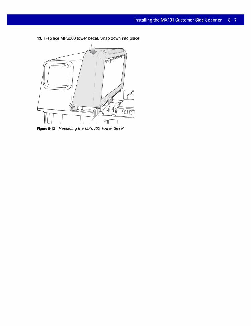
Installing the MX101 Customer Side Scanner 8 - 7
13. Replace MP6000 tower bezel. Snap down into place.
Figure 8-12 Replacing the MP6000 Tower Bezel

8 - 8 MX101 PRODUCT REFERENCE GUIDE
Installing the MX101 on the Customer’s Left Side of the Tower CoverTo install the MX101 on the left side of the MP6000:
1. Push out the CSS blank side cover on the left side of the CSS tower cover, and replace the cover into the opening on the right side of the tower cover.
Figure 8-13 Pushing Out the Blank Side Cover
2. Repeat steps 1, 2, 8-2, and 4 from Installing the MX101 on the Customer’s Right Side of the Tower Cover on page 8-2.
3. Insert the scan module into place facing out of the left side opening of the CSS tower cover. Ensure the grommets on the scan module align with the holes in the tower cover, and push into place.
4. Snap the scan window cover into place on the tower, over the scan window.
5. Connect the USB cable to the top USB port (recommended) on the MP6000 and route the cable through the side cable slots shown in step 9 on page 5.
6. Route the cable, looping through the left side cable slots as shown below.
Figure 8-14 Routing the Cable
Cable Slots for Left Side Installation
Scan Module Cable Clip

Installing the MX101 Customer Side Scanner 8 - 9
7. Connect the cable to the micro USB port on the bottom of the scan module. Ensure the cable is clipped into the scan module plastic directly below the USB port.
8. Slide the CSS tower cover back into place. Ensure the cable service loop folds up into the blank space in the CSS tower cover, on the opposite side of the scan module. Snaps should click together. When the tower cover is replaced, the module locks into the grommet compression ribs on the MP6000.
9. Replace MP6000 tower bezel. Snap down into place.

8 - 10 MX101 PRODUCT REFERENCE GUIDE
Affixing the MX101 Identification Label to the MP6000The MX101 identification label included in the MX101 packaging must be affixed to the MP6000 as shown below. Failure to affix the label to the MP6000 voids the MX101 warranty.
1. Peel the label from its backing.
Figure 8-15 MX101 Identification Label
2. Affix the label to the indentation under the MP6000 platter.
Figure 8-16 Affixing to the MP6000
XXXXXXXXXX
XXXXXXXXXX
MP6000 View Under Platter
CHAPTER 9 MAINTENANCE, TROUBLESHOOTING, AND SIGNAL DESCRIPTIONS
IntroductionThis chapter provides suggested digital scanner maintenance, troubleshooting, and pinout signal descriptions.
MaintenanceCleaning the scan window is the only maintenance required. A dirty window can affect scanning accuracy.
• Do not allow abrasive material to touch the window.
• Remove any dirt particles with a damp cloth.
• Wipe the window using a dust-free soft cloth moistened with isopropyl alcohol-based cleaner. Do not let liquid pool around the window or any other area on the scanner.
• Do not spray water or other cleaning liquids directly into the window.

9 - 2 MX101 PRODUCT REFERENCE GUIDE
TroubleshootingTable 9-1 Troubleshooting
Problem Possible Causes Possible Solutions
Digital scanner emits short low/short medium/short high beep sequence (power-up beep sequence) more than once.
The USB bus may put the digital scanner in a state where power to the scanner is cycled on and off more than once.
Normal during host reset.
Digital scanner emits illumination, but does not decode the bar code.
Digital scanner is not programmed for that bar code type.
Program the digital scanner to read that type of bar code. See Chapter 5, Symbologies.
Bar code symbol is unreadable. Scan test symbols of the same bar code type to determine if the bar code is defaced.
Digital scanner decodes bar code, but does not transmit the data to the host.
USB interface cable is loose. Re-connect the cable.
If the digital scanner emits 5 low beeps, a conversion or format error occurred.
Configure the digital scanner's conversion parameters properly.
If the digital scanner emits low/high/low beeps, it detected an invalid ADF rule.
Program the correct ADF rules. Refer to the Advanced Data Formatting Programmer Guide.
If the digital scanner emits high/low beeps, the scanner is buffering Code 39 data.
Normal scanning a Code 39 bar code and the Code 39 Buffering option is enabled.
Digital scanner emits low/high beeps during programming.
Input error or Cancel bar code was scanned.
Scan the correct numeric bar codes within range for the parameter programmed.
Digital scanner emits low/high/low/high beeps during programming.
Out of ADF parameter storage space.
Erase all rules and re-program with shorter rules.
Digital scanner emits low/high/low beeps.
Clearing Code 39 buffer. Normal when scanning the Code 39 Buffering Clear Buffer bar code or upon attempt to transmit an empty Code 39 buffer.
NOTE If after performing these checks the digital scanner still experiences problems, contact the distributor or Zebra support. See page xi for contact information.

Maintenance, Troubleshooting, and Signal Descriptions 9 - 3
Report Software Version Bar Code
When contacting Zebra support, a support representative may ask you to scan the bar code below to determine the version of software installed in the digital scanner.
Report Software Version

9 - 4 MX101 PRODUCT REFERENCE GUIDE
Digital Scanner Signal Descriptions
Figure 9-1 Digital Scanner Cable Pinouts
The signal descriptions in Table 9-2 apply to the connector on the MX101 digital scanner.
Micro-B
1 5
Table 9-2 USB Connector Pin-outs
Pin Signal Function
1 5VDC USB 5V
2 D- USB Data-
3 D+ USB Data+
4 DOWNLOAD Active High
Download PIN
5 GND Circuit GND
SHELL GND_CHAS Chassis GND

Maintenance, Troubleshooting, and Signal Descriptions 9 - 5

9 - 6 MX101 PRODUCT REFERENCE GUIDE

APPENDIX A STANDARD DEFAULT PARAMETERS
Table A-1 Standard Default Parameters Table
Parameter Parameter Number Default Page
Number
USB Parameters
USB Host Parameter Symbol Native API (SNAPI) with Imaging Interface
3-2
IBM Specification Version Original Specification 3-3
User Preferences
Set Default Parameter Restore Defaults 4-4
Parameter Bar Code Scanning ECh Enable 4-5
Lock Parameter Scanning F2h 22h Disable 4-6
Unlock Parameter Scanning F2h 23h Disable 4-6
Beep After Good Decode 38h Enable 4-7
Beeper Tone 91h High 4-8
Beeper Volume 8Ch High 4-9
Beeper Duration F1h 74h Long 4-10
Suppress Power-up Beeps F1h D1h Do not suppress 4-10
Trigger Modes 8Ah Presentation Mode 4-11
Decode Session Timeout 88h 9.9 Sec 4-11
Timeout Between Decodes, Same Symbol 89h 0.6 Sec 4-12
Timeout Between Decodes, Different Symbols 90h 0.2 Sec 4-12
1User selection is required to configure this interface and this is the most common selection.

A - 2 MX101 PRODUCT REFERENCE GUIDE
Motion Detect Range F2h 3Bh Short Range 4-13
Range Restrict F1h 75h 3 inches 4-14
Presentation Mode Field of View F1h 61h Medium Field of View 4-15
Fuzzy 1D Processing F1h 02h Enable 4-16
Mirrored Image F1h 70h Disable 4-16
Mobile Phone/Display Mode F1h CCh Enable 4-17
Validate Concatenated Parameter Bar Codes F1h B4h Disable 4-17
Illumination Brightness F0h 9Dh 6 4-18
Decoding Illumination F0h 2Ah Enable 4-18
Decode Aiming Pattern F0h 32h Disable 4-19
Miscellaneous Scanning Parameters
Transmit Code ID Character 2Dh None 4-20
SSI Prefix Value 69h <CR> 4-21
SSI Suffix 1 Value
SSI Suffix 2 Value
68h
6Ah
<CR>
<CR>
4-21
Scan Data Transmission Format EBh Data as is 4-22
Report Version 4-24
Report Scanner Manufacturing Version 4-24
Report Scan Engine Manufacturing Version 4-24
USB Host Parameters
USB Device Type SNAPI with Imaging 3-2
Symbology Parameters
Disable All Code Types 5-8
UPC/EAN
UPC-A 01h Disable 5-9
UPC-E 02h Disable 5-9
UPC-E1 0Ch Disable 5-10
EAN-8/JAN 8 04h Disable 5-10
EAN-13/JAN 13 03h Disable 5-11
Bookland EAN 53h Disable 5-11
Table A-1 Standard Default Parameters Table (Continued)
Parameter Parameter Number Default Page
Number
1User selection is required to configure this interface and this is the most common selection.

Standard Default Parameters A - 3
Bookland ISBN Format F1h 40h ISBN-10 5-12
Decode UPC/EAN/JAN Supplementals (2 and 5 digits)
10h Ignore 5-13
User-Programmable Supplementals
Supplemental 1:
Supplemental 2:
F1h 43h
F1h 44h
N/A 5-16
UPC/EAN/JAN Supplemental Redundancy 50h 10 5-16
Decode UPC/EAN/JAN Supplemental AIM ID F1h A0h Combined 5-17
Transmit UPC-A Check Digit 28h Enable 5-18
Transmit UPC-E Check Digit 29h Enable 5-18
Transmit UPC-E1 Check Digit 2Ah Enable 5-19
UPC-A Preamble 22h System Character 5-19
UPC-E Preamble 23h System Character 5-20
UPC-E1 Preamble 24h System Character 5-21
Convert UPC-E to A 25h Disable 5-22
Convert UPC-E1 to A 26h Disable 5-22
EAN-8/JAN-8 Extend 27h Disable 5-23
UCC Coupon Extended Code 55h Disable 5-23
Coupon Report F1h DAh New Coupon Symbols 5-24
ISSN EAN F1h 69h Disable 5-25
Code 128
Code 128 08h Enable 5-26
Set Length(s) for Code 128 D1h, D2h Any Length 5-26
GS1-128 (formerly UCC/EAN-128) 0Eh Disable 5-27
ISBT 128 54h Disable 5-28
ISBT Concatenation F1h 41h Disable 5-29
Check ISBT Table F1h 42h Enable 5-30
ISBT Concatenation Redundancy DFh 10 5-30
Code 39
Code 39 00h Disable 5-31
Trioptic Code 39 0Dh Disable 5-31
Table A-1 Standard Default Parameters Table (Continued)
Parameter Parameter Number Default Page
Number
1User selection is required to configure this interface and this is the most common selection.

A - 4 MX101 PRODUCT REFERENCE GUIDE
Convert Code 39 to Code 32 (Italian Pharmacy Code)
56h Disable 5-32
Code 32 Prefix E7h Disable 5-32
Set Length(s) for Code 39 12h, 13h Length Within Range: 2 to 55 5-33
Code 39 Check Digit Verification 30h Disable 5-34
Transmit Code 39 Check Digit 2Bh Disable 5-34
Code 39 Full ASCII Conversion 11h Disable 5-35
Buffer Code 39 71h Disable 5-36
Code 93
Code 93 09h Disable 5-38
Set Length(s) for Code 93 1Ah, 1Bh Length Within Range: 4 to 55 5-38
Code 11
Code 11 0Ah Disable 5-40
Set Lengths for Code 11 1Ch, 1Dh Length Within Range: 4 to 55 5-40
Code 11 Check Digit Verification 34h Disable 5-42
Transmit Code 11 Check Digit(s) 2Fh Disable 5-43
Interleaved 2 of 5 (ITF)
Interleaved 2 of 5 (ITF) 06h Disable 5-44
Set Lengths for I 2 of 5 16h, 17h 1 Length; Length = 14
5-44
I 2 of 5 Check Digit Verification 31h Disable 5-46
Transmit I 2 of 5 Check Digit 2Ch Disable 5-46
Convert I 2 of 5 to EAN 13 52h Disable 5-47
Discrete 2 of 5 (DTF)
Discrete 2 of 5 05h Disable 5-48
Set Length(s) for D 2 of 5 14h, 15h 1 Length; Length = 12
5-48
Codabar (NW - 7)
Codabar 07h Disable 5-50
Set Lengths for Codabar 18h, 19h Length Within Range: 5 to 55 5-50
CLSI Editing 36h Disable 5-52
Table A-1 Standard Default Parameters Table (Continued)
Parameter Parameter Number Default Page
Number
1User selection is required to configure this interface and this is the most common selection.

Standard Default Parameters A - 5
NOTIS Editing 37h Disable 5-52
Codabar Upper or Lower Case Start/Stop Characters Detection
F2h 57h Upper Case 5-53
MSI
MSI 0Bh Disable 5-54
Set Length(s) for MSI 1Eh, 1Fh Length Within Range: 4 to 55 5-54
MSI Check Digits 32h One 5-56
Transmit MSI Check Digit 2Eh Disable 5-56
MSI Check Digit Algorithm 33h Mod 10/Mod 10 5-57
Chinese 2 of 5
Chinese 2 of 5 F0h 98h Disable 5-57
Matrix 2 of 5
Matrix 2 of 5 F1h 6Ah Disable 5-58
Matrix 2 of 5 Lengths F1h 6BhF1h 6Ch
Length; Length = Any Length
5-59
Matrix 2 of 5 Check Digit F1h 6Eh Disable 5-60
Transmit Matrix 2 of 5 Check Digit F1h 6Fh Disable 5-60
Korean 3 of 5
Korean 3 of 5 F1h 45h Disable 5-61
Inverse 1D F1h 4Ah Regular 5-62
Postal Codes
US Postnet 59h Disable 5-63
US Planet 5Ah Disable 5-63
Transmit US Postal Check Digit 5Fh Enable 5-64
UK Postal 5Bh Disable 5-64
Transmit UK Postal Check Digit 60h Enable 5-65
Japan Postal F0h 22h Disable 5-65
Australia Post F0h 23h Disable 5-66
Australia Post Format F1h CEh Autodiscriminate 5-67
Netherlands KIX Code F0h 46h Disable 5-68
Table A-1 Standard Default Parameters Table (Continued)
Parameter Parameter Number Default Page
Number
1User selection is required to configure this interface and this is the most common selection.
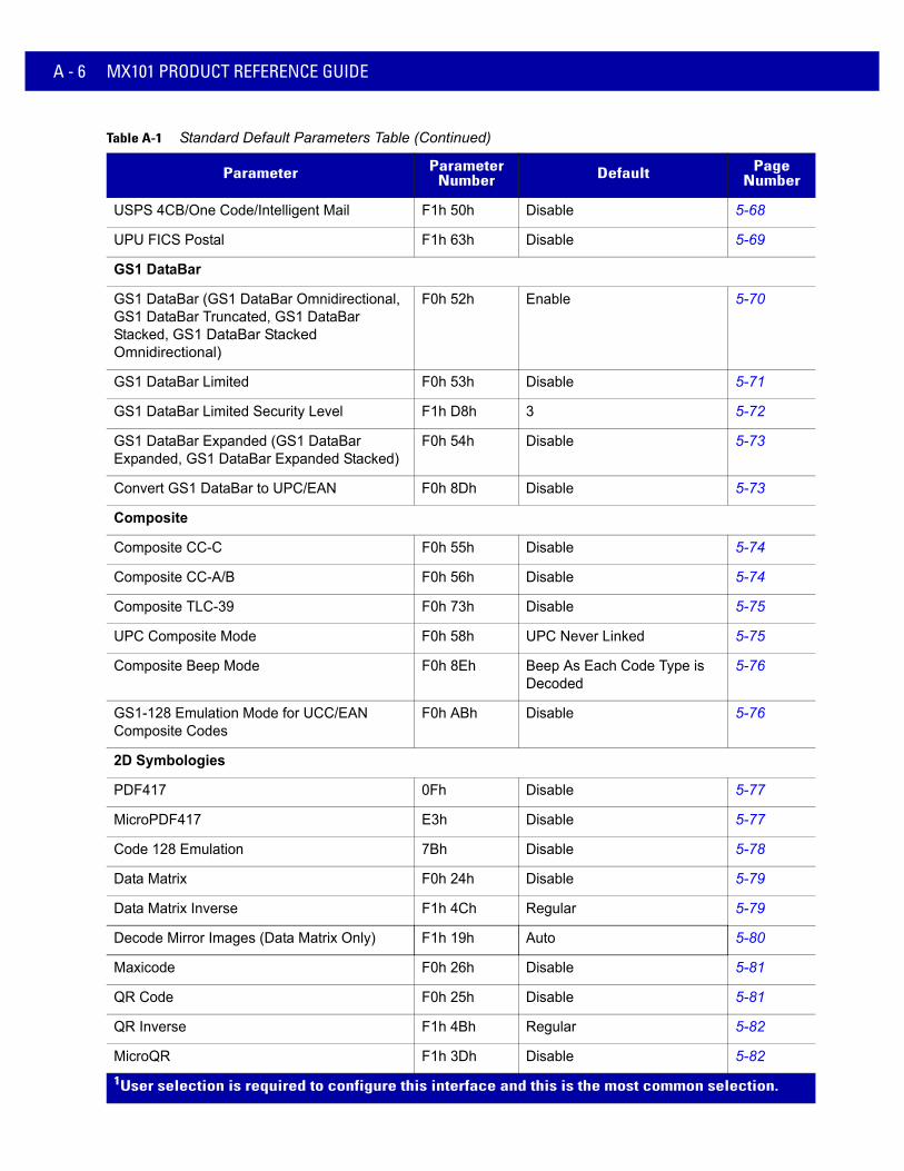
A - 6 MX101 PRODUCT REFERENCE GUIDE
USPS 4CB/One Code/Intelligent Mail F1h 50h Disable 5-68
UPU FICS Postal F1h 63h Disable 5-69
GS1 DataBar
GS1 DataBar (GS1 DataBar Omnidirectional, GS1 DataBar Truncated, GS1 DataBar Stacked, GS1 DataBar Stacked Omnidirectional)
F0h 52h Enable 5-70
GS1 DataBar Limited F0h 53h Disable 5-71
GS1 DataBar Limited Security Level F1h D8h 3 5-72
GS1 DataBar Expanded (GS1 DataBar Expanded, GS1 DataBar Expanded Stacked)
F0h 54h Disable 5-73
Convert GS1 DataBar to UPC/EAN F0h 8Dh Disable 5-73
Composite
Composite CC-C F0h 55h Disable 5-74
Composite CC-A/B F0h 56h Disable 5-74
Composite TLC-39 F0h 73h Disable 5-75
UPC Composite Mode F0h 58h UPC Never Linked 5-75
Composite Beep Mode F0h 8Eh Beep As Each Code Type is Decoded
5-76
GS1-128 Emulation Mode for UCC/EAN Composite Codes
F0h ABh Disable 5-76
2D Symbologies
PDF417 0Fh Disable 5-77
MicroPDF417 E3h Disable 5-77
Code 128 Emulation 7Bh Disable 5-78
Data Matrix F0h 24h Disable 5-79
Data Matrix Inverse F1h 4Ch Regular 5-79
Decode Mirror Images (Data Matrix Only) F1h 19h Auto 5-80
Maxicode F0h 26h Disable 5-81
QR Code F0h 25h Disable 5-81
QR Inverse F1h 4Bh Regular 5-82
MicroQR F1h 3Dh Disable 5-82
Table A-1 Standard Default Parameters Table (Continued)
Parameter Parameter Number Default Page
Number
1User selection is required to configure this interface and this is the most common selection.

Standard Default Parameters A - 7
Aztec F1h 3Eh Disable 5-83
Aztec Inverse F1h 4Dh Inverse Autodetect 5-83
Symbology-Specific Security Levels
Redundancy Level 4Eh 1 5-84
Security Level (UPC/EAN and Code 93) 4Dh 1 5-86
Intercharacter Gap Size F0h 7Dh Normal 5-87
Macro PDF
Macro PDF Transmit/Decode Mode Symbols BCh Passthrough Mode 5-89
Transmit Macro PDF Control Header B8h Enable 5-90
Escape Characters E9h None 5-90
Flush Macro PDF Buffer 5-91
Abort Macro PDF Entry 5-91
Table A-1 Standard Default Parameters Table (Continued)
Parameter Parameter Number Default Page
Number
1User selection is required to configure this interface and this is the most common selection.

A - 8 MX101 PRODUCT REFERENCE GUIDE

APPENDIX B PROGRAMMING REFERENCE
Symbol Code Identifiers
Table B-1 Symbol Code Characters
Code Character Code Type
A UPC-A, UPC-E, UPC-E1, EAN-8, EAN-13
B Code 39, Code 32
C Codabar
D Code 128, ISBT 128, ISBT 128 Concatenated
E Code 93
F Interleaved 2 of 5
G Discrete 2 of 5, or Discrete 2 of 5 IATA
H Code 11
J MSI
K GS1-128
L Bookland EAN
M Trioptic Code 39
N Coupon Code
R GS1 DataBar Family
S Matrix 2 of 5
T UCC Composite, TLC 39
U Chinese 2 of 5

B - 2 MX101 PRODUCT REFERENCE GUIDE
V Korean 3 of 5
X ISSN EAN, PDF417, Macro PDF417, Micro PDF417
z Aztec, Aztec Rune
P00 Data Matrix
P01 QR Code, MicroQR
P02 Maxicode
P03 US Postnet
P04 US Planet
P05 Japan Postal
P06 UK Postal
P08 Netherlands KIX Code
P09 Australia Post
P0A USPS 4CB/One Code/Intelligent Mail
P0B UPU FICS Postal
Table B-1 Symbol Code Characters (Continued)
Code Character Code Type

Programming Reference B - 3
AIM Code IdentifiersEach AIM Code Identifier contains the three-character string ]cm where:
] = Flag Character (ASCII 93)c = Code Character (see Table B-2)m = Modifier Character (see Table B-3)
Table B-2 Aim Code Characters
Code Character Code Type
A Code 39, Code 39 Full ASCII, Code 32
C Code 128, ISBT 128, ISBT 128 Concatenated, GS1-128, Coupon (Code 128 portion)
d Data Matrix
E UPC/EAN, Coupon (UPC portion)
e GS1 DataBar Family
F Codabar
G Code 93
H Code 11
I Interleaved 2 of 5
L PDF417, Macro PDF417, Micro PDF417
L2 TLC 39
M MSI
Q QR Code, MicroQR
S Discrete 2 of 5, IATA 2 of 5
U Maxicode
z Aztec, Aztec Rune
X Bookland EAN, ISSN EAN, Trioptic Code 39, Chinese 2 of 5, Matrix 2 of 5, Korean 3 of 5, US Postnet, US Planet, UK Postal, Japan Postal, Australia Post, Netherlands KIX Code, USPS 4CB/One Code/ Intelligent Mail, UPU FICS Postal

B - 4 MX101 PRODUCT REFERENCE GUIDE
The modifier character is the sum of the applicable option values based on Table B-3.
Table B-3 Modifier Characters
Code Type Option Value Option
Code 39 0 No check character or Full ASCII processing.
1 Reader has checked one check character.
3 Reader has checked and stripped check character.
4 Reader has performed Full ASCII character conversion.
5 Reader has performed Full ASCII character conversion and checked one check character.
7 Reader has performed Full ASCII character conversion and checked and stripped check character.
Example: A Full ASCII bar code with check character W, A+I+MI+DW, is transmitted as ]A7AIMID where 7 = (3+4).
Trioptic Code 39 0 No option specified at this time. Always transmit 0.
Example: A Trioptic bar code 412356 is transmitted as ]X0412356
Code 128 0 Standard data packet, no Function code 1 in first symbol position.
1 Function code 1 in first symbol character position.
2 Function code 1 in second symbol character position.
Example: A Code (EAN) 128 bar code with Function 1 character FNC1 in the first position, AIMID is transmitted as ]C1AIMID
I 2 of 5 0 No check digit processing.
1 Reader has validated check digit.
3 Reader has validated and stripped check digit.
Example: An I 2 of 5 bar code without check digit, 4123, is transmitted as ]I04123
Codabar 0 No check digit processing.
1 Reader has checked check digit.
3 Reader has stripped check digit before transmission.
Example: A Codabar bar code without check digit, 4123, is transmitted as ]F04123
Code 93 0 No options specified at this time. Always transmit 0.
Example: A Code 93 bar code 012345678905 is transmitted as ]G0012345678905
MSI 0 Check digits are sent.
1 No check digit is sent.
Example: An MSI bar code 4123, with a single check digit checked, is transmitted as ]M14123
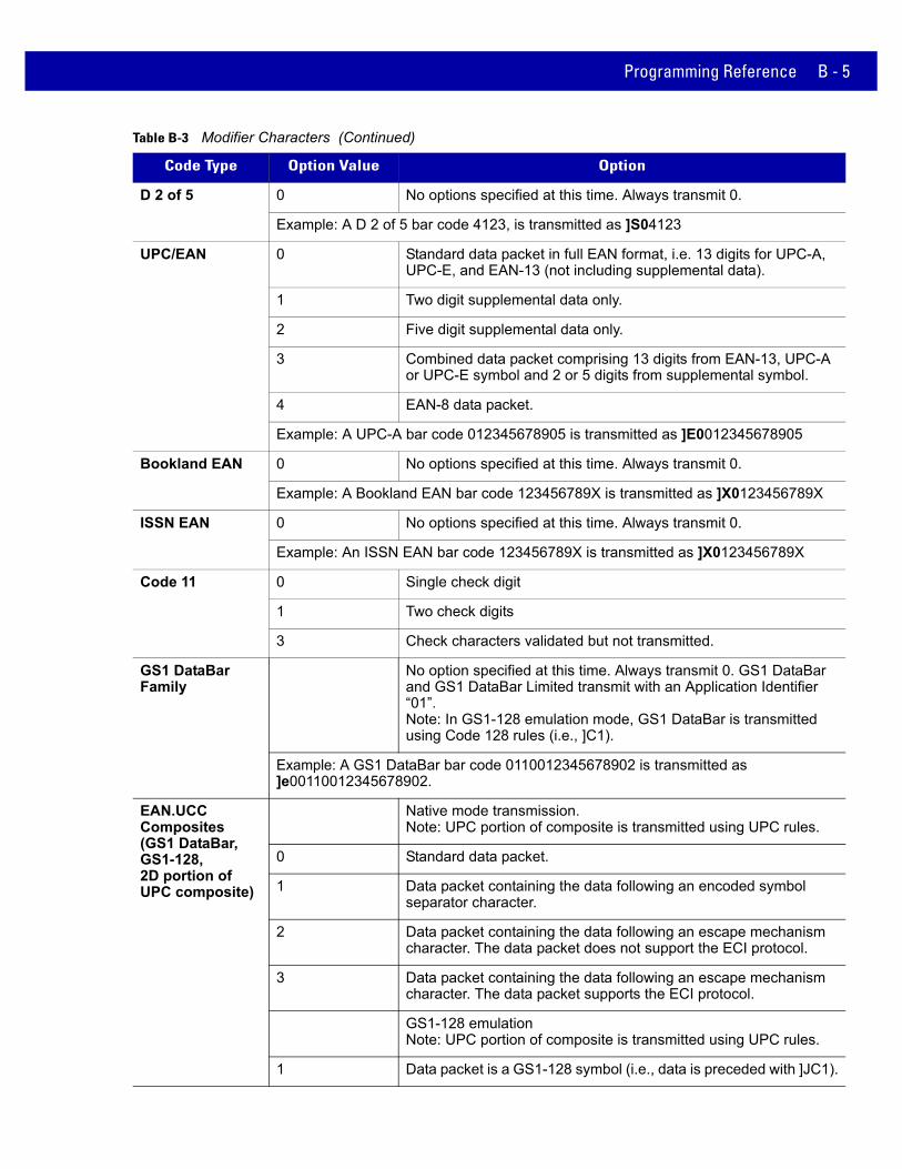
Programming Reference B - 5
D 2 of 5 0 No options specified at this time. Always transmit 0.
Example: A D 2 of 5 bar code 4123, is transmitted as ]S04123
UPC/EAN 0 Standard data packet in full EAN format, i.e. 13 digits for UPC-A, UPC-E, and EAN-13 (not including supplemental data).
1 Two digit supplemental data only.
2 Five digit supplemental data only.
3 Combined data packet comprising 13 digits from EAN-13, UPC-A or UPC-E symbol and 2 or 5 digits from supplemental symbol.
4 EAN-8 data packet.
Example: A UPC-A bar code 012345678905 is transmitted as ]E0012345678905
Bookland EAN 0 No options specified at this time. Always transmit 0.
Example: A Bookland EAN bar code 123456789X is transmitted as ]X0123456789X
ISSN EAN 0 No options specified at this time. Always transmit 0.
Example: An ISSN EAN bar code 123456789X is transmitted as ]X0123456789X
Code 11 0 Single check digit
1 Two check digits
3 Check characters validated but not transmitted.
GS1 DataBar Family
No option specified at this time. Always transmit 0. GS1 DataBar and GS1 DataBar Limited transmit with an Application Identifier “01”.Note: In GS1-128 emulation mode, GS1 DataBar is transmitted using Code 128 rules (i.e., ]C1).
Example: A GS1 DataBar bar code 0110012345678902 is transmitted as ]e00110012345678902.
EAN.UCC Composites (GS1 DataBar, GS1-128, 2D portion of UPC composite)
Native mode transmission.Note: UPC portion of composite is transmitted using UPC rules.
0 Standard data packet.
1 Data packet containing the data following an encoded symbol separator character.
2 Data packet containing the data following an escape mechanism character. The data packet does not support the ECI protocol.
3 Data packet containing the data following an escape mechanism character. The data packet supports the ECI protocol.
GS1-128 emulationNote: UPC portion of composite is transmitted using UPC rules.
1 Data packet is a GS1-128 symbol (i.e., data is preceded with ]JC1).
Table B-3 Modifier Characters (Continued)
Code Type Option Value Option

B - 6 MX101 PRODUCT REFERENCE GUIDE
PDF417, Micro PDF417
0 Reader set to conform to protocol defined in 1994 PDF417 symbology specifications. Note: When this option is transmitted, the receiver cannot reliably determine whether ECIs have been invoked or whether data byte 92DEC has been doubled in transmission.
1 Reader set to follow the ECI protocol (Extended Channel Interpretation). All data characters 92DEC are doubled.
2 Reader set for Basic Channel operation (no escape character transmission protocol). Data characters 92DEC are not doubled. Note: When scanners are set to this mode, unbuffered Macro symbols and symbols requiring the scanner to convey ECI escape sequences cannot be transmitted.
3 The bar code contains a GS1-128 symbol, and the first codeword is 903-907, 912, 914, 915.
4 The bar code contains a GS1-128 symbol, and the first codeword is in the range 908-909.
5 The bar code contains a GS1-128 symbol, and the first codeword is in the range 910-911.
Example: A PDF417 bar code ABCD, with no transmission protocol enabled, is transmitted as ]L2ABCD.
Data Matrix 0 ECC 000-140, not supported.
1 ECC 200.
2 ECC 200, FNC1 in first or fifth position.
3 ECC 200, FNC1 in second or sixth position.
4 ECC 200, ECI protocol implemented.
5 ECC 200, FNC1 in first or fifth position, ECI protocol implemented.
6 ECC 200, FNC1 in second or sixth position, ECI protocol implemented.
MaxiCode 0 Symbol in Mode 4 or 5.
1 Symbol in Mode 2 or 3.
2 Symbol in Mode 4 or 5, ECI protocol implemented.
3 Symbol in Mode 2 or 3, ECI protocol implemented in secondary message.
Table B-3 Modifier Characters (Continued)
Code Type Option Value Option

Programming Reference B - 7
QR Code 0 Model 1 symbol.
1 Model 2 / MicroQR symbol, ECI protocol not implemented.
2 Model 2 symbol, ECI protocol implemented.
3 Model 2 symbol, ECI protocol not implemented, FNC1 implied in first position.
4 Model 2 symbol, ECI protocol implemented, FNC1 implied in first position.
5 Model 2 symbol, ECI protocol not implemented, FNC1 implied in second position.
6 Model 2 symbol, ECI protocol implemented, FNC1 implied in second position.
Aztec 0 Aztec symbol.
C Aztec Rune symbol.
Table B-3 Modifier Characters (Continued)
Code Type Option Value Option

B - 8 MX101 PRODUCT REFERENCE GUIDE

APPENDIX C SAMPLE BAR CODES
Code 39
UPC/EAN
UPC-A, 100%
123ABC
0 12345 67890 5

C - 2 MX101 PRODUCT REFERENCE GUIDE
EAN-13, 100%
Code 128
Interleaved 2 of 5
3 4 5 6 7 8 9 0 1 2 3 4 0
1 2 3 4 5 6 7 8 9 0
12345678901231

Sample Bar Codes C - 3
GS1 DataBar-14
7612341562341
PDF417
Data Matrix
Maxicode
NOTE DataBar-14 must be enabled to read the bar code below (see GS1 DataBar on page 5-70).

C - 4 MX101 PRODUCT REFERENCE GUIDE
QR Code
US Postnet
UK Postal

APPENDIX D NUMERIC BAR CODES
Numeric Bar CodesFor parameters requiring specific numeric values, scan the appropriately numbered bar code(s).
0
1
2
3
4

D - 2 MX101 PRODUCT REFERENCE GUIDE
CancelTo correct an error or change a selection, scan the bar code below.
Numeric Bar Codes (continued)
5
6
7
8
9
Cancel

GLOSSARY
A
Aperture. The opening in an optical system defined by a lens or baffle that establishes the field of view.
API. An interface by means of which one software component communicates with or controls another. Usually used to refer to services provided by one software component to another, usually via software interrupts or function calls
Application Programming Interface. See API.
ASCII. American Standard Code for Information Interchange. A 7 bit-plus-parity code representing 128 letters, numerals, punctuation marks and control characters. It is a standard data transmission code in the U.S.
Autodiscrimination. The ability of an interface controller to determine the code type of a scanned bar code. After this determination is made, the information content is decoded.
B
Bar. The dark element in a printed bar code symbol.
Bar Code. A pattern of variable-width bars and spaces which represents numeric or alphanumeric data in machine-readable form. The general format of a bar code symbol consists of a leading margin, start character, data or message character, check character (if any), stop character, and trailing margin. Within this framework, each recognizable symbology uses its own unique format. See Symbology.
Bar Code Density. The number of characters represented per unit of measurement (e.g., characters per inch).
Bar Height. The dimension of a bar measured perpendicular to the bar width.
Bar Width. Thickness of a bar measured from the edge closest to the symbol start character to the trailing edge of the same bar.
BIOS. Basic Input Output System. A collection of ROM-based code with a standard API used to interface with standard PC hardware.

Glossary - 2 MX101 PRODUCT REFERENCE GUIDE
Bit. Binary digit. One bit is the basic unit of binary information. Generally, eight consecutive bits compose one byte of data. The pattern of 0 and 1 values within the byte determines its meaning.
Bits per Second (bps). Bits transmitted or received.
Boot or Boot-up. The process a computer goes through when it starts. During boot-up, the computer can run self-diagnostic tests and configure hardware and software.
BOOTP. A protocol for remote booting of diskless devices. Assigns an IP address to a machine and may specify a boot file. The client sends a bootp request as a broadcast to the bootp server port (67) and the bootp server responds using the bootp client port (68). The bootp server must have a table of all devices, associated MAC addresses and IP addresses.
bps. See Bits Per Second.
Byte. On an addressable boundary, eight adjacent binary digits (0 and 1) combined in a pattern to represent a specific character or numeric value. Bits are numbered from the right, 0 through 7, with bit 0 the low-order bit. One byte in memory is used to store one ASCII character.
C
CDRH. Center for Devices and Radiological Health. A federal agency responsible for regulating laser product safety. This agency specifies various laser operation classes based on power output during operation.
CDRH Class 1. This is the lowest power CDRH laser classification. This class is considered intrinsically safe, even if all laser output were directed into the eye's pupil. There are no special operating procedures for this class.
CDRH Class 2. No additional software mechanisms are needed to conform to this limit. Laser operation in this class poses no danger for unintentional direct human exposure.
Character. A pattern of bars and spaces which either directly represents data or indicates a control function, such as a number, letter, punctuation mark, or communications control contained in a message.
Character Set. Those characters available for encoding in a particular bar code symbology.
Check Digit. A digit used to verify a correct symbol decode. The scanner inserts the decoded data into an arithmetic formula and checks that the resulting number matches the encoded check digit. Check digits are required for UPC but are optional for other symbologies. Using check digits decreases the chance of substitution errors when a symbol is decoded.
Codabar. A discrete self-checking code with a character set consisting of digits 0 to 9 and six additional characters: ( - $ : / , +).
Code 128. A high density symbology which allows the controller to encode all 128 ASCII characters without adding extra symbol elements.
Code 3 of 9 (Code 39). A versatile and widely used alphanumeric bar code symbology with a set of 43 character types, including all uppercase letters, numerals from 0 to 9 and 7 special characters (- . / + % $ and space). The code name is derived from the fact that 3 of 9 elements representing a character are wide, while the remaining 6 are narrow.
Code 93. An industrial symbology compatible with Code 39 but offering a full character ASCII set and a higher coding density than Code 39.

Glossary - 3
Code Length. Number of data characters in a bar code between the start and stop characters, not including those characters.
Cold Boot. A cold boot restarts the mobile computer and erases all user stored records and entries.
COM port. Communication port; ports are identified by number, e.g., COM1, COM2.
Continuous Code. A bar code or symbol in which all spaces within the symbol are parts of characters. There are no intercharacter gaps in a continuous code. The absence of gaps allows for greater information density.
Cradle. A cradle is used for charging the terminal battery and for communicating with a host computer, and provides a storage place for the terminal when not in use.
D
Dead Zone. An area within a scanner's field of view, in which specular reflection may prevent a successful decode.
Decode. To recognize a bar code symbology (e.g., UPC/EAN) and then analyze the content of the specific bar code scanned.
Decode Algorithm. A decoding scheme that converts pulse widths into data representation of the letters or numbers encoded within a bar code symbol.
Decryption. Decryption is the decoding and unscrambling of received encrypted data. Also see, Encryption and Key.
Depth of Field. The range between minimum and maximum distances at which a scanner can read a symbol with a certain minimum element width.
Discrete 2 of 5. A binary bar code symbology representing each character by a group of five bars, two of which are wide. The location of wide bars in the group determines which character is encoded; spaces are insignificant. Only numeric characters (0 to 9) and START/STOP characters may be encoded.
Discrete Code. A bar code or symbol in which the spaces between characters (intercharacter gaps) are not part of the code.
DRAM. Dynamic random access memory.
E
EAN. European Article Number. This European/International version of the UPC provides its own coding format and symbology standards. Element dimensions are specified metrically. EAN is used primarily in retail.
Element. Generic term for a bar or space.
Encoded Area. Total linear dimension occupied by all characters of a code pattern, including start/stop characters and data.
ESD. Electro-Static Discharge

Glossary - 4 MX101 PRODUCT REFERENCE GUIDE
F
Flash Disk. An additional megabyte of non-volatile memory for storing application and configuration files.
Flash Memory. Flash memory is responsible for storing the system firmware and is non-volatile. If the system power is interrupted the data is not be lost.
FTP. See File Transfer Protocol.
H
Hard Reset. See Cold Boot.
Host Computer. A computer that serves other terminals in a network, providing such services as computation, database access, supervisory programs and network control.
Hz. Hertz; A unit of frequency equal to one cycle per second.
I
IDE. Intelligent drive electronics. Refers to the solid-state hard drive type.
IEC. International Electrotechnical Commission. This international agency regulates laser safety by specifying various laser operation classes based on power output during operation.
IEC60825-1 Class 1. This is the lowest power IEC laser classification. Conformity is ensured through a software restriction of 120 seconds of laser operation within any 1000 second window and an automatic laser shutdown if the scanner's oscillating mirror fails.
IEEE Address. See MAC Address.
Input/Output Ports. I/O ports are primarily dedicated to passing information into or out of the terminal’s memory. Series 9000 mobile computers include Serial and USB ports.
Intercharacter Gap. The space between two adjacent bar code characters in a discrete code.
Interleaved 2 of 5. A binary bar code symbology representing character pairs in groups of five bars and five interleaved spaces. Interleaving provides for greater information density. The location of wide elements (bar/spaces) within each group determines which characters are encoded. This continuous code type uses no intercharacter spaces. Only numeric (0 to 9) and START/STOP characters may be encoded.
Interleaved Bar Code. A bar code in which characters are paired together, using bars to represent the first character and the intervening spaces to represent the second.
Interleaved 2 of 5. A binary bar code symbology representing character pairs in groups of five bars and five interleaved spaces. Interleaving provides for greater information density. The location of wide elements (bar/spaces) within each group determines which characters are encoded. This continuous code type uses no intercharacter spaces. Only numeric (0 to 9) and START/STOP characters may be encoded.

Glossary - 5
I/O Ports. interface The connection between two devices, defined by common physical characteristics, signal characteristics, and signal meanings.
IOCTL. Input/Output Control.
IP Address. (Internet Protocol address) The address of a computer attached to an IP network. Every client and server station must have a unique IP address. A 32-bit address used by a computer on a IP network. Client workstations have either a permanent address or one that is dynamically assigned to them each session. IP addresses are written as four sets of numbers separated by periods; for example, 204.171.64.2.
IPX/SPX. Internet Package Exchange/Sequential Packet Exchange. A communications protocol for Novell. IPX is Novell’s Layer 3 protocol, similar to XNS and IP, and used in NetWare networks. SPX is Novell's version of the Xerox SPP protocol.
IS-95. Interim Standard 95. The EIA/TIA standard that governs the operation of CDMA cellular service. Versions include IS-95A and IS-95B. See CDMA.
K
Key. A key is the specific code used by the algorithm to encrypt or decrypt the data. Also see, Encryption and Decrypting.
L
LASER. Light Amplification by Stimulated Emission of Radiation.The laser is an intense light source. Light from a laser is all the same frequency, unlike the output of an incandescent bulb. Laser light is typically coherent and has a high energy density.
Laser Diode. A gallium-arsenide semiconductor type of laser connected to a power source to generate a laser beam. This laser type is a compact source of coherent light.
Laser Scanner. A type of bar code reader that uses a beam of laser light.
LCD. See Liquid Crystal Display.
LED Indicator. A semiconductor diode (LED - Light Emitting Diode) used as an indicator, often in digital displays. The semiconductor uses applied voltage to produce light of a certain frequency determined by the semiconductor's particular chemical composition.
Light Emitting Diode. See LED.
Liquid Crystal Display (LCD). A display that uses liquid crystal sealed between two glass plates. The crystals are excited by precise electrical charges, causing them to reflect light outside according to their bias. They use little electricity and react relatively quickly. They require external light to reflect their information to the user.

Glossary - 6 MX101 PRODUCT REFERENCE GUIDE
M
MIL. 1 mil = 1 thousandth of a meter.
Misread (Misdecode). A condition which occurs when the data output of a reader or interface controller does not agree with the data encoded within a bar code symbol.
N
Nominal. The exact (or ideal) intended value for a specified parameter. Tolerances are specified as positive and negative deviations from this value.
Nominal Size. Standard size for a bar code symbol. Most UPC/EAN codes are used over a range of magnifications (e.g., from 0.80 to 2.00 of nominal).
NVM. Non-Volatile Memory.
O
ODI. See Open Data-Link Interface.
Open Data-Link Interface (ODI). Novell’s driver specification for an interface between network hardware and higher-level protocols. It supports multiple protocols on a single NIC (Network Interface Controller). It is capable of understanding and translating any network information or request sent by any other ODI-compatible protocol into something a NetWare client can understand and process.
Open System Authentication. Open System authentication is a null authentication algorithm.
P
PAN . Personal area network. Using Bluetooth wireless technology, PANs enable devices to communicate wirelessly. Generally, a wireless PAN consists of a dynamic group of less than 255 devices that communicate within about a 33-foot range. Only devices within this limited area typically participate in the network.
Parameter. A variable that can have different values assigned to it.
PC Card. A plug-in expansion card for laptop computers and other devices, also called a PCMCIA card. PC Cards are 85.6mm long x 54 mm wide, and have a 68 pin connector. There are several different kinds:
• Type I; 3.3 mm high; use - RAM or Flash RAM
• Type II; 5 mm high; use - modems, LAN adaptors
• Type III; 10.5 high; use - Hard Disks
PCMCIA. Personal Computer Memory Card Interface Association. See PC Card.

Glossary - 7
Percent Decode. The average probability that a single scan of a bar code would result in a successful decode. In a well-designed bar code scanning system, that probability should approach near 100%.
PING. (Packet Internet Groper) An Internet utility used to determine whether a particular IP address is online. It is used to test and debug a network by sending out a packet and waiting for a response.
Presentation Mode. Typically used when the digital scanner sits on a countertop or is mounted on a wall, in this mode, the digital scanner operates in continuous (constant-on) mode, where it automatically decodes a bar code presented in its field of view.
Print Contrast Signal (PCS). Measurement of the contrast (brightness difference) between the bars and spaces of a symbol. A minimum PCS value is needed for a bar code symbol to be scannable. PCS = (RL - RD) / RL, where RL is the reflectance factor of the background and RD the reflectance factor of the dark bars.
Programming Mode. The state in which a scanner is configured for parameter values. See Scanning Mode.
Q
Quiet Zone. A clear space, containing no dark marks, which precedes the start character of a bar code symbol and follows the stop character.
QWERTY. A standard keyboard commonly used on North American and some European PC keyboards. “QWERTY” refers to the arrangement of keys on the left side of the third row of keys.
R
RAM. Random Access Memory. Data in RAM can be accessed in random order, and quickly written and read.
Reflectance. Amount of light returned from an illuminated surface.
Resolution. The narrowest element dimension which is distinguished by a particular reading device or printed with a particular device or method.
RF. Radio Frequency.
ROM. Read-Only Memory. Data stored in ROM cannot be changed or removed.
Router. A device that connects networks and supports the required protocols for packet filtering. Routers are typically used to extend the range of cabling and to organize the topology of a network into subnets. See Subnet.

Glossary - 8 MX101 PRODUCT REFERENCE GUIDE
S
Scan Area. Area intended to contain a symbol.
Scanner. An electronic device used to scan bar code symbols and produce a digitized pattern that corresponds to the bars and spaces of the symbol. Its three main components are: 1) Light source (laser or photoelectric cell) - illuminates a bar code,; 2) Photodetector - registers the difference in reflected light (more light reflected from spaces); 3) Signal conditioning circuit - transforms optical detector output into a digitized bar pattern.
Scanning Mode. The scanner is energized, programmed and ready to read a bar code.
Scanning Sequence. A method of programming or configuring parameters for a bar code reading system by scanning bar code menus.
SDK. Software Development Kit
Self-Checking Code. A symbology that uses a checking algorithm to detect encoding errors within the characters of a bar code symbol.
Shared Key. Shared Key authentication is an algorithm where both the AP and the MU share an authentication key.
SHIP. Symbol Host Interface Program.
SID. System Identification code. An identifier issued by the FCC for each market. It is also broadcast by the cellular carriers to allow cellular devices to distinguish between the home and roaming service.
Soft Reset. See Warm Boot.
Space. The lighter element of a bar code formed by the background between bars.
Specular Reflection. The mirror-like direct reflection of light from a surface, which can cause difficulty decoding a bar code.
Standard Trigger Mode. The digital scanner uses this mode when lifted off the counter or removed from the wall mount. In this mode, aim the digital scanner at a bar code and pull the trigger to decode.
Start/Stop Character. A pattern of bars and spaces that provides the scanner with start and stop reading instructions and scanning direction. The start and stop characters are normally to the left and right margins of a horizontal code.
STEP. Symbol Terminal Enabler Program.
Subnet. A subset of nodes on a network that are serviced by the same router. See Router.
Subnet Mask. A 32-bit number used to separate the network and host sections of an IP address. A custom subnet mask subdivides an IP network into smaller subsections. The mask is a binary pattern that is matched up with the IP address to turn part of the host ID address field into a field for subnets. Default is often 255.255.255.0.
Substrate. A foundation material on which a substance or image is placed.
SVTP. Symbol Virtual Terminal Program.
Symbol. A scannable unit that encodes data within the conventions of a certain symbology, usually including start/stop characters, quiet zones, data characters and check characters.

Glossary - 9
Symbol Aspect Ratio. The ratio of symbol height to symbol width.
Symbol Height. The distance between the outside edges of the quiet zones of the first row and the last row.
Symbol Length. Length of symbol measured from the beginning of the quiet zone (margin) adjacent to the start character to the end of the quiet zone (margin) adjacent to a stop character.
Symbology. The structural rules and conventions for representing data within a particular bar code type (e.g. UPC/EAN, Code 39, PDF417, etc.).
T
TCP/IP. (Transmission Control Protocol/Internet Protocol) A communications protocol used to internetwork dissimilar systems. This standard is the protocol of the Internet and has become the global standard for communications. TCP provides transport functions, which ensures that the total amount of bytes sent is received correctly at the other end. UDP is an alternate transport that does not guarantee delivery. It is widely used for real-time voice and video transmissions where erroneous packets are not retransmitted. IP provides the routing mechanism. TCP/IP is a routable protocol, which means that all messages contain not only the address of the destination station, but the address of a destination network. This allows TCP/IP messages to be sent to multiple networks within an organization or around the world, hence its use in the worldwide Internet. Every client and server in a TCP/IP network requires an IP address, which is either permanently assigned or dynamically assigned at startup.
Telnet. A terminal emulation protocol commonly used on the Internet and TCP/IP-based networks. It allows a user at a terminal or computer to log onto a remote device and run a program.
Terminal Emulation. A “terminal emulation” emulates a character-based mainframe session on a remote non-mainframe terminal, including all display features, commands and function keys. The VC5000 Series supports Terminal Emulations in 3270, 5250 and VT220.
Terminate and Stay Resident (TSR). A program under DOS that ends its foreground execution to remain resident in memory to service hardware/software interrupts, providing background operation. It remains in memory and may provide services on behalf of other DOS programs.
TFTP. (Trivial File Transfer Protocol) A version of the TCP/IP FTP (File Transfer Protocol) protocol that has no directory or password capability. It is the protocol used for upgrading firmware, downloading software and remote booting of diskless devices.
Tolerance. Allowable deviation from the nominal bar or space width.
Transmission Control Protocol/Internet Protocol. See TCP/IP.
Trivial File Transfer Protocol. See TFTP.
TSR. See Terminate and Stay Resident.
U
UDP. User Datagram Protocol. A protocol within the IP protocol suite that is used in place of TCP when a reliable delivery is not required. For example, UDP is used for real-time audio and video traffic where lost packets are simply

Glossary - 10 MX101 PRODUCT REFERENCE GUIDE
ignored, because there is no time to retransmit. If UDP is used and a reliable delivery is required, packet sequence checking and error notification must be written into the applications.
UPC. Universal Product Code. A relatively complex numeric symbology. Each character consists of two bars and two spaces, each of which is any of four widths. The standard symbology for retail food packages in the United States.
V
Visible Laser Diode (VLD). A solid state device which produces visible laser light.
W
Warm Boot. A warm boot restarts the mobile computer by closing all running programs. All data that is not saved to flash memory is lost.

INDEX
Numerics2D bar codes
aztec . . . . . . . . . . . . . . . . . . . . . . . . . . . . . . . . . 5-83aztec inverse . . . . . . . . . . . . . . . . . . . . . . . . . . 5-83code 128 emulation . . . . . . . . . . . . . . . . . . . . . 5-78data matrix . . . . . . . . . . . . . . . . . . . . . . . . . . . . 5-79data matrix inverse . . . . . . . . . . . . . . . . . . . . . . 5-79maxicode . . . . . . . . . . . . . . . . . . . . . . . . . . . . . 5-81microPDF417 . . . . . . . . . . . . . . . . . . . . . . . . . . 5-77microQR . . . . . . . . . . . . . . . . . . . . . . . . . . . . . . 5-82PDF417 . . . . . . . . . . . . . . . . . . . . . . . . . . . . . . 5-77QR code . . . . . . . . . . . . . . . . . . . . . . . . . . . . . . 5-81QR inverse . . . . . . . . . . . . . . . . . . . . . . . . . . . . 5-82
AADF . . . . . . . . . . . . . . . . . . . . . . . . . . . . . . . . . . . . . . 7-1advanced data formatting . . . . . . . . . . . . . . . . . . . . . 7-1aiming options
decode aiming pattern . . . . . . . . . . . . . . . . . . . 4-19aiming pattern
enabling . . . . . . . . . . . . . . . . . . . . . . . . . . . . . . 4-19
Bbar codes
abort macro PDF entry . . . . . . . . . . . . . . . . . . . 5-91Australia post . . . . . . . . . . . . . . . . . . . . . . . . . . 5-66Australia post format . . . . . . . . . . . . . . . . . . . . . 5-67aztec . . . . . . . . . . . . . . . . . . . . . . . . . . . . . . . . . 5-83aztec inverse . . . . . . . . . . . . . . . . . . . . . . . . . . 5-83beep after good decode . . . . . . . . . . . . . . . . . . . 4-7beeper duration . . . . . . . . . . . . . . . . . . . . . . . . 4-10beeper tone . . . . . . . . . . . . . . . . . . . . . . . . . . . . 4-8beeper volume . . . . . . . . . . . . . . . . . . . . . . . . . . 4-9bookland EAN . . . . . . . . . . . . . . . . . . . . . . . . . . 5-11
bookland ISBN . . . . . . . . . . . . . . . . . . . . . . . . . 5-12buffering . . . . . . . . . . . . . . . . . . . . . . . . . . . . . . 5-36cancel . . . . . . . . . . . . . . . . . . . . . . . . . . . . . . . . . D-2Chinese 2 of 5 . . . . . . . . . . . . . . . . . . . . . . . . . . 5-57codabar . . . . . . . . . . . . . . . . . . . . . . . . . . . . . . . 5-50codabar CLSI editing . . . . . . . . . . . . . . . . . . . . . 5-52codabar lengths . . . . . . . . . . . . . . . . . . . . . . . . . 5-50codabar NOTIS editing . . . . . . . . . . . . . . . . . . . 5-52codabar start and stop characters . . . . . . . . . . . 5-53code 11 . . . . . . . . . . . . . . . . . . . . . . . . . . . . . . . 5-40code 11 lengths . . . . . . . . . . . . . . . . . . . . . . . . . 5-40code 128 . . . . . . . . . . . . . . . . . . . . . . . . . . . . . . 5-26code 128 emulation . . . . . . . . . . . . . . . . . . . . . . 5-78code 128 lengths . . . . . . . . . . . . . . . . . . . . . . . . 5-26code 39 . . . . . . . . . . . . . . . . . . . . . . . . . . . . . . . 5-31
transmit buffer . . . . . . . . . . . . . . . . . . . . . . . 5-37code 39 check digit verification . . . . . . . . . . . . . 5-34code 39 full ASCII . . . . . . . . . . . . . . . . . . . . . . . 5-35code 39 lengths . . . . . . . . . . . . . . . . . . . . . . . . . 5-33code 39 transmit check digit . . . . . . . . . . . . . . . 5-34code 93 . . . . . . . . . . . . . . . . . . . . . . . . . . . . . . . 5-38code 93 lengths . . . . . . . . . . . . . . . . . . . . . . . . . 5-38composite CC-A/B . . . . . . . . . . . . . . . . . . . . . . . 5-74composite CC-C . . . . . . . . . . . . . . . . . . . . . . . . 5-74composite TLC-39 . . . . . . . . . . . . . . . . . . . . . . . 5-75convert GS1 databar to UPC/EAN . . . . . . . . . . 5-73convert UPC-E to UPC-A . . . . . . . . . . . . . . . . . 5-22convert UPC-E1 to UPC-A . . . . . . . . . . . . . . . . 5-22coupon report . . . . . . . . . . . . . . . . . . . . . . . . . . 5-24data matrix . . . . . . . . . . . . . . . . . . . . . . . . . . . . . 5-79data matrix inverse . . . . . . . . . . . . . . . . . . . . . . 5-79decode aiming pattern . . . . . . . . . . . . . . . . . . . . 4-19decode mirror images . . . . . . . . . . . . . . . . . . . . 5-80decode session timeout . . . . . . . . . . . . . . . . . . . 4-11disable all code types . . . . . . . . . . . . . . . . . . . . . 5-8discrete 2 of 5 . . . . . . . . . . . . . . . . . . . . . . . . . . 5-48
lengths . . . . . . . . . . . . . . . . . . . . . . . . . . . . 5-49

Index - 2 MX101 PRODUCT REFERENCE GUIDE
EAN zero extend . . . . . . . . . . . . . . . . . . . . . . . . 5-23EAN-13/JAN-13 . . . . . . . . . . . . . . . . . . . . . . . . 5-11EAN-8/JAN-8 . . . . . . . . . . . . . . . . . . . . . . . . . . 5-10escape characters . . . . . . . . . . . . . . . . . . . . . . . 5-90flush macro buffer . . . . . . . . . . . . . . . . . . . . . . . 5-91fuzzy 1D processing . . . . . . . . . . . . . . . . . . . . . 4-16GS1 databar . . . . . . . . . . . . . . . . . . . . . . . . . . . 5-70GS1 databar expanded . . . . . . . . . . . . . . . . . . . 5-73GS1 databar limited . . . . . . . . . . . . . . . . . . . . . 5-71GS1 databar limited security level . . . . . . . . . . 5-72GS1-128 . . . . . . . . . . . . . . . . . . . . . . . . . . . . . . 5-27I 2 of 5 check digit verification . . . . . . . . . . . . . . 5-46I 2 of 5 convert to EAN-13 . . . . . . . . . . . . . . . . . 5-47I 2 of 5 transmit check digit . . . . . . . . . . . . . . . . 5-46illumination . . . . . . . . . . . . . . . . . . . . . . . . . . . . 4-18illumination brightness . . . . . . . . . . . . . . . . . . . 4-18interleaved 2 of 5 . . . . . . . . . . . . . . . . . . . . . . . 5-44
convert to EAN-13 . . . . . . . . . . . . . . . . . . . 5-47lengths . . . . . . . . . . . . . . . . . . . . . . . . . . . . 5-44
inverse 1D . . . . . . . . . . . . . . . . . . . . . . . . . . . . . 5-62ISBT 128 . . . . . . . . . . . . . . . . . . . . . . . . . . . . . . 5-28ISBT concatenation . . . . . . . . . . . . . . . . . .5-29, 5-30ISBT concatenation redundancy . . . . . . . . . . . . 5-30ISSN EAN . . . . . . . . . . . . . . . . . . . . . . . . . . . . . 5-25Japan postal . . . . . . . . . . . . . . . . . . . . . . . . . . . 5-65Korean 3 of 5 . . . . . . . . . . . . . . . . . . . . . . . . . . 5-61lock/unlock parameter scanning . . . . . . . . . . . . . 4-6macro PDF transmit / decode mode symbols . . 5-89matrix 2 of 5 . . . . . . . . . . . . . . . . . . . . . . . . . . . 5-58matrix 2 of 5 check digit . . . . . . . . . . . . . . . . . . 5-60matrix 2 of 5 lengths . . . . . . . . . . . . . . . . . . . . . 5-59maxicode . . . . . . . . . . . . . . . . . . . . . . . . . . . . . . 5-81microPDF417 . . . . . . . . . . . . . . . . . . . . . . . . . . 5-77microQR . . . . . . . . . . . . . . . . . . . . . . . . . . . . . . 5-82mirrored image . . . . . . . . . . . . . . . . . . . . . . . . . 4-16mobile phone/display mode . . . . . . . . . . . . . . . 4-17motion detect range . . . . . . . . . . . . . . . . . . . . . 4-13MSI . . . . . . . . . . . . . . . . . . . . . . . . . . . . . . . . . . 5-54MSI check digit algorithm . . . . . . . . . . . . . . . . . 5-57MSI check digits . . . . . . . . . . . . . . . . . . . . . . . . 5-56MSI lengths . . . . . . . . . . . . . . . . . . . . . . . . . . . . 5-54MSI transmit check digit . . . . . . . . . . . . . . . . . . 5-56Netherlands KIX code . . . . . . . . . . . . . . . . . . . . 5-68numeric bar codes . . . . . . . . . . . . . . . . . . . . . . . D-2parameter bar code scanning . . . . . . . . . . . . . . . 4-5PDF417 . . . . . . . . . . . . . . . . . . . . . . . . . . . . . . . 5-77postal . . . . . . . . . . . . . . . . . . . . . . . . . . . . . . . . 5-63prefix/suffix values . . . . . . . . . . . . . . . . . . . . . . 4-21presentation mode field of view . . . . . . . . . . . . 4-15QR code . . . . . . . . . . . . . . . . . . . . . . . . . . . . . . 5-81QR inverse . . . . . . . . . . . . . . . . . . . . . . . . . . . . 5-82range restrict . . . . . . . . . . . . . . . . . . . . . . . . . . . 4-14report scan engine manufacturing information . 4-24report scanner manufacturing information . . . . 4-24
report software version . . . . . . . . . . . . . . . 4-24, 9-3samples . . . . . . . . . . . . . . . . . . . . . . . . . . . . . . . .C-1scan data options . . . . . . . . . . . . . . . . . . . . . . . . 4-22set defaults . . . . . . . . . . . . . . . . . . . . . . . . . . . . . 4-4supplementals . . . . . . . . . . . . . . . . . . . . . . . . . . 5-13suppress power-up beeps . . . . . . . . . . . . . . . . . 4-10symbologies
default table . . . . . . . . . . . . . . . . . . . . . . . . . . 5-2timeout between decodes . . . . . . . . . . . . . . . . . 4-12timeout between decodes, different symbols . . . 4-12transmit code ID character . . . . . . . . . . . . . . . . . 4-20transmit macro PDF control header . . . . . . . . . . 5-90transmit matrix 2 of 5 check digit . . . . . . . . . . . . 5-60transmit UK postal check digit . . . . . . . . . . . . . . 5-65transmit US postal check digit . . . . . . . . . . . . . . 5-64trigger modes . . . . . . . . . . . . . . . . . . . . . . . . . . . 4-11UCC coupon extended code . . . . . . . . . . . . . . . 5-23UK postal . . . . . . . . . . . . . . . . . . . . . . . . . . . . . . 5-64UPC composite mode . . . . . . . . . . . . . . . . . . . . 5-75UPC/EAN
coupon code . . . . . . . . . . . . . . . . . . . . . . . . 5-23supp redundancy . . . . . . . . . . . . . . . . . . . . . 5-17supplemental redundancy . . . . . . . . . . . . . . 5-16
UPC/EAN/JANsupplemental AIM ID format . . . . . . . . . . . . 5-17supplemental redundancy . . . . . . . . . . . . . . 5-16
UPC-A . . . . . . . . . . . . . . . . . . . . . . . . . . . . . . . . . 5-9UPC-A preamble . . . . . . . . . . . . . . . . . . . . . . . . 5-19UPC-A/E/E1 check digit . . . . . . . . . . . . . . 5-18, 5-19UPC-E . . . . . . . . . . . . . . . . . . . . . . . . . . . . . . . . . 5-9UPC-E preamble . . . . . . . . . . . . . . . . . . . . . . . . 5-20UPC-E1 . . . . . . . . . . . . . . . . . . . . . . . . . . . . . . . 5-10UPU FICS postal . . . . . . . . . . . . . . . . . . . . . . . . 5-69US planet . . . . . . . . . . . . . . . . . . . . . . . . . . . . . . 5-63US postnet . . . . . . . . . . . . . . . . . . . . . . . . . . . . . 5-63USB
host parameters . . . . . . . . . . . . . . . . . . . . . . 3-2IBM specification version . . . . . . . . . . . . . . . . 3-3
USPS 4CB/One Code/Intelligent Mail . . . . . . . . 5-68validate concatenated parameter bar codes . . . 4-17
beeperbeep after good decode . . . . . . . . . . . . . . . . . . . . 4-7duration . . . . . . . . . . . . . . . . . . . . . . . . . . . . . . . 4-10setting tone . . . . . . . . . . . . . . . . . . . . . . . . . . . . . 4-8setting volume . . . . . . . . . . . . . . . . . . . . . . . . . . . 4-9suppress power-up beeps . . . . . . . . . . . . . . . . . 4-10
beeper definitions . . . . . . . . . . . . . . . . . . . . . . . . . . . . 2-2bullets . . . . . . . . . . . . . . . . . . . . . . . . . . . . . . . . . . . . . . .x
Ccables
signal descriptions . . . . . . . . . . . . . . . . . . . . . . . . 9-4Chinese 2 of 5 bar codes . . . . . . . . . . . . . . . . . . . . . 5-57

Index - 3
codabar bar codesCLSI editing . . . . . . . . . . . . . . . . . . . . . . . . . . . 5-52codabar . . . . . . . . . . . . . . . . . . . . . . . . . . . . . . . 5-50lengths . . . . . . . . . . . . . . . . . . . . . . . . . . . . . . . 5-50NOTIS editing . . . . . . . . . . . . . . . . . . . . . . . . . . 5-52start and stop characters . . . . . . . . . . . . . . . . . 5-53
code 11 bar codescode 11 . . . . . . . . . . . . . . . . . . . . . . . . . . . . . . . 5-40lengths . . . . . . . . . . . . . . . . . . . . . . . . . . . . . . . 5-40
code 128 bar codescode 128 . . . . . . . . . . . . . . . . . . . . . . . . . . . . . . 5-26GS1-128 . . . . . . . . . . . . . . . . . . . . . . . . . . . . . . 5-27ISBT 128 . . . . . . . . . . . . . . . . . . . . . . . . . . . . . . 5-28ISBT concatenation . . . . . . . . . . . . . . . . . 5-29, 5-30ISBT concatenation redundancy . . . . . . . . . . . 5-30lengths . . . . . . . . . . . . . . . . . . . . . . . . . . . . . . . 5-26
code 128 emulation bar codes . . . . . . . . . . . . . . . . 5-78code 39 bar codes
buffering . . . . . . . . . . . . . . . . . . . . . . . . . . . . . . 5-36check digit verification . . . . . . . . . . . . . . . . . . . 5-34code 39 . . . . . . . . . . . . . . . . . . . . . . . . . . . . . . . 5-31full ASCII . . . . . . . . . . . . . . . . . . . . . . . . . . . . . . 5-35lengths . . . . . . . . . . . . . . . . . . . . . . . . . . . . . . . 5-33transmit check digit . . . . . . . . . . . . . . . . . . . . . . 5-34
code 93 bar codescode 93 . . . . . . . . . . . . . . . . . . . . . . . . . . . . . . . 5-38lengths . . . . . . . . . . . . . . . . . . . . . . . . . . . . . . . 5-38
code ID character . . . . . . . . . . . . . . . . . . . . . . . . . . 4-20code identifiers
AIM code IDs . . . . . . . . . . . . . . . . . . . . . . . . . . . B-3modifier characters . . . . . . . . . . . . . . . . . . . . . . . B-4Symbol . . . . . . . . . . . . . . . . . . . . . . . . . . . . . . . . B-1
composite bar codescomposite CC-A/B . . . . . . . . . . . . . . . . . . . . . . 5-74composite CC-C . . . . . . . . . . . . . . . . . . . . . . . . 5-74composite TLC-39 . . . . . . . . . . . . . . . . . . . . . . 5-75UPC composite mode . . . . . . . . . . . . . . . . . . . . 5-75
conventionsnotational . . . . . . . . . . . . . . . . . . . . . . . . . . . . . . . . x
CSSinstallation . . . . . . . . . . . . . . . . . . . . . . . . . . . . . . 8-1
Ddata matrix bar codes . . . . . . . . . . . . . . . . . . . . . . . 5-79decode ranges . . . . . . . . . . . . . . . . . . . . . . . . . . . . . 2-3default parameters
standard default table . . . . . . . . . . . . . . . . . . . . . A-1symbologies . . . . . . . . . . . . . . . . . . . . . . . . . . . . 5-2user preferences . . . . . . . . . . . . . . . . . . . . . . 3-1, 4-2
discrete 2 of 5 bar codesdiscrete 2 of 5 . . . . . . . . . . . . . . . . . . . . . . . . . . 5-48
Eexposure options
illumination . . . . . . . . . . . . . . . . . . . . . . . . . . . . 4-18presentation mode field of view . . . . . . . . . . . . . 4-15
Fferrite placement . . . . . . . . . . . . . . . . . . . . . . . . . . . . 8-3
GGS1 databar . . . . . . . . . . . . . . . . . . . . . . . . . . . . . . 5-70
convert GS1 databar to UPC/EAN . . . . . . . . . . 5-73
Iillumination . . . . . . . . . . . . . . . . . . . . . . . . . . . . . . . . 4-18
brightness . . . . . . . . . . . . . . . . . . . . . . . . . . . . . 4-18indicators . . . . . . . . . . . . . . . . . . . . . . . . . . . . . . . . . . 2-2interleaved 2 of 5 bar codes
check digit verification . . . . . . . . . . . . . . . . . . . . 5-46convert to EAN-13 . . . . . . . . . . . . . . . . . . . . . . . 5-47transmit check digit . . . . . . . . . . . . . . . . . . . . . . 5-46
KKorean 3 of 5 bar codes . . . . . . . . . . . . . . . . . . . . . 5-61
LLED definitions . . . . . . . . . . . . . . . . . . . . . . . . . . . . . . 2-2
Mmacro PDF . . . . . . . . . . . . . . . . . . . . . . . . . . . . . . . . 5-88
abort PDF entry . . . . . . . . . . . . . . . . . . . . . . . . . 5-91escape characters . . . . . . . . . . . . . . . . . . . . . . . 5-90flush buffer . . . . . . . . . . . . . . . . . . . . . . . . . . . . . 5-91macro PDF transmit / decode mode symbols . . 5-89transmit macro PDF control header . . . . . . . . . 5-90user indications . . . . . . . . . . . . . . . . . . . . . . . . . 5-88
maintenance . . . . . . . . . . . . . . . . . . . . . . . . . . . . . . . 9-1matrix 2 of 5 bar codes . . . . . . . . . . . . . . . . . . . . . . 5-58
check digit . . . . . . . . . . . . . . . . . . . . . . . . . . . . . 5-60lengths . . . . . . . . . . . . . . . . . . . . . . . . . . . . . . . . 5-59transmit check digit . . . . . . . . . . . . . . . . . . . . . . 5-60
maxicode bar codes . . . . . . . . . . . . . . . . . . . . . . . . . 5-81microPDF417 bar codes . . . . . . . . . . . . . . . . . . . . . 5-77MSI bar codes
check digit algorithm . . . . . . . . . . . . . . . . . . . . . 5-57check digits . . . . . . . . . . . . . . . . . . . . . . . . . . . . 5-56lengths . . . . . . . . . . . . . . . . . . . . . . . . . . . . . . . . 5-54MSI . . . . . . . . . . . . . . . . . . . . . . . . . . . . . . . . . . 5-54
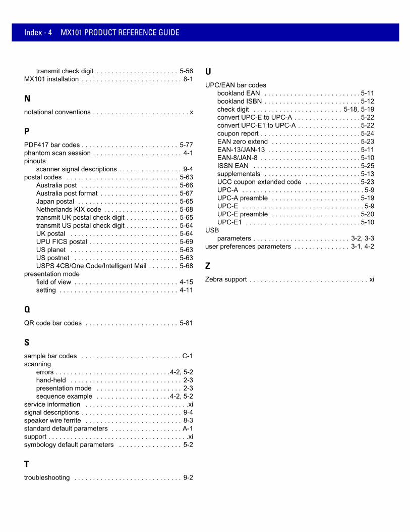
Index - 4 MX101 PRODUCT REFERENCE GUIDE
transmit check digit . . . . . . . . . . . . . . . . . . . . . . 5-56MX101 installation . . . . . . . . . . . . . . . . . . . . . . . . . . . 8-1
Nnotational conventions . . . . . . . . . . . . . . . . . . . . . . . . . . x
PPDF417 bar codes . . . . . . . . . . . . . . . . . . . . . . . . . . 5-77phantom scan session . . . . . . . . . . . . . . . . . . . . . . . . 4-1pinouts
scanner signal descriptions . . . . . . . . . . . . . . . . . 9-4postal codes . . . . . . . . . . . . . . . . . . . . . . . . . . . . . . 5-63
Australia post . . . . . . . . . . . . . . . . . . . . . . . . . . 5-66Australia post format . . . . . . . . . . . . . . . . . . . . . 5-67Japan postal . . . . . . . . . . . . . . . . . . . . . . . . . . . 5-65Netherlands KIX code . . . . . . . . . . . . . . . . . . . . 5-68transmit UK postal check digit . . . . . . . . . . . . . . 5-65transmit US postal check digit . . . . . . . . . . . . . . 5-64UK postal . . . . . . . . . . . . . . . . . . . . . . . . . . . . . 5-64UPU FICS postal . . . . . . . . . . . . . . . . . . . . . . . . 5-69US planet . . . . . . . . . . . . . . . . . . . . . . . . . . . . . 5-63US postnet . . . . . . . . . . . . . . . . . . . . . . . . . . . . 5-63USPS 4CB/One Code/Intelligent Mail . . . . . . . . 5-68
presentation modefield of view . . . . . . . . . . . . . . . . . . . . . . . . . . . . 4-15setting . . . . . . . . . . . . . . . . . . . . . . . . . . . . . . . . 4-11
QQR code bar codes . . . . . . . . . . . . . . . . . . . . . . . . . 5-81
Ssample bar codes . . . . . . . . . . . . . . . . . . . . . . . . . . . C-1scanning
errors . . . . . . . . . . . . . . . . . . . . . . . . . . . . . . .4-2, 5-2hand-held . . . . . . . . . . . . . . . . . . . . . . . . . . . . . . 2-3presentation mode . . . . . . . . . . . . . . . . . . . . . . . 2-3sequence example . . . . . . . . . . . . . . . . . . . .4-2, 5-2
service information . . . . . . . . . . . . . . . . . . . . . . . . . . . .xisignal descriptions . . . . . . . . . . . . . . . . . . . . . . . . . . . 9-4speaker wire ferrite . . . . . . . . . . . . . . . . . . . . . . . . . . 8-3standard default parameters . . . . . . . . . . . . . . . . . . . A-1support . . . . . . . . . . . . . . . . . . . . . . . . . . . . . . . . . . . . . .xisymbology default parameters . . . . . . . . . . . . . . . . . 5-2
Ttroubleshooting . . . . . . . . . . . . . . . . . . . . . . . . . . . . . 9-2
UUPC/EAN bar codes
bookland EAN . . . . . . . . . . . . . . . . . . . . . . . . . . 5-11bookland ISBN . . . . . . . . . . . . . . . . . . . . . . . . . . 5-12check digit . . . . . . . . . . . . . . . . . . . . . . . . 5-18, 5-19convert UPC-E to UPC-A . . . . . . . . . . . . . . . . . . 5-22convert UPC-E1 to UPC-A . . . . . . . . . . . . . . . . . 5-22coupon report . . . . . . . . . . . . . . . . . . . . . . . . . . . 5-24EAN zero extend . . . . . . . . . . . . . . . . . . . . . . . . 5-23EAN-13/JAN-13 . . . . . . . . . . . . . . . . . . . . . . . . . 5-11EAN-8/JAN-8 . . . . . . . . . . . . . . . . . . . . . . . . . . . 5-10ISSN EAN . . . . . . . . . . . . . . . . . . . . . . . . . . . . . 5-25supplementals . . . . . . . . . . . . . . . . . . . . . . . . . . 5-13UCC coupon extended code . . . . . . . . . . . . . . . 5-23UPC-A . . . . . . . . . . . . . . . . . . . . . . . . . . . . . . . . . 5-9UPC-A preamble . . . . . . . . . . . . . . . . . . . . . . . . 5-19UPC-E . . . . . . . . . . . . . . . . . . . . . . . . . . . . . . . . . 5-9UPC-E preamble . . . . . . . . . . . . . . . . . . . . . . . . 5-20UPC-E1 . . . . . . . . . . . . . . . . . . . . . . . . . . . . . . . 5-10
USBparameters . . . . . . . . . . . . . . . . . . . . . . . . . . 3-2, 3-3
user preferences parameters . . . . . . . . . . . . . . . 3-1, 4-2
ZZebra support . . . . . . . . . . . . . . . . . . . . . . . . . . . . . . . . xi

Tell Us What You Think...We’d like to know what you think about this Manual. Please take a moment to fill out this questionnaire and fax this form to: (631) 627-7184, or mail to:
Zebra Technologies CorporationLincolnshire, IL U.S.A. Attention: Data Capture Solutions
Technical Publications Manager
Manual Title:___________________________________________(please include revision level)
How familiar were you with this product before using this manual?
Did this manual meet your needs? If not, please explain.________________________________________________________________________________________________________________________________________________________________________________________________________________________________________________________________________________________________________________________________________________________
What topics need to be added to the index, if applicable? ________________________________________________________________________________________________________________________________________________________________________________________________________________________________________________________________________________________________________________________________________________________
What topics do you feel need to be better discussed? Please be specific.________________________________________________________________________________________________________________________________________________________________________________________________________________________________________________________________________________________________________________________________________________________
What can we do to further improve our manuals?________________________________________________________________________________________________________________________________________________________________________________________________________________________________________________________________________________________________________________________________________________________
important If you need product support, please call the appropriate customer support number provided. Unfortunately, we cannot provide customer support at the fax number above.
Very familiar Slightly familiar Not at all familiar
Thank you for your input—We value your comments.


72E-171320-04 Revision A - March 2015
Zebra Technologies CorporationLincolnshire, IL U.S.A.http://www.zebra.com
Zebra and the Zebra head graphic are registered trademarks of ZIH Corp. The Symbol logo is a registered trademark of Symbol Technologies, Inc., a Zebra Technologies company.
© 2015 Symbol Technologies, Inc.