Embed Size (px)
Citation preview
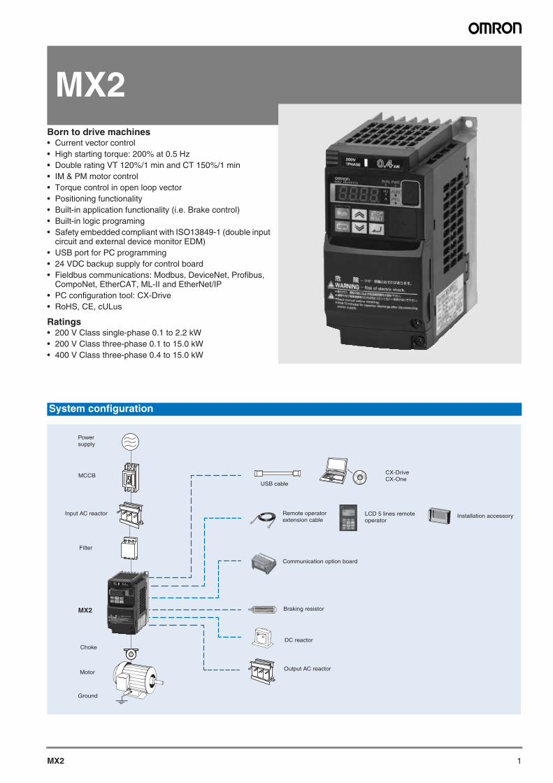
1MX2
MX2Born to drive machines• Current vector control• High starting torque: 200% at 0.5 Hz• Double rating VT 120%/1 min and CT 150%/1 min• IM & PM motor control• Torque control in open loop vector• Positioning functionality• Built-in application functionality (i.e. Brake control)• Built-in logic programing• Safety embedded compliant with ISO13849-1 (double input
circuit and external device monitor EDM)• USB port for PC programming• 24 VDC backup supply for control board• Fieldbus communications: Modbus, DeviceNet, Profibus,
CompoNet, EtherCAT, ML-II and EtherNet/IP• PC configuration tool: CX-Drive• RoHS, CE, cULus
Ratings• 200 V Class single-phase 0.1 to 2.2 kW• 200 V Class three-phase 0.1 to 15.0 kW• 400 V Class three-phase 0.4 to 15.0 kW
System configuration
Choke
LCD 5 lines remote operator
Remote operator extension cable
Output AC reactor
Communication option board
USB cable
Braking resistor
Installation accessory
CX-Drive CX-One
MCCB
MX2
Filter
Input AC reactor
Motor
Ground
Power supply
DC reactor
2 Frequency inverters
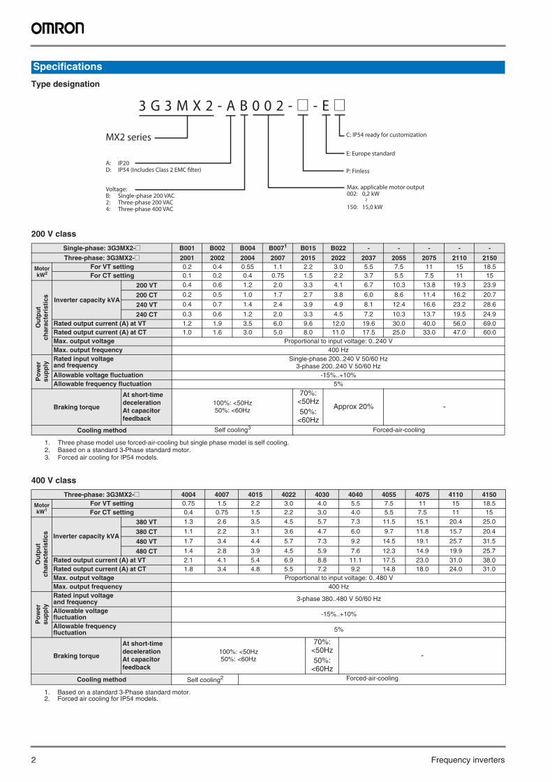
Type designation
200 V class
400 V class
Specifications
Single-phase: 3G3MX2-@ B001 B002 B004 B0071
1. Three phase model use forced-air-cooling but single phase model is self cooling.
B015 B022 - - - - -
Three-phase: 3G3MX2-@ 2001 2002 2004 2007 2015 2022 2037 2055 2075 2110 2150
Motor kW2
2. Based on a standard 3-Phase standard motor.
For VT setting 0.2 0.4 0.55 1.1 2.2 3.0 5.5 7.5 11 15 18.5For CT setting 0.1 0.2 0.4 0.75 1.5 2.2 3.7 5.5 7.5 11 15
Ou
tpu
t ch
arac
teri
stic
s
Inverter capacity kVA
200 VT 0.4 0.6 1.2 2.0 3.3 4.1 6.7 10.3 13.8 19.3 23.9
200 CT 0.2 0.5 1.0 1.7 2.7 3.8 6.0 8.6 11.4 16.2 20.7
240 VT 0.4 0.7 1.4 2.4 3.9 4.9 8.1 12.4 16.6 23.2 28.6
240 CT 0.3 0.6 1.2 2.0 3.3 4.5 7.2 10.3 13.7 19.5 24.9Rated output current (A) at VT 1.2 1.9 3.5 6.0 9.6 12.0 19.6 30.0 40.0 56.0 69.0Rated output current (A) at CT 1.0 1.6 3.0 5.0 8.0 11.0 17.5 25.0 33.0 47.0 60.0Max. output voltage Proportional to input voltage: 0..240 VMax. output frequency 400 Hz
Po
wer
su
pp
ly
Rated input voltageand frequency
Single-phase 200..240 V 50/60 Hz3-phase 200..240 V 50/60 Hz
Allowable voltage fluctuation -15%..+10% Allowable frequency fluctuation 5%
Braking torque
At short-time deceleration At capacitor feedback
100%: <50Hz50%: <60Hz
70%: <50Hz 50%:
<60Hz
Approx 20% -
Cooling method Self cooling3
3. Forced air cooling for IP54 models.
Forced-air-cooling
Three-phase: 3G3MX2-@ 4004 4007 4015 4022 4030 4040 4055 4075 4110 4150
Motor kW1
1. Based on a standard 3-Phase standard motor.
For VT setting 0.75 1.5 2.2 3.0 4.0 5.5 7.5 11 15 18.5For CT setting 0.4 0.75 1.5 2.2 3.0 4.0 5.5 7.5 11 15
Ou
tpu
t ch
arac
teri
stic
s Inverter capacity kVA
380 VT 1.3 2.6 3.5 4.5 5.7 7.3 11.5 15.1 20.4 25.0
380 CT 1.1 2.2 3.1 3.6 4.7 6.0 9.7 11.8 15.7 20.4
480 VT 1.7 3.4 4.4 5.7 7.3 9.2 14.5 19.1 25.7 31.5
480 CT 1.4 2.8 3.9 4.5 5.9 7.6 12.3 14.9 19.9 25.7Rated output current (A) at VT 2.1 4.1 5.4 6.9 8.8 11.1 17.5 23.0 31.0 38.0Rated output current (A) at CT 1.8 3.4 4.8 5.5 7.2 9.2 14.8 18.0 24.0 31.0Max. output voltage Proportional to input voltage: 0..480 VMax. output frequency 400 Hz
Po
wer
su
pp
ly
Rated input voltageand frequency 3-phase 380..480 V 50/60 Hz
Allowable voltage fluctuation -15%..+10%
Allowable frequency fluctuation 5%
Braking torque
At short-time decelerationAt capacitor feedback
100%: <50Hz50%: <60Hz
70%: <50Hz 50%:
<60Hz
-
Cooling method Self cooling2
2. Forced air cooling for IP54 models.
Forced-air-cooling
MX2 series
3 G 3 M X 2 - A B 0 0 2 - @ - E @
A: IP20D: IP54 (Includes Class 2 EMC filter)
Voltage:B: Single-phase 200 VAC2: Three-phase 200 VAC4: Three-phase 400 VAC
Max. applicable motor output002: 0,2 kW ~
150: 15,0 kW
P: Finless
C: IP54 ready for customization
E: Europe standard
MX2 3
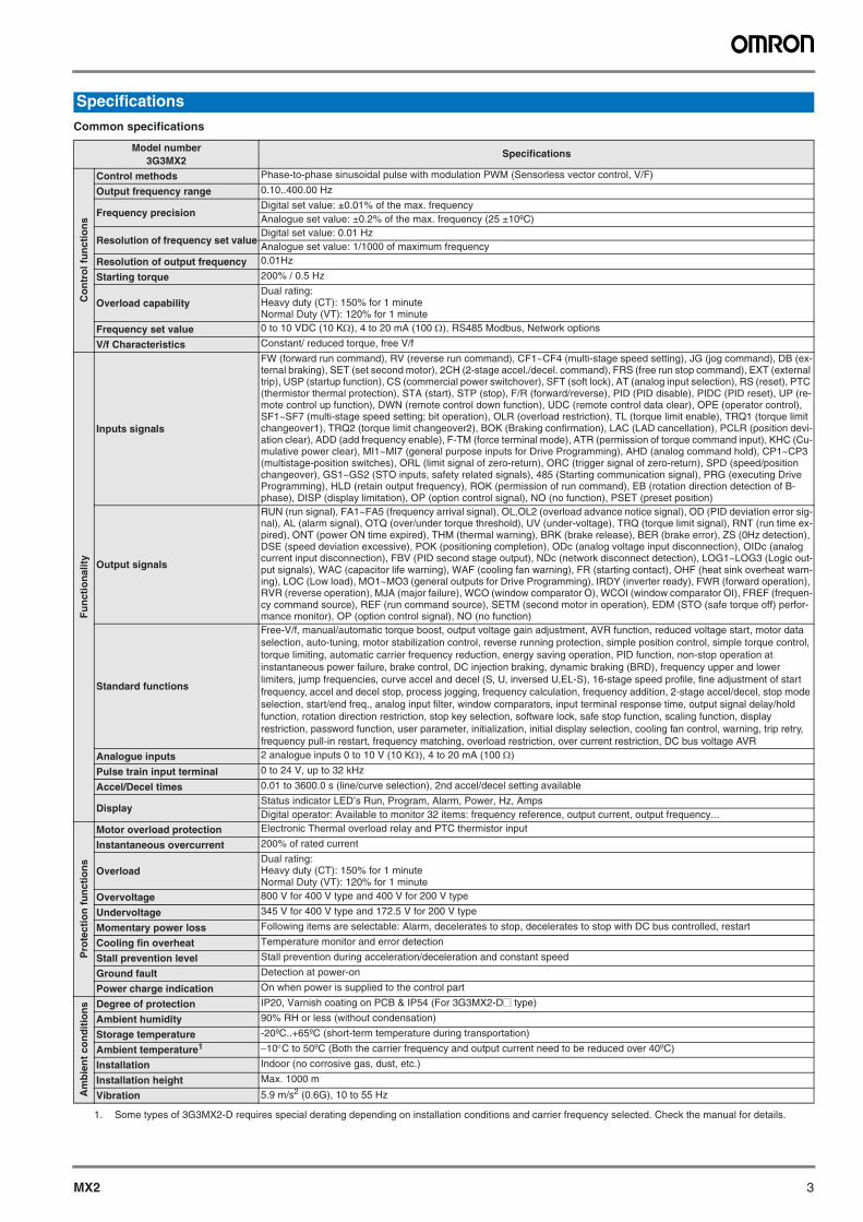
Common specifications
Specifications
Model number3G3MX2
Specifications
Co
ntr
ol f
un
ctio
ns
Control methods Phase-to-phase sinusoidal pulse with modulation PWM (Sensorless vector control, V/F)
Output frequency range 0.10..400.00 Hz
Frequency precisionDigital set value: ±0.01% of the max. frequencyAnalogue set value: ±0.2% of the max. frequency (25 ±10ºC)
Resolution of frequency set valueDigital set value: 0.01 Hz Analogue set value: 1/1000 of maximum frequency
Resolution of output frequency 0.01Hz
Starting torque 200% / 0.5 Hz
Overload capabilityDual rating: Heavy duty (CT): 150% for 1 minuteNormal Duty (VT): 120% for 1 minute
Frequency set value 0 to 10 VDC (10 K), 4 to 20 mA (100 ), RS485 Modbus, Network options
V/f Characteristics Constant/ reduced torque, free V/f
Fu
nct
ion
alit
y
Inputs signals
FW (forward run command), RV (reverse run command), CF1~CF4 (multi-stage speed setting), JG (jog command), DB (ex-ternal braking), SET (set second motor), 2CH (2-stage accel./decel. command), FRS (free run stop command), EXT (external trip), USP (startup function), CS (commercial power switchover), SFT (soft lock), AT (analog input selection), RS (reset), PTC (thermistor thermal protection), STA (start), STP (stop), F/R (forward/reverse), PID (PID disable), PIDC (PID reset), UP (re-mote control up function), DWN (remote control down function), UDC (remote control data clear), OPE (operator control), SF1~SF7 (multi-stage speed setting; bit operation), OLR (overload restriction), TL (torque limit enable), TRQ1 (torque limit changeover1), TRQ2 (torque limit changeover2), BOK (Braking confirmation), LAC (LAD cancellation), PCLR (position devi-ation clear), ADD (add frequency enable), F-TM (force terminal mode), ATR (permission of torque command input), KHC (Cu-mulative power clear), MI1~MI7 (general purpose inputs for Drive Programming), AHD (analog command hold), CP1~CP3 (multistage-position switches), ORL (limit signal of zero-return), ORC (trigger signal of zero-return), SPD (speed/position changeover), GS1~GS2 (STO inputs, safety related signals), 485 (Starting communication signal), PRG (executing Drive Programming), HLD (retain output frequency), ROK (permission of run command), EB (rotation direction detection of B-phase), DISP (display limitation), OP (option control signal), NO (no function), PSET (preset position)
Output signals
RUN (run signal), FA1~FA5 (frequency arrival signal), OL,OL2 (overload advance notice signal), OD (PID deviation error sig-nal), AL (alarm signal), OTQ (over/under torque threshold), UV (under-voltage), TRQ (torque limit signal), RNT (run time ex-pired), ONT (power ON time expired), THM (thermal warning), BRK (brake release), BER (brake error), ZS (0Hz detection), DSE (speed deviation excessive), POK (positioning completion), ODc (analog voltage input disconnection), OIDc (analog current input disconnection), FBV (PID second stage output), NDc (network disconnect detection), LOG1~LOG3 (Logic out-put signals), WAC (capacitor life warning), WAF (cooling fan warning), FR (starting contact), OHF (heat sink overheat warn-ing), LOC (Low load), MO1~MO3 (general outputs for Drive Programming), IRDY (inverter ready), FWR (forward operation), RVR (reverse operation), MJA (major failure), WCO (window comparator O), WCOI (window comparator OI), FREF (frequen-cy command source), REF (run command source), SETM (second motor in operation), EDM (STO (safe torque off) perfor-mance monitor), OP (option control signal), NO (no function)
Standard functions
Free-V/f, manual/automatic torque boost, output voltage gain adjustment, AVR function, reduced voltage start, motor data selection, auto-tuning, motor stabilization control, reverse running protection, simple position control, simple torque control, torque limiting, automatic carrier frequency reduction, energy saving operation, PID function, non-stop operation at instantaneous power failure, brake control, DC injection braking, dynamic braking (BRD), frequency upper and lower limiters, jump frequencies, curve accel and decel (S, U, inversed U,EL-S), 16-stage speed profile, fine adjustment of start frequency, accel and decel stop, process jogging, frequency calculation, frequency addition, 2-stage accel/decel, stop mode selection, start/end freq., analog input filter, window comparators, input terminal response time, output signal delay/hold function, rotation direction restriction, stop key selection, software lock, safe stop function, scaling function, display restriction, password function, user parameter, initialization, initial display selection, cooling fan control, warning, trip retry, frequency pull-in restart, frequency matching, overload restriction, over current restriction, DC bus voltage AVR
Analogue inputs 2 analogue inputs 0 to 10 V (10 K), 4 to 20 mA (100 )
Pulse train input terminal 0 to 24 V, up to 32 kHz
Accel/Decel times 0.01 to 3600.0 s (line/curve selection), 2nd accel/decel setting available
DisplayStatus indicator LED’s Run, Program, Alarm, Power, Hz, AmpsDigital operator: Available to monitor 32 items: frequency reference, output current, output frequency...
Pro
tect
ion
fu
nct
ion
s
Motor overload protection Electronic Thermal overload relay and PTC thermistor input
Instantaneous overcurrent 200% of rated current
OverloadDual rating: Heavy duty (CT): 150% for 1 minuteNormal Duty (VT): 120% for 1 minute
Overvoltage 800 V for 400 V type and 400 V for 200 V type
Undervoltage 345 V for 400 V type and 172.5 V for 200 V type
Momentary power loss Following items are selectable: Alarm, decelerates to stop, decelerates to stop with DC bus controlled, restart
Cooling fin overheat Temperature monitor and error detection
Stall prevention level Stall prevention during acceleration/deceleration and constant speed
Ground fault Detection at power-on
Power charge indication On when power is supplied to the control part
Am
bie
nt
con
dit
ion
s Degree of protection IP20, Varnish coating on PCB & IP54 (For 3G3MX2-D@ type)
Ambient humidity 90% RH or less (without condensation)
Storage temperature -20ºC..+65ºC (short-term temperature during transportation)
Ambient temperature1
1. Some types of 3G3MX2-D requires special derating depending on installation conditions and carrier frequency selected. Check the manual for details.
10C to 50ºC (Both the carrier frequency and output current need to be reduced over 40ºC)
Installation Indoor (no corrosive gas, dust, etc.)
Installation height Max. 1000 m
Vibration 5.9 m/s2 (0.6G), 10 to 55 Hz
4 Frequency inverters
Standard models (IP20)
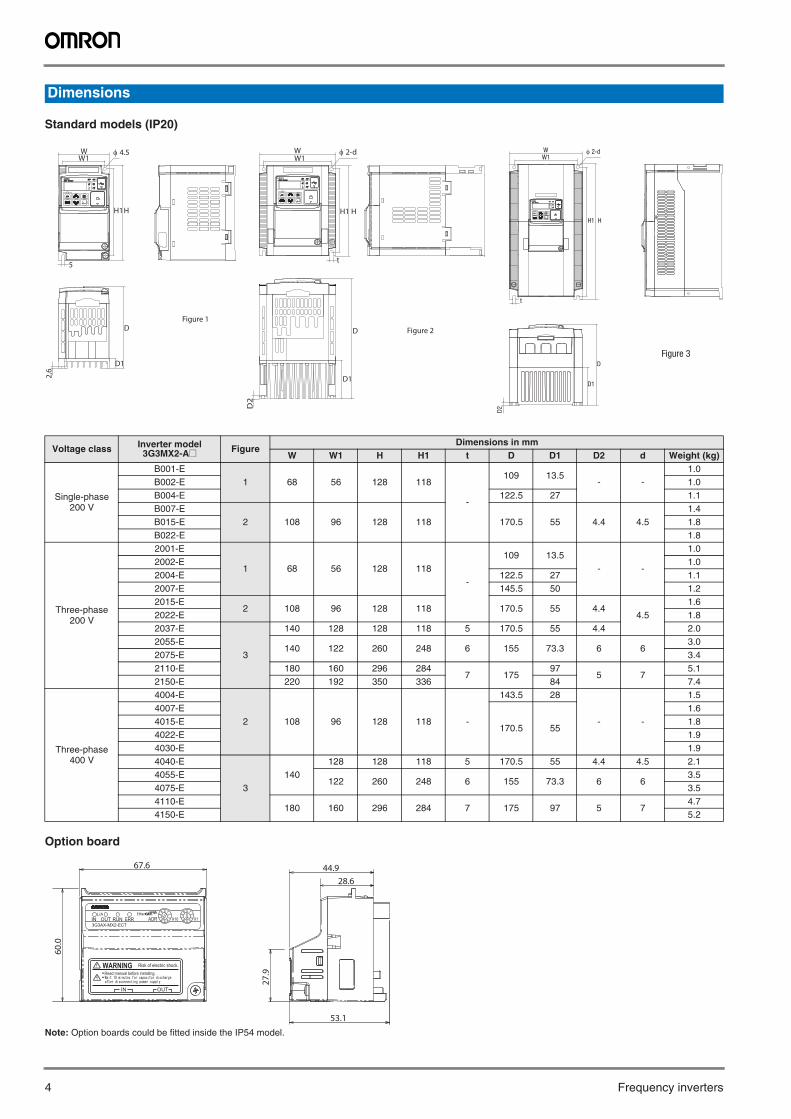
Option board
Note: Option boards could be fitted inside the IP54 model.
Dimensions
Voltage class Inverter model3G3MX2-A@ Figure
Dimensions in mm W W1 H H1 t D D1 D2 d Weight (kg)
Single-phase 200 V
B001-E1 68 56 128 118
-
109 13.5- -
1.0B002-E 1.0B004-E 122.5 27 1.1B007-E
2 108 96 128 118 170.5 55 4.4 4.51.4
B015-E 1.8B022-E 1.8
Three-phase 200 V
2001-E
1 68 56 128 118-
109 13.5- -
1.02002-E 1.02004-E 122.5 27 1.12007-E 145.5 50 1.22015-E
2 108 96 128 118 170.5 55 4.44.5
1.62022-E 1.82037-E
3
140 128 128 118 5 170.5 55 4.4 2.02055-E
140 122 260 248 6 155 73.3 6 63.0
2075-E 3.42110-E 180 160 296 284
7 17597
5 75.1
2150-E 220 192 350 336 84 7.4
Three-phase400 V
4004-E
2 108 96 128 118 -
143.5 28
- -
1.54007-E
170.5 55
1.64015-E 1.84022-E 1.94030-E 1.94040-E
3140
128 128 118 5 170.5 55 4.4 4.5 2.14055-E
122 260 248 6 155 73.3 6 63.5
4075-E 3.54110-E
180 160 296 284 7 175 97 5 74.7
4150-E 5.2
‚o‚v‚q‚o‚v‚q
‚`‚k‚l‚`‚k‚l
‚q‚t‚m‚q‚t‚m
‚g‚š‚g‚š
‚`‚` ‚o‚q‚f‚o‚q‚f
‚q‚t‚m‚q‚t‚m ‚r‚s‚n‚o‚r‚s‚n‚o‚q‚d‚r‚d‚s‚q‚d‚r‚d‚s
‚R‚f‚R‚l‚w‚Q‚R‚f‚R‚l‚w‚Q ?@?@‚h‚m‚u‚d‚q‚s‚d‚q‚h‚m‚u‚d‚q‚s‚d‚q
HH1
W1W 2-d
t
D2
D1
DFigure 3
‚o‚v‚q‚o‚v‚q
‚`‚k‚l‚`‚k‚l
‚q‚t‚m‚q‚t‚m
‚g‚š‚g‚š
‚`‚` ‚o‚q‚f‚o‚q‚f
‚q‚t‚m‚q‚t‚m ‚r‚s‚n‚o‚r‚s‚n‚o‚q‚d‚r‚d‚s‚q‚d‚r‚d‚s
‚R‚f‚R‚l‚w‚Q‚R‚f‚R‚l‚w‚Q ?@?@‚h‚m‚u‚d‚q‚s‚d‚q‚h‚m‚u‚d‚q‚s‚d‚q
HH1
W1W
5
2,6
D1
D
4.5
Figure 1
‚o‚v‚q‚o‚v‚q
‚`‚k‚l‚`‚k‚l
‚q‚t‚m‚q‚t‚m
‚g‚š‚g‚š
‚`‚` ‚o‚q‚f‚o‚q‚f
‚q‚t‚m‚q‚t‚m ‚r‚s‚n‚o‚r‚s‚n‚o‚q‚d‚r‚d‚s‚q‚d‚r‚d‚s
‚R‚f‚R‚l‚w‚Q‚R‚f‚R‚l‚w‚Q ?@?@‚h‚m‚u‚d‚q‚s‚d‚q‚h‚m‚u‚d‚q‚s‚d‚q
H
W1W
t
2-d
D1
D
D2
H1
Figure 2
67.6
27.9
53.1
28.6
60.0
44.9
MX2 5
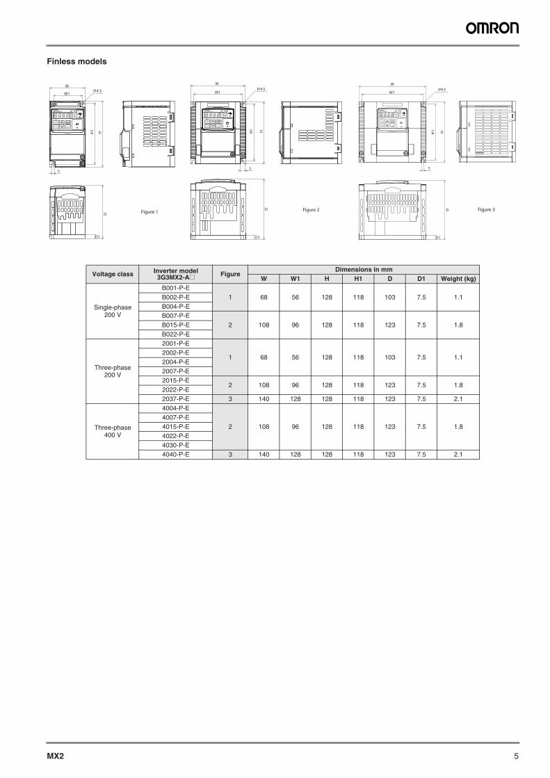
Finless models
Voltage class Inverter model3G3MX2-A@ Figure
Dimensions in mm W W1 H H1 D D1 Weight (kg)
Single-phase200 V
B001-P-E1 68 56 128 118 103 7.5 1.1B002-P-E
B004-P-EB007-P-E
2 108 96 128 118 123 7.5 1.8B015-P-EB022-P-E
Three-phase200 V
2001-P-E
1 68 56 128 118 103 7.5 1.12002-P-E2004-P-E2007-P-E2015-P-E
2 108 96 128 118 123 7.5 1.82022-P-E2037-P-E 3 140 128 128 118 123 7.5 2.1
Three-phase400 V
4004-P-E
2 108 96 128 118 123 7.5 1.84007-P-E4015-P-E4022-P-E4030-P-E4040-P-E 3 140 128 128 118 123 7.5 2.1
8.8.8.8.
WØ4.5
W1
HH1
5
D
D1
Figure 3
8.8.8.8.
W
W1
HH1
5
D
D1
Ø4.5
Figure 2
8.8.8.8.
W
W1Ø4.5
HH1
5
D
D1
Figure 1
6 Frequency inverters
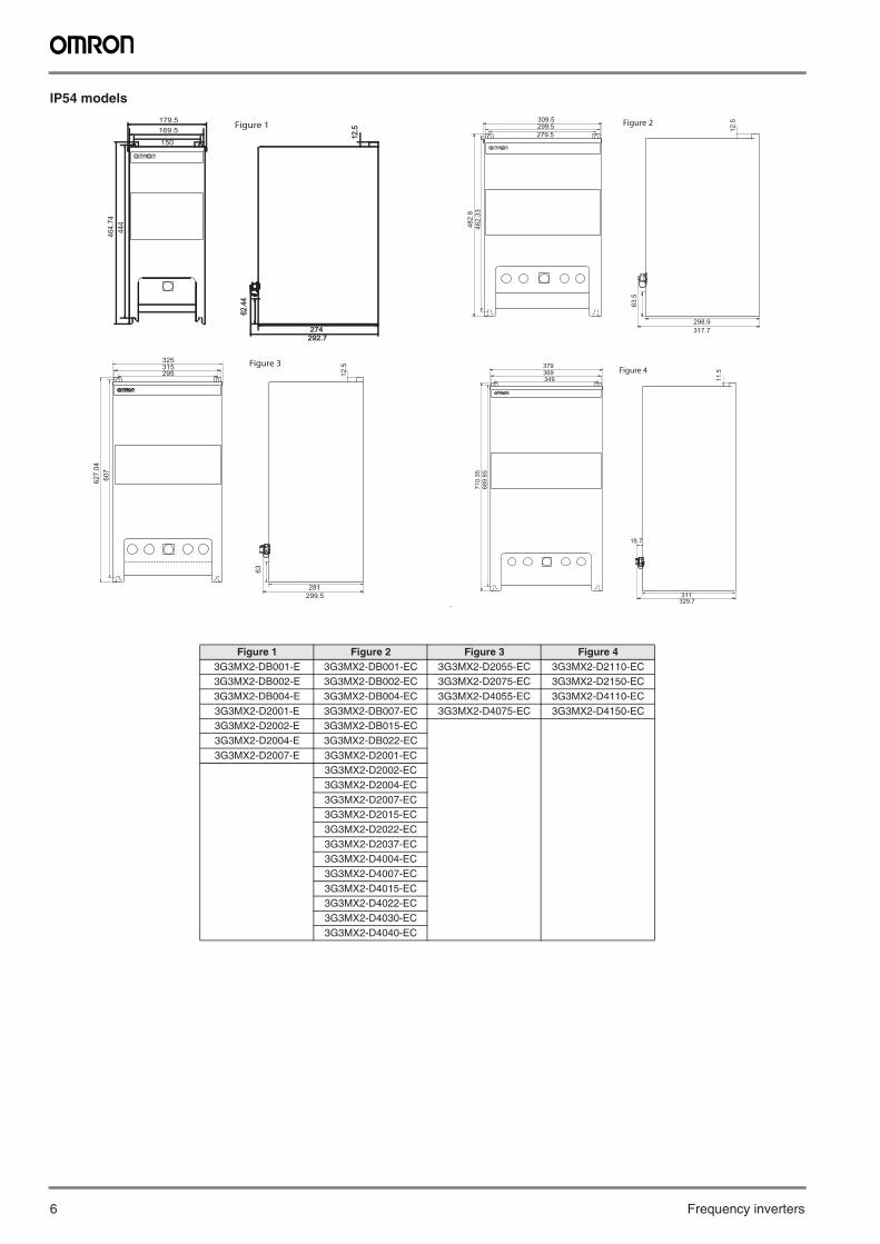
IP54 models
Figure 1 Figure 2 Figure 3 Figure 43G3MX2-DB001-E 3G3MX2-DB001-EC 3G3MX2-D2055-EC 3G3MX2-D2110-EC3G3MX2-DB002-E 3G3MX2-DB002-EC 3G3MX2-D2075-EC 3G3MX2-D2150-EC3G3MX2-DB004-E 3G3MX2-DB004-EC 3G3MX2-D4055-EC 3G3MX2-D4110-EC3G3MX2-D2001-E 3G3MX2-DB007-EC 3G3MX2-D4075-EC 3G3MX2-D4150-EC3G3MX2-D2002-E 3G3MX2-DB015-EC3G3MX2-D2004-E 3G3MX2-DB022-EC3G3MX2-D2007-E 3G3MX2-D2001-EC
3G3MX2-D2002-EC3G3MX2-D2004-EC3G3MX2-D2007-EC3G3MX2-D2015-EC3G3MX2-D2022-EC3G3MX2-D2037-EC3G3MX2-D4004-EC3G3MX2-D4007-EC3G3MX2-D4015-EC3G3MX2-D4022-EC3G3MX2-D4030-EC3G3MX2-D4040-EC
464.
74179.5
274274292.7292.7
150
444
12.5
12.5
62.4
462
.44
169.5Figure 1
309.5
482.
846
2.33
279.5
12.5
298.9317.7
63.5
299.5 Figure 2
299.5281
325
607
627.
04
12.5
295315
63
Figure 3 379
710.
35
311
349369
689.
85
329.7
18.7
Figure 4
11.5
MX2 7
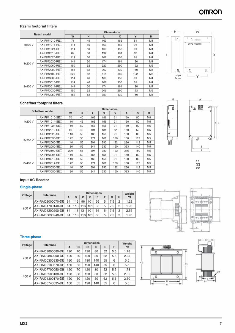
Rasmi footprint filters
Schaffner footprint filters
Input AC Reactor
Single-phase
Three-phase
Rasmi modelDimensions
W H L X Y M
1x200 V
AX-FIM1010-RE@ 71 45 169 156 51 M4
AX-FIM1014-RE@ 111 50 169 156 91 M4
AX-FIM1024-RE@ 111 50 169 156 91 M4
3x200 V
AX-FIM2010-RE@ 82 50 194 181 62 M4
AX-FIM2020-RE@ 111 50 169 156 91 M4
AX-FIM2030-RE@ 144 50 174 161 120 M4
AX-FIM2060-RE@ 150 52 320 290 122 M5
AX-FIM2080-RE@ 188 62 362 330 160 M5
AX-FIM2100-RE@ 220 62 415 380 192 M6
3x400 V
AX-FIM3005-RE@ 114 46 169 156 91 M4
AX-FIM3010-RE@ 114 46 169 156 91 M4
AX-FIM3014-RE@ 144 50 174 161 120 M4
AX-FIM3030-RE@ 150 52 306 290 122 M5
AX-FIM3050-RE@ 182 62 357 330 160 M5
Schaffner modelDimensions
W H L X Y A B M
1x200 V
AX-FIM1010-SE@ 70 40 166 156 51 150 50 M5
AX-FIM1014-SE@ 110 45 166 156 91 150 80 M5
AX-FIM1024-SE@ 110 50 166 156 91 150 80 M5
3x200 V
AX-FIM2010-SE@ 80 40 191 181 62 150 50 M5
AX-FIM2020-SE@ 110 50 166 156 91 150 80 M5
AX-FIM2030-SE@ 142 50 171 161 120 150 112 M5
AX-FIM2060-SE@ 140 55 304 290 122 286 112 M5
AX-FIM2080-SE@ 180 55 344 330 160 323 140 M5
AX-FIM2100-SE@ 220 65 394 380 192 376 180 M5
3x400 V
AX-FIM3005-SE@ 110 50 166 156 91 150 80 M5
AX-FIM3010-SE@ 110 50 166 156 91 150 80 M5
AX-FIM3014-SE@ 142 50 171 161 120 150 112 M5
AX-FIM3030-SE@ 140 55 304 290 122 286 112 M5
AX-FIM3050-SE@ 180 55 344 330 160 323 140 M5
Voltage ReferenceDimensions Weight
kgA B C D E F G H
200 V
AX-RAI02000070-DE 84 113 96 101 66 5 7.5 2 1.22AX-RAI01700140-DE 84 113 116 101 66 5 7.5 2 1.95AX-RAI01200200-DE 84 113 131 101 66 5 7.5 2 2.55AX-RAI00630240-DE 84 113 116 101 66 5 7.5 2 1.95
Voltage ReferenceDimensions Weight
kgA B2 C2 D E F
200 V
AX-RAI02800080-DE 120 70 120 80 52 5.5 1.78AX-RAI00880200-DE 120 80 120 80 62 5.5 2.35AX-RAI00350335-DE 180 85 190 140 55 6 5.5AX-RAI00180670-DE 180 85 190 140 55 6 5.5
400 V
AX-RAI07700050-DE 120 70 120 80 52 5.5 1.78AX-RAI03500100-DE 120 80 120 80 62 5.5 2.35AX-RAI01300170-DE 120 80 120 80 62 5.5 2.50AX-RAI00740335-DE 180 85 190 140 55 6 5.5
L1 N
N'
L1'
AX-FIM1024-SE-V1
LOAD
LINE
XA
YB
L
H W
drive mounts
WH
Y
XL
outputflexes
8 Frequency inverters
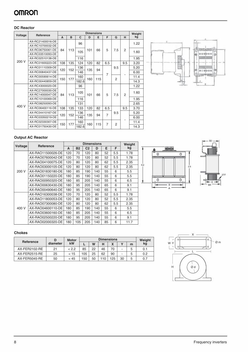
DC Reactor
Output AC Reactor
Chokes
Voltage ReferenceDimensions Weight
kgA B C D E F G H
200 V
AX-RC21400016-DE
84 113
96
101 66 5 7.5 2
1.22AX-RC10700032-DEAX-RC06750061-DE
105 1.60AX-RC03510093-DEAX-RC02510138-DE 116 1.95AX-RC01600223-DE 108 135 124 120 82 6.5
9.59.5 3.20
AX-RC01110309-DE120 152
136135 94
7 -
5.20AX-RC00840437-DE 146 6.00AX-RC00590614-DE
150 177160
160 115 211.4
AX-RC00440859-DE 182.6 14.3
400 V
AX-RC43000020-DE
84 113
96
101 66 5 7.5 2
1.22AX-RC27000030-DE
105 1.60AX-RC14000047-DEAX-RC10100069-DE 116 1.95AX-RC08250093-DE 131 2.65AX-RC06400116-DE 108 135 133 120 82 6.5
9.59.5 3.70
AX-RC04410167-DE120 152
136135 94 7
-
5.20AX-RC03350219-DE 146 6.00AX-RC02330307-DE
150 177160
160 115 7 211.4
AX-RC01750430-DE 182.6 14.3
Voltage ReferenceDimensions Weight
kgA B2 C2 D E F
200 V
AX-RAO11500026-DE 120 70 120 80 52 5.5 1.78AX-RAO07600042-DE 120 70 120 80 52 5.5 1.78AX-RAO04100075-DE 120 80 120 80 62 5.5 2.35AX-RAO03000105-DE 120 80 120 80 62 5.5 2.35AX-RAO01830180-DE 180 85 190 140 55 6 5.5AX-RAO01150220-DE 180 85 190 140 55 6 5.5AX-RAO00950320-DE 180 85 205 140 55 6 6.5AX-RAO00630430-DE 180 95 205 140 65 6 9.1AX-RAO00490640-DE 180 95 205 140 65 6 9.1
400 V
AX-RAO16300038-DE 120 70 120 80 52 5.5 1.78AX-RAO11800053-DE 120 80 120 80 52 5.5 2.35AX-RAO07300080-DE 120 80 120 80 62 5.5 2.35AX-RAO04600110-DE 180 85 190 140 55 6 5.5AX-RAO03600160-DE 180 85 205 140 55 6 6.5AX-RAO02500220-DE 180 95 205 140 55 6 9.1AX-RAO02000320-DE 180 105 205 140 85 6 11.7
Reference D diameter
MotorkW
Dimensions Weight kgL W H X Y m
AX-FER2102-RE 21 < 2.2 85 22 46 70 - 5 0.1AX-FER2515-RE 25 < 15 105 25 62 90 - 5 0.2AX-FER5045-RE 50 < 45 150 50 110 125 30 5 0.7
X
H
YW Ø m
L
Ø d
MX2 9
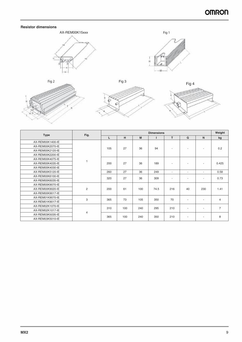
Resistor dimensions
Type Fig.Dimensions Weight
L H M I T G N kg
AX-REM00K1400-IE
1
105 27 36 94 - - - 0.2AX-REM00K2070-IE
AX-REM00K2120-IE
AX-REM00K2200-IE
AX-REM00K4075-IE
200 27 36 189 - - - 0.425AX-REM00K4035-IE
AX-REM00K4030-IE
AX-REM00K5120-IE 260 27 36 249 - - - 0.58
AX-REM00K6100-IE320 27 36 309 - - - 0.73
AX-REM00K6035-IE
AX-REM00K9070-IE
2 200 61 100 74.5 216 40 230 1.41AX-REM00K9020-IE
AX-REM00K9017-IE
AX-REM01K9070-IE3 365 73 105 350 70 - - 4
AX-REM01K9017-IE
AX-REM02K1070-IE
4
310 100 240 295 210 - - 7AX-REM02K1017-IE
AX-REM03K5035-IE365 100 240 350 210 - - 8
AX-REM03K5010-IE
168
13
45
20
182
AX-REM00K15xxx Fig 1
Fig 3Fig 4
Fig 2
10 Frequency inverters
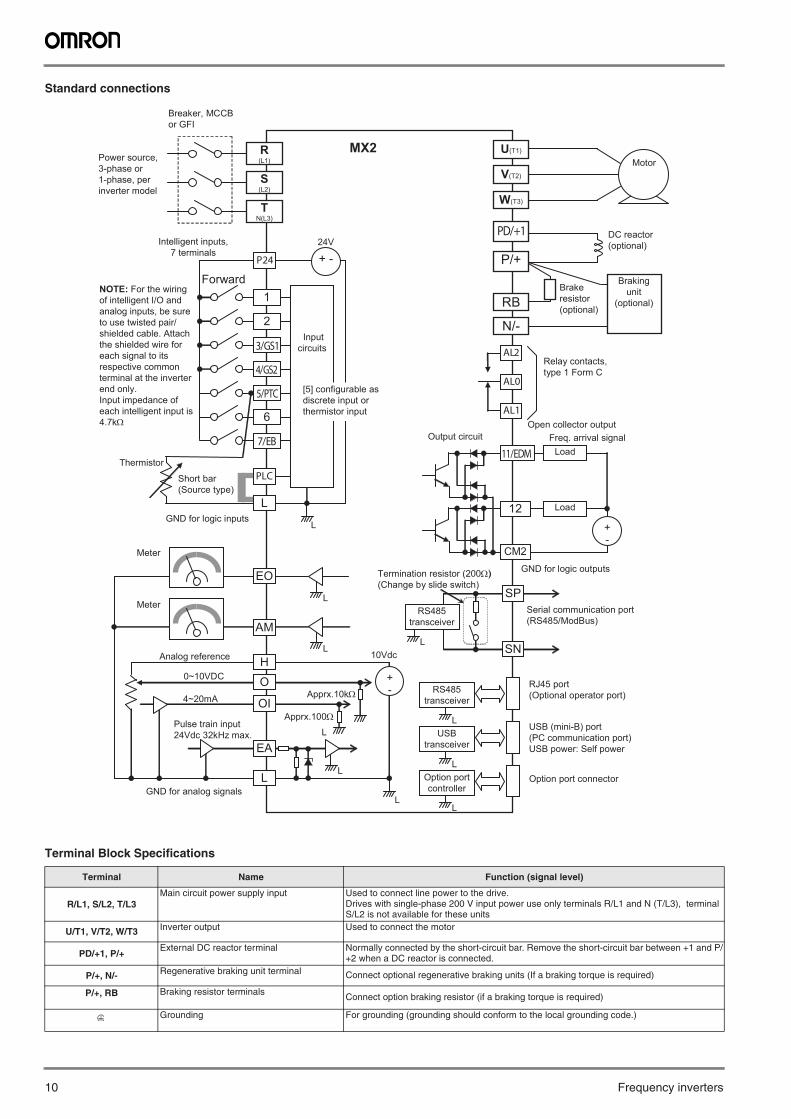
Standard connections
Terminal Block Specifications
Terminal Name Function (signal level)
R/L1, S/L2, T/L3Main circuit power supply input Used to connect line power to the drive.
Drives with single-phase 200 V input power use only terminals R/L1 and N (T/L3), terminal S/L2 is not available for these units
U/T1, V/T2, W/T3 Inverter output Used to connect the motor
PD/+1, P/+External DC reactor terminal Normally connected by the short-circuit bar. Remove the short-circuit bar between +1 and P/
+2 when a DC reactor is connected.
P/+, N/- Regenerative braking unit terminal Connect optional regenerative braking units (If a braking torque is required)
P/+, RB Braking resistor terminals Connect option braking resistor (if a braking torque is required)
Grounding For grounding (grounding should conform to the local grounding code.)
Inputcircuits
24V
P24 + -
1
2
3/GS1
4/GS2
5/PTC
Forward
Thermistor
GND for logic inputs
AM
Meter
H
L
Analog reference
0~10VDC
4~20mA
GND for analog signals
MX2 Motor
PD/+1
P/+
R (L1)
S (L2)
T N(L3)
U(T1)
V(T2)
W(T3)
N/-
AL2
AL0
AL1
6
7/EB
EO
Meter
RB
11/EDM Load Freq. arrival signal
Open collector output Output circuit
GND for logic outputs
12 Load
+ -
CM2
L
L
+ -
O
OI
EA
Apprx.10k
10Vdc
Apprx.100
L
L
Option port connector
L
L
L
L
L
L
SP
SN
)
L
PLC Short bar(Source type)
Breaker, MCCB or GFI
Power source, 3-phase or 1-phase, per inverter model
Intelligent inputs, 7 terminals
NOTE: For the wiring of intelligent I/O and analog inputs, be sure to use twisted pair/shielded cable. Attach the shielded wire for each signal to its respective common terminal at the inverter end only.Input impedance of each intelligent input is 4.7k
[5] configurable as discrete input or thermistor input
Pulse train input 24Vdc 32kHz max.
RS485 transceiver
USB transceiver
Option port controller
USB (mini-B) port (PC communication port) USB power: Self power
RJ45 port(Optional operator port)
RS485 transceiver
Serial communication port (RS485/ModBus)
Termination resistor (200(Change by slide switch)
Relay contacts, type 1 Form C
Brake resistor (optional)
Brakingunit
(optional)
DC reactor (optional)
MX2 11
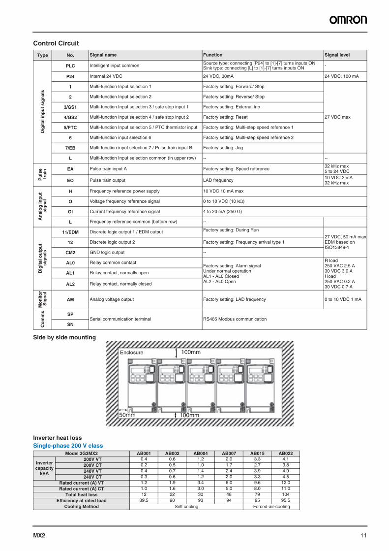
Control Circuit
Side by side mounting
Inverter heat lossSingle-phase 200 V class
Type No. Signal name Function Signal level
Dig
ital
inp
ut
sig
nal
s
PLC Intelligent input common Source type: connecting [P24] to [1]-[7] turns inputs ONSink type: connecting [L] to [1]-[7] turns inputs ON -
P24 Internal 24 VDC 24 VDC, 30mA 24 VDC, 100 mA
1 Multi-function Input selection 1 Factory setting: Forward/ Stop
27 VDC max
2 Multi-function Input selection 2 Factory setting: Reverse/ Stop
3/GS1 Multi-function Input selection 3 / safe stop input 1 Factory setting: External trip
4/GS2 Multi-function Input selection 4 / safe stop input 2 Factory setting: Reset
5/PTC Multi-function Input selection 5 / PTC thermistor input Factory setting: Multi-step speed reference 1
6 Multi-function input selection 6 Factory setting: Multi-step speed reference 2
7/EB Multi-function input selection 7 / Pulse train input B Factory setting: Jog
L Multi-function Input selection common (in upper row) -- --
Pu
lse
tra
in EA Pulse train input A Factory setting: Speed reference 32 kHz max 5 to 24 VDC
EO Pulse train output LAD frequency 10 VDC 2 mA32 kHz max
An
alo
g in
pu
t s
ign
al
H Frequency reference power supply 10 VDC 10 mA max
O Voltage frequency reference signal 0 to 10 VDC (10 k)
OI Current frequency reference signal 4 to 20 mA (250 )
L Frequency reference common (bottom row) --
Dig
ital
ou
tpu
t s
ign
als
11/EDM Discrete logic output 1 / EDM output Factory setting: During Run
27 VDC, 50 mA maxEDM based on ISO13849-1
12 Discrete logic output 2 Factory setting: Frequency arrival type 1
CM2 GND logic output --
AL0 Relay common contactFactory setting: Alarm signalUnder normal operation AL1 - AL0 ClosedAL2 - AL0 Open
R load250 VAC 2.5 A30 VDC 3.0 AI load250 VAC 0.2 A30 VDC 0.7 A
AL1 Relay contact, normally open
AL2 Relay contact, normally closed
Mo
nit
or
Sig
nal
AM Analog voltage output Factory setting: LAD frequency 0 to 10 VDC 1 mA
Co
mm
s SPSerial communication terminal RS485 Modbus communication
SN
Model 3G3MX2 AB001 AB002 AB004 AB007 AB015 AB022
Inverter capacity
kVA
200V VT 0.4 0.6 1.2 2.0 3.3 4.1200V CT 0.2 0.5 1.0 1.7 2.7 3.8240V VT 0.4 0.7 1.4 2.4 3.9 4.9240V CT 0.3 0.6 1.2 2.0 3.3 4.5
Rated current (A) VT 1.2 1.9 3.4 6.0 9.6 12.0Rated current (A) CT 1.0 1.6 3.0 5.0 8.0 11.0
Total heat loss 12 22 30 48 79 104Efficiency at rated load 89.5 90 93 94 95 95.5
Cooling Method Self cooling Forced-air-cooling
Enclosure 100mm
100mm50mm
12 Frequency inverters
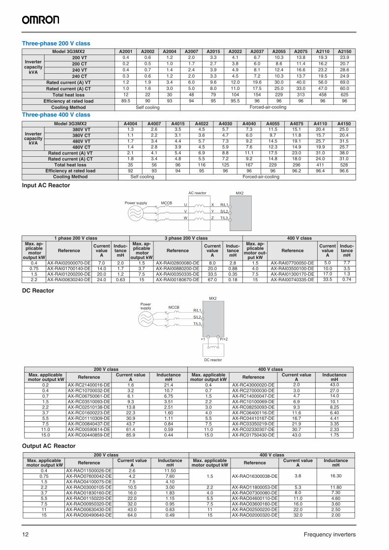
Three-phase 200 V class
Three-phase 400 V class
Input AC Reactor
DC Reactor
Output AC Reactor
Model 3G3MX2 A2001 A2002 A2004 A2007 A2015 A2022 A2037 A2055 A2075 A2110 A2150
Inverter capacity
kVA
200 VT 0.4 0.6 1.2 2.0 3.3 4.1 6.7 10.3 13.8 19.3 23.9200 CT 0.2 0.5 1.0 1.7 2.7 3.8 6.0 8.6 11.4 16.2 20.7240 VT 0.4 0.7 1.4 2.4 3.9 4.9 8.1 12.4 16.6 23.2 28.6240 CT 0.3 0.6 1.2 2.0 3.3 4.5 7.2 10.3 13.7 19.5 24.9
Rated current (A) VT 1.2 1.9 3.4 6.0 9.6 12.0 19.6 30.0 40.0 56.0 69.0Rated current (A) CT 1.0 1.6 3.0 5.0 8.0 11.0 17.5 25.0 33.0 47.0 60.0
Total heat loss 12 22 30 48 79 104 154 229 313 458 625Efficiency at rated load 89.5 90 93 94 95 95.5 96 96 96 96 96
Cooling Method Self cooling Forced-air-cooling
Model 3G3MX2 A4004 A4007 A4015 A4022 A4030 A4040 A4055 A4075 A4110 A4150
Inverter capacity
kVA
380V VT 1.3 2.6 3.5 4.5 5.7 7.3 11.5 15.1 20.4 25.0380V CT 1.1 2.2 3.1 3.6 4.7 6.0 9.7 11.8 15.7 20.4480V VT 1.7 3.4 4.4 5.7 7.3 9.2 14.5 19.1 25.7 31.5480V CT 1.4 2.8 3.9 4.5 5.9 7.6 12.3 14.9 19.9 25.7
Rated current (A) VT 2.1 4.1 5.4 6.9 8.8 11.1 17.5 23.0 31.0 38.0Rated current (A) CT 1.8 3.4 4.8 5.5 7.2 9.2 14.8 18.0 24.0 31.0
Total heat loss 35 56 96 116 125 167 229 296 411 528Efficiency at rated load 92 93 94 95 96 96 96 96.2 96.4 96.6
Cooling Method Self cooling Forced-air-cooling
1 phase 200 V class 3 phase 200 V class 400 V classMax. ap-plicable motor
output kW
ReferenceCurrent value
A
Induc-tancemH
Max. ap-plicable motor
output kW
ReferenceCurrent value
A
Induc-tancemH
Max. ap-plicable
motor out-put kW
ReferenceCurrent value
A
Induc-tancemH
0.4 AX-RAI02000070-DE 7.0 2.0 1.5 AX-RAI02800080-DE 8.0 2.8 1.5 AX-RAI07700050-DE 5.0 7.70.75 AX-RAI01700140-DE 14.0 1.7 3.7 AX-RAI00880200-DE 20.0 0.88 4.0 AX-RAI03500100-DE 10.0 3.51.5 AX-RAI01200200-DE 20.0 1.2 7.5 AX-RAI00350335-DE 33.5 0.35 7.5 AX-RAI01300170-DE 17.0 1.32.2 AX-RAI00630240-DE 24.0 0.63 15 AX-RAI00180670-DE 67.0 0.18 15 AX-RAI00740335-DE 33.5 0.74
200 V class 400 V classMax. applicable
motor output kW Reference Current value A
InductancemH
Max. applicable motor output kW Reference Current value
AInductance
mH0.2 AX-RC21400016-DE 1.6 21.4 0.4 AX-RC43000020-DE 2.0 43.00.4 AX-RC10700032-DE 3.2 10.7 0.7 AX-RC27000030-DE 3.0 27.00.7 AX-RC06750061-DE 6.1 6.75 1.5 AX-RC14000047-DE 4.7 14.01.5 AX-RC03510093-DE 9.3 3.51 2.2 AX-RC10100069-DE 6.9 10.12.2 AX-RC02510138-DE 13.8 2.51 3.0 AX-RC08250093-DE 9.3 8.253.7 AX-RC01600223-DE 22.3 1.60 4.0 AX-RC06400116-DE 11.6 6.405.5 AX-RC01110309-DE 30.9 1.11 5.5 AX-RC04410167-DE 16.7 4.417.5 AX-RC00840437-DE 43.7 0.84 7.5 AX-RC03350219-DE 21.9 3.3511.0 AX-RC00590614-DE 61.4 0.59 11.0 AX-RC02330307-DE 30.7 2.3315.0 AX-RC00440859-DE 85.9 0.44 15.0 AX-RC01750430-DE 43.0 1.75
200 V class 400 V classMax. applicable
motor output kW Reference Current value A
InductancemH
Max. applicable motor output kW Reference Current value
AInductance
mH0.4 AX-RAO11500026-DE 2.6 11.50
1.5 AX-RAO16300038-DE 3.8 16.300.75 AX-RAO07600042-DE 4.2 7.601.5 AX-RAO04100075-DE 7.5 4.102.2 AX-RAO03000105-DE 10.5 3.00 2.2 AX-RAO11800053-DE 5.3 11.803.7 AX-RAO01830160-DE 16.0 1.83 4.0 AX-RAO07300080-DE 8.0 7.305.5 AX-RAO01150220-DE 22.0 1.15 5.5 AX-RAO04600110-DE 11.0 4.607.5 AX-RAO00950320-DE 32.0 0.95 7.5 AX-RAO03600160-DE 16.0 3.6011 AX-RAO00630430-DE 43.0 0.63 11 AX-RAO02500220-DE 22.0 2.5015 AX-RAO00490640-DE 64.0 0.49 15 AX-RAO02000320-DE 32.0 2.00
MCCBPower supply
AC reactor MX2
R/L1U
V
W
X
Y
Z
S/L2
T/L3
Powersupply
MX2
DC reactor
R/L1
+1 P/+2
MCCB
S/L2
T/L3
MX2 13
3G3MX2
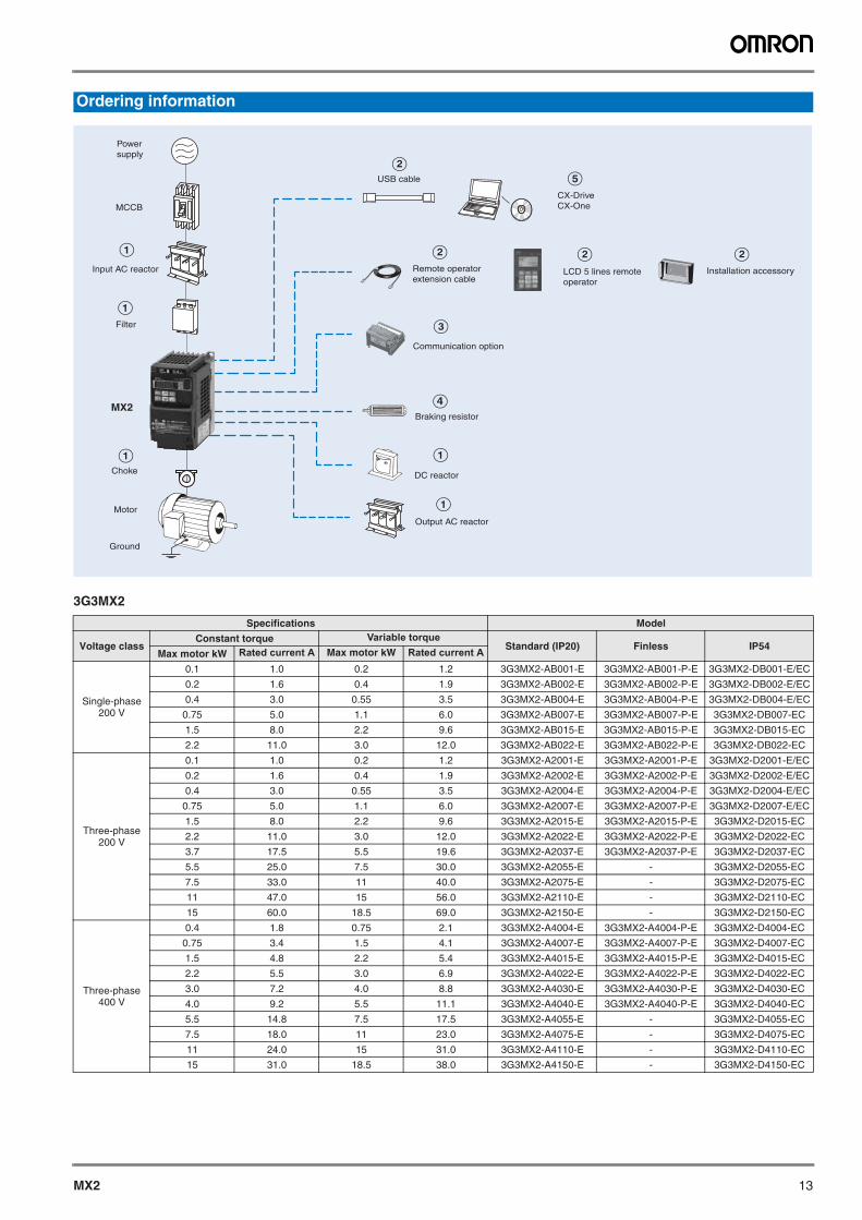
Ordering information
Specifications Model
Voltage classConstant torque Variable torque
Standard (IP20) Finless IP54Max motor kW Rated current A Max motor kW Rated current A
Single-phase200 V
0.1 1.0 0.2 1.2 3G3MX2-AB001-E 3G3MX2-AB001-P-E 3G3MX2-DB001-E/EC
0.2 1.6 0.4 1.9 3G3MX2-AB002-E 3G3MX2-AB002-P-E 3G3MX2-DB002-E/EC
0.4 3.0 0.55 3.5 3G3MX2-AB004-E 3G3MX2-AB004-P-E 3G3MX2-DB004-E/EC
0.75 5.0 1.1 6.0 3G3MX2-AB007-E 3G3MX2-AB007-P-E 3G3MX2-DB007-EC
1.5 8.0 2.2 9.6 3G3MX2-AB015-E 3G3MX2-AB015-P-E 3G3MX2-DB015-EC
2.2 11.0 3.0 12.0 3G3MX2-AB022-E 3G3MX2-AB022-P-E 3G3MX2-DB022-EC
Three-phase200 V
0.1 1.0 0.2 1.2 3G3MX2-A2001-E 3G3MX2-A2001-P-E 3G3MX2-D2001-E/EC
0.2 1.6 0.4 1.9 3G3MX2-A2002-E 3G3MX2-A2002-P-E 3G3MX2-D2002-E/EC
0.4 3.0 0.55 3.5 3G3MX2-A2004-E 3G3MX2-A2004-P-E 3G3MX2-D2004-E/EC
0.75 5.0 1.1 6.0 3G3MX2-A2007-E 3G3MX2-A2007-P-E 3G3MX2-D2007-E/EC
1.5 8.0 2.2 9.6 3G3MX2-A2015-E 3G3MX2-A2015-P-E 3G3MX2-D2015-EC
2.2 11.0 3.0 12.0 3G3MX2-A2022-E 3G3MX2-A2022-P-E 3G3MX2-D2022-EC
3.7 17.5 5.5 19.6 3G3MX2-A2037-E 3G3MX2-A2037-P-E 3G3MX2-D2037-EC
5.5 25.0 7.5 30.0 3G3MX2-A2055-E - 3G3MX2-D2055-EC
7.5 33.0 11 40.0 3G3MX2-A2075-E - 3G3MX2-D2075-EC
11 47.0 15 56.0 3G3MX2-A2110-E - 3G3MX2-D2110-EC
15 60.0 18.5 69.0 3G3MX2-A2150-E - 3G3MX2-D2150-EC
Three-phase400 V
0.4 1.8 0.75 2.1 3G3MX2-A4004-E 3G3MX2-A4004-P-E 3G3MX2-D4004-EC
0.75 3.4 1.5 4.1 3G3MX2-A4007-E 3G3MX2-A4007-P-E 3G3MX2-D4007-EC
1.5 4.8 2.2 5.4 3G3MX2-A4015-E 3G3MX2-A4015-P-E 3G3MX2-D4015-EC
2.2 5.5 3.0 6.9 3G3MX2-A4022-E 3G3MX2-A4022-P-E 3G3MX2-D4022-EC
3.0 7.2 4.0 8.8 3G3MX2-A4030-E 3G3MX2-A4030-P-E 3G3MX2-D4030-EC
4.0 9.2 5.5 11.1 3G3MX2-A4040-E 3G3MX2-A4040-P-E 3G3MX2-D4040-EC
5.5 14.8 7.5 17.5 3G3MX2-A4055-E - 3G3MX2-D4055-EC
7.5 18.0 11 23.0 3G3MX2-A4075-E - 3G3MX2-D4075-EC
11 24.0 15 31.0 3G3MX2-A4110-E - 3G3MX2-D4110-EC
15 31.0 18.5 38.0 3G3MX2-A4150-E - 3G3MX2-D4150-EC
A
B B
A
A
C
A
D
B
BE
A
Choke
LCD 5 lines remote operator
Remote operator extension cable
Output AC reactor
Communication option
USB cable
Braking resistor
CX-Drive CX-One
Installation accessory
MCCB
MX2
Filter
Input AC reactor
Motor
Ground
Power supply
DC reactor
14 Frequency inverters
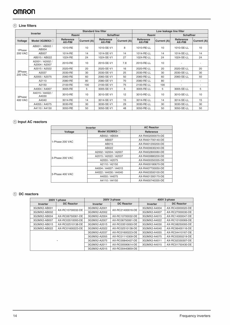
A Line filters
A Input AC reactors
A DC reactors
InverterStandard line filter Low leakage line filter
Rasmi Schaffner Rasmi Schaffner
Voltage Model 3G3MX2-@ Reference AX-FIM Current (A) Reference
AX-FIM Current (A) Reference AX-FIM Current (A) Reference
AX-FIM Current (A)
1Phase 200 VAC
AB001 / AB002 / AB004 1010-RE 10 1010-SE-V1 8 1010-RE-LL 10 1010-SE-LL 10
AB007 1014-RE 14 1014-SE-V1 14 1014-RE-LL 14 1014-SE-LL 14
AB015 / AB022 1024-RE 24 1024-SE-V1 27 1024-RE-LL 24 1024-SE-LL 24
3Phase 200 VAC
A2001 / A2002 / A2004 / A2007 2010-RE 10 2010-SE-V1 7.8 2010-RE-LL 10 - -
A2015 / A2022 2020-RE 20 2020-SE-V1 16 2020-RE-LL 20 2020-SE-LL 20
A2037 2030-RE 30 2030-SE-V1 25 2030-RE-LL 30 2030-SE-LL 30
A2055 / A2075 2060-RE 60 2060-SE-V1 50 2060-RE-LL 60 2060-SE-LL 50
A2110 2080-RE 80 2080-SE-V1 70 2080-RE-LL 80 - -
A2150 2100-RE 100 2100-SE-V1 75 2100-RE-LL 100 - -
3Phase 400 VAC
A4004 / A4007 3005-RE 5 3005-SE-V1 6 3005-RE-LL 5 3005-SE-LL 5
A4015 / A4022 / A4030 3010-RE 10 3010-SE-V1 12 3010-RE-LL 10 3010-SE-LL 10
A4040 3014-RE 14 3014-SE-V1 15 3014-RE-LL 14 3014-SE-LL 15
A4055 / A4075 3030-RE 30 3030-SE-V1 29 3030-RE-LL 30 3030-SE-LL 30
A4110 / A4150 3050-RE 50 3050-SE-V1 48 3050-RE-LL 50 3050-SE-LL 50
Inverter AC Reactor
Voltage Model 3G3MX2-@ Reference
1-Phase 200 VAC
AB002 / AB004 AX-RAI02000070-DE
AB007 AX-RAI01700140-DE
AB015 AX-RAI01200200-DE
AB022 AX-RAI00630240-DE
3-Phase 200 VAC
A2002 / A2004 / A2007 AX-RAI02800080-DE
A2015 / A2022 / A2037 AX-RAI00880200-DE
A2055 / A2075 AX-RAI00350335-DE
A2110 / A2150 AX-RAI00180670-DE
3-Phase 400 VAC
A4004 / A4007 / A4015 AX-RAI07700050-DE
A4022 / A4030 / A4040 AX-RAI03500100-DE
A4055 / A4075 AX-RAI01300170-DE
A4110 / A4150 AX-RAI00740335-DE
200V 1-phase 200V 3-phase 400V 3-phase
Inverter DC Reactor Inverter DC Reactor Inverter DC Reactor
3G3MX2-AB001AX-RC10700032-DE
3G3MX2-A2001AX-RC21400016-DE
3G3MX2-A4004 AX-RC43000020-DE
3G3MX2-AB002 3G3MX2-A2002 3G3MX2-A4007 AX-RC27000030-DE
3G3MX2-AB004 AX-RC06750061-DE 3G3MX2-A2004 AX-RC10700032-DE 3G3MX2-A4015 AX-RC14000047-DE
3G3MX2-AB007 AX-RC03510093-DE 3G3MX2-A2007 AX-RC06750061-DE 3G3MX2-A4022 AX-RC10100069-DE
3G3MX2-AB015 AX-RC02510138-DE 3G3MX2-A2015 AX-RC03510093-DE 3G3MX2-A4030 AX-RC08250093-DE
3G3MX2-AB022 AX-RC01600223-DE 3G3MX2-A2022 AX-RC02510138-DE 3G3MX2-A4040 AX-RC06400116-DE
-
3G3MX2-A2037 AX-RC01600223-DE 3G3MX2-A4055 AX-RC04410167-DE
3G3MX2-A2055 AX-RC01110309-DE 3G3MX2-A4075 AX-RC03350219-DE
3G3MX2-A2075 AX-RC00840437-DE 3G3MX2-A4011 AX-RC02330307-DE
3G3MX2-A2011 AX-RC00590614-DE 3G3MX2-A4015 AX-RC01750430-DE
3G3MX2-A2015 AX-RC00440859-DE -
MX2 15
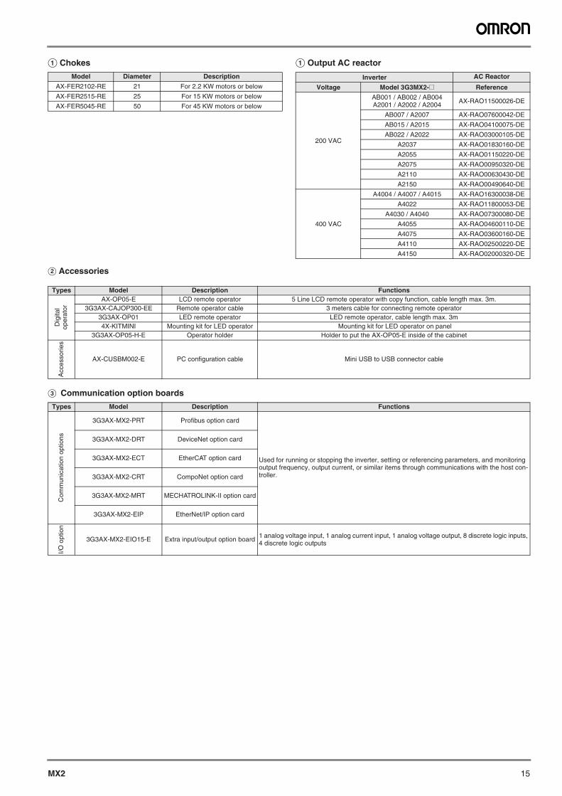
A Chokes A Output AC reactor
B Accessories
C Communication option boards
Model Diameter Description
AX-FER2102-RE 21 For 2.2 KW motors or below
AX-FER2515-RE 25 For 15 KW motors or below
AX-FER5045-RE 50 For 45 KW motors or below
Inverter AC Reactor
Voltage Model 3G3MX2-@ Reference
200 VAC
AB001 / AB002 / AB004A2001 / A2002 / A2004 AX-RAO11500026-DE
AB007 / A2007 AX-RAO07600042-DE
AB015 / A2015 AX-RAO04100075-DE
AB022 / A2022 AX-RAO03000105-DE
A2037 AX-RAO01830160-DE
A2055 AX-RAO01150220-DE
A2075 AX-RAO00950320-DE
A2110 AX-RAO00630430-DE
A2150 AX-RAO00490640-DE
400 VAC
A4004 / A4007 / A4015 AX-RAO16300038-DE
A4022 AX-RAO11800053-DE
A4030 / A4040 AX-RAO07300080-DE
A4055 AX-RAO04600110-DE
A4075 AX-RAO03600160-DE
A4110 AX-RAO02500220-DE
A4150 AX-RAO02000320-DE
Types Model Description Functions
Dig
ital
oper
ator
AX-OP05-E LCD remote operator 5 Line LCD remote operator with copy function, cable length max. 3m.3G3AX-CAJOP300-EE Remote operator cable 3 meters cable for connecting remote operator
3G3AX-OP01 LED remote operator LED remote operator, cable length max. 3m4X-KITMINI Mounting kit for LED operator Mounting kit for LED operator on panel
3G3AX-OP05-H-E Operator holder Holder to put the AX-OP05-E inside of the cabinet
Acc
esso
ries
AX-CUSBM002-E PC configuration cable Mini USB to USB connector cable
Types Model Description Functions
Com
mun
icat
ion
optio
ns
3G3AX-MX2-PRT Profibus option card
Used for running or stopping the inverter, setting or referencing parameters, and monitoring output frequency, output current, or similar items through communications with the host con-troller.
3G3AX-MX2-DRT DeviceNet option card
3G3AX-MX2-ECT EtherCAT option card
3G3AX-MX2-CRT CompoNet option card
3G3AX-MX2-MRT MECHATROLINK-II option card
3G3AX-MX2-EIP EtherNet/IP option card
I/O o
ptio
n
3G3AX-MX2-EIO15-E Extra input/output option board 1 analog voltage input, 1 analog current input, 1 analog voltage output, 8 discrete logic inputs, 4 discrete logic outputs
16 Frequency inverters
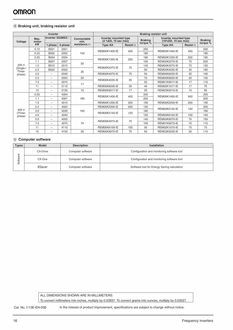
D Braking unit, braking resistor unit
E Computer software
Inverter Braking resistor unit
VoltageMax.
motorkW
Inverter 3G3MX2@ Connectable min.
resistance
Inverter mounted type (3 %ED, 10 sec max) Braking
torque %
Inverter mounted type (10%ED, 10 sec max) Braking
torque %1-phase 3-phase Type AX- Resist Type AX- Resist
200 V (Single-/Three-phase)
0.12 B001 2001
100REM00K1400-IE 400
200REM00K1400-IE 400
200
0.25 B002 2002 180 180
0.55 B004 2004REM00K1200-IE 200
180 REM00K1200-IE 200 180
1.1 B007 200750
100 REM00K2070-IE 70 200
1.5 B015 2015REM00K2070-IE 70
140 REM00K4075-IE 75 130
2.2 B022 202235
90 REM00K4035-IE 35 180
4.0 – 2040 REM00K4075-IE 75 50 REM00K6035-IE 35 100
5.5 – 2055 20REM00K4035-IE 35
75 REM00K9020-IE 20 150
7.5 – 207517
55 REM01K9017-IE 17 110
11 – 2110 REM00K6035-IE 35 40 REM02K1017-IE 17 75
15 – 2150 10 REM00K9017-IE 17 55 REM03K5010-IE 10 95
400 V(Three-phase)
0.55 – 4004
180REM00K1400-IE 400
200REM00K1400-IE 400
200
1.1 – 4007 200 200
1.5 – 4015 REM00K1200-IE 200 190 REM00K2200-IE 200 190
2.2 – 4022
100
REM00K2200-IE 200 130REM00K5120-IE 120
200
3.0 – 4030REM00K2120-IE 120
160 160
4.0 – 4040 120 REM00K6100-IE 100 140
5.5 – 4055
70REM00K4075-IE 75
140 REM00K9070-IE 70 150
7.5 – 4075 100 REM01K9070-IE 70 110
11 – 4110 REM00K6100-IE 100 50 REM02K1070-IE 70 75
15 – 4150 35 REM00K9070-IE 70 55 REM03K5035-IE 35 110
Types Model Description Installation
Sof
twar
e
CX-Drive Computer software Configuration and monitoring software tool
CX-One Computer software Configuration and monitoring software tool
€Saver Computer software Software tool for Energy Saving calculation
In the interest of product improvement, specifications are subject to change without notice.
ALL DIMENSIONS SHOWN ARE IN MILLIMETERS.
To convert millimeters into inches, multiply by 0.03937. To convert grams into ounces, multiply by 0.03527.
Cat. No. I113E-EN-05B