Embed Size (px)
Citation preview
MX7000 Series Metallurgical Microscope Instruction Manual
Table of Contents 1.0 Introduction 1.1 Microscope Features 1.2 General Safety Guidelines 1.3 Intended Product Use Statement 1.4 Handling the microscope 1.5 Warranty Notes 2.0 The Microscope and its Components 2.1 Installation Site 2.2 Unpacking 2.3 Microscope Set Up 2.4 Adjusting Interpupillary Distance 3.0 Microscope Operation 3.1 Centering the Lamp – Incident Illuminator 3.2 Incident Light Operation – Brightfield 3.3 Using the Polarizer / Slide-In Analyzer 3.4 Photomicrography with 35mm SLR and Digital SLR Cameras 3.5 Photomicrography with Digital Still Cameras 3.6 Connecting a Video or Other Camera that uses a “C” type mount 4.0 Maintenance and Cleaning 5.0 Troubleshooting 5.1 Replacing the mains fuse on the microscope 5.2 Incident Light does not work 5.3 Replacing the 6V 30W Halogen Lamp – Incident Illuminator 6.0 Storage 7.0 Packing and Transport 8.0 Accessories and Replacements Parts 9.0 Technical Descriptions 10.0 Physical Dimensions
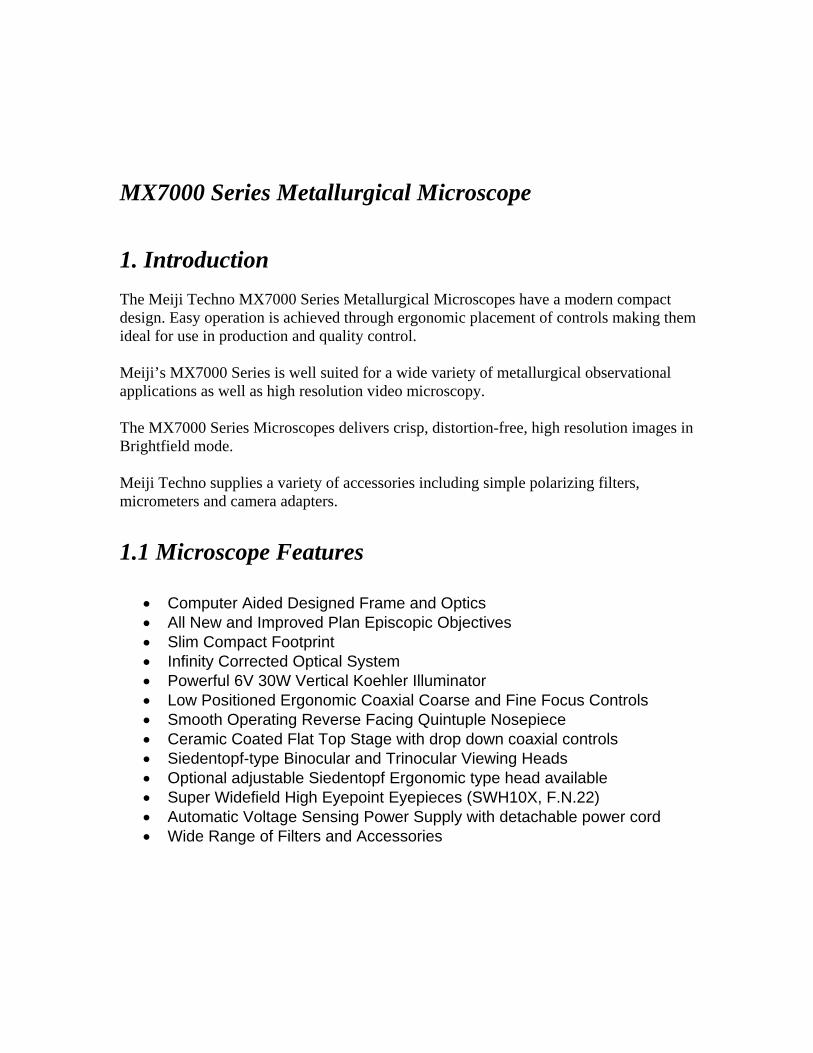
MX7000 Series Metallurgical Microscope
1. Introduction
The Meiji Techno MX7000 Series Metallurgical Microscopes have a modern compact design. Easy operation is achieved through ergonomic placement of controls making them ideal for use in production and quality control. Meiji’s MX7000 Series is well suited for a wide variety of metallurgical observational applications as well as high resolution video microscopy. The MX7000 Series Microscopes delivers crisp, distortion-free, high resolution images in Brightfield mode. Meiji Techno supplies a variety of accessories including simple polarizing filters, micrometers and camera adapters. 1.1 Microscope Features
• Computer Aided Designed Frame and Optics • All New and Improved Plan Episcopic Objectives • Slim Compact Footprint • Infinity Corrected Optical System • Powerful 6V 30W Vertical Koehler Illuminator • Low Positioned Ergonomic Coaxial Coarse and Fine Focus Controls • Smooth Operating Reverse Facing Quintuple Nosepiece • Ceramic Coated Flat Top Stage with drop down coaxial controls • Siedentopf-type Binocular and Trinocular Viewing Heads • Optional adjustable Siedentopf Ergonomic type head available • Super Widefield High Eyepoint Eyepieces (SWH10X, F.N.22) • Automatic Voltage Sensing Power Supply with detachable power cord • Wide Range of Filters and Accessories
1.2 General Safety Guidelines Meiji Techno products are designed for safe operation under normal operating conditions. The instrument and accessories described in this manual have been built and tested according to industry safety standards for electronic laboratory instruments. Incorrect usage or non-conformance to operating instructions can cause personal injury or damage to equipment or property. Keep this manual near your instrument for easy reference. 1.3 Intended Product Use Product Disclaimer: This product is designed and intended for use only as a metallurgical microscope system. Modifying this instrument in any way for use in any situation other than the original and intended product design will automatically void the warranty. In no event shall Meiji Techno be liable to any person or entity for any incidental, indirect or consequential damages, arising out of or in connection with the use or performance of a modified or altered product. 1.4 Product Safety Information- Handling the Microscope
DO NOT OPERATE UNLESS THE UNIT IS PROPERLY GROUNDED! Use only the specified power cord in a well grounded socket. Do not use in an ungrounded power receptacle or in cases where there is a break in the ground conductor or damage to the electrical wiring. Only fuses of the specified type and rating are to be used as replacements. Switch off the power and disconnect the power cord before replacing fuses. Use of a non-compliant fuse may result in electrical shock or severe damage your equipment. Do not replace the bulb for at least 10 minutes after the unit has been turned off or injury may result.
1.5 Warranty Statement Modifying the instrument in any way or unauthorized attempts to disassemble or use the instrument for applications other then its intended design will automatically void the warranty. Meiji Techno warrants this product against defects in material and/or workmanship for the life of the instrument from the date of the original purchase to the original purchaser. Meiji Techno will repair or replace, at its option, any instrument which under normal conditions of use and service proves to be defective in material or workmanship. No charge will be made for labor or materials with respect to defects covered by this warranty, provided all repair work is done by Meiji Techno. This warranty does not cover expenses incurred in the removal or reinstallation of any instrument or instruments, whether or not proven defective. Replacement or repairs furnished under this warranty are subject to the same terms and conditions of the original warranty. This warranty supersedes any other warranty and is subject to the following terms and conditions: WARRANTY Warranty of Meiji Techno’s product extends to the original purchaser of the product and is not transferable. WARRANTY DURATION Meiji Techno warrants this product against defects in material and/or workmanship for the life of the instrument from the date of original purchase to the original purchaser. The electrical warranty is one year. OWNER’S REGISTRATION CARD Return of the owner’s registration card by the original purchaser within ten (10) days after the original purchase is a condition precedent to coverage under this warranty. Meiji Techno will at its option accept written proof of purchase from the original owner in lieu of a product registration card. EXCLUSIONS AND LIMITATIONS Specifically excluded from this warranty are failures caused by abuse, neglect, misuse, improper operation, normal wear, accident, improper maintenance or modifications of ANY type. This warranty does not cover repair or replacement where normal use has exhausted the life of a part or instrument. All mechanical devices need periodic parts replacement and service to perform well. Service life of an instrument is dependent upon the care it receives and the conditions under which it has to operate. In no event shall Meiji Techno be liable for incidental or consequential damages.
SERVICE To obtain service under this warranty, please contact Meiji Techno directly and ask for the Product Service Department. State the nature of the problem, model and serial number of the instrument, date of purchase and location and name of the distributor the instrument was purchased from. After verification of warranty registration, Meiji Techno will issue a return authorization number. Customer may then return the product postage prepaid and insured to the authorized repair facility. In most instances, requests for warranty service will be performed in a prompt and routine manner and merchandise will be returned in a reasonable period of time or at Meiji Techno’s convenience. In some cases, requests for warranty service are received which are not justified. In these cases, Meiji Techno will provide an explanation for non-warranty action. WARRANTY TERMS The terms of this warranty may not be varied by any person, whether or not purporting to represent or act on behalf of Meiji Techno. The limited lifetime warranty provided is in lieu of any and all warranties, expressed or implied, whether for merchantability or fitness for a particular purpose or otherwise. Liability for consequential damages under any, and all warranties are excluded to the extent exclusions are permitted by law. This warranty gives you specific legal rights and you may also have other rights which vary from state to state. This warranty sets forth the customer’s exclusive remedy, with respect to defective products. This limited warranty shall become null and void in the event of a violation of the provisions of this limited warranty.
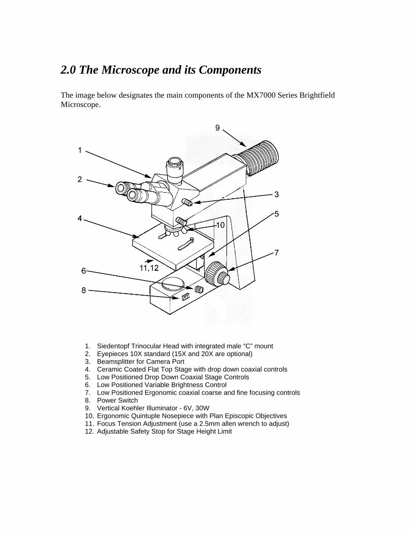
2.0 The Microscope and its Components The image below designates the main components of the MX7000 Series Brightfield Microscope.
1. Siedentopf Trinocular Head with integrated male “C” mount 2. Eyepieces 10X standard (15X and 20X are optional) 3. Beamsplitter for Camera Port 4. Ceramic Coated Flat Top Stage with drop down coaxial controls 5. Low Positioned Drop Down Coaxial Stage Controls 6. Low Positioned Variable Brightness Control 7. Low Positioned Ergonomic coaxial coarse and fine focusing controls 8. Power Switch 9. Vertical Koehler Illuminator - 6V, 30W 10. Ergonomic Quintuple Nosepiece with Plan Episcopic Objectives 11. Focus Tension Adjustment (use a 2.5mm allen wrench to adjust) 12. Adjustable Safety Stop for Stage Height Limit
2.1 Installation Site The microscope should be operated in a room with as little dust as practically possible. Keep your instrument away from solvents, chemical fumes and excessive humidity. Also try to avoid big swings in ambient temperature, direct sunlight and vibration as they can affect measurements and instrument performance. Operating Ambient Conditions Temperature: 10 - 36°C (50 – 96.8°F) Relative Humidity: 0 – 80% up to 30°C (86°F) 2.2 Unpacking Please check your packing slip to insure that all materials are present. Keep a copy for your records so that you have the proper information when ordering more equipment, ordering replacement parts or accessories or when calling for technical support. Please make sure that no small pieces or parts are left in the packing material. Keep the packing materials in a safe place for the purpose of storage and transporting the microscope and its accessories.
Avoid touching the surface of optical components such as lenses, filters and glass surfaces. Even very small traces of perspiration or finger oils can corrode the surfaces of optics in a short period of time.
2.3 Microscope Set Up
• As a first step, remove all components from the shipping container and remove the packing materials and place the microscope frame on a stable work surface.
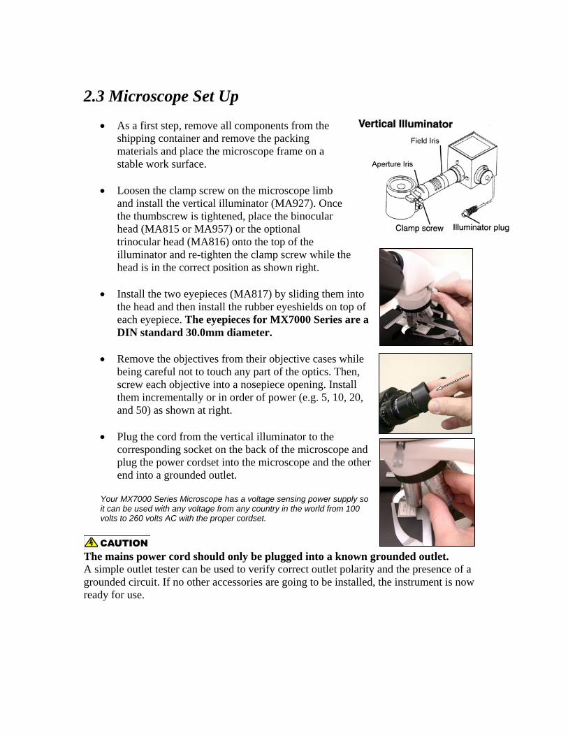
• Loosen the clamp screw on the microscope limb
and install the vertical illuminator (MA927). Once the thumbscrew is tightened, place the binocular head (MA815 or MA957) or the optional trinocular head (MA816) onto the top of the illuminator and re-tighten the clamp screw while the head is in the correct position as shown right.
• Install the two eyepieces (MA817) by sliding them into
the head and then install the rubber eyeshields on top of each eyepiece. The eyepieces for MX7000 Series are a DIN standard 30.0mm diameter.
• Remove the objectives from their objective cases while
being careful not to touch any part of the optics. Then, screw each objective into a nosepiece opening. Install them incrementally or in order of power (e.g. 5, 10, 20, and 50) as shown at right.
• Plug the cord from the vertical illuminator to the
corresponding socket on the back of the microscope and plug the power cordset into the microscope and the other end into a grounded outlet.
Your MX7000 Series Microscope has a voltage sensing power supply so it can be used with any voltage from any country in the world from 100 volts to 260 volts AC with the proper cordset.
The mains power cord should only be plugged into a known grounded outlet. A simple outlet tester can be used to verify correct outlet polarity and the presence of a grounded circuit. If no other accessories are going to be installed, the instrument is now ready for use.
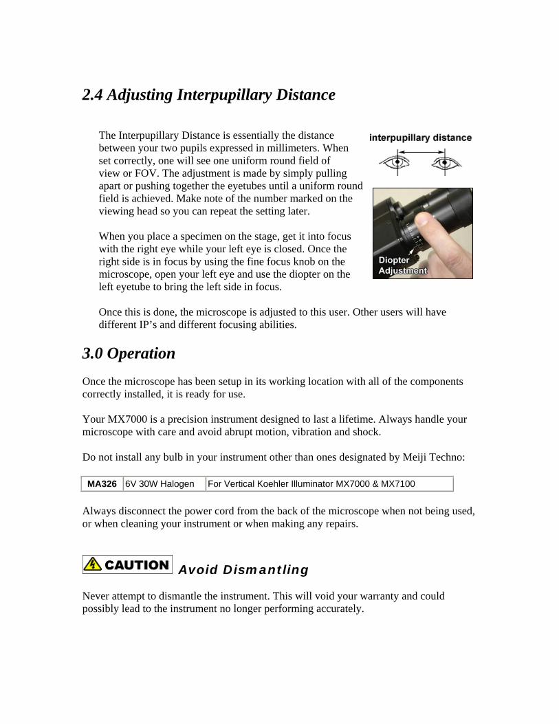
2.4 Adjusting Interpupillary Distance
The Interpupillary Distance is essentially the distance between your two pupils expressed in millimeters. When set correctly, one will see one uniform round field of view or FOV. The adjustment is made by simply pulling apart or pushing together the eyetubes until a uniform round field is achieved. Make note of the number marked on the viewing head so you can repeat the setting later. When you place a specimen on the stage, get it into focus with the right eye while your left eye is closed. Once the right side is in focus by using the fine focus knob on the microscope, open your left eye and use the diopter on the left eyetube to bring the left side in focus. Once this is done, the microscope is adjusted to this user. Other users will have different IP’s and different focusing abilities.
3.0 Operation Once the microscope has been setup in its working location with all of the components correctly installed, it is ready for use. Your MX7000 is a precision instrument designed to last a lifetime. Always handle your microscope with care and avoid abrupt motion, vibration and shock. Do not install any bulb in your instrument other than ones designated by Meiji Techno: MA326 6V 30W Halogen For Vertical Koehler Illuminator MX7000 & MX7100
Always disconnect the power cord from the back of the microscope when not being used, or when cleaning your instrument or when making any repairs.
Avoid Dismantling Never attempt to dismantle the instrument. This will void your warranty and could possibly lead to the instrument no longer performing accurately.

3.1 Centering the Lamp – Incident Illuminator Your light source may need to be “centered” if the field of view seems unevenly illuminated. The centering controls are located on the side of the light source housing at the back end of the vertical illuminator. The drawing below shows the location of the controls. Centering Adjustment
1. Adjust the brightness to a comfortable level with no specimen on the stage.
2. Loosen the screw on the vertical adjustment and while looking into the eyetubes, center the bulb vertically in the field of view and then re-tighten the screw while the bulb filament is in the correct position.
3. While continuing to look into the eyetubes, center the bulb filament in the field of
view by using the knob to attain centering in the left-right position. This adjustment will also need to be done whenever the bulb is changed.
3.2 Incident Light Operation – Brightfield
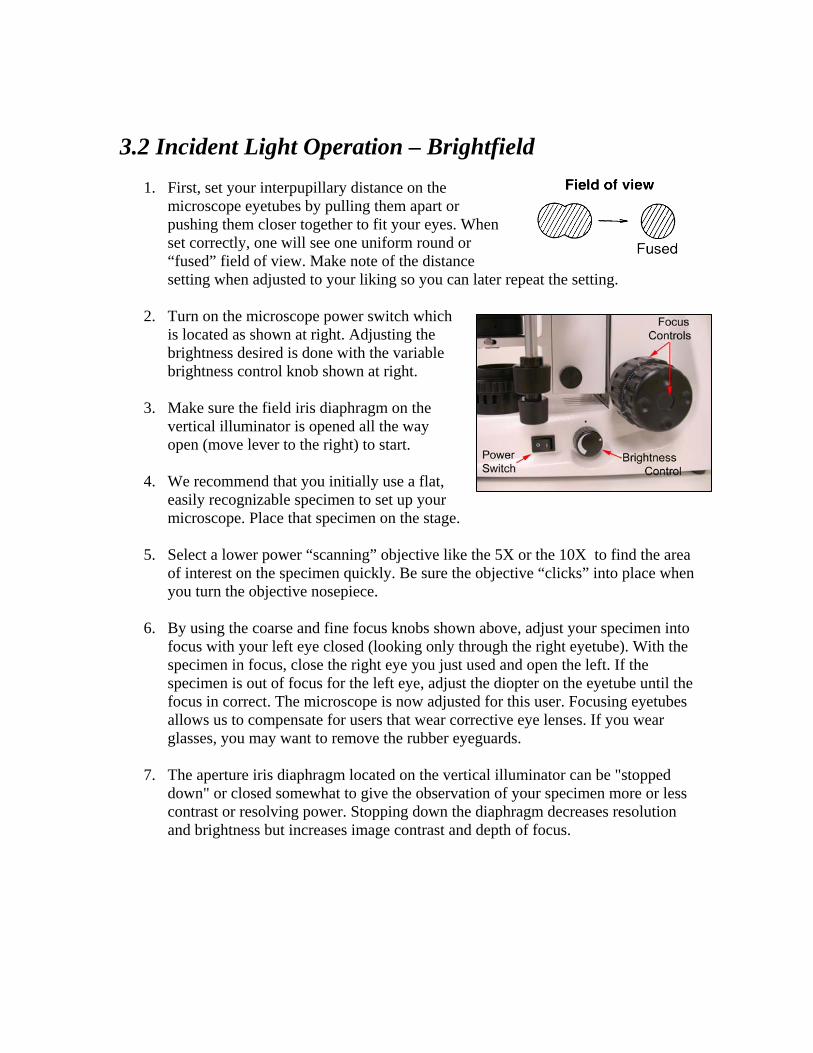
1. First, set your interpupillary distance on the microscope eyetubes by pulling them apart or pushing them closer together to fit your eyes. When set correctly, one will see one uniform round or “fused” field of view. Make note of the distance setting when adjusted to your liking so you can later repeat the setting.
2. Turn on the microscope power switch which
is located as shown at right. Adjusting the brightness desired is done with the variable brightness control knob shown at right.
3. Make sure the field iris diaphragm on the
vertical illuminator is opened all the way open (move lever to the right) to start.
4. We recommend that you initially use a flat,
easily recognizable specimen to set up your microscope. Place that specimen on the stage.
5. Select a lower power “scanning” objective like the 5X or the 10X to find the area
of interest on the specimen quickly. Be sure the objective “clicks” into place when you turn the objective nosepiece.
6. By using the coarse and fine focus knobs shown above, adjust your specimen into
focus with your left eye closed (looking only through the right eyetube). With the specimen in focus, close the right eye you just used and open the left. If the specimen is out of focus for the left eye, adjust the diopter on the eyetube until the focus in correct. The microscope is now adjusted for this user. Focusing eyetubes allows us to compensate for users that wear corrective eye lenses. If you wear glasses, you may want to remove the rubber eyeguards.
7. The aperture iris diaphragm located on the vertical illuminator can be "stopped
down" or closed somewhat to give the observation of your specimen more or less contrast or resolving power. Stopping down the diaphragm decreases resolution and brightness but increases image contrast and depth of focus.

Possible Brightfield Mode Operational Problems If normal adjustments are not getting the results you expect, check to see if these conditions exist:
• Incorrect components inadvertently installed • Components not mounted flush (Vertical Illuminator to microscope frame, etc.) • Dirty or smudged optics
MX7000 Series Plan Episcopic Brightfield Objectives
Brightfield Objectives – Plan Episcopic - Infinity Corrected - F = 200mm MA870 Plan Epi 5X objective, NA: 0.10, WD = 20.0mm (included)
MA871 Plan Epi 10X objective, NA: 0.25, WD = 7.48mm (included) MA872 Plan Epi 20X, objective, NA: 0.40, WD = 5.20mm (optional) MA873 MA874
Plan Epi 50X objective, NA: 0.75, WD = 0.38mm (included) Plan Epi 100X oil objective, NA: 0.90, WD = 0.37mm (optional)
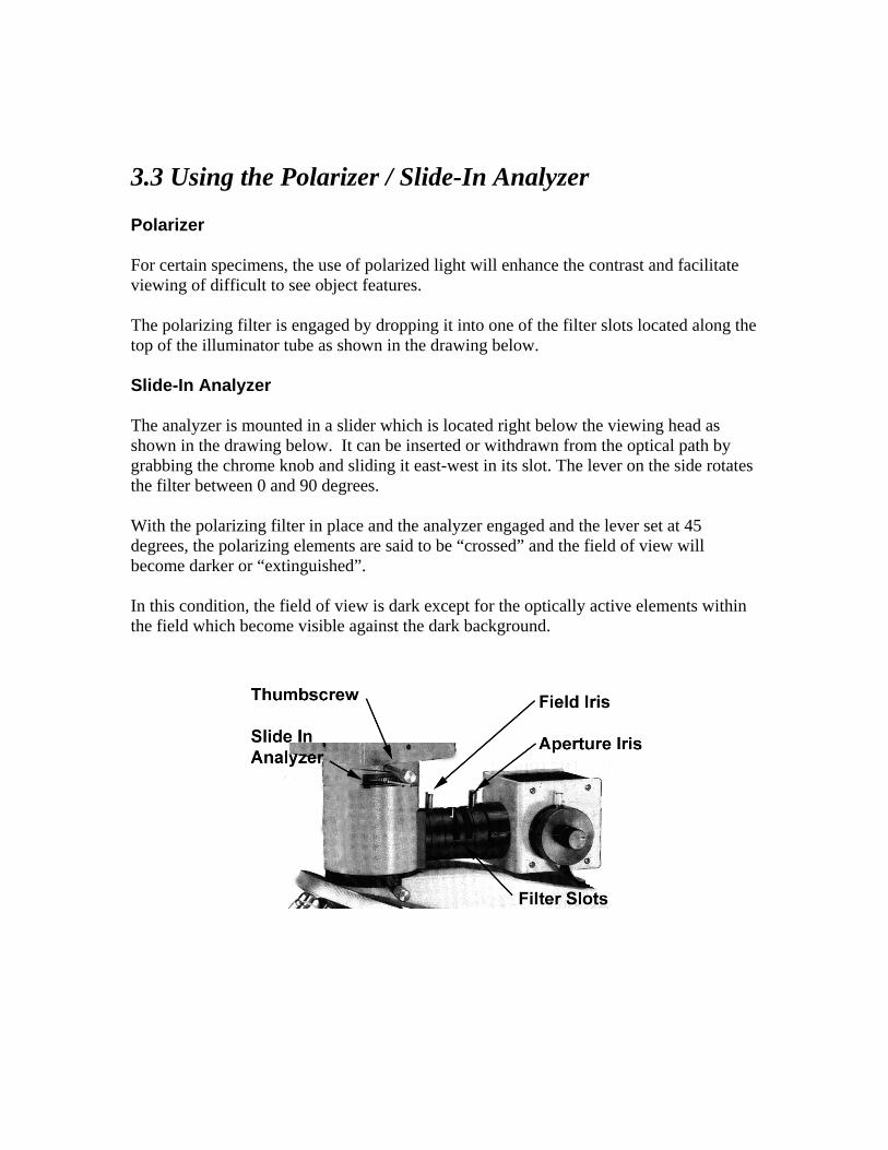
3.3 Using the Polarizer / Slide-In Analyzer Polarizer For certain specimens, the use of polarized light will enhance the contrast and facilitate viewing of difficult to see object features. The polarizing filter is engaged by dropping it into one of the filter slots located along the top of the illuminator tube as shown in the drawing below. Slide-In Analyzer The analyzer is mounted in a slider which is located right below the viewing head as shown in the drawing below. It can be inserted or withdrawn from the optical path by grabbing the chrome knob and sliding it east-west in its slot. The lever on the side rotates the filter between 0 and 90 degrees. With the polarizing filter in place and the analyzer engaged and the lever set at 45 degrees, the polarizing elements are said to be “crossed” and the field of view will become darker or “extinguished”. In this condition, the field of view is dark except for the optically active elements within the field which become visible against the dark background.
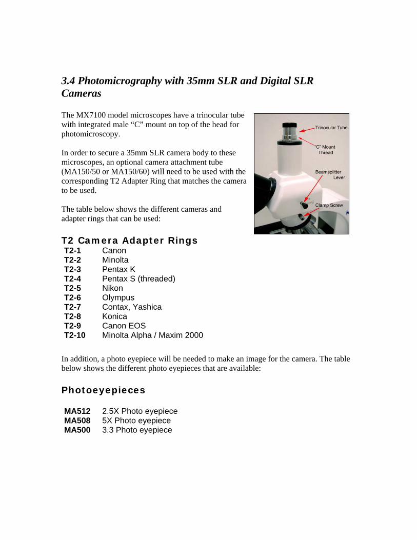
3.4 Photomicrography with 35mm SLR and Digital SLR Cameras The MX7100 model microscopes have a trinocular tube with integrated male “C” mount on top of the head for photomicroscopy. In order to secure a 35mm SLR camera body to these microscopes, an optional camera attachment tube (MA150/50 or MA150/60) will need to be used with the corresponding T2 Adapter Ring that matches the camera to be used. The table below shows the different cameras and adapter rings that can be used: T2 Camera Adapter Rings T2-1 T2-2 T2-3 T2-4 T2-5 T2-6 T2-7 T2-8 T2-9 T2-10
Canon Minolta Pentax K Pentax S (threaded) Nikon Olympus Contax, Yashica Konica Canon EOS Minolta Alpha / Maxim 2000
In addition, a photo eyepiece will be needed to make an image for the camera. The table below shows the different photo eyepieces that are available: Photoeyepieces MA512 MA508 MA500
2.5X Photo eyepiece 5X Photo eyepiece 3.3 Photo eyepiece
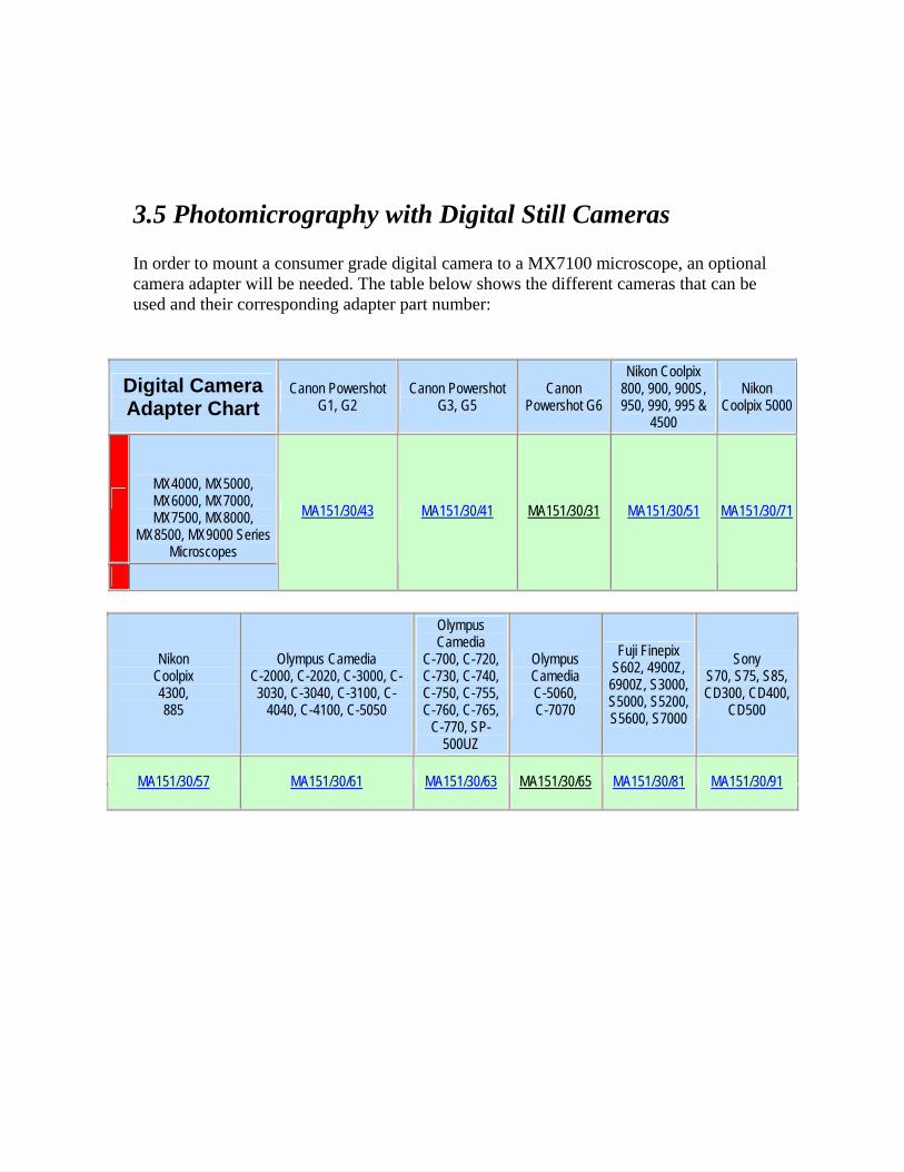
3.5 Photomicrography with Digital Still Cameras In order to mount a consumer grade digital camera to a MX7100 microscope, an optional camera adapter will be needed. The table below shows the different cameras that can be used and their corresponding adapter part number:
Digital Camera Adapter Chart
Canon Powershot G1, G2
Canon Powershot G3, G5
Canon Powershot G6
Nikon Coolpix 800, 900, 900S, 950, 990, 995 &
4500
Nikon Coolpix 5000
MX4000, MX5000, MX6000, MX7000, MX7500, MX8000,
MX8500, MX9000 Series Microscopes
MA151/30/43 MA151/30/41 MA151/30/31 MA151/30/51 MA151/30/71
Nikon Coolpix 4300, 885
Olympus Camedia C-2000, C-2020, C-3000, C-3030, C-3040, C-3100, C-
4040, C-4100, C-5050
Olympus Camedia
C-700, C-720, C-730, C-740, C-750, C-755, C-760, C-765,
C-770, SP-500UZ
Olympus Camedia C-5060, C-7070
Fuji Finepix S602, 4900Z, 6900Z, S3000, S5000, S5200, S5600, S7000
Sony S70, S75, S85, CD300, CD400,
CD500
MA151/30/57 MA151/30/61 MA151/30/63 MA151/30/65 MA151/30/81 MA151/30/91
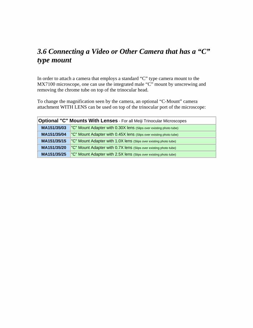
3.6 Connecting a Video or Other Camera that has a “C” type mount In order to attach a camera that employs a standard “C” type camera mount to the MX7100 microscope, one can use the integrated male “C” mount by unscrewing and removing the chrome tube on top of the trinocular head. To change the magnification seen by the camera, an optional “C-Mount” camera attachment WITH LENS can be used on top of the trinocular port of the microscope: Optional "C" Mounts With Lenses - For all Meiji Trinocular Microscopes
MA151/35/03 "C" Mount Adapter with 0.30X lens (Slips over existing photo tube) MA151/35/04 "C" Mount Adapter with 0.45X lens (Slips over existing photo tube) MA151/35/15 "C" Mount Adapter with 1.0X lens (Slips over existing photo tube) MA151/35/20 "C" Mount Adapter with 0.7X lens (Slips over existing photo tube) MA151/35/25 "C" Mount Adapter with 2.5X lens (Slips over existing photo tube)

4.0 Maintenance and Cleaning
• Disconnect the power cord on your equipment prior to performing cleaning, maintenance or repair.
• Keep electrical components away from moisture or humidity.
• In warm humid climates, take special care to prevent your equipment from
exposure to fungal growth by using desiccant in an airtight storage container or by other means.
• Clean the microscope after each use. Keeping your microscope clean will insure
its proper operation over its lifetime. Dust Protection Be sure to use the supplied dust cover with your microscope after each work session. Cleaning Dust, fibers and other debris can cause your field of view to get obstructed so keeping your microscope clean will help the overall quality of your work. Cleaning of Painted Surfaces Use a soft brush or lint-free cotton cloth to removed dust and loose particles. Tough dirt can be removed with water and a mild detergent.
NEVER USE ACETONE OR OTHER HARSH CHEMICALS.
Painted or plastic surfaces should not be tarnished or etched with cleaning agents that are too powerful. To clean painted surfaces, use a moistened lint-free cotton cloth with mild soapy water.
Cleaning the Stage Use a soft brush or lint-free cotton cloth to removed dust and loose particles. DO NOT USE ACETONE OR OTHER HARSH CHEMICALS, use a moistened lint-free cotton cloth with a solution of mild soapy water. Cleaning of Glass Surfaces Use a soft brush or lint-free cotton cloth to removed dust and loose particles. For tough dirt, use a soft lint-free cotton cloth moistened with distilled water. If that fails, try using medical or reagent grade isopropyl alcohol. Cleaning the Objectives
Objectives should NEVER be disassembled for cleaning or for any other reason! We do not advise cleaning the inside surfaces of objectives or eyepieces. Use a soft brush, bellows brush or a soft lint-free cotton cloth to removed dust and loose particles. For tough dirt, use a soft lint-free cotton cloth moistened with distilled water. If that fails, carefully try using medical or reagent grade isopropyl alcohol. Wipe lenses immediately. Over time, water and solvents can dissolve optical cements that hold optics together so NEVER soak objectives with ANY type of fluid.

5.0 Troubleshooting Meiji Techno products are manufactured exclusively in Japan under ISO9001 manufacturing standards. However, if you ever have any difficulty with any Meiji product, feel free to contact us at: MEIJI TECHNO CO., LTD. 322-1, Chikumazawa, Miyoshi machi, Iruma-gun Saitama 354-0043, Japan
Phone: Fax: E-mail: Web:
049-259-0111 049-259-0113 [email protected] http://www.meijitechno.co.jp
Meiji Techno America 3010 Olcott Street Santa Clara, CA 95054-3207
Phone: Fax: E-mail: Web:
800.832.0060 408.970.5054 FAX [email protected]://www.meijitechno.com
Our technical staff is trained to assist you on mechanical or electrical issues you may have. Operational Issues Please refer to the previous “Operations” chapters which coincide with the observation mode that you are using. The most common operational problems include the improper positioning of contrast accessories, the improper adjustment or the incorrect parts installed. If you are unable to obtain the desired image from the microscope, please refer to the corresponding chapters of this manual under the proper operation mode: brightfield, etc. Electrical Problems Electrical problems can include:
• The lamp on the microscope is not working. • No voltage is present.
Check the following probable causes:
• Check that all power cords are properly connected to the right spots. • Make sure power is actually present at the wall outlet. • Check to see if there is a fuse is blown.
5.1 Replacing the mains fuse on the microscope
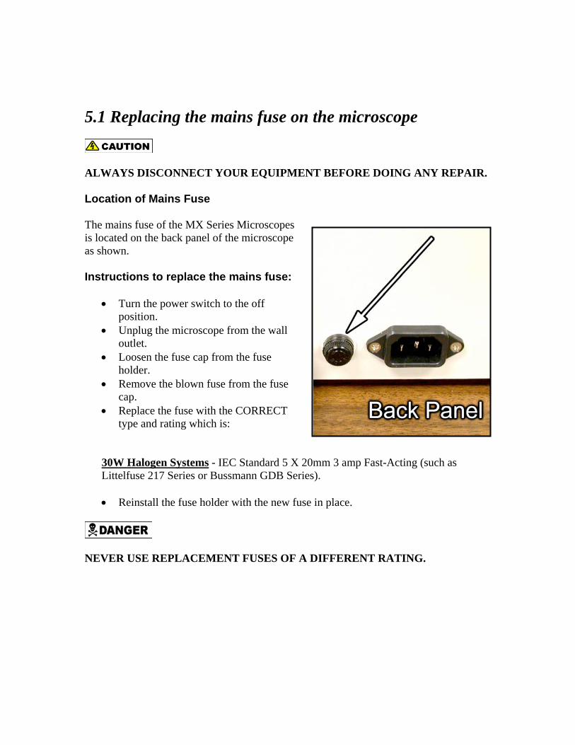
ALWAYS DISCONNECT YOUR EQUIPMENT BEFORE DOING ANY REPAIR. Location of Mains Fuse The mains fuse of the MX Series Microscopes is located on the back panel of the microscope as shown. Instructions to replace the mains fuse:
• Turn the power switch to the off position.
• Unplug the microscope from the wall outlet.
• Loosen the fuse cap from the fuse holder.
• Remove the blown fuse from the fuse cap.
• Replace the fuse with the CORRECT type and rating which is:
30W Halogen Systems - IEC Standard 5 X 20mm 3 amp Fast-Acting (such as Littelfuse 217 Series or Bussmann GDB Series). • Reinstall the fuse holder with the new fuse in place.
NEVER USE REPLACEMENT FUSES OF A DIFFERENT RATING.
5.2 Incident Light does not work
• Make sure your mains outlet indeed has power. • Make sure the plug from the lamp is firmly plugged into the correct socket on the
rear panel. • Check to see if the mains fuse has blown. • Check to see if the lamp has blown.
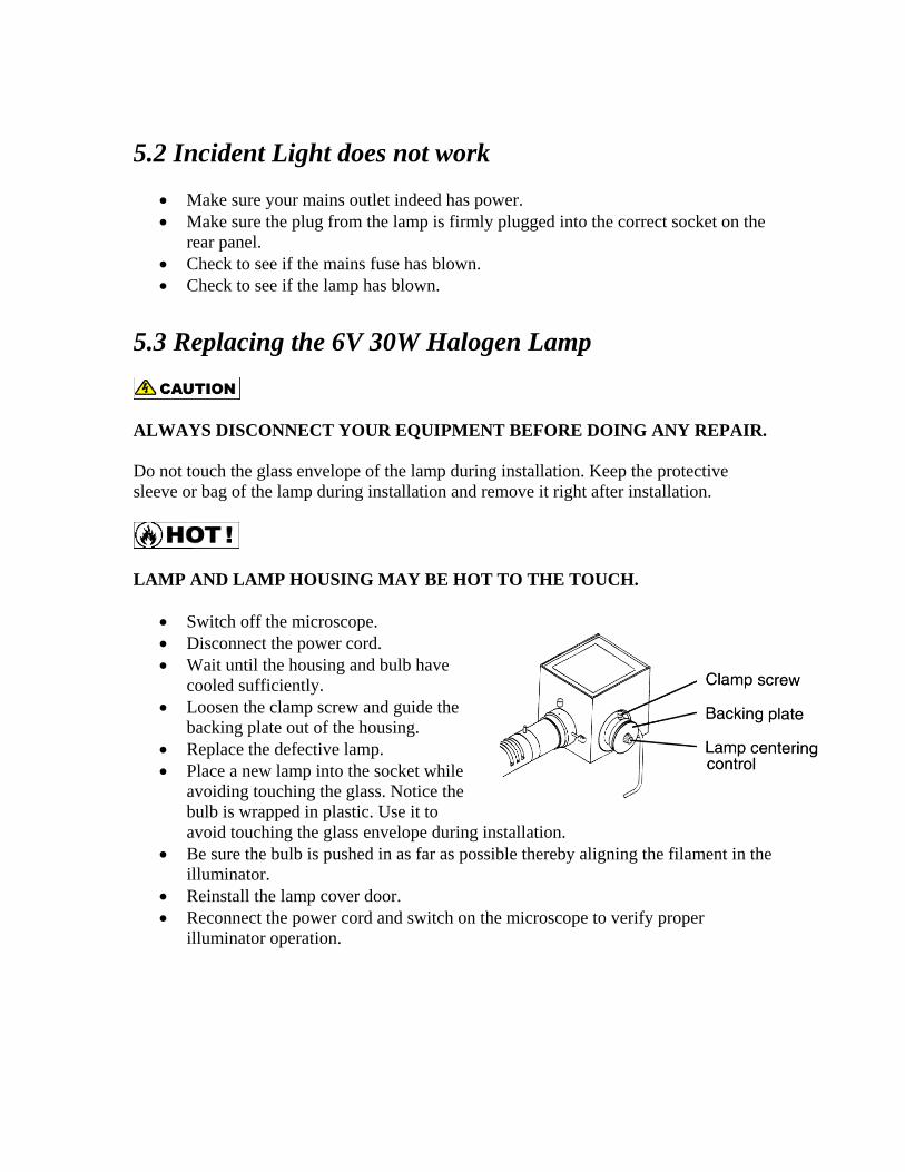
5.3 Replacing the 6V 30W Halogen Lamp
ALWAYS DISCONNECT YOUR EQUIPMENT BEFORE DOING ANY REPAIR. Do not touch the glass envelope of the lamp during installation. Keep the protective sleeve or bag of the lamp during installation and remove it right after installation.
LAMP AND LAMP HOUSING MAY BE HOT TO THE TOUCH.
• Switch off the microscope. • Disconnect the power cord. • Wait until the housing and bulb have
cooled sufficiently. • Loosen the clamp screw and guide the
backing plate out of the housing. • Replace the defective lamp. • Place a new lamp into the socket while
avoiding touching the glass. Notice the bulb is wrapped in plastic. Use it to avoid touching the glass envelope during installation.
• Be sure the bulb is pushed in as far as possible thereby aligning the filament in the illuminator.
• Reinstall the lamp cover door. • Reconnect the power cord and switch on the microscope to verify proper
illuminator operation.

6.0 Storage
• Protect your microscope from dust after each use by covering your instrument with the protective dust cover that came with your microscope.
• Store your microscope in a cabinet that has a stable temperature and low
humidity.
• If you live in an area that has high humidity, consider storing your microscope in a sealed container along with a desiccant such as silica gel.
• It is also recommended that the objective and eyepieces be stored in a separate air
tight container with desiccant. 7.0 Packing and Transport
• Whenever the microscope is going to be moved, ship or transport the microscope and the accessories in its original packing.
• It is advisable to keep a copy of all necessary information: copy of the original
invoice, the operations manual, etc. included with the microscope when shipping.
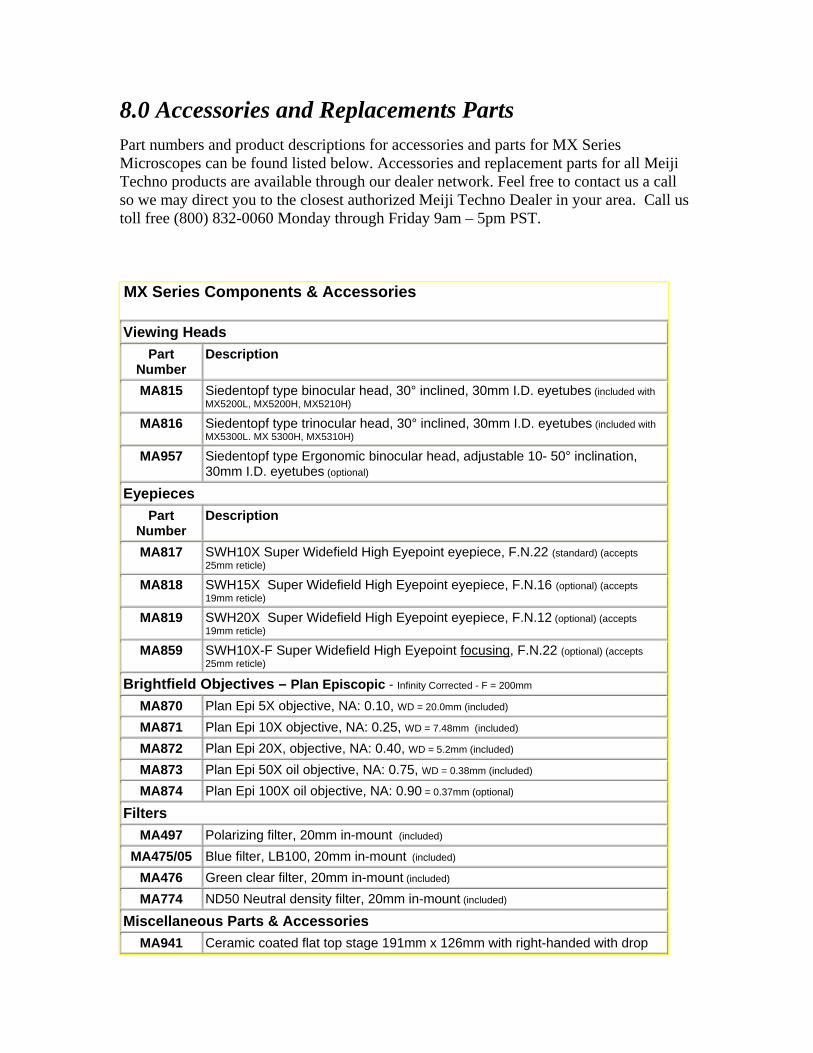
8.0 Accessories and Replacements Parts Part numbers and product descriptions for accessories and parts for MX Series Microscopes can be found listed below. Accessories and replacement parts for all Meiji Techno products are available through our dealer network. Feel free to contact us a call so we may direct you to the closest authorized Meiji Techno Dealer in your area. Call us toll free (800) 832-0060 Monday through Friday 9am – 5pm PST.
MX Series Components & Accessories
Viewing Heads Part
Number Description
MA815 Siedentopf type binocular head, 30° inclined, 30mm I.D. eyetubes (included with MX5200L, MX5200H, MX5210H)
MA816 Siedentopf type trinocular head, 30° inclined, 30mm I.D. eyetubes (included with MX5300L. MX 5300H, MX5310H)
MA957 Siedentopf type Ergonomic binocular head, adjustable 10- 50° inclination, 30mm I.D. eyetubes (optional)
Eyepieces Part
Number Description
MA817 SWH10X Super Widefield High Eyepoint eyepiece, F.N.22 (standard) (accepts 25mm reticle)
MA818 SWH15X Super Widefield High Eyepoint eyepiece, F.N.16 (optional) (accepts 19mm reticle)
MA819 SWH20X Super Widefield High Eyepoint eyepiece, F.N.12 (optional) (accepts 19mm reticle)
MA859 SWH10X-F Super Widefield High Eyepoint focusing, F.N.22 (optional) (accepts 25mm reticle)
Brightfield Objectives – Plan Episcopic - Infinity Corrected - F = 200mm MA870 Plan Epi 5X objective, NA: 0.10, WD = 20.0mm (included)
MA871 Plan Epi 10X objective, NA: 0.25, WD = 7.48mm (included) MA872 Plan Epi 20X, objective, NA: 0.40, WD = 5.2mm (included) MA873 Plan Epi 50X oil objective, NA: 0.75, WD = 0.38mm (included) MA874 Plan Epi 100X oil objective, NA: 0.90 = 0.37mm (optional)
Filters MA497 Polarizing filter, 20mm in-mount (included)
MA475/05 Blue filter, LB100, 20mm in-mount (included) MA476 Green clear filter, 20mm in-mount (included) MA774 ND50 Neutral density filter, 20mm in-mount (included)
Miscellaneous Parts & Accessories MA941 Ceramic coated flat top stage 191mm x 126mm with right-handed with drop
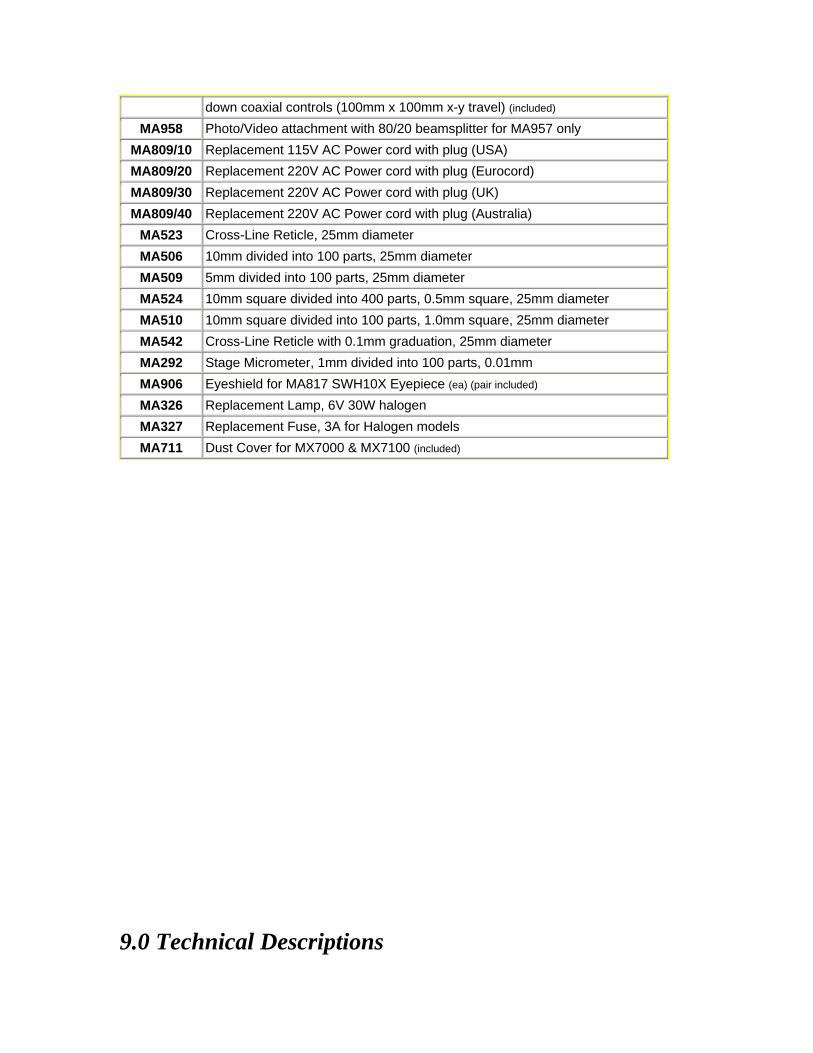
down coaxial controls (100mm x 100mm x-y travel) (included) MA958 Photo/Video attachment with 80/20 beamsplitter for MA957 only
MA809/10 Replacement 115V AC Power cord with plug (USA) MA809/20 Replacement 220V AC Power cord with plug (Eurocord) MA809/30 Replacement 220V AC Power cord with plug (UK) MA809/40 Replacement 220V AC Power cord with plug (Australia)
MA523 Cross-Line Reticle, 25mm diameter MA506 10mm divided into 100 parts, 25mm diameter MA509 5mm divided into 100 parts, 25mm diameter MA524 10mm square divided into 400 parts, 0.5mm square, 25mm diameter MA510 10mm square divided into 100 parts, 1.0mm square, 25mm diameter MA542 Cross-Line Reticle with 0.1mm graduation, 25mm diameter MA292 Stage Micrometer, 1mm divided into 100 parts, 0.01mm MA906 Eyeshield for MA817 SWH10X Eyepiece (ea) (pair included) MA326 Replacement Lamp, 6V 30W halogen MA327 Replacement Fuse, 3A for Halogen models MA711 Dust Cover for MX7000 & MX7100 (included)
9.0 Technical Descriptions
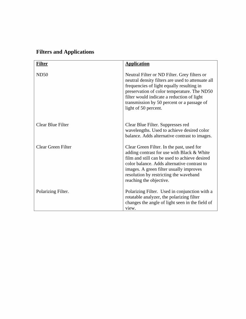
Filters and Applications Filter ND50 Clear Blue Filter Clear Green Filter Polarizing Filter.
Application Neutral Filter or ND Filter. Grey filters or neutral density filters are used to attenuate all frequencies of light equally resulting in preservation of color temperature. The ND50 filter would indicate a reduction of light transmission by 50 percent or a passage of light of 50 percent. Clear Blue Filter. Suppresses red wavelengths. Used to achieve desired color balance. Adds alternative contrast to images. Clear Green Filter. In the past, used for adding contrast for use with Black & White film and still can be used to achieve desired color balance. Adds alternative contrast to images. A green filter usually improves resolution by restricting the waveband reaching the objective. Polarizing Filter. Used in conjunction with a rotatable analyzer, the polarizing filter changes the angle of light seen in the field of view.

10.0 Physical Dimensions
Meiji Techno Co. Ltd. MEIJI TECHNO CO., LTD. 322-1, Chikumazawa, Miyoshi machi, Iruma-gun Saitama 354-0043, Japan
Phone: Fax: Email: Web:
049-259-0111 049-259-0113 [email protected]://www.meijit echno.co.jp
MEIJI TECHNO AMERICA 3010 Olcott Street Santa Clara, CA 95054-3207
Toll free: Phone: Fax: E-mail: Web:
(800) 832-0060 (408) 970-4799 (408) 970.5054 [email protected]://www.meijitechno.com
MEIJI TECHNO UK, LTD. The Vineyard, Axbridge Somerset, BS26 2AN
Phone: Fax: Email: Web:
01934 733655 01934 733660 [email protected]://www.meijitechno.co.uk