Embed Size (px)
Citation preview

Caution: Federal law (U.S.) restricts this device to sale by or on the order of a physician.
To contact Mallinckrodt�s representative: In the United States, call 1.800.635.5267or 314.654.2000; outside of the United States, call your local Mallinckrodt representative.
2000 Mallinckrodt Inc. All rights reserved. 062988A-1000
OPERATOR�S MANUAL
N-395 Pulse Oximeter

Mallinckrodt Inc.675 McDonnell BoulevardP.O. Box 5980St. Louis, MO 63134Telephone 314.654.2000Toll Free 1.800.635.5267
MallinckrodtEurope BVHambakenwetering 15231 DD�s-HertogenboschThe NetherlandsTel +31.73.6485200
Nellcor Puritan Bennett Inc.4280 Hacienda DrivePleasanton, CA 94588
Nellcor Puritan Bennett Inc. is a wholly owned subsidiary of Mallinckrodt, Inc. Nellcor andNellcor Puritan Bennett are trademarks of Mallinckrodt Inc.
To obtain information about a warranty, if any, for this product, contact MallinckrodtTechnical Services Department, or your local Mallinckrodt representative.
Purchase of this instrument confers no express or implied license under any Mallinckrodtpatent to use the instrument with any sensor that is not manufactured or licensed byMallinckrodt.
The following are trademarks of Mallinckrodt Inc.: Durasensor, Oxisensor II, Oxinet, Dura-Y, Oxiband, and Oxicliq.
Covered by one or more of the following U.S. Patents and foreign equivalents: 4,621,643;4,653,498; 4,700,708; 4,770,179; Re.35,122; 4,928,692; 4,934,372; 5,351,685; 5,368,026;5,485,847; 5,533,507, and 5,662,106.
www.mallinckrodt.com

iii
CONTENTSFiguresTables
Contents ................................................................................... iiiFigures ................................................................................viiTables ................................................................................viii
Safety Information.......................................................................1General Safety Information .................................................. 1
Introduction .................................................................................3Intended Use........................................................................ 3General Operating Principles and Conditions...................... 3
Controls, Indicators, And Symbols ...........................................5Displays, Controls, Indicators, and Connectors ................... 5N-395 Symbols..................................................................... 6Description of Controls......................................................... 7
Function Buttons....................................................... 7Description of Displays and Visual Indicators ...................... 8Description of Audible Indicators ......................................... 9
Setup ..................................................................................11Unpacking and Inspection.................................................. 11Performance Verification ................................................... 11List Of Components ........................................................... 11
Optional Accessories.............................................. 12Monitor Setup..................................................................... 18
General Warnings .................................................. 18Connecting The N-395 To AC Power..................... 19Operating on a Discharged Battery ........................ 19
Language Selection ........................................................... 21Sensors ..................................................................................23
Selecting a Sensor............................................................. 23Biocompatibility Testing ..................................................... 24Performance Considerations ............................................. 25
Start-Up and Use .......................................................................27Basic Operation ................................................................. 27
Power-On Self-Test (POST)................................... 28Adult-Pediatric and Neonatal Settings.................... 30Contrast .................................................................. 31Monitoring Mode..................................................... 31Pulse Search .......................................................... 32
Contents
iv
At Initial Power-Up(Sensor Attached to Monitor) .....................32
At Initial Power-Up(No Sensor Attached to Monitor)................32
After Taking Measurements....................................33Sensor Disconnected..............................................33Sensor Off...............................................................33Automatic Shutdown ...............................................33
Alarms ................................................................................34Description of Alarms..............................................34Satseconds Alarm Management.............................35Satseconds "Safety Net" .........................................37Determining the Satseconds...................................37Satseconds Display.................................................38
Adjustable Settings.............................................................38Pulse Beep Volume ................................................38Alarm Volume .........................................................39Alarm Silence Duration ...........................................39Disabling Audible Alarms ........................................40Alarm Silence Reminder .........................................40
Menu...................................................................................41Menu Structure .......................................................41
Limits ..................................................................................42Overview .................................................................42Viewing Current Alarm Limits..................................42Changing Alarm Limits............................................43Alarm Limits Changed Indicator..............................46
Trend ..................................................................................46View ...................................................................48Zoom ...................................................................5040-Second Trends Table ........................................50Next ...................................................................51Delete ...................................................................51Print ...................................................................51
Setup ..................................................................................52View ...................................................................52Clock ...................................................................52Comm ...................................................................53Lang ...................................................................57Ncall ...................................................................58Analog ...................................................................58Light ...................................................................58

Contents
v
Default Settings ...................................................... 58Nurse Call Feature ................................................. 60
Battery Operation ............................................................... 61Low Battery Indicator .............................................. 61
Disposal Of Device Components....................................... 62Performance Considerations ............................................. 62
Impact of Patient Conditions onMonitor Readings....................................... 62
Troubleshooting And Maintenance .........................................65Troubleshooting ................................................................. 65
Error Codes ............................................................ 65Other Messages ..................................................... 66Suggested Corrective Actions ................................ 67
EMI (Electromagnetic Interference) ................................... 70Obtaining Technical Assistance......................................... 71Returning the N-395........................................................... 71Maintenance ...................................................................... 71
Service ................................................................... 71Periodic Safety Checks .......................................... 72Performance Verification ........................................ 72Cleaning ................................................................. 72
Specifications ............................................................................73Performance ...................................................................... 73
Measurement Range.............................................. 73Accuracy................................................................. 73
Electrical ............................................................................ 74Instrument .............................................................. 74Battery ................................................................... 74
Environmental Conditions .................................................. 75Transport And Storage (in Shipping Container) ..... 75Transport And Storage
(Not in Shipping Container) ....................... 75Operation................................................................ 75
Physical Characteristics..................................................... 75Compliance ........................................................................ 76
Quick Guide to Operation.........................................................77Introduction ........................................................................ 77Settings Adjustments ......................................................... 77
Principles of Operation.............................................................83Oximetry Overview............................................................. 83
Automatic Calibration ............................................. 83Functional versus Fractional Saturation ................. 84

Contents
vi
Measured versus Calculated Saturation .................84Data Port Protocol .....................................................................87
Overview.............................................................................87Connecting to the Data Port ...............................................87Baud Rate...........................................................................89Setting Data Port Protocol ..................................................89Real-Time Display Format..................................................90
Column Headings ...................................................91Patient Data and Operating Status .........................93
Trend Data Printout (ASCII Mode) .....................................94Trend Data Printout (Graph Mode).....................................95Nurse Call...........................................................................95Analog Outputs...................................................................97
Index ..................................................................................99

Contents
vii
FIGURESFigure 1: N-395 Front Panel Display (Pleth View) ...................... 5Figure 2: N-395 Rear Panel ........................................................ 6Figure 3: GCX Mounting Plate .................................................. 13Figure 4: GCX Poly-mount (vertical wall mount
with 19-inch channel)............................................... 14Figure 5: GCX Poly-mount (horizontal wall mount
with rail adapter) ....................................................... 15Figure 6: GCX Roll Stand Poly-mount ...................................... 16Figure 7: GCX Utility Basket ..................................................... 17Figure 8: Soft Sided Carrying Case .......................................... 18Figure 9: Monitoring Mode Display - Pleth View ....................... 30Figure 10: Monitoring Mode Display � Blip (Magnified) View..... 30Figure 11: Alarm Response with SatSeconds ............................ 36Figure 12: Alarm Limits Selection ............................................... 46Figure 13: SpO2 Trend ............................................................... 47Figure 14: Dual Trend Display .................................................... 48Figure 15: SpO2 Trend Display .................................................. 49Figure 16: Pulse Rate Trend Display.......................................... 49Figure 17: Histogram .................................................................. 50Figure 18: AMP Trend Display.................................................... 50Figure 19: 40-Second Trends ..................................................... 51Figure 20: SpaceLabs Connection.............................................. 55Figure 21: Oxyhemoglobin Dissociation Curve........................... 85Figure 22: Data Port Pin Layout.................................................. 89Figure 23: Real-Time Printout..................................................... 91Figure 24: Trend Data Printout (ASCII MODE)........................... 95Figure 25: Trend Data Printout (GRAPH MODE) ....................... 95

Contents
viii
TABLESTable 1: Nellcor Sensors ...........................................................24Table 2: Limits Menu .................................................................43Table 3: Trend Menu .................................................................44Table 4: Setup Menu .................................................................45Table 5: Trend Scale .................................................................47Table 6: Factory Default Settings (Adult) ..................................59Table 7: Factory Default Settings (Neonate) .............................60Table 8: Error Codes and Messages.........................................66Table 9: Settings Adjustments...................................................77Table 10: Data Port Pinouts ........................................................88Table 11: Status Codes...............................................................94Table 12: Voltage Between Pins 10 and 11 ................................96Table 13: Analog Pinouts ............................................................97

1
SAFETY INFORMATIONGeneral Safety Information
GENERAL SAFETY INFORMATION
This section contains important safety information related togeneral use of the N-395 pulse oximeter. Other important safetyinformation appears throughout the manual in sections that relatespecifically to the precautionary information. Read all textsurrounding all precautionary information.
Important! Before use, carefully read this manual, accessorydirections for use, all precautionary information in boldface type,and specifications.
WARNING: Explosion hazard. Do not use the N-395 pulseoximeter in the presence of flammable anesthetics or gases.
WARNING: The N-395 is a prescription device and is to beoperated by qualified personnel only.
WARNING: Pulse oximetry readings and pulse signal can beaffected by certain ambient environmental conditions, sensorapplication errors, and certain patient conditions. See theappropriate sections of the manual for specific safetyinformation.
WARNING: Chemicals from a broken LCD display panelare toxic when ingested. Use caution when handling amonitor with a broken display panel.
Caution: When connecting the N-395 to any instrument,verify proper operation before clinical use. Both the N-395and the instrument connected to it must be connected to agrounded outlet. Accessory equipment connected to themonitor�s data interface must be certified according to IECStandard 950 for data-processing equipment or IECStandard 601-1 for electromedical equipment. All

Safety Information
2
combinations of equipment must be in compliance with IECStandard 601-1-1 systems requirements. Anyone whoconnects additional equipment to the signal input port orsignal output port (N-395 data port connector) configures amedical system and is therefore responsible for ensuring thatthe system complies with the requirements of systemstandard IEC Standard 601-1-1 and the electromagneticcompatibility system standard IEC Standard 601-1-2. TheN-395 accuracy may degrade if it is connected to secondaryI/O devices when the instrument is not connected to earthreference.
To ensure accurate readings, consider the environmentalconditions that are present and the condition of the patient. Seethe appropriate sections of the manual for specific safetyinformation related to these conditions.

3
INTRODUCTIONIntended UseGeneral Operating Principles and Conditions
The latest version of this manual is available on the Internet at:http://www.mallinckrodt.com/respiratory/resp/Serv_Supp/ProductManuals.html
INTENDED USE
The N-395 is a portable pulse oximeter intended for use as acontinuous non-invasive monitor of functional oxygen saturationof arterial hemoglobin (SpO2) and pulse rate. The intendedpatient population comprises adult, pediatric, and neonatalpatients. The intended environments of use are hospitals,hospital-type facilities, intra-hospital transport environments, andhome care. The N-395 is for prescription use only. Hospital usetypically covers such areas as general care floors, operatingrooms, special procedure areas, intensive and critical care areas,within the hospital plus hospital-type facilities such assurgicenters, sub-acute centers, special nursing facilities, andsleep labs, outside of the hospital. Intra-hospital transportincludes transport of a patient within the hospital or hospital-typefacility.
WARNING: The N-395 is intended only as an adjunct inpatient assessment. It must be used in conjunction withclinical signs and symptoms.
GENERAL OPERATING PRINCIPLES AND CONDITIONS
The N-395 uses pulse oximetry to measure functional oxygensaturation in the blood. Pulse oximetry works by applying asensor to a pulsating arteriolar vascular bed, such as a finger ortoe. The sensor contains a dual light source and a photodetector.

Introduction
4
Bone, tissue, pigmentation, and venous vessels normally absorb aconstant amount of light over time. The arteriolar bed normallypulsates and absorbs variable amounts of light during thepulsations. The ratio of light absorbed is translated into ameasurement of functional oxygen saturation (SpO2).
Note: For an explanation of functional versus fractionalsaturation, refer to Principles of Operation.
Because a measurement of SpO2 is dependent upon light from thesensor, excessive ambient light can interfere with thismeasurement.
Specific information about ambient environmental conditions,sensor application, and patient conditions is contained throughoutthis manual.

5
CONTROLS, INDICATORS, AND SYMBOLSDisplays, Controls, Indicators, and ConnectorsN-395 SymbolsDescription of ControlsDescription of Displays and Visual IndicatorsDescription of Audible Indicators
DISPLAYS, CONTROLS, INDICATORS, AND CONNECTORS
Figure 1 and Figure 2 show the front and rear views of the N-395and identify displays, controls, and connectors.
1 SpO2 Sensor Port 10 ALARM SILENCE Button2 AC Power Indicator 11 ADJUST UP Button3 Power On/Off Button 12 ADJUST DOWN Button4 Low Battery Indicator 13 CONTRAST Button5 Waveform Display 14 Softkeys6 SatSeconds Timer 15 Menu Bar7 %SpO2 Display 16 Motion Indicator8 Pulse Rate Display 17 Pulse Search Indicator9 Alarm Silence Indicator 18 Speaker
Figure 1: N-395 Front Panel Display (Pleth View)

Controls, Indicators, and Symbols
6
1. Equipotential (ground) Terminal 3. Fuse Receptacle2. Data Port Connector 4. Supply Voltage Selector
Switch
Figure 2: N-395 Rear Panel
N-395 SYMBOLS
See Instructions for Use
Fuse Replacement
Equipotential Terminal
Type BF Applied Part - Not defibrillator proof
Date of Manufacture
Data Interface

Controls, Indicators, and Symbols
7
DESCRIPTION OF CONTROLS
Function Buttons
The Power On/Off Button. Used to turn the N-395monitor on or off.
The ALARM SILENCE Button. Used to silencecurrent alarms for the alarm silence duration period.When an alarm has been silenced, pressing thebutton again reactivates, or �unsilences,� the alarm.It is also used to view and adjust alarm silenceduration and alarm volume. The ALARMSILENCE button clears �Sensor Off� and �SensorDisconnect� messages from the display.
The ADJUST UP Button. Used to increase alarmlimit values, alarm silence duration, pulse beepvolume, alarm volume, contrast, date and timevalues, data port baud rate, and to move the cursorto the right (in the trend view).
The ADJUST DOWN Button. Used to decreasealarm limit values, alarm silence duration, pulsebeep volume, alarm volume, contrast, date and timevalues, data port baud rate, and to move the cursorto the left (in the trend view).
The CONTRAST Button. Used in conjunction withthe ADJUST UP/DOWN Buttons to lighten ordarken the display screen.
The softkey buttons have multiple uses dependingon the legend displayed above the button.

Controls, Indicators, and Symbols
8
DESCRIPTION OF DISPLAYS AND VISUAL INDICATORS
The %SpO2 Display. Shows the saturation ofhemoglobin oxygen. The displayed value flasheszeros during loss-of-pulse alarms and flashes theSpO2 value when SpO2 is outside of the alarmlimits. During Pulse Search, the monitor continuesto update the display. If alarm limits have beenchanged from their power-on defaults, a decimalpoint (.) is displayed after the SpO2 value (100.).
The Pulse Amplitude Indicator (blip bar). Indicatespulse beat and shows the relative pulse amplitude.As the detected pulse becomes stronger, more barslight with each pulse. This indicator is availableonly in the blip (magnified) view. The displayedvalue flashes zeros during loss-of-pulse alarms andflashes the pulse rate value when pulse rate isoutside of the alarm limits. During Pulse Search,the monitor continues to update the display. Ifalarm limits have been changed from their power-ondefaults, a decimal point (.) is displayed after thepulse rate value (95.).
The Pulse Rate Display. Shows the pulse rate inbeats per minute. It flashes during loss-of-pulsealarms and when the pulse rate is outside of thealarm limits. During Pulse Search, the monitorcontinues to update the display.
The AC Power Indicator. Lights continuously whenthe N-395 is connected to AC power. It alsoindicates that the battery is charging. It is off whenthe monitor is being powered by its internal battery.
The Low Battery Indicator. Lights continuously toindicate that 15 or fewer minutes of battery capacityremains.

Controls, Indicators, and Symbols
9
The Alarm Silence Indicator. Lights continuouslywhen an audible alarm has been silenced. It flasheswhen the alarm silence duration has been set toOFF.
The Motion Indicator. Lights when the monitordetects motion artifact.
The Pulse Search Indicator. Lights continuouslyprior to initial acquisition of a pulse signal, andduring prolonged and challenging monitoringconditions. It flashes during a loss-of-pulse signal.
The SatSeconds Indicator. Fills in clockwise asthe SatSeconds alarm management systemapproaches the SatSeconds alarm limit threshold.
DESCRIPTION OF AUDIBLE INDICATORS
Following are descriptions of N-395 audible indicators.Power-On Self-Test Pass A 1-second tone indicating that the
N-395 has been turned on andsuccessfully completed the power-on self-test
Valid Button Press A short, medium-pitched toneindicating that an appropriate buttonhas been pressed
Invalid Button Press A short, low-pitched tone indicatingthat a button has been pressed that isnot appropriate for the current stateof the monitor
High Priority Alarm A high-pitched, fast-pulsing toneindicating loss of pulse
Medium Priority Alarm A medium-pitched, pulsing toneindicating an SpO2 or pulse ratelimit violation

Controls, Indicators, and Symbols
10
Low Priority Alarm A low-pitched, slow-pulsing toneindicating a sensor disconnect,sensor off, low battery, or monitorfailure
Alarm Silence Reminder Three beeps that soundapproximately every 3 minuteswhen alarms are silenced with thealarm silence duration set to OFF
Pulse Beep A single beep sounds for eachdetected pulse. The pitch changesas monitored SpO2 values increaseor decrease.
Volume Setting Tone A continuous tone that is used toadjust the alarm volume
Confirmation Tone Three beeps sound to indicate thatdefault settings have been saved orreset to factory defaults or trenddata has been deleted
11
SETUPUnpacking and InspectionPerformance VerificationList of ComponentsMonitor SetupLanguage Selection
UNPACKING AND INSPECTION
Notify the carrier if the shipping carton is damaged. Unpack theN-395 and components. If anything is missing or damaged,contact Mallinckrodt Technical Services Department or yourlocal Mallinckrodt representative.
PERFORMANCE VERIFICATION
The N-395 performance can be verified by following theprocedures outlined in the Performance Verification section ofthe N-395 service manual. Qualified service personnel shouldperform this procedure before using the monitor for the first timein a clinical setting.
LIST OF COMPONENTS
1 N-395 Pulse Oximeter
1 Nellcor sensor or assortment pack
1 SCP-10 or MC-10 Pulse Oximeter Sensor Cable
1 N-395 Operator�s Manual
1 Hospital Grade Power Cord
2 Fuses

Setup
12
Optional Accessories
Several mounting configurations, a utility basket, and a carryingcase are offered with the N-395. Contact Mallinckrodt�sTechnical Services Department or your local Mallinckrodtrepresentative for information about these accessories.
• GCX Mounting Plate. See Figure 3, page 13.
• GCX Poly-mount (vertical wall mount with 19-inch channel).See Figure 4, page 14.
• GCX Poly-mount (horizontal wall mount with rail adapter).See Figure 5, page 15.
• GCX Roll Stand Poly-mount. See Figure 6, page 16.
• GCX Utility Basket. See Figure 7, page 17.
• Soft Sided Carrying Case. See Figure 8, page 18.
Setup
13
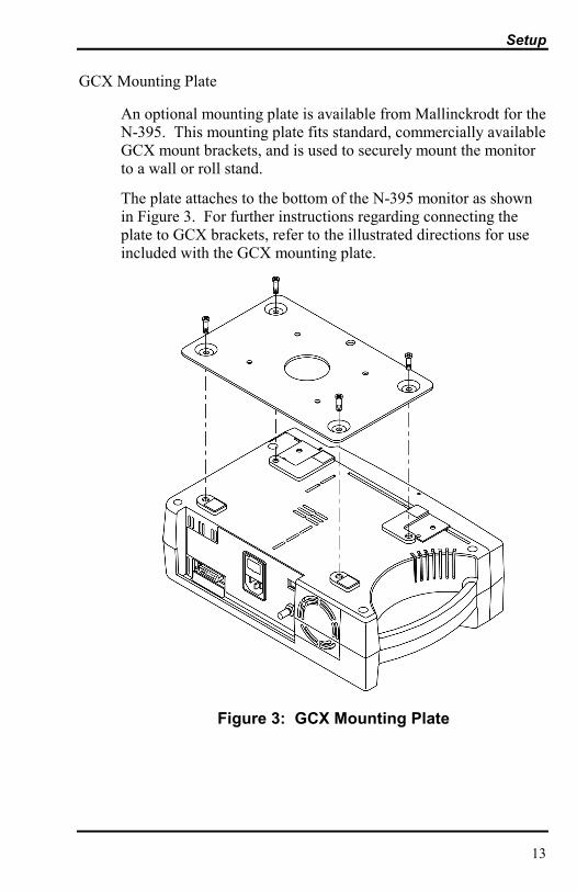
GCX Mounting Plate
An optional mounting plate is available from Mallinckrodt for theN-395. This mounting plate fits standard, commercially availableGCX mount brackets, and is used to securely mount the monitorto a wall or roll stand.
The plate attaches to the bottom of the N-395 monitor as shownin Figure 3. For further instructions regarding connecting theplate to GCX brackets, refer to the illustrated directions for useincluded with the GCX mounting plate.
Figure 3: GCX Mounting Plate
Setup
14
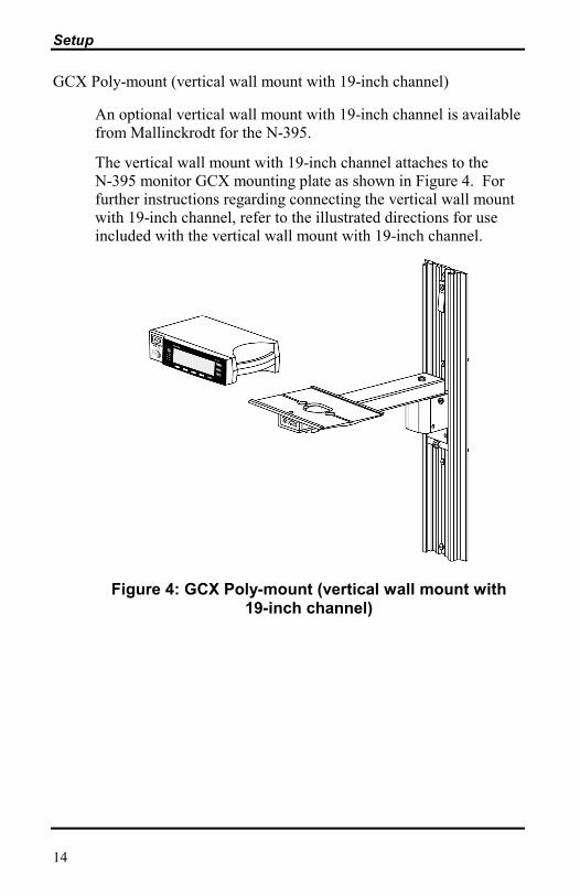
GCX Poly-mount (vertical wall mount with 19-inch channel)
An optional vertical wall mount with 19-inch channel is availablefrom Mallinckrodt for the N-395.
The vertical wall mount with 19-inch channel attaches to theN-395 monitor GCX mounting plate as shown in Figure 4. Forfurther instructions regarding connecting the vertical wall mountwith 19-inch channel, refer to the illustrated directions for useincluded with the vertical wall mount with 19-inch channel.
Figure 4: GCX Poly-mount (vertical wall mount with19-inch channel)

Setup
15
GCX Poly-mount (horizontal wall mount with rail adapter)
An optional horizontal wall mount with rail adapter is availablefrom Mallinckrodt for the N-395.
The horizontal wall mount with rail adapter attaches to the N-395monitor GCX mounting plate as shown in Figure 5. For furtherinstructions regarding connecting the horizontal wall mount withrail adapter, refer to the illustrated directions for use includedwith horizontal wall mount with rail adapter.
Figure 5: GCX Poly-mount (horizontal wall mount withrail adapter)

Setup
16
GCX Roll Stand Poly-mount
An optional GCX roll stand poly-mount is available fromMallinckrodt for the N-395.
The GCX roll stand poly-mount attaches to the N-395 monitorGCX mounting plate as shown in Figure 6. For furtherinstructions regarding connecting the GCX roll stand poly-mount,refer to the illustrated directions for use included with GCX rollstand poly-mount.
Figure 6: GCX Roll Stand Poly-mount

Setup
17
GCX Utility Basket
An optional GCX utility basket is available from Mallinckrodtfor the N-395.
The GCX utility basket attaches to the GCX roll stand poly-mount as shown in Figure 7. For further instructions regardingconnecting the GCX utility basket, refer to the illustrateddirections for use included with GCX utility basket.
Figure 7: GCX Utility Basket

Setup
18
Soft-Sided Carrying Case
An optional soft-sided carrying case is available fromMallinckrodt for the N-395. See Figure 8. The padded carryingcase protects the N-395 while transporting the monitor. Thecarrying case contains two pockets for sensors, cables, andoperator�s manual.
Figure 8: Soft Sided Carrying Case
MONITOR SETUP
General Warnings
WARNING: To ensure patient safety, do not place themonitor in any position that might cause it to fall on thepatient.
WARNING: As with all medical equipment, carefully routepatient cabling to reduce the possibility of patiententanglement or strangulation.

Setup
19
WARNING: Disconnect the N-395 and Nellcor sensor fromthe patient during magnetic resonance imaging (MRI)scanning. Induced current could potentially cause burns.The N-395 may affect the MRI image and the MRI unit mayaffect the accuracy of oximeter measurements.
WARNING: To ensure accurate performance and preventdevice failure, do not subject the N-395 to extreme moisture,such as direct exposure to rain. Such exposure may causeinaccurate performance or device failure.
WARNING: Do not use an N-395 monitor, sensor, cables, orconnectors that appear to be damaged.
WARNING: The N-395 is not defibrillator-proof. However,it may remain attached to the patient during defibrillation orwhile an electrosurgical unit is in use, but the readings maybe inaccurate during use and shortly thereafter.
Connecting the N-395 to AC Power
The N-395 operates on AC power when the hospital-grade powercord is connected to both the monitor and an AC power source(wall outlet).
The supply voltage selector switch allows connection of themonitor to AC power ranging from 100 volts AC to 240 voltsAC. The switch has two positions: one for 100 - 120 volts AC(�115�), and one for 200 - 240 volts AC (�230�). Ensure that thesupply voltage selector switch on the rear panel is set to theproper voltage.
Operating on a Discharged Battery
The N-395 will not operate when its internal battery iscompletely discharged, even when the monitor is connected toAC power. Instead, the error code �EEE 04� will be displayed.This feature prevents the accidental use of the monitor with adead battery. The monitor is only capable of indicating a loss ofAC power if its internal battery is functional.

Setup
20
The battery may discharge during prolonged storage or shipment.If the monitor has been in storage for more than 2 months, it isimportant to plug the monitor into an AC outlet and allow thebattery to charge for approximately 30 minutes before attemptingto operate the instrument on AC power.
To charge a low battery, connect the monitor to AC power. Afull charge of a completely discharged battery takes 14 hourswhile the monitor is turned off.
1. Place the N-395 on a flat surface near the patient. With theoptional wall mount plate available from Mallinckrodt, themonitor may be attached to a GCX Poly-mount bracket.
2. Plug the female connector end of the power cord into the rearof the monitor. Use only the hospital-grade power cordprovided by Mallinckrodt.
3. Plug the male connector end of the power cord into aproperly grounded AC outlet.
4. Verify that the AC Power Indicator is lit. If it is not, ensurethat the supply voltage selector switch matches your ACvoltage source. If the indicator still does not light, contactqualified service personnel, your local Mallinckrodtrepresentative, or the Mallinckrodt Technical ServicesDepartment.
WARNING: In the USA, do not connect the monitor to anelectrical outlet controlled by a wall switch because themonitor may be accidentally turned off.
5. Select a Nellcor sensor appropriate for the patient to bemonitored (see the Sensors and Accessories section of thismanual for sensor selection information).

Setup
21
WARNING: Do not use a sensor cable with theN-395 monitor (other than the SCP-10 or MC-10 sensorcable). Use of another sensor cable will have an adverseeffect on performance. Do not attach any cable that isintended for computer use to the sensor port. Do not connectany device other than a Nellcor approved sensor to the sensorconnector.
6. Plug the sensor into the SCP-10 or MC-10 sensor cable, andsecure the sensor in place by lowering the plastic sensor lockover the sensor connector until it clicks into place (refer tothe SCP-10 or MC-10 directions for use).
7. Plug the SCP-10 or MC-10 cable into the sensor port locatedon the front of the N-395.
LANGUAGE SELECTION
The languages available for display on the screen are English,French, German, Dutch, Portuguese, Spanish, and Italian. TheN-395 is shipped with the factory default English languagedisplayed.
To select the appropriate language after the unit is powered on:
• press the SETUP softkey• press the NEXT softkey• press the LANG softkey• Use the ADJUST UP and ADJUST DOWN Buttons to
select the desired language• Press the EXIT button to return to the main menu.
Service personnel may set the appropriate language as the power-on default using the procedure described in the N-395 servicemanual.

[This page intentionally left blank]

23
SENSORSSelecting a SensorBiocompatibility TestingPerformance Considerations
SELECTING A SENSOR
WARNING: Before use, carefully read the sensor directionsfor use, including all warnings, cautions, and instructions.
WARNING: Do not use a damaged sensor or sensor cable.Do not use a sensor with exposed optical components.
WARNING: Use only Nellcor sensors and sensor cables withthis monitor. Other sensors or sensor cables may causeimproper N-395 performance.
WARNING: Do not use a sensor cable with theN-395 monitor (other than the SCP-10 or MC-10 sensorcable). Use of another sensor cable will have an adverseeffect on performance. Do not attach any cable that isintended for computer use to the sensor port. Do not connectany device other than a Nellcor-approved sensor to the sensorconnector.
WARNING: Tissue damage can be caused by incorrectapplication or duration of use of a SpO2 sensor. Inspect thesensor site periodically as directed in the sensor directions foruse.
When selecting a sensor, consider the patient�s weight andactivity level, the adequacy of perfusion, the available sensorsites, the need for sterility, and the anticipated duration ofmonitoring. For more information, refer to Table 1 or contactyour local Mallinckrodt representative.

Sensors
24
Table 1: Nellcor Sensors
Sensor Model PatientSize
Oxisensor� II oxygen transducers (Sterile,single-use only)
N-25/N-25LFI-20D-20D-25/D-25LR-15
<3 or >40 kg3 to 20 kg10 to 50 kg>30 kg>50 kg
Oxiband� oxygen transducer (Reusable withdisposable nonsterile adhesive)
OXI-A/NOXI-P/I
<3 or >40 kg3 to 40 kg
Oxi 1-2-3 oxygen sensor (Multiuse,nonsterile)
Ox123-A/NOx123-P/I
<3 or >40 kg3 to 40 kg
Durasensor� oxygen transducer (Reusable,nonsterile)
DS-100A >40 kg
Nellcor reflectance oxygen transducer(reusable, nonsterile)
RS-10 >40 kg
Dura-Y� multisite oxygen transducer(Reusable, nonsterile)For use with the Dura-Y sensor:
D-YS >1 kg
Ear clip (Reusable, nonsterile) D-YSE >30 kg
Pedi-Check pediatric spot-checkclip (Reusable, nonsterile)
D-YSPD 3 to 40 kg
OxiCliq� oxygen transducers (Sterile, single-use only)
PNIA
10 to 50 kg<3 or >40 kg3 to 20 kg>30 kg
BIOCOMPATIBILITY TESTING
Biocompatibility testing has been conducted on Nellcor sensorsin compliance with ISO 10993-1, Biological Evaluation ofMedical Devices, Part 1: Evaluation and Testing. The sensorshave passed the recommended biocompatibility testing and aretherefore in compliance with ISO 10993-1.
Sensors
25
PERFORMANCE CONSIDERATIONS
WARNING: Pulse oximetry readings and pulse signal can beaffected by certain ambient environmental conditions, sensorapplication errors, and certain patient conditions.
Inaccurate measurements can be caused by:
• incorrect application of the sensor• placement of the sensor on an extremity with a blood
pressure cuff, arterial catheter, or intravascular line• ambient light• prolonged patient movement
Loss-of-pulse signal can occur for the following reasons:
• the sensor is too tight• a blood pressure cuff is inflated on the same extremity as
the one with the sensor attached• there is arterial occlusion proximal to the sensor
Use only Nellcor sensors and sensor cables.
Select an appropriate sensor, apply it as directed, and observe allwarnings and cautions presented in the directions for useaccompanying the sensor. Clean and remove any substancessuch as nail polish from the application site. Periodically checkto ensure that the sensor remains properly positioned on thepatient.
WARNING: Tissue damage can be caused by incorrectapplication or duration of use of an SpO2 sensor. Inspect thesensor site as directed in the sensor directions for use.
High ambient light sources such as surgical lights (especiallythose with a xenon light source), bilirubin lamps, fluorescentlights, infrared heating lamps, and direct sunlight can interferewith the performance of an SpO2 sensor. To prevent interferencefrom ambient light, ensure that the sensor is properly applied, andcover the sensor site with opaque material.

Sensors
26
Note: Failure to take this precaution in high ambient lightconditions may result in inaccurate measurements.
If patient movement presents a problem, try one or more of thefollowing remedies to correct the problem.
• verify that the sensor is properly and securely applied
• move the sensor to a less active site
• use an adhesive sensor that tolerates some patient motion
• use a new sensor with fresh adhesive backing
If poor perfusion affects performance, consider using theOxisensor R-15 sensor; it obtains measurements from the nasalseptal anterior ethmoid artery, an artery supplied by the internalcarotid. This sensor may obtain measurements when peripheralperfusion is relatively poor.
For low peripheral perfusion, consider using the Nellcor RS-10sensor, which is applied to the forehead or temple. These aresites that may be spared during peripheral vasoconstriction.
Note: The preceding section pertains to patient andenvironmental conditions that can be addressed by sensorselection and application. For information regarding theimpact of other patient environmental conditions onoximeter performance, see "Performance Considerations"in the Start-Up and Use section of this manual.

27
START-UP AND USEBasic OperationAlarmsAdjustable SettingsMenuLimitsTrendSetupBattery OperationDisposal of Device ComponentsPerformance Considerations
BASIC OPERATION
WARNING: The N-395 is a prescription device and is to beoperated by qualified personnel only.
WARNING: Do not lift the monitor by the sensor cable orpower cord because the cable or cord could disconnect fromthe monitor, causing the monitor to drop on the patient.
WARNING: The N-395 is intended only as an adjunct inpatient assessment. It must be used in conjunction withclinical signs and symptoms.
WARNING: Pulse oximetry readings and pulse signal canbe affected by certain ambient environmental conditions,sensor application errors, and certain patient conditions.See the appropriate sections of the manual for specific safetyinformation.
WARNING: Do not silence the audible alarm or decreaseits volume if patient safety could be compromised.

Start-Up and Use
28
WARNING: Each time the monitor is used, check alarmlimits to ensure that they are appropriate for the patientbeing monitored.
Important! Prior to using the N-395, carefully read this manual,accessory directions for use, all precautionary information inboldface type, and all specifications.
Before using the N-395 in a clinical setting, verify that themonitor is working properly and is safe to use. Proper workingcondition can be verified by successful completion of the power-on self-test described in the following steps, and by followinginstructions contained in the �Monitoring Mode� paragraph ofthis section.
Ensure that the supply voltage selector switch on the rear panelmatches the AC voltage at your location.
Power-On Self-Test (POST)
WARNING: Ensure that the speaker is clear of anyobstruction. Failure to do so could result in an inaudiblealarm tone.
1. Plug an appropriate Nellcor sensor firmly into the SCP-10or MC-10 cable and lower the SCP-10 or MC-10 sensorlock over the sensor connector until it clicks into place.Insert the SCP-10 or MC-10 into the N-395 sensor port.Apply the sensor to the patient as described in the sensordirections for use.
2. Turn on the N-395 by pressing the POWER ON/OFFButton. The monitor automatically starts a power-on self-test (POST), which tests its circuitry.

Start-Up and Use
29
3. During the POST, the entire display lights and then theNellcor brand with model number and software version aredisplayed for approximately 3 seconds. All indicator lightsilluminate briefly.
Caution: If any indicator or display element does not light,do not use the monitor. Instead, contact qualified servicepersonnel, your local Mallinckrodt representative, or theMallinckrodt Technical Services Department.
4. If the N-395 detects an internal problem during POST, anerror code or error message may be displayed and a lowpriority alarm will sound. Depending on the reason for thefailure, the screen may be blank or the low priority alarmmay not sound. Refer to the Troubleshooting section for alist of correctable error messages.
5. Upon successful completion of the POST, the N-395 soundsa 1-second tone indicating that the monitor has passed thetest.
WARNING: If you do not hear the POST pass tone, do notuse the monitor.
6. If a sensor is connected to the monitor and the patient, thePulse Search Indicator lights and the N-395 displays zeroesin the %SpO2 and Pulse Rate Displays while it searches fora valid pulse. If a sensor is not attached to the monitor,dashes are displayed and the Pulse Search Indicator is notlit.
When a valid pulse is detected, the N-395 enters theMonitoring Mode and a display similar to the one indicatedin either Figure 9 or Figure 10 is displayed.

Start-Up and Use
30
Figure 9: Monitoring Mode Display - Pleth View
Figure 10: Monitoring Mode Display � Blip(Magnified) View
Adult-Pediatric and Neonatal Settings
WARNING: Each time the monitor is used, check alarmlimits to ensure that they are appropriate for the patientbeing monitored.
Before monitoring, ensure that the N-395 is in the patient setting(adult-pediatric or neonatal) appropriate for the patient beingmonitored. The default power-on setting from the factory is foradult and pediatric patients. To determine which patient settingthe N-395 is in, press the LIMITS softkey. If the monitor is inthe adult-pediatric setting, the Adult Limits screen appears in thedisplay.
To change the N-395 from the adult-pediatric setting to theneonatal setting, press the NEO softkey. To change back toadult-pediatric, press the ADULT softkey.

Start-Up and Use
31
Note: The default power-on operating mode can be changed tothe neonatal patient setting by qualified servicepersonnel using the configuration mode described in theN-395 service manual.
When the patient setting (adult-pediatric or neonatal) ischanged, alarm limits return to power-on defaults for therespective settings and previous patient data is cleared from thedisplay. In the neonate mode, there are different default settingsused. Refer to Default Settings, page 58.
Contrast
To adjust the screen contrast, press and hold the CONTRASTButton on the front panel of the monitor. Press the ADJUST UPor ADJUST DOWN Button to increase or decrease the contrast.Continue to press and hold the buttons to adjust the contrast at afaster rate.
Monitoring Mode
In Monitoring Mode - Pleth View (Figure 9), the N-395 displays%SpO2 readings, pulse rate readings, and a pleth waveform. Inthe Monitoring Mode - Blip (Magnified) View (Figure 10), thePulse Amplitude Indicator and a larger %SpO2 and pulse ratereading are displayed. The pleth waveform is not displayed.Instructions on how to select one of the two views by using thesoftkeys are given later in this section.
The %SpO2 is displayed for values between 1% and 100%.Pulse rates are displayed for values from 20 to 250 beats perminute and zero beats per minute. Pulse rates below 20 (exceptzero) will be displayed as 20, and pulse rates above 250 will bedisplayed as 250. A pulse rate of zero is used to indicate thatthe monitor is not monitoring a pulse.
A variable-pitch beep sounds once for each pulse, and the PulseAmplitude Indicator (in the Blip [magnified] View) visuallydisplays relative pulse strength at the sensor site. The pitch ofthe beep decreases as %SpO2 decreases.

Start-Up and Use
32
Note: Verify that indicators, display information, and audiblesounds including alarms are operational, indicating thatthe monitor is functioning. Each valid button pressshould generate an appropriate audible or visual action.Observe movement of the Pulse Amplitude Indicator orpleth waveform, and listen for pulse beeps to verify thatmeasurements are being made.
Note: If any action does not seem appropriate, do not use themonitor. Instead, contact Mallinckrodt TechnicalServices Department or your local Mallinckrodtrepresentative.
In Monitoring Mode, if the acquired pulse is lost, the monitorenters Pulse Search Mode.
Pulse Search
If the acquired pulse is lost during monitoring, the N-395 entersPulse Search. During Pulse Search, the monitor attempts todetect a pulse from which to take a measurement.
At Initial Power-Up (Sensor Attached to Monitor)
Immediately after POST is completed and the N-395 displays itssoftware version number, the monitor enters Pulse Search Modeand the Pulse Search Indicator lights. If an attached sensor isnot connected to a patient, the display reads zeroes and themonitor remains in the Pulse Search Mode for about 5 seconds.After 5 seconds the pulse search is turned off and SpO2 andPulse Rate display �--- & --- � (dashes and dashes). If the sensoris connected to the patient, the N-395 enters the MonitoringMode when a pulse is detected.
At Initial Power-Up (No Sensor Attached to Monitor)
Immediately after POST is completed and the N-395 displays itssoftware version number, the monitor displays dashes. It doesnot enter the Pulse Search Mode.

Start-Up and Use
33
After Taking Measurements
If a pulse was previously acquired and then lost, the N-395enters Pulse Search, and the Pulse Search indicator lights. Thelast detected readings are displayed while the monitor searchesfor a valid pulse. When the monitor considers the pulse �lost,�it displays zeroes and a high priority alarm sounds.
When a valid pulse is detected, the N-395 exits the Pulse SearchMode and displays the current readings. The Pulse Searchindicator goes out.
Sensor Disconnected
If the sensor cable becomes disconnected from the sensor or themonitor during monitoring, a low priority alarm sounds, valuesfor SpO2 and pulse rate are replaced with dashes, and SENSORDISCONNECTED is displayed on the screen.
Sensor Off
If the sensor becomes disconnected from the patient duringmonitoring, a low priority alarm sounds, values for SpO2 andpulse rate are replaced with dashes, and SENSOR OFF isdisplayed on the screen.
Automatic Shutdown
When all of the following conditions are present for 15 minutes,the N-395 will automatically shut down:
• Running on battery power• No buttons have been pressed• No pulse has been detected (for example, when no patient
is connected to the sensor or the sensor is disconnected)• No alarms are present (other than low battery or a non-
correctable error)

Start-Up and Use
34
ALARMS
The following paragraphs describe the three levels of audioalarms and discuss the management of the loss-of-pulse alarm.
Description of Alarms
The N-395 has three levels of audible alarms.
1. High-priority alarm: Indicated by a fast-rate, high-pitched,pulsing tone. A high-priority alarm sounds after loss-of-pulse is detected.
During a high-priority alarm, the display flashes with thepatient parameter that violated the limit.
2. Medium-priority alarm: Indicated by a medium-rate,medium-pitched, pulsing tone. A medium-priority alarmsounds when any measured patient parameter moves outsidethe set alarm limits, and, if enabled, the SatSeconds limithas been exceeded.
During a medium-priority alarm, the display flashes with thepatient parameter that violated the limit (%SpO2 or PulseRate). If the alarm is a SatSeconds alarm, the SatSecondsindicator will be full.
3. Low-priority alarm: Indicated by a slow, low-pitched,pulsing tone. A low-priority alarm sounds during thefollowing conditions:
• low battery (while operating on battery power)• when an SpO2 cable or sensor has been disconnected
from the monitor or a patient• monitor failure
When operating on DC power, during a low battery condition,the Low Battery Indicator illuminates and the alarm tone soundsimmediately, even if the alarms are silenced or set to OFF.

Start-Up and Use
35
SatSeconds Alarm Management
With traditional alarm management, upper and lower alarmlimits are set for monitoring oxygen saturation. Duringmonitoring, as soon as an alarm limit is violated by as little asone percentage point, an audible alarm immediately sounds.When the %SpO2 level fluctuates near an alarm limit, the alarmsounds each time the limit is violated. Such frequent alarms canbe distracting.
The N-395 utilizes Nellcor SatSeconds alarm managementtechnique. With the SatSeconds technique, upper and loweralarm limits are set in the same way as traditional alarmmanagement. The clinician also sets a SatSeconds limit thatallows monitoring of %SpO2 below the selected low alarm limitfor a period of time before an audible alarm sounds.
The SatSeconds limit controls the time that the %SpO2 levelmay fall below the alarm limit before an audible alarm sounds.
The method of calculation is as follows:
The number of percentage points that the %SpO2 falls outsidethe alarm limit is multiplied by the number of seconds that the%SpO2 level remains outside that limit. This can be stated as anequation:
Points x Seconds = SatSeconds
Where:
Points = SpO2 percentage points below of the limit
Seconds = number of seconds SpO2 remains atthat point below of the limit
For example, Figure 11 demonstrates the alarm response timeassuming a SatSeconds limit set at 50, and a lower alarm limitset at 90 percent.
In this example, the %SpO2 level drops to 88 (2 points) andremains there for a period of 2 seconds (2 points x 2 seconds =4). The %SpO2 then drops to 86 for 3 seconds and then to 84for 6 seconds. The resulting SatSeconds are:

Start-Up and Use
36
%SpO2 Seconds SatSeconds2 x 2 = 44 x 3 = 126 x 6 = 36
Total SatSeconds = 52
After approximately 10.9 seconds the SatSeconds alarm wouldsound, because 50 SatSeconds had been exceeded. See arrow(�) in Figure 5.
Figure 11: Alarm Response with SatSeconds
Saturation levels may fluctuate rather than remaining steady fora period of several seconds. Often, %SpO2 levels may fluctuateabove and below the alarm limit, re-entering the non-alarmrange several times.

Start-Up and Use
37
During such fluctuation, the N-395 integrates the number of%SpO2 points, both positive and negative, until either theSatSeconds limit (SatSeconds setting) is reached, or the %SpO2level returns within a normal range and remains there.
SatSeconds "Safety Net"
The SatSeconds "Safety Net" is for patients with saturationhaving frequent excursions below the limit, but not stayingbelow the limit long enough for the SatSeconds setting to bereached. When 3 or more limit violations occur in 60 secondsan alarm will sound even if the SatSeconds setting has not beenreached.
Determining the SatSeconds
The SatSeconds setting may be set at 10, 25, 50, or 100SatSeconds, or it may be set to OFF. The factory default settingis �OFF�. The decision to utilize the SatSeconds feature and atwhat limit, or not to use it at all, must be made based on themedical assessment of the patient�s clinical signs and symptoms.
To set the SatSeconds limit:
1. Press the LIMITS softkey.
2. Press the SELECT softkey to move to %SpO2 SECS.
3. When the %SpO2 SECS field is highlighted, use theADJUST UP or ADJUST DOWN button to select thedesired limit. Choices are: 10, 25, 50, or 100 or OFF.
4. After selecting the SatSeconds limit; press the EXITsoftkey to return to the main display.

Start-Up and Use
38
SatSeconds Display
When the N-395 SatSeconds technology detects an SpO2 valueoutside the alarm limit, the SatSeconds indicator begins to �fill�clockwise. When the SpO2 value is within the set limits, theSatSeconds indicator will empty counter-clockwise. As secondspass and are compared against the alarm-limit and theSatSeconds setting, the graph fills or empties proportionately.The SatSeconds circular graph is located on the right side of thedisplay, adjacent to the SpO2 reading in the pleth view and at thefar left of the display in the blip view.
When the graph is completely filled, indicating that the selectedSatSeconds limit has been reached, an audible alarm sounds andthe displayed %SpO2 value flashes. As with traditional alarmmanagement, the audible alarm may be silenced by pressing theALARM SILENCE button.
ADJUSTABLE SETTINGS
The following adjustments can be made using the AdjustUp/Down and ALARM SILENCE Buttons.
• Pulse beep volume• Alarm volume• Alarm silence duration• Disabling audible alarms
Pulse Beep Volume
To adjust the pulse beep volume during normal monitoring,press and hold the ADJUST UP or ADJUST DOWN Button tochange the setting. Pressing and holding the ADJUST DOWNButton will cause the volume to decrease until it is no longerheard.
Start-Up and Use
39
Alarm Volume
To view the current volume of the audible alarm, press and holdthe ALARM SILENCE Button for more than 3 seconds. Thecurrent volume level is indicated in the Pulse Rate Display as avalue from 1 (lowest) to 10 (highest). A tone at the displayedlevel sounds.
To adjust the volume, press and hold the ALARM SILENCEButton until VOL is displayed. Continue pressing the ALARMSILENCE Button and press the ADJUST UP or ADJUSTDOWN Button to change the setting. The volume cannot be setto zero.
Alarm Silence Duration
Alarms can be silenced for a preset period called the audiblealarm silence duration. To view the current setting, press andhold the ALARM SILENCE Button for less than 3 seconds. Toadjust the setting, press and hold the ALARM SILENCE Button(for less than 3 seconds) and use the ADJUST UP or ADJUSTDOWN Buttons to increase or decrease the value. Possiblevalues are 30, 60, 90, or 120 seconds, or OFF. (The OFFselection is discussed later in this section.)
The audible alarm silence duration begins when the ALARMSILENCE Button is pressed.
Subsequently, if any alarm condition (other than a low batteryalarm) occurs while the alarm is silenced, the alarm will notsound until the alarm silence duration period expires. Operatingthe monitor on battery power during a low battery alarmcondition will cause a low battery alarm to sound, even if theduration time has not elapsed.
If the ALARM SILENCE Button is pressed during the alarmsilence duration, the alarm silence duration is ended and theaudible alarms are re-enabled.
Visual indications of an alarm condition cannot be turned off.For example, if the %SpO2 SatSeconds upper alarm limit isexceeded, the alarm can be silenced for the alarm silenceduration, but the %SpO2 value will continue to flash.

Start-Up and Use
40
If the alarm condition is still present when the alarm silenceduration has elapsed, the alarm will sound.
WARNING: Do not silence an audible alarm or decrease itsvolume if patient safety could be compromised.
Disabling Audible Alarms
Setting the alarm silence duration to OFF means that themonitor will produce no audible alarms.
To set the alarm silence duration to OFF, press and hold theALARM SILENCE Button for less than 3 seconds and use theADJUST UP Button to increase the current setting until �OFF�is displayed. The Alarm Silence Indicator flashes, indicatingthat audible alarms have been disabled. To re-enable audiblealarms, the duration must be set to something other than OFF.
Visual indications of an alarm condition are not affected bydisabling the audible alarms.
The ability to set the alarm silence duration to OFF can beenabled or disabled by qualified service personnel as describedin the service manual.
The factory default is that the capability of setting the alarmsilence duration to OFF is enabled.
Alarm Silence Reminder
The factory default is that the reminder is enabled. Servicepersonnel must enable or disable this function as required byeach institution. Refer to the N-395 service manual for theprocedure.

Start-Up and Use
41
MENU
Menu Structure
The four softkeys on the front panel are used to view or adjustthe following N-395 settings or functions:
• %SpO2 and pulse rate alarm limits• Pleth or Blip view• Time and date settings• Data port baud rate settings• Trend data viewed (%SpO2, pulse, or both)• �Zoom� factor of trend data• Graph of trend data (histogram)• Delete all trend data• Print trends• SatSeconds limits• Language displayed on screen or data port• Nurse call settings• Analog output calibration voltage settings• Display backlight on/off
Menu items are selected by pressing and releasing thecorresponding softkey directly below the item. Refer to Table 2:Limits Menu to access menu items.
Note: If, after accessing a submenu, no buttons are pressed for10 seconds, the display will time out and return to themain menu. Exceptions to this are the clock and trendmenus, which will time out in 5 minutes and the analogport calibration menu, which times out in 2 minutes.

Start-Up and Use
42
A description of each menu item is included in the followingparagraphs.
LIMITS
WARNING: Each time the monitor is used, check alarmlimits to ensure that they are appropriate for the patientbeing monitored.
Overview
When the N-395 is first turned on, alarm limits are set to theirpower-on default values. Qualified service personnel, using theinstructions described in the N-395 service manual, may changepower-on default alarm limits.
Alarm limits may be changed from their power-on default valuesif necessary, as described below. Limit changes made willremain in effect until changed again or until the N-395 is turnedoff.
Viewing Current Alarm Limits
To view the current alarm limit values from the main menu,press the LIMITS softkey. The current upper and lower alarmlimits for %SpO2 and pulse rate are displayed. The currentSatSeconds alarm limit is also shown.

Start-Up and Use
43
Changing Alarm Limits
Use the SELECT softkey to select the parameter that is to bechanged. Use the ADJUST UP/DOWN Buttons to change thesettings. The setting takes effect immediately and remains ineffect when the alarm setting menu is exited.
Table 2: Limits Menu

Start-Up and Use
44
Table 3: Trend Menu

Start-Up and Use
45
Table 4: Setup Menu

Start-Up and Use
46
Alarm Limits Changed Indicator
If alarm limits are changed from the N-395�s power-on defaults,a decimal point appears after the displayed value and in the%SpO2 and Pulse Rate Display as illustrated in Figure 12. Thedecimal point remains on the display until the N-395 is turnedoff or the limit is returned to its default value.
Figure 12: Alarm Limits Selection
TREND
The N-395 can graphically display trends for SpO2, pulse rate,or both. Trend data is stored at 4-second intervals. When theTREND softkey is pressed, �READING TRENDS . . ..� isdisplayed at the bottom of the screen, indicating that the monitoris collecting the trend data.
The monitor stores up to 48 hours of trend data. The amount oftrend data displayed on the screen is determined using theZOOM softkey. Settings available are 40 seconds, 15 or 30minutes, and 1, 2, 4, 8, 12, 24, 36, or 48 hours. All data aredisplayed in a graph format except the 40-second setting, whichis shown in tabular format.
When the trends are displayed, the most recent readings are onthe right side of the graph. The graph indicates the highest andlowest parameter values during the period of time representedby the width of the cursor (vertical dotted line).
The highest and lowest values of the parameter at the cursor areindicated on the left side of the screen (�95� and �98� in Figure13). These values are not the current patient readings butrepresent the highest/lowest trend values at the cursor.

Start-Up and Use
47
Figure 13: SpO2 Trend
Periods of time when no measurements were acquired areindicated by blank spaces in the graph as shown in Figure 13.
The number of trend hours or minutes currently displayed on thescreen is indicated in the upper left corner. The date and timeindicate the location of the cursor on the top middle and right ofthe screen.
The cursor is moved right or left by using the ADJUSTUP/DOWN Buttons. Each press of the button causes the cursorto move a certain period of time depending on the trend scale, asindicated in Table 5.
Table 5: Trend Scale
TrendScale
Amount of Time Represented byOne Press of the ADJUST UP/DOWN Button
40 seconds 4 seconds15 minutes 5 seconds30 minutes 10 seconds1 hour 20 seconds2 hours 40 seconds4 hours 1 minute, 20 seconds8 hours 2 minutes, 40 seconds12 hours 4 minutes24 hours 8 minutes36 hours 12 minutes48 hours 16 minutes

Start-Up and Use
48
Scrolling past the limits of the right or left edges of the screencauses the viewing area to shift, relocating the cursor to themiddle of the screen if enough trend data is available.
For example, suppose the time represented by the right-handedge of the screen in Figure 13 is 14:54:05. Scrolling one timeperiod to the right (4 minutes) results in the cursor relocating tothe center of the screen at the time period 14:58:05, with 6 hoursof data on both sides of the cursor. If no data were available tothe right of the screen, an invalid tone would sound. If only 3hours of data was to the right of the screen, the cursor wouldrelocate to approximately 3/4 of the way to the right of thescreen, at the time period 14:58:05.
Note: The screen will return to the monitoring mode if analarm sounds, the ALARM SILENCE Button is pressedor a trend or histogram has been displayed for 5 minuteswith no button presses.
View
Pressing the VIEW softkey allows selection of the followingtrend displays: DUAL, SPO2, PULSE, HIST, or AMP. Toselect HIST or AMP press VIEW, then NEXT.
Dual Trend Display
The dual trend display provides trend information on the %SpO2and pulse rate. See Figure 14.
Figure 14: Dual Trend Display

Start-Up and Use
49
SpO2 Trend Display
The SpO2 trend display provides information on the %SpO2trend. See Figure 15.
Figure 15: SpO2 Trend Display
Pulse Rate Trend Display
The pulse rate trend display provides information on the pulserate trend. See Figure 16.
Figure 16: Pulse Rate Trend Display
Histogram
The histogram view is illustrated in Figure 17.The histogramgraphically illustrates the percentage of time a given range ofvalues has been measured. The period of time covered is givenin the upper left corner of the display. Only points with data areincluded in the histogram.
For example, in Figure 17, the histogram is for the last 12 hours.During those 12 hours, 68% of the %SpO2 measurements werefrom 96 to 100, 7% of the measurements were from 91 to 95,and 25% of the measurements were from 0 to 80.

Start-Up and Use
50
NEXTVIEW EXIT
12HR HISTOGRAM%SPO2 BPM
25JUL 04:02--25JUL 16:02
96-10091-9586-9081-85
0-80
68%7%0%0%
25%
201-250151-200101-150
51-1000-50
0%0%
18%57%25%
Figure 17: Histogram
AMP (Amplitude) Trend Display
The AMP trend display provides trend information on the pulseamplitude. See Figure 18.
Figure 18: AMP Trend Display
Zoom
Pressing the ZOOM softkey changes the period of timedisplayed on a trend graph. Selectable times displayedgraphically in the upper left corner are 48, 36, 24, 12, 8, 4, 2, or1 hours, and 30 or 15 minutes. The location of the cursor, asindicated by the time in the upper right-hand corner of thescreen, remains the same.
A table is used to display 40-second trends.
The ZOOM softkey is not displayed for the histogram trendview.
40-Second Trends Table
The 40-second trends table is available by continuing to pressthe ZOOM softkey. As indicated in Figure 19, the timeindicated on trend graphs by the cursor is displayed in the upperright-hand corner of the screen and is highlighted in the table.Press the DOWN ARROW button to highlight the time of thetrends readings. The readings are in 4-second increments and go

Start-Up and Use
51
back in time as the DOWN ARROW button is pressed andforward in time as the UP ARROW button is pressed.
Figure 19: 40-Second Trends
When the oldest reading on the screen is highlighted and theDOWN ARROW button is pressed again, the screen shifts todisplay an older column of readings. Similarly, if the newestreading on the screen is highlighted and the UP ARROW buttonis pressed, the screen shifts to display a newer column ofreadings.
Next
The NEXT softkey provides access to the DELETE and PRINTsoftkeys.
Delete
Pressing the DELETE softkey presents two options: YES or NO.YES deletes all trend information from the N-395 memory andthe display. NO returns the N-395 to the previous menu.
Note: The protocol setting must be set to ASCII MODE orGRAPH MODE to transmit text or graphical data.Check this setting using the COMM softkey as indicatedin the following paragraphs.
ASCII MODE: Pressing the PRINT softkey begins thetransmission of data via the data port to a connected PC or serialprinter. The output is tabular and all 48 hours of data inmemory will be output.

Start-Up and Use
52
GRAPH MODE: The graph mode disables all printouts exceptfor trend printouts. Pressing the PRINT softkey from the trendmenu will print a graphical printout of the displayed graphicaltrend data. The amount of data printed is the same as the trendbeing displayed. Contact Mallinckrodt�s Technical ServicesDepartment for a list of compatible printers.
Refer to Data Port Protocol of this manual for more informationconcerning the data port.
SETUP
The SETUP softkey allows selection or viewing of the followingsettings:
• view displayed on the screen (PLETH or BLIP)• time and date• data port baud rate and protocol• language displayed on the screen• data port nurse call normally high or normally low setting• data port analog calibration voltage.
Press the SETUP softkey once to display VIEW and CLOCK.Then press NEXT to display COMM and LANG. Press NEXTagain to display NCALL and ANALOG.
VIEW
The VIEW softkey allows selection of the screen to bedisplayed, PLETH or BLIP (magnified). The pleth viewdisplays the pleth waveform. The BLIP view displays the PulseAmplitude Indicator and larger numerical values for easierviewing.
CLOCK
The CLOCK softkey provides a means to set the time and date.
Press the SET softkey to access the SELECT softkey. Use theSELECT softkey to select the item to be changed. Use theADJUST UP/DOWN Buttons to adjust the setting. The date isexpressed as DD-MMM-YY. For example, November 29, 1998,would be expressed as 29 - NOV - 98.

Start-Up and Use
53
Note: The N-395 will time out in 5 minutes when the SET andEXIT softkeys are displayed. However, it will time outin 10 seconds after the SET button is pressed if there areno further button presses.
Press the EXIT button to accept the new settings. Press EXITagain to return to the previous menu.
COMM
Press the NEXT softkey to access the COMM softkey. TheCOMM softkey provides selection of the baud rate and theprotocol of the data port.
After pressing the COMM softkey, use the ADJUST UP/DOWNButtons to select a baud rate of 2400, 9600, or 19200. PressExit to return to the SETUP submenu.
Press the SELECT softkey to highlight the protocol setting. Usethe ADJUST UP/DOWN Buttons to select the desired setting.ASCII is used during normal operation and for serial printers.GRAPH is used for graphical trend printouts when connected toa serial printer. Select OXINET when connecting to an Oxinet�II central station network or Score software. The BedsideMonitor Interface selections are (contained in N-395 softwareversions 1.7 and higher) AGILENT (for Agilent HP monitors),SPACELBS (for SpaceLab monitors), MARQ (for Marquettemonitors), and DATEX (for Datex-Ohmeda AS/3 monitors). Donot use the CLINICAL setting unless instructed to do so byMallinckrodt�s Technical Services personnel. Press Exit toreturn to the SETUP submenu.
Bedside Monitor Interface
The bedside monitor interface (contained in N-395 softwareversions 1.7 and higher) allows the N-395 monitor tocommunicate real-time monitoring information to a �host�bedside monitor. The purpose of bedside monitor interface is toallow integrate Oxismart XL oximetry technology into the hostsystem for remote monitoring, trending, data storage, and otherfeatures offered by the �host� system.

Start-Up and Use
54
Agilent (HP) Communications
The N-395 sends SpO2, pulse rate, and alarm status data to theAgilent monitor.
The Agilent monitor requires an Agilent VueLink Aux Plus Binterface module to interface with the N-395 pulse oximeter.
The RS-232 hardwire interface cable has a DB-15 connector forthe N-395 and the applicable connector for the Agilent monitor.Nellcor cable part number 902256 is recommended for thisinterface.
Note: Spare parts for the N-395 are listed on the Internet,confirm the cable part number before ordering a cable.The Internet address is:http://mallinckrodt.com/respiratory/resp/Serv_Supp/Apartweb/main/PartAcceMenu.html.
A blank screen on the Agilent monitor will indicate corrupt data.The Agilent monitor will detect corrupt data in less than 100milliseconds.
When the N-395 is in the Agilent mode of operation theinterface baud rate must be set to 19,200 bits per second. Pressthe SETUP softkey, then the NEXT softkey, and then theCOMM softkey to select BAUD. Use the ADJUST UP orADJUST DOWN buttons to select the correct baud rate.
WARNING: Do not silence the N-395 audible alarm ordecrease its volume if patient safety could be compromised.
The Agilent monitor only displays visual alarm indications. TheN-395 monitor must be able to sound an audible alarm in orderto maintain patient safety.
SpaceLabs Communications
The N-395 sends SpO2, pulse rate, and alarm status data to theSpaceLabs monitor.
Figure 20 illustrates the connections between the N-395 and theSpaceLabs Monitor.

Start-Up and Use
55
Figure 20: SpaceLabs Connection
Caution: The SpaceLabs monitor must be turned on beforethe N-395 monitor is turned on.
The SpaceLabs monitor requires a Universal FlexPort interface module to interface with the N-395 pulse oximeter.
The RS-232 hardwire interface cable has a DB-15 connector forthe N-395 and the applicable connector for the SpaceLabsFlexPort interface module cable. Nellcor cable part number036341 is recommended for this interface.
Note: Spare parts for the N-395 are listed on the Internet,confirm the cable part number before ordering a cable.The Internet address is:http://mallinckrodt.com/respiratory/resp/Serv_Supp/Apartweb/main/PartAcceMenu.html.
Corrupt data will be indicated by a Communications Errordisplayed on the SpaceLabs monitor. The SpaceLabs monitorwill detect corrupt data in less than 11 seconds.
When the N-395 is in the SpaceLabs mode of operation theinterface baud rate must be set to 9,600 bits per second.Pressing the SETUP softkey, then the NEXT softkey, and thenthe COMM softkey to select BAUD. Use the ADJUST UP orADJUST DOWN buttons to select the correct baud rate.

Start-Up and Use
56
WARNING: Do not silence the N-395 audible alarm ordecrease its volume if patient safety could be compromised.
The SpaceLabs monitor provides both audible and visual alarmindications. Silencing the N-395 alarm will also silence theSpaceLabs monitor alarms. The monitors must be able to soundan audible alarm in order to maintain patient safety.
Marquette Communications
The N-395 sends SpO2, pulse rate, and alarm status data to theMarquette monitor.
The Marquette monitor requires an Octanet interface moduleto interface with the N-395 pulse oximeter. The interfacemodule comes with an interface cable, GE Marquette partnumber 417961-033, that connects to the Nellcor interfacecable.
The RS-232 hardwire interface cable has a DB-15 connector forthe N-395 and the applicable connector for the MarquetteOctanet interface module cable. Nellcor cable part number902254 is recommended for this interface.
Note: Spare parts for the N-395 are listed on the Internet,confirm the cable part number before ordering a cable.The Internet address is:http://mallinckrodt.com/respiratory/resp/Serv_Supp/Apartweb/main/PartAcceMenu.html.
Corrupt data will be indicated by a Communications Errordisplayed on the Marquette monitor. The Marquette monitorwill detect corrupt data in less than 7 seconds.
When the N-395 is in the Marquette mode of operation theinterface baud rate must be set to 9,600 bits per second.Pressing the SETUP softkey, then the NEXT softkey, and thenthe COMM softkey to select BAUD. Use the ADJUST UP orADJUST DOWN buttons to select the correct baud rate.
The GE Marquette monitor only sounds audible alarms.Silencing the N-395 audible alarm has no effect on the GEMarquette monitor sounding an alarm.

Start-Up and Use
57
Datex-Ohmeda Communications
The Datex-Ohmeda monitor AS/3 must be configured forcommunications with the Nellcor N-200 monitor in order tocommunicate with the N-395 monitor. Refer to the AS/3operator�s manual for instructions on configuring the AS/3monitor.
The N-395 sends SpO2, pulse rate, and alarm status data to theDatex AS/3 monitor.
The RS-232 hardwire interface cable has a DB-15 connector forthe N-395 and the applicable connector for the Datex monitor.Nellcor cable part number 902255 is recommended for thisinterface.
Note: Spare parts for the N-395 are listed on the Internet,confirm the cable part number before ordering a cable.The Internet address is:http://mallinckrodt.com/respiratory/resp/Serv_Supp/Apartweb/main/PartAcceMenu.html.
Corrupt data will be indicated by a Communications Errordisplayed on the Datex monitor. The Datex monitor will detectcorrupt data in less than 11 seconds.
When the N-395 is in the Datex mode of operation the interfacebaud rate must be set to 2,400 bits per second. Pressing theSETUP softkey, then the NEXT softkey, and then the COMMsoftkey to select BAUD. Use the ADJUST UP or ADJUSTDOWN buttons to select the correct baud rate.
WARNING: Do not silence the N-395 audible alarm ordecrease its volume if patient safety could be compromised.
The Datex-Ohmeda monitor does not indicate audible or visualalarms. The N-395 monitor must be able to sound an audiblealarm in order to maintain patient safety.
LANG
The LANG softkey provides selection of the language displayedon the screen.

Start-Up and Use
58
Press the NEXT softkey to access the LANG softkey. Afterpressing the LANG softkey, use the ADJUST UP/DOWNButtons to select English, French, German, Italian, Spanish,Dutch, or Portuguese.
If the language is changed and EXIT is pressed (or a 10-secondtimeout occurs), the monitor begins displaying data in theselected language.
NCALL
The NCALL softkey provides the capability of setting the alarmvoltage at a normally high (NORM +) or normally low(NORM -). Refer to the �Nurse Call� heading of Data PortProtocol for a more thorough explanation of these settings. Thenurse call feature is also discussed later in this section.
ANALOG
The ANALOG softkey provides the capability to producevariable calibrating voltages to calibrate instruments such as achart recorder. Refer to the �Analog Outputs� heading of DataPort Protocol for a more thorough explanation of these settings.
LIGHT
The LIGHT softkey turns the backlight on or off. When thebacklight is off, pressing any softkey turns the backlight on.Also, the CONTRAST and ALARM SILENCE keys will turnthe backlight on. Any alarm will turn the backlight on. Turningthe backlight off conserves battery power.
Default Settings
The N-395 is shipped with factory default settings (Table 6 andTable 7). Authorized technical personnel using the proceduresdescribed in the N-395 service manual can change defaultsettings.
Note: Factory default settings are constants that cannot bechanged without re-compiling software.

Start-Up and Use
59
Table 6: Factory Default Settings (Adult)
Monitoring Mode Adult
%SpO2 Lower Alarm Limit: 85%%SpO2 Upper Alarm Limit: 100%Alarm Silence Duration OFFSetting:
Enabled
Alarm Silence Duration: 60 secondsAlarm Silence Reminder: EnabledAlarm Volume: 75 dB(A) peak at 1 meter
(volume setting of 5)Data Port Baud Rate: 9600Data Port Protocol: ASCIIDisplay Contrast: MidrangeDisplay Format: PlethLanguage: EnglishNurse Call Polarity: Normally LowPulse Beep Volume: 72 dB(A) at 1 meter
(volume setting of 4)Pulse Rate Lower Alarm Limit: 40 beats per minutePulse Rate Upper Alarm Limit: 170 beats per minuteSatSeconds OffTrend Display: %SpO2

Start-Up and Use
60
Table 7: Factory Default Settings (Neonate)
Monitoring Mode Neonate
Note: There are different default settings for the neonate mode.%SpO2 Lower Alarm Limit: 80%%SpO2 Upper Alarm Limit: 95%Pulse Rate Lower Alarm Limit: 90 beats per minutePulse Rate Upper Alarm Limit: 190 beats per minuteSatSeconds: Off
Nurse Call Feature
WARNING: The nurse call feature should not be used asthe primary source of alarm notification. The audible andvisual alarms of the monitor, used in conjunction withclinical signs and symptoms, are the primary sources fornotifying medical personnel that an alarm condition exists.
The nurse call feature of the N-395 works in conjunction withthe nurse call system of the institution when the monitor soundsan audible alarm. It is accessed through the data port (pins 7, 8,10, 11, or 15, as indicated in Table 10).
WARNING: The nurse call feature is not functionalwhenever the monitor alarms are silenced.
The nurse call feature is available when the N-395 is operatedon AC power or its internal battery, and the monitor has beenelectronically connected to the hospital�s nurse call system.Qualified service personnel may refer to the N-395 servicemanual for complete connection instructions.
Prior to using the monitor in a clinical setting, test the nurse callfeature by creating an alarm condition, then verifying that thehospital�s nurse call system is activated.

Start-Up and Use
61
BATTERY OPERATION
The N-395 has an internal battery that may be used to power themonitor during transport or when AC power is not available. Anew, fully charged battery will provide at least 2 hours ofmonitoring time under the following conditions: no audiblealarms sound, and no analog or serial output devices areattached.
Note: Whenever the monitor is connected to AC power, thebattery is being charged. Therefore, it is recommendedthat the monitor remain connected to AC power whennot in use. This will make available a fully chargedbattery for use at any time.
The monitor cannot operate with a fully discharged battery.Before attempting to turn on an N-395 whose battery charge hasbeen depleted, first plug the monitor into an AC outlet to allowthe battery to charge for a few minutes. The monitor may thenbe powered on.
To charge a dead battery, connect the monitor to AC power. Afull charge takes 14 hours while the monitor is turned off.
When all of the following conditions are present for 15 minutes,the N-395 will automatically shut down:
• Monitor is running on battery power• No buttons have been pressed• No pulse has been detected (for example, when no patient
is connected to the sensor or the sensor is disconnected)• No alarms are present (other than low battery or a non-
correctable error)
Low Battery Indicator
The Low Battery Indicator lights and a low priority alarm beginsto sound when approximately 15 minutes of monitoring time isavailable on the existing battery charge. This alarm cannot besilenced while operating on battery power.

Start-Up and Use
62
Note: If the AC voltage selector switch on the rear panel doesnot match the AC voltage source, the monitor may runon battery power, even though it is plugged in, whichwill eventually result in a low priority alarm and alighted low battery indicator. Ensure that the switchsetting matches the AC voltage.
If the monitor is not connected to AC power withinapproximately 15 minutes, it will shut down.
Note: As the battery is used and recharged over a period oftime, the amount of time between the onset of the lowbattery alarm and the instrument shut-off may becomeshorter.
If the backlight is turned off during a low battery condition, itcannot be turned back on.
It is recommended that qualified service personnel replace theinternal battery every 24 months.
Caution: If the N-395 is to be stored for a period of 3months or longer, notify service personnel to remove thebattery from the monitor prior to storage. Recharge thebattery when it has not been charged for 2 or more months.
DISPOSAL OF DEVICE COMPONENTS
Caution: Follow local governing ordinances and recyclinginstructions regarding disposal or recycling of devicecomponents, including batteries.
PERFORMANCE CONSIDERATIONS
Impact of Patient Conditions on Monitor Readings
Certain patient conditions can affect the measurements of theN-395 and cause the loss of the pulse signal.
WARNING: Pulse oximetry readings and pulse signals canbe affected by certain ambient environmental conditions,sensor application errors, and certain patient conditions.

Start-Up and Use
63
Inaccurate measurements can be caused by:
• prolonged patient movement• venous pulsations• intravascular dyes, such as indocyanine green or
methylene blue• significant levels of dysfunctional hemoglobins• defibrillation
Ambient environmental conditions and sensor applicationerrors, which can affect pulse oximetry readings, are discussedin the Sensors and Accessories section of this manual and in thesensor directions for use.
The effects of electromagnetic interference on oximetryreadings are discussed in the Troubleshooting and Maintenancesection of this manual.

[This page intentionally left blank]
65
TROUBLESHOOTING AND MAINTENANCETroubleshootingEMI (Electromagnetic Interference)Obtaining Technical AssistanceReturning the N-395Maintenance
TROUBLESHOOTING
WARNING: If you are uncertain about the accuracy of anymeasurement, check the patient�s vital signs by alternatemeans; then make sure the monitor is functioning correctly.
WARNING: The cover should be removed only by qualifiedservice personnel. There are no user-serviceable parts inside.
Error Codes
When the N-395 detects an error condition, it may display theletters �EEE� followed by an error code.
When an error code (other than the ones listed in Table 8) isdisplayed, turn the instrument off and back on again. If the errorcode reappears, record it and notify service personnel.
Error messages will be displayed along with the error codes listedin Table 8. If the error codes are encountered, perform theprescribed action as indicated in the table.

Troubleshooting and Maintenance
66
Table 8: Error Codes and Messages
ErrorCode
ErrorMessage
Action
4 LOWBATTERY
The battery is discharged to a critically low level.Check to ensure that the voltage selector switch on therear panel is set to the proper voltage.Turn the monitor off and let it charge forapproximately 10 minutes and then reattempt to turnthe unit on. If the error code is still present, turn theunit off and let it continue to charge. If the monitorhas been charged for 30 minutes and the error code isstill present, notify service personnel.
80 DEFAULTSLOST
The current power-on default settings have been lostand returned to factory defaults. Qualified servicepersonnel can use the service manual to restore thedesired power-on default settings.
81 SETTINGSLOST
The current settings (for example, alarm limits, alarmand pulse beep volumes, alarm silence duration) havebeen lost and returned to power-on defaults. Turn themonitor off and back on again. If it is necessary tohave settings different from the power-on defaultsettings, turn the monitor off and back on again, andreenter the desired settings.
82 CLOCKSETTINGLOST
The date and time settings have been lost. Re-enter thedate and time.
Other Messages
In addition to the messages listed in Table 8, the followingmessages may be encountered:
SENSOR DISCONNECTED - The sensor has disconnected fromthe cable, the cable has disconnected from the monitor, or thesensor/cable wiring is defective. Press the ALARM SILENCEButton to silence the alarm. Check the connections. If this doesnot correct the problem, replace the sensor and/or cable.

Troubleshooting and Maintenance
67
SENSOR OFF - The sensor has become disconnected from thepatient. Press the ALARM SILENCE Button to silence thealarm. Check the sensor to patient connection. If this does notcorrect the problem, replace the sensor.
DISALLOWED ON BATTERY - An attempt to print ordownload data port information while operating on battery powerhas been made. Connect to AC power and retry.
DISALLOWED ON LOW BATTERY - An attempt to turn onthe backlight has been made while in a low battery condition. Ifthe backlight is turned off during a low battery condition, itcannot be turned back on.
READING TRENDS - The monitor is gathering trendinformation for display.
INVALID SILENCE DURATION - An attempt has been made toset the alarm silence duration power-on default to �OFF.� Thepower-on default cannot be set to �OFF.�
INVALID SpO2 LIMIT - An attempt has been made to set eitherthe upper or lower alarm limit power-on default below 80. Thepower-on default cannot be set below 80.
Suggested Corrective Actions
If you experience a problem while using the N-395 and areunable to correct it, contact qualified service personnel or yourlocal Mallinckrodt representative. The N-395 service manual,which is for use by qualified service personnel, providesadditional troubleshooting information.
Following is a list of possible errors and suggestions forcorrecting them.
1. There is no response to the POWER ON/OFF Button.
• If operating on AC power, ensure that the supplyvoltage selector switch is set to the proper voltage.
• If operating on AC power, the fuse may be blown.Notify service personnel to check and, if necessary,replace the fuse.

Troubleshooting and Maintenance
68
• If operating on battery power, the battery may bemissing or discharged. If the battery is discharged,notify service personnel to charge or replace thebattery.
2. One or more display elements or indicators do not lightduring the power-on self-test.
• Do not use the N-395; contact qualified servicepersonnel or your local Mallinckrodt representative.
3. The monitor is operating on battery power, even thoughit is connected to AC.
• Ensure that the supply voltage selector switch is setto the proper voltage.
• Make sure that the power cord is properlyconnected to the N-395.
• Check to see if power is available to otherequipment on the same AC circuit.
4. The Pulse Search Indicator is lit for more than 10seconds (before any measurements are taken).
• Check the sensor directions for use to determine ifan appropriate sensor is being used and if it isapplied properly. Check sensor and sensor cableconnections. Test the sensor on someone else. Tryanother sensor or sensor cable.
• Perfusion may be too low for the N-395 to track thepulse. Check the patient. Test the instrument onsomeone else. Change the sensor site. Try anothertype of sensor.
• Excessive patient motion may be preventing theN-395 from tracking the pulse. Keep the patientstill, if possible. Verify that the sensor is securelyapplied, and replace it if necessary. Change thesensor site. Use a type of sensor that tolerates morepatient movement; for example, an adhesive sensor.

Troubleshooting and Maintenance
69
• The sensor may be too tight, there may be excessiveambient light, or the sensor may be on an extremitywith a blood pressure cuff, arterial catheter, orintravascular line. Reposition sensor, as necessary.
• Excessive environmental motion or electromagneticinterference may be preventing the N-395 fromtracking the pulse. Remove the source ofinterference or try to stabilize the environment, ordo both.
5. The Pulse Search Indicator lights after successfulmeasurements have been made.
• Check the patient.• Perfusion may be too low for the N-395 to track the
pulse. Test the instrument on someone else.Change the sensor site. Try another type of sensor.
• Prolonged patient motion may be preventing the N-395 from tracking the pulse. Verify that the sensoris securely applied and replace it if necessary.Change the sensor site. Use a type of sensor thattolerates more patient movement; for example, anadhesive sensor.
• The sensor may be too tight, there may be excessiveambient light, or the sensor may be on an extremitywith a blood pressure cuff, arterial catheter, orintravascular line. Reposition sensor, as necessary.
• Excessive environmental motion or electromagneticinterference may be preventing the N-395 fromtracking the pulse. Remove the source ofinterference or try to stabilize the environment, ordo both.
Other physiological conditions or medical procedures that mayinterfere with the monitor�s measurements include dysfunctionalhemoglobin, arterial dyes, and dark pigment.

Troubleshooting and Maintenance
70
EMI (ELECTROMAGNETIC INTERFERENCE)
Caution: This device has been tested and found to complywith the limits for medical devices to the IEC 601-1-2:1993,EN 60601-1-2:1994, Medical Device Directive 93/42/EEC.These limits are designed to provide reasonable protectionagainst harmful interference in a typical medical installation.
However, because of the proliferation of radio-frequencytransmitting equipment and other sources of electrical noisein healthcare environments (for example, electrosurgicalunits, cellular phones, mobile two-way radios, electricalappliances, and high-definition television), it is possible thathigh levels of such interference due to close proximity orstrength of a source may result in disruption of performanceof this device.
The N-395 is not designed for use in environments in which thepulse can be obscured by electromagnetic interference. Duringsuch interference, measurements may seem inappropriate or themonitor may not seem to operate correctly.
Erratic readings, cessation of operation, or other incorrectfunctioning may evidence disruption. If this occurs, the site ofuse should be surveyed to determine the source of this disruption,and the following actions taken to eliminate the source:
• Turn equipment in the vicinity off and on to isolate theoffending equipment.
• Reorient or relocate the interfering equipment.• Increase the separation between the interfering equipment
and this equipment.
The N-395 generates, uses, and can radiate radio frequencyenergy and, if not installed and used in accordance with theseinstructions, may cause harmful interference with other devicesin the vicinity.
If assistance is required, contact Mallinckrodt Technical ServicesDepartment or your local Mallinckrodt representative.

Troubleshooting and Maintenance
71
OBTAINING TECHNICAL ASSISTANCE
The latest version of this manual is available on the Internet at:http://www.mallinckrodt.com/respiratory/resp/Serv_Supp/ProductManuals.html
For technical information and assistance, or to order parts or aservice manual, contact Mallinckrodt Technical ServicesDepartment or your local Mallinckrodt representative. Theservice manual includes block diagrams and a parts list requiredby qualified personnel when servicing the N-395.
When calling Mallinckrodt Technical Services Department oryour local Mallinckrodt representative, you may be asked to tellthe representative the software version number of your N-395.
The software version appears in the monitor display each timethe monitor successfully completes the power-on self-test. Writethe number down and have it available whenever requestingtechnical assistance.
RETURNING THE N-395
Contact Mallinckrodt Technical Services Department or yourlocal Mallinckrodt representative for shipping instructionsincluding a Returned Goods Authorization (RGA) number.Unless otherwise instructed by Mallinckrodt�s Technical ServicesDepartment, it is not necessary to return the sensor or otheraccessory items with the monitor. Pack the N-395 in its originalshipping carton. If the original carton is not available, use asuitable carton with appropriate packing material to protect itduring shipping.
Return the N-395 by any shipping method that provides proof ofdelivery.
MAINTENANCE
Service
WARNING: The cover should be removed only by qualifiedservice personnel. There are no user-serviceable parts inside.

Troubleshooting and Maintenance
72
The N-395 requires no routine service or calibration other thanchanging the battery at least every 24 months.
If service is necessary, contact qualified service personnel oryour local Mallinckrodt representative.
Periodic Safety Checks
It is recommended that the following checks be performed every24 months.
• Inspect the equipment for mechanical and functionaldamage.
• Inspect the safety relevant labels for legibility.
Performance Verification
If the monitor has been visibly damaged or subjected tomechanical shock (for example, if dropped), qualified servicepersonnel should perform the procedure in the PerformanceVerification section of the service manual.
Cleaning
WARNING: Do not spray, pour, or spill any liquid on theN-395, its accessories, connectors, switches, or openings in thechassis.
For surface-cleaning and disinfecting follow your institution�sprocedures or:
� The N-395 may be surface-cleaned by using a soft clothdampened with either a commercial, nonabrasive cleaner or asolution of 70% alcohol in water, and lightly wiping thesurfaces of the monitor.
� The N-395 may be disinfected using a soft cloth saturatedwith 10% chlorine bleach in tap water solution.
Before attempting to clean an SpO2 sensor, read the directions foruse enclosed with the sensor. Each sensor model has cleaninginstructions specific to that sensor.

73
SPECIFICATIONSPerformanceElectricalEnvironmental ConditionsPhysical CharacteristicsCompliance
PERFORMANCE
Measurement Range
SpO2 1 - 100%Pulse Rate 20 - 250 beats per minute (bpm)
Accuracy1
Saturation (%SpO2 ±1 SD)
Without Motion: Adults 70 - 100% ±2 digits Neonates 70 - 100% ±3 digits
1 - 69% unspecifiedWith Motion:2
Adults and Neonates 70 - 100% ±3 digits1 - 69% unspecified
1 Accuracies are expressed as plus or minus �X� digits (oxygen saturation percentage points)between saturation of 70% and 100%. This variation equals plus or minus one standard deviation(1SD), which encompasses 68% of the population. All accuracy specifications are based on testingthe subject monitor on healthy adult volunteers in induced hypoxia studies across the specifiedrange. Adult accuracy is determined with Oxisensor II D-25 sensors. Neonatal accuracy isdetermined with Oxisensor II N-25 sensors.2 For a definition of motion, as applicable to the N-395, contact Mallinckrodt�s Technical ServicesDepartment.

Specifications
74
Pulse Rate1
Without Motion 20 - 250 ±3 digitsWith Motion Normal physiologic range (e.g., 55 � 125
bpm) ±5 digits
ELECTRICAL
Instrument
Power Requirements 100 - 120 VAC, 200 - 240 VAC,50/60 Hz, 20 VA switch selectable
Fuses 2 qty, 0.5 A, 250 volts, slow-blow,IEC (5 x 20 mm)
Battery
Type Lead-Acid
Battery Capacity
A minimum of 2 hours with a new, fully charged battery underthe following conditions: no alarms, and no analog or serialoutput devices attached. A completely discharged battery can befully recharged in approximately 14 hours while unit is turnedoff or 18 hours while turned on.
Charge/discharge cycles: at least 400
Sensor
The wavelength range of the light emitted is within the range of250 nm to 1,000 nm with the energy not exceeding 10 mw.
1 Pulse Rate accuracy is expressed as plus or minus �X� digits (bpm) across the display range.This variation equals ± one standard deviation (1SD), which encompasses 68% of the population.

Specifications
75
ENVIRONMENTAL CONDITIONS
Transport and Storage (in shipping container)
Temperature -20 to 70°C (-4°F to +158°F)Altitude/BarometricPressure
-390 m to 4,572 m(-1280 ft. to 15,000 ft.)106 kPa to 50 kPa(31.3 in. Hg to +14 in. Hg)
Relative Humidity 15 � 95% noncondensing
Transport and Storage (not in shipping container)
Temperature -20°C to +60°C (-4°F to +140°F)Altitude/BarometricPressure
-390 m to 4,572 m(-1280 ft. to 15,000 ft.)106 kPa to 50 kPa(31.3 in. Hg to +14 in. Hg)
Relative Humidity 15 � 95% noncondensing overtemperature range of �20°C to60°C (-4°F to +140°F)
Operation
Temperature +5°C to +40°C (+41°F to +104°F)Altitude/BarometricPressure
-390 m to 3,658 m(-1280 ft. to 12,000 ft.)106 kPa to 70 kPa(+31.3 in. Hg to +20.6 in. Hg)
Relative Humidity 15 � 95% noncondensing
PHYSICAL CHARACTERISTICS
Weight 5.7 lbs.(2.6 kg)Dimensions 3.3 in. x 10.4 in. x 6 .8 in.
(8.4 cm x 26.4 cm x 17.3 cm)

Specifications
76
COMPLIANCE
Emissions Compliance EN55011, CISPR 11, Group 1,Class B
EquipmentClassification
IEC 60601-1 / CSA 601.1 / UL 2601-1
Type of Protection Class 1 (on AC power)Internally powered (on battery power)
Degree of Protection Type BF - Applied partEnclosure Degree ofIngress Protection fromSolids/Liquids
IPX1
Mode of Operation ContinuousEMI Compatibility IEC 60601-1-1

77
QUICK GUIDE TO OPERATIONIntroductionSettings Adjustments
INTRODUCTION
This Quick Guide to Operation is intended for use byexperienced N-395 users. First-time users of the monitor shouldread the entire Operator�s Manual before use.
To turn the monitor on or off press
SETTINGS ADJUSTMENTS
Table 9 contains the procedures necessary to adjust or view thebasic N-395 settings. In general, press EXIT to return to themain menu.
Table 9: Settings Adjustments
To Adjust Action Button
Alarm Limits Press
Press(to select parameter)
Press
Press
or

Quick Guide to Operation
78
Table 9: Settings Adjustments
To Adjust Action Button
Alarm SilenceDuration
Press and hold(for less than 3seconds)
then,Press
or Alarm Volume Press and hold
(for more than 3seconds)
while continuing tohold,Press or
Baud Rate Press
Press
Press
PressTo select the desiredbaud rate
Press
or
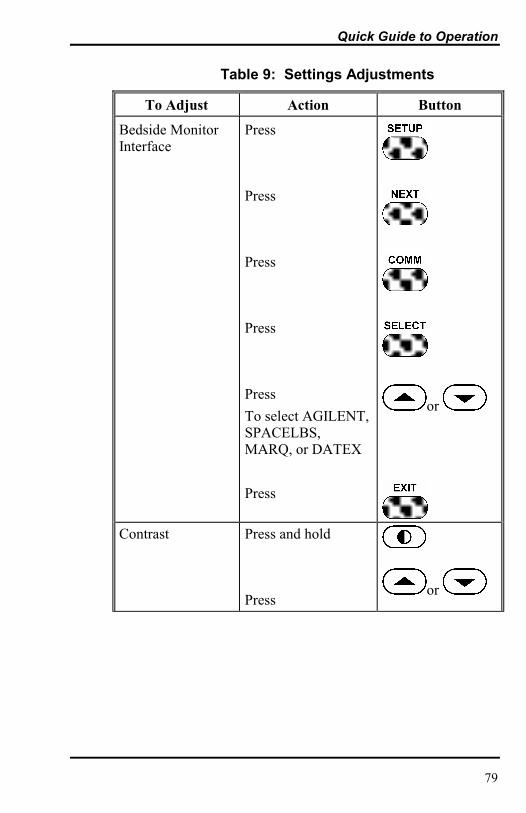
Quick Guide to Operation
79
Table 9: Settings Adjustments
To Adjust Action Button
Bedside MonitorInterface
Press
Press
Press
Press
PressTo select AGILENT,SPACELBS,MARQ, or DATEX
Press
or
Contrast Press and hold
Pressor

Quick Guide to Operation
80
Table 9: Settings Adjustments
To Adjust Action Button
Language Press
Press
Press
Press
Press
or
, Pleth or Blip(magnified) View
Press
Press
Select
Press
or
Pulse BeepVolume
Press and holdor

Quick Guide to Operation
81
Table 9: Settings Adjustments
To Adjust Action Button
SatSeconds Press
Press
Press
Press
to selectSatSeconds
or

Quick Guide to Operation
82
Table 9: Settings Adjustments
To Adjust Action Button
Time and DateSettings
Press
Press
Press
Press(to select setting)
Press
Press (to return tomain menu)
or
, ,
Trends Press
Press
Select desired view

83
PRINCIPLES OF OPERATIONOximetry Overview
OXIMETRY OVERVIEW
Pulse oximetry is based on two principles: that oxyhemoglobinand deoxyhemoglobin differ in their absorption of red andinfrared light (i.e., spectrophotometry), and that the volume ofarterial blood in tissue (and hence, light absorption by that blood)changes during the pulse (i.e., plethysmography). A pulseoximeter determines SpO2 by passing red and infrared light intoan arteriolar bed and measuring changes in light absorptionduring the pulsatile cycle. Red and infrared low-voltage light-emitting diodes (LEDs) in the oximetry sensor serve as lightsources; a photodiode serves as the photodetector.
Because oxyhemoglobin and deoxyhemoglobin differ in lightabsorption, the amount of red and infrared light absorbed byblood is related to hemoglobin oxygen saturation. To identify theoxygen saturation of arterial hemoglobin, the monitor uses thepulsatile nature of arterial flow. During systole, a new pulse ofarterial blood enters the vascular bed, and blood volume and lightabsorption increase. During diastole, blood volume and lightabsorption reach their lowest point. The monitor bases its SpO2measurements on the difference between maximum and minimumabsorption (i.e., measurements at systole and diastole). By doingso, it focuses on light absorption by pulsatile arterial blood,eliminating the effects of nonpulsatile absorbers such as tissue,bone, and venous blood.
Automatic Calibration
Because light absorption by hemoglobin is wavelength dependentand because the mean wavelength of LEDs varies, an oximetermust know the mean wavelength of the sensor�s red LED toaccurately measure SpO2. During manufacturing, the meanwavelength of the red LED is encoded in a resistor in the sensor.
Principles of Operation
84
During monitoring, the instrument�s software reads this resistorvalue and selects coefficients that are appropriate for thewavelength of that individual sensor�s red LED; thesecoefficients are then used to determine SpO2. This resistor valueis read when the monitor is turned on, periodically thereafter, andeach time a new sensor is connected.
Additionally, to compensate for differences in tissue thickness,the light intensity of the sensor�s LEDs is adjusted automatically.
Functional versus Fractional Saturation
This monitor measures functional saturation - oxygenatedhemoglobin expressed as a percentage of the hemoglobin that cantransport oxygen. It does not detect significant amounts ofdysfunctional hemoglobin, such as carboxyhemoglobin ormethemoglobin. In contrast, hemoximeters such as the IL482report fractional saturation - oxygenated hemoglobin expressedas a percentage of all measured hemoglobin, including measureddysfunctional hemoglobins. To compare functional saturationmeasurements to those from an instrument that measuresfractional saturation, fractional measurements must be convertedas follows:
functional saturation = fractional saturation
100 - (%carboxyhemoglobin + %methemoglobin)x100
Measured versus Calculated Saturation
When saturation is calculated from a blood gas partial pressure ofoxygen (PO2), the calculated value may differ from the SpO2measurement of a pulse oximeter. This usually occurs becausethe calculated saturation was not appropriately corrected for theeffects of variables that shift the relationship between PO2 andsaturation (Figure 21): pH, temperature, the partial pressure ofcarbon dioxide (PCO2), 2,3-DPG, and fetal hemoglobin.
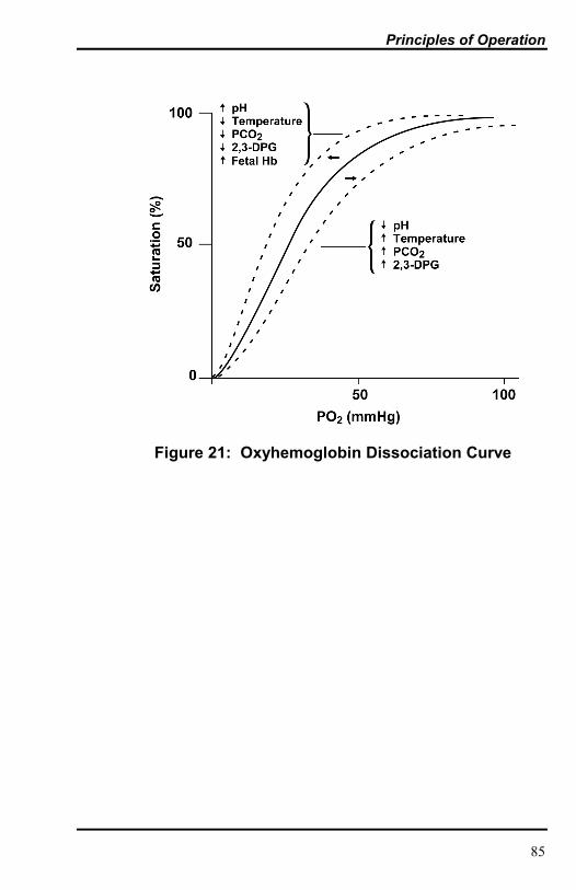
Principles of Operation
85
Figure 21: Oxyhemoglobin Dissociation Curve

[This page intentionally left blank]

87
DATA PORT PROTOCOLOverviewConnecting to the Data PortBaud RateSetting Data Port ProtocolReal-Time Display FormatTrend Data Printout (ASCII Mode)Trend Data Printout (Graph Mode)Nurse CallAnalog Outputs
OVERVIEW
Patient data can be obtained through the data port on the back ofthe N-395 by connecting it to an attached PC or serial printer.
When connecting the N-395 to a printer or PC, verify properoperation before clinical use. Both the N-395 and the printer orPC must be connected to a grounded AC outlet. The N-395protocol setting must be in the ASCII mode as described in the�COMM� paragraph of the Start-Up and Use section.
Any printer or PC connected to the monitor�s data port must becertified according to IEC Standard 950. All combinations ofequipment must be in compliance with IEC Standard 601-1-1systems requirements. Anyone who connects a printer or PC tothe data output port configures a medical system and is thereforeresponsible for ensuring that the system complies with therequirements of system standard IEC Standard 601-1-1 and theelectromagnetic compatibility system standard IEC Standard601-1-2.
CONNECTING TO THE DATA PORT
The N-395 data port may be connected to the printer or PC byusing a cable terminated with an AMP connector (AMP partnumber 747538-1), ferrule (AMP part number 1-747579-2), andcompatible pins (AMP part number 66570-2). The cable shouldbe no more than 25 feet (7.6 meters) in length. The external ITE

Data Port Protocol
88
(Information Technology Equipment) device must be certified toUL-1950 or IEC-60950.
The cable used must have a braided shield providing 100%coverage, such as a Belden cable (Belden part number 9609) orequivalent. The shield must have a 360-degree connection to themetal shell on the N-395�s DB-15 connector and to the connectoron the PC or serial printer. Do not create sharp bends in thecable, as this may tear or break the shielding.
The pinouts (as illustrated in Figure 22) for the data port arelisted in Table 10.
Table 10: Data Port Pinouts
Pin Signal Name
1 RxD+ (RS-422[+] input)2 RxD_232 (RS-232 input)3 TxD_232 (RS-232 output)4 TxD+ (RS-422[+] output)5 Signal Ground (isolated from Earth Ground)6 AN_ SpO2 (analog saturation output)7 NC_NO (relay closure nurse call, normally open)8 NC_NC (relay closure nurse call, normally closed)9 RxD- (RS-422 [-] input)
10 Signal Ground (isolated from Earth Ground)11 Nurse Call (232-level output)12 TxD- (RS-422 [-] output)13 AN-PULSE (analog pulse rate output)14 AN-PLETH (analog pleth wave output)15 NC-COM (relay closure nurse call common lead)
GND is ground, TxD represents the Transmit Data line, and RxDis the Receive Data line.
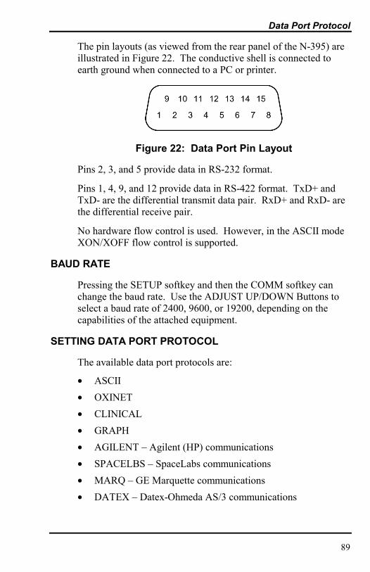
Data Port Protocol
89
The pin layouts (as viewed from the rear panel of the N-395) areillustrated in Figure 22. The conductive shell is connected toearth ground when connected to a PC or printer.
Figure 22: Data Port Pin Layout
Pins 2, 3, and 5 provide data in RS-232 format.
Pins 1, 4, 9, and 12 provide data in RS-422 format. TxD+ andTxD- are the differential transmit data pair. RxD+ and RxD- arethe differential receive pair.
No hardware flow control is used. However, in the ASCII modeXON/XOFF flow control is supported.
BAUD RATE
Pressing the SETUP softkey and then the COMM softkey canchange the baud rate. Use the ADJUST UP/DOWN Buttons toselect a baud rate of 2400, 9600, or 19200, depending on thecapabilities of the attached equipment.
SETTING DATA PORT PROTOCOL
The available data port protocols are:
• ASCII• OXINET• CLINICAL• GRAPH• AGILENT � Agilent (HP) communications• SPACELBS � SpaceLabs communications• MARQ � GE Marquette communications• DATEX � Datex-Ohmeda AS/3 communications

Data Port Protocol
90
Note: Selections for Agilent, SpaceLabs, GE Marquette, andDatex are included in N-395 software versions 1.7 andhigher.
The protocol settings allow the N-395 to communicate withvarious devices. ASCII is used during normal operation and forserial printers. GRAPH is used for graphical trend printoutswhen connected to a serial printer that supports Epson ESCprotocol. Select OXINET when connecting to an Oxinet� IIcentral station network or Score software. The Bedside MonitorInterface selections are AGILENT (for Agilent HP monitors),SPACELBS (for SpaceLab monitors), MARQ (for Marquettemonitors), and DATEX (for Datex-Ohmeda AS/3 monitors). Donot use the CLINICAL setting unless instructed to do so byMallinckrodt�s Technical Services personnel.
REAL-TIME DISPLAY FORMAT
While the N-395 data port protocol setting is set to ASCII (referto Start-Up and Use section), real-time data is continuously sentto the data port on the back of the N-395. Patient data can beobtained through the data port by connecting it to an attached PCor serial printer. When a real-time printout or display is beingtransmitted to a printer or PC, a new line of data is displayedevery 4 seconds. Column headings will be displayed or printedafter every 25 lines, or if one of the values in the column headingchanges.
Note: If the data output stops transmitting, turn the power offand back on again or, if connected to a PC, send an XON(Ctrl-q) to reset the monitor.
An example of a real-time printout is shown in Figure 23.

Data Port Protocol
91
N-395 VERSION 2.0.0.0 CRC: XXXX SpO2 Limit: 70-100% PR Limit: 60-160BPMTIME %SpO2 BPM PA Status12-NOV-99 14:00:05 100 120 5012-NOV-99 14:00:07 100 124 5012-NOV-99 14:00:09 100 190* 52 PS SL PH LB12-NOV-99 14:00:11 100 190* 50 PS SL PH LB12-NOV-99 14:00:13 100 190* 51 PS SL PH LB12-NOV-99 14:00:15 100 190* 50 PS SL PH LB12-NOV-99 14:00:17 100 190* 50 PS SL PH LB12-NOV-99 14:00:19 100 190* 51 PS SL PH LB12-NOV-99 14:00:21 100 190* 53 PS SL PH LB12-NOV-9914:00:23 100 190* 50 PS SL PH LB12-NOV-99 14:00:25 100 190* 50 PS SL PH LB12-NOV-99 14:00:27 - - - - - - - - - SD SL PH LB12-NOV-99 14:00:29 - - - - - - - - - SD SL PH LB12-NOV-99 14:00:31 - - - - - - - - - SD SL PH LB12-NOV-99 14:00:33 - - - - - - - - - SD12-NOV-99 14:00:35 - - - - - - - - - SD12-NOV-99 14:00:37 - - - - - - - - - SD12-NOV-99 14:00:39 - - - - - - - - - SD12-NOV-99 14:00:41 - - - - - - - - - SD12-NOV-99 14:00:43 - - - - - - - - - SD12-NOV-99 14:00:45 - - - - - - - - - SD12-NOV-99 14:00:47 - - - - - - - - - SD12-NOV-99 14:00:49 - - - - - - - - - SDN-395 VERSION 2.0.0.0 CRC: XXXX SpO2 Limit: 70-100% PR Limit: 60-160BPMTIME %SpO2 BPM PA Status12-NOV-99 14:00:51 - - - - - - - - - SDN-395 VERSION 2.0.0.0 CRC: XXXX SpO2 Limit: 70-100% PR Limit: 60-160BPMTIME %SpO2 BPM PA Status12-NOV-99 14:00:53 79* 59* 50 PS SL PL LB12-NOV-99 14:00:55 79* 59* 50 PS SL PL LB
Figure 23: Real-Time Printout
Column Headings
Every 25th line of the data is a column heading.N-395 VERSION 2.0.0.0 CRC: XXXX SpO2 Limit: 70-100% PR Limit: 60-160BPMTIME %SpO2 BPM PA Status
A column heading is also displayed whenever a value of thecolumn heading is changed. There are three column headinglines shown in Figure 23. Using the top row as the starting pointthere are 25 lines before the second column heading is printed.The third column heading was displayed because the SpO2 limitschanged from 70-100% to 80-100%.

Data Port Protocol
92
Data SourceN-395 VERSION 2.0.0.0 CRC: XXXX SpO2 Limit: 70-100% PR Limit: 60-160BPMTIME %SpO2 BPM PA Status
Data in the highlighted box above represents the model numberof the monitor, in this case the N-395.
Software Revision LevelN-395 VERSION 2.0.0.0 CRC: XXXX SpO2 Limit: 70-100% PR Limit: 60-160BPMTIME %SpO2 BPM PA Status
The next data field tells the user the software level, (Version2.0.0.0) and a software verification number (CRC: XXXX).Neither of these numbers should change during normal operation.The numbers may change if the monitor is serviced and receivesa software upgrade.
Alarm LimitsN-395 VERSION 2.0.0.0 CRC: XXXX SpO2 Limit: 70-100% PR Limit: 60-160BPMTIME %SpO2 BPM PA Status
The last data field in the top line indicates the high and the lowalarm limits for %SpO2 and for the pulse rate (PR). In theexample above the low alarm limit for SpO2 is 70% and the highalarm limit is 100%. Pulse Rate alarm limits are 60 and 160bpm.
Column HeadingsN-395 VERSION 2.0.0.0 CRC: XXXX SpO2 Limit: 70-100% PR Limit: 60-160BPMTIME %SpO2 BPM PA Status
Actual column headings are in the second row of the columnheading line. Patient data presented in the chart, from left toright, is the:
• time the patient data was obtained• current %SpO2 value• current Pulse Rate• current Pulse Amplitude• operating status of the N-395.

Data Port Protocol
93
Patient Data and Operating Status
TimeTIME %SpO2 BPM PA Status12-NOV-99 14:00:05 100 120 50
The Time column represents the N-395 real-time clock.
Patient DataN-395 VERSION 2.0.0.0 CRC: XXXX SpO2 Limit: 70-100% PR Limit: 60-160BPMTIME %SpO2 BPM PA Status12-NOV-99 14:00:05 100 120 50
Patient data is highlighted in the display above. Parameter valuesare displayed directly beneath the heading for each parameter. Inthis example the %SpO2 is 100, and the pulse rate is 190 beatsper minute. The �*� next to the 190 indicates that 190 beats perminute is outside of the alarm limits, indicated in the top row, forpulse rate. If no data for a parameter is available three dashes(- - -) will be displayed.
PA is an indication of pulse amplitude. The number can rangefrom 0 to 254. There are no alarm parameters for this value. Itcan be used for trending information as an indication of a changein pulse volume, relative pulse strength, or circulation.
Operating StatusN-395 VERSION 2.0.0.0 CRC: XXXX SpO2 Limit: 70-100% PR Limit: 60-160BPMTIME %SpO2 BPM PA Status12-NOV-99 14:00:11 100 190* 50 PS SL PH LB
The Status column indicates alarm conditions and operatingstatus of the N-395. In this example, the PH means that the pulserate upper alarm limit (Pulse High) has been exceeded. Acomplete listing of the status codes is listed in Table 11. Asmany as 4 codes can be displayed at one time in the Statuscolumn.

Data Port Protocol
94
Table 11: Status Codes
Code Meaning
AO Alarm OffAS Alarm SilenceLB Low BatteryLM Loss of Pulse w/ MotionLP Loss of PulseMO Patient MOtionPH Pulse Rate High Limit AlarmPL Pulse Rate Low Limit AlarmPS Pulse SearchSH Sat High Limit AlarmSL Sat Low Limit AlarmSD Sensor Disconnect
Note: A sensor disconnect will also cause three dashes (- - -) tobe displayed in the patient data section of the display orprintout.
TREND DATA PRINTOUT (ASCII MODE)
The format of data displayed when a trend printout (Figure 24) isrequested is similar to that of the real-time data. The onlydifferences are that �TREND� is displayed in the top row insteadof the �CRC: XXXX� software verification number and there isno �Status� column.
Readings are displayed in 4-second intervals. The values on eachrow are an average for the 4-second period.
At the end of the printout an �Output Complete� line indicatesthat the transmission was successful. If the �Output Complete�line is not present, a corruption of the data may have beendetected and the data should be ignored.

Data Port Protocol
95
N-395 VERSION 2.0.0.0 TREND SpO2 Limit: 70-100% PR Limit: 60-160BPMTIME %SpO2 BPM PA Status12-NOV-99 14:00:05 100 120 15012-NOV-99 14:00:07 100 121 15412-NOV-99 14:00:09 100 120 150Output Complete
Figure 24: Trend Data Printout (ASCII MODE)
Once a trend printout has begun, it cannot be aborted withoutturning off the N-395 or the printer.
TREND DATA PRINTOUT (GRAPH MODE)
The graph mode (Figure 25) disables all printout functionsexcept trend data. Trend printouts will be graphical if connectedto an approved serial printer. Contact Mallinckrodt�s TechnicalServices Department for a list of approved serial printers.
Figure 25: Trend Data Printout (GRAPH MODE)
NURSE CALL
WARNING: The nurse call feature should not be used as theprimary source of alarm notification. The audible and visualalarms of the monitor, used in conjunction with clinical signsand symptoms, are the primary source for notifying medicalpersonnel that an alarm condition exists.
The N-395 provides two different types of nurse call interfaces:an RS-232 level and solid state relay closure. The solid staterelay-based nurse call function is available when the monitor isoperating either on AC power or when powered by battery.
The remote location will be signaled anytime there is an audiblealarm.
Pin 11 on the data port is the RS-232 level nurse call signal andpin 10 is ground (see Table 10). The nurse call polarity(normally high or normally low) and whether the monitor is in

Data Port Protocol
96
alarm determine the voltage between these pins. The nurse callpolarity is set by using the procedures in the Start-up and Usesection. To access the nurse call menu from the main menu,press softkeys SETUP, NEXT, NEXT and NCALL.
When the nurse call polarity setting is normally high (NORM +)and there is no alarm condition, the voltage between pins 11 and10 will be +5 to +12 volts DC. Whenever the monitor is in analarm condition, the output between pins 11 and 10 will be -5 to-12 volts DC. When the setting is normally low (NORM -), thereadings are opposite, as indicated in Table 12.
These voltages are present only when the monitor is operating onAC power.
If the audible alarm has been turned off, or silenced, the nursecall alarm is also silenced.
Table 12: Voltage Between Pins 10 and 11
Alarm State Nurse CallPolarity Setting
Voltage from pins10 to 11
No current alarms Normally high +5 to +12 VDCAlarm condition Normally high -5 to -12 VDCNo current alarms Normally low -5 to -12 VDCAlarm condition Normally low +5 to +12 VDC
Pins 7 and 15 provide a solid state relay that closes when analarm is sounding on the monitor. Pins 8 and 15 provide a solidstate relay that opens when an alarm is sounding. Pin 15 is acommon lead for both relays. The solid state relay operateswhether the monitor is operating on AC power or battery.

Data Port Protocol
97
ANALOG OUTPUTS
The N-395 data port also provides analog voltage outputsbetween pins 6, 13, 14, and ground (pins 5 or 10), which can beused to calibrate instruments such as a chart recorder. Thevoltage represents a specific measured parameter�s current value.The voltage differential varies proportionally from 0 to 1 volt asthe pin�s parameter varies over its full range of values, asindicated in Table 13.
Table 13: Analog Pinouts
Pin Parameter Parameter Range
6 %SpO2 0 - 100%13 Pulse rate 0 - 250 bpm14 Pleth wave 0 - 255
For example, as the current value of %SpO2 varies from 0 to100%, the voltage from pin 6 to ground (pin 10) would vary from0 to 1 volt. A voltage of .94 volts indicates a current %SpO2value of 94.
The analog output calibration function can be accessed from themain menu by pressing SETUP, NEXT, NEXT, ANALOG.Selecting �0 VOLT� or �1 VOLT� causes that voltage to appearat pins 6, 3, or 10. Selecting �STEP� causes the voltage toincrease from 0 to 1 volt at 1/10th-volt increments, with each steplasting at least 1 second.
Qualified service personnel using the procedure described in theN-395 service manual can perform calibration of the analogoutput and the attached device.

[This page intentionally left blank]

99
INDEX
4
40-Second Trend Table · 50
A
Accessories · 12Adjustable
Settings · 38Agilent (HP) Communications · 54Alarm Limits
Changing · 43Viewing Current · 42
Alarm Limits Changed Indicator · 46Alarm Management
SatSeconds · 35Alarm Silence Duration · 39Alarm Silence Reminder · 40Alarm Volume · 39Alarms
Description · 34High-Priority · 34Low-Priority · 34Medium-Priority · 34
ANALOG · 58Analog Output · 97ASCII Mode · 94ASCII MODE · 51Automatic Shutdown · 33
B
Basic Operation · 28Battery Operation · 61Biocompatibility Testing · 24Buttons
Adjust Down · 7Adjust Up · 7Alarm Silence · 7Contrast · 7
Power On/Off · 7Softkey · 7
C
Changing Alarm Limits · 43Cleaning · 72CLOCK · 52Codes
Error · 65COMM · 53Connecting the N-395 · 19Connecting to the Data Port · 87Contrast · 31Corrective Actions · 67
D
Data PortBaud Rate · 89Connection To · 87Pin Layout · 89Pinouts · 88
Data Port Protocol · 87Datex Communications · 57Default Settings · 58DELETE · 51Disabling Audible Alarms · 40Discharged Battery · 19Display Format
Real-Time · 90Disposal of Device Components · 62
E
EMI Interference · 70Error Codes · 65

Index
100
F
Front Panel · 5
G
GCX Mounting Plate · 13GCX Poly-mount · 14, 15GCX Roll Stand Poly-mount · 16GCX Utility Basket · 17GRAPH MODE · 52
H
Histogram · 49
I
Inaccurate measurements · 25, 63Indicators
AC Power · 8Alarm Limits Changed · 46Alarm Silence · 9Alarm Silence Reminder · 10Confirmation Tone · 10High Priority Alarm · 9Invalid Button Pressed · 9Low Battery · 8Low Priority Alarm · 10Medium Priority Alarm · 9Motion · 9Percent SpO2 · 8Power-On Self-Test Passed · 9Pulse Amplitude · 8Pulse Beep · 10Pulse Rate · 8Pulse Search · 9SatSeconds · 9Valid Button Press · 9Volume Setting Tone · 10
Initial Power-Up · 32Inspection · 11Intended Use · 3
L
LANG · 57Language Selection · 21LIGHT · 58Limits · 42Limits Menu · 43Loss-of-pulse · 25Low Battery Indicator · 61Low Peripheral Perfusion · 26
M
Maintenance · 72Marquette Communications · 56Menu Structure · 41Messages
Disallowed on Battery · 67Disallowed on Low Battery · 67Invalid Silence Duration · 67Invalid SpO2 Limit · 67Reading Trend · 67Sensor Disconnected · 66Sensor Off · 67
Monitor Setup · 19Monitoring Mode · 31
N
NCALL · 58NEXT · 51Nurse Call · 60, 95
O
Obtaining Technical Assistance · 71Operating Conditions · 3Operating Principles · 3Operation
Battery · 61Oximetry Overview · 83

Index
101
P
Packing List · 11Patient Cosiderations
Impact of Readings · 62Patient Movement · 26Performance Considerations · 25, 62Performance Verification · 11, 72Periodic Maintenance · 72Poor Perfusion · 26Power-On Self-Test (POST) · 28Principles of Operation · 83PRINT · 51Printout
Alarm Limits · 92ASCII Mode · 94Column Headings · 91Data Source · 92GRAPH Mode · 95Operating Status · 93Patient Data · 93Software Revision Level · 92
Pulse Beep Volume · 38Pulse Search · 32
Q
Quick Guide to Operation · 77
R
Real-Time Display Format · 90Real-Time Printout · 91Rear Panel · 6Returning the N-395 · 71
S
Safety Checks · 72Safety Information · 1SatSeconds
Alarm Management · 35Determining Setting · 37
Display · 38Safety Net · 37
SaturationCalculated · 84Fractional · 84Functional · 84Measured · 84
Selecting a Sensor · 23Sensor
Selection · 23Sensor Disconnected · 33Sensor Off · 33Sensors · 23Service · 72Settings
Adult-Pediatric · 30Ajustable · 38Alarm Silence Duration · 39Alarm Silence Reminder · 40Alarm Volume · 39Default · 58Disabling Audible Alarms · 40Neonatal · 30Pulse Beep Volume · 38
SETUP · 52Setup Menu · 45Soft Sided Carrying Case · 18Softkeys
ANALOG · 58CLOCK · 52COMM · 53DELETE · 51LANG · 57LIGHT · 58NCALL · 58NEXT · 51PRINT · 51SETUP · 52VIEW · 52ZOOM · 50
Software Revision Level · 92SpaceLabs Communications · 55Specifications · 73
Accuracy · 73Compliance · 76Electrical · 74Environmental Conditions · 75Measurement Range · 73Performance · 73Physical Characteristics · 75

Index
102
Pulse Rate · 74SpO2 · 73
Start Up and Use · 27Status Codes · 94Symbols
Date of Manufaqcture · 6Equipotential (Ground) Terminal · 6Fuse Replacement · 6See Instructions · 6Type BF Equipment · 6
SymboplsData Interface · 6
T
Taking Measurements · 33Technical Assistance · 71Trend · 46
Histogram · 49View · 48ZOOM · 50
Trend Data Printout (ASCII Mode) ·94
Trend Data Printout (GRAPH Mode) ·95
Trend Menu · 44
Trend Scale · 47Trends
40-Second Trend Table · 50Troubleshooting · 65
U
Unpacking · 11
V
VerificationPerformance · 11, 72
View · 52Trend · 48
Viewing Current Alarm Limits · 42Voltage Selector Switch · 19
Z
ZOOM · 50