Embed Size (px)
Citation preview

NBC112V1.RV4 20 May 1994
N E P A L N A T I O N A L B U I L D I N G C O D E
NBC 112 : 1994
TIMBER
Government of Nepal Ministry of Physical Planning and Works
Department of Urban Development and Building Construction Babar Mahal, Kathmandu, NEPAL
Reprinted : 2064
NBC112V1.RV4 20 May 1994
N E P A L N A T I O N A L B U I L D I N G C O D E
NBC 112 : 1994
TIMBER
tTsflng >L % sf] ;/sf/ -dlGqkl/ifb\_ sf] ldlt @)^).$.!@ sf] lg0f{ofg';f/ :jLs[t
Government of Nepal Ministry of Physical Planning and Works
Department of Urban Development and Building Construction Babar Mahal, Kathmandu, NEPAL
Reprinted : 2064
This publication represents a standard of good practice and therefore takes the form of recommendations. Compliance with it does not confer immunity from relevant legal requirements, including bylaws

NBC112V1.RV4 20 May 1994
Preface This Nepal Standard was prepared during 1993 as part of a project to prepare a National Building Code for Nepal. In 1988 the Ministry of Housing and Physical Planning (MHPP), conscious of the growing needs of Nepal's urban and shelter sectors, requested technical assistance from the United Nations Development Programme and their executing agency, United Nations Centre for Human Settlements (UNCHS). A programme of Policy and Technical Support was set up within the Ministry (UNDP Project NEP/88/054) and a number of activities have been undertaken within this framework. The 1988 earthquake in Nepal, and the resulting deaths and damage to both housing and schools, again drew attention to the need for changes and improvement in current building construction and design methods. Until now, Nepal has not had any regulations or documents of its own setting out either requirements or good practice for achieving satisfactory strength in buildings. In late 1991 the MHPP and UNCHS requested proposals for the development of such regulations and documents from international organisations in response to terms of reference prepared by a panel of experts. This document has been prepared by the subcontractor's team working within the Department of Building, the team including members of the Department and the MHPP. As part of the proposed management and implementation strategy, it has been prepared so as to conform with the general presentation requirements of the Nepal Bureau of Standards and Metrology. The subproject has been undertaken under the aegis of an Advisory Panel to the MHPP. The Advisory Panel consisted of :
Mr. UB Malla, Joint Secretary, MHPP Chairman Director General, Department of Building (Mr. LR Upadhyay) Member Mr. AR Pant, Under Secretary, MHPP Member Director General, Department of Mines & Geology (Mr. PL Shrestha) Member Director General, Nepal Bureau of Standards & Metrology (Mr. PB Manandhar) Member Dean, Institute of Engineering, Tribhuvan University (Dr. SB Mathe) Member Project Chief, Earthquake Areas Rehabilitation & Reconstruction Project Member President, Nepal Engineers Association Member Law Officer, MHPP (Mr. RB Dange) Member
Representative, Society of Consulting Architectural & Engineering Firms (SCAEF) Member
i
NBC112V1.RV4 20 May 1994
Representative, Society of Nepalese Architects (SONA) Member Deputy Director General, Department of Building, (Mr. JP Pradhan) Member-Secretary
The Subcontractor was BECA WORLEY INTERNATIONAL CONSULTANTS LTD. of New Zealand in conjunction with subconsultants who included : Golder Associates Ltd., Canada SILT Consultants P. Ltd., Nepal TAEC Consult (P.) Ltd., Nepal Urban Regional Research, USA Principal inputs to this standard came from : Mr. AM Tuladhar, DoB, HMGN Dr. AS Arya, Professor Emeritus, University of Roorkee, India Dr. RD Sharpe, BECA (Team Leader) Revisions and Updated to this code came from : Mr. Purna P. Kadariya, DG, DUDBC Mr. Kishore Thapa, DDG DUDBC Mr. Mani Ratna Tuladhar, Sr. Div. Engineer, DUDBC Mr. Jyoti Prasad Pradhan, Ex. DDG, DOB Mr. Bhubaneswor Lal Shrestha, Ex. DDG, DOB Mr. Uttam Shrestha, Architect, Architects’ Module Pvt. Ltd. Mr. Manohar Lal Rajbhandhari, Sr. Structural Engineer, MR Associates Mr. Amrit Man Tuladhar, Civil Engineer, DUDBC
ii
NBC112V1.RV4 20 May 1994
TABLE OF CONTENTS Preface......... ................................................................................................................................................ i 0 Foreword ....................................................................................................................................... v 0.1 Design Aspect ................................................................................................................... v 0.2 Related Codes ................................................................................................................... v 1 Scope .............................................................................................................................................. 1 1.1 Coverage .......................................................................................................................... 1 1.2 Limitation......................................................................................................................... 1 2 Interpretation ............................................................................................................................... 1 2.1 General.............................................................................................................................. 1 2.2 Terminology ..................................................................................................................... 1 2.2.1 Definition of Defects in Timber......................................................................... 2 2.3 Symbols............................................................................................................................. 3 3 Materials........................................................................................................................................ 6 4 Moisture Content in Timber....................................................................................................... 6 5 Sawn Timber.................................................................................................................. ................ 6 5.1 Sizes……………….......................................................................................................... 6 5.2 Tolerances......................................................................................................................... 6 5.3 Location of Defects .......................................................................................................... 6 6 Design Considerations ............................................................................................................... 10 6.1 General............................................................................................................................ 10 6.2 Loads ............................................................................................................................... 10 6.2.1 Load Combination ........................................................................................... 10 6.3 Flexural Members ......................................................................................................... 10 6.3.1 Effective Span ................................................................................................... 10 6.3.2 Form Factors for Flexural Members ............................................................ 10 6.4 Deflection........................................................................................................................ 11
iii
NBC112V1.RV4 20 May 1994
7 Columns....................................................................................................................................... 11 7.1 Solid Columns................................................................................................................ 11 7.2 Long Columns................................................................................................................ 12 7.3 Slenderness Ratio ............................................................................................................ 12 7.4 Permissible Load ........................................................................................................... 12 8 Design of Common Steel Wire Nail Joints.............................................................................. 13 8.1 Dimensions of Members ............................................................................................... 13 8.1.1 Minimum Thickness ....................................................................................... 13 8.1.2 Maximum Thickness ...................................................................................... 13 8.1.3 Minimum Depth.............................................................................................. 13 8.2 Length of Members....................................................................................................... 13 8.3 Width of Members ........................................................................................................ 13 8.4 Spacing............................................................................................................................ 13 8.5 Lengthening-Joints........................................................................................................ 13 8.6 Specification and Diameter of Nails............................................................................ 14 8.6.1 Nails ................................................................................................................... 14 8.6.2 Nail Diameter................................................................................................... 14 8.6.3 Nail Length....................................................................................................... 14 8.6.4 Numbers of Nails............................................................................................. 14 8.6.5 Spacing of Nails ............................................................................................... 14 9 Design of Bolted Joints .............................................................................................................. 15 9.1 General............................................................................................................................ 15 9.2 Design Considerations .................................................................................................. 15 9.3 Arrangement of Bolts.................................................................................................... 15
9.3.1 Spacing ............................................................................................................. 15 9.3.2 Staggering ........................................................................................................ 16 9.3.3 Bolt Holes ......................................................................................................... 16 10 Glue Laminated Timber ........................................................................................................... 16 10.1 Subjected to Bending ...................................................................................................... 16
iv
NBC112V1.RV4 20 May 1994
0. Foreword 0.1 Design Aspect
This standard covers the general principle involved in the design of structural timber in buildings. It also covers the specifications for structural timber for use in buildings including, classification of such timber into suitable grades, as well as nail joint timber construction.
0.2 Related Codes
The requirement of this section shall be applied in conjunction with the Indian Standard IS: 883-1970 Code of Practice for Design of Structural Timber in Building” (Third revision) and IS: 2366-1983 Code of Practice for Nail-Jointed Timber Construction (First Revision).
v
NBC112V1.RV4 20 May 1994
1 Scope 1.1 Coverage
This standard provides a Code of Practice for the structural design of timber in buildings of Nepal.
1.2 Limitation
This section do not covers anti-termite timber, use of plywood, timber in pile foundation.
2 Interpretation 2.1 General 2.1.1 In this standard the word "shall" indicates a requirement that is to be adopted in
order to comply with the Standard, while the word "should" indicates recommended practice.
2.1.2 Commentary clauses are prefaced by the letter C and the number of the
appropriate clause subject to comment. 2.2 Terminology
The terminology given IS : 883-1970 in clauses 2.0 to 2.19 will apply except as stated here below.
BOX COLUMN means a column made of four planks connected together so as to have
hollow core inside. The core is blocked by the solid pieces of timber at its ends and at least one intermediate point.
BUILD UP - SOLID COLUMN means those built up by spiking, nailing or bolting
together planks or square section. The planks must be fastened together at intervals not greater than six times their thickness. The allowable stress on such a column is conservatively taken as 80 % of that of solid column.
CASE HARDENING means a condition of timber during seasoning in which the
different layers of wood are under stress, by being under compression across the grain.
DURATION OF LOADING means the period during which timber structure is stressed as consequence of the loads applied to it.
GREEN TIMBER means timber in which the moisture content is above its
fibre-saturation point.
1
NBC112V1.RV4 20 May 1994
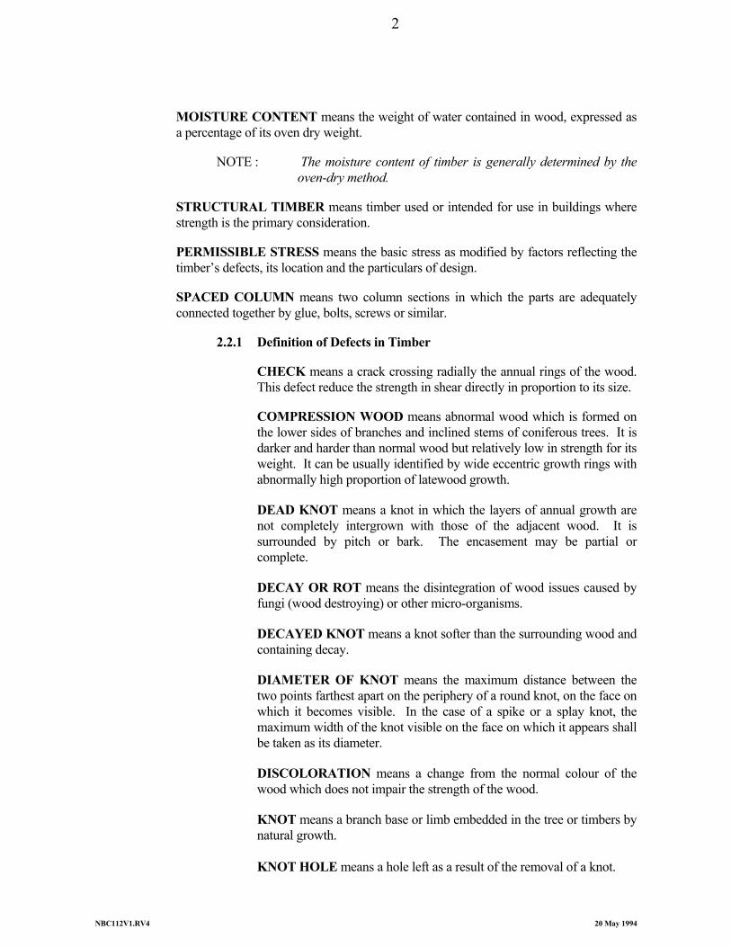
MOISTURE CONTENT means the weight of water contained in wood, expressed as a percentage of its oven dry weight.
NOTE : The moisture content of timber is generally determined by the
oven-dry method.
STRUCTURAL TIMBER means timber used or intended for use in buildings where strength is the primary consideration.
PERMISSIBLE STRESS means the basic stress as modified by factors reflecting the timber’s defects, its location and the particulars of design.
SPACED COLUMN means two column sections in which the parts are adequately connected together by glue, bolts, screws or similar.
2.2.1 Definition of Defects in Timber
CHECK means a crack crossing radially the annual rings of the wood. This defect reduce the strength in shear directly in proportion to its size.
COMPRESSION WOOD means abnormal wood which is formed on
the lower sides of branches and inclined stems of coniferous trees. It is darker and harder than normal wood but relatively low in strength for its weight. It can be usually identified by wide eccentric growth rings with abnormally high proportion of latewood growth.
DEAD KNOT means a knot in which the layers of annual growth are
not completely intergrown with those of the adjacent wood. It is surrounded by pitch or bark. The encasement may be partial or complete.
DECAY OR ROT means the disintegration of wood issues caused by
fungi (wood destroying) or other micro-organisms.
DECAYED KNOT means a knot softer than the surrounding wood and containing decay.
DIAMETER OF KNOT means the maximum distance between the
two points farthest apart on the periphery of a round knot, on the face on which it becomes visible. In the case of a spike or a splay knot, the maximum width of the knot visible on the face on which it appears shall be taken as its diameter.
DISCOLORATION means a change from the normal colour of the
wood which does not impair the strength of the wood.
KNOT means a branch base or limb embedded in the tree or timbers by natural growth.
KNOT HOLE means a hole left as a result of the removal of a knot.
2
NBC112V1.RV4 20 May 1994
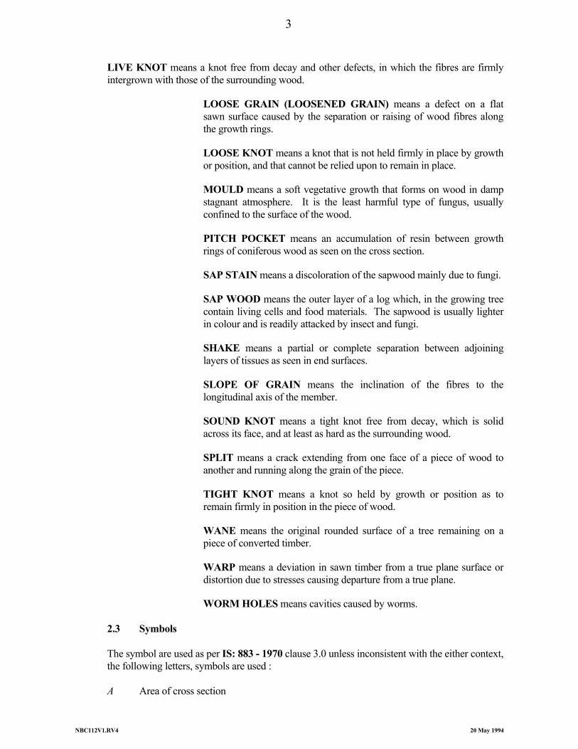
LIVE KNOT means a knot free from decay and other defects, in which the fibres are firmly intergrown with those of the surrounding wood.
LOOSE GRAIN (LOOSENED GRAIN) means a defect on a flat
sawn surface caused by the separation or raising of wood fibres along the growth rings.
LOOSE KNOT means a knot that is not held firmly in place by growth
or position, and that cannot be relied upon to remain in place.
MOULD means a soft vegetative growth that forms on wood in damp stagnant atmosphere. It is the least harmful type of fungus, usually confined to the surface of the wood.
PITCH POCKET means an accumulation of resin between growth
rings of coniferous wood as seen on the cross section.
SAP STAIN means a discoloration of the sapwood mainly due to fungi.
SAP WOOD means the outer layer of a log which, in the growing tree contain living cells and food materials. The sapwood is usually lighter in colour and is readily attacked by insect and fungi.
SHAKE means a partial or complete separation between adjoining
layers of tissues as seen in end surfaces.
SLOPE OF GRAIN means the inclination of the fibres to the longitudinal axis of the member.
SOUND KNOT means a tight knot free from decay, which is solid
across its face, and at least as hard as the surrounding wood.
SPLIT means a crack extending from one face of a piece of wood to another and running along the grain of the piece.
TIGHT KNOT means a knot so held by growth or position as to
remain firmly in position in the piece of wood.
WANE means the original rounded surface of a tree remaining on a piece of converted timber.
WARP means a deviation in sawn timber from a true plane surface or
distortion due to stresses causing departure from a true plane. WORM HOLES means cavities caused by worms. 2.3 Symbols The symbol are used as per IS: 883 - 1970 clause 3.0 unless inconsistent with the either context,
the following letters, symbols are used : A Area of cross section
3
NBC112V1.RV4 20 May 1994
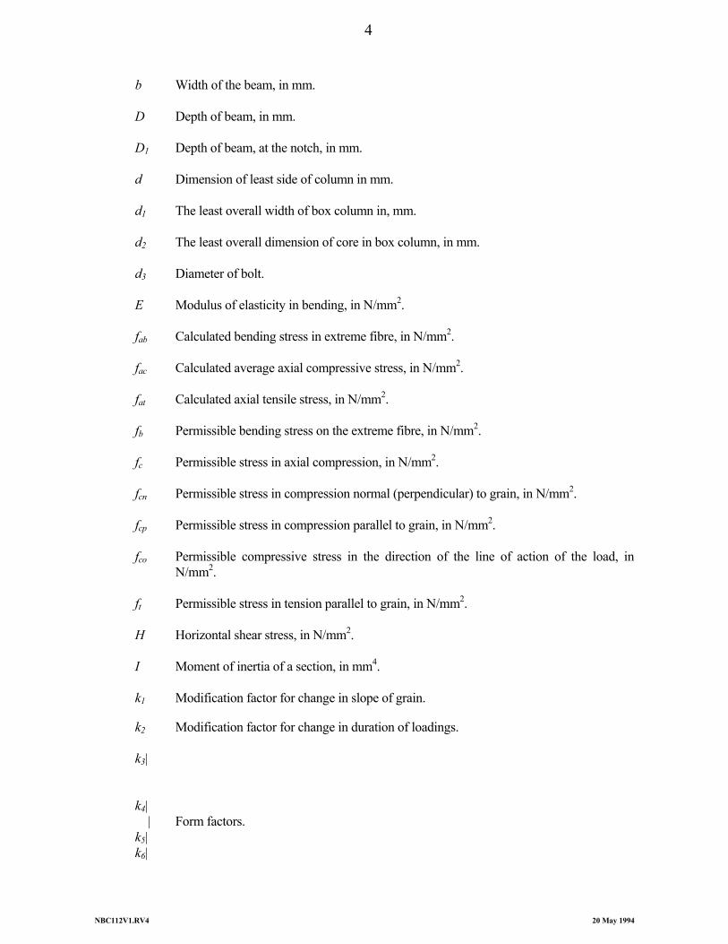
b Width of the beam, in mm. D Depth of beam, in mm. D1 Depth of beam, at the notch, in mm. d Dimension of least side of column in mm. d1 The least overall width of box column in, mm. d2 The least overall dimension of core in box column, in mm. d3 Diameter of bolt. E Modulus of elasticity in bending, in N/mm2. fab Calculated bending stress in extreme fibre, in N/mm2. fac Calculated average axial compressive stress, in N/mm2. fat Calculated axial tensile stress, in N/mm2. fb Permissible bending stress on the extreme fibre, in N/mm2. fc Permissible stress in axial compression, in N/mm2. fcn Permissible stress in compression normal (perpendicular) to grain, in N/mm2. fcp Permissible stress in compression parallel to grain, in N/mm2. fco Permissible compressive stress in the direction of the line of action of the load, in
N/mm2. ft Permissible stress in tension parallel to grain, in N/mm2. H Horizontal shear stress, in N/mm2. I Moment of inertia of a section, in mm4. k1 Modification factor for change in slope of grain.
k2 Modification factor for change in duration of loadings. k3| k4| | Form factors. k5| k6|
4

NBC112V1.RV4 20 May 1994
k7 Modification factor for bearing stress. k8 Constant equal to E702.0 fcp k9 Constant equal to
cpqf
UE5
k10 Constant equal to
cpfE5.2
L Span of beam or truss, in mm. n Shank diameter of the nail. p1 Ratio of the thickness of the compression flange to the depth of the beam. Q Static moment of area above or below the neutral axis about neutral axis, in mm3. q A constant for particular thickness of plank q1 Ratio of the total thickness of web or webs to the overall width of the beam. S Effective length of solid and box columns in mm, distance between points of lateral
support of spaced column, in mm. t Nominal thickness of planks used in forming box type column in mm. U Constant for a particular thickness of the plank V Vertical and reaction or shear at a section in kN. Y A factor determining the value of form factor k4 φ Angle of load to grain direction.
2/π
0.702
5
NBC112V1.RV4 20 May 1994
6
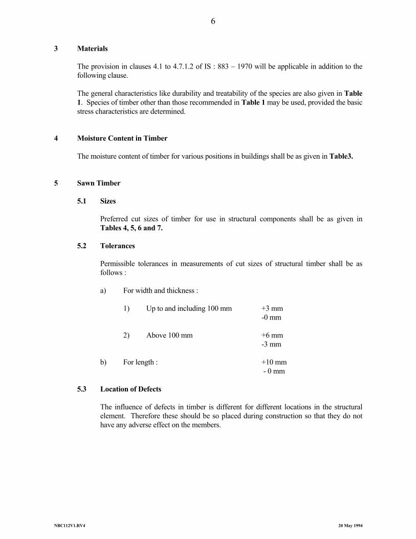
3 Materials The provision in clauses 4.1 to 4.7.1.2 of IS : 883 – 1970 will be applicable in addition to the
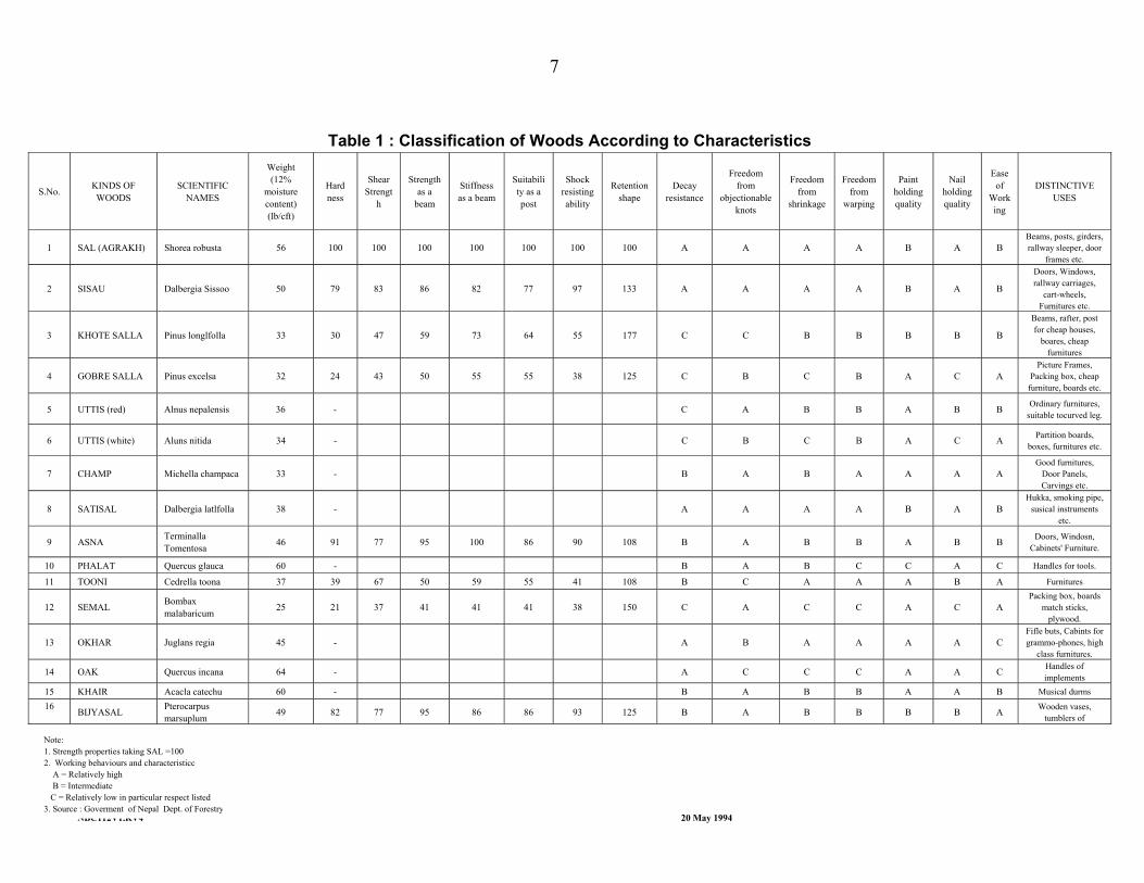
following clause. The general characteristics like durability and treatability of the species are also given in Table
1. Species of timber other than those recommended in Table 1 may be used, provided the basic stress characteristics are determined.
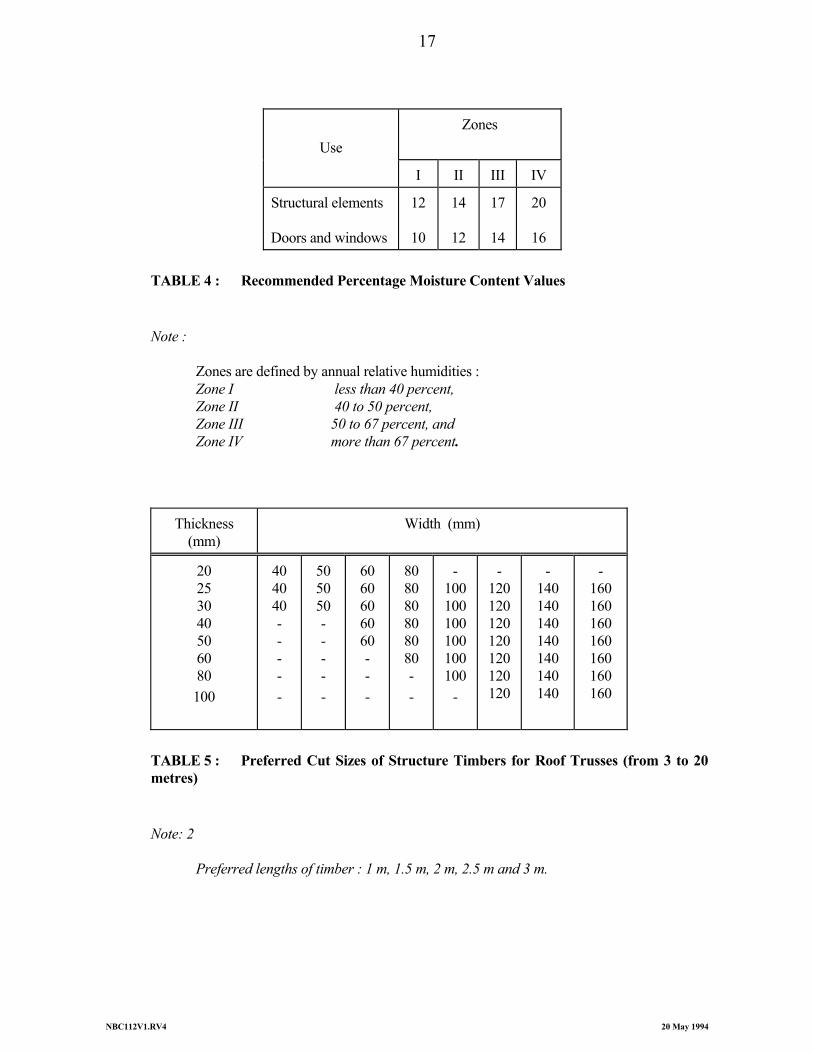
4 Moisture Content in Timber The moisture content of timber for various positions in buildings shall be as given in Table3. 5 Sawn Timber 5.1 Sizes
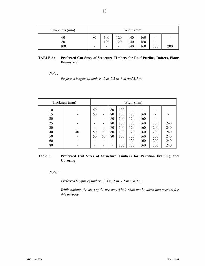
Preferred cut sizes of timber for use in structural components shall be as given in Tables 4, 5, 6 and 7.
5.2 Tolerances
Permissible tolerances in measurements of cut sizes of structural timber shall be as follows :
a) For width and thickness : 1) Up to and including 100 mm +3 mm -0 mm 2) Above 100 mm +6 mm -3 mm b) For length : +10 mm - 0 mm 5.3 Location of Defects
The influence of defects in timber is different for different locations in the structural element. Therefore these should be so placed during construction so that they do not have any adverse effect on the members.
NBC112V1.RV4 20 May 1994
Table 1 : Classification of Woods According to Characteristics
S.No. KINDS OF WOODS
SCIENTIFIC NAMES
Weight (12%
moisture content) (lb/cft)
Hard ness
Shear Strengt
h
Strength as a
beam
Stiffness as a beam
Suitability as a post
Shock resisting ability
Retention shape
Decay resistance
Freedom from
objectionable knots
Freedom from
shrinkage
Freedom from
warping
Paint holding quality
Nail holding quality
Ease of
Working
DISTINCTIVE USES
1 SAL (AGRAKH) Shorea robusta 56 100 100 100 100 100 100 100 A A A A B A B Beams, posts, girders, rallway sleeper, door
frames etc.
2 SISAU Dalbergia Sissoo 50 79 83 86 82 77 97 133 A A A A B A B
Doors, Windows, rallway carriages,
cart-wheels, Furnitures etc.
3 KHOTE SALLA Pinus longlfolla 33 30 47 59 73 64 55 177 C C B B B B B
Beams, rafter, post for cheap houses,
boares, cheap furnitures
4 GOBRE SALLA Pinus excelsa 32 24 43 50 55 55 38 125 C B C B A C A Picture Frames,
Packing box, cheap furniture, boards etc.
5 UTTIS (red) Alnus nepalensis 36 - C A B B A B B Ordinary furnitures, suitable tocurved leg.
6 UTTIS (white) Aluns nitida 34 - C B C B A C A Partition boards, boxes, furnitures etc.
7 CHAMP Michella champaca 33 - B A B A A A A Good furnitures,
Door Panels, Carvings etc.
8 SATISAL Dalbergia latlfolla 38 - A A A A B A B Hukka, smoking pipe,
susical instruments etc.
9 ASNA Terminalla Tomentosa 46 91 77 95 100 86 90 108 B A B B A B B Doors, Windosn,
Cabinets' Furniture.
10 PHALAT Quercus glauca 60 - B A B C C A C Handles for tools.
11 TOONI Cedrella toona 37 39 67 50 59 55 41 108 B C A A A B A Furnitures
12 SEMAL Bombax malabaricum 25 21 37 41 41 41 38 150 C A C C A C A
Packing box, boards match sticks,
plywood.
13 OKHAR Juglans regia 45 - A B A A A A C Fifle buts, Cabints for grammo-phones, high
class furnitures.
14 OAK Quercus incana 64 - A C C C A A C Handles of implements
15 KHAIR Acacla catechu 60 - B A B B A A B Musical durms
16 BIJYASAL Pterocarpus marsuplum 49 82 77 95 86 86 93 125 B A B B B B A Wooden vases,
tumblers of
Note: 1. Strength properties taking SAL =100 2. Working behaviours and characteristicc A = Relatively high B = Intermediate C = Relatively low in particular respect listed 3. Source : Goverment of Nepal Dept. of Forestry
7
NBC112V1.RV4 20 May 1994
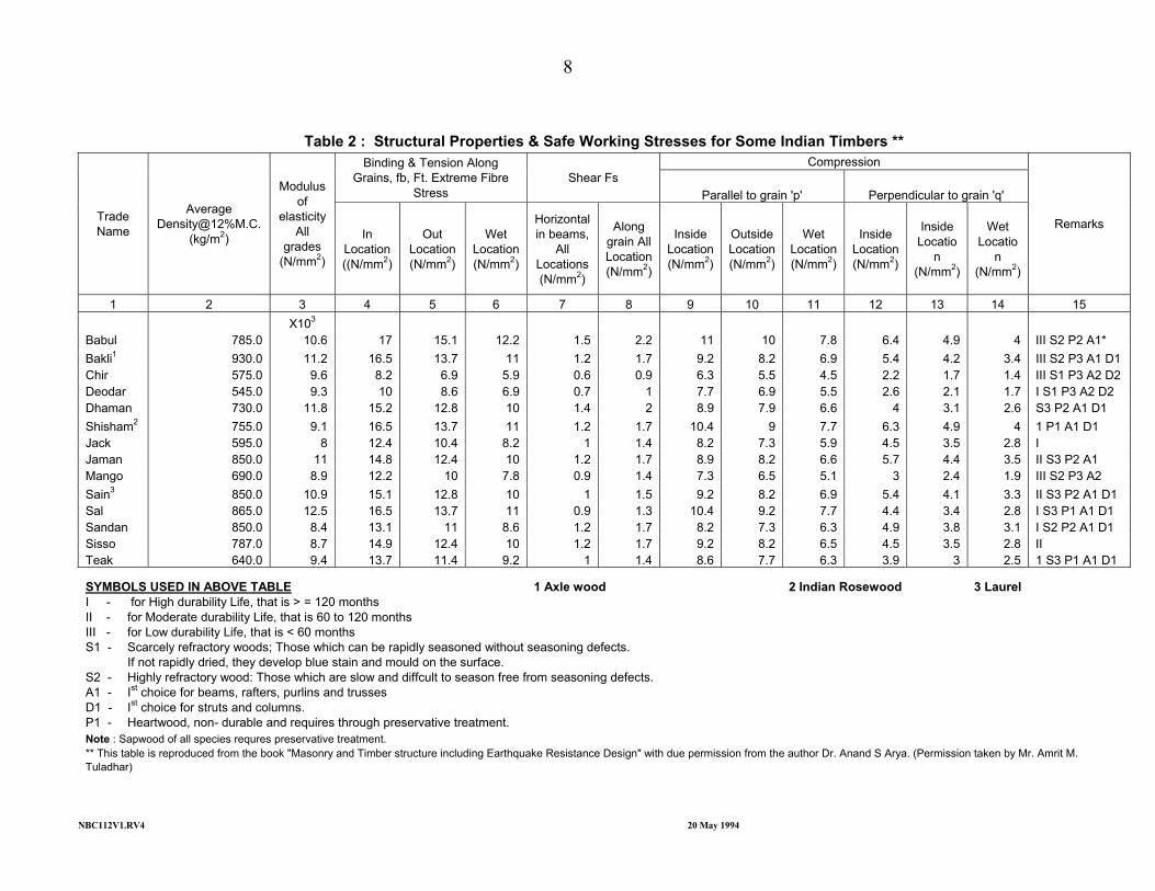
Table 2 : Structural Properties & Safe Working Stresses for Some Indian Timbers ** Compression Binding & Tension Along
Grains, fb, Ft. Extreme Fibre Stress
Shear Fs Parallel to grain 'p' Perpendicular to grain 'q'
Trade Name
Average Density@12%M.C.
(kg/m2)
Modulus of
elasticity All
grades (N/mm2)
In Location ((N/mm2)
Out Location (N/mm2)
Wet Location (N/mm2)
Horizontal in beams,
All Locations (N/mm2)
Along grain All Location (N/mm2)
Inside Location (N/mm2)
Outside Location (N/mm2)
Wet Location (N/mm2)
Inside Location (N/mm2)
Inside Locatio
n (N/mm2)
Wet Locatio
n (N/mm2)
Remarks
1 2 3 4 5 6 7 8 9 10 11 12 13 14 15 X103
Babul 785.0 10.6 17 15.1 12.2 1.5 2.2 11 10 7.8 6.4 4.9 4 III S2 P2 A1* Bakli1 930.0 11.2 16.5 13.7 11 1.2 1.7 9.2 8.2 6.9 5.4 4.2 3.4 III S2 P3 A1 D1 Chir 575.0 9.6 8.2 6.9 5.9 0.6 0.9 6.3 5.5 4.5 2.2 1.7 1.4 III S1 P3 A2 D2 Deodar 545.0 9.3 10 8.6 6.9 0.7 1 7.7 6.9 5.5 2.6 2.1 1.7 I S1 P3 A2 D2 Dhaman 730.0 11.8 15.2 12.8 10 1.4 2 8.9 7.9 6.6 4 3.1 2.6 S3 P2 A1 D1 Shisham2 755.0 9.1 16.5 13.7 11 1.2 1.7 10.4 9 7.7 6.3 4.9 4 1 P1 A1 D1 Jack 595.0 8 12.4 10.4 8.2 1 1.4 8.2 7.3 5.9 4.5 3.5 2.8 I Jaman 850.0 11 14.8 12.4 10 1.2 1.7 8.9 8.2 6.6 5.7 4.4 3.5 II S3 P2 A1 Mango 690.0 8.9 12.2 10 7.8 0.9 1.4 7.3 6.5 5.1 3 2.4 1.9 III S2 P3 A2 Sain3 850.0 10.9 15.1 12.8 10 1 1.5 9.2 8.2 6.9 5.4 4.1 3.3 II S3 P2 A1 D1 Sal 865.0 12.5 16.5 13.7 11 0.9 1.3 10.4 9.2 7.7 4.4 3.4 2.8 I S3 P1 A1 D1 Sandan 850.0 8.4 13.1 11 8.6 1.2 1.7 8.2 7.3 6.3 4.9 3.8 3.1 I S2 P2 A1 D1 Sisso 787.0 8.7 14.9 12.4 10 1.2 1.7 9.2 8.2 6.5 4.5 3.5 2.8 II Teak 640.0 9.4 13.7 11.4 9.2 1 1.4 8.6 7.7 6.3 3.9 3 2.5 1 S3 P1 A1 D1
SYMBOLS USED IN ABOVE TABLE 1 Axle wood 2 Indian Rosewood 3 Laurel I - for High durability Life, that is > = 120 months II - for Moderate durability Life, that is 60 to 120 months III - for Low durability Life, that is < 60 months S1 - Scarcely refractory woods; Those which can be rapidly seasoned without seasoning defects. If not rapidly dried, they develop blue stain and mould on the surface. S2 - Highly refractory wood: Those which are slow and diffcult to season free from seasoning defects. A1 - Ist choice for beams, rafters, purlins and trusses D1 - Ist choice for struts and columns. P1 - Heartwood, non- durable and requires through preservative treatment. Note : Sapwood of all species requres preservative treatment. ** This table is reproduced from the book "Masonry and Timber structure including Earthquake Resistance Design" with due permission from the author Dr. Anand S Arya. (Permission taken by Mr. Amrit M. Tuladhar)
8
NBC112V1.RV4 20 May 1994
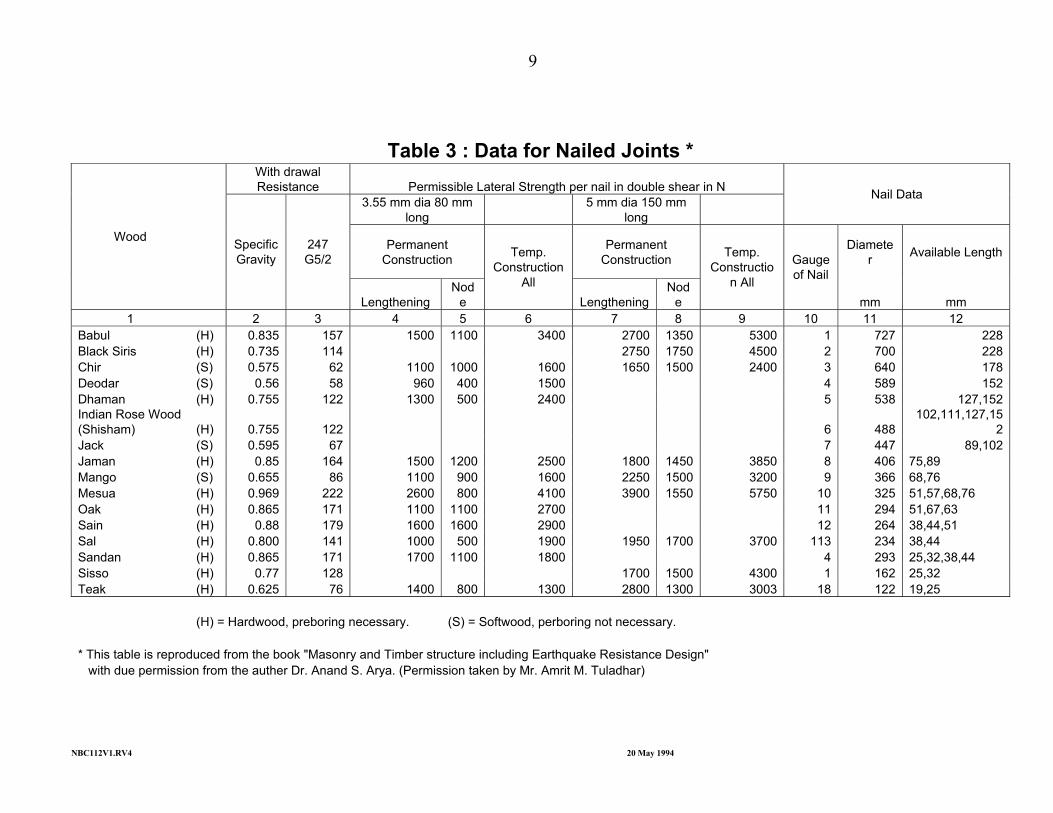
Table 3 : Data for Nailed Joints *
With drawal Resistance Permissible Lateral Strength per nail in double shear in N
3.55 mm dia 80 mm long
5 mm dia 150 mm long
Nail Data
Permanent Construction
Permanent Construction
Diameter Available Length
Wood
Specific Gravity
247 G5/2
Lengthening Nod
e
Temp. Construction
All Lengthening
Node
Temp. Constructio
n All
Gauge of Nail
mm mm 1 2 3 4 5 6 7 8 9 10 11 12
Babul (H) 0.835 157 1500 1100 3400 2700 1350 5300 1 727 228 Black Siris (H) 0.735 114 2750 1750 4500 2 700 228 Chir (S) 0.575 62 1100 1000 1600 1650 1500 2400 3 640 178 Deodar (S) 0.56 58 960 400 1500 4 589 152 Dhaman (H) 0.755 122 1300 500 2400 5 538 127,152 Indian Rose Wood (Shisham) (H) 0.755 122 6 488
102,111,127,152
Jack (S) 0.595 67 7 447 89,102 Jaman (H) 0.85 164 1500 1200 2500 1800 1450 3850 8 406 75,89 Mango (S) 0.655 86 1100 900 1600 2250 1500 3200 9 366 68,76 Mesua (H) 0.969 222 2600 800 4100 3900 1550 5750 10 325 51,57,68,76 Oak (H) 0.865 171 1100 1100 2700 11 294 51,67,63 Sain (H) 0.88 179 1600 1600 2900 12 264 38,44,51 Sal (H) 0.800 141 1000 500 1900 1950 1700 3700 113 234 38,44 Sandan (H) 0.865 171 1700 1100 1800 4 293 25,32,38,44 Sisso (H) 0.77 128 1700 1500 4300 1 162 25,32 Teak (H) 0.625 76 1400 800 1300 2800 1300 3003 18 122 19,25 (H) = Hardwood, preboring necessary. (S) = Softwood, perboring not necessary. * This table is reproduced from the book "Masonry and Timber structure including Earthquake Resistance Design" with due permission from the auther Dr. Anand S. Arya. (Permission taken by Mr. Amrit M. Tuladhar)
9
NBC112V1.RV4 20 May 1994
6 Design Considerations 6.1 General
The provisions in clauses 6.1 to 6.6.2 of IS : 883 – 1970 shall be applicable in additional to following clauses :
All structural members, assemblies or framework in a building in combination with the
floors, walls and other structural parts of the building shall be capable of sustaining, without exceeding the limits of stress specified stresses, the worst combination of all loadings.
6.2 Loads 6.2.1 Load Combination
The worst combination and location of loads shall be considered for design. Wind and seismic forces shall not be considered to act simultaneously. For calculation of occupancy loads, refer to NBC 103 – Occupancy Loads.
6.3 Flexural Members 6.3.1 Effective Span
The effective span shall be taken equal to the clear span plus one half of the required length of bearing at each end. For continuous beam, the effective span may be taken equal to the distance between centres of bearings.
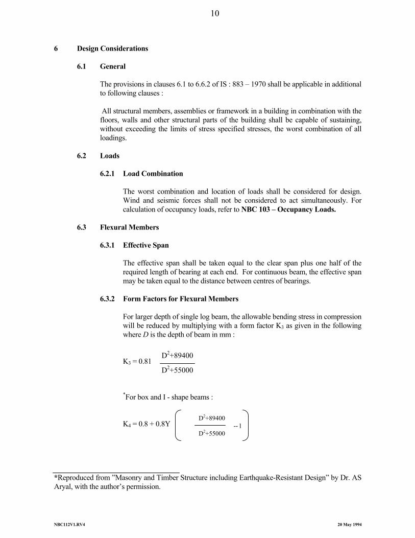
6.3.2 Form Factors for Flexural Members
For larger depth of single log beam, the allowable bending stress in compression will be reduced by multiplying with a form factor K3 as given in the following where D is the depth of beam in mm :
K3 = 0.81
*For box and I - shape beams : K4 = 0.8 + 0.8Y *Reproduced from ”Masonry and Timber Structure including Earthquake-Resistant Design” by Dr. AS Aryal, with the author’s permission.
D2+89400
D2+55000
D2+89400 -- 1
D2+55000
10
NBC112V1.RV4 20 May 1994
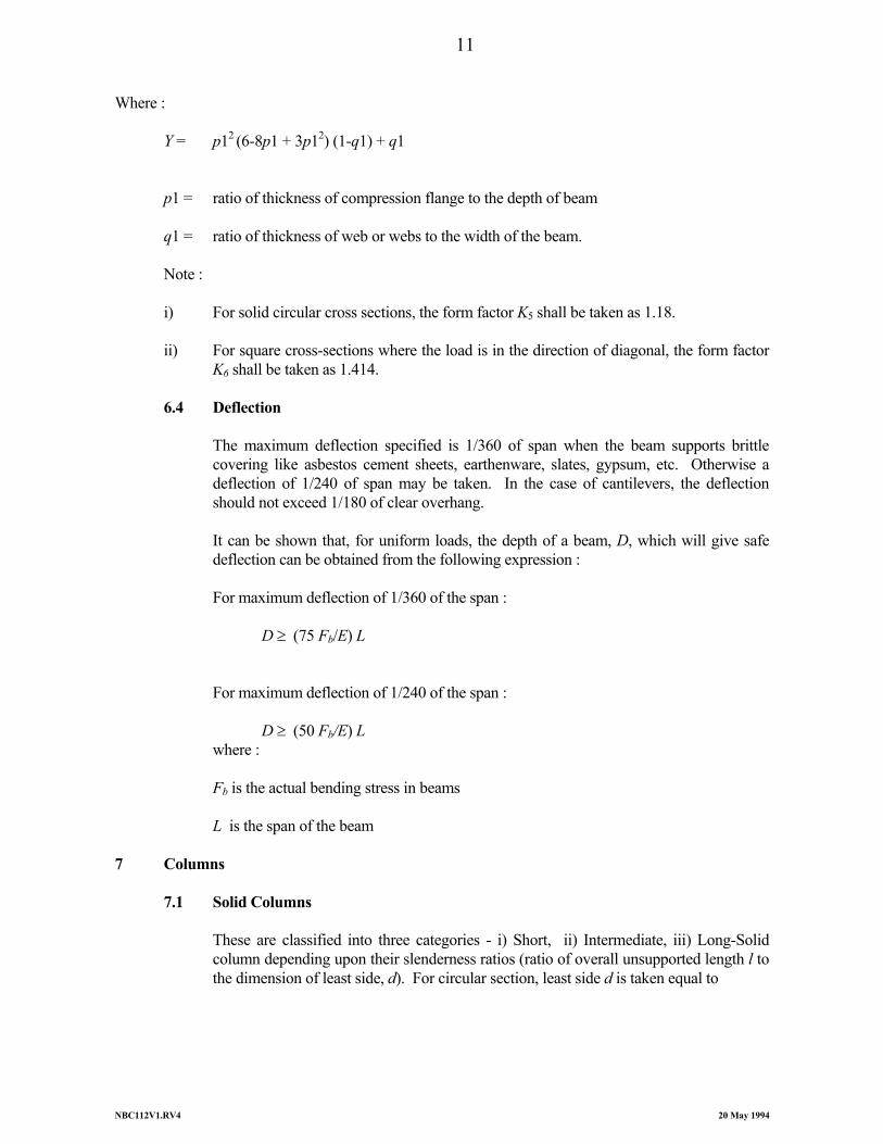
Where : Y = p12 (6-8p1 + 3p12) (1-q1) + q1 p1 = ratio of thickness of compression flange to the depth of beam q1 = ratio of thickness of web or webs to the width of the beam. Note : i) For solid circular cross sections, the form factor K5 shall be taken as 1.18. ii) For square cross-sections where the load is in the direction of diagonal, the form factor
K6 shall be taken as 1.414. 6.4 Deflection
The maximum deflection specified is 1/360 of span when the beam supports brittle covering like asbestos cement sheets, earthenware, slates, gypsum, etc. Otherwise a deflection of 1/240 of span may be taken. In the case of cantilevers, the deflection should not exceed 1/180 of clear overhang.
It can be shown that, for uniform loads, the depth of a beam, D, which will give safe
deflection can be obtained from the following expression : For maximum deflection of 1/360 of the span : D ≥ (75 Fb/E) L For maximum deflection of 1/240 of the span : D ≥ (50 Fb/E) L where : Fb is the actual bending stress in beams L is the span of the beam 7 Columns 7.1 Solid Columns
These are classified into three categories - i) Short, ii) Intermediate, iii) Long-Solid column depending upon their slenderness ratios (ratio of overall unsupported length l to the dimension of least side, d). For circular section, least side d is taken equal to
11
NBC112V1.RV4 20 May 1994
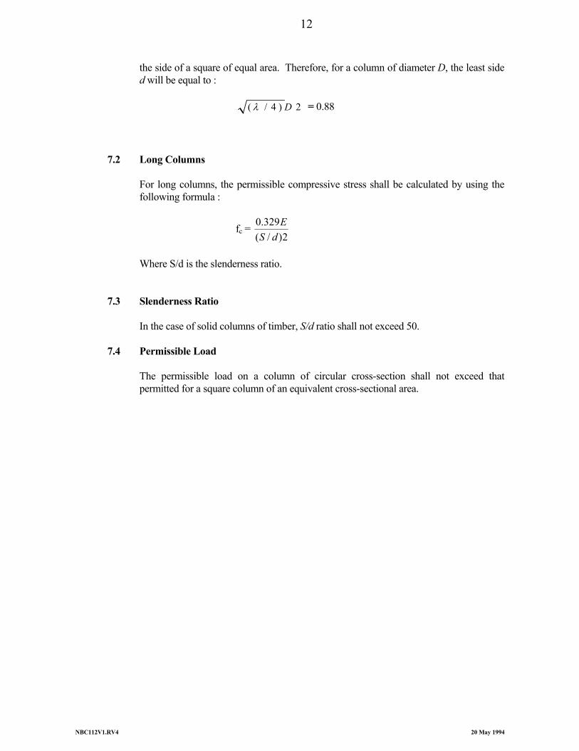
the side of a square of equal area. Therefore, for a column of diameter D, the least side d will be equal to :
2)4/( Dλ = 0.88 7.2 Long Columns
For long columns, the permissible compressive stress shall be calculated by using the following formula :
fc = 2)/(
329.0dS
E
Where S/d is the slenderness ratio. 7.3 Slenderness Ratio In the case of solid columns of timber, S/d ratio shall not exceed 50. 7.4 Permissible Load
The permissible load on a column of circular cross-section shall not exceed that permitted for a square column of an equivalent cross-sectional area.
12
NBC112V1.RV4 20 May 1994
8 Design of Common Steel Wire Nail Joints 8.1 Dimensions of Members
The dimension of an individual piece of timber (that is any single member) shall be within the range given below :
8.1.1 Minimum Thickness
Minimum thickness of any individual member : 30 mm for main members in mono-chord construction; 20 mm for web members and 25 mm for chord members in split-chord construction.
8.1.2 Maximum Thickness
Maximum thickness (other than spacer blocks) : 100 mm. For spacer blocks, not more than three times the thickness of the main elements.
8.1.3 Minimum Depth
Minimum depth of member : 75 mm for chord members and 40 mm for web members of trusses in soft or hard woods.
8.2 Length of Member
Length of members : 4.5 to 5 m maximum in single piece, because longer members are difficult to obtain and are costly.
8.3 Width of Members Width of any individual piece : not to exceed about eight times its thickness. 8.4 Spacing
The space between two adjacent pieces of timber shall be restricted to a maximum of three times the thickness of the individual piece of timber of the chord member. In case of web members, it may be greater for facilities jointing.
8.5 Lengthening Joint
It is preferable that no lengthening-joint shall be located at a panel point. Generally, not more than two, but preferably not more than one, lengthening-joint shall be permitted between the two panel joints of a member.
13
NBC112V1.RV4 20 May 1994
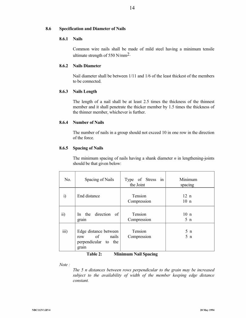
8.6 Specification and Diameter of Nails
8.6.1 Nails Common wire nails shall be made of mild steel having a minimum tensile ultimate strength of 550 N/mm2.
8.6.2 Nails Diameter
Nail diameter shall be between 1/11 and 1/6 of the least thickest of the members to be connected.
8.6.3 Nails Length
The length of a nail shall be at least 2.5 times the thickness of the thinnest member and it shall penetrate the thicker member by 1.5 times the thickness of the thinner member, whichever is further.
8.6.4 Number of Nails
The number of nails in a group should not exceed 10 in one row in the direction of the force.
8.6.5 Spacing of Nails
The minimum spacing of nails having a shank diameter n in lengthening-joints should be that given below:
No.
Spacing of Nails
Type of Stress in the Joint
Minimum spacing
i)
End distance
Tension Compression
12 n 10 n
ii)
In the direction of grain
Tension Compression
10 n 5 n
iii)
Edge distance between row of nails perpendicular to the grain
Tension Compression
5 n 5 n
Table 2: Minimum Nail Spacing
Note : The 5 n distances between rows perpendicular to the grain may be increased subject to the availability of width of the member keeping edge distance constant.
14
NBC112V1.RV4 20 May 1994
9 Design of Bolted Joints
9.1 General
For total prefabrication, bolt-jointed construction most befits structural timber components. Bolt-jointed construction units give better facilities with respect to workshop ease, transport convenience and re-assembly at site of work site. This technique is base-suited for defence purposes for semi-permanent structures (e.g., sheds) which are required to be erected at high altitudes and in remote locations. Mass -production of structural components in factories can thus be made far more rationally.
9.2 Design Considerations
Where a number of bolts are used in a joint, the allowable load in withdrawal or lateral resistance shall be the sum of the allowable loads for the individual bolts.
9.3 Arrangement of Bolts The following spacings in bolted joints shall be followed : a) Spacing of bolts in a row : For loading parallel and perpendicular to grain loading : 4 d3. b) Spacing between rows of bolts : 1) For loading perpendicular to the grain: 2.5 d3 to 5 d3 (2.5 d3 for t/d3 ratio
of 2 and 5 d3 for t/d3 ratio of 6), where t is thickness of main member and d3 is the diameter of the bolt used.
2) For parallel-to-grain loading: At least (N-4) d3, with a minimum of 2.5
d3, where N is total number of bolts. The spacing is also governed by net area at the critical section which should be 80 percent of the total area in bearing under all bolts.
c) Edge Distance :
1) For parallel-to-grain loading 1.5 d3, or half the distance between rows of bolts, whichever is greater.
2) For perpendicular-to-grain loading: the loaded edge distance shall be at
least 4 d3 9.3.1 Spacing
For inclined members, the spacing given above for perpendicular and parallel-to-grain of wood may be used as a guide and bolts arranged at the joint with respect to loading direction.
The bolts shall be arranged in such that the centre of resistance of the bolts passes through the intersection of the centre-of-gravity axes of the members.
15
NBC112V1.RV4 20 May 1994
9.3.2 Staggering
Staggering of bolts shall be avoided as far as possible in the cases where members are loaded parallel to the grain of the wood. For loads acting perpendicular to grain, staggering is preferable in order to avoid splitting due to weather effects.
9.3.3 Bolt Holes
The bolt holes shall be bored or drilled perpendicular to the surface involved. Forcible driving of the bolts shall be avoided which may cause cracking or splitting of members. As a guide, a bolt hole which is 1 mm oversize may be used for pre-boring.
10 Glue Laminated Timber This type of timber is often used for large span structures when both the available cross-sections
and lengths are much limited. The limitation is overcome by building up large size member out of 25 to 50 mm thick planks
by gluing them together so that grain of all planks is in the same direction This operation requires uniform application of glue while maintaining both the required
temperature and applying the necessary pressure. 10.1 Subject to Bending
For best use of laminated timber, high-strength species and select grade timber should use near the extreme fibres of members subject to bending.
Curved members should ordinarily have a minimum radius of curvature of about 130 t
where t is the maximum thickness (in mm) of lamination used.
16
NBC112V1.RV4 20 May 1994
Use Zones
I II III IV
Structural elements Doors and windows
12
10
14
12
17
14
20
16 TABLE 4 : Recommended Percentage Moisture Content Values Note : Zones are defined by annual relative humidities : Zone I less than 40 percent, Zone II 40 to 50 percent, Zone III 50 to 67 percent, and Zone IV more than 67 percent.
Thickness (mm)
Width (mm)
20 25 30 40 50 60 80
100
40 40 40 - - - -
-
50 50 50 - - - -
-
60 60 60 60 60 - -
-
80 80 80 80 80 80 -
-
- 100 100 100 100 100 100
-
- 120 120 120 120 120 120 120
- 140 140 140 140 140 140 140
- 160 160 160 160 160 160 160
TABLE 5 : Preferred Cut Sizes of Structure Timbers for Roof Trusses (from 3 to 20
metres) Note: 2 Preferred lengths of timber : 1 m, 1.5 m, 2 m, 2.5 m and 3 m.
17
NBC112V1.RV4 20 May 1994
Thickness (mm) Width (mm)
60 80 100
80 - -
100 100
-
120 120
-
140 140 140
160 160 160
- -
180
- -
200 TABLE 6 : Preferred Cut Sizes of Structure Timbers for Roof Purlins, Rafters, Floor
Beams, etc. Note : Preferred lengths of timber : 2 m, 2.5 m, 3 m and 3.5 m.
Thickness (mm) Width (mm)
10 15 20 25 30 40 50 60 80
- - - - -
40 - - -
50 50 - - -
50 50 - -
- - - - -
60 60 - -
80 80 80 80 80 80 80 - -
100 100 100 100 100 100 100
- 100
- 120 120 120 120 120 120 120 120
- 160 160 160 160 160 160 160 160
- - -
200 200 200 200 200 200
- - -
240 240 240 240 240 240
Table 7 : Preferred Cut Sizes of Structure Timbers for Partition Framing and
Covering Notes: Preferred lengths of timber : 0.5 m, 1 m, 1.5 m and 2 m.
While nailing, the area of the pre-bored hole shall not be taken into account for this purpose.
18
NBC112V1.RV4 20 May 1994
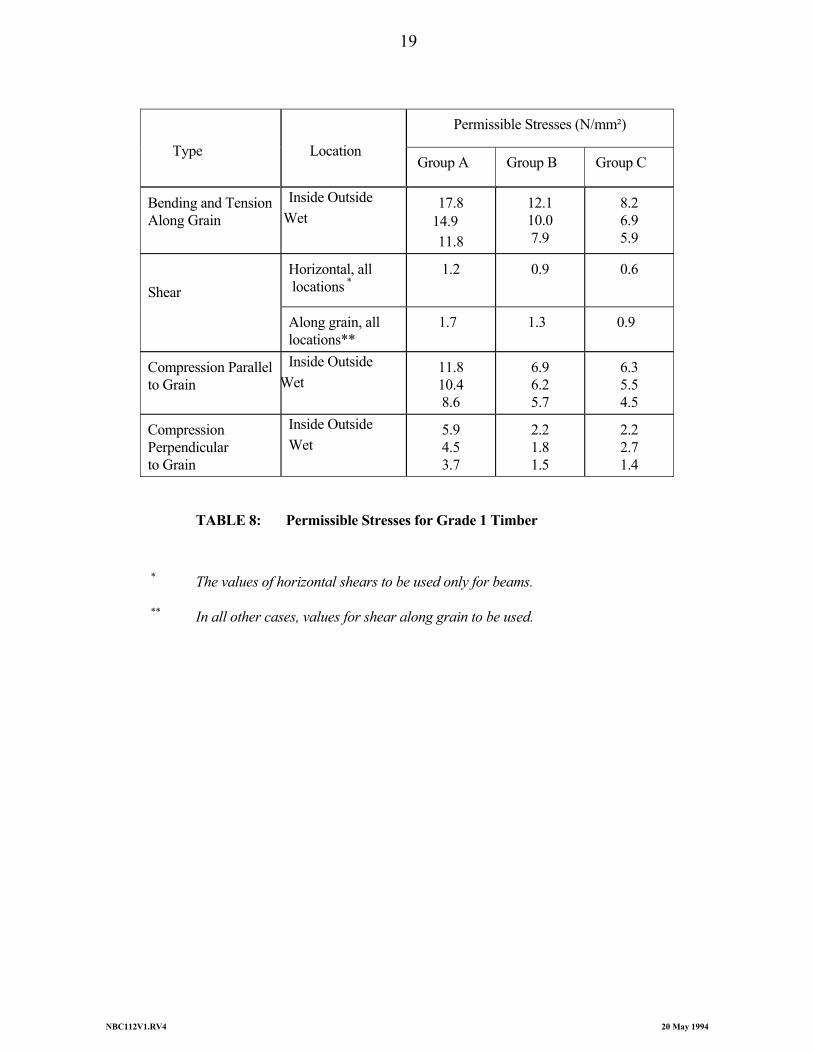
TABLE 8: Permissible Stresses for Grade 1 Timber * The values of horizontal shears to be used only for beams. ** In all other cases, values for shear along grain to be used.
Permissible Stresses (N/mm²)
Type
Location Group A Group B Group C
Bending and Tension Along Grain
Inside Outside Wet
17.8 14.9 11.8
12.1 10.0 7.9
8.2 6.9 5.9
Horizontal, all locations *
1.2 0.9 0.6 Shear
Along grain, all locations**
1.7 1.3 0.9
Compression Parallel to Grain
Inside Outside Wet
11.8 10.4 8.6
6.9 6.2 5.7
6.3 5.5 4.5
Compression Perpendicular to Grain
Inside Outside Wet
5.9 4.5 3.7
2.2 1.8 1.5
2.2 2.7 1.4
19