Embed Size (px)
Citation preview

© 2005 Directed Electronics, Vista, CA N225T 10-05
installation guide3000
®

Bitwriter®, Code Hopping®, Directed®, Doubleguard®, ESP®, FailSafe®, Learn Routine™, Merlin®, Nite-Lite®,Nuisance Prevention®, NPC®, Revenger®, Silent Mode™, Soft Chirp®, Stinger®, Valet®, Vehicle Recovery System™,VRS™, and Warn Away® are all Trademarks or Registered Trademarks of Directed Electronics, Vista, California.
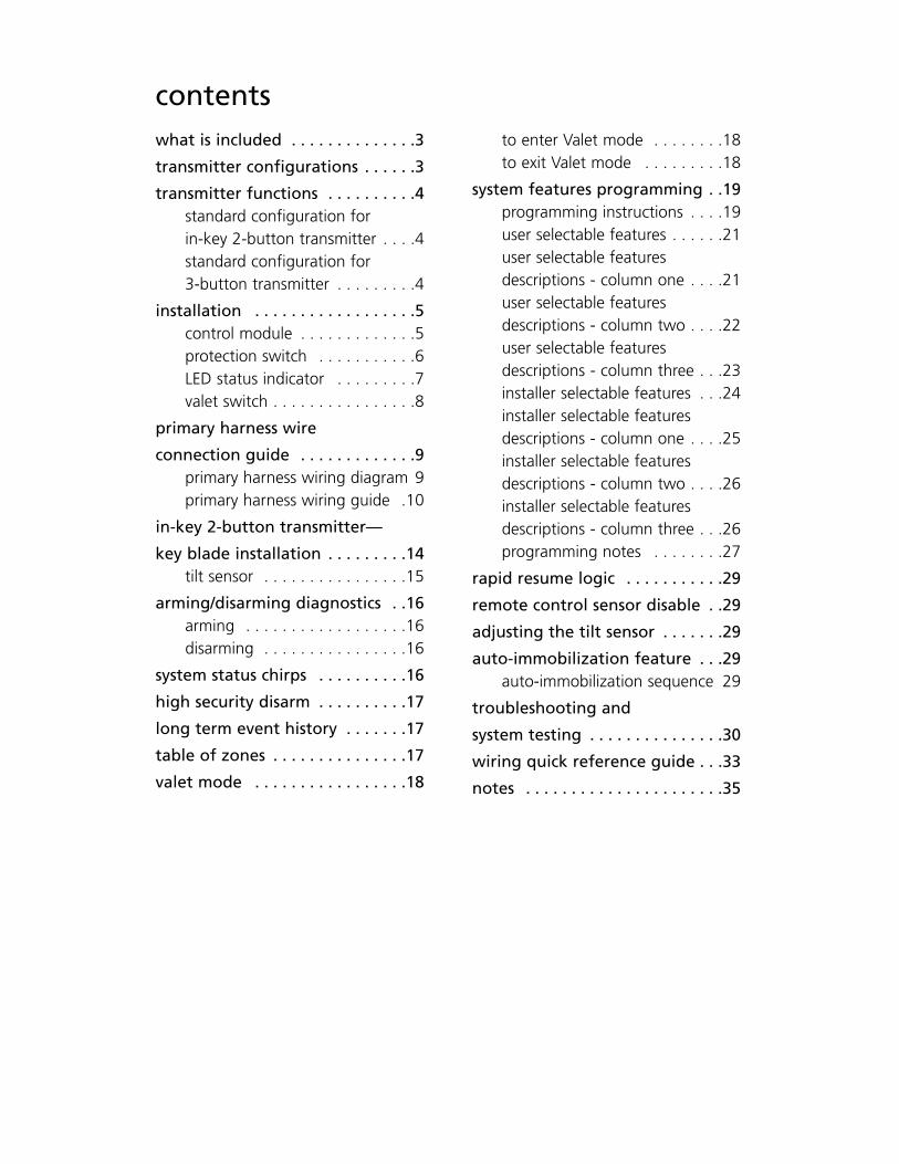
contentswhat is included . . . . . . . . . . . . . .3
transmitter configurations . . . . . .3
transmitter functions . . . . . . . . . .4standard configuration for in-key 2-button transmitter . . . .4standard configuration for 3-button transmitter . . . . . . . . .4
installation . . . . . . . . . . . . . . . . . .5control module . . . . . . . . . . . . .5protection switch . . . . . . . . . . .6LED status indicator . . . . . . . . .7valet switch . . . . . . . . . . . . . . . .8
primary harness wire
connection guide . . . . . . . . . . . . .9primary harness wiring diagram 9primary harness wiring guide .10
in-key 2-button transmitter—
key blade installation . . . . . . . . .14tilt sensor . . . . . . . . . . . . . . . .15
arming/disarming diagnostics . .16arming . . . . . . . . . . . . . . . . . .16disarming . . . . . . . . . . . . . . . .16
system status chirps . . . . . . . . . .16
high security disarm . . . . . . . . . .17
long term event history . . . . . . .17
table of zones . . . . . . . . . . . . . . .17
valet mode . . . . . . . . . . . . . . . . .18
to enter Valet mode . . . . . . . .18to exit Valet mode . . . . . . . . .18
system features programming . .19programming instructions . . . .19user selectable features . . . . . .21user selectable features descriptions - column one . . . .21user selectable features descriptions - column two . . . .22user selectable features descriptions - column three . . .23installer selectable features . . .24installer selectable featuresdescriptions - column one . . . .25installer selectable featuresdescriptions - column two . . . .26installer selectable featuresdescriptions - column three . . .26programming notes . . . . . . . .27
rapid resume logic . . . . . . . . . . .29
remote control sensor disable . .29
adjusting the tilt sensor . . . . . . .29
auto-immobilization feature . . .29auto-immobilization sequence 29
troubleshooting and
system testing . . . . . . . . . . . . . . .30
wiring quick reference guide . . .33
notes . . . . . . . . . . . . . . . . . . . . . .35

© 2005 directed electronics—all rights reserved2
© 2005 directed electronics—all rights reserved 3
what is includedOne control module/siren, with One 3-button transmitterbuilt-in Tilt sensor and 24-pin main wiring harness
One hardware pack Two Merlin decals
One Mini-Blue status LED One Owner’s Guide
One 2-button coded Valet switch Warranty Card
One in-key 2-button transmitter
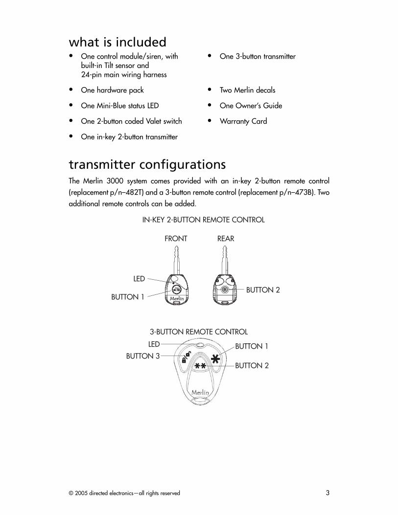
transmitter configurationsThe Merlin 3000 system comes provided with an in-key 2-button remote control(replacement p/n–482T) and a 3-button remote control (replacement p/n–473B). Twoadditional remote controls can be added.
3-BUTTON REMOTE CONTROL
BUTTON 3
LED
BUTTON 2
BUTTON 1
FRONT REAR
LED
BUTTON 1BUTTON 2
IN-KEY 2-BUTTON REMOTE CONTROL
© 2005 directed electronics—all rights reserved4
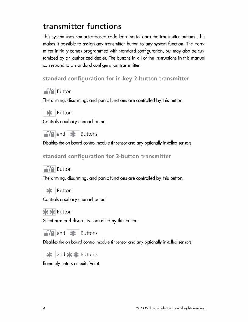
transmitter functionsThis system uses computer-based code learning to learn the transmitter buttons. Thismakes it possible to assign any transmitter button to any system function. The trans-mitter initially comes programmed with standard configuration, but may also be cus-tomized by an authorized dealer. The buttons in all of the instructions in this manualcorrespond to a standard configuration transmitter.
standard configuration for in-key 2-button transmitter
Button
The arming, disarming, and panic functions are controlled by this button.
Button
Controls auxiliary channel output.
and Buttons
Disables the on-board control module tilt sensor and any optionally installed sensors.
standard configuration for 3-button transmitter
Button
The arming, disarming, and panic functions are controlled by this button.
Button
Controls auxiliary channel output.
Button
Silent arm and disarm is controlled by this button.
and Buttons
Disables the on-board control module tilt sensor and any optionally installed sensors.
and Buttons
Remotely enters or exits Valet.
© 2005 directed electronics—all rights reserved 5
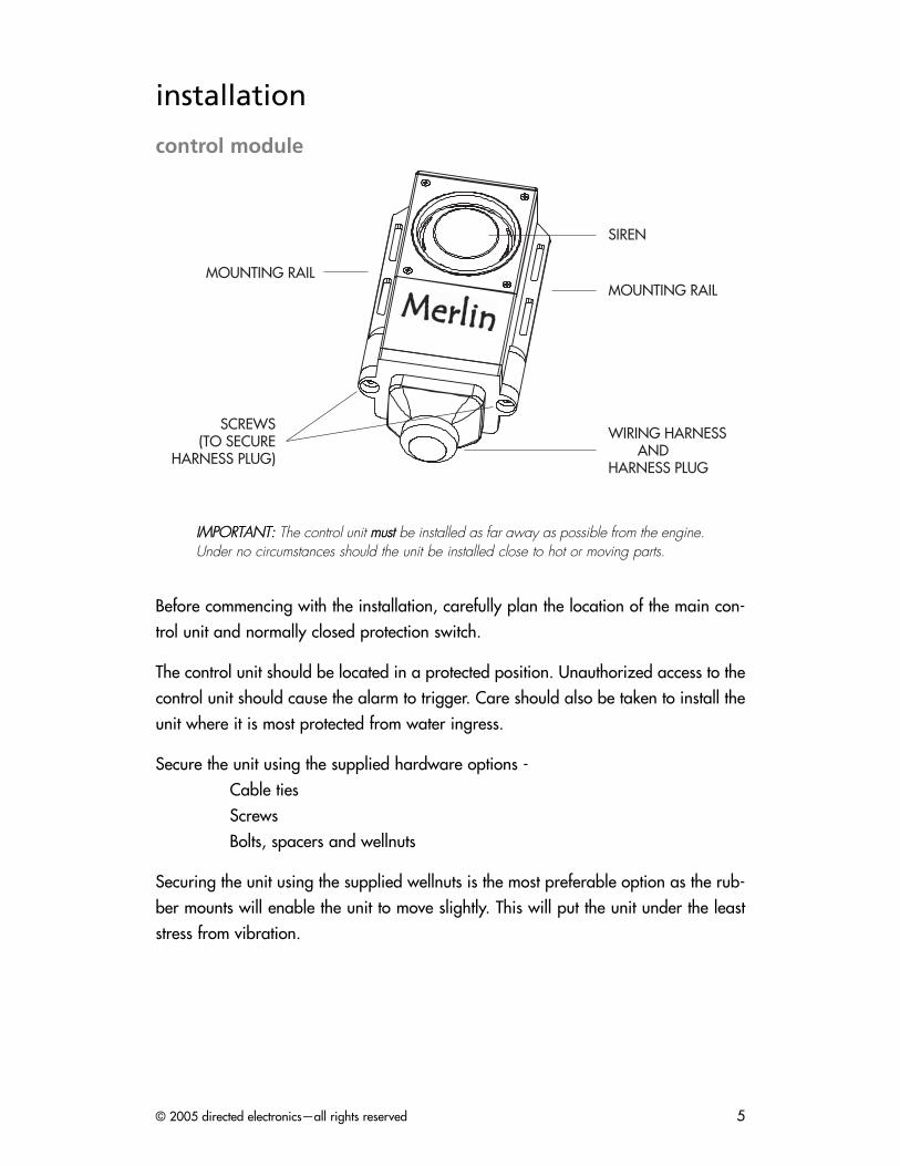
installation
control module
IIMMPPOORRTTAANNTT:: The control unit mmuusstt be installed as far away as possible from the engine.Under no circumstances should the unit be installed close to hot or moving parts.
Before commencing with the installation, carefully plan the location of the main con-trol unit and normally closed protection switch.
The control unit should be located in a protected position. Unauthorized access to thecontrol unit should cause the alarm to trigger. Care should also be taken to install theunit where it is most protected from water ingress.
Secure the unit using the supplied hardware options - Cable tiesScrewsBolts, spacers and wellnuts
Securing the unit using the supplied wellnuts is the most preferable option as the rub-ber mounts will enable the unit to move slightly. This will put the unit under the leaststress from vibration.
SIREN
MOUNTING RAIL
WIRING HARNESS ANDHARNESS PLUG
SCREWS(TO SECURE
HARNESS PLUG)
MOUNTING RAIL
© 2005 directed electronics—all rights reserved6
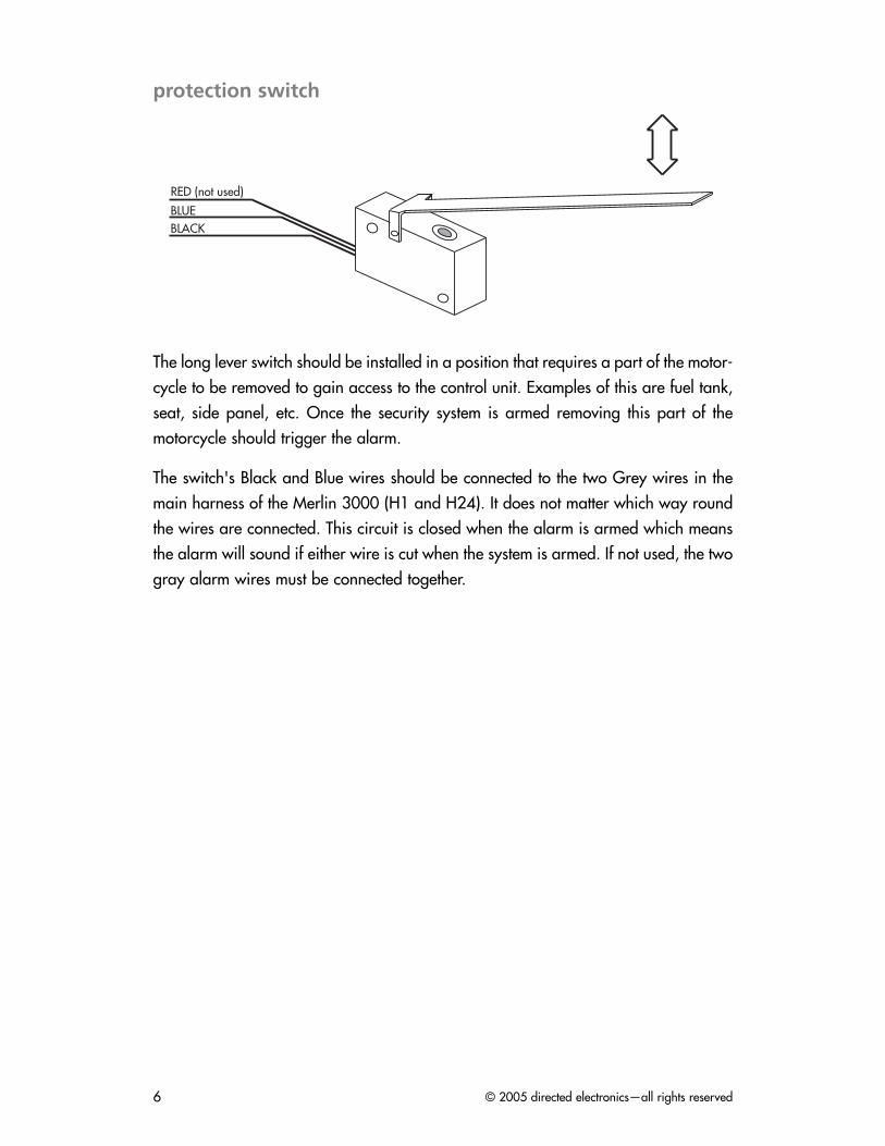
protection switch
The long lever switch should be installed in a position that requires a part of the motor-cycle to be removed to gain access to the control unit. Examples of this are fuel tank,seat, side panel, etc. Once the security system is armed removing this part of themotorcycle should trigger the alarm.
The switch's Black and Blue wires should be connected to the two Grey wires in themain harness of the Merlin 3000 (H1 and H24). It does not matter which way roundthe wires are connected. This circuit is closed when the alarm is armed which meansthe alarm will sound if either wire is cut when the system is armed. If not used, the twogray alarm wires must be connected together.
RED (not used)
BLACKBLUE
© 2005 directed electronics—all rights reserved 7
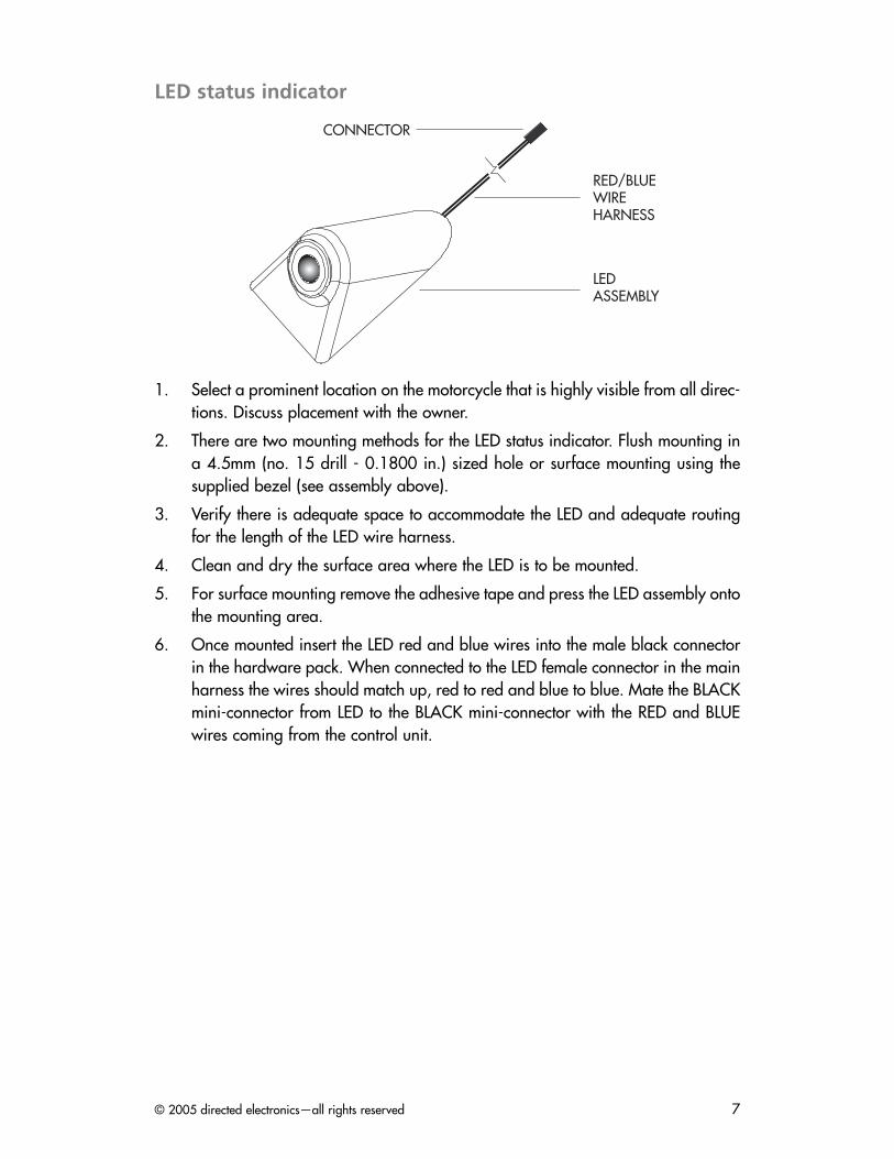
LED status indicator
1. Select a prominent location on the motorcycle that is highly visible from all direc-tions. Discuss placement with the owner.
2. There are two mounting methods for the LED status indicator. Flush mounting ina 4.5mm (no. 15 drill - 0.1800 in.) sized hole or surface mounting using thesupplied bezel (see assembly above).
3. Verify there is adequate space to accommodate the LED and adequate routingfor the length of the LED wire harness.
4. Clean and dry the surface area where the LED is to be mounted.
5. For surface mounting remove the adhesive tape and press the LED assembly ontothe mounting area.
6. Once mounted insert the LED red and blue wires into the male black connectorin the hardware pack. When connected to the LED female connector in the mainharness the wires should match up, red to red and blue to blue. Mate the BLACKmini-connector from LED to the BLACK mini-connector with the RED and BLUEwires coming from the control unit.
RED/BLUEWIRE HARNESS
LEDASSEMBLY
CONNECTOR
© 2005 directed electronics—all rights reserved8
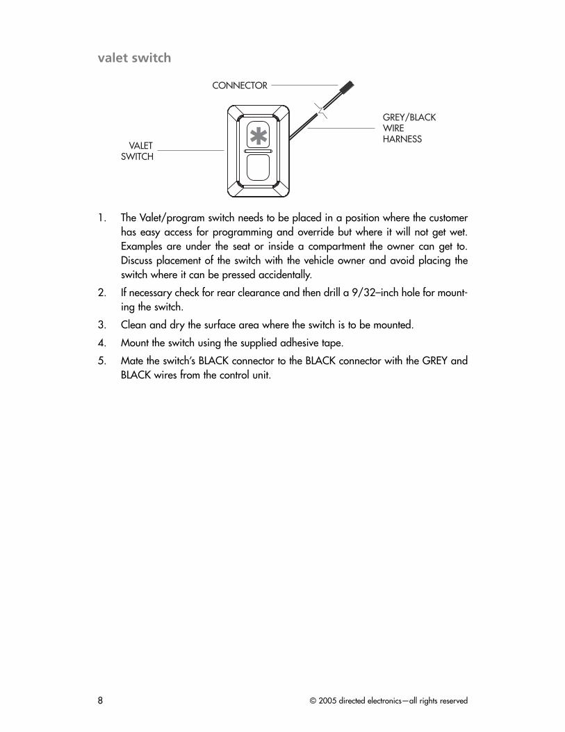
valet switch
1. The Valet/program switch needs to be placed in a position where the customerhas easy access for programming and override but where it will not get wet.Examples are under the seat or inside a compartment the owner can get to.Discuss placement of the switch with the vehicle owner and avoid placing theswitch where it can be pressed accidentally.
2. If necessary check for rear clearance and then drill a 9/32–inch hole for mount-ing the switch.
3. Clean and dry the surface area where the switch is to be mounted.
4. Mount the switch using the supplied adhesive tape.
5. Mate the switch’s BLACK connector to the BLACK connector with the GREY andBLACK wires from the control unit.
GREY/BLACKWIRE HARNESS
CONNECTOR
VALETSWITCH
© 2005 directed electronics—all rights reserved 9
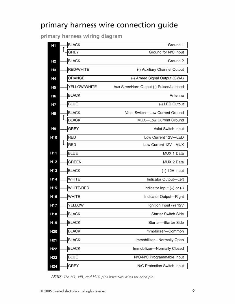
primary harness wire connection guideprimary harness wiring diagram
___[_
___
___
___
___
___
___
___[_
___
___[_
___
___
___
___
___
___
___
___
___
___
___
___
___
___
NNOOTTEE:: The H1, H8, and H10 pins have two wires for each pin.
GREY N/C Protection Switch Input
BLUE N/O-N/C Programmable Input
BLACK Immobilizer—Normally Closed
BLACK Immobilizer—Normally Open
BLACK Immobilizer—Common
BLACK Starter—Starter Side
BLACK Starter Switch Side
YELLOW Ignition Input (+) 12V
WHITE Indicator Output—Right
WHITE/RED Indicator Input (+) or (-)
WHITE Indicator Output—Left
BLACK (+) 12V Input
GREEN MUX 2 Data
BLUE MUX 1 Data
RED Low Current 12V—MUX
RED Low Current 12V—LED
GREY Valet Switch Input
BLACK MUX—Low Current Ground
BLACK Valet Switch—Low Current Ground
BLUE (-) LED Output
BLACK Antenna
YELLOW/WHITE Aux Siren/Horn Output (-) Pulsed/Latched
ORANGE (-) Armed Signal Output (GWA)
RED/WHITE (-) Auxiliary Channel Output
BLACK Ground 2
GREY Ground for N/C input
BLACK Ground 1H1
H2
H3
H4
H5
H6
H7
H8
H9
H10
H11
H12
H13
H14
H15
H16
H17
H18
H19
H20
H21
H22
H23
H24
© 2005 directed electronics—all rights reserved10
The BLACK wires in the harness are identified with labels describing their function (seetable below). These labels are to be removed after installation.
primary harness wiring guide
This guide describes in detail the connection of each wire. Also included are possible appli-cations of each wire. This system was designed with the ultimate in flexibility and securityin mind. Many of the wires have more than one possible function. Please read the instruc-tions carefully to ensure a thorough understanding of this unit and how it operates.
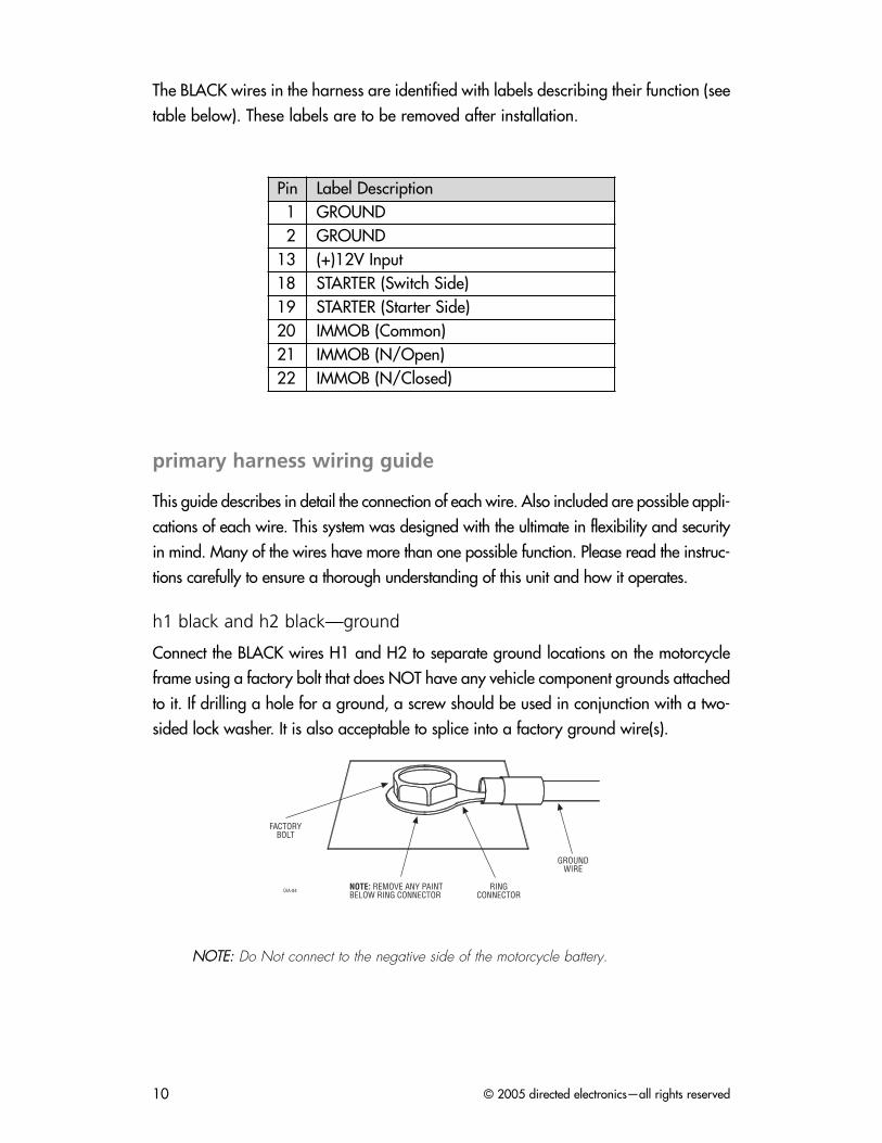
h1 black and h2 black—ground
Connect the BLACK wires H1 and H2 to separate ground locations on the motorcycleframe using a factory bolt that does NOT have any vehicle component grounds attachedto it. If drilling a hole for a ground, a screw should be used in conjunction with a two-sided lock washer. It is also acceptable to splice into a factory ground wire(s).
NNOOTTEE:: Do Not connect to the negative side of the motorcycle battery.
Pin Label Description1 GROUND2 GROUND
13 (+)12V Input18 STARTER (Switch Side)19 STARTER (Starter Side)20 IMMOB (Common)21 IMMOB (N/Open)22 IMMOB (N/Closed)
© 2005 directed electronics—all rights reserved 11
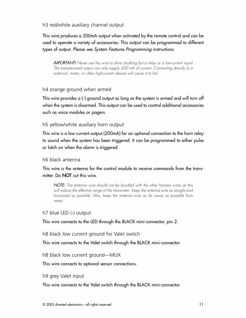
h3 red/white auxiliary channel output
This wire produces a 200mA output when activated by the remote control and can beused to operate a variety of accessories. This output can be programmed to differenttypes of output. Please see System Features Programming instructions
IIMMPPOORRTTAANNTT!! Never use this wire to drive anything but a relay or a low-current input!The transistorized output can only supply 200 mA of current. Connecting directly to asolenoid, motor, or other high-current device will cause it to fail.
h4 orange ground when armed
This wire provides a (-) ground output as long as the system is armed and will turn offwhen the system is disarmed. This output can be used to control additional accessoriessuch as voice modules or pagers.
h5 yellow/white auxiliary horn output
This wire is a low current output (200mA) for an optional connection to the horn relayto sound when the system has been triggered. It can be programmed to either pulseor latch on when the alarm is triggered.
h6 black antenna
This wire is the antenna for the control module to receive commands from the trans-mitter. Do NNOOTT cut this wire.
NNOOTTEE:: The antenna wire should not be bundled with the other harness wires as thiswill reduce the effective range of the transmitter. Keep the antenna wire as straight andhorizontal as possible. Also, keep the antenna wire as far away as possible frommetal.
h7 blue LED (-) output
This wire connects to the LED through the BLACK mini-connector, pin 2.
h8 black low current ground for Valet switch
This wire connects to the Valet switch through the BLACK mini-connector.
h8 black low current ground—MUX
This wire connects to optional sensor connections.
h9 grey Valet input
This wire connects to the Valet switch through the BLACK mini-connector.
© 2005 directed electronics—all rights reserved12
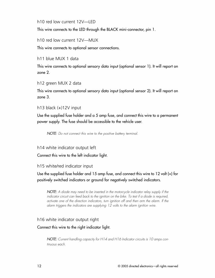
h10 red low current 12V—LED
This wire connects to the LED through the BLACK mini-connector, pin 1.
h10 red low current 12V—MUX
This wire connects to optional sensor connections.
h11 blue MUX 1 data
This wire connects to optional sensory data input (optional sensor 1). It will report onzone 2.
h12 green MUX 2 data
This wire connects to optional sensory data input (optional sensor 2). It will report onzone 3.
h13 black (+)12V input
Use the supplied fuse holder and a 5 amp fuse, and connect this wire to a permanentpower supply. The fuse should be accessible to the vehicle user.
NNOOTTEE:: Do not connect this wire to the positive battery terminal.
h14 white indicator output left
Connect this wire to the left indicator light.
h15 white/red indicator input
Use the supplied fuse holder and 15 amp fuse, and connect this wire to 12 volt (+) forpositively switched indicators or ground for negatively switched indicators.
NNOOTTEE:: A diode may need to be inserted in the motorcycle indicator relay supply if theindicator circuit can feed back to the ignition on the bike. To test if a diode is required,activate one of the direction indicators, turn ignition off and then arm the alarm. If thealarm triggers the indicators are supplying 12 volts to the alarm ignition wire.
h16 white indicator output right
Connect this wire to the right indicator light.
NNOOTTEE:: Current handling capacity for H14 and H16 Indicator circuits is 10 amps con-tinuous each.
© 2005 directed electronics—all rights reserved 13
h17 yellow ignition input (+)12 V
Connect this wire to any ignition wire on the motorcycle that remains positive whilethe starter button is pressed. It will report on zone 6 if triggered when armed.
h18 black starter (switch side)
Connect this wire to the starter input side from the starter switch.
h19 black starter (starter side)
Connect this wire to the starter side.
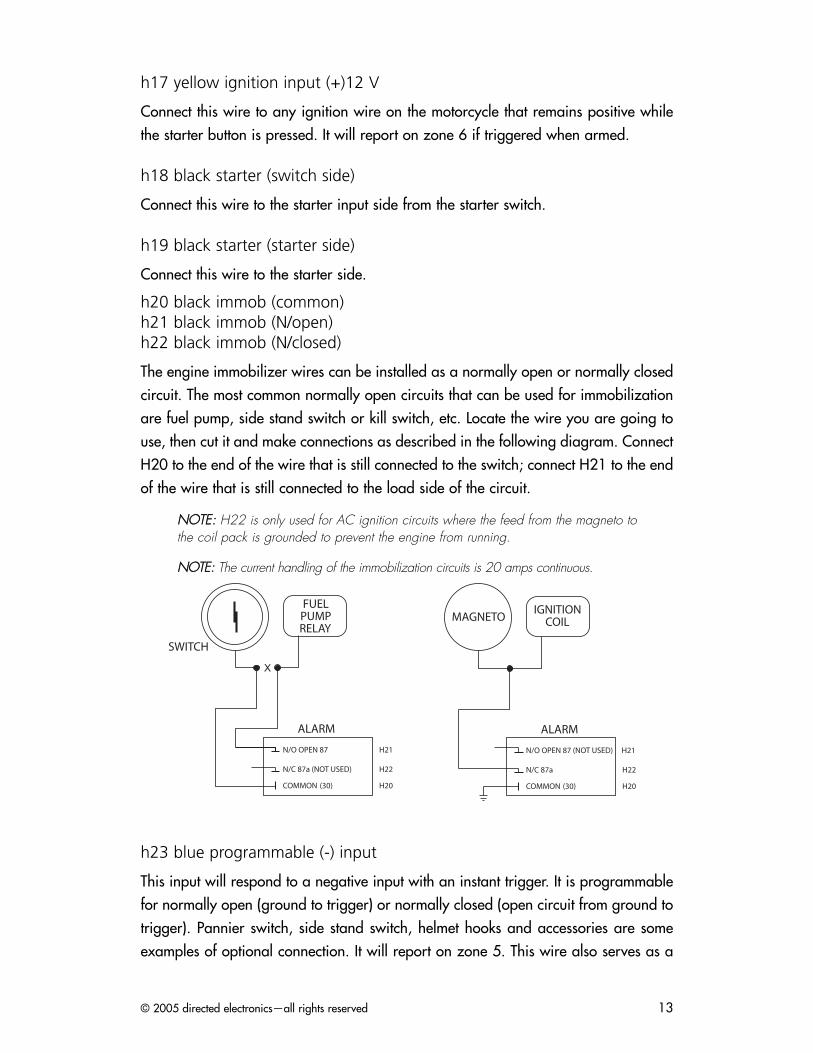
h20 black immob (common)h21 black immob (N/open)h22 black immob (N/closed)
The engine immobilizer wires can be installed as a normally open or normally closedcircuit. The most common normally open circuits that can be used for immobilizationare fuel pump, side stand switch or kill switch, etc. Locate the wire you are going touse, then cut it and make connections as described in the following diagram. ConnectH20 to the end of the wire that is still connected to the switch; connect H21 to the endof the wire that is still connected to the load side of the circuit.
NNOOTTEE:: H22 is only used for AC ignition circuits where the feed from the magneto tothe coil pack is grounded to prevent the engine from running.
NNOOTTEE:: The current handling of the immobilization circuits is 20 amps continuous.
h23 blue programmable (-) input
This input will respond to a negative input with an instant trigger. It is programmablefor normally open (ground to trigger) or normally closed (open circuit from ground totrigger). Pannier switch, side stand switch, helmet hooks and accessories are someexamples of optional connection. It will report on zone 5. This wire also serves as a
IGNITIONCOIL
ALARM
N/O OPEN 87 (NOT USED) H21
N/C 87a H22
COMMON (30) H20
MAGNETOFUELPUMPRELAY
ALARM
N/O OPEN 87 H21
N/C 87a (NOT USED) H22
COMMON (30) H20
SWITCH
© 2005 directed electronics—all rights reserved14
remote start shunt input when ground is applied during remote start and aux outputis programmed to remote start.
h1 and h24 grey twin bonded harness
Connect to the blue and black wires of the long lever protection switch. It will reporton zone 4.
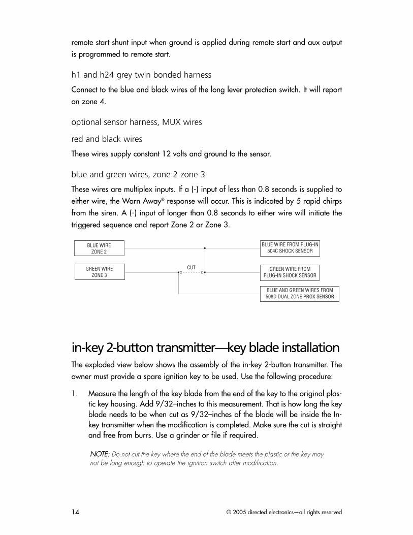
optional sensor harness, MUX wires
red and black wires
These wires supply constant 12 volts and ground to the sensor.
blue and green wires, zone 2 zone 3
These wires are multiplex inputs. If a (-) input of less than 0.8 seconds is supplied toeither wire, the Warn Away® response will occur. This is indicated by 5 rapid chirpsfrom the siren. A (-) input of longer than 0.8 seconds to either wire will initiate thetriggered sequence and report Zone 2 or Zone 3.
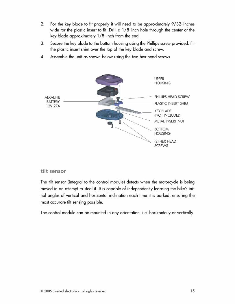
in-key 2-button transmitter—key blade installationThe exploded view below shows the assembly of the in-key 2-button transmitter. Theowner must provide a spare ignition key to be used. Use the following procedure:
1. Measure the length of the key blade from the end of the key to the original plas-tic key housing. Add 9/32–inches to this measurement. That is how long the keyblade needs to be when cut as 9/32–inches of the blade will be inside the In-key transmitter when the modification is completed. Make sure the cut is straightand free from burrs. Use a grinder or file if required.
NNOOTTEE:: Do not cut the key where the end of the blade meets the plastic or the key maynot be long enough to operate the ignition switch after modification.
�������������
�������������
����������������� ������������������
��������� ������������������������������������
���������������� ��������������
� ����
© 2005 directed electronics—all rights reserved 15
2. For the key blade to fit properly it will need to be approximately 9/32–incheswide for the plastic insert to fit. Drill a 1/8–inch hole through the center of thekey blade approximately 1/8–inch from the end.
3. Secure the key blade to the bottom housing using the Phillips screw provided. Fitthe plastic insert shim over the top of the key blade and screw.
4. Assemble the unit as shown below using the two hex-head screws.
tilt sensor
The tilt sensor (integral to the control module) detects when the motorcycle is beingmoved in an attempt to steal it. It is capable of independently learning the bike’s ini-tial angles of vertical and horizontal inclination each time it is parked, ensuring themost accurate tilt sensing possible.
The control module can be mounted in any orientation. i.e. horizontally or vertically.
KEY BLADE(NOT INCLUDED)
PLASTIC INSERT SHIM
METAL INSERT NUT
UPPERHOUSING
BOTTOMHOUSING
(2) HEX HEADSCREWS
ALKALINEBATTERY12V 27A
PHILLIPS HEAD SCREW
© 2005 directed electronics—all rights reserved16
arming/disarming diagnosticsThe systems microprocessor monitors and reports all active and violated zones whenarming and disarming the system.
arming
Zones that are active at the time the system is armed are reported by a single status chirpcalled Malfunction AutoBypass. The specific zone bypassed is then reported by the LED.For more zone information, refer to Table of Zones section of this guide.
You are able to see exactly which zone is causing the bypass notification by disarmingthe system and turning the ignition on. The zone will be reported by flashing the activezone 5 times.
disarming
If a zone has been triggered, four disarm chirps will sound. The specific zone that wastriggered is then reported by the LED when the ignition is turned on. For more zoneinformation, refer to the Table of Zones section of this guide.
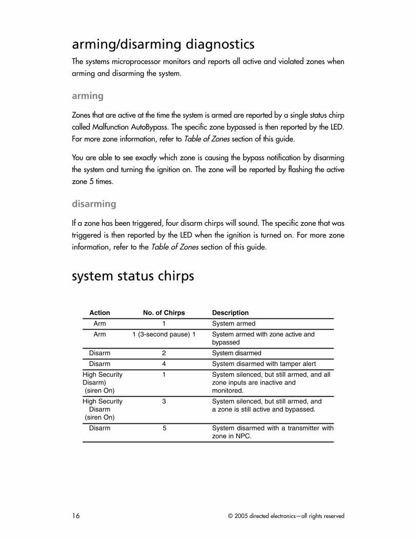
system status chirps
Action No. of Chirps Description
Arm 1 System armed
Arm 1 (3-second pause) 1 System armed with zone active and bypassed
Disarm 2 System disarmed
Disarm 4 System disarmed with tamper alert
High Security 1 System silenced, but still armed, and allDisarm) zone inputs are inactive and (siren On) monitored.
High Security 3 System silenced, but still armed, and Disarm a zone is still active and bypassed.
(siren On)
Disarm 5 System disarmed with a transmitter with zone in NPC.
© 2005 directed electronics—all rights reserved 17
high security disarmWhile the siren is sounding, press the arm/disarm button once to silence the siren butleave the system in the armed state. To disarm the system, press the arm/disarm but-ton a second time.
long term event historyThis will report the last eight system triggers in reverse chronological order.
1. Press and hold of the Valet switch.
2. While still holding , arm and disarm the system, then release the button.
3. The LED will start to flash to indicate the most recent trigger and proceed down tothe eighth trigger. For more information, please refer to the Table of Zones sectionof this guide.
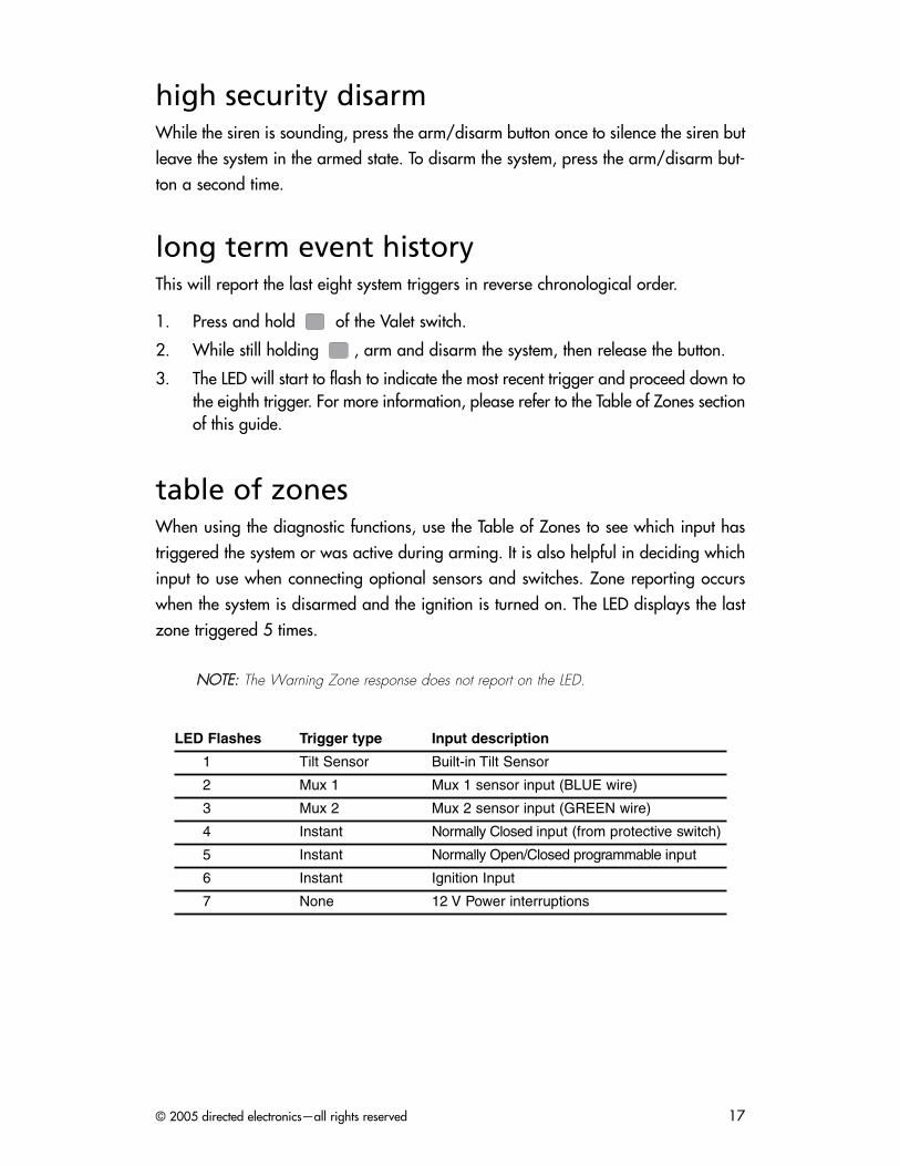
table of zonesWhen using the diagnostic functions, use the Table of Zones to see which input hastriggered the system or was active during arming. It is also helpful in deciding whichinput to use when connecting optional sensors and switches. Zone reporting occurswhen the system is disarmed and the ignition is turned on. The LED displays the lastzone triggered 5 times.
NNOOTTEE:: The Warning Zone response does not report on the LED.
LED Flashes Trigger type Input description
1 Tilt Sensor Built-in Tilt Sensor
2 Mux 1 Mux 1 sensor input (BLUE wire)
3 Mux 2 Mux 2 sensor input (GREEN wire)
4 Instant Normally Closed input (from protective switch)
5 Instant Normally Open/Closed programmable input
6 Instant Ignition Input
7 None 12 V Power interruptions
© 2005 directed electronics—all rights reserved18
valet modePrevents the security system from automatically arming. In Valet Mode, the securitysystem will not arm, even with the remote, but any accessory functions will continueto work normally.
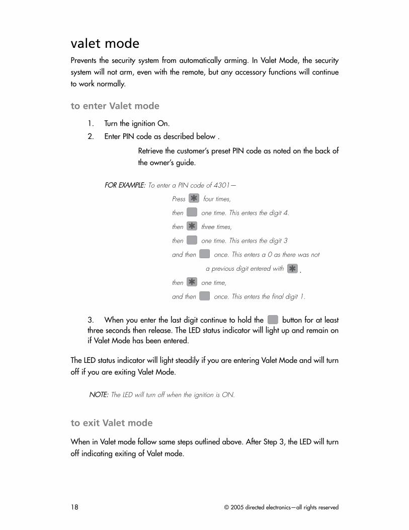
to enter Valet mode
1. Turn the ignition On.
2. Enter PIN code as described below .
Retrieve the customer’s preset PIN code as noted on the back ofthe owner’s guide.
FFOORR EEXXAAMMPPLLEE:: To enter a PIN code of 4301—
Press four times,
then one time. This enters the digit 4.
then three times,
then one time. This enters the digit 3
and then once. This enters a 0 as there was not
a previous digit entered with .
then one time,
and then once. This enters the final digit 1.
3. When you enter the last digit continue to hold the button for at leastthree seconds then release. The LED status indicator will light up and remain onif Valet Mode has been entered.
The LED status indicator will light steadily if you are entering Valet Mode and will turnoff if you are exiting Valet Mode.
NNOOTTEE:: The LED will turn off when the ignition is ON.
to exit Valet mode
When in Valet mode follow same steps outlined above. After Step 3, the LED will turnoff indicating exiting of Valet mode.
© 2005 directed electronics—all rights reserved 19
system features programmingThis system has many features that can be programmed to accommodate the user'spersonal preferences and make system installation easier. They are listed in two pro-gramming grids on the following pages. Many features have default settings that havebeen programmed at the factory and are indicated in bold type.
The User Selectable Features grid allows the user and installer to change operationalfeatures through the Valet switch. The Installer Selectable Features grid allows theinstaller to change input/output functions of the system to integrate with the motorcy-cle’s specific characteristics.
programming instructions
It is a good idea to document changes by taking notes of all feature changes made inprogramming mode.
To enter the User Selectable Features programming:
1. Ignition on - Turn the ignition to the run position or start the engine.
2. Enter PIN - Refer to the previous discussion in the Valet Mode section.
3. Hold/Chirp/Release (User Selectable Features) - After entering the PIN code,press and hold until a chirp is heard and the LED turns on, then release thebutton. You have now entered the feature selection position of the UserSelectable Features grid.
4. Continue Hold (Installer Selectable Features) - Continue to hold the buttonafter the first chirp is heard for another 10-seconds, until the unit chirps 3-times.Release the button.
5. Column select - Press the same number of times as the desired column. Aftera pause the siren will chirp the same number of times as the selected column forconfirmation (e.g. 3-chirps means column 3 of the features is selected).
6. Feature select - Press the same number of times as the desired feature. Thesiren will chirp with each press. The feature can now be changed using theremote control.
7. Feature change - Press the button on the transmitter. If the system chirpsonce, the feature has just turned off or switched to the first setting in the grid slotfor this feature.; if the system chips twice, the feature has just turned on orswitched to the second setting in the grid slot.
© 2005 directed electronics—all rights reserved20
If the feature has more than two settings, continue pressing the arm/disarm but-ton on the transmitter to toggle through the settings (e.g. if the feature has 1through 5 settings, the system will chirp 1 through 5 times for each setting select-ed). If you continue to press and release the transmitter the feature setting willwrap back around to the first setting again. (e.g. if the feature has 3 settings youwill hear, 1 chirp, 2, chirps, 3 chirps, 1 chirp, 2 chirps, etc).
To advance to another feature in the same column, press the same numberof times as the desired feature within 60 seconds; to change a feature in adifferent column begin at step 5 by entering the column number first and thenthe feature select in step 6.
NNOOTTEE:: Refer to the Feature Descriptions sections of this guide for important notes anddescriptions of the system features and programming.
8. Grid Jump - To change a feature in a different feature grid - Press and hold thebutton for 10 seconds and you will jump from one grid to another. (e.g. You
are in the user programming grid and would like to jump to the installer grid.Press and hold for 10 seconds, you will hear 3 chirps indicating installergrid entry. Now program the features by entering the columns and rows asdescribed previously.) 3 chirps are always heard when entering installer pro-gramming grid and 1 chirp when entering user programming grid.
9. Exit programming - To exit programming mode turn the ignition off or wait 60seconds without pressing the Valet switch. The siren will chirp three times to indi-cate programming mode has been exited.
NNOOTTEE:: After you change a feature setting, the feature counter is reset to zero. Hence,to change another feature in the same column you must press the button the samenumber of times as indicated in the chart below.
© 2005 directed electronics—all rights reserved 21
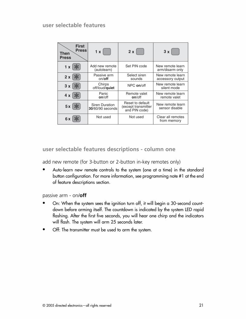
user selectable features
user selectable features descriptions - column one
add new remote (for 3-button or 2-button in-key remotes only)
Auto-learn new remote controls to the system (one at a time) in the standardbutton configuration. For more information, see programming note #1 at the endof feature descriptions section.
passive arm - on/off
On: When the system sees the ignition turn off, it will begin a 30-second count-down before arming itself. The countdown is indicated by the system LED rapidflashing. After the first five seconds, you will hear one chirp and the indicatorswill flash. The system will arm 25 seconds later.
Off: The transmitter must be used to arm the system.
����������
�������
�������������� ������
���������� ����������������������������
����������������
������������ ���
����������������������� �
���������� �� ����
�������� �����������������������
���������
�������������
�����������������������
������� ������� !�"!�������
���������� ���#������������������������
������������������������$��
�� ��� ������������������������
�� ���
© 2005 directed electronics—all rights reserved22
chirps - off/loud/quiet
Off: Chirps will not sound when arming/disarming the system (with the excep-tion of arm/disarm diagnostic chirps and programming chirps).
Loud: Chirps will sound when arming/disarming the system at full volume.
Quiet: Chirps will sound when arming/disarming the system but at a lowervolume than normal.
panic - on/off
Allows the remote to activate Panic Mode. The siren will sound for 30 seconds.
On: The system will enter Panic Mode if the arm/disarm button is pressed formore than 2 seconds.
Off: Panic Mode is disabled.
siren duration - 30/60/90
The system will sound the alarm for the programmed duration (30/60/90 sec-onds) during an alarm trigger or when the system is put into panic mode.
user selectable features descriptions - column two
change valet/pin code
This feature allows you to change the user's personal PIN code. For more infor-mation, see programming note #3.
select siren sounds
This feature allows you to select which siren sounds will be played back when thealarm is triggered. Use the following procedure to set this feature:
1. Enter the feature.
2. Press the button of the remote to begin the playing of siren sounds.
3. Siren will generate each sound for 5-seconds.
4. To add the sound press the button on the Valet switch while that sound isplaying.
5. To delete the sound press the button on the Valet switch while that sound isplaying.
NNOOTTEE:: After selecting or deleting a sound the siren will immediately play the nextsound. If no sounds are selected by pressing the or button the system willremain in its previous setting.

© 2005 directed electronics—all rights reserved 23
npc on/off
Nuisance Prevention® Circuitry (NPC®) stops repeated triggering of the same zone. Ifone zone is triggered three times in one hour, that zone is bypassed for one hour,starting from the time of the third trigger. During that hour, if the system detects a trig-ger on that zone again, the system resets the one hour timer. If one hour passes andthe zone has not triggered again, the zone is activated and can trigger the systemagain. NPC® monitors sensor inputs and the door trigger, but does not bypass theignition trigger at any time. If NPC® is turned off, the system will respond to repeatedtriggers on the sensor inputs and will do so indefinitely. Some states have laws regu-lating how many times a security system can trigger before it is considered a nuisanceand the vehicle is towed away.
remote valet - on/off
On: The alarm can be put into Valet mode with the remote control.
Off: The alarm cannot be put into Valet mode with the remote control.
reset all features to factory settings
All system settings (except PIN and remote programming) in the UserProgramming grid will be reset to their default factory setting as indicated inbold lettering. No installer programmable features will be changed. The MultipleEvent Total recall memory is also cleared.
Press the arm/disarm button of the TX; the siren will chirp twice as confirmation.
user selectable features descriptions - column three
The features in this column pertain to programming individual transmitter channels incustom configurations. Following is an explanation of the features. Program the indi-vidual transmitter channels, referring to note #2 in the Programming Notes section.
arm/disarm only
The remote control channel programmed into this feature will arm/disarm thesystem only.
NNOOTTEE:: When programming a new remote control to custom configuration a channelmust first be programmed to this feature before programming the remaining channels.
accessory (-) output
The transmitter channel programmed into this feature will activate the accessoryoutput.
© 2005 directed electronics—all rights reserved24
silent mode
The transmitter channel programmed into this feature will arm/disarm thesystem, but the siren will not chirp.
remote valet
The transmitter channel programmed into this feature will make the systementer/exit Valet mode.
sensor disable
The transmitter channel programmed for this feature will make the system bypassthe sensors for one arming cycle only. On the next arming cycle, zones 1, 2, and3 will be active.
clear all remotes
This feature will erase all remote codes from the system memory. This feature isconvenient for erasing any transmitters that have been lost, stolen, or incorrect-ly programmed into the system.
After entering this feature press the button on a transmitter that isprogrammed to the system; the siren will chirp twice to indicate that all trans-mitters have been erased from memory.
installer selectable features
To enter the Installer Selectable Features grid follow the instructions for the UserSelectable Features with the exception of step 3. Perform step 3 as described belowto enter the Installer Selectable Features grid.
Hold/Chirp/Release - After entering the PIN code, press and hold until the sirenchirps once. Continue holding for approximately 10 seconds until the siren chirpsthree times, then release the button. You have now entered the feature selection posi-tion of the Installer Selectable Features grid.
© 2005 directed electronics—all rights reserved 25
installer selectable features descriptions - column one
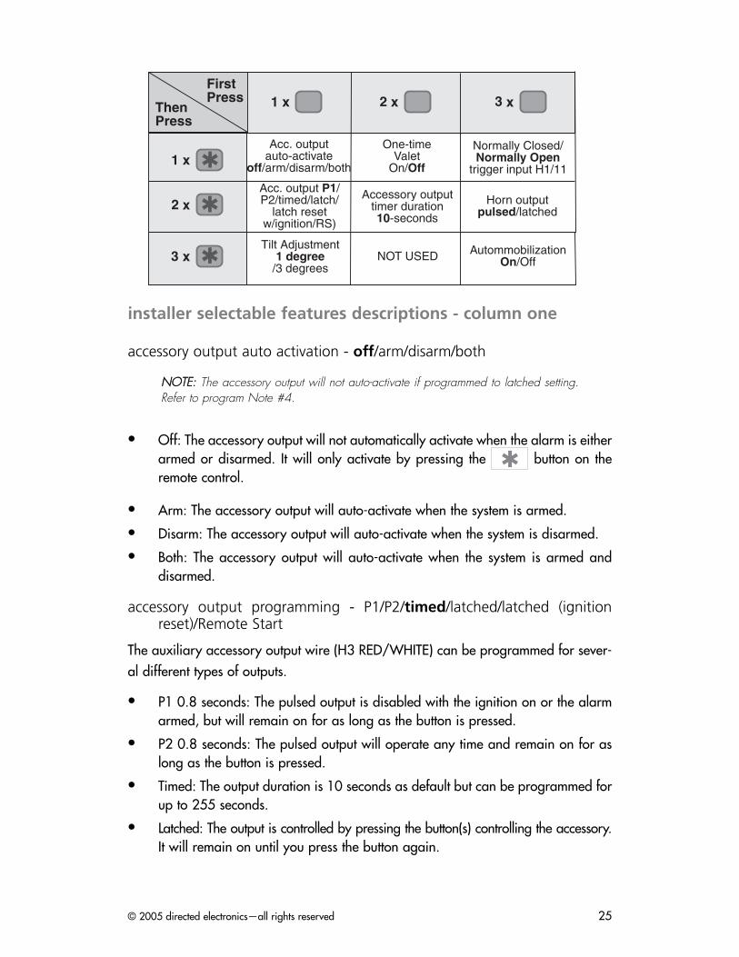
accessory output auto activation - off/arm/disarm/both
NNOOTTEE:: The accessory output will not auto-activate if programmed to latched setting.Refer to program Note #4.
Off: The accessory output will not automatically activate when the alarm is eitherarmed or disarmed. It will only activate by pressing the button on theremote control.
Arm: The accessory output will auto-activate when the system is armed.
Disarm: The accessory output will auto-activate when the system is disarmed.
Both: The accessory output will auto-activate when the system is armed anddisarmed.
accessory output programming - P1/P2/timed/latched/latched (ignitionreset)/Remote Start
The auxiliary accessory output wire (H3 RED/WHITE) can be programmed for sever-al different types of outputs.
P1 0.8 seconds: The pulsed output is disabled with the ignition on or the alarmarmed, but will remain on for as long as the button is pressed.
P2 0.8 seconds: The pulsed output will operate any time and remain on for aslong as the button is pressed.
Timed: The output duration is 10 seconds as default but can be programmed forup to 255 seconds.
Latched: The output is controlled by pressing the button(s) controlling the accessory.It will remain on until you press the button again.
����������
�������
��������������������������
��%%������ �&'�''
(��)���*���(�����
��������� � ������ ������)������
&��� � �������������
���+� � � )������
���������������$�
���+� � �����,��������������������
���%��������
-�����. �������������/���%����
�(-�0�1� � ��$���2�����(��
© 2005 directed electronics—all rights reserved26
Latched (ignition reset): The output is controlled by pressing the button(s) control-ling the accessory. It will remain on until you press the button again or if you turnon the ignition.
Remote Start: The channel is specifically programmed to be connected to the561T Valet remote Starter.
NNOOTTEE:: Setting for trigger input H11 must be programmed to normally open for prop-er operation.
tilt adjustment - 1 degree/3 degrees
This sets the sensitivity of the tilt sensor to either high or low levels of tilt change beforeactivation.
installer selectable features descriptions - column two
one-time valet - on/off
On - turns one-time Valet mode feature on.
Off - turns one-time Valet mode feature off.
accessory output timer duration - 10-seconds (1-255 seconds)
Start Timer: Press the button; the siren will chirp to signal the start of thetimer duration setting.
Stop Timer: Press the button; the siren will chirp to signal the end of the timerduration setting, or for maximum time, do not press the button.
NNOOTTEE:: The timer max setting is 255 seconds.
installer selectable features descriptions - column three
trigger input h11 - normally closed/normally open
Normally Closed: The alarm will trigger if H23 (BLUE wire) is disconnected fromground when the system is armed.
Normally Open: The alarm will trigger if H23 (BLUE wire) is connected to groundwhen the system is armed.
© 2005 directed electronics—all rights reserved 27
horn honk - pulsed/latched
Pulsed: H5 YELLOW/WHITE wire will generate a pulsing (-) output when thealarm is sounding. When arming and disarming the output does not operate.
Latched: H5 YELLOW/WHITE wire will generate a constant (-) output when thealarm is sounding. When arming and disarming the output will pulse as per thestandard chirp pulses.
automatic engine disable - on/off
When turned On the immobilization circuit automatically activates 30-seconds after , theignition is turned off, exiting Valet mode, or exiting programming mode. The H4ORANGE ground-when-armed output will not activate during Automatic Engine disable.
programming notes
NNOOTTEE:: When programming a new transmitter to custom configuration, an arm/dis-arm channel must first be programmed before programming the remaining channels.
Note #1: Adding a new transmitter in auto-learn configuration
Press the button of the remote control. The siren will chirp once to con-firm the new transmitter has been programmed.
Note #2: Adding a new transmitter in custom-configuration
For the Arm/Disarm channel press the button of the new transmitter. Thesiren will chirp once to confirm the new transmitter has been programmed.
For the rest of the channels press the desired button on the transmitter to learn,and the siren will chirp once to confirm that the channel has been learned.
Note #3: PIN Programming
A PIN code can have one to four digits; each digit can be from 0-9.
NNOOTTEE:: A PIN code cannot begin with a zero.

© 2005 directed electronics—all rights reserved28
Programming Procedure
1. Enter the feature location (column 2, row 1) in the user-selectable
programming grid.
2. Immediately press and release of the Valet switch.
3. Select each digit by pressing 1-9 times, and then press to enter the
number into the system. To enter a zero, press only.
To program a PIN code of 1032:
1. Press and release once and once. You will hear one chirp.
2. Press and release once. You will not hear a chirp after programming a
zero.3. Press and release three times, and then press once. You will hear
three chirps.4. Press and release two times, and then press once. You will hear two
chirps.5. Wait for two siren chirps after a five second pause or five seconds after the
last digit has been entered if using less than four digit code number.6. Turn off the ignition; the siren will chirp three times.7. The programming mode is now exited.
PIN Code Confirmation Procedure
Begin this procedure within 15 seconds of finishing the programming sequenceor the new code will not be set and the system will revert to the previous code.
1. Turn on the ignition.2. Enter the new PIN code.3. Press and hold for three seconds.
LED turns on: New PIN code is learned and programming iscomplete.LED stays off: New PIN code is not learned and the system reverts tothe old PIN code. Repeat the programming sequence.
Note #4: Accessory Channel
The accessory channel can be programmed to different types of outputs includ-ing a pulsed output that does not function when ignition is on or the system isarmed, a pulsed output regardless of the ignition/armed state, a timed output,a latched output, a latched output that resets with ignition on and a Remote startoutput for connection with a 561T remote starter.
The accessory channel can be programmed to auto-activate with the armcommand of the transmitter, the disarm command of the transmitter, or both.Auto-activate can also be turned off (factory default).
© 2005 directed electronics—all rights reserved 29
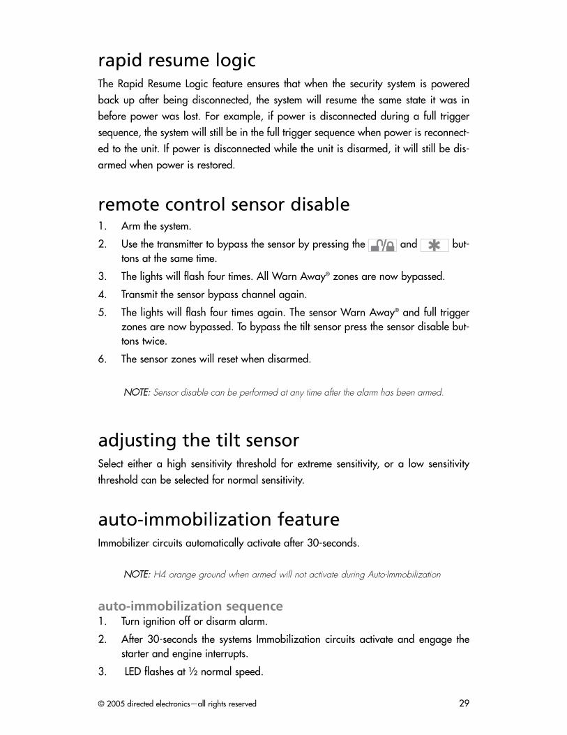
rapid resume logicThe Rapid Resume Logic feature ensures that when the security system is poweredback up after being disconnected, the system will resume the same state it was inbefore power was lost. For example, if power is disconnected during a full triggersequence, the system will still be in the full trigger sequence when power is reconnect-ed to the unit. If power is disconnected while the unit is disarmed, it will still be dis-armed when power is restored.
remote control sensor disable1. Arm the system.
2. Use the transmitter to bypass the sensor by pressing the and but-tons at the same time.
3. The lights will flash four times. All Warn Away® zones are now bypassed.
4. Transmit the sensor bypass channel again.
5. The lights will flash four times again. The sensor Warn Away® and full triggerzones are now bypassed. To bypass the tilt sensor press the sensor disable but-tons twice.
6. The sensor zones will reset when disarmed.
NNOOTTEE:: Sensor disable can be performed at any time after the alarm has been armed.
adjusting the tilt sensorSelect either a high sensitivity threshold for extreme sensitivity, or a low sensitivitythreshold can be selected for normal sensitivity.
auto-immobilization featureImmobilizer circuits automatically activate after 30-seconds.
NNOOTTEE:: H4 orange ground when armed will not activate during Auto-Immobilization
auto-immobilization sequence1. Turn ignition off or disarm alarm.
2. After 30-seconds the systems Immobilization circuits activate and engage thestarter and engine interrupts.
3. LED flashes at ½ normal speed.
© 2005 directed electronics—all rights reserved30
Disarm the system when immobilized
Use one of the following methods to turn off auto-immobilization
Turn ignition on and press the button of the transmitter.
Arm the alarm and then disarm the alarm.
Turn the ignition on and enter the system Valet/PIN code.
troubleshooting and system testingChecking arm/disarm.
Use the button on both remote controls to arm and disarm the alarm.
Use the button on the 3-button remote to silently arm and disarm thealarm.
Repeat both tests at required distance to test range.
Testing disarming without a remote
1. Turn the ignition On.
2. Enter the preset PIN code as described in the Programming Instructions section.
3. Then press the button once to disarm without a remote.
Testing the tilt sensor.
Arm the alarm with the motorcycle resting on its side stand. Wait at least 10 seconds.
Tilt the motorcycle upwards as though you were going to push it away. Thealarm should trigger.
Adjust sensitivity as necessary.
Testing Ignition Trigger.
Arm alarm
Turn ignition on, alarm should trigger.
Disarm alarm.
Testing the protection switch.
Arm the alarm system.
Attempt to remove the panel required to access the alarm control unit.
The alarm should trigger. Adjust or reshape protection switch lever if required.
Testing the N/O–N/C programmable input.
Arm the alarm.
© 2005 directed electronics—all rights reserved 31
Open or close the switch or circuit connected to the normally open/normallyclosed programmable input.
The alarm should trigger.
Testing the battery back up siren
Arm alarm.
Pull system 5 amp fuse. The alarm should sound. It should not sound for longerthan 5 minutes in total.
Reconnect fuse. Test system again to verify correct functions.
The system will not arm or disarm.
Make sure the ignition is not turned on or that the yellow ignition wire does nothave 12volts.
Make sure the systems 5 amp main fuse has been installed or is not blown.
The engine immobilization circuit works the wrong way round. i.e.. the circuit workswhen the alarm is armed but doesn't when the alarm is disarmed.
Check the correct normally open or normally closed wires have been used forthe bikes ignition circuit.
Check that the common wire has been used with either the normally open or nor-mally closed wire.
If normally open and normally closed wire is used the circuit will not work.
The Valet switch does not work.
Make sure that it is plugged in. (See the Plug-In Harness section of this guide.)
Check the System Features Learn Routine for the default PIN code.
Has the PIN code been changed?
The status LED does not work.
Make sure that it is plugged in and the red and blue wires are oriented proper-ly in the plug. (See the Plug-In Harnesses section of this guide.)

© 2005 directed electronics—all rights reserved32
© 2005 directed electronics—all rights reserved 33
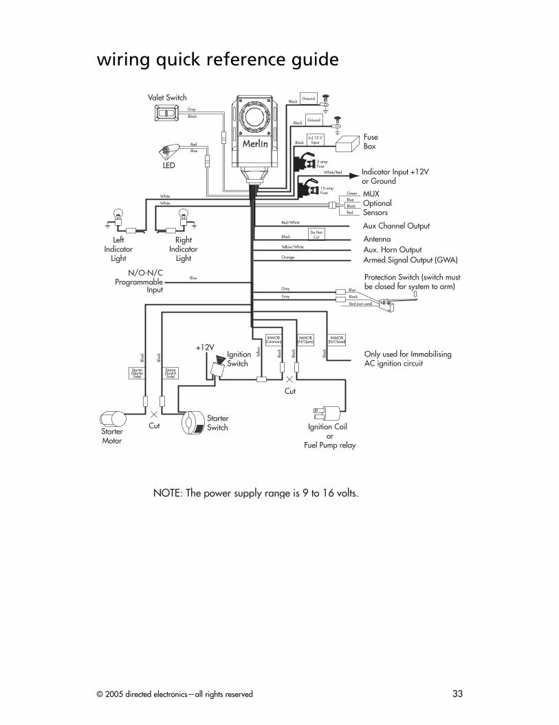
wiring quick reference guide
LED
StarterMotor
Ignition Coil or
Fuel Pump relay
LeftIndicator
Light
RightIndicator
Light
Valet Switch
Aux Channel Output
AntennaAux. Horn Output
Ground
Grey
Black
White
White
Starter(StarterSide)
Starter(SwitchSide)
StarterSwitch
Red
Blue
Cut
Do NotCut
Ground
Black
Black
FuseBoxBlack
(+) 12 VInput
5-ampFuse
15-ampFuse
Indicator Input +12V or Ground
Green
Blue
Black
Red
MUXOptionalSensors
Black
Red/White
Yellow/White
Armed Signal Output (GWA)Orange
Grey
Grey
IgnitionSwitch
+12V
Protection Switch (switch mustbe closed for system to arm)
Only used for ImmobilisingAC ignition circuit
Red (not used)
Black
Blue
Blac
k
Blac
k
BlueN/O-N/C
ProgrammableInput
Yello
w
Cut
IMMOB(Common)
IMMOB(N/Open)
IMMOB(N/Closed)
Blac
k
Blac
k
Blac
k
NOTE: The power supply range is 9 to 16 volts.
White/Red

© 2005 directed electronics—all rights reserved34

© 2005 directed electronics—all rights reserved 35
notes
________________________________________________________________________________________________________________________________________________________________________________________________________________________________________________________________________________________________________________________________________________________________________________________________________________________________________________________________________________________________________________________________________________________________________________________________________________________________________________________________________________________________________________________________________________________________________________________________________________________________________________________________________________________________________________________________________________________________________________________________________________________________________________________________________________________________________________________