Embed Size (px)
Citation preview

AUTOMATIC CONTROLLERS FOR THE APOLLO LCG
Samuel J. Troutman, Jr., P. E. and Paul Webb, M. D.
Final Report on Contract NAS9-9778
Prepared by: Webb Associates, Inc.
Yellow Springs, Ohio 45387
for Biomedical Research Office
NASA Manned Spacecraft Center Houston Texas 77058
June 1970
.N70-32752 0 ACCSS O NUMBE1 (2
R AD NuMBERI -CATEGORY1 Reproduced byNATIONAL TECHNICAL
. A.. . .... ........ INFORMATiON SERVICE.qfg 1,.W.:22151 .
https://ntrs.nasa.gov/search.jsp?R=19700023441 2018-07-18T05:47:12+00:00Z

AUTOMATIC CONTROLLERS FOR THE APOLLO LCG
Samuel J. Troutman, Jr. and Paul Webb
Final Report on Contract NAS9-9778
In the Apollo full pressure suit, body heat is removed with a liquid
cooling garment (LCG), which is connected to a heat sink in the astronaut's
backpack by means of a diverter valve that is manually controlled in three
positions to produce maximum, intermediate, or minimum cooling. For
some years, our laboratory has been working with automatic control approaches
for heat removal by LCG's, and the work to be described here was carried out
in response to a request from the Manned Spacecraft Center (MSC) to provide
them with automatic controllers which they could use in laboratory experiments.
There were two major differences between the controllers we had
previously developed and the ones needed for the experiments at MSC'. First,
the cooling garment would be the Apollo style LCG, rather than any of the
-previous LCG's we had worked with, so that the controllers would have to
match the new suit's characteristics; and second, what was actually to be
controlled was a diverter valve rather than a continuously adjusted water
temperature from a variable heat sink. MSC supplied us with an Apollo LCG,

2.
which we were to modify as necessary for control and testing purposes.
We were to use a heat sink run at a fixed temperature, 40*F, to simulate
the constant temperature heat sink in the backpack. The diverter valve
would continuously proportion the water flowing through the LCG either through
the cooler or around-it, thence back to the LCG, and in this way the temperature
of the water entering the suit would be adjusted. As an option to continuous
automatic control, the diverter valve was to have a manual override with the
same three positions used in the present Apollo hardware.
Two basic types of control were required, the first based upon contin
uously measuring the change in water temperature across the man (ATw) (or
heat extraction with a constant water flow), and, using this as the major control
input signal, add corrective information from a measurement of skin temperature
(T s ) on the man. The second approach was to use heart rate as the major input,
since this is indicative of the work level, and to use with this a corrective feed
back from the change in water temperature across the man. As a final option,
the heart rate controller should be usable without a corrective feedback loop.
When the three automatic controller circuits had been designed and
built, the diverter valve designed and built, the Apollo LCG suitably modified,
and a plastic impermeable outer coverall assembled, we proceeded to adjust
the controller circuits until they would operate with the clothing assembly.
Two subjects then carried out an arduous work schedule for a period of two
hours, one with the ATw-ATs controller, and the other with the HR-ATw
controller. The controllers were found to operate satisfactorily. All items
were then packed up and delivered to the Manned Spacecraft Center.
3.
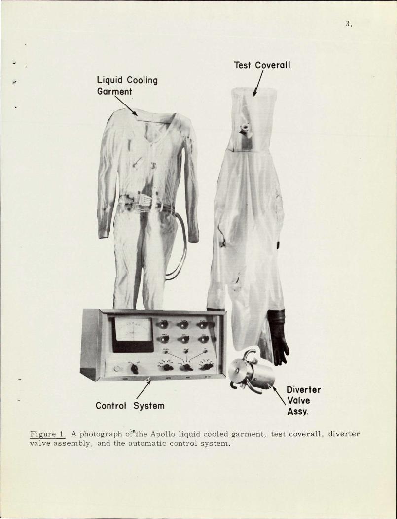
Test Coverall
- Liquid Cooling Garment
' I
Control System Diverter Valve
Figure 1. A photograph of'Zhe Apollo liquid cooled garment, valve assembly, and the automatic control system.
test coverall, diverter

4.
This report describes -the control logic behind each of the three controller
options, the nature of the diverter valve, modifications made to the Apollo LCG,
and the general features of the test coverall. Operating procedures were pre
sented next, then the results from the performance tests. In the appendices
are construction and design details of each of the four delivered items.
The Control Systems
Control of the heat removal capacity in liquid cooled garments as a
basic means of preventing thermal stress in active men while thermally isolated
has been firmly established (ref. 1, 2, 3). The method of control may vary;
however, the objective is to match heat removal to the man's heat production.
In our laboratory we have been successful in automating this control process
based on physiological responses related to water cooling (ref. 2 and 3).
Initial approaches required the temperature regulation of a cold water source;
however, in attempting to move closer to the control technique used in the
Apollo program, we have adapted our control logic to the diverter valve
principle, which simply mixes cold water from a constant temperature source
with the warm water returned from the outlet of the cooling garment, the result
being a new inlet water temperature.
This technique is currently controlled in the Apollo assembly by manual
selection of predetermined cooling levels, but to achieve proportional control
of the inlet water temperature required the design of a special motorized diverter
valve and controller. While hardware and logic are basic to automatic control,
of equal importance is the liquid cooled garment (LCG), since its performance
characteristics are considered one of the limiting factors in automating this
process. To complete the adaptation of the control system to Apollo type

5.
hardware, we used an Apollo long sleeve LCG (it does not include head cooling),
which was modified to interface with our control logic. To achieve a reasonable
amount of isolation in the laboratorywithout actual use of a full pressure suit,
an impermeable fuel handler's suit (Snyder, type P2010) was modified and worn
over the LCG. Since these components are important to the control process,
we will discuss them in detail in the sections to follow.
Control logic
Three control circuits were designed and fabricated to interface with
our diverter valve and modified Apollo LCG. The circuit logic Was based on
the inter-relationships of the following inputs: I) the difference between the
suit inlet (Twi) and outlet (Two) water temperatures (ATw) coupled with correc
tive feedback from the change in the mean of four selected skin temperatures
(ATs) (ref. 3); 2) the additive combination of the change in heart rate (AER)
and ATw; and 3) an optional mode of operation where the ATw is deleted as an
input and control is based on AHR alone.
The first control concept can be expressed in the following statements:
1. At rest, Twi, Ts, and ATw are constants;
2. As man goes to work, Ts and ATw will increase if Twi is held constant;
3. As control action lowers Twi, ATw will continue to increase and Ts
will decrease until the system seeks to stabilize.
The development of this control logic into a stable controller depended
on the establishment of an inter-relationship between-the control inputs and the
variable being controlled, Twi. So that the controller would be versatile with

6.
respect to initial conditions, the concept of differentials was employed, such
that all the parameters could be directly related to their original state. The
following expression resulted:
(G3) (Twi 0 -Twi) = (G1) (Two-Twi) - (G2) (Ts 0 - s) (1)
where: T wi = inlet water temperature, IC
Twi 0 = initial resting inlet water temperature, 0C
Two = outlet water temperature, 0C
Ts= mean of the control skin temperatures, 0C
Ts = Mean of the initial control skin temperatures, *C
Gi, 02, G3 = weighting factors or gains relating inputs to outputs (These are the three gain adjustments used in operating the controller cabinet)
The weighting factors of Equation (1) were determined by the substitution
of steady state values for the various parameters, based on the performance
characteristics of the LCG, until simultaneous solutions yielded values that
resulted in a reasonable prediction of Twi. These values for the LTw-ATs
mode are: G1 = 4.50; G2 = 0.90; and G3 = 5.00.
The second control approach can be expressed in the following logic
statements:
1. At rest, Twi, flTw, and heart rate are constants;
2. As man increases his activity level, HR will increase in proportion
to his activity;
3. An increase in HR starts control action, lowers Twi, increases ATw
until the system seeks to stabilize.
7.
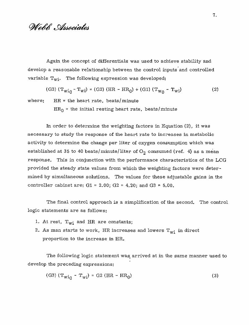
Again the concept of differentials was used to achieve stability and
develop a reasonable relationship between the control inputs and controlled
variable Twi. The following expression was developed:
(G3) (Twi 0 - Twi) = (G2) (HR - HR0 ) + (GI) (Two - Twi) (2)
=where: HR the heart rate, beats/minute
HR 0 = the initial resting heart rate, beats/minute
In order to determine the weighting factors in Equation (2), it was
necessary to study the response of the heart rate to increases in metabolic
activity to determine the change per liter of oxygen consumption which was
established at 35 to 40 beats/minute/liter of 02 consumed (ref. 4) as a mean
response. This in conjunction with the performance characteristics of the LCG
provided the steady state values from which the weighting factors were deter
mined by simultaneous solutions. The values for these adjustable gains in the
controller cabinet are: G1 = 2.00; G2 = 4.20; and G3 = 5.00.
The final control approach is a simplification of the second. The control
logic statements are as follows:
1. At rest, Twi and HR are constants;
2. As man starts to work, HR increases and lowers Twi in direct
proportion to the increase in HR.
The following logic statement was, arrived at in the same manner used to
develop the preceding expressions:
(G3) (Twi 0 - Twi) = G2 (HR - HR 0 ) (3)

8.
The values for the weighting factors are based on the same parameters
used in the second controller except now we have deleted the ATw input.
These gain settings in the controller cabinet are: G2 = 6.35, G3 = 5.0, and
GI = 0.00. It should be pointed out that these values have not been extensively
tested and are only approximations; further experimentation may require
alteiation of these values to achieve good control.
These control circuits were housed in a cabinet (8" x 9" x 1611), as
shown in Figures 1 and 20, with variable controls provided to allow the experi
mental selection of: 1) Twi 0 ; 2) Ts 0 ; and 3) the weighting factors of each of the
control inputs ATw, ATs, and AHR. In addition to these variable controls a
null meter and selector switches for mode control and HR 0 were provided to
assist in the operation of the controllers. Located on the rear panel of the
enclosure are the recorder output jacks-for each of the control inputs which
allow the continuous monitoring of the differential responses of the active
inputs. Also located on the rear panel is the connector for the cabling from
the diverter valve assembly which connects the valve to the, control circuits
(see Appendix D).
Diverter valve
A motorized diverter valve was fabricated to perform the proportional
mixing of cold and warm water to obtain the desired inlet water temperature.
The valve assembly was constructed with two modes of operation: 1) manual
selection of Twi based on the predetermined positions which allowed 0%, 88%,
and 94% of the return water from the LCG to be recirculated through the LCG;
2) motorized operation of the valve where the valve position is determined by
the control circuits. The valve proper is constructed of 303 stainless steel

9.
with Teflon bearing surfaces and consists of a stator, rotor, three water
connections, and a manual control knob. The water connections, identified
as 1, 2, and 3, are provided for connecting Two, Twi, and the cold water
source (40'F) to the valve mixing chamber. The manual control knob serves
a dual purpose of manual control and that of engaging and disengaging the valve
in the automatic position.
Motorized operation of the valve is achieved by engaging drive gears
located on the rear end of the valve between the valve housing and motor.
When engaged in the automatic position and driven by the motor, the valve
rotor rotates at approximately four revolutions per hour. This is a function
of the response times of the control inputs and control circuitry. The reduced
speed of the motor driven rotor also prevents overshoots in Twi resulting from
the unavoidable play in the two gears which are engaged and disengaged. The
rotor is limited in its travel to 320 by mechanical stops in the manual position
and limit switches in the automatic position. These limit switches are
arranged to provide bi-directional rotation when activated. The actuator for
the switches is located on the driven gear attached to the rotor and is only
active when in the automatic position.
The motor and gear assembly is mounted to the rear of the valve stator
and is covered with an aluminum can for protection. Also attached to the
motor housing is the cabling which connects to the rear panel connector on
the controller enclosure. This provides the power to the valve motor and
via separate connector connects the LCG instrumentation to the controllers,
which includes the thermistor probes (YSI 423) that measure the temperatures
of Twi and Two, and the temperature probes (YSI 425) mounted in the LCG
for measuring Ts (see Appendix B).

10.
Modified Apollo LCG
The Apollo LCG was modified to interface with our control circuits.
These modifications consisted of: 1) the location and installation of four
thermistors for the measurement of those skin temperatures selected to
represent skin temperature for control purposes. These are sewn into the
LCG in the areas shown in Figure 2 and are located between cooling tubes to
minimize the effect of the water temperature on the probes. These four probe
leads were brought together in a button junction and wired as shown in Figure, 3
and the necessary cabling brought out to mate with the cable to cable connector
located on the valve motor housing. The button junction was located and
attached to the outside surface of the LCG over the right lower abdomen;
2) the construction of special manifolds for the collection and distribution of
the water circulating through the LCG which would allow the installation of
thermistor probes for the measurement of the inlet and outlet water temperatures.
Two thermistor probes were mounted in each manifold, one for sensing the water
temperature for the controllers and the second as a reserve. The reserve probe
is available for the direct observation of these water temperatures without
affecting the controller performance. The instrument cabling was also brought
out to mate with the cable-to-cable connector, thus allowing the suit to be
connected to the control package via a single connection. The water lines
connecting the manifolds to the diverter valve were lengthened to approximately
4 feet and the standard Apollo self sealing quick-disconnect hardware removed
to simplify the procedure of donning the test coverall (see Appendix C).
The test coverall
A two-piece fuel handler's suit (Snyder P 2010) was purchased and
modified into a single unit for use as a test coverall. The basic modification
to the suit required bonding the top to the bottom and installing two zippers

LEFT BICEPS
RIGHT KIDNEY
RIGHT LOWER ABDOMEN
RIGHT CALF
Figure 2. Location of the control skin temperature sensors when the LCG is worn.

12.
RIGHT CALF RIGHT LOWER ABDOMEN
RIGHT KIDNEY LEFT BICEPS
Figure 3. Schematic of the network for averaging the control skin temperatures.
13.
in the rear for donning. The zippers were installed: 1) across the rear waist
line; 2) from the waist line up the right side to the armpit. These zippers
were provided with PVC flaps on the inside to reduce leakage while 6 cfm
of ambient air was circulated through the suit. To achieve this ventilation
it was necessary to install two gas flow ports, one of which was located in
the helmet directly above the forehead, the second just below the waist line
over the upper right thigh. The port located in the helmet was used as the
inlet and constructed as a right angle rotating joint, the outside of which
was connected to 4 feet of 1-1/4 " ID reinforced PVC flexible tubing while
on the inside a gas diffuser was attached to soften the air flow across the face.
The discharge port was designed to prevent an accidental shut off and instru
mented with a thermistor probe (YSI 44033) to measure the temperature of
the air being discharged from the suit. An additional port with a mouthpiece
was placed in the helmet for the collection of respiratory gases for analysis,
and a self-sealing pass-through was placed in the rear of the suit over the
left kidney for the egress of the LCG water lines and thermistor cabling.
Details of this assembly are shown in Appendix E.
These system components, the controllers, motorized valve, LCG,
and test coverall comprise the hardware required to test the effectiveness
of our control logic. Since our knowledge of the performance characteristics
of the Apollo LCG is based on only a few manned experiments in the laboratory,
further experimentation may require adjustments to the weighting factors to
achieve optimization in controller performance.
14.
Operating Procedures
In the preceding paragraphs we have described the hardware required
to automate our diverter valve control and now we will outline the procedures
related to the operation of the three controllers. From this discussion and
procedural outline one should be able to operate this control system in any
of its modes. The description of the operation of the system will be classified
as the standard procedure.
Certain steps in these procedures apply to all modes of operation
under standard or experimental testing; The first deals with the initial
operation of the valve in preparation for automatic control.
Diverter valve
The valve assembly should always be mounted in the horizontal
position, thereby preventing water from entering the motor housing should
.there be a leak in the valve seals. When the valve is properly mounted:
1) the manual control knob, Figure 4, should be fully depressed back
towards the water line connections. In this position the knob should rotate
freely from stop to stop (320);
2) with the control knob fully depressed, rotate the knob back .and
forth until the detent position is found;
3) while in the detent position, pull the knob out away from the housing
with a slight back and forth motion until it.is fully extended and the drive gears
are engaged. In this position the knob will not rotate freely;
4) with the valve engaged in the automatic position, connect the instru
ment cable to its connector on the rear panel of the controller housing;

15.
Manual
Control Knob
Figure 4. A photograph of the motorized diverter valve assembly.

16.
5) when this cable is connected (LCG cabling disconnected), turn
the controller power on and set the mode switch to AT/ Ais and allow the
control know to rotate to its full CCW position indicated by the alignment of
the reference line and dots on the valve housing;
6) turn the mode switch to the stand-by (STBY) position and the
controller power to OFF.
With the valve correctly positioned in the automatic position, the
control system is ready to be connected to the LCG once it has been donned.
The following steps are recommended:
1) connect the water line from the LCG manifold labeled "inlet"
to the valve connection #1;
2) connect the water line from the constant temperature source (40°F)
to valve connection #2;
3) connect the water line from the LCG manifold labeled "outlet"
to valve connection #3;
4) connect the instrument cable from the LCG to its mating cable
connector extending from the valve motor housing.
The LCG is now a part of the control system and the water flow to the
suit may be started and the following controller adjustments made:
1) set the "mode" switch to the STBY position;
2) place the "meter" switch in the ATw position;
3) set the "Ref HR" switch in the OFF position.
Standard AT/ ATs control mode
When the steps outlined above have been completed and this is the
selected mode of automatic control, the following steps apply:

17.
1) adjust the Twi reference control to indicate 2.80 (320C) and lock
the knob;
2) adjust the T. reference control to indicate 1.55 (330C) and lock
the knob;
3) set the ATw balance control to indicate 2. 10 and lock the knob;
4) set Gain #1 to indicate 4.50 and lock the knob;
5) set Gain #2 to indicate 0.90 and lock the knob;
6) set Gain #3 to indicate 5.00 and lock the knob.
With the "mode" switch in the STBY position turn the controller power
ON. Observe that the null meter has an on-scale indication, normally to the
right of center. Place the "meter" switch in the AT s position and observe
that the meter indication is on-scale (normally it may be to either side of
center), and finally switch to Twi and observe an on-scale meter reading,
normally to the left of center. This procedure checks the thermistors in the
LCG and manifolds and should an off-scale indication occur a thermistor has
failed. The position of the meter switch during any off-scale observation
indicates which thermistor to inspect or replace.
When the test subject is fully suited and properly connected to the
control system and the control variables adjusted as outlined, turn the "mode"
switch to the AT/ AT 8 position. This activates the valve servo motor and
initiates automatic control.
Standard HR/ AT control mode
This control mode requires an ECG wave form as an input. The
controller operates from a standard Wave form and only the magnitude of the
"R" wave needs to be adjusted to be compatible with the controller. This

18.
wave form and the recommended pulse height are shown in Figure 5. When
this signal has been obtained and the preparation procedures for the valve
have been performed, then proceed as follows:
1) adjust the Twi reference control to indicate 2.8.0 and lock the
control knob;
2) adjust the Ts reference control to full CCW and lock the knob;
3) adjust the ATw balance control to indicate 2.10 and lock the knob;
4) set Gain #1 to indicate 2.00 and lock the control;
5) set Gain #2 to indicate 4.20 and lock the control;
6) set Gain #3 to indicate 5.00 and lock the control;
7) determine the resting heart rate of the test subject by some means
and set the "REF HR" switch to it. Advance to the next higher position if the
heart rate falls between two of the values available on the switch;
8) from the ECG wave form source connect a signal of the proper
magnitude into the phone jack so labeled and located on the rear panel of
the controller housing.
With the "mode" switch in the STEY position, follow the same thermistor
test procedure outlined on page 13. In addition, it will be necessary to determine
if the HR circuit is performing and this may be determined by switching the "meter" switch to the HR position. One should observe an on-scale indication,
normally slightly to the left or right of center. If the indication is off center
by more than two small division, then the reference heart rate is either too
low or too high. It will be necessary to correct this by increasing the reference
one switch position when the indication is to the left of center and decreasing
the reference one switch position if it is to the right of center.

19.
When the test subject is fully suited and properly connected to the
control system and the control variables adjusted as outlined, turn the "mode"
switch to the HR/AT position. This activates the valve servo motor and allows
automatic control in this mode to be initiated.
Standard HR control mode
As in the HR/ AT control mode, an ECG wave form is required which
meets the parameters shown in Figure 5. The procedure is basically the same
for this control mode since it is a modification of the HR/AT controller. Repeat
the steps i - 8 outlined on page 14, with the following exceptions:
1) Ref. item #4, set Gain #1 to full CCW;
2) Ref. item #5, set Gain #2 to indicate 6.35;
3) Ref. item #6, set Gain #3 to indicate 5.00.
With the "mode" switch in STBY, follow the same thermistor test procedure
outlined on page 13, and determine if the HR circuit is performing using the
same method given in the previous control procedure.
Again, when the test subject is fully suited and properly connected to
the control variables adjusted, turn the "mode" switch to the HR position.
This activates the valve servo motor and allows automatic control in this mode
to be initiated.
Perform6.nce Tests
Laboratory experiments were conducted with the modified Apollo LCG,
initially using manual control of the inlet water temperature to determine per
formance characteristics, and finally automatic control to evaluate the perfor
mance of two of the controllers.
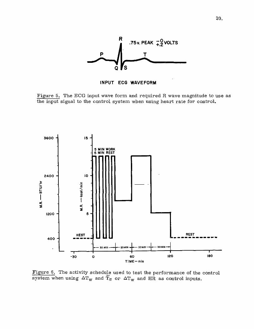
20.
.75v. PEAK . VOLTS
P T
INPUT ECG WAVEFORM
Figure 5. The ECG input wave form and required R wave magnitude to use as the input signal to the control system when using heart rate for control.
3600 15
5 MIN WORK 5 MIN REST
2400 I0
r
1200 5 qE I -
REST iREST
400 .". . . . .'. . . . ..
- " S35 MIN 4 -25MIN 4 -30MIN e--30 MIN
-30 60 120 ISO
TIME-min
Figure 6. The activity schedule used to test the performance of the control system when using ATw and Ts or ATw and HR as control inputs.

21.
Initial tests of the LCG were required to establish certain performance
characteristics related to water cooling and our control logic. The parameters
of primary interest were: 1) a resting inlet water temperature that would result
in a stable mean skin temperature between 32.5 and 33.50C; 2) the response of
the mean skin temperature during work while cooled; 3) the resting heat
removal from the LCG; and 4) an estimation of the effectiveness of the LCG
in removing metabolic heat from working men. These tests were conducted
with men at rest and working at two levels; 1200 Btu/hr (5 kcal/min) and:
2400 Btu/hr (10 kcal/min).
After the performance of the LCG was evaluated in this fashion, and
the control parameters determined, two experimental tests were conducted
using automatic control. The activity schedule for each of the tests was the
same. It is shown in Figure 6. These experiments were carried out in an
environmental chamber whose air and wall temperatures were maintained at
86°F (30 ± IC) with a dewpoint that was held between 26 and 31°F (vapor
pressure of 4 mm Hg) to minimize the heat loss from the test coverall due to
the 6 cfm air ventilation.
The LCG was part of a closed water loop containing the suit, diverter
valve, flow meter, circulating pump, and water cooler. In this loop the man
provided the heat source and the cooler the constant temperature (400 F) water
source. This arrangement is detailed in Appendix A.
Two healthy men, PW and ST, were used as subjects in the experiments,
both experienced in wearing water cooled garments. The subjects were different
in physical type and condition and their personal and anthropometric data are
listed below:
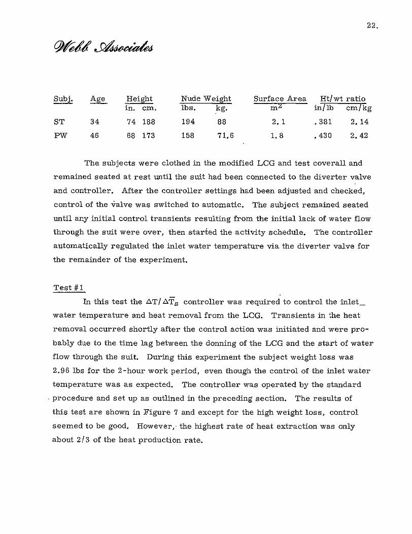
22.
Subj. Age Height Nude Weight Surface Area Ht/wt ratio
in. cm. lbs. kg. mZ in/lb cm/kg
ST 34 74 188 194 88 2.1 .381 2.14
PW 46 68 173 158 71.6 1.8 .430 2.42
The subjects were clothed in the modified LCG and test coverall and
remained seated at rest until the suit had been connected to the diverter valve
and controller. After the controller settings had been adjusted and checked,
control of the valve was switched to automatic. The subject remained seated
until any initial control transients resulting from the initial lack of water flow
through the suit were over, then started the activity schedule. The controller
automatically regulated the inlet water temperature via the diverter valve for
the remainder of the experiment.
Test #1
In this test the AT/ AT s controller was required to control the inlet
water temperature and heat removal from the LCG. Transients in the heat
removal occurred shortly after the control action was initiated and were pro
bably due to the time lag between the donning of the LCG and the start of water
flow through the suit. During this experiment the subject weight loss was
2.96 lbs for the 2-hour work period, even though the control of the inlet water
temperature was as expected. The controller was operated by the standard
procedure and set up as outlined in the preceding section. The results of
this test are shown in Figure 7 and except for the high weight loss, control
seemed to be good. However,- the highest rate of heat extraction was only
about 213 of the heat production rate.

110 -3360
100-M- 2880
90 2400
W 80 -1_ - 920
W0 14--40W 70
I.
60 A 960
50 ____- 480 ,-"SIj WORK PROFILE "
40 n. nd~ld' 0 0 20 40 60 80 100 120 140 160
TIME-min
Figure 7. Experimental responses of the inlet water temperature (Twi), heat removal (H), and the measured metabolic rate (A) obtained in automatically controlled test of the control system while using ATw and T. as control inputs,during activity schedule shown in Figure 6.
24.
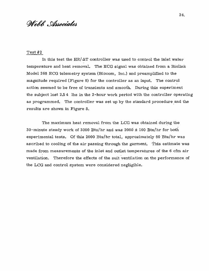
Test #2
In this test the HR/ AT controller was used to control the inlet water
temperature and heat removal. The ECG signal was obtained from a Biolink
Model 368 ECG telemetry system (Biocom, Inc.) and preamplified to the
magnitude required (Figure 8) for the controller as an input. The control
action seemed to be free of transients and smooth. During this experiment
the subject lost 2.5 4 lbs in the 2-hour work period with the controller operating
as programmed. The controller was set up by the standard procedure and the
results are shown in Figure 8.
The maximum heat removal from the LCG was obtained during the
30-minute steady work of 3000 Btu/hr and was 2000 : 100 Btu/hr for both
experimental tests. Of this 2000 Btu/hr total, approximately 50 Btu/hr was
ascribed to cooling of the air passing through the garment. This estimate was
made from measurements of the inlet and outlet temperatures of the 6 cfm air
ventilation. Therefore the effects of the suit ventilation on the performance of
the LCG and control system were considered negligible.

110 3360
100 A- -A 2880
90 2400
H
0
DW,, -80--%
1920
Ill a H
"ot=7 140Wa_
F-I IrI
60 -960
_4850 - - I - , ,
/ WORK PROFILE
40 n-n 0 0 20 40 60 80 100 120 140 160
TIME-min Figure 8. Experimental responses of the inlet water temperature (Twi), heat
removal (H), and the measured metabolic rate (AL) obtained in an automatically controlled test of the control system while using AT w and HR as control inputs during the activity schedule shown in Figure 6.

26.
References
1. Webb, Paul and James F. Annis. Bio-thermal responses to varied work
programs in men kept thermally neutral by water cooled clothing.
NASA CR-739, April 1967.
2. Webb, Paul, James F. Annis, and Samuel J. Troutman. Automatic
control of water cooling in space suits. NASA CR-I085, June 1968.
3. Samuel J. Troutman, Jr. and Paul Webb. Automatic control of water
cooled suits from differential temperature measurements. NASA CR
86244, August 1969.
4. Andrews, Robert B. Indices of heart rate as substitutes for respiratory
calorimetry. Amer. Industr. Hyg. Assoc. Journal 27: 526-532, 1966.

27.
APPENDIX A
The Cooling Loop
The entire cooling system, shown in Figure 9, was located inside
an environmental chamber near the subject. It contained a total water volume
of approximately 4 Ibs, which included all the hardware, tubing (1/4" ID Tygon),
cooler, flow meter, diverter valve, and LCG. With a fixed flow rate of 240
lbs/hr, the circulation time was approximately1. minute, and the system
pressure was normally between 2 and 5 psig.
Two pumps were used to circulate water through the system: 1) circu
lation of water through the LCG; and 2) continuous circulation of-water through
the cooler such that the cold water source could be controlled to 401F. .The
pump used for suit circulation was a roller tubing unit employing the peristaltic
principle and was taken from a Varistaltic Pump (Model 72-895-05, Greiner
Scientific). The cooler pump was a positive displacement, slung vane unit,
2 inches in diameter by 1-1/8 inches in depth. Both pumps were driven from
a single 0.25 HP DC motor which was electrically controlled to maintain a
constant flow.
The cooler consisted of three major components: power supply, thermo
electric modules, and controller. Control of the cold water supply resulted
from energizing 12 thermoelectric modules which provided a 3900 Btu/hr heat
removal capability. The modules were series connected and the hot and cold
junctions provided with water jackets. Tap water was used at the hot junction
as a heat sink while the cold junction water jackets provided the path through -
which the LCG water passed to be cooled. The cooler modules were powered

GAS DIVERTER 40 OFOUTPUT- TRAP VALVE
) -
INLET
THERMO- C LIQUID ELECTRIC PUPMANIFOLDS COOLING COOLER TRANSDUCER OUTLET GARMENT
MAIN -~~PUMP"""
GAS TRAP and
) P.S.I.G.
DAMPER
Figure 9. The cooling loop.
:°NFtO

wowdWb CoWAER5 C AS
=MVJ
.180
C2
cp CO
.74-03O7OQ
30cam a5
Figure 10. The manual control knob for the diverter valve assembly.

0UKSAPD~4L4Q.453
303 S.,a
Figure 11. The rotor and mixing chamber.
03

33.
port (0.0765 in. diameter) used during manual control for obtaining the 6%
cold water flow. A "stop pin" is mounted in one end plate that engages with
the stator when in the manual position to limit the rotation of the rotor to 320
and maintain the orientation of the rotor to stator.
A stator for the valve was constructed to provide the necessary sealing
surface for the rotor and to mount water connections from the valve to the
water loop. Its physical shape and size are shown in Figure 12. The stator
is #303 stainless steel and the inside wall is lined with a Teflon seal sleeve
to insure a complete closure of the two intake ports and prevent counter
currents between ports. To reduce the rotational friction, Teflon bearing
rings were mounted in the stator surfaces contacting the rotor end plates.
The stator end plates, one a permanent press fit, the other secured by eight
#2-56 screws, have through holes and O-ring seals for the rotor shafts.
In the permanent end plate is a slot which captivates the rotor "step pin"
when in the manual position. On the outer shell of the stator, three #303
stainless steel tubes labeled #1, #2, and #3 for connecting the water lines
are provided and orientated with respect to the rotor ports.
These components of the valve assembly are shown in their assembled
state in Figure 13. This assembly was placed in the suit and cooling water
loop and tested for leaks and flow characteristics. The valve was tested to
6 psig with intermittent pressures of 8 psig to determine if the assembly
was tight and the ports sealed. At a flow rate of 4 lbs/min, the predetermined
manual mixing positions were tested and found correct with a pressure drop
across the Valve of 0.1 psig.

34.
Figure 12. The valve stator.

IAoT v*ATeRk
35.
l-C I t
D 'PJCAP
VswscaE7
77711
/7
Figure 13. Valve assembly shown in
mANU iChq7ROL kA:ob
the automatic position.

36.
The servo drive motor (Model E-150-002, Electro Craft Corp.) and
gearhead assembly is shown in Figures 14 and 15, along with the mounting
brackets used to attach it to the stator. The gear (PIC G51-32) mounted on
the output shaft of the gearhead engages with the gear (PIC G51-64) mounted
on the rotor shaft to achieve motor servo control of the proportional mixing
of the cold and warm water flows. The rotation of the rotor in this position
is limited by electro-mechanical action. An actuator is attached to the driven
gear which trips limit switches located at each end of the 320 rotational arc.
To achieve bi-directional rotation.once a limited switch has been activated,
diodes, one each, are mounted across the switches polarized to allow reverse
current to flow through the meter. These diodes are mounted on the motor
stator.
The complete motorized valve assembly was tested for speed and
response to control command signals and found to perform within the design
goals, Additional drawings related to valve components. and construction
are shown in Figures 16, 17, and 18.

37.
Gear Head FAssy.
Motor
Figure 14. The motorized diverter valve assembly with the motor cover removed.

--
38.
Figure 15. The valve gearhead assembly.

.15LD " PttA. 2.2.8
2.21AbL.
1.0000
tot
'0- N
4-45*
Figure 16. A cut-away view of he valve stator.
Bo&a S.CC

*225 OB~ ee2.
17 nd pate 303S.S?iguestaorTh 9 r /0,.-.0

.656j
tvtbIA
WA.a ,OOODIA.
DIP. DI.
Figure 18. The servo motor mount. (ztteh CIdP St°

42.
APPENDIX C
The Modified LCG
The Apollo liquid cooling garment was furnished by MSC to be modified
to interface with our control system. This LCG with its modification is shown
in Figure 19.
The original manifolds were removed and replaced with new ones that
were instrumented with thermistor probes (YSI type 423) for measuring the
inlet and outlet water temperatures at a point near the suit. These manifolds
were fabricated from plexiglass and brass tubing to be physically similar to
the original-ones with respect to their size, shape, and flow characteristics.
The thermistors were located in the flow near the port which either delivered
or removed the total flow through the suit. They were mounted in this manner
to insure that the coolant temperature sensed would be representative of the
mean water temperature passing through the manifold. Two such thermistors
were placed in each manifold: 1) one in each manifold to be used as a tempera
ture input to the controller for determining the ATw across the suit; and 2)
one probe in each unit for independently measuring the water temperature
without affecting the control system.
These manifolds were connected to the four main distribition tubes
already a part of the LCG and also connected to the diverter valve with Tygon
tubing (1/4" ID x 4' long). The leads from the ATw thermistors were brought
out to form part of a cable connecting the LCG to the control system and the
second set of probe leads terminated with standard phone plugs.

43'
F r 9 hp iid
Figure 19. The modified Apollo liquid cooling garment.

44.
It was necessary to install as part of the LCG four skintemperature
probes (YSI 425) to measure the skin temperatures to be used as feedback
information in our control system. The thermistors were sandwiched between
PVC panels (0.625 in. sq. ) with the sensing surface exposed so that it could
make direct contract with the subject's skin. These probes are sewn into
the LCG between the cooling tubes in such a manner as to reduce the effect
of the cold water flow on the thermistor. The location of these probes was
shown in Figure 2. To achieve a mean skin temperature from these probes
they were brought together in a button junction mounted on the outside surface
of the suit over the right lower abdomen and electrically connected in the
series parallel circuit shown in Figure 3. The leads from this circuit made
up the remainder of the cable from the suit that connected to the controller.
This cable, which contained the leads from the skin temperature circuit and
manifold thermistors, was terminated with a cable-to-cable connector which
mated with the connector provided on the rear housing of the diverter valve.

45.
APPENDIX D
The Control System
Automatic control of the diverter valve, thus the inlet water temper
ature, based on the need for heat removal may be realized by any one of
the three control modes discussed in the preceding sections. In this section
we shall discuss in basic terms the electronic circuitry required to implement
these controllers.
The control circuits which comprise the three controllers are housed
in a single cabinet (8" x 9" x 16") that may be seen in Figure 20. This system
of circuits has been provided with controls and readout devices necessary for
calibrating each of the variables related to a specific controller; these controls
and readouts are located on the front panel of the cabinet for the convenience
of the operator. In addition to these controls, input/output connections have
been located on the rear panel for the purpose of obtaining or delivering
information to the control system, such as connecting the diverter valve
assembly, ECG wave form or analogs of the control variables for recording.
The component arrangement of the system is shown in Figure 21, which
is a view of the internal layout with the bottom panel removed from the cabinet.
These components related to power control and signal conditioning are assembled
on the chassis attached to the rear panel and are either a permanent installation
or mounted on plug-in printed circuit cards. The four such printed circuits
used in the control package are shown in Figure 22. The individual function
of each card is: PC-1 is the dual power supply for the logic circuits and the

46.
Faosi
Figure 20. A photograph of the cabinet used to house control system circuits.

47.
Figure 21. The component layout of the control system as viewed with the bottom panel removed.

48.
p
Figure 22. A photograph of the four printed circuit cards used in the automatic control system.

49.
servo control amplifier for bi-directional control of the diverter valve motor;
PC-2 is the signal conditioning circuits for the ECG input wave form (Ref.
Figure 5) and the reference heart rate generator; PC-3 is the circuits for
developing the analog responses of the control inputs of Twi, Two, Ts, and
the Twi feedback signal for valve control; and PC-4 contains the silicon
controlled rectifier (SCR) bridge which controls the bi-polar power applied
to the valve motor as regulated by the servo amplifier.
The schematic for the system of circuits is shown in-Figure 23, where
in addition to the logic circuits the valve motor and limit switch arrangement
are shown. An examination of this schematic reveals the 5 basic circuits,
each of which is associated with one of the 5 operational amplifiers (A-i
through A-5. The function of these circuits, the switching circuits and
their inter-relationship should become clear as each circuit is discussed.
Amplifier A-i is a differential device used to generate a voltage
analog of the difference between the inlet and outlet water temperature (ATw)
as a continuous signal. This analog is obtained by using a resistance bridge
which contains two dynamic elements (thermistors) to generate a voltage
proportional to the difference in the water temperatures. These thermistors
are located in the inlet and outlet manifolds of the LCG and connected to the
bridge circuit by the instrument cable from the diverter valve assembly.
This analog signal is then amplified by A-I to obtain +1.25 vdc/oC as the signal
then used for control. So that this parameter may be monitored, an output
connector is provided on the rear panel with a response of the same magnitude.

aH nil + 3T z STSY ' R'
R/2 SM;
AYT R2i 27W
Jiue. The1sche ai ofD uo ai 2hoto yt

51.
An analog of ATwi is generated by amplifier A-2 in much the same
manner with one small difference. In this case an additional branch is con
nected to the bridge circuit input of amplifier A-i, thereby allowing the ther
mistor used to measure Twi to serve a'dual function. This new branch consists
of a Twi reference control such that a reference signal proportional to the
initial inlet water temperature may be chosen (Figure 24) from which the
dynamic response of Twi may be compared. The result is a ATwi analog
which is used in two of the three modes of control as a feedback signal to
determine when the diverter valve has been positioned correctly based on
the other control inputs. The analog of this delta after amplification by A-2
has a magnitude of -0.316 vdc/°C. Again, so this parameter may be monitored,
an output connector is provided on the rear panel which has the same response
as the output from amplifier A-2.
An analog of the mean skin temperature change from the initial control
set point (Figure 25) is again obtained from a resistance bridge. In this case
the bridge circuit has four active elements but only their equivalent resistance
is used as the dynamic element for achieving a nATs voltage analog. This
equivalent resistance circuit is obtained from the LCG as discussed in
Appendix C. This signal is amplified by amplifier A-3 to a magnitude of
-0.94 vdc/°C, which is then used as a control signal. This amplified signal
may be monitored from the output connector located on the rear panel.
H-owever, this amplifier has several functions in the control system which
are .selected by the switch S3E; therefore the analog of the delta mean skin
is only obtainable when used as.a control input. When skin temperatures are
not used for control, this amplifier is used as a unity gain inverting amplifier
for the delta heart rate signal from amplifier A-4.

52.
440
420
400 -Twi SET POINT CURVE
380
360 _ _ _ _ _ _ _ _ _ _ _ _ _ _ _ _ _ _ _ _
I-
LI u) 340 -J 0
z O 30
,U z w W 300 Li
__ ___
280
260
240 22 24 26 28 30 32 34 36
WATER INLET TEMPERATURE
Figure 24. The relationship of the initial inlet water temperature to the Twi reference potentiometer set point. The circular symbol represents the settingused in the standard operating procedure.

53,
230
220 -T S
SET POINT CURVE
210 - _ _ _ _ _ _ _ _
200
I-190
IS 0 i- 18z 0-J
WJ 170
C
LL
i-'160
05
140 2D 22 24 26 28 30 32 3
MEAN SKIN TEMPERATURE
Figure 25. The relationship of the initial mean skin temperature to the Ts reference potentiometer set point. The circular symbol represents the setting used in the standard operating procedure.

54.
The circuitry associated with amplifier A-4 is that of the signal
conditioning and amplification of the ECG input and the reference heart rate
generator. The transistors Q1 and Q 2 are the active elements of the ampli
fication stages for the ECG pulse to obtain a signal level for triggering the
mronostable muitivibrator made up of Q3 and Q4, which generates a square
wave of 12 volts for 280 milliseconds at the frequency of the ECG input. This
generator has a maximum frequency response of approximately 200 cycles/
minute. The reference heart rate is generated from an astable multivibrator
comprised of Q5 and Q6 and has a square wave output of -10 volts at
selectable frequencies of 0 or 50 through 100 in steps of ten pulses per minute.
These pulses are then summed at the input of amplifier A-4, which is a
pulse integrator that generates an analog voltage proportional to the difference
between the ECG pulse rate and that of the reference heart rate with a magnitude
of -0.058 vdc/beat/minute. The output 6f A-4 is then inverted by amplifier A-3
and used as a control signal. An output connector has been provided on the
rear panel for monitoring this response.
Amplifier A-5 is the device which ultimately uses the control analogs
to control the power to the valve meter and its direction of rotation based on
the summation of these inputs as weighted by the Gain potentiometers GI, G2,
and G3. The output of this amplifier (A-5) controls the firing of the SCR bridge
which controls the 60 hz half wave power to the diverter valve motor to control
valve position. This power and phasing is obtained from a step down transformer
which has an output of approximately 14 volts p-p.

55.
The switches used to determine the mode of control are S3B, S3C,
and S3D. Switch S3B applies the Twi analog to the G1 potentiometer for
weighting prior to being amplified by A-5. Switch S3C controls the output
from amplifier A-i and connects the Tw analog to its gain control when it is
used as a control signal, and S3D selects the T s or inverted HR analogs as
required when their mode of control is indicated. Switch S3A is the remaining
section of S3 and is used to indicate the mode of control by lighting indicator
lamps on the front panel.
A null meter is provided on the front panel as an assisting device to
aid in the initial setup of a specific control mode or adjusting the initial
balance between the inlet and outlet sensors when they are sensing the same
water temperature. The indications of this meter are controlled by switch
S2 and any of the control variables may be observed to determine if they are
responding; however, the meter indications are not intended to be represen
tative of a response.
A list of components follows, keyed by number to the schematic of
Figure 23.
56.
Component
RI, R2, R3, RI8,R19
R4
R5
R6, R7
R8
R9, RIO, R21, R11, R12, RIB, R23
R14, R27
RI 5,
RI7, R42
R20, R3 I,R32, R33
R22
R24,R25,R26
R28, R29, R30, R46, R48,R50
R34
R35, R36, R43, R44
R37
R38
R39,R57
R40,R54
R411.
R45,.R47
R49
Components List
Description Amount
Resistor 2K±1% Dale MFF 5
100.0 ohm 10-turn 2151B Amphenol 1 5K 10-turn
2151B Amphenol 1
4.22K 1% IRC 2
220K ±10% carbon 1
100K ±1% Dale MFF 7
1 meg ±10% carbon 2
7.1K ±10% carbon 1
1 20K 25-turn Amphenol 992 2
10K 10-turn 2151B Amphenol 4
2.2K ±10%-carbon £
2.2 meg ±10% carbon 3
10K ±10% carbon 6
10K 25-turn 992 Amphenol 1
47.10 10% carbon 4
6.8K 10% carbon 1
22K 10% carbon 1
T 33K 10% carbon 2
47K 10% carbon 2
" 68K 10% carbon 1
1 680K 10% carbon 2
i 3.9K 10% carbon 1

57.
Components list, continued:
Component Description Amount
R51,R52 Resistor 1.5K 10% carbon 2
R53 " 42.2K 10% carbon 1
R55,R56 I 3.3K, 10% carbon 2
Cl Capacitor 150 MFD Kemet K150J 15S 1
C2, C3 I .01 MFD 25V Kemet 2
C4 11000 MFD Mallory 50 VDC 1
C5 i 120 MFD Kemet 1
C6 1 MFD Kemet KIC 20K 1
C9, C10, C1I, C12, C13,C14, C15, C7,C8 10 MFD Kemet 9
.1 Kemet KR IC 50K
D1,D2, D3 Diode IN4935 3
D4, D5 Hys. 170 2
DZ4 it IN4370 Zener 2.3 VDC 1
SCR1, SCR2 I 2N889 GE 2
QI,Q2,Q3,Q4 Transistor 2N 1304 4
Q5, Q6 " 2N 1305 2
A1,A2,A3,A4 Amplifier B-B 3007/15C 4
A5 " BD 3009/15C 1
Li Lamp Industrial Services type 1050C4 1
L2, L3, L4 " " 215004 3
TI Transformer Stancore TP-3 1
SI Centralab on/ off I
S2 Centralab-2000 SP,5P i.
$3 SP, 5P 1 S4 SP, 7P I
PS-301 ±15V power supply Phipps model 301 1
M1 Meter Simpson ± 500 MA model 1
J1,J2,J3,J4,J5 phone jacks Switchcraft 5
SCI Socket & Pin type Cinch Jones 1

58.
Components list, continued:
Component Description Amount
Dials, 1 thru 6 dials Amphenol type 1370 6
PI Plug-cable 7 Pin type Cinch Jones 1
Ft Fuse holder 1 amp Buss-HJM "1-
CBCI, CBC2, CBC3 Cinch Jones type 5b-2 2A-20 3
CBC4 Amphenol type 143-01 series 1
Power cord Belden BM-168 1
Chassis Bud CB-30 1
Cabinet Bud MD-1960 1
Cable Belden 8446 10 ft
Clamp Hayco type SR-5P-I 2
Motor generator reducer type 1
Valve type diverter 1
Housing-motor- Zero Manufacturing 1

59.
APPENDIX E
The Test Coverall
A test coverall was constructed from a 6 mil PVC fuel handler's suit
(Snyder, Type P-2010). This suit was modified into a one piece garment
and provided with the necessary ports for air circulation, egress of the LCG
water lines, and the instrumentation cables attached to the LCG. This
modified test coverall is shown in Figure 26.
The two-piece garment had consisted of a top section with a hood
which covered the arms, trunk, and head and a bottom section which covered
the lower limbs and feet. These two sections were bonded together at the waist
to form a one-piece garment. Two zippers were installed for donning the garment:
1) along the waist line running from hip to hip across the rear of the suit; and
2) running from the right hip up the right side to the armpit. The suit was
donned by entering the lower half with the feet and legs, then slipping the head
and arms into the upper section.
The hood covering the head required additional support for giving the
subject some degree of comfort. Therefore a 1/16 in. thick plexiglas disk
was attached to the top of the head. A frame of 1/8 in. diameter rod was
constructed and placed in the hood to give it a circular shape and vertical
support. The lower ring in this frame rested on the subject's shoulders,
while the upper ring of the frame supported the top of the hood and the disk.
Provisions for the required 6 cfm air flow through the garment were
realized by installing two ports in the suit. One of these ports was mounted
in the top surface of the hood; the other was located just below the waist line

60.
I
Figure 26. The modified test coverall.

61.
over the right thigh. The port in the hood was used to deliver the air flow to
the suit while the lower port was used for discharging the flow. The helmet
port was constructed of 1-1/4 in. ID piexiglas tubing and assembled as a
right angle rotating joint. The outside section of this joint was connected to
4 ft of 1-1/4 in. reinforced PVC flexibletubing, the other end of which was
connected to an air blower (Globe 100A104-7) used to push the air flow through
the suit. To the inside section of this joint a gas diffuser was attached to soften
the air flow across the face. This diffuser was also constructed of-plexiglas
in the form of a cup and 1/4 in. holes were drilled in the cup walls and bottom
for passage of air.
The discharge port was a simple pass-through tube made from 1-1/4 in.
ID plexiglas. To each end of this pass-through tube was attached a flat plate
perforated with 1/4 in. ID holes for gas flow. Additional holes were drilled
in the tube wall on both the inside and outside of the suit, thereby preventing
an accidental shut-off of the flow. This port was instrumentated with a thermistor
probe (YSI type 44033) mounted in the air stream for the purpose of measuring
the temperature of the suit discharge.
An additional port was installed in the helmet to which a mouthpiece was
attached on the inside next to the subject's mouth. This port was used to collect
respiratory gas samples for analysis during-the activity schedule. When not
in use, the port was sealed from the outside with a cork. This port was also
constructed of 1-1/4 in. ID plexiglas tubing.

62.
A final modification to the suit was required to allow the water lines
and instrumentation cables to be passed to the outside of the suit. A selfsealing port was constructed of 1/ 16 in. thick plexiglas sheet, stock and
II
rubber for sealing over the lines. The rubber was sandwiched between two
plexiglas oval disks and attached to the suit in the rear over the left kidney.
The rubber was cut in strips to provide overlaps and allow it to shape itself
to lines passing through the port and obtain a reasonable seal.