Embed Size (px)
Citation preview
5/13/2018 Naca Report 749 - slidepdf.com
http://slidepdf.com/reader/full/naca-report-749 1/18
REPORT No. 749
PROPELLER CHARTS FOR THE DETERM INATION OF THE
ROTA TIO NA L SPEED FOR TH E :MAX Il\1UM RAT IO
OF THE PROPULSIVE EFFICIENCY TO THE
SPECIF IC FUEL CONSUMPTION
By DA.VID BIERKANN and ROBERT N. CONWA.Y
of the ratio of the propulsive efficiency to the specific
A 8et of propeller operating e.:fficiency c harts, based on fuel consumption is also included.
a c oeff ic ie nt from which the p ro pe lu r r ota tio na l speed hall
been: eliminated, i8 presented. These c harts were pre-
pared 'W ith data ootained from tests of full-Biu m eta l p ro - P
peller8 in th e NACA p rop eller-re8earc h tun nel. W orking T.
c ha rts fo r n in e p ro pe lle r-b od y c om lrin aiic m 8 a re p rese nte d, Tin clud in g resu lts from tests of d ual-rotatin g pro peller8 . AD
These c harts are to be used in the calc ulatiffn of the W
range and the endurance of airplane8 equipped with 1 1 .
c onsta nt-speed pro pellers in w hic h, fo r given }ligh t c on di- LID
OOn8, it is d esire d to d ete rm in e th e p ropel le r r eoo lu tio n V
speed that gires the maximum ratio of the propullJive D
ejJiciency to the specific fuel cO'M'llmptio-n. The coejficient p
on whic h the charts are based may be written in th e form Po
of a thrust c oeffic ient o r a thru st-p ow er c oeffic ient. tr
A method of using the cham i8 outlined and sample q
c omputatio-ns for a ty pic al airplane are inc luded. C
SUM~URY
INTRODUCTION
Inthe calculation of the range and the endurance of
airplanes equipped with constant-speed propellers, the
thrust horsepower required for flight at a given gross
weight, airspeed, and altitude is known. It is desired
to determine, from the propeller-engine operating char-
acteristics, the propeller rotational speed that gives the
maximum ratio of the propulsive efficiency to the specificfuel consumption. The usual propeller coefficients are
insufficient for use in such calculations because knowl-
edge of both the engine power and the rotational speed
is required and these quantities are unknown.
In order to facilitate the calculations, the Bureau
of Aeronautics, Navy Department, requested the NACA
to prepare working plots of a thrust coefficient that is
independent of propeller revolution speed. The present
report contains such working charts for nine propeller-
body combinations and includes results obtained from
tests of dual-rotating propellers. .A . method that
can be used for the determination of the maximum value
SYMBOLS
power of engine, foot-pounds per second
effective thrust (T-IliJ), pounds
total propeller thrust
increased drag of body due to propeller slipstream
weight, pounds
propeller rotational speed, rps
lift-drag ratio
airspeed, feet per second
propeller diameter, feet
mass density of air, slugs per cubic foot
mass density of air at sea level (0.002378)relative density of air ( pI ~
dynamic pressure (lpVJ)
engine specific fuel consumption, pounds pel"
brake horsepower-hour
Q engine torque, foot-poundsC. speed-power coefficient ( { / ' _ p = v a ~ / P = - n - I )V/nD advance-diameter ratio
T. thrust coefficient G~~)Cp power coefficient ( p J ~ 7 3 = p . , i )
r, power disk-loading coefficient G r ~ V i ) ·
DISCUSSION
Inthe calculation of the range and the endurance of
airplanes equipped with constant-speed propellers it isdesired to determine, from the engine-propeller operat-
.ing characteristies, the propeller speed that gives the
maximum ratio of the propulsive efficiency to the
specific fuel consumption. The thrust horsepower re-
quired for a given flight at a given gross weight, air-
speed, and altitude is already known. .
The usual propeller coefficients of power, thrust, and
propulsive efficiency that are defined as
373

5/13/2018 Naca Report 749 - slidepdf.com
http://slidepdf.com/reader/full/naca-report-749 2/18
374 REPORT NO'-- 749-:-NATIONAL ADVISORY COMMITTEE FO~ AERONAUTICS
orOp=~- __pn _
Ol'=~·---pn-.u{ _
GT V.,,----=o.s»are insufficient for this purpose because neither theengine power nor the engine speed" is known.
In order to solve these special problems with the least.
work it is necessary to use plots of propeller coefficients
that do not involve the rotational speed. Suitable
forms of the coefficients may be obtained from the usual
thrust or power coefficients as follows:
TC7' T.
c=V / n D ) 2 p D 2 P
C' Cp pP =t t / n D ) 3 P . l F V 3
Because the brake horsepower is unknown, the equa-
tion for Op' should be multiplied by ." to obtain a thrust-power coefficient:
C, T. T
." p=~= e
The two general forms of the coefficient are ."P/plJ2V'
and TJpD 21T2 , which may be converted into engineering
units as follows:
."p 73300 thpP 1 J f V i = t 1D2(mph) 3
and
PROPELLER DATA
The propeller charts were prepared from data. ob-
tained in the NACA 20-foot propeller-research tunnel.
The tests that provided the data were made with tractor
propellers of approximately 10-foot diameter operating
in conjunction with various representative body types.A list of the charts and the basic propeller data are
given in the following table; principal model dimensions
are given directly on the propeller charts.
FigurePropeller drawing
number Rotation
Totalnumber
ofblades
Hamilton Standard:81M-6 _6193A-3_ •• ~ __31lilHL _
~---- ._-------3166-6, r,h._- _._ . ~318& -6, L h. • _8166-6, r. h. _ . __. _:&l8&-6, L h•. . _
Bnrean of Aeronautics:1 3 , 1 4 __ _ _ __ 6868-11 __ • _16,17 • ~ __. _
16 ,18_ ._____ 1i8e1H l ~
Body condition
Blade·anc Ie
r&IlItI at0.7SR(derl
Approxi-mate pro-oeller
diameter(ft)
1,2 __ . _3,4 _6, G •
7,8 __. _9,10 _
11,12 •
3 _ Streamline body, with spinner, on symmetrical wing .. ..:..._3 Streamllne body, with splnner ~--. .-- __-4 . _ Streamline body, with spinner, on symmetrical. wlnK. __._. .G do •• ~_
4 do ~
11IIII
II
2..do · ~-__..___---
3_ _ !Jqu id-ooo led engine nacel le , wi th sphlDe r_ .. •r__••__
3 Rad1aI en&Ine nacelle • ~ __ ~~-_-
4 Llquld·oooJed engine nacelle, with spinner. _._._~---------- __
10 Sln(le_. ____.. ~ t o l l S1l.lItI
. _ • • _ do________l I Q l o 5 l
10.____do ________
Z l t o l D10
_____do_______2l1o~
10 Dual. ___._•• _ ~ t o 5 l
10_____do. . . _____
2lto06
10 Slllf!le... .. . __ IUo e o10 __._do ___.__._ IIi to 4010 _____do._. . . . . . . . . 16 to 43
S4
3
PROPELLER CHARTS USE OF CHARTS
Two charts are provided for each of the propeller-body
combinations. One chart contains curves of. VjnD
plotted against Tc between 0 and 0.10 with contour
lines of constant.". The other chart contains curves of
T; between 0 and 0.40 and curves of ." plotted against
Vlnl). The same quantities may be read on either type
of plot but greater accuracy is obtained by the use of the
first type for the range of Tc values that it covers. Thesecond type of chart. is included because it offers greater
convenience in extending the range of T,values.
Itis possible that propeller charts of the typo given
in this_report may have a number of uses that- are not
anticipated at the present time. Also, it is quite
likely tha.t different methods can be devised for using
the charts in solving any specific problem. The chip!
object of these charts is, however, to furnish 8 means of
determining the optimum propeller speed for given
flight conditions to obtain the maximum ratio of the
propulsive efficiency to the engine fuel consumption.A method of obtaining the optimum propeller speed is
presented in the following outline, .
5/13/2018 Naca Report 749 - slidepdf.com
http://slidepdf.com/reader/full/naca-report-749 3/18
4.6
. .iii
I 4.40.I ! ' ; 4.2.III
4.0
3.8
3.6
3.4
3.2
3 . 0
2.8
y2.S
nI 12.4
2.2
Z. O
1.8
1. 6
1.4
1.2
1.0
.8
6Q \ .78', \ \
" i
40· II
j'.'
25·1--
5/13/2018 Naca Report 749 - slidepdf.com
http://slidepdf.com/reader/full/naca-report-749 4/18
.376
88
86
84
BE
80
t:-
; : . ; 78J
. §.u 76~.4b
~.74
t72~
70
58
66
-v
REPORT NO. 749--NATIONAL ADVISORY COMMITTEE FOR AERONAUTICS
v' -
KII" .A I ,x ,
1 _ I i ' \ . ~ r x k'V 7 ' .i 1 \ \ i\ / :04 '> '\1,-'"
~~~~~~~~H+~4-+H~~4-~~i~~~~i~~-H1'_~r+~'_r'~~
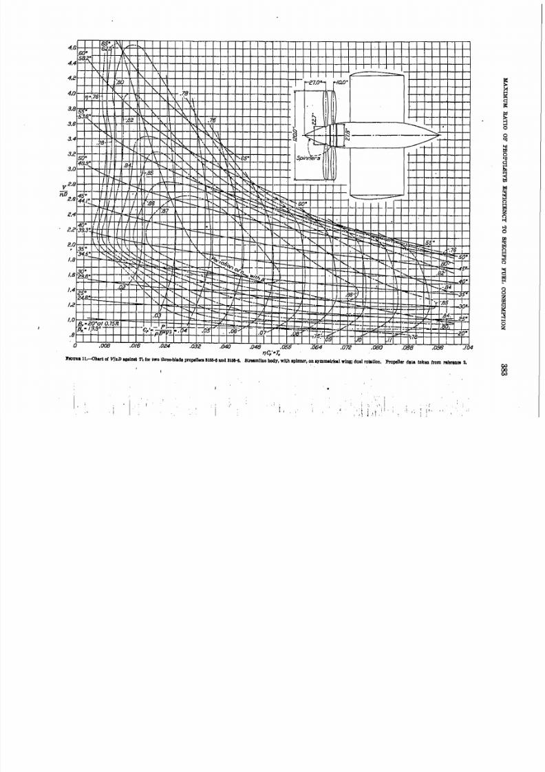
~o~ i f ? • ~Olo ,I .; P t a " 45° 150 1 /55· 1 /50 ' : :P-;;5S·-af() '7SR~~~~I~,Ii~/~I~II~I~/~~~I~~/~~~~-*~~~/~~-~+-~-rI'--'-a .2.llU 1.0 ie 1.4 /.6 1.8 2.0 es 2.4 es ee .!J.O se .3.4 .3.6 .J .8
V/nD
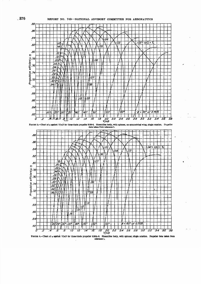
FlOUBE2.-Chart of, against VlflD for tbree-blada propeller 31M-e. streamline body, with spinner, ODIIJlIIIIletricI wing; a I n J l a rotation. rrupelltrdati. taken from rel6'enc6 1
Ie ../.. f " \ . \ ~ \ \ / V 1\ L'I\;::'3 V '\, ...OC=T}Cp-To .~_I-
.If",.!..
!~! ~\ II
:05 '/ \ ;' S , _ _--I-.~=---l--
ri' J \ I X I \ 1 \ \ \ / \ 1 \ / \ . . ' , / _ . - ~ -
. ~ 6 " , . _ r-, 1 \ \ I i \ \ X / I \ \If K
.~ z .;" '.1 ~ I \ I I /-\ I :++-+-t--tl--r-I--;-t-"-t'[7+-1f-1--I-I
. ' ? t o h. ,'\ \ I I /
.3c· f l\ Y ! I
I
.ee- \ I I /
I! II If 1 IIII
I /io ':a I ! If
If I! : 1
.'18, \ \/ J. \ .;07\ /
I
I 1I
"
I
I: 1
I.5~+-+~~J~rT-IH~~I/r+~~~+-I~~r+'_~-r+-l-+~r+'_~-r+-l
I :2 1f?5" ~O·'.35' ;40''~~~+~I~/~~+I1~~~~4+~~~r+~~~~~~~~4-~~~
o .2 .4 .6 .8 1.0 /.2
FIQ\1U 4.-Cbsn. of If a g a t m ' t VIlllJ lo r tbIee-blade propeller 6lWA--3. Streamline body, with sPinner; I ! i n & l e rotatioD. Propel ler data \ akeI l . fromrefereDoe 1.
5/13/2018 Naca Report 749 - slidepdf.com
http://slidepdf.com/reader/full/naca-report-749 5/18
~6~~~~~~~~~~rT-r~ro-''-Tl-..-.-~-r'-Tl-'''TllrT-r'-II-r'-Tl:T-r'-rT-rTi
I
/.8 " " ' I ~ ~ , • " \ - t : P -r-. ". ";;;;1 I, ~ r-~ ,~ ~r-: :: :J :;: :.b _ ....
\' V\f'"~~ . . -.:~'- r-, r-, \~~,:.::st-~r::;..-/.6 30:. ;\'\ \ 1'. • I ' : : I ' - . . . . <r-. ~ . '8 -' " F . : : : i - - - - , . ~ . . ; ;KM~~~~'I~~~ '-- ~J ~. 'I, "
' . . ~ : r ' f . # , "_-~-I-. !I"'" -
" K ~ ~ ~ _ r - ~ J - r - _ , - D~p - - y o - f-- rF t-1_-1- r-t- -._:../-,_ r - ' . . ,
I- C 1" j p 1 M i . . (04' t--.~F;'2'-I--_ t--r-/:'t-- - _....~_ - I t-=!-;::::f- 1-1"'-.86
/.0 I I: 1 1'-. I-I-~J::" - -I"- Il''_ --I-- r"'"" - t--r-17--p-eO·otO.75R I.ll .04' . 7 S 7r -r .. ;: !P " ", tf - ,__ -I'- -I-. -V
.8 I I I I I I Op- t - ; - , t J . 16, .07.1/ :8b- f-- t o . , I-_
I I I . I .'08
'-.
e . , . - . . .. . ./.2
'.85
- -~--~I\' -_...:~ _ _ p o . . . , _
• - --t- - • r-. ·:76
. \ - ~ - - ' - ~ 1 1 ' 7 : '4 •
r-, , j k < o
. 12 .'il"',l
25"
- -1-- ~O ". 1 1 .
.088 .096 ./04
~"
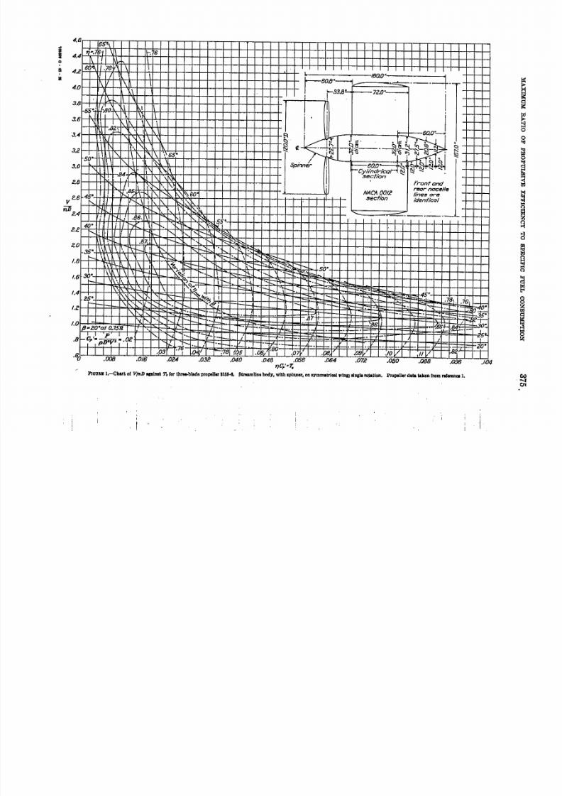
.60 .008 .018 .024 .OJZ .040 .048 .056 .064. q q .'" 1;
.o n .080
F'
! ;

5/13/2018 Naca Report 749 - slidepdf.com
http://slidepdf.com/reader/full/naca-report-749 6/18
I
nc.754.2 500~ ·t, •
1.0 30°_
I
,8~ I
I iI
II
· S O .008 .015 .080 .096 .104040 .tJ48 .0561 7 t : ; : - r . .
.072 .088024 .06403 2

5/13/2018 Naca Report 749 - slidepdf.com
http://slidepdf.com/reader/full/naca-report-749 7/18
REPOR'f NO. 749--NATIONAL ADVISORY COMMITTEE FOB AERONAUTICS 379
.88
"''''ILI-
~I,.- .t.
t""" I-K D - t - . . .
j_ r-, r-, ~ D < r- . . . - c=.eI , L . . r\. r-, I}\ ~ tv' . . . . . L/~\
.8C~f,J IV
" "
ti '\ IX I\,t r - . . . 1 / \ I i 1 \ \ IY \ 1 \ : 1~ 1\ t>
/- 1\ 1 \ i\ \ ' { ' II D < . O ? \ ) . (}.3= 7]Cp - x . 1/'.80/61:.?[L. \ Y , 1 \ I\, I\~j \ .
1 \ 1 '<\ I
.20' : ' - r - - _ I I I \ i 1 \ \ ~ \! ; \ 1 7 (7
.78.22', H \ 1 \ 1\ A \ I I .07 I 1 \ X 1 \ 1/
.7 6~1f - 1 \ \ 1 / \
.26 If' r f - . . \ 1 \ ; IY.'28 k ' " t. I I / I
.74 I I I; ~ I I t l II
I I II72
I / II
.70; I I II j I O !J Ii i !
.58I I II i ./ 2 II. I 1
-:14 ./0
.6620° I 1 /
..l \ 1 6 / I
25· ~O· I II.6 4
.3 .5" 40" i~ /5p o 55" 'i3. = 60 of a75'R
.6Z[ I I .
I Io .2 .4 .6 .8 /.0 1.2 /.4 is /.8 2.0 2.;: Z4 2.5 2.8 .3 .0 .3 .2 . .3.4 .35 .3.8
v/nD
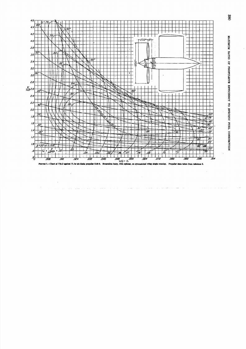
FIo!:BI G.-Chart of, against V / f 1 . D 1 ' 0 1 ' fonr-bJade propellel' 3IH Eti:'eiImlIne body, wlU! SPU!OO!',on 9l'mmetrieal wfnz;
slng!e rotat ion. Prope llel' data taken. from reference 2.
.M~-+~4-~~~~+-~-+~I£~_~~74~~_~~9,~~-~~~~~_+-~-+~~+-~-+~4-+-~
V r-...'./ ........-. . . / , , > < . . . . . . .- . . . . _
.~~~~~-+~~-+~~j~H~~~~,~~,~,~~4-~~X~~~+I/~~~~~4-~-+~+-~~~L r-, -/ [\. D \ . ' \ I i\ > < '
·~~~+-I-+~~I-+I/~~~~!'~~\~\~~~~~4-tOCM-~H-\~I/~~-+~~-+4-~~4-~~
'h./ \/ '\If \ \ \ \.~_f<..80~~+-~~+-.t~~+I~~~~~~\~~~\~~\~I~Y~~I~A~~~~~~~~~r+~~-+4-~~
I t .-J-~'\ , 1 \ 1 \ r - . , I \ 1 \ ' \ - , ' \
~78 .29{.1 1 - 1 ' - 1 1 \ I) 1 \ Y \ !.'\ \ \ I 1 \
~ I-+-I-+-+--+-22{/fr-!-l. \ \ i/ \ 1\ .~ II \.~76 ~~V 'U 1 \ J \ W
~74 .28i~ .....1 \ 1 \ Y '. . . . . . r e u - t .1l\ \ ,/ 1 \ 1 / \ I
I
II"1 \\
\ V
1 \ /I-t-
[\17II )
I I I / I i . I I I ..64~-+~+-~rl~~Hffi~H-~~~i~~~~~~~~~+-~-+~~~~-+~+-~-+~
~~~ar~~/~,~~/~~~~V~~h~/~~kd~~~~~~~~~+-~~.62 25" / 1.301/35" 1r40·1 4 5 ' 50· l i55" rso: ,; {Ja65"afQ75R.
I I I I I 1 / 1.5%~-.~c_L~.4~~.5~-~~~lO~~/,C~~/'~4_Ll~.6~~1.8~~c.~.O_Lc.~~~c.~A~~e~d~c.~~~3.~.O~~3.~C~3.~.
V/nDl! 'roUD: 8. --cbar t oC, apImt V/1ID for m-bJade propeller 3U6-G. StreamlIne body, with splnnet , on symmetrlcal wing; 5 I n s I e ~tIon. (The m" ell !.cfenor
carve was InterpoIated.) Propeller datil. taken. from reference 2.
5/13/2018 Naca Report 749 - slidepdf.com
http://slidepdf.com/reader/full/naca-report-749 8/18
VnJjc.6 45" r- .
: / 1>!c"1- - t-- •N~~:: : '<~ i'-. ~£.
- ; - . J . I - - , .B !. ;. .. \ - " " 1 1 - - - . - r -- . . . . . : ! ' :- . : : :: : ~ r - : :2.4~~4-~/~~/~.~~-....-4V~4-~-+\~~~_~~~~~'~~'.~I~,~~~~~~~~~r+~+-r4-r4-~-+~+-~-r+-~-r~
, . I I / - \ ~ - ~ I'~~~~
-
1'-'__
u~~~ ,/ .t~V ~~ ~ '-~~_ ~~~~
II -t--' I { ~ . . . . . . - - I- •' . ' - • ' : - - ~ - = . ~ :~ . .
\ . • \ 1 \ ' - - 1 "\ :- 1 - _ I~ . " . . . . . . . ~ ~ 1- I\' .... v r - ' " . " ' , . . . ..;.'S. \ \ \ • \ r-, - 1 ' - - : - 5 ? t . . . . . " \ - rr+ -... ~,~ _
1.8 r-:--,\-~ \." . '- I " " ' - : : > - ~ '1..... '-\
\, '. ~-~ "- 1 ~ •--
\ '\ '\ . , ' . . . . . . . - - ~
eo
• :~O·
.70 ;/6
r-45"-1 :Bq
1 \
I I1.6 10j_ . . . . - \
. r - - --1-- r-... _
- . . . .& .' "'"" 40·
. 8 ',J.5.':86 --~"(J5I';! i
- - - ' - - r-- --r-;t :If.
~-----JO .
2 ! > ·
TZ i i .
- 20·
: 7 C
5/13/2018 Naca Report 749 - slidepdf.com
http://slidepdf.com/reader/full/naca-report-749 9/18
--I-
/./1
.'8l!
.~~~~I~~~~I~~~~~~~~~~~~~_L~~~~~~~-L~~_L~~-L~~~~.008 .016 .024 .032 .040 .048 .058 .064 .072 .080 .088 .096 .104
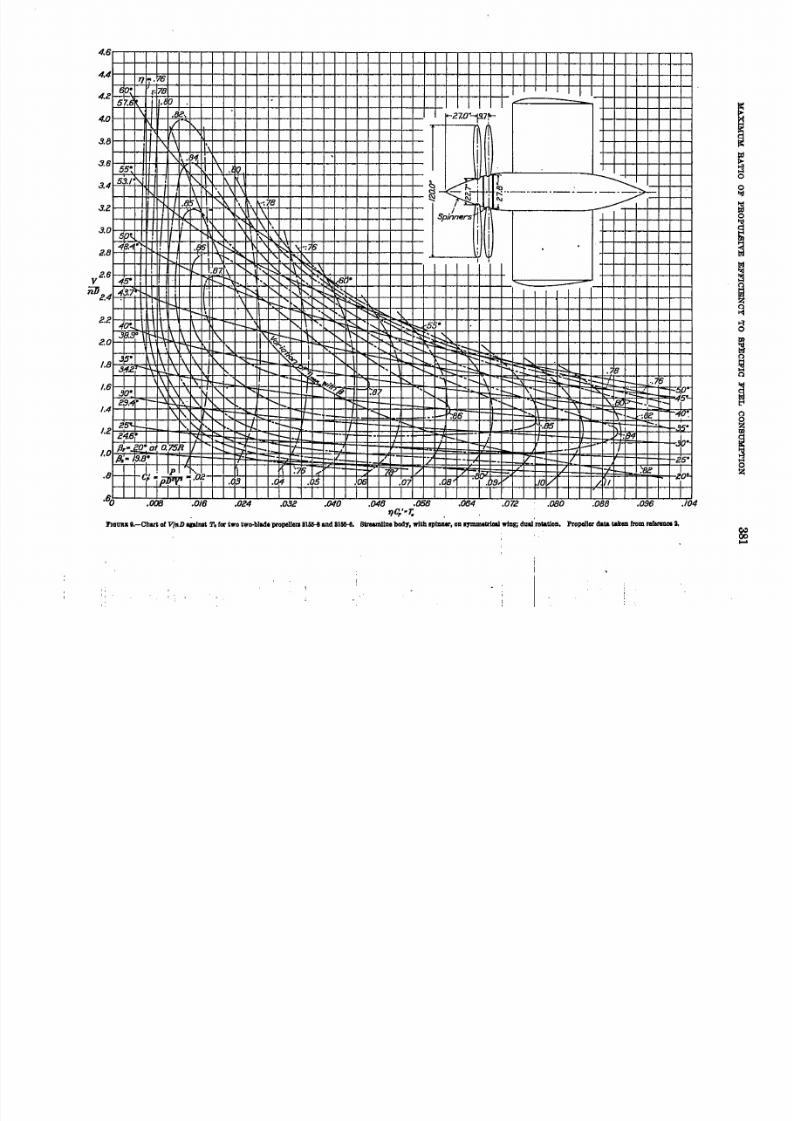
_ "e;: -7;.,J'JOtJIIJl:e . -Cha r t of V/fiD apIllit !l'. ro r t w o t w o- b ll d l p r op eU e ra 8 l J5 1 i. -ta n d 8 1 11 6 -8 . S U ' eI U l I ll n e body , with ap lDMr, Oil I Y JID I lt I; rI a a Iw l Il B ; d l l~ r ol a tl o ll . P r op e ll e r data t aken troD! r e tenm.c. i,

5/13/2018 Naca Report 749 - slidepdf.com
http://slidepdf.com/reader/full/naca-report-749 10/18
38 2
.88
.86
.84
.82
.80
1:-.78
~.91.76; g -. . . : :
lJ.74
~"
~.72
g .d : . 7 0
.68
.66
.64
.6Z
.600 .2
REPORT NO. 74g.... .., ..NATIONAL ADVISORY COMMITTEE FOR AERONAUTICS
/' r-/ ) 1 \ ~ \ \ . ' \ / \ . -7 --- f--
I L ! X \ X \ 1 \ - - -i I I \. I f \ . \ I [\ '\ r \ \ \ . ' I! 'r-1-t-+-t--t-t-I-:-=h~-F:t-M-IH+-;t-r-+T+\-1H-1-+-.t--'d-+-If-t-+-+--t-t-If-+-+,,-t-. ,--'r-_.' - -
~1j71 1 7 \ \ \ \ V I~~4-+4~.~~~v~*~4-.!~~~~~~~IV~~~~-t-+-~~-t-~~~4-~·-·-
.zcf.'rl--l 1 1 \ j \ 1 1 \ -+-t--t-+--I'- - ._
t-+--t=--+--:-t----l?!.~4 ,Lf-f . ._ j \ 1 \
;_,I[ It- j1-+--+--+-+-> '. jo 'C1t
Il-*!rJ'-.'--+*r\-++-ft-i-t-t!++-H-!IH-H-t-f+-+t-++-t--l++---t--H--+t-I-+-I--,···· -+--1-1-- ..~ ....-
. .3Z r-,"\ It-+-t-+-t-t'-+-'-:-f~\rt+-ltrrlHt-+t-tt-/:-+t+t-iH+~·O!-:;-7+t-t-+++-+-tiH-t--t-+-+-+-·t-+-I---t-·· -.-
~--+-t-+--I-tI--I+--M+\-H--t+-IIt-flI--tt--f-I--t+t-tII--H--t--fl++-I-I--!:=+--II-+-t-t-+-+.. --I-~-+--f-- 1 - -- - .I ! II
1-t-+-t--t-t-+t-t+~-h'tt-+-HHH-tt--t--++H-i-tt~-1+±:-I+t-+-7I---t-t-t-+-+--I--I-I~-"' ..-_.".I I I I: 08
.4 .6 .8 1.0 1.2 1.4 1.6 1.8 2.0 2.2 2.4 2.6 2.8 3.0 3.2 3.4 3.6 3.8VlnD
FIGURE lO.-Char t of ~qalnst V/flD fOl'two two-blade propellers 31M-(! and 3151H1. 8tresmlIne body, wl.tb spinner, on I)'mmetrlca1 wing; dual rotat loD.
PropeIler data taken !rum n!fereooe 2.
VlnlJ
FIaURE 12.-Chart 0( ~ aplost l'/IID for two three-blade prope lle rs 31~ sod 3156-6. Strelmllne body, with :<pinner, ODIymmetrlcal 'lliDg; dual rotatlou.
Propellel' det& t aken f rom reference 2.
5/13/2018 Naca Report 749 - slidepdf.com
http://slidepdf.com/reader/full/naca-report-749 11/18
3.8 5. •
3 . 8
S3.~j_
. . . . .
3 . 4 ~.78- . r-,
3.2 150 ·
3 . 0
4 8 . S ; _
:8 2
30 ·/.B 29.6·
= : : ~
1.4 2! 0
2
a .008 .016 .024 .032 .040 .048 .058 .064 .072 .080 .088 .096 ./04
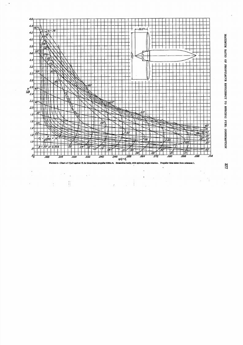
TlC/-r .J 't ou u l l. -< lb .r t 0{ V/nDAPlDlt T. ( M WD t hr ee -b la d o I lI 'o pe ll m 3 1M - II ~ d 8 lM - i1 . S1.reImJlIIll bod)" wn h lP lm:wr , 011 1) '1 II1II11I1oa1wbIJl dua l r ol il t. lo n . P ro pe ll er a a La t II ke n tram m8l'lllDII 2.
I .
II
' , " 1
I . ii,... [.~,
.I ., : ' I " . .. ,
5/13/2018 Naca Report 749 - slidepdf.com
http://slidepdf.com/reader/full/naca-report-749 12/18
z o e . .1.0
I /0 i f
~ ; !; I I
i i ~ I ! i, , , ,1
I, , I ~ i J
.080 .088 .096 .104
I
ii I i
1 , ~,i r I 1
,; ,
j I .': i I I I, <
.()48 .056 .~T J c , , ' _ r.
I1
.4 ,I : i
I r I,c;. ,
J ~ i II
.I l,
( ; I [
0 .008 .0/6 .024
, •
r I I1
j f § l
.032 . C U O
1 I
.072

5/13/2018 Naca Report 749 - slidepdf.com
http://slidepdf.com/reader/full/naca-report-749 13/18
MAXIMUM RATIO OF. PROPULSIVE EFFICIENCY TO SPECIFIC FUEL CONSUYPTlON 385
1-[...< I-.88~-+~+-~-+~+-~~~~~.~~~K~~v_~+-r_~-+~~+-~-+~-+-~-+~+-~~
/ f. 1 1 \ \ I\t!'-v X·~·~-+~+-~-+~~~~~~~~~\~~~-r/~~'~i~kl~~~/7-~~~~~~_+-~-+~~~~
; ' r V ' \ \/!\ v [f r x•..r
~-.IZ-["'rl 1/\l\ ,/\ J \ .05 J \ .04 V
.6 6I ,
V II
. . . . .'II 1 / I I IES" pa " \ 5 " 1 0 ' "'I..~ I hive I / s s · 1/'Yi = 50" af Q75R
~·r+-r~~U~I~lrF~F+~~rF~~I~~rT;-~~+-r+~~~4-~~
O~AEAWaU$m~UUUS~UM~~V/nD
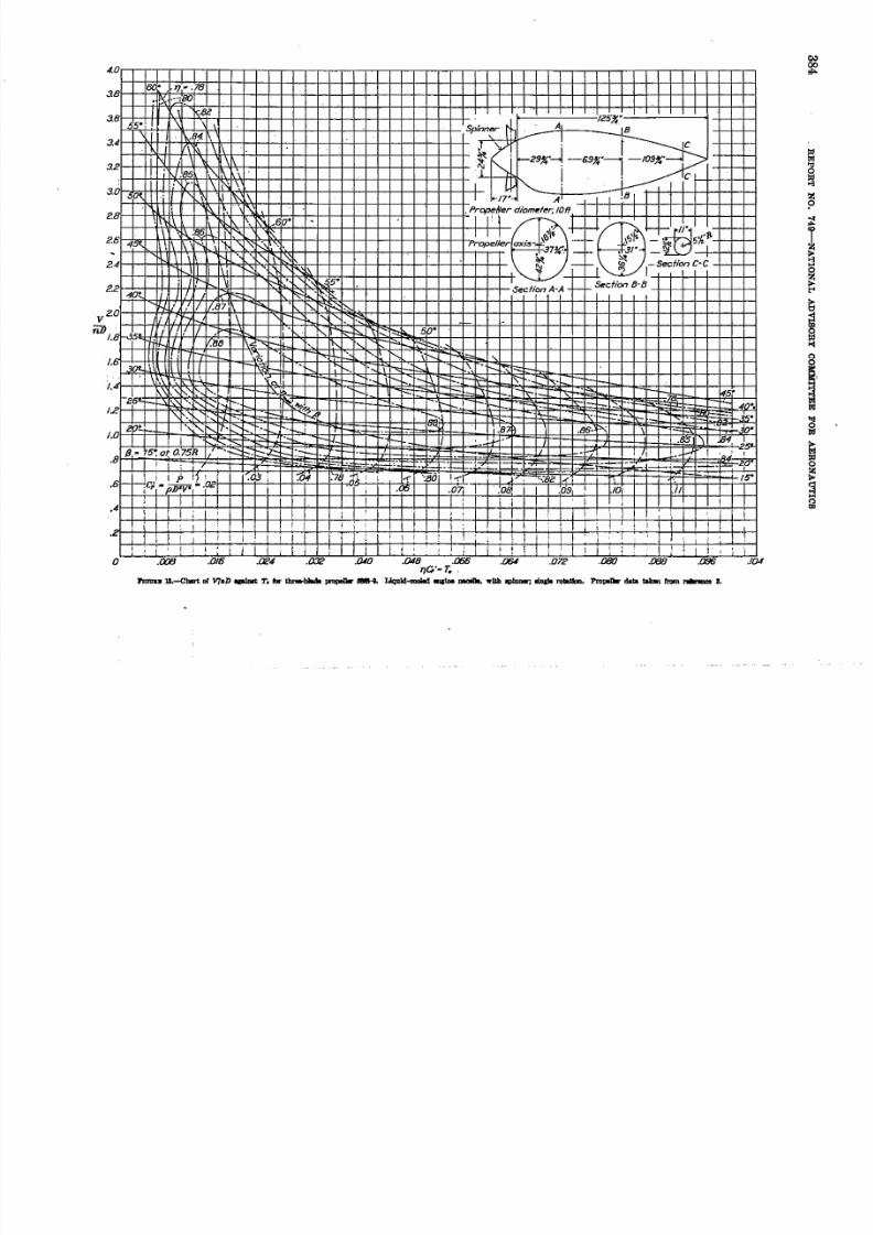
FrGuu l'--Charl 01. aplDsl; VIIlD ro c three-blIIde ~ o~ ~ L1qllid-eooled endne nacelle, with spinner, sIni Ie rot&tfou. Propeller data. takenf rom r ef er en c e &.

5/13/2018 Naca Report 749 - slidepdf.com
http://slidepdf.com/reader/full/naca-report-749 14/18
IUJ1-H--+-+-+--+-+--+-+-H"""",+-'+-+-+-+-+--+-HH-I--+++-+-~I-f--r-+
;
~----- 116" -------o!-1-f-j---J.-+-+-+--+-+--+--+--I-+-+-+-I-lH--+-+-+-+-+-+--+-+-i-
1
-+-+--i-+, PrOfH!lIer diameter, 10'
26~~~-4-+-+~~-+-+--+-~+-~~H~-+-+~~+--+-+-+-r-~~~-+I-+~~-+-+--+-+-~-~~~~-4-+~-~~-+~
,I
20-- I-1.0
.021
- I.8
/1-1 "at 0.7SR I
.6
.4I
.'
J
.2J ! ;
;
0.
.008
1 I 1 I ! i ! ~ I ; 1 ~ ;, ~ i I" [
! 1 r ! ) 1 I ,i
,.'
,I t I, , f I I , ~I ! ~ i
_L 1: I I I
,: i
1; r
,: ,
I I.016 .024 .032 .040 .048 .056 .064 .072 .080 . 08IJ .096 .104
7 J £ ? , ' . T ,.
5/13/2018 Naca Report 749 - slidepdf.com
http://slidepdf.com/reader/full/naca-report-749 15/18
1. 6 J ,.'0"'1--
1 - i1:5
1.2
E . G ! . .1. '0
.6
.
~
.76
- _ - r = : : : : : ~ : 1 5 J~5'
I'--~ .-'I-:~ BO- - " " ' :
~ -_- -. r-. .,_"l-_.'8
.B5~ i . '04
-- I
- '~.-.. --e, --. fje - : : : = : : : =.~
e8~-+-q~~~.~76~+-~-+~~~+-~-+~-r~+-~-+~~~+-~-+-r-r~+-~~-+-r~+-+-~-+~~,~+-~~
• i ·:1,9e6r~~-+Hr~~80~~-+~~~+-r-~~-+-r-r~+-r-~~-+-r-r~+-r-~~~-+-r-r'_+-+-~~-+-r-r~+--r-~
r - . . . . r . , ' . r,Be
L./.86. ---:r· _._ /_
--r·_,.....-- r-- -r." '"" •
. ! " 7 . - r -= , : . :: z . " -, . .. . , .. . 7---
~ ~8 ~f ~.' - •.II
'0 . '098(){)8 ,016 .032 . '040 .048 .0567 7 f 1 . ' - r ,
, '064 .'072 . D B D .(J88
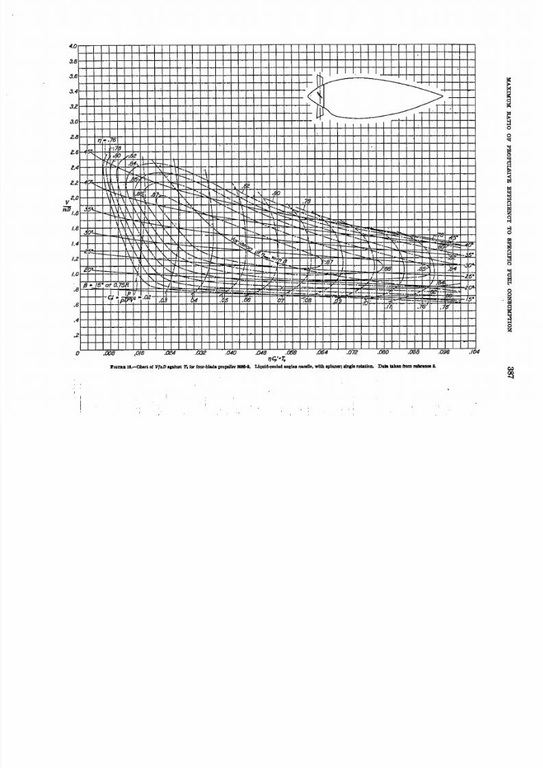
I'IQtJJt. Itl.-Ohar~ IIrVIII»apiDllt T.forrom·blad. propeJlH I 1 1 I I I & 4 , Llqllld~11!d m!la, lI.ceU~.wltII Iplnner; . J J I I I e rotaUOD, Data taken from rafIrIDoe &.
, I
.~
. .5·
p I .I)•
./04
5/13/2018 Naca Report 749 - slidepdf.com
http://slidepdf.com/reader/full/naca-report-749 16/18
388. REPORT NO. 749--NATIONAL ADYISORY COMlfiTTEE FOR AERONAUTICS
Given: Aerodynamic eharacteristies of airplane and
flight conditions:
(1 ) LID for speed of flight and altitude (or thrust
power for speed of flight and altitude)
(2) Weight, W
(3) Airspeed, t'(4 ) Diameter of propeller, D '
(5) Density at altitude, p
(6) Engine gear ratio
Characteristics of engine, including:
(1) Brake horsepower for altitude of flight as a
. function of engine _ speed and manifold
pressure
(2) Specific fuel consumption as a . function of
engine speed and manifold pressure or torque
.86
.8
f : : : . . kI ~ , , - ~ r - , I ? 1 " \
'"~ ~ I '\ . r \ . . r - ,'~4
.Ic.j. h < fil\f/ r\ ~05
'2 I £ - t\ "') \\1/:~,,~W ' _ ~ I V ~07
.,~ \ U '\ \ I V '.08
p n : - I . . " \~ T \ Ii'8
.c~.b-- f . . , . \ \ j
.c4. ' - 11 \ T .09"1]£;-r.0 .~ r-. \
.c 8 N \ ftjv'4
!\ 1 \ \I
'2I I
I I
o I II Ii
I ! I! /
I I ,- i I I
: ! j " I!
4I I
cO - I I
'2zs· ~ .
!'i! .p_-40·01 a75R
I
. 8 .
.80
~.7.
~g . . 7 1
& :
.68
.66
.6
.6
.800 .e .4 .8 .8 LO ie 1.4 1.6
V/nD
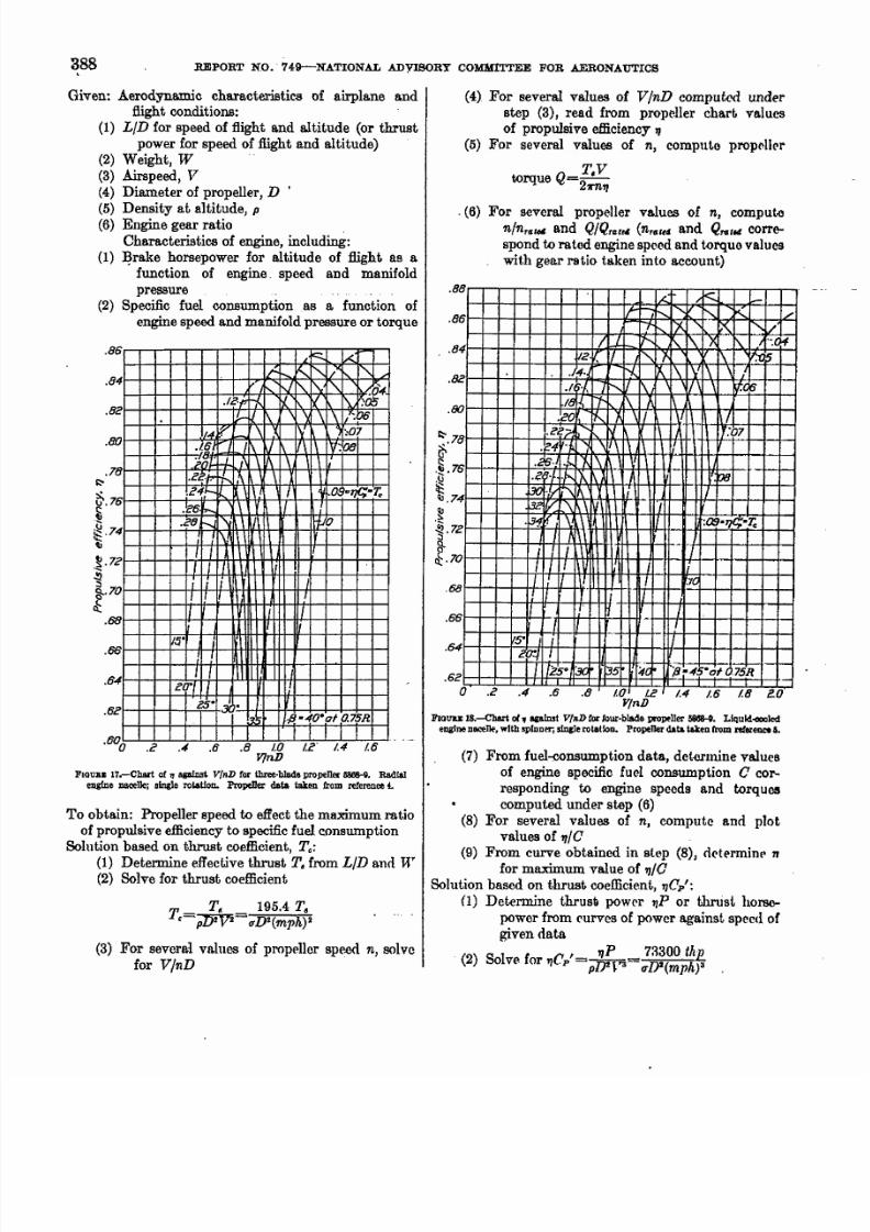
FIOUBJ: 17.-Chart of 'Iagainst V/nD for three·blada propeller~. Radialengine JlIICeIIc;single rotation. Propeller data taken from reference to
To obtain: Propeller speed to effect the maximum ratio
of propulsive efficiency to specific fuel consumptionSolution based on thrust coefficient, To :
(1) Determine effective thrust T. from LID and W
(2) Solve for thrust coefficient
TT, 195.4 T.
.=~= uD2(mph) 2
(3) For several values of propeller speed n, solve
for V/nD
(4) For several values of V/nD computed under
step (3), read from propeller chart values
of propulsive efficiency II
(5) For several values of n, compute propeller
QT.V
torque =2m'l
-(6) For several propeller values of n, compute
n/n'IJw and Q / Q r I J r e 4 (nrIJkd and Q " . r t l l corre-spond to rated engine speed and torque values
with gear ratio taken into account)
.88
,68
1 . . < : l< - i-
I f " " " " " r-,"r-, ~ -"
'"t t - . . . . IX K r-,.// !J. r- ~ 1\ ') < f\ _ _ I '~04
liz . II r - , r 1 \ V : ! l 5
J4· N, 1 1 \ 1 \ I V I \ \ l./~.[ 7r-, II 1 \ \ ~06
1 6 1 ' / ' rt- !\ ~.CO s . J \If V II
.ee»
"1 \ A 1:07
.~4 l' ' \ \ 1 \
.26- s : ~I\ \- ---.e r . J . · f . , . I " f . .
-1'00
30 : · 1 > " 1 \ 1 1 \ Y
~ f/. : \1 \ \ I.~ If \ . ! \ II :Q9.1JC;-r .
I ~ - ,/; JI I I I Ii
I T r r! I . ' / 1
[ T I T 1 i II
-I
I "_.f
:5 " i 1 72~ I
1 7 Z s o r x l 3 ! i ; # C f o /J-4S·ot .7SR
.86
.84
.82
.80
~.78
f,! ! .76. \ ; !
~1l1.74
~~.7Z
: : : l
8 -c l : : . 7 o
.66
.64
.6c
a .c .4 .6 .8 1. 0 I. C /.4 /.6 1. 8 eo'Y/nD
FJ:oUBJ: 18.-CIw1 01, apInst v/nD f«Iour·blade pt'OPfller~. Llquld-GXIlcd
ellifne naceIW,wIth spinner; slncIerotation. Propeller data taken r r o m refer_ 6.
(7) From fuel-consumption data, determine values
of engine specific fuel consumption C cor-
responding to engine speeds and torques
computed under step (6)
(8) For several values of n, compute and plot
values of 1 1 1 0
(9) From curve obtained in step (8), determine n
for maximum value of ' 1 1 0
Solution based on thrust coefficient, II Cp:
(1 ) Determine thrusa power liP or thrust horse-
power from curves of power against speed of
given data
,_ liP 73300 th p(2) Solve CorT jC p -pJ)2~"3--IT[)2(mph)3
5/13/2018 Naca Report 749 - slidepdf.com
http://slidepdf.com/reader/full/naca-report-749 17/18
!U.XIM.UY RATIO OF PBOPUI8IVE EFFICIENCY TO SPECIFIC FUEL CONBUMPrION 389
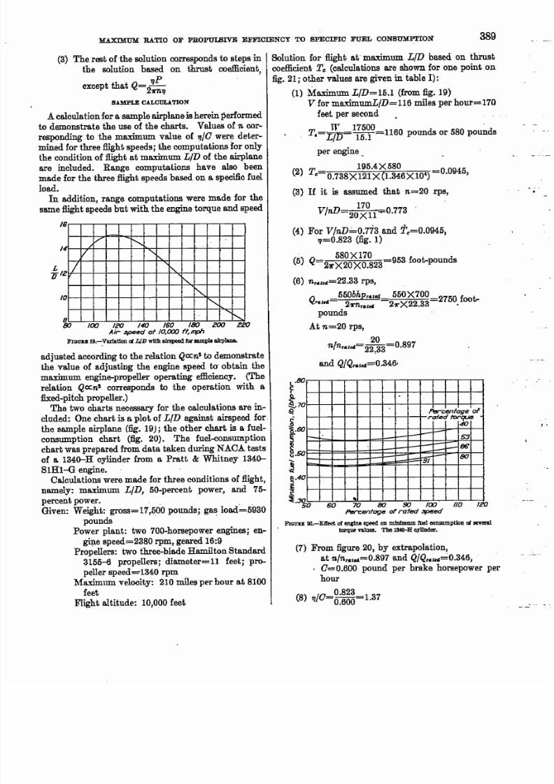
(3) The rest of the solution corresponds to steps in
the solution based on thrust coefficient,
except that Q=2f1P
r1l.f1
SAMPLE CALCULATION
A calculation for a . sample airplane-is herein performed
to demonstrate the use of the charts. Values of ' 1 1 .cor-
responding to the maximum value of 71/0 were deter-
mined for three flight speeds; the computations for only
the condition of flight at maximum LID of the airplane
are included. Range computations have also been
made for the three :Bight speeds based on a specific fuel.
load.
In addition, range computations were made for the
same flight speeds but with the engine torque and speed
I
I
S
'/ r-,V <,
'2_j r - ,
r - ,
0r-,r-,
<,
~80 100 120 140 160 180 200 eeo
Air ~d at 10,000ft.mphFIOOD I9.-Varlation r1 LI D with airspeed f«IIIIll1pJeairplane.
adjust-ed according to the relation Q c x : n ! to demonstrate
the value of adjusting the engine speed to obtain the
maximum engine-propeller operating efficiency. (The
relation Qcx:nt corresponds to the operation with a
fixed-pitch propeller.)The two charts necessary for the calculations are in-
cluded: One chart is a plot of LID against airspeed for
the sample airplane (fig. 19); the other chart is a fuel-
consumption chart (fig. 20). The fuel-consumption
chart was prepared from data taken during NAC. ! . testsof a 1340-H cylinder from a Pratt & - Whitney 1340-
S1H1-G engine.
Calculations were made for three conditions of flight,
namely; maximum LID, 50-percent power, and 75-
percent power. "Given: Weight: gross=17,500 pounds; gas load" 5930
pounds "
Power plant: two 700-horsepower engines; en-gine speed=2380 rpm, geared 16:9
Propellers: two three-blade Hamilton Standard
3155-6 propellers; diameter=l1 feet; pro-
peller speed=1340 rpm
Maximum velocity: 210 miles per hour at 8100
feet
Flight altitude: 10,000 feet
Solution for flight at" maximum LID based on thrust
coefficient Tc (calculations are shown for one point on
fig. 21; other values are given in table I):
(1) Maximum LID=15.1 (from fig. 19)
V for ma.-mnumLID=116 miles per hour=170
feet per second
W 17500 -T.=t/,tJ 15.1 =1160 pounds or 580 pounds
per engine_
195.4X580(2) T,. 0.738X121X(1.346X10.) 0.0945,
(3) If it is assumed thatn=20 rps,
V/nD 201~01l.....0.773 '
(4) For V/nD" 0.773 and 2\=0.0945,f1=0.823 (fig. 1)
" 580X170
(5) Q=2rX20XO.823 953 foot-pounds
(6) ' 1 1 . , & , , 4 = 2 2 . 3 3 rps,
Q5 5 0 b h p ' & l e d 550X700 r
~u& 2 r n , . & l u I 2rX22.33 2750 foot-
pounds
At '11.=20rps,
20n / n ' & l u I = 2 2 , 3 3 =0.897
and Q/Qnll4=O.34fY
~.80
I
t 7 0:Q
.
Percentage of
rated torque40
I--. -~53
B6
-~ 80b-
tl
f~. . .s o
!1 " 4 0~~ o 60 70 80 90 {(X) 110 le o
Percentage of rated .'!Ip6ecf
FIGlTU 2O.-EIfect of e n c I n e speed on mfnImum fue l consumption 01 several
t«qUP vaIllM. The I34O-H cYlInder.
(7) From figure 20, by extrapolation,
at ' 1 1 . / ' 1 1 . 1 & 1 1 4 = 0 . 8 9 7and Q / Q , & 1 . 4 "0.346,
• 0=0.600 pound per brake horsepower per
hour
(8) 7I/O=~:~~=1.37

5/13/2018 Naca Report 749 - slidepdf.com
http://slidepdf.com/reader/full/naca-report-749 18/18
390 REPORT NO. 749-NATIONAL ADVISORY COMMtTTEE FOR AERONAUTICS
(9 ) 'f}IO is plotted against n in figure 21, together
with the corresponding values of Q , 0, and
~, which have been added as a matter of
interest. From this figure it is seen that the
maximum value of 'f}/O occurs at n=13.7
The results of similar computations for flight at. 50-.
percent and 75-percent power are given in table 1.
The range for the three flight speeds was calculatedfrom the Breguet range formula:
L fI WoRange, miles=863 1 5 ( ) log 10n',
where H'o is the gross weight and We is the gross weight
less the gas load. .
In the Breguet formula, LID is assumed constant
and the values of 'f}/C are average during flight i whereas,
the values of file as used in the problem are for the
start of flight.
For maximum 'fI/Oat maximum LID,
Range, miles=863 X 15.1X 1.62XO.181=3820
With the data from table. I, the range at 50-percentpower was computed as 3680 miles and at 75-percent
power the range was 2940 miles. The variation of the
1.3
,. ,/56
/'/
C'\v '/'r 54
_ ,0 ../ . -- -
~\. ~ - r! l- 62-, ff' l-i--> S . . ~'IC
- -
/ V<, . . . . . .'- -
60r-,
V / r-.< <,~. ,/
. . . . . . . . < 48
r - . : . . <
t--f--
/46
j
IClO(r
1.9.88 2000
1.8 .86 IBOO
1.7.84
i '7
1.6 ;8Z
1.5.80 teoo
1 .4 .78
162 /4 15
n.rps
FIGL'KE 21.-Varlatlon of eIll1ne-propenor operating characterilltlOll for 1lIJht
at maximum L{D of 5 8 D 1 p J e airplane.
13 17 /8
I I I .'
.Cantrollable-P/!-ch p r c ; -t- 7S-percent- r pef/eii# 8ef for- cOnclitionfXJ .WEr r-:: : : : : : : :~ -:«maximuin'r,!C'
-
<~ <,
<,r-,50-percen~ower ...-
'\.
"-"I.
Fixe)pi,!", . l - o p 9 / ~ set'" 1 \ - \ t--to absorb rated power at \Qted engine Speed for high-3peed-fllght condilion I
JI Moximiln L/~
I
180
120
100NOO Z6IXJ ZBOO 3000 3ZOU 3400 36IJO 38G IJ
Range. miles
FIOVBIi:22.-ComlJ8l'lson of flight rang!'S for fixed· and controllable-pitch prolX'lJers
on sample airplane at 10.000teet. The foregoing comparisons were based on
\'a lu es o f "IC fo r the start of tI lif ht. I ns te lld o f on a v er & gC v a lu e s Il!I stipulated In
the Bregoet formula .
range with the airspeed is given in figure 22. For
comparison, figure 22 contains 8 plot of the range for the
same airplane equipped with both controllable and
fixed-pitch propellers, the fixed-pitch propeller being
set for the condition of high-speed flight. Because the
gain in range by the use of controllable-pitch propellers
Bet for maximum engine-propeller efficiency was rela-
tively small for the conditions assumed in the samplecomputations, it would appear that the optimum blade-
angle setting is fairly close to the high-speed setting.
The stating of such a generality is hazardous, however,
chiefly because the fuel-consumption data herein pre-
sented may not apply to engines in general.
TABLE I
CALCULATION OF . " / e
Flight constants , . 11 Q() C
at start of Jllght (rpI!) l'/nD
" Kr.t.' (rt-Ib) Q;. . . . (l~rl~e
--
r0.77 ( ) _ 8 2 3 (I.m e~ 0.345 ( ) _ 1 i O O Lr;
LlD-lli.l : 1 1 1 . 1 1 2 • ! 1 28 .&2 D I M ! .3Il2 . lI86 LU18 .!II .831 • ! 10 7 10.50 .382 . 8 7 1 1 1.45
t' -116 mph ! 17 .;1 .8311 . 7 63 1100 .400 . s e a 1 . 1 1 116 . g n .MIl .718 1110 . 4 2 1 1 . 5 4 & I.M
T -1l601b I l~ I .DI •MIl .1Ii2 12 30 .U8 • S I l l 1 .871.10 .84% , 1 ! 28 1330 .~ . 5 2 1 1 I.I i : !
: : = - i II r.is .RI0 . 1 1 8 3 1(90 .M2 . 505 1.811.211 .760 .&38 17 :10 .8211 • o I8 D I.m
~--L/ !
.90 ( ) _ 1 1 4 7 1.03 1 2 1 1 0 ()_~ o .m 1.40
.; 4 .8IiO .1lI7 1300 .471 • & 1 1 0 LS2
.fill .8M .~ 1360 .4!15 .646 1.57I 20 1.03 .880 .!f11 142 0 .515 . 530 1.82
V -llllimph 18 l . 0 I I .8&7 .852 14110 .638 .617 1.ilII18 l . 1 6 . I 1 1 I I I .IBT 1M O .M7 • S O li 1.72
T -l3IiO Ib; 17 1.21 .8G6 .iU 11150 .Il0:l .~~ 1.7&16 1. 5 .887 .718 liS) . 1 1 - 1 8 . 4 1 1 0 1. iR
T, ~0.OOI6 16 1.38 .84% .872 IG3Q . '1l!2 .W 1.81It 1.48 .1124 .Im 2110 .7t1 .480 1. 'Ii13 l . 6 f I •is) .1i83 ftOO .m .m 1.71
-----_.----f------2lI 1.10 0._ 1.03 11UO 0.705 n . 1 I I I l ' 1.71
LlD-W.O 22 1.111 .871 .® 2020 .73a .497 1.7521 1.20 .1172 .!K2 2 12 0 .770 • - 1 85 I.S!
t· ~ll1Omph 20 US .871 .So 2:llO .1110 .470 1.&Ig 1.33 .865 .852 l I850 ,W .4!!2 1.87
T - l7I!O Ib 18 1.40 .M1 .807 3610 . 1 1 1 3 .4~ 1.8817 L,", :844 .763 2700 .Q82
:::~~:I. ~()_0530 18 Lilli .830 .71816 L8!I . 800 .1!72
LANdLEY :MEMORIAL AERONAUTIC.'.L LABORATORY,
NATIONAL ADVISORY CO:r.UUTTEE FOR AERONAUTICS,
LANGLEY FIELD, VA., December 11, 1940.
REFERENCES
1. Biermann, David, Hartman, Edwin P., and Pepper, Edward:Wind-Twmel T~t-8 of Propellers Equipped with Spinners,Cuffs~ Airfoil and Round Shanks, and NACA IS-Series
Sections. N ACA Rep: to 00 published.·2. Biermann, David, and Hartman, Edwin P.: Wind~Tunm'lTests of Four- and Six-Blade Single- and' Dual-RotatingTractor Propellers, Rep. N o . 747, NACAr 1042.
3. Biermann, David, and Hartman, Edwin P.: Tests of TwoFull-Scale Propellers with Different Pitch Distrlbutlons, atBlade,Angles up to 60°. Rep. No. 658, NACA, 1939.
4 . Biermann, David, and Hartman, Edwin P .• Tests of FiveFull-Scale Propellers in the Presence of a Hadial and aLiquid-Cooled Engine Nacelle, Including Tests of TwoSpinners. Rep. No. 642, NACA, 1938.
5. Hartman, Edwin P., and Biermann. David: The AerodynamicOharaeterlstica of Full-Scale Propellcrs Having 2, 3, and
4 Blades of Clark Y and R. A. F. 6 Airfoil Sectlons, Rl 'p.
No. 640. NACA. 1938..