Embed Size (px)
Citation preview

CONFIDENTIAL Copy No. RM No. L8K24a
NACA
RESEARCH MEMORANDUM EXPERIMENTAL AND CALCULATED HINGE MOMENTS OF TWO AILERONS
ON A 42.7° SWEPTBACK WING AT A MACH NUMBER OF 1.9
By
James C. Sivells and Kennith L. Goin
Langley Aeronautical Laboratory Langley Field, Va.
\# -V
.0
Thl.
^ ffezting the t - fee Wfthrn th
I the cited f140tC a.td employe
ITtrt)t wtf h C 109 a, Ooot to 'nitad °tatas
'C
NATIONAL ADVISORY COMMITTEE FOR AERONAUTICS
WASHINGTON January 19, 1949
CONFIDENTIAL
https://ntrs.nasa.gov/search.jsp?R=19930085830 2018-06-21T15:02:09+00:00Z

NACA PM No. L8K24a CONFIDENTIAL
NATIONAL ADV]LORY COMJIPThE FOR AERONAUTICS
RESEARCH MEMORANDUM
]EMAL AND CALCULATED HINGE MOMENTS OF TWO AILERONS
ON A 42.7° SWEPTBACK WING AT A MACH NUMBER OF 1.9
By James C. Sivells and Kennith L. Goin
SIJIVIMARY
A 42.70 sweptback wing was tested with basic and blunt ailerons in the Langley 9— by 12-inch supersonic bloydown tunnel at a Mach number of 1.9 and. a Reynolds number of 2.2 X 100. The wing had an aspect ratio of 11., a taper ratio of 0.5, and an 8-percent-thick symmetrical biconvex airfoil section in the free -stream direction. The interchangeable 20-percent-chord ailerons were located outboard. The profile of the basic aileron vas 'made to conform to the contour of the wing, and the profile of the blunt aileron had flat sides and a trailing-edge thickness of one-half the hinge-line thickness.
The rolling-nament coefficients of both ailerons varied approximately linearly with aileron deflection, and the blunt aileron was about 10 per-cent more effective than the basic aileron. Hinge moments varied approxi-mately linearly with angle of attack and with aileron deflection for both ailerons and were about 40 percent higher for the blunt aileron than for the basic aileron. Theoretically calculated hinge moments were in good agreement with experimental results. There was no measurable difference in the drag of the two wing-aileron combinations.
INTRODUCTION
A general transonic and supersonic investigation has been conducted in several facilities of the Langley Aeronautical Laboratory of the lateral control characteristics of a 11.2.79 sweptback wing of aspect ratio of 11. and taper ratio of. 0.5, with 8-percent-thick biconvex airfoil sections in a streamwise direction. Free-flight tests (reference 1) and wind-tunnel tests on a transonic bump (reference 2) indicated a reversal in aileron effectiveness in a region of the transonic speed range for a conventional 20-percent--chord aileron with the basic wing profile. Tests of the same configuration at a Mach number of 1.9 in the Langley 9— by 12-inch supersonic blowdown tunnel (reference 3) verified the free-flight results which showed no reversal in the higher Mach number range. In an investigation instigated to improve the aileron effectiveness, it was
CONFIDENTIAL

2 COOEIAL NACA RM No. L8K24a
found that certain aileron section profiles would eliminate the reversal in effectiveness (references 2 and ii). One of the more promising profiles tested had a blunt trailing edge with thickness equal to one-half the airfoil thickness at the aileron hinge line and had flat surfaces (references 4 and 5). In order to investigate the characteristics of this blunt aileron at a Mach number of 1.9, a wing fitted with such an aileron was tested in the Langley 9- by 12-inch supersonic blowd.own tunnel. Reported herein are the results of this investigation which include aileron hinge-moment and rolling-moment characteristics. For the purpose of com-parison, the characteristics of the basic aileron with biconvex sections are included. The wing was tested in the presence of a fuselage at a Reynolds number of 2.2 x 10⁶.
SYMBOlS
I CL lift coefficient L=A
C(Drp"
D drag coefficient ( q.$)
Cm pitching-iment coefficient Pjtchin moment about 0.25 ( - qS )
(Roflin moment C.1 rolling-moment coefficient \. 2qSb )
Ch hinge-moment coefficient( Eine moment about hinge axis \ 2q (Moment of area about hinge axis))
S entire area of semispan wing including part covered by fuselage (17.943 sq in.)
mean aerodynamic chord of entire wing area (3.101 in.)
b twice the distance from the wing root chord to the tip (12.000 in.)
q free-stream dynamic pressure
a angle of attack relative to free -stream direction
deflection of left-wing a.1eron in plane perpendicular to hinge line, positive when trailing edge is deflected. downward.
CONFIJDEIffIA.L

NkCA RN No. L8K24a COIFIDIIAL 3
M Mach number
R Reynolds number, based. on
MODEL AND TESTS
The aeniispan wing and half-fuselage are shown in figure 1, and their principal dimensions are given in figure 2. The wing is the same as that described in reference 3 and has an aspect ratio of 1 and a taper ratio of 0.5. The airfoil profile very closely approximates a circular-arc section in a plane normal to the quarter-chord line. The airfoil section parallel to the air stream is approximately 8 percent thick, and its ordinates are given in table I. The steel wing and brass fuselage have polished surfaces. In mounting the wing and fuselage in the tunnel, the root end of the wing was displaced from the axis of the fuselage in order to make the exposed wing area approximately the same as in references 2 and 14• The root end of the wing serves as the reference axis for the rolling moments. Two wing models, identical, (within con-struction tolerances) were used in the tests: one, for obtaining hinge-moment measurements and the other, for obtaining the aerodynamic charac-teristics of the complete wing. This was done because the aileron installation used in measuring hinge moments was neither as smooth nor as rigid as the other aileron installation. It is believed that no large differences were present between the two wings during these tests.
The two ailerons tested are shown in figure 2. The contours of the basic aileron follow the basic contours of the wing. The blunt aileron has flat sides and a trailing-edge thickness of one-half the hinge-line thickness in the free -stream direction.
Each wing was tested with the aileron deflected in one direction at angles of approximately 00, 110, 90, and 130, measured in a plane normal to the aileron hinge line. By testing the models having symmetrical airfoil sections through a positive and negative angle-of-attack range, data were obtained which would apply to the left panel of a complete wing with both negative and positive aileron deflections.
TWINEL AND TEST TECHNIQUE
The Langley 9— by 12-inch supersonic blowdown tunnel in which the present tests were made is a nonreturn-type tunnel utilizing the exhaust air of the Langley 19-foot pressure tunnel. Free-stream Mach number is 1.90. The air enters at an absolute pressure of about 241 atmospheres
XWO100A, 010 M-1

4 CONFIDENTIAL NkCA RM No. L8K24a
and contains about 0.003 pound of water per pound of air. This high moisture content causes condensation to take place in the tunnel, but any effects of the condensation on the tunnel calibration and test results are probably approximately constant inasmuch as the moisture content remains approximately constant.
The dynamic pressure and test Reynolds number decreased. about 5 per-cent during the course of each run because of decreasing pressure of the inlet air. The average dynamic pressure for these tests was 11.7 pounds
per square inch, and the average test Reynolds number was 2.2 x 10⁶.
The semiopari wing model was mounted in the presence of a half- fuselage and was cazitilevered. from the tunnel floor. It.
was attached to
a four-component strain-gage balance which rotated through the angle-of-attack range with the model and measured chord force, normal force, pitching moment... and rolling inrmi,nt due to normal, force.
During these tests the half-fuselage was attached to a tunnel plate, which also rotated with the model, but which was not attached to the balance. The fuselage was shimmed up 0.25 inch from the tunnel wall so that the wing root would be operating in a fuselage boundary layer approximating the free-stream fuselage boundary layer (reference 6). A gap was maintained between the half-'fuselage and wing so that forces on the fuselage were not measured.
The ailerons were mounted on an electrical strain-gage beam that measured hinge moments • The installation of the strain-gage beam is shown in figure 3. For the hinge-moment tests, the effective hinge line passed through the electrical centers of the strain gages and the area moment of the aileron about the electrical center was used in computing hinge-moment coefficients. The hinge line for the hinge-moment tests was therefore slightly displaced from that shown in figure 2 for the rolling-moment teats, but the effects of this displacement on the test results are believed to be small. A separate beam, incorporating the aileron deflection, was used for each of the four deflections. The instal-lation simulated, a sealed unbalanced aileron.
PRECISION OF DATA
Free-stream Mach number has been calibrated at 1.90 ±0.02. This Mach number was used in determining the dynamic pressure. The variation of the static pressure with the tunnel clear was about ±1.5 percent in the region of the test section normally occupied by the model.
CONFIDENTIAL

NACA PM No. L8K24a CONFIDENTIAL 5
The accuracy. of measurements for low aileron deflections is believed to be of the order indicated, in the following table:
Variable Error
CL ±0.05°
.25° a.
CL .005
C .0003
C .001 m
CD .001
C .005 h
For high aileron deflections the errors in C 1 are somewhat }igher than that indicated in the table.
RESULTS AND DISCUSSION
The hinge-moment data presented in figures 1 and . 5 are from tests of one wing, and the remaining data in figures 5 and 6 are from tests of the other wing. The reason for this was that rolling--moment data from tests of the hinge-moment model were somewhat erratic although no measurable difference between the lift, drag, and pitching-moment of the two models was present.
Angles of aileron deflection were corrected for the strain-gage bean deflections resulting from hinge moments encountered at zero angle of attack during the hinge-moment tests. Further deflections due to changes In hinge moment with angle of attack were insignificant and were not considered. The maxlmi.mi correction was of the order of 0.20.
CONFIDENTIAL
6 CONFIDENTIAL NPCA RM No. L8K24a
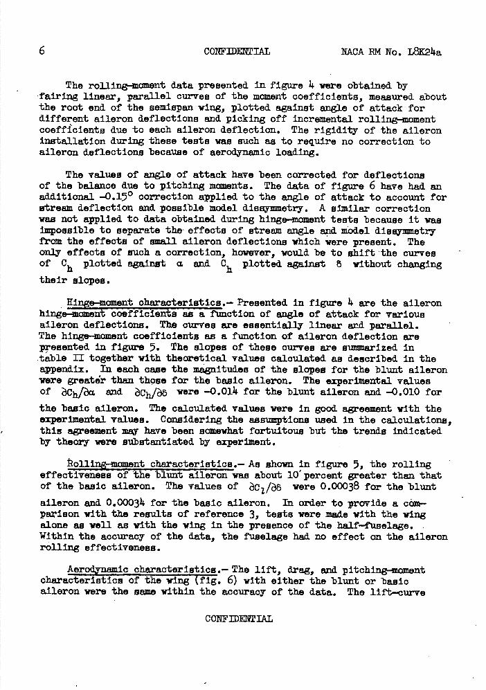
The rolling.-cmient data presented in figure 4 were obtained by fairing linear, parallel curves of the moment coefficients, measured about the root end of the semispan wing, plotted against angle of attack for different aileron deflections and picking off incremental rolling-moment coefficients due to each aileron deflection. The rigidity of the aileron installation during these tests was such as to require no correction to aileron deflections because of aerodynamic loading.
The values of angle of attack have been corrected for deflections of the balance due to pitching moments. The data of figure 6 have had an additional -0.150 correction applied to the angle of attack to account for stream deflection and possible model dissymmetry. A similar correction was not applied to data obtained during hinge-moment tests because it was impossible to separate the' effects of stream angle and model dissymmetry from the effects of small aileron deflections which were present. The only effects of such a correction, however, would be to shift 'the curves of Ch plotted, against a. and 0h plotted against 8 without changing
their slopes.
Hinge-moment characteristics.- Presented in figure 4 are the aileron hinge--moment coefficients as a function of angle of attack for various aileron deflections • The curves are essentially linear and parallel. The hinge-moment coefficients as a function of aileron deflection are presented in figure 5. The slopes of these curves are summarized in table II together with theoretical values calculated as described in the appendix. In each cane the magnitudes of the elopes for the blunt aileron were greatr than those for the basic aileron. The experimental values Of Ch/a. and Ch/8 were -.0.014 for the blunt aileron and -0.010 for
the basic aileron. The calculated values were In good agreement with the experimental values. Considering the assuptione used in the calculations, this agreement may have been somewhat fortuitous but the trends indicated by theory were substantiated by experiment.
Rolling-moinent characteristics.- As shown in figure 5, the rolling effectiveness of the blunt aileron was about 10' percent greater than that of the basic aileron. The values of were 0.00038 for the blunt
aileron and 0.00034 for the basic aileron. In order to provide a corn-pazison with the results of reference 3, tests were made with the wing alone as well as with the wing in the presence of the half-fuselage. Within the accuracy of the data, the fuselage had no effect on the aileron rolling effectiveness.
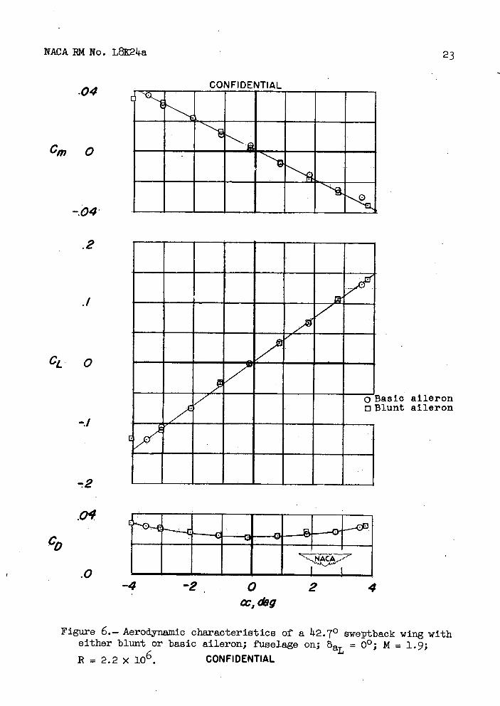
Aerodynamic characteristics.- The lift, drag, and pitching-moment characteristics of the wing fig. 6) with either the blunt or basic aileron were the same within the accuracy of the data. The lift-curve
CONFIDENTIAL

NPLCA PM No. L8E2 14a COW IDI1TIAL 7
Slope d.CL/d.a. of 0.037 would be increased, to 0.0144 if based on exposed
wing area and the theoretical lift-curve slope considering fuselage upwash was 0.0 11.7. This theoretical value was in better agreement with experiment than for the case of fuselage off where the theoretical dCL/d
was 0.0145 as compared with the experimental value of 0.040 (reference 3). The better agreement with theory of the wing in the presence of a fuselage probably was a result of smaller er boundary-layer effects at the wing-fuselage juncture than at the wing root when no fuselage was present.
CONCLUSIONS
From tests of basic and blunt ailerons on a 142.70 sveptback wing in the Langley 9— by 12-Inch supersonic blowd.own tunnel at a Mach number of 1.9, the following conclusions may be drawnl
(1)The rolling-tament coefficients of both ailerons varied approxi-mately linearly with aileron deflection, and the blunt aileron was about 10 percent more effective than the basic aileron.
(2)Hinge moments for both ailerons varied approximately linearly with both angle of atcaok and aileron deflection and were about 140 per-cent higher for the blunt aileron than for the basic aileron.
(3)Theoretically calculated. hinge 1ncmRnta were in good agreement with experimental results.
(14) There was no measurable difference in drag for the two wing-aileron combinations.
Langley Aeronautical Laboratory National Advisory Committee for Aeronautics
Langley Field, Va.
CONFIDENTIAL
8 CONFIDENTIAL NACA RM No. L8K2a
APPENDIX
METHOD OF CALCULATING HINGE MOMENTS
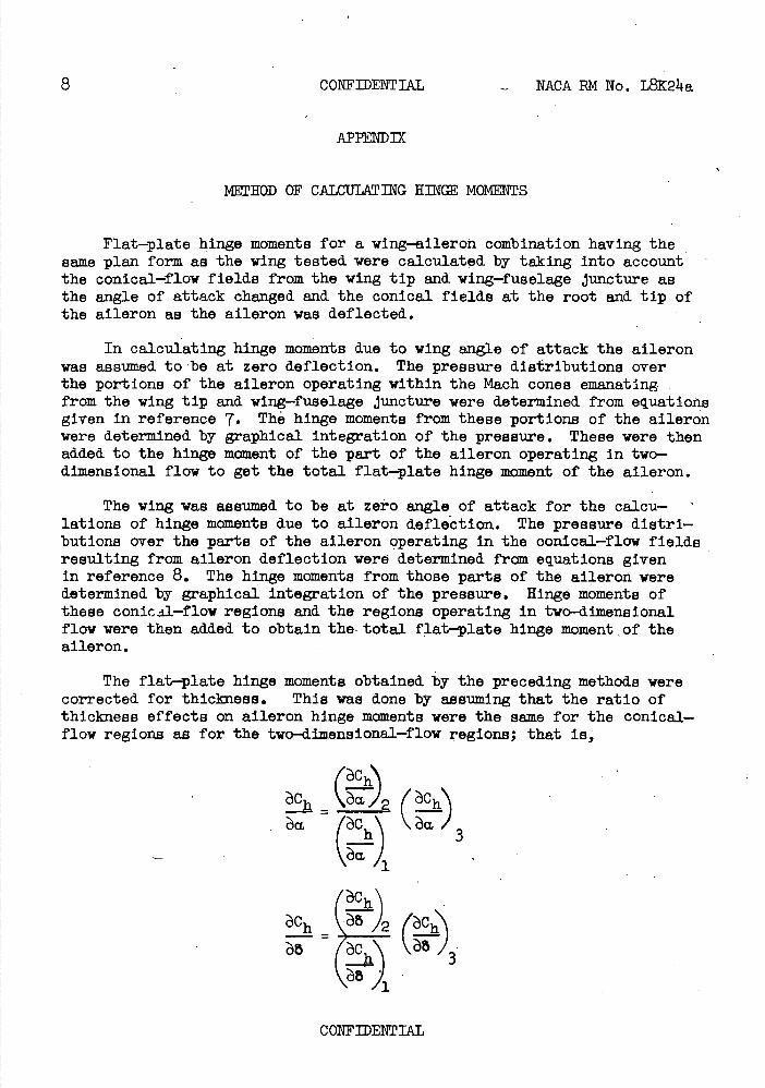
Flat-plate hinge moments for a wing-aileron combination having the seine plan form as the wing tested were calculated by taking into account the conical-flow fields from the wing tip and wing-fuselage Juncture as the angle of attack changed and the conical fields at the root and tip of the aileron as the aileron was deflected.
In calculating hinge moments due to wing angle of attack the aileron was assumed to 'be at zero deflection. The pressure distributions over the portions of the aileron operating within the Mach cones emanating from the wing tip and wing-fuselage juncture were determined from equations given in reference 1. The hinge momenta from these portions of the aileron were determined by graphical Integration of the pressure. These were then added to the hinge moment of the part of the aileron operating In two-dimensional flow to get the total flat-plate hinge moment of the aileron.
The wing was assumed to be at zero angle of attack for the calcu-lations of hinge moments due to aileron deflection. The pressure distri-butions over the parts of the aileron operating in the oonical-flow fields resulting from aileron deflection were determined from equations given in reference 8. The hinge moments from those parts of the aileron were determined by graphical integration of the pressure. Hinge moments of these conical-flow regions and the regions operating in two-dimensional flow were then added to obtain the total flat-plate hinge moment o± the aileron.
The flat-plate hinge moments obtained by the preceding methods were corrected for thickness. This was done by assuming that the ratio of thickness effects on aileron hinge moments were the seine for the conical-flow regions as for the two-dimensional-flow regions; that Is,
Ch Ga )
a.(•
.Sa/
(Ch'\
Ch (^Ch)
h 3
CONFIDENTIAL

NACA RN No. L8K24a CONFIDENTIAL 9
where the subscripts denote:
(i) Two-dimensional flat plate
(2) Three-dimensional flat plate
(3) Two-dimensional with thickness
Two-dimensions.], hinge moments considering thickness were calculated by using the "Buemann second-order approitnation theory" discussed in reference 9 ° This theory is limited to conditions where the shock wave at the leading edge of the airfoil Is attached to the airfoil. The wing for which the present calculations were made, however, had a half leading-edge angle in a plane normal to the leading edge which was larger than the angle at which a shock wave detaches for the Mach number component normal to the leading edge. It was assumed that the existing detached shock did not invalidate the theory used and consequently did not affect the calculated hinge moments.
In calculating hinge moments due to angle of attack, the Mach number component and aileron section contour in a plane normal to the wing leading edge were used. The Mach number component and aileron section contour in a plane normal'to the aileron hinge line were used in calcu-lating hinge moments due to aileron deflection.
Calculations, made by using the method previously discussed, give hinge moments which are in good agreement with experimental values. (See table II.) Table III gives a breakdown of calculated hinge moments.
CONFIDENTIAL

10 COI1F]DENTIAL NACA EM No. L824a
1. Sand.akl, Carl A.: Free-Flight Investigation at Transonic and Supersonic Speeds of the Rolling Effectiveness of a 42.70 Sweptback Wing Having Partial-Span Ailerons. NCA PM No. L8E25, 1948.
2. Turner, Thomas R. . Lockwood., Vernsrd. E., and. Vogler, Raymond D.: Preliminary Investigation of Various Ailerons on a420 Sweptback Wing for Lateral Control at Transonic Speeds. NACA EM No. L8D21, 1948.
3. Sivefls, James C., and Conner, D. William: Preliminary Investigation at a Mach number of 1.9 and. a Reynolds Number of 2,200,000 of Three Ailerons Applicable to the Bell XS-2 Airplane Design. NACA EM No. L8D02, 1948.
14 • Turner, Thomas R., Lockwood., Vernard. E., and Vogler, Raymond. D.: Aerodynamic Characteristics at Subsonic and Transonic Speeds of a 112.70 Sweptback Wing Model Having an Aileron with Finite Trailing-Edge Thickness. NA.CA PM No. L8K02, 1948.
5. Sand.ahl, Carl A.,: Free-Flight Thvestiga1ion at Transonic and SUDOThOfl.iC
Speeds of the Rolling Effectiveness of Several Aileron Configurations on a Tapered. Wing Having 112.70 Sveepback. NACA EM No. L8K23, 1948.
6. Conner, D • William: Aerodynamic Characteristics of Two All-Movable Wings Tested. In the Presence of a Fuselage at a Mach Number of 1.9. NA.CA PM No. L8UOI4, 1948.
7. Lageretroin, P. A., Wall, D., and Graham, M. E.: Formulas in Three-Dimensional Wing Theory. Rep. No. SM-11901, Douglas Aircraft Co., Inc., Aug., 1946.
8. Lagerstrom, P. A., and Graham, Martha E.: Linearized. Theory of Sixperaonic Control Surfaces. Rep. No. •SM-l3060, Douglas Aircraft Co., Inc., July 211, 1947.
9. Morrissette, Robert B., and Oborny, Lester F.: Theoretical Charac-teristics of Two-Dimensional Supersonic Control Surfaces. NACA EM No. 18G12, 1948.
CONFIDENTIAL

NACA RN No. L8K24a CONFIDENTIAL 11
TABLE I
ORDINATES FOR AIRFOIL SECTION OF 42.70 SWEPTBACK TAPERED WING
[Statione and ordinates given in percent airfoil chord in free—stream direction; section sym-metrical about chord line.]
Station Ordinate
0 0 5 .712
10 1.357 15 1.935 20 2.14 25 2.8811. 30 3.253 35 3.5149 14.0 3.772 11.5 3.919 50 3.989 55 3.981 60 3.892 65 3.720 70 3.11.63 75 3.120 80 2.686 85 2.161 90 1.5110 95 .821
100 0
CONFIDENTIAL

12 COTIFIDIAL NACA RN No. L8K24a
TABLE U
CEARA(Y]KR]ICS FOR BASIC AND BLOT AIIERO!B
Basic Blunt
?)Oxp .
('\ J —.oi6
—.010 —.011i
exp.
)Oal.—.009 —.013
CONFIDENTIAL

CONFIDENTIAL
1 o
UD (0
N- ON H 0 .
N- U\ H 0 .
H \O H 0
CU H 0
C.) (0 I I I
H
-
rn
CUccoo LC\
HCU H CU
I.
N-H
I•.
4)
N- N- "0 CU '-1 O\
iiH 0
H 0 H
0 8 o 4 C.) C I I I • /0 H •1-4
cd
C) -ri c
\o ",j
0\H 0
U\ m
H 0
0 0 r1 0 . b
.I• C.) /0
I•
C C .
4) H C) .c •1-4 4) '-1 P4 43 43
H
V Cl)
1:1
-1
0
H
N
E-4
C.)
pp
NACA PM No. L8K24a CONFIDENTIAL 13

Page intentionally left blank
/ 11
Page intentionally left blank

-J
I—z Ui C U-z 0 0
U)
cd H U) U)
C) UI
P-_g
z o ui
(\J LL.
0 C()
Pi UI
0 +) 0
H
ci)
QD
NACA RN No. L84a

NACA RM No. L8K24a 17
0009
- 0909 k-' L5'. _____ -21-16?
I I H 062 - _______ 0
fr9ooV0 -
r Cj_
I 0
o •T-la)
0
w o
2 o -
hLN 0
I "N irdrJ
H4
fr 00
Pi
acO 0
U 1 0
a) N-
II
.. I
1% C
_ H 0 . .
H
wqg cao
- I
Cu
a)
r1
iz PIN

NACA RM No. L8K2a
19
aj H P,
0 C-)
C)
0 N-
oJ -4-
b—i
r. 4
z 4w
ii QZ
I
I ci)
—J 4
I—z Ui
U-z 0 0

.1
Ch 0
-.1
-2
aa
(deg)
-0.10
5.35
8.55
12.90
NACA RM No. L8K24a
.1
-I
CONFIDENTIAL:
21
8 - a (deg)
0.65
5.65
8.85
15.40
-2 .0 2. 4 tzy;q
(a) Basic aileron.
-2 0 2. 4
w., deg
(b) Blunt aileron.
Figure 4• Hinge-moment characteristics of basic and blunt ailerons on
a 42.70 sweptback wing; fuselage on; M = 1.9; R = 2.2 x 10⁶. CONFIDENTIAL

CONFIDENTIAL
22
0
oh
-2
NACA RM No. L8K24a
leron, fuselage on leron, fuselage on
3asjc Aileron
)fuselage on ifuselage off
004
cz
rt Aileron
i8elage on iselage off
.004
4 8 /2 16
Figure 5.—Characteristics of basic and blunt ailerons on a 2.70 swept—
back wine; a = 0 0; M = 1. 9; R = 2.2 >< 10 6.
CONFIDENTIAL
.2
.1
CL 0
-.1
-2
sic aileron unt aileron
NACA RM No. L8K24a 23
.04 MUL.N HAL
Cm 0
-.04
Co Lw -4 0 2 4
cc, dog
Figure 6.- Aerodynamic characteristics of a 42.7 sweptback wing with either blunt or basic aileron; fuselage on; baL = 00 ; M = 1.9; R = 2.2 x 10⁶ . CONFIDENTIAL