Embed Size (px)
Citation preview
PNACE" T H E C O R R O S I O N S O C I E T Y
NACE Standard TM0497-2002 Item No. 21231
Standard Test Method
Measurement Techniques Related to Criteria for Cathodic Protection on Underground or
Submerged Metallic Piping Systems
This NACE International standard represents a consensus of those individual members who have reviewed this document, its scope, and provisions. Its acceptance does not in any respect preclude anyone, whether he has adopted the standard or not, from manufacturing, marketing, purchasing, or using products, processes, or procedures not in conformance with this standard. Nothing contained in this NACE International standard is to be construed as granting any right, by implication or otherwise, to manufacture, sell, or use in connection with any method, apparatus, or product covered by Letters Patent, or as indemnifying or protecting anyone against liability for infringement of Letters Patent. This standard represents minimum requirements and should in no way be interpreted as a restriction on the use of better procedures or materials. Neither is this standard intended to apply in all cases relating to the subject. Unpredictable circumstances may negate the usefulness of this standard in specific instances. NACE International assumes no responsibility for the interpretation or use of this standard by other parties and accepts responsibility for only those official NACE International interpretations issued by NACE International in accordance with its governing procedures and policies which preclude the issuance of interpretations by individual volunteers.
Users of this NACE International standard are responsible for reviewing appropriate health, safety, environmental, and regulatory documents and for determining their applicability in relation to this standard prior to its use. This NACE International standard may not necessarily address all potential health and safety problems or environmental hazards associated with the use of materials, equipment, and/or operations detailed or referred to within this standard. Users of this NACE International standard are also responsible for establishing appropriate health, safety, and environmental protection practices, in consultation with appropriate regulatory authorities if necessary, to achieve compliance with any existing applicable regulatory requirements prior to the use of this standard.
CAUTIONARY NOTICE: NACE International standards are subject to periodic review, and may be revised or withdrawn at any time without prior notice. NACE International requires that action be taken to reaffirm, revise, or withdraw this standard no later than five years from the date of initial publication. The user is cautioned to obtain the latest edition. Purchasers of NACE International standards may receive current information on all standards and other NACE International publications by contacting the NACE International Membership Services Department, 1440 South Creek Drive, Houston, Texas 77084-4906 (telephone + I 281/228-6200).
Reaffirmed 2002-04-1 1 Approved 1997-12-22
NACE International 1440 South Creek Drive
Houston, Texas 77084-4906 + I 281/228-6200
ISBN 1-57590-047-5 02002. NACE International
COPYRIGHT NACE InternationalLicensed by Information Handling ServicesCOPYRIGHT NACE InternationalLicensed by Information Handling Services
TM0497-2002
Foreword
This NACE International standard test method provides descriptions of the measurement techniques and cautionary measures most commonly used on underground piping to determine whether a specific criterion has been complied with at a test site. This test method includes only those measurement techniques that relate to the criteria or special conditions, such as a net protective current, contained in NACE Standard RP0169.’ This test method is intended for use by corrosion control personnel concerned with the corrosion of buried underground or submerged piping systems, including oil, gas, water, and similar structures.
The measurement techniques described require that the measurements be made in the field. Because the measurements are obtained under widely varying circumstances of field conditions and pipeline design, this standard is not as prescriptive as those NACE standard test methods that use laboratory measurements. Instead, this standard gives the user latitude to make testing decisions in the field based on the technical facts available.
This standard contains instrumentation and general measurement guidelines. It includes methods for voltage drop considerations when making pipe-to-electrolyte potential measurements and provides guidance to prevent incorrect data from being collected and used.
The measurement techniques provided in this standard were compiled from information submitted by committee members and others with expertise on the subject. Variations or other techniques not included may be equally effective. The complexity and diversity of environmental conditions may require the use of other techniques.
Appendix A contains information on the common types, use, and maintenance of reference electrodes. Appendix B contains information for the net protective current technique, which, while not a criterion, is a useful technique to reduce corrosion. Appendix C contains information regarding the use of coupons to evaluate cathodic protection. While some engineers use these techniques, they are not universally accepted practices. However, there is ongoing research into their use.
The test methods in this standard were originally prepared by NACE Task Group T-10A-3 on Test Methods and Measurement Techniques Related to Cathodic Protection Criteria, a component of Unit Committee T-1OA on Cathodic Protection. It was reviewed by Task Group 020 and reaffirmed in 2002 by Specific Technology Group (STG) 35 on Pipelines, Tanks, and Well Casings. This standard is issued by NACE under the auspices of STG 35.
In NACE standards, the terms shall, must, should, and may are used in accordance with the definitions of these terms in the NACE Publications Style Manual, 4th ed., Paragraph 7.4.1.9. Shall and must are used to state mandatory requirements. Should is used to state that which is considered good and is recommended but is not absolutely mandatory. May is used to state that which is considered optional.
NACE International I
COPYRIGHT NACE InternationalLicensed by Information Handling ServicesCOPYRIGHT NACE InternationalLicensed by Information Handling Services
TM0497-2002
1. 2. 3. 4. 5. 6. 7. 8.
9.
10
NACE International Stand a rd
Test Method
Measurement Techniques Related to Criteria for Cathodic Protection on Underground or Submerged Metallic Piping Systems
Contents
General.. ......................................... .......................................................... 1 Definitions ....................................... .......................................................... 1 Safety Considerations ............................................................ Instrumentation and M Pipe-to-Electrolyte Potential Measurements .......................... Causes of Measurement Errors .............................................
Test Method l-Negative 850 mV Pipe-to-Electrolyte Potential
Test Method 2-Negative 850 mV Polarized Pipe-to-Electrolyte Potential of Steel and Cast Iron Piping ....................................................... Test Method 3-1 O0 mV Cathodic Polarization of Steel, Cast Iron, Aluminum, and Copper Piping .................
Gu idelines.. .........................................
Voltage Drops Other Than Across the Pipe MetallElectrolyte
of Steel and Cast Iron Piping With Cathodic Protection Applied ................................ 10
....................... 8
................ 17
.................................... 18 ....................................................... 19 y of Cathodic Protection ................. 25
References.. . ............................................................. Bibliography .............................................................. .................................... 17 Appendix A: Reference Electrodes .......................... Appendix B: Net Protective Current ..... Appendix C: Using Coupons to Determ Figures Figure 1 : Instrument Connection .......................................................... Figure 2: Pipe-to-Electrolyte Pot Figure 3: Cathodic Polarization Curves ........................................
Figure B2: Pipe-to-Electrolyte Potential Survey of a Figure B I : Surface Potential Survey ........................ .................................... 23
Noncathodically Protected Pipeline. ........................................................ 24
ii NACE International
COPYRIGHT NACE InternationalLicensed by Information Handling ServicesCOPYRIGHT NACE InternationalLicensed by Information Handling Services
TM0497-2002
Section 1: General
1 .I This standard provides testing procedures to comply 1.3 Special conditions in which a given test technique is with the requirements of a criterion at a test site on a buried ineffective or only partially effective sometimes exist. Such or submerged steel, cast iron, copper, or aluminum pipeline. conditions may include elevated temperatures, disbonded
dielectric or thermally insulating coatings, shielding, 1.2 The provisions of this standard shall be applied by bacterial attack, and unusual contaminants in the personnel who have acquired by education and related electrolyte. Deviation from this standard may be warranted practical experience the principles of cathodic protection of in specific situations. In such situations corrosion control buried and submerged metallic piping systems. personnel should be able to demonstrate that adequate
cathodic protection has been achieved.
Section 2: Definitions‘’’
Anode: The electrode of an electrochemical cell at which oxidation occurs. Electrons flow away from the anode in the external circuit. Corrosion usually occurs and metal ions enter the solution at the anode.
Cable: A bound or sheathed group of insulated conductors.
Cathode: The electrode of an electrochemical cell at which reduction is the principal reaction. Electrons flow toward the cathode in the external circuit.
Cathodic Disbondment: The destruction of adhesion between a coating and the coated sutface caused by products of a cathodic reaction.
Cathodic Polarization: The change of electrode potential in the active (negative) direction caused by current across the e lectrode/e lectrol yte i nte tface. See a Is0 Polarization.
Cathodic Protection: A technique to reduce the corrosion of a metal sutface by making that sutface the cathode of an electrochemical cell.
Cathodic Protection Coupon: A metal sample representing the pipeline at the test site, used for cathodic protection testing, and having a chemical composition approximating that of the pipe. The coupon size should be small to avoid excessive current drain on the cathodic protection system.
Coating: A liquid, liquefiable, or mastic composition that, after application to a sutface, is converted into a solid protective, decorative, or functional adherent film.
Conductor: A bare or insulated material suitable for carrying electric current.
Corrosion: The deterioration of a material, usually a metal, that results from a reaction with its environment.
Corrosion Potential (Ecorr): The potential of a corroding sutface in an electrolyte relative to a reference electrode under open-circuit conditions (also known as rest potential, open-circuit potential, or freely corroding potential).
Criterion: A standard for assessment of the effectiveness of a cathodic protection system.
Current Density: The current to or from a unit area of an electrode sutface.
Electrical Isolation: The condition of being electrically separated from other metallic structures or the environment.
Electrode: A conductor used to establish contact with an electrolyte and through which current is transferred to or from an electrolyte.
Electrode Potential: The potential of an electrode in an electrolyte as measured against a reference electrode. (The electrode potential does not include any resistance losses in potential in either the electrolyte or the external circuit. It represents the reversible work to move a unit charge from the electrode sutface through the electrolyte to the reference electrode.)
Electrolyte: A chemical substance containing ions that migrate in an electric field. (For the purpose of this standard, electrolyte refers to the soil or liquid, including contained moisture and other chemicals, next to and in contact with a buried or submerged metallic piping system.)
Foreign Structure: Any metallic structure that is not intended as part of a system under cathodic protection.
(I) Definitions in this section reflect common usage among practicing corrosion control personnel and apply specifically to how terms are used in this standard. As much as possible, these definitions are in accord with those in the “NACE Glossary of Corrosion-Related Terms” (Houston, TX: NACE).
NACE International 1
COPYRIGHT NACE InternationalLicensed by Information Handling ServicesCOPYRIGHT NACE InternationalLicensed by Information Handling Services
TM0497-2002
Free Corrosion Potential: See Corrosion Potential.
Galvanic Anode: A metal that provides sacrificial protection to another metal that is more noble when electrically coupled in an electrolyte. This type of anode is the current source in one type of cathodic protection.
Holiday: A discontinuity in a protective coating that exposes unprotected sutface to the environment.
Impressed Current: An electric current supplied by a device employing a power source that is external to the electrode system. (An example is direct current for cathodic protection.)
“Instant OW’ Potential: A measurement of a pipe-to- electrolyte potential made without perceptible delay following the interruption of cathodic protection.
Interference: Any electrical disturbance on a metallic structure as a result of stray current.
Is o lat i o n : See Electrical Isolation.
Long-Line Current: Current through the earth between an anodic and a cathodic area that returns along an underground metallic structure.
Long-Line Current Voltage Drop Error: That voltage drop error in the “ow’ potential that is caused by current flow in the soil due to potential gradients along the pipe sutface.
“OW’ or “On”: A condition whereby cathodic protection current is either turned off or on.
Pipe-to-Electrolyte Potential: The potential difference between the pipe metallic sutface and electrolyte that is measured with reference to an electrode in contact with the electrolyte. This measurement is commonly termed pipe-to- soil (PIS).
Pi pe-to-Soi I: See Pipe-to-Electrolyte Potential.
Polarization: The change from the open-circuit potential as a result of current across the electrodelelectrolyte intetface.
Polarized Potential: The potential across the structurelelectrolyte intetface that is the sum of the corrosion potential and the cathodic polarization.
Potential Gradient: A change in the potential with respect to distance, expressed in millivolts per unit of distance.
Protection Potential: A measured potential meeting the requirements of a cathodic protection criterion.
Reference Electrode: An electrode whose open-circuit potential is constant under similar conditions of
measurement, which is used for measuring the relative potentials of other electrodes.
Resistance to Electrolyte: The resistance of a structure to the surrounding electrolyte.
Reverse-Current Switch: A device that prevents the reversal of direct current through a metallic conductor.
Shielding: Preventing or diverting the cathodic protection current from its intended path to the structure to be p rotected .
Shorted Pipeline Casing: A casing that is in metallic contact with the carrier pipe.
Side Drain Potential: A potential gradient measured between two reference electrodes, one located over the pipeline and the other located a specified distance lateral to the direction of the pipe.
Sound Engineering Practices: Reasoning exhibited or based on thorough knowledge and experience, logically valid, and having true premises showing good judgment or sense in the application of science.
Stray Current: Current through paths other than the intended circuit.
Telluric Current: Current in the earth that results from geomagnetic fluctuations.
Test Lead: A wire or cable attached to a structure for connection of a test instrument to make cathodic protection potential or current measurements.
Voltage: An electromotive force or a difference in electrode potentials expressed in volts.
Voltage Drop: The voltage across a resistance according to Ohm’s Law.
Voltage Spiking: A momentary surging of potential that occurs on a pipeline when the protective current flow from an operating cathodic protection device is interrupted or applied. This phenomenon is the result of inductive and capacitive electrical characteristics of the system and may be incorrectly recorded as an “ow’ or “on” pipe-to-electrolyte potential measurement. This effect may last for several hundred milliseconds and is usually larger in magnitude near the connection of the cathodic protection device to the pipeline. An oscilloscope or similar instrument may be necessary to identify the magnitude and duration of the spiking.
Wire: A slender rod or filament of drawn metal. In practice, the term is also used for smaller gauge conductors (size 6 mm2 [No. 10 AWG”’] or smaller).
(’) American Wire Gauge (AWG).
2 NACE International
COPYRIGHT NACE InternationalLicensed by Information Handling ServicesCOPYRIGHT NACE InternationalLicensed by Information Handling Services
TM0497-2002
Section 3: Safety Considerations
3.1 Appropriate safety precautions, including the following, shall be observed when making electrical measurements.
3.1.1 Be knowledgeable and qualified in electrical safety precautions before installing, adjusting, repairing, removing, or testing impressed current cathodic protection equipment.
3.1.2 Use properly insulated test lead clips and terminals to avoid contact with unanticipated high voltage (HV). Attach test clips one at a time using a single-hand technique for each connection.
3.1.3 Use caution when long test leads are extended near overhead high-voltage alternating current (HVAC) power lines, which can induce hazardous voltages onto the test leads. High-voltage direct current (HVDC) power lines do not induce voltages under normal operation, but transient conditions may cause hazardous voltages.
3.1.3.1 Refer to NACE Standard RP01772 for additional information about electrical safety.
3.1.4 Use caution when making tests at electrical isolation devices. Before proceeding with further tests, use appropriate voltage detection instruments or voltmeters with insulated test leads to determine whether hazardous voltages may exist.
3.1.5 Avoid testing when thunderstorms are in the area. Remote lightning strikes can create hazardous voltage surges that travel along the pipe under test.
3.1.6 Use caution when stringing test leads across streets, roads, and other locations subject to vehicular and pedestrian traffic. When conditions warrant, use appropriate barricades, flagging, and/or flag persons.
3.1.7 Before entering, inspect excavations and confined spaces to determine that they are safe. Inspections may include shoring requirements for excavations and testing for hazardous atmospheres in confined spaces.
3.1.8 Observe appropriate electrical codes and applicable safety regulations.
Section 4: Instrumentation and Measurement Guidelines
4.1 Cathodic protection electrical measurements require (f) Instrument resolution; proper selection and use of instruments. Pipe-to-electrolyte (9) Ruggedness; potential, voltage drop, potential difference, and similar (h) Alternating current (AC) and radio frequency (RF) measurements require instruments that have appropriate signal rejection; and - voltage ranges. The user should know the capabiiities and (i) limitations of the equipment, follow the manufacturer’s instruction manual, and be skilled in the use of electrical instruments. Failure to select and use instruments correctly causes errors in cathodic protection measurements.
4.1.1 Analog instruments are usually specified in terms of input resistance or internal resistance. This is usually expressed as ohms per volt of full meter scale deflection.
4.1.2 Digital instruments are usually specified in terms of input impedance expressed as megaohms.
4.2 Factors that may influence instrument selection for field testing include:
(a) Input impedance (digital instruments); (b) Input resistance or internal resistance (analog instruments); (c) Sensitivity; (d) Conversion speed of analog-to-digital converters used in digital or data logging instruments; (e) Accuracy;
4.3
Temperature and/or climate limitations.
4.2.1 Some instruments are capable of measuring and processing voltage readings many times per second. Evaluation of the input wave-form processing may be required if an instrument does not give consistent resu Its.
4.2.2 Measurement of pipe-to-electrolyte potentials on pipelines affected by dynamic stray currents may require the use of recording or analog instruments to improve measurement accuracy. Dynamic stray currents include those from electric railway systems, HVDC transmission systems, mining equipment, and telluric currents.
Instrument Effects on Voltage Measurements
4.3.1 To measure pipe-to-electrolyte potentials accurately, a digital voltmeter must have a high input impedance (high internal resistance, for an analog instrument) compared with the total resistance of the measurement circuit.
NACE International 3
COPYRIGHT NACE InternationalLicensed by Information Handling ServicesCOPYRIGHT NACE InternationalLicensed by Information Handling Services
TM0497-2002
4.3.1.1 An input impedance of 10 megaohms or more should be sufficient for a digital meter. An instrument with a lower input impedance may produce valid data if circuit contact errors are considered. One means of making accurate measurements is to use a potentiometer circuit in an analog meter.
4.3.1.2 A voltmeter measures the potential across its terminals within its design accuracy. However, current flowing through the instrument creates measurement errors due to voltage drops that occur in all resistive components of a measurement circuit.
4.3.2 Some analog-to-digital converters used in digital
instrument may indicate only a portion of the input waveform and thus provide incorrect voltage indications.
and data logging instruments operate so fast that the 4.4
4.3.3 Parallax errors on an analog instrument can be minimized by viewing the needle perpendicular to the
face of the instrument on the centerline projected from the needle point.
4.3.4 The accuracy of potential measurements should be verified by using an instrument having two or more input impedances (internal resistance, for analog instruments) and comparing potential values measured using different input impedances. If the measured values are virtually the same, the accuracy is acceptable. Corrections need to be made if measured values are not virtually identical. Digital voltmeters that have a constant input impedance do not indicate a measurement error by changing voltage ranges. An alternative is to use a meter with a potentiometer circuit.
Instrument Accuracy
4.4.1 Instruments shall be checked for accuracy before use by comparing readings to a standard voltage cell, to another acceptable voltage source, or to another appropriate instrument known to be accurate.
Section 5: Pipe-to-Electrolyte Potential Measurements
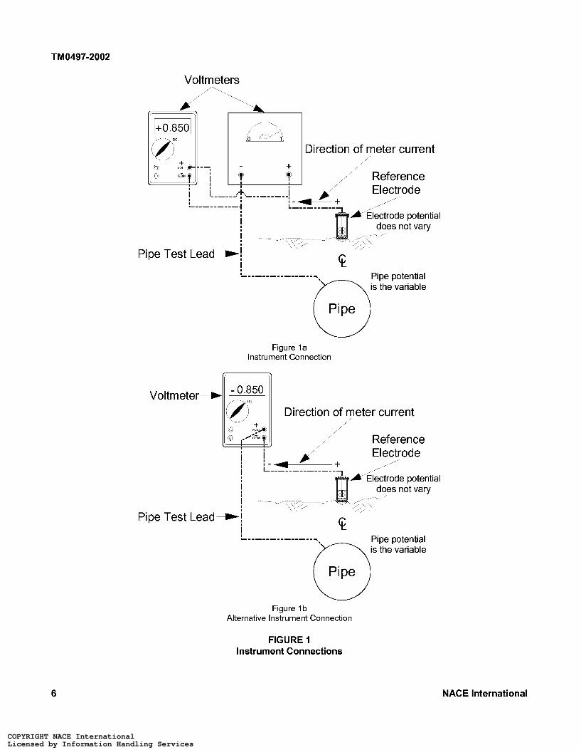
5.1 Instruments used to measure AC voltage, direct current (DC) voltage, or other electrical functions usually have one terminal designated “Common” (COM). This terminal either is black in color or has a negative (-) symbol. The positive terminal either is red in color or has a positive (+) symbol. The positive and negative symbols in the meter display indicate the current flow direction through the instrument (Figure la) . For example, a positive symbol in the meter display indicates current flowing from the positive terminal through the meter to the negative terminal. One instrument test lead is usually black in color and the other red. The black test lead is connected to the negative terminal of the instrument and the red lead to the positive terminal.
5.2 Voltage measurements should be made using the lowest practicable range on the instrument. A voltage measurement is more accurate when it is measured in the upper two-thirds of a range selected for a particular instrument. Errors can occur, for example, when an instrument with a 2-V range is used to measure a voltage of 15 mV. Such a value might be a voltage drop caused by current flowing in a metal pipeline or through a calibrated shunt. A much more accurate measurement would be made using an instrument having a 20-mV range.
5.3 The usual technique to determine the DC voltage across battery terminals, pipeline metal/electrolyte intetface, or other DC system is to connect the black test lead to the negative side of the circuit and the red test lead to the positive side of the circuit. When connected in this manner, an analog instrument needle moves in an upscale
(clockwise) direction indicating a positive value with relation to the negative terminal. A digital instrument connected in the same manner displays a digital value, usually preceded by a positive symbol. In each situation the measured voltage is positive with respect to the instrument‘s negative terminal. (See instrument connections in Figure la.)
5.4 The voltage present between a reference electrode and a metal pipe can be measured with a voltmeter. The reference electrode potential is normally positive with respect to ferrous pipe; conversely the ferrous pipe is negative with respect to the reference electrode.
5.5 A pipe-to-electrolyte potential is measured using a DC voltmeter having an appropriate input impedance (or internal resistance, for an analog instrument), voltage range(s), test leads, and a stable reference electrode, such as a saturated coppedcopper sulfate (CSE), silver/silver chloride (Ag/AgCI), or saturated potassium chloride (KCI) calomel reference electrode. The CSE is usually used for measurements when the electrolyte is soil or fresh water and less often for salt water. When a CSE is used in a high-chloride environment, the stability (lack of contamination) of the CSE must be determined before the readings may be considered valid. The Ag/AgCI reference electrode is usually used in seawater environments. The saturated KCI calomel electrode is used more often for laboratory work. However, more-rugged, polymer-body, gel-filled saturated KCI calomel electrodes are available, though modifications may be necessary to increase contact area with the environment.
4 NACE International
COPYRIGHT NACE InternationalLicensed by Information Handling ServicesCOPYRIGHT NACE InternationalLicensed by Information Handling Services
TM0497-2002
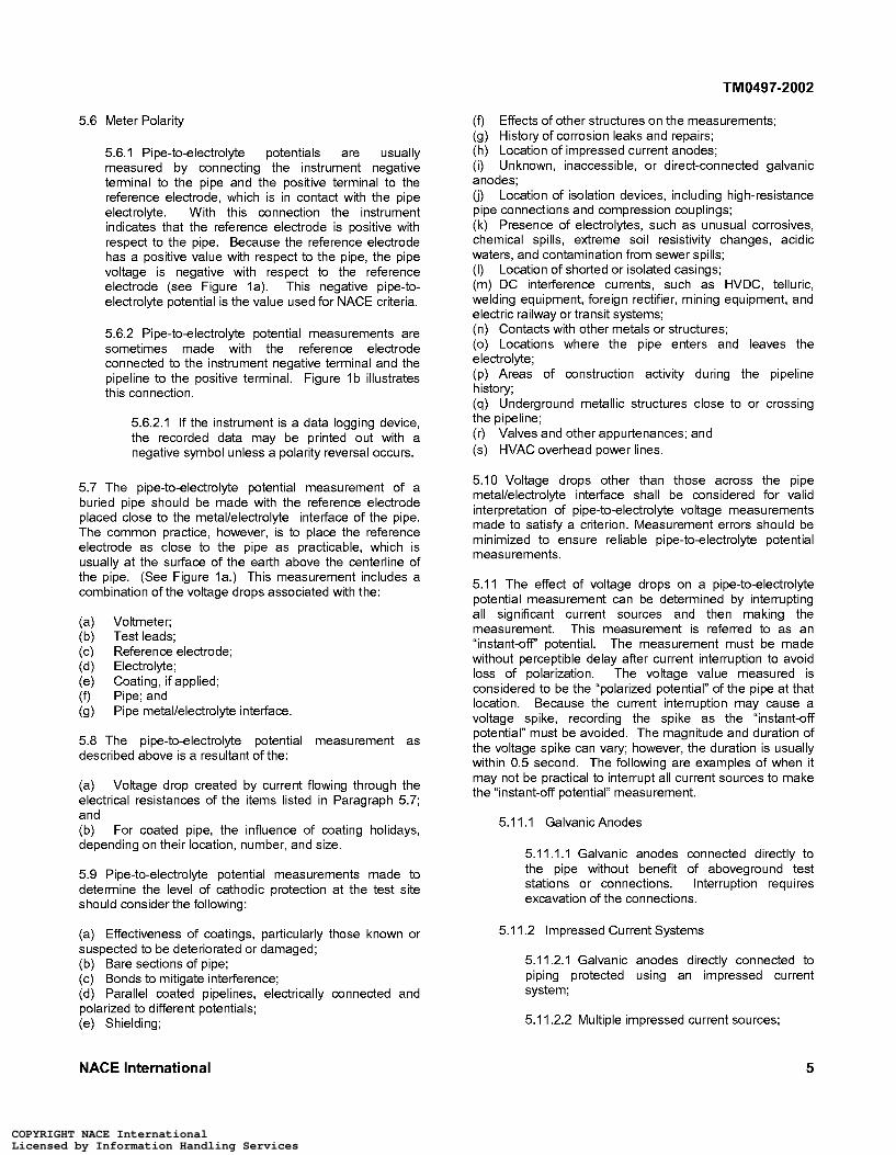
5.6 Meter Polarity
5.6.1 Pipe-to-electrolyte potentials are usually measured by connecting the instrument negative terminal to the pipe and the positive terminal to the reference electrode, which is in contact with the pipe electrolyte. With this connection the instrument indicates that the reference electrode is positive with respect to the pipe. Because the reference electrode has a positive value with respect to the pipe, the pipe voltage is negative with respect to the reference electrode (see Figure la). This negative pipe-to- electrolyte potential is the value used for NACE criteria.
5.6.2 Pipe-to-electrolyte potential measurements are sometimes made with the reference electrode connected to the instrument negative terminal and the pipeline to the positive terminal. Figure 1 b illustrates this connection.
5.6.2.1 If the instrument is a data logging device, the recorded data may be printed out with a negative symbol unless a polarity reversal occurs.
5.7 The pipe-to-electrolyte potential measurement of a buried pipe should be made with the reference electrode placed close to the metal/electrolyte intetface of the pipe. The common practice, however, is to place the reference electrode as close to the pipe as practicable, which is usually at the sutface of the earth above the centerline of the pipe. (See Figure la.) This measurement includes a combination of the voltage drops associated with the:
(a) Voltmeter; (b) Test leads; (c) Reference electrode; (d) Electrolyte; (e) Coating, if applied; (f) Pipe; and (9) Pipe metal/electrolyte intetface.
5.8 The pipe-to-electrolyte potential measurement as described above is a resultant of the:
(a) Voltage drop created by current flowing through the electrical resistances of the items listed in Paragraph 5.7; and (b) For coated pipe, the influence of coating holidays, depending on their location, number, and size.
5.9 Pipe-to-electrolyte potential measurements made to determine the level of cathodic protection at the test site should consider the following:
(a) Effectiveness of coatings, particularly those known or suspected to be deteriorated or damaged; (b) Bare sections of pipe; (c) Bonds to mitigate intetference; (d) Parallel coated pipelines, electrically connected and polarized to different potentials; (e) Shielding;
(f) Effects of other structures on the measurements; (9) History of corrosion leaks and repairs; (h) Location of impressed current anodes; (i) Unknown, inaccessible, or direct-connected galvanic anodes; (j) Location of isolation devices, including high-resistance pipe connections and compression couplings; (k) Presence of electrolytes, such as unusual corrosives, chemical spills, extreme soil resistivity changes, acidic waters, and contamination from sewer spills; (I) Location of shorted or isolated casings; (m) DC intetference currents, such as HVDC, telluric, welding equipment, foreign rectifier, mining equipment, and electric railway or transit systems; (n) Contacts with other metals or structures; (o) Locations where the pipe enters and leaves the electrolyte; (p) Areas of construction activity during the pipeline history; (4) Underground metallic structures close to or crossing the pipeline; (r) Valves and other appurtenances; and (s) HVAC overhead power lines.
5.10 Voltage drops other than those across the pipe metal/electrolyte intetface shall be considered for valid interpretation of pipe-to-electrolyte voltage measurements made to satisfy a criterion. Measurement errors should be minimized to ensure reliable pipe-to-electrolyte potential measurements.
5.11 The effect of voltage drops on a pipe-to-electrolyte potential measurement can be determined by interrupting all significant current sources and then making the measurement. This measurement is referred to as an “instant-off” potential. The measurement must be made without perceptible delay after current interruption to avoid loss of polarization. The voltage value measured is considered to be the “polarized potential” of the pipe at that location. Because the current interruption may cause a voltage spike, recording the spike as the “instant-off potential” must be avoided. The magnitude and duration of the voltage spike can vary; however, the duration is usually within 0.5 second. The following are examples of when it may not be practical to interrupt all current sources to make the “instant-off potential” measurement.
5.1 1 . I Galvanic Anodes
5.11.1.1 Galvanic anodes connected directly to the pipe without benefit of aboveground test stations or connections. Interruption requires excavation of the connections.
5.1 1.2 Impressed Current Systems
5.1 1.2.1 Galvanic anodes directly connected to piping protected using an impressed current system;
5.1 1.2.2 Multiple impressed current sources;
NACE International 5
COPYRIGHT NACE InternationalLicensed by Information Handling ServicesCOPYRIGHT NACE InternationalLicensed by Information Handling Services
TM0497-2002
a 63 "&A@
Voltmeters
Direction of meter current /
Direction of meter current
Reference
! I
- \\'b
Pipe Test Lead-! 6 c ! Pipe potential iT\ s the variable
' -__-__-__-__-__ ~
Pipe
Figure l a Instrument Connection
Reference Electrode
I
Voltmeter +
6 Pipe Test Lead-! +
I pi pe potential is the variable
Pipe Ld Figure 1 b
Alternative Instrument Connection
FIGURE 1 Instrument Connections
6 NACE International
COPYRIGHT NACE InternationalLicensed by Information Handling ServicesCOPYRIGHT NACE InternationalLicensed by Information Handling Services
TM0497-2002
5.1 1.2.3 Impressed current devices on foreign piping; and
5.1 1.2.4 Numerous cross bonds to parallel pipelines.
5.1 1.3 Natural and Manmade Stray Currents
5.1 1.3.1 Telluric currents; and
5.11.3.2 Manmade DC stray currents, such as those from mass transit and mining operations.
5.12 When voltage drops have been evaluated at a test location and the pipe-to-electrolyte potential found to be satisfactory, the “on” pipe-to-electrolyte potential value may be used for monitoring until significant environmental, structural, or cathodic protection system parameters change.
5.12.1 Significant environmental, structural, or cathodic protection system parameter changes may include:
(a) Replacement or addition of piping; (b) Addition, relocation, or deterioration of cathodic protection systems; (c) Failure of electrical isolating devices; (d) Effectiveness of coatings; and (e) Influence of foreign structures.
5.13 After a cathodic protection system is operating, time may be required for the pipe to polarize. This should be considered when measuring the potential at a test site on a newly protected pipe or after reenergizing a cathodic protection device.
Section 6: Causes of Measurement Errors
6.1 Factors that contribute to faulty potential measurements include:
6.1.1 Pipe and instrument test leads
(a) Broken or frayed wire strands (may not be visible inside the insulation); (b) Damaged or defective test lead insulation that allows the conductor to contact wet vegetation, the electrolyte, or other objects; (c) Loose, broken, or faulty pipe or instrument connections; and (d) Dirty or corroded connection points.
6.1.2 Reference electrode condition and placement
(a) Contaminated reference electrode solution or rod, and solutions of insufficient quantity or saturation (only laboratory-grade chemicals and distilled water, if water is required, should be used in a reference electrode); (b) Reference electrode plug not sufficiently porous to provide a conductive contact to the electrolyte; (c) Porous plug contaminated by asphalt, oil, or other foreign materials; (d) High-resistance contact between reference electrode and dry or frozen soil, rock, gravel, vegetation, or paving material; (e) Reference electrode placed in the potential gradient of an anode; (f) Reference electrode positioned in the potential gradient of a metallic structure other than the one with the potential being measured; (9) Electrolyte between pipe and disbonded coating causing error due to electrode placement in electrolyte on opposite side of coating;
(h) Defective permanently installed reference electrode; (i) Temperature correction not applied when needed; and (j) Photo-sensitive measurement error (in CSE with a clear-view window) due to light striking the electrode electrolyte solution (photovoltaic effect).
6.1.3 Unknown isolating devices, such as unbonded tubing or pipe compression fittings, causing the pipe to be electrically discontinuous between the test connection and the reference electrode location.
6.1.4 Parallel path inadvertently established by test personnel contacting instrument terminals or metallic parts of the test lead circuit, such as test lead clips and reference electrodes, while a potential measurement is being made.
6.1.5 Defective or inappropriate instrument, incorrect voltage range selection, instrument not calibrated or zeroed, or a damp instrument sitting on wet earth.
6.1.6 Instrument having an analog-to-digital converter operating at such a fast speed that the voltage spikes produced by current interruption are indicated instead of the actual “on” and “ow’ values.
6.1.7 Polarity of the measured value incorrectly observed.
6.1.8 Cathodic protection current-carrying conductor used as a test lead for a pipe potential measurement.
NACE International 7
COPYRIGHT NACE InternationalLicensed by Information Handling ServicesCOPYRIGHT NACE InternationalLicensed by Information Handling Services
TM0497-2002
6.2
7.1
6.1.9 Intetference
6.1.9.1 Electromagnetic intetference or induction resulting from AC power lines or radio frequency transmitters inducing test lead and/or instrument errors. This condition is often indicated by a fuzzy, fluctuating, or blurred pointer movement on an analog instrument or erratic displays on digital voltmeters. A DC voltmeter must have sufficient AC rejection capability, which can be determined by referring to the manufacturer's specification.
6.1.9.2 Telluric or stray DC currents flowing through the earth and piping.
Reference electrode contact resistance is reduced by:
6.2.1 Soil moisture-If the surface soil is so dry that the electrical contact of the reference electrode with the
electrolyte is impaired, the soil around the electrode may be moistened with water until the contact is adequate.
6.2.2 Contact sutface area-Contact resistance may be reduced by using a reference electrode with a larger contact surface area.
6.2.3 Frozen soil-Contact resistance may be reduced by removing the frozen soil to permit electrode contact with unfrozen soil.
6.2.4 Concrete or asphalt-paved areas-Contact resistance may be reduced by drilling through the paving to permit electrode contact with the soil.
Section 7: Voltage Drops Other Than Across the Pipe MetallElectrolyte Interface
Voltage drops that are present when pipe-to-electrolyte potential measurements are made occur in the following:
7.1 . I Measurement Circuit-The voltage drop other than across the pipe metal/electrolyte intetface in the measurement circuit is the sum of the individual voltage drops caused by the meter current flow through individual resistances that include:
(a) (b) Reference electrode internal resistance; (c) Reference e lectrode-to-electro I yte co ntact resistance; (d) Coating resistance; (e) Pipe metallic resistance; (f) Electrolyte resistance; (9) (h) Digital meter internal impedance. A measurement error occurs if the analog meter internal resistance or the digital meter internal impedance is not several orders of magnitude higher than the sum of the other resistances in the measurement circuit.
Instrument test lead and connection resistances;
Analog meter internal resistance; and
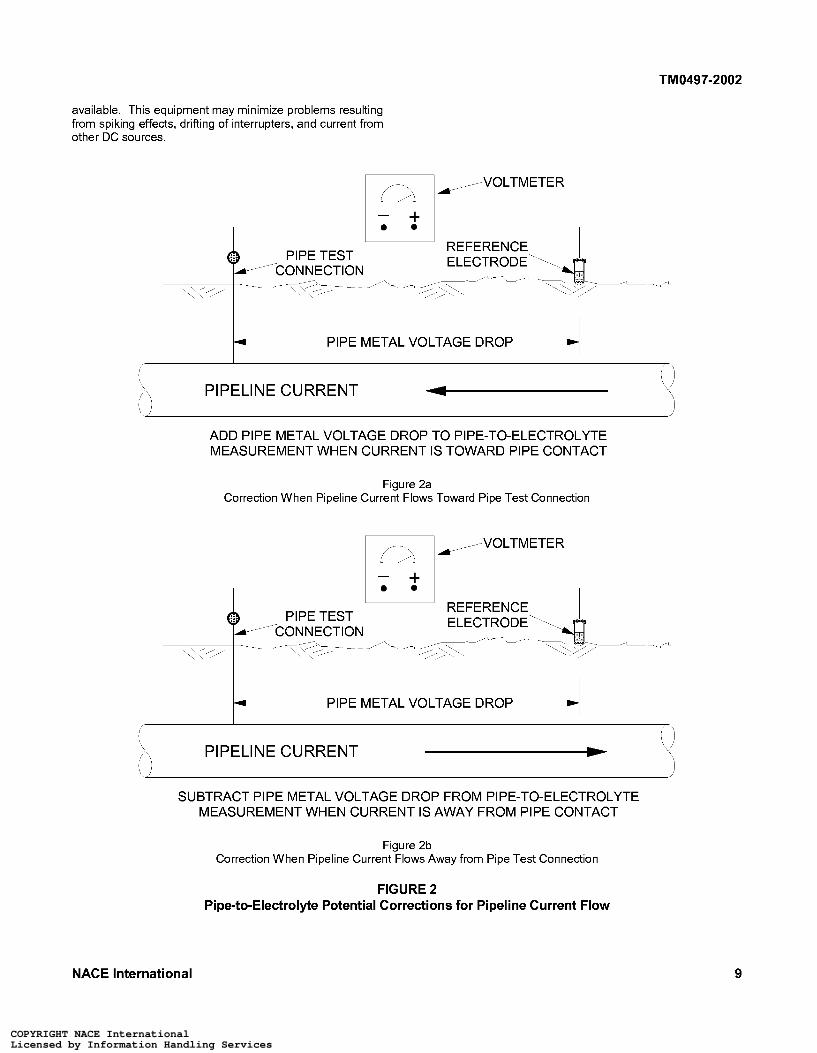
7.1.2 Pipe-Current flowing within the pipe wall creates a voltage drop. This voltage drop and the direction of the current shall be considered when the reference electrode is not near the pipe connection and significant current is conducted by the pipe. Consideration is needed because an error in the pipe- to-electrolyte potential measurement will occur if the pipe current causes a significant voltage drop. Current directed to the pipe connection from the reference electrode causes the measured potential to be more negative by the amount of the pipe current voltage drop (see Figure 2a). Conversely, the potential is less negative by that amount if the pipe current direction is
from the pipe connection to the reference electrode (see Figure 2b).
7.1.3 Electrolyte-When a pipe-to-electrolyte potential is measured with cathodic protection current applied, the voltage drop in the electrolyte between the reference electrode and the metal/electrolyte intetface shall be considered. Measurements taken close to sacrificial or impressed current anodes can contain a large voltage drop. Such a voltage drop can consist of, but is not limited to, the following:
(a) A voltage drop caused by current flowing to coating holidays when the line is coated; and (b) A voltage drop caused by large voltage gradients in the electrolyte that occur near operating anodes (sometimes termed "raised earth effect").
7.1.3.1 Testing to locate galvanic anodes by moving the reference electrode along the centerline of the line may be necessary when the locations are not known.
7.1.4 Coatings-Most coatings provide protection to the pipe by reducing the pipe sutface contact with the environment. Due to the relative ionic impermeability of coatings, they resist current flow. While the insulating ability of coatings reduces the current required for cathodic protection, coatings are not impervious to current flowing through them. Current flow through the coating causes a voltage drop that is greater than when the pipe is bare, under the same environmental conditions.
7.2 Specialized equipment that uses various techniques to measure the impressed current wave form and to calculate a pipe-to-electrolyte potential free of voltage drop is
8 NACE International
COPYRIGHT NACE InternationalLicensed by Information Handling ServicesCOPYRIGHT NACE InternationalLicensed by Information Handling Services
TM0497-2002
~
\\”/
available. This equipment may minimize problems resulting from spiking effects, drifting of interrupters, and current from other DC sources.
/CONNECTION
A
m/ VOLTMETER
4 -PIPE METAL VOLTAGE DROP
PIPELINE CURRENT
ADD PIPE METAL VOLTAGE DROP TO PIPE-TO-ELECTROLYTE MEASUREMENT WHEN CURRENT IS TOWARD PIPE CONTACT
Figure 2a Correction When Pipeline Current Flows Toward Pipe Test Connection
VOLTMETER m/
I- PIPE METAL VOLTAGE DROP 4 ‘.‘ PIPELINE CURRENT
SUBTRACT PIPE METAL VOLTAGE DROP FROM PIPE-TO-ELECTROLYTE MEASUREMENT WHEN CURRENT IS AWAY FROM PIPE CONTACT
Figure 2b Correction When Pipeline Current Flows Away from Pipe Test Connection
FIGURE 2 Pipe-to-Electrolyte Potential Corrections for Pipeline Current Flow
NACE International 9
COPYRIGHT NACE InternationalLicensed by Information Handling ServicesCOPYRIGHT NACE InternationalLicensed by Information Handling Services
TM0497-2002
Section 8: Test Method I-Negative 850 mV Pipe-to-Electrolyte Potential of Steel and Cast Iron Piping with Cathodic Protection Applied
8.1 Scope 8.3.2 Disadvantages
Test Method 1 describes a procedure to assess the adequacy of cathodic protection on a steel or cast iron pipeline according to the criterion stated in NACE Standard RPO 1 69, ’ Pa rag rap h 6.2.2.1 . I :
A negative (cathodic) potential of at least 850 mV with the cathodic protection applied. This potential is measured with respect to a saturated coppedcopper sulfate reference electrode (CSE) contacting the electrolyte. Voltage drops other than those across the structure-to-electrolyte boundary must be considered for valid interpretation of this voltage measurement.
NOTE: Consideration is understood to mean the application of sound engineering practice in determining the significance of voltage drops by methods such as:
(a) Potential measured includes voltage drops other than those across the pipe metallelectrolyte interface; and (b) Meeting the requirements for considering the significance of voltage drops (see Paragraph 8.6) can result in added time to assess adequacy of cathodic protection at the test site.
8.4 Basic Test Equipment
8.4.1 Voltmeter with adequate input impedance. Commonly used digital instruments have a nominal impedance of 10 megaohms. An analog instrument with an internal resistance of 100,000 ohms per volt may be adequate in certain circumstances in which the circuit resistance is low. A potentiometer circuit may be necessary in other instances.
(a) Measuring or calculating the voltage drop(s); 8.4.2 Two color-coded meter leads with clips for (b) Reviewing the historical performance of the connection to the pipeline and reference electrode. cathodic protection system; (c) Evaluating the physical and electrical 8.4.3 Reference Electrode characteristics of the pipe and its environment; and (d) Determining whether there is physical evidence of 8.4.3.1 CSE. corrosion.
8.2 General
8.2.1 Cathodic protection current shall remain “on” during the measurement process. This potential is commonly referred to as the “on” potential.
8.2.2 Test Method 1 measures the pipe-to-electrolyte potential as the sum of the polarized potential and any voltage drops in the circuit. These voltage drops include those through the electrolyte and pipeline coating from current sources such as impressed current, galvanic anodes, and telluric effects.
8.2.3 Because voltage drops other than those across the pipe metal/electrolyte interface may be included in this measurement, these drops shall be considered, as discussed in Paragraph 8.6.
8.3 Comparison with Other Methods
8.3.1 Advantages
8.4.3.2 Other standard reference electrodes may be substituted for the CSE. These reference electrodes are described in Appendix A, Paragraph A2.
8.5 Procedure
8.5.1 Before the test, verify that cathodic protection equipment has been installed and is operating properly. Time should be allowed for the pipeline potentials to reach polarized values.
8.5.2 Determine the location of the site to be tested. Selection of a site may be based on:
(a) Location accessible for future monitoring; (b) Other protection systems, structures, and anodes that may influence the pipe-to-electrolyte potential; (c) Electrical midpoints between protective devices; (d) Known location of an ineffective coating if the line is coated; and (e) Location of a known or suspected corrosive environment.
(a) Minimal equipment, personnel, and vehicles are 8.5.3 Make electrical contact between the reference required; and electrode and the electrolyte at the test site, directly (b) Less time is required to make measurements. over the centerline of the pipeline or as close to it as is
practicable.
10 NACE International
COPYRIGHT NACE InternationalLicensed by Information Handling ServicesCOPYRIGHT NACE InternationalLicensed by Information Handling Services
TM0497-2002
8.5.4 Connect the voltmeter to the pipeline and reference electrode as described in Paragraph 5.6.
8.5.5 Record the pipe-to-electrolyte potential and its polarity with respect to the reference electrode.
8.6 Considering the Significance of Voltage Drops for Valid Interpretation of the Criterion
8.6.1 The significance of voltage drops can be considered by:
8.6.1 . I Comparing historical levels of cathodic protection with physical evidence from the pipeline to determine whether corrosion has occurred.
8.6.1.2 Comparing soil corrosiveness with physical evidence from the pipeline to determine whether corrosion has occurred.
8.6.2 Physical evidence of corrosion is determined by evaluating items such as:
(a) Leak history data;
(b) Buried pipeline inspection report data regarding locations of coating failures, localized conditions of more-corrosive electrolyte, or substandard cathodic protection levels have been experienced; and/or (c) Verification of in-line inspection-tool metal loss indications by follow-up excavation of anomalies and inspection of the pipe external surface.
8.6.3 Cathodic protection shall be judged adequate at the test site if:
(a) The pipe-to-electrolyte potential measurement is negative 850 mV, or more negative, with respect to a CSE; and (b) The significance of voltage drops has been considered by applying the principles described in Paragraphs 8.6.1 or 8.6.2.
8.7 Monitoring
When the significance of a voltage drop has been considered at the test site, the measured potentials may be used for monitoring unless significant environmental, structural, coating integrity, or cathodic protection system parameters have changed.
Section 9: Test Method 2-Negative 850 mV Polarized Pipe-to-Electrolyte Potential of Steel and Cast Iron Piping
9.1 Test Method 2 describes the most commonly used test method to satisfy this criterion (see Paragraph 9.2). This method uses current interruption to determine whether cathodic protection is adequate at the test site according to the criterion.
9.2 Scope
This method uses an interrupter(s) to eliminate the cathodic protection system voltage drop from the pipe-to-electrolyte potential measurement for comparison with the criterion stated in NACE Standard RPOI 69,? Paragraph 6.2.2.1.2:
A negative polarized potential of at least 850 mV relative to a saturated coppedcopper sulfate reference electrode (CSE).
9.3 General
9.3.1 Interrupting the known cathodic protection current source(s) eliminates voltage drops associated with the protective currents being interrupted. However, significant voltage drops may also occur because of currents from other sources, as discussed in Section 7.
9.3.2 To avoid significant depolarization of the pipe, the ?ow? period should be limited to the time necessary
to make an accurate potential measurement. The ?ow? period is typically less than 3 seconds.
9.3.3 The magnitude and duration of a voltage spike caused by current interruption can vary, but the duration is typically within 0.5 second. After the current is interrupted, the time elapsed until the measurement is recorded should be long enough to avoid errors caused by voltage spiking. On-site measurements with appropriate instruments may be necessary to determine the duration and magnitude of the spiking.
9.3.4 Current sources that can affect the accuracy of this test method include the following:
(a) Unknown, inaccessible, or direct-connected galvanic anodes; (b) Cathodic protection systems on associated piping or foreign structures; (c) Electric railway systems; (d) HVDC electric power systems; (e) Telluric currents; (f) Galvanic, or bimetallic, cells; (9) DC mining equipment; (h) and polarized to different potentials; (i) Uninterrupted current sources; (j) Unintentional connections to other structures or bonds to mitigate interference; and (k) Long-line currents.
Parallel coated pipelines, electrically connected
NACE International 11
COPYRIGHT NACE InternationalLicensed by Information Handling ServicesCOPYRIGHT NACE InternationalLicensed by Information Handling Services
TM0497-2002
9.4 Comparison with Other Methods
9.4.1 Advantages
(a) Voltage drops associated with the protective currents being interrupted are eliminated.
9.4.2 Disadvantages
(a) Additional equipment is required; (b) Additional time, personnel, and vehicles may be required to set up equipment and to make pipe-to- electrolyte potential measurements; and (c) Test results are difficult or impossible to analyze when stray currents are present or direct-connected galvanic anodes or foreign impressed current devices are present and cannot be interrupted.
9.5 Basic Test Equipment
9.5.1 Voltmeter with adequate input impedance. Commonly used digital instruments have a nominal impedance of 10 megaohms. An analog instrument with an internal resistance of 100,000 ohms per volt may be adequate in certain circumstances in which the circuit resistance is low. A potentiometer circuit may be necessary in other instances.
9.5.2 Two color-coded meter leads with clips for connection to the pipeline and reference electrode.
9.5.3 Sufficient current interrupters to interrupt influential cathodic protection current sources simultaneously.
9.5.4 Reference electrode
9.5.4.1 CSE.
9.5.4.2 Other standard reference electrodes may be substituted for the CSE. These reference electrodes are described in Appendix A, Paragraph A2.
9.6 Procedure
9.6.1 Before the test, verify that cathodic protection equipment has been installed and is operating properly. Time should be allowed for the pipeline potentials to reach polarized values.
protecting the pipe at the test site, and place in operation with a synchronized and/or known “ow’ and “on” cycle. The “ow’ cycle should be kept as short as possible but still long enough to read a polarized pipe- to-electrolyte potential after any “spike” as shown in Figure 3a has collapsed.
9.6.3 Determine the location of the site to be tested. Selection of a site may be based on:
(a) Location accessible for future monitoring; (b) Other protection systems, structures, and anodes that may influence the pipe-to-electrolyte potential; (c) Electrical midpoints between protection devices; (d) Known location of an ineffective coating when the pipeline is coated; and (e) Location of a known or suspected corrosive environ me nt .
9.6.4 Make electrical contact between the reference electrode and the electrolyte at the test site, directly over the centerline of the pipeline or as close to it as is practicable.
9.6.5 Connect voltmeter to the pipeline and reference electrode as described in Paragraph 5.6.
9.6.5.1 If spiking may be present, use an appropriate instrument, such as an oscilloscope or high-speed recording device, to verify that the measured values are not influenced by a voltage spike.
9.6.6 Record the pipe-to-electrolyte “on” and “ow’ potentials and their polarities with respect to the reference e led rode.
9.7 Evaluation of Data
Cathodic protection shall be judged adequate at the test site if the polarized pipe-to-electrolyte potential is negative 850 mV, or more negative, with respect to a CSE.
9.8 Monitoring
When the polarized pipe-to-electrolyte potential has been determined to equal or exceed a negative 850 mV, the pipeline “on” potential may be used for monitoring unless significant environmental, structural, coating integrity, or cathodic protection system parameters have changed.
9.6.2 Install and place in operation necessary interrupter equipment in all significant DC sources
12 NACE International
COPYRIGHT NACE InternationalLicensed by Information Handling ServicesCOPYRIGHT NACE InternationalLicensed by Information Handling Services
TM0497-2002
. . . . . . . . . . . . . . . . . . . . . . . . . . . . . . . . . . . . . . . . . . . . . . . . . . . . . . . . . . . . . . . . . . . . . . . .
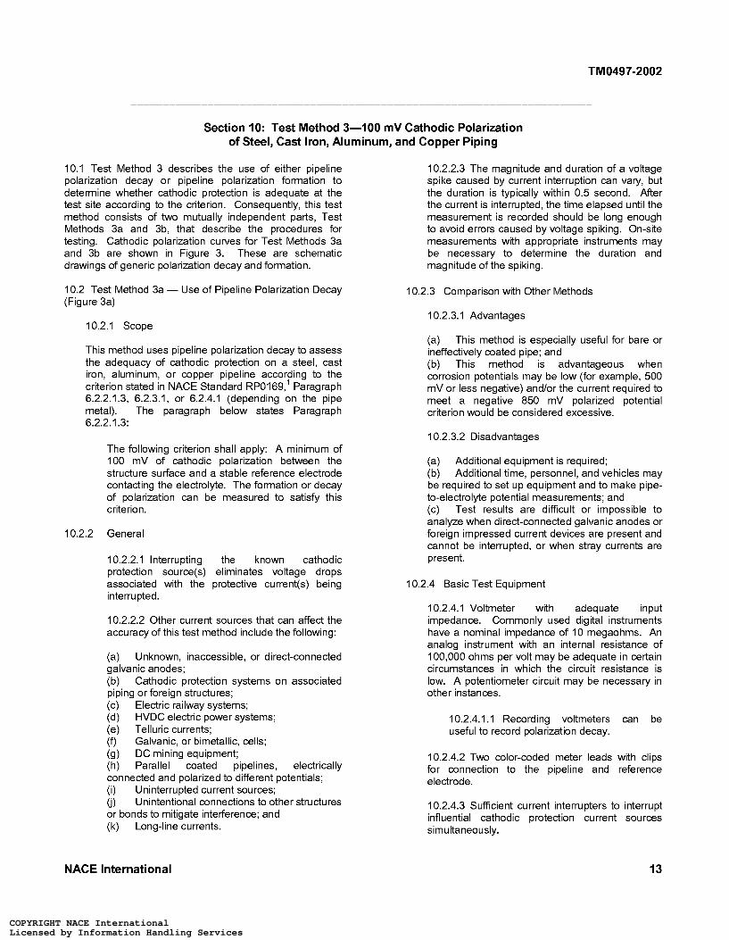
Section IO: Test Method 3-100 mV Cathodic Polarization of Steel, Cast Iron, Aluminum, and Copper Piping
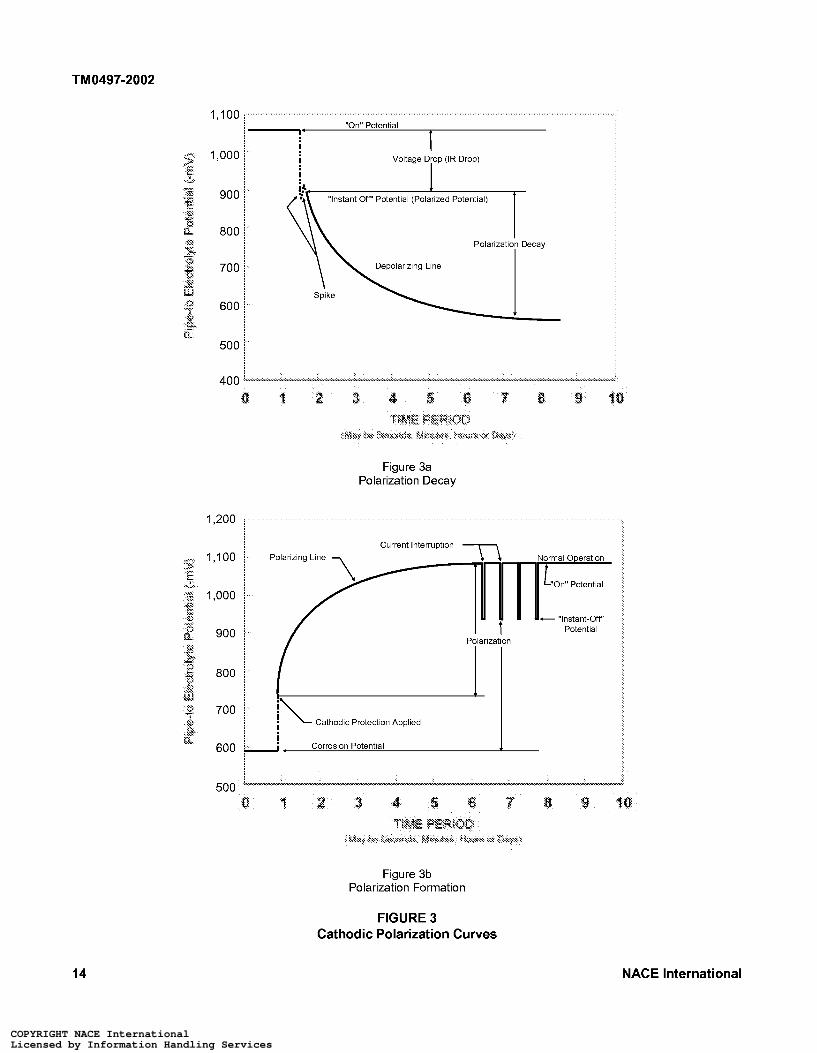
10.1 Test Method 3 describes the use of either pipeline polarization decay or pipeline polarization formation to determine whether cathodic protection is adequate at the test site according to the criterion. Consequently, this test method consists of two mutually independent parts, Test Methods 3a and 3b, that describe the procedures for testing. Cathodic polarization curves for Test Methods 3a and 3b are shown in Figure 3. These are schematic drawings of generic polarization decay and formation.
10.2 Test Method 3a - Use of Pipeline Polarization Decay (Figure 3a)
10.2.1 Scope
This method uses pipeline polarization decay to assess the adequacy of cathodic protection on a steel, cast iron, aluminum, or copper pipeline according to the criterion stated in NACE Standard RP0169,’ Paragraph 6.2.2.1.3, 6.2.3.1, or 6.2.4.1 (depending on the pipe metal). The paragraph below states Paragraph 6.2.2.1.3:
The following criterion shall apply: A minimum of 100 mV of cathodic polarization between the structure sutface and a stable reference electrode contacting the electrolyte. The formation or decay of polarization can be measured to satisfy this criterion.
10.2.2 General
10.2.2.1 Interrupting the known cathodic protection source(s) eliminates voltage drops associated with the protective current(s) being interrupted.
10.2.2.2 Other current sources that can affect the accuracy of this test method include the following:
(a) Unknown, inaccessible, or direct-connected galvanic anodes; (b) Cathodic protection systems on associated piping or foreign structures; (c) Electric railway systems; (d) HVDC electric power systems; (e) Telluric currents; (f) Galvanic, or bimetallic, cells; (9) DC mining equipment; (h) Parallel coated pipelines, electrically connected and polarized to different potentials; (i) Uninterrupted current sources; (j) or bonds to mitigate intetference; and (k) Long-line currents.
Unintentional connections to other structures
10.2.2.3 The magnitude and duration of a voltage spike caused by current interruption can vary, but the duration is typically within 0.5 second. After the current is interrupted, the time elapsed until the measurement is recorded should be long enough to avoid errors caused by voltage spiking. On-site measurements with appropriate instruments may be necessary to determine the duration and magnitude of the spiking.
10.2.3 Comparison with Other Methods
10.2.3.1 Advantages
(a) This method is especially useful for bare or ineffectively coated pipe; and (b) This method is advantageous when corrosion potentials may be low (for example, 500 mV or less negative) and/or the current required to meet a negative 850 mV polarized potential criterion would be considered excessive.
10.2.3.2 Disadvantages
(a) Additional equipment is required; (b) Additional time, personnel, and vehicles may be required to set up equipment and to make pipe- to-electrolyte potential measurements; and (c) Test results are difficult or impossible to analyze when direct-connected galvanic anodes or foreign impressed current devices are present and cannot be interrupted, or when stray currents are present.
10.2.4 Basic Test Equipment
10.2.4.1 Voltmeter with adequate input impedance. Commonly used digital instruments have a nominal impedance of 10 megaohms. An analog instrument with an internal resistance of 100,000 ohms per volt may be adequate in certain circumstances in which the circuit resistance is low. A potentiometer circuit may be necessary in other instances.
10.2.4.1 . I Recording voltmeters can be useful to record polarization decay.
10.2.4.2 Two color-coded meter leads with clips for connection to the pipeline and reference electrode.
10.2.4.3 Sufficient current interrupters to interrupt influential cathodic protection current sources simultaneously.
NACE International 13
COPYRIGHT NACE InternationalLicensed by Information Handling ServicesCOPYRIGHT NACE InternationalLicensed by Information Handling Services
TM0497-2002
1,100
1,000
900
800
700
600
500
400 Q
1,200
1,100
1,000
900
800
700
600
~ "On" Potential , ! ! !
Voltage Drop (IR Drop)
I 1
"Instant ow' Potential (Polarized Potential)
Polarization Decay
Depolarizing Line
Spike
Figure 3a Polarization Decay
Current Interruption 7
I i Corrosion Potential
c "Instant-ow' Potential
1
Figure 3b Polarization Formation
FIGURE 3 Cathodic Polarization Curves
14 NACE International
COPYRIGHT NACE InternationalLicensed by Information Handling ServicesCOPYRIGHT NACE InternationalLicensed by Information Handling Services
TM0497-2002
10.2.4.4 Reference electrode
10.2.4.4.1 CSE.
10.2.4.4.2 Other standard reference electrodes may be substituted for the CSE. These reference electrodes are described in Appendix A, Paragraph A2.
10.2.5 Procedure
10.2.5.1 Before the test, verify that cathodic protection equipment has been installed and is operating properly. Time should be allowed for the pipeline potentials to reach polarized values.
10.2.5.2 Install and place in operation necessary interrupter equipment in all significant DC sources protecting the pipe at the test site, and place in operation with a synchronized and/or known “ow’ and “on” cycle. The “ow’ cycle should be kept as short as possible but still long enough to read a polarized pipe-to-electrolyte potential after any “spike” as shown in Figure 3a has collapsed.
10.2.5.3 Determine the location of the site to be tested. Selection of a site may be based on:
(a) (b) Other protection systems, structures, and anodes that may influence the pipe-to-electrolyte potential; (c) Electrical midpoints between protection devices; (d) Known location of an ineffective coating if the pipeline is coated; and (e) Location of a known or suspected corrosive environment.
Location accessible for future monitoring;
10.2.5.4 Make electrical contact between the reference electrode and the electrolyte at the test site, directly over the centerline of the pipeline or as close to it as is practicable.
10.2.5.4.1 Identify the location of the electrode to allow it to be returned to the same location for subsequent tests.
10.2.5.5 Connect the voltmeter to the pipeline and reference electrode as described in Paragraph 5.6.
10.2.5.5.1 If spiking may be present, use an appropriate instrument, such as an oscilloscope or high-speed recording device, to verify that the measured values are not influenced by a voltage spike.
10.2.5.6 Measure and record the pipe-to- electrolyte “on” and “instant ow’ potentials and their polarities with respect to the reference electrode.
10.2.5.6.1 The “instant ow’ pipe-to-electrolyte potential is the “baseline” potential from which the polarization decay is calculated.
10.2.5.7 Turn off sufficient cathodic protection current sources that influence the pipe at the test site until at least 100 mV cathodic polarization decay has been attained.
10.2.5.7.1 Continue to measure and record the pipe-to-electrolyte potential until it either:
(a) Has become at least 100 mV less negative than the “ow’ potential; or (b) Has reached a stable depolarized level.
10.2.5.7.2 Measurements shall be made at sufficiently frequent intervals to avoid attaining and remaining at a corrosion potential for an unnecessarily extended period.
10.2.5.7.3 When extended polarization decay time periods are anticipated, it may be desirable to use recording voltmeters to determine when adequate polarization decay or a corrosion potential has been attained.
10.2.6 Evaluation of Data
Cathodic protection shall be judged adequate at the test site if 100 mV or more of polarization decay is measured with respect to a standard reference electrode.
10.2.7 Monitoring
When at least 100 mV or more of polarization decay has been measured, the pipeline “on” potential at the test site may be used for monitoring unless significant environmental, structural, coating integrity, or cathodic protection system parameters have changed.
10.3 Test Method 3b-Use of Pipeline Polarization Formation (Figure 3b)
10.3.1 Scope
This method provides a procedure using the formation of polarization to assess the adequacy of cathodic protection at a test site on steel, cast iron, aluminum, or copper piping according to the criteria stated in NACE Standard RPOI 69,’ Paragraphs 6.2.2.1.3, 6.2.3.1, or 6.2.4.1 (depending on the pipe metal). The paragraph below states Paragraph 6.2.2.1.3:
The following criterion shall apply: A minimum of 1 O0 mV of cathodic polarization between the structure sutface and a stable reference electrode contacting the electrolyte. The formation or decay of polarization can be measured to satisfy this criterion.
NACE International 15
COPYRIGHT NACE InternationalLicensed by Information Handling ServicesCOPYRIGHT NACE InternationalLicensed by Information Handling Services
TM0497-2002
10.3.2 General
Ferrous, aluminum, and copper pipelines may be adequately cathodically protected if applying cathodic protection causes a polarization change of 100 mV or more with respect to a reference potential.
10.3.2.1 Current sources that can affect the accuracy of this test method include the following:
(a) Unknown, inaccessible, or direct-connected galvanic anodes; (b) Cathodic protection systems on associated piping or foreign structures; (c) Electric railway systems; (d) HVDC electric power systems; (e) Telluric currents; (f) Galvanic, or bimetallic, cells; (9) DC mining equipment; (h) Parallel coated pipelines, electrically connected and polarized to different potentials; (i) Uninterrupted current sources; (j) or bonds to mitigate intetference; and (k) Long-line currents.
Unintentional connections to other structures
10.3.3 Comparison with Other Methods
10.3.3.1 Advantages
(a) This method is especially useful for bare or ineffectively coated pipe; and (b) This method is advantageous when corrosion potentials may be low (for example, 500 mV or less negative) and/or the current required to meet a negative 850 mV potential criterion would be considered excessive.
10.3.3.2 Disadvantages
(a) Additional equipment is required; (b) Additional time, personnel, and vehicles may be required to set up equipment and to make the pipe-to-electrolyte potential measurements; and (c) Test results are difficult or impossible to analyze when stray currents are present or when direct-connected galvanic anodes or foreign impressed currents are present and cannot be interrupted.
10.3.4 Basic Test Equipment
10.3.4.1 Voltmeter with adequate input impedance. Commonly used digital instruments have a nominal impedance of 10 megaohms. An analog instrument with an internal resistance of 100,000 ohms per volt may be adequate in certain circumstances in which the circuit resistance is low. A potentiometer circuit may be necessary in other instances.
10.3.4.2 Two color-coded meter leads with clips for connection to the pipeline and reference electrode.
10.3.4.3 Sufficient current interrupters to interrupt influential cathodic protection current sources simultaneously.
10.3.4.4 Reference electrode
10.3.4.4.1 CSE.
10.3.4.4.2 Other standard reference electrodes may be substituted for the CSE. These reference electrodes are described in Appendix A, Paragraph A2.
10.3.5 Procedure
10.3.5.1 Before the test, verify that cathodic protection equipment has been installed but is not operating .
10.3.5.2 Determine the location of the site to be tested. Selection of a site may be based on:
(a) (b) Other protection systems, structures, and anodes that may influence the pipe-to-electrolyte potential; (c) Electrical midpoints between protection devices; (d) Known location of an ineffective coating if the line is coated; and (e) Location of a known or suspected corrosive environment.
Location accessible for future monitoring;
10.3.5.3 Make electrical contact between the reference electrode and the electrolyte at the test site, directly over the centerline of the pipeline or as close to it as is practicable.
10.3.5.3.1 Identify the location of the electrode to allow it to be returned to the same location for subsequent tests.
10.3.5.4 Connect the voltmeter to the pipeline and reference electrode as described in Paragraph 5.6.
10.3.5.5 Measure and record the pipe-to- electrolyte corrosion potential and its polarity with respect to the reference electrode.
10.3.5.5.1 This potential is the value from which the polarization formation is calculated.
10.3.5.6 Apply the cathodic protection current. Time should be allowed for the pipeline potentials to reach polarized values.
16 NACE International
COPYRIGHT NACE InternationalLicensed by Information Handling ServicesCOPYRIGHT NACE InternationalLicensed by Information Handling Services
TM0497-2002
10.3.5.7 Install and place in operation necessary interrupter equipment in all significant DC sources protecting the pipe at the test site, and place in operation with a synchronized and/or known “ow’ and “on” cycle. The “ow’ cycle should be kept as short as possible but still long enough to read a polarized pipe-to-electrolyte potential after any “spike” as shown in Figure 3a has collapsed.
10.3.5.8 Measure and record the pipe-to- electrolyte “on” and “ow’ potentials and their polarities with respect to the reference electrode. The difference between the “ow’ potential and the corrosion potential is the amount of polarization formation.
10.3.5.8.1 If spiking may be present, use an appropriate instrument, such as an
oscilloscope or high-speed recording device, to verify that the measured values are not influenced by a voltage spike.
10.3.6 Evaluation of Data
Cathodic protection shall be judged adequate if 100 mV or more of polarization formation is measured with respect to a standard reference electrode.
10.3.7 Monitoring
When at least 100 mV or more of polarization formation has been measured, the pipeline “on” potential may be used for monitoring unless significant environmental, structural, coating integrity, or cathodic protection system parameters have changed.
References
1. NACE Standard RP0169 (latest revision), “Control of 3. F.J. Ansuini, J.R. Dimond, “Factors Affecting the External Corrosion on Underground or Submerged Metallic Accuracy of Reference Electrodes,” MP 33, 11 (1994), p. Piping Systems” (Houston, TX: NACE). 14.
2. NACE Standard RP0177 (latest revision), “Mitigation of 4. NACE Publication 35201 (latest revision), “Technical Alternating Current and Lightning Effects on Metallic Report on the Application and Interpretation of Data from Structures and Corrosion Control Systems” (Houston, TX: External Coupons Used in the Evaluation of Cathodically NACE). Protected Metallic Structures” (Houston, TX: NACE).
Bibliography
Ansuini, F.L., and J.R. Dimond. “Factors Affecting the DeBethune, A.J. “Fundamental Concepts of Electrode Accuracy of Reference Electrodes.” MP 33, 11 (1 994): Potentials.” Corrosion 9, 1 O (1 953): pp. 336-344. pp. 14-17.
Escalante, E., ed. Underground Corrosion, ASTM STP 741. Applegate, L.M. Cathodic Protection. New York, NY: Philadelphia, PA: ASTM, 1981.
McGraw-Hill, 1960. Ewing, S.P. “Potential Measurements for Determining
Bushman, J.B., and F.E. Rizzo. “IR Drop in Cathodic Cathodic Protection Requirements.” Corrosion 7, 12 Protection Measurements.” MP 17, 7 (1978): pp. 9-13. (1951): pp. 410-418.
Cathodic Protection Criteria - A Literature Survey. Ed. Gummow, R.A. “Cathodic Protection Potential Criterion for coord. R.A. Gummow. Houston, TX: NACE, 1989. Underground Steel Structures.” MP 32, 11 (1 993): pp.
21-30. Corrosion ControllSystem Protection, Book TS-1, Gas
Engineering and Operating Practices Series. Arlington, Jones, D.A. “Analysis of Cathodic Protection Criteria.” VA: American Gas Association, 1986. Corrosion 28, 11 (1972): pp. 421-423.
Dabkowski, J., and T. Hamilton. “A Review of Instant-Off NACE Publication 2C154. “Some Observations on Polarized Potential Measurement Errors.” Cathodic Protection Potential Criteria in Localized CORROSION/93, paper no. 561. Houston, TX: NACE, Pitting.” Houston, TX: NACE, 1954. 1993.
NACE Publication 2C157. “Some Observations on Dearing, B.M. “The 100-mV Polarization Criterion.” MP 33, Cathodic Protection Criteria.” Houston, TX: NACE,
9 (1994): pp. 23-27. 1957.
NACE International 17
COPYRIGHT NACE InternationalLicensed by Information Handling ServicesCOPYRIGHT NACE InternationalLicensed by Information Handling Services
TM0497-2002
NACE Publication 35201 (latest revision). “Technical Report on the Application and Interpretation of Data from External Coupons Used in the Evaluation of Cathodically Protected Metallic Structures.” Houston, TX: NACE, 2001.
NACE Publication 54276. “Cathodic Protection Monitoring for Buried Pipelines.” Houston, TX: NACE, 1990.
Peabody’s Control of Pipeline Corrosion. 2”d ed. R. Bianchetti, ed. Houston, TX: NACE, 2001.
Parker, M.E. Pipeline Corrosion and Cathodic Protection. 2nd ed. Houston, TX: Gulf Publishing, 1962.
Stephens, R.W. “Sutface Potential Survey Procedure and Interpretation of Data,” in Proceedings of the Appalachian Corrosion Short Course, held May 1980. Morgantown, WV: University of West Virginia, 1980.
West, L.H. “Fundamental Field Practices Associated with Electrical Measurements,” in Proceedings of the Appalachian Corrosion Short Course, held May 1980. Morgantown, WV: University of West Virginia, 1980.
Appendix A Reference Electrodes
A I Pipeline metals have unstable electrical potentials when placed in an electrolyte such as soil or water. However, a half-cell that has a stable, electrochemically reversible potential characterized by a single, identifiable half-cell reaction is a reference electrode. The stability of a reference electrode makes it useful as an electrical reference point or benchmark for measuring the potential of another metal in soil or water. When connected by a voltmeter to another metal in soil or water, the reference electrode becomes one half of a corrosion cell. The reference electrodes used for measuring potentials on buried or submerged pipelines have voltage values that are normally positive with respect to steel.
A2 Pipeline potentials are usually measured using either a satu rated cop pe r/co pper su Ifate (CSE), a si Iver/s i Iver chloride (Ag/AgCI), or a saturated potassium chloride (KCI) calomel reference electrode. CSEs are usually used for measurements when the electrolyte is soil or fresh water, and less often for salt water. When a CSE is used in a high-chloride environment, the stability (¡.e., lack of contamination) of the electrode must be determined before the readings may be considered valid. Ag/AgCI reference electrodes are usually used for seawater environments. The KCI calomel electrodes are more often used for laboratory work because they are generally less rugged, unless specially constructed, than the other two reference electrodes.
A2.1 The voltage equivalents (at 25°C [77”F]) to negative 850 mV referred to a CSE are:
A2.1 . I Ag/AgCI seawater reference electrode used in 25 ohm-cm seawater: -800 mV,3 and
A2.1.2 Saturated KCI calomel reference electrode: -780 mV.
A2.2 A CSE is composed of a pure copper rod immersed in a saturated solution of distilled water and copper sulfate (CuSO4). The pure copper rod extends from one end of the reference electrode, providing a means of connection to a voltmeter. The other end of the reference electrode has a porous plug that is used
to make an electrical contact with the pipeline electrolyte. Undissolved CuSO4 crystals in the reference electrode should always be visible to ensure the solution is saturated. The reference is reasonably accurate (within 5 mV when measured against a reference electrode known to be free of contamination). The advantages of this reference electrode are low cost and ruggedness.
A2.3 Ag/AgCI reference electrodes are used in marine and soil environments. The construction and the electrode potential vary with the application and with relation to the potential of a CSE reference electrode. The electrolytes involved may be natural seawater, saturated KCI, or other concentrations of KCI. The user shall utilize the manufacturer’s recommendations and potential values for the type of Ag/AgCI cell used. The Ag/AgCI reference electrode has a high accuracy (typically less than 2 mV when handled and maintained correctly) and is very durable.
A2.4 A saturated KCI calomel reference electrode for laboratory use is composed of a platinum wire in contact with a mercury/mercurous chloride mixture contacting a saturated KCI solutionenclosed in a glass container, a voltmeter connection on one end, and a porous plug on the other end for contact with the pipeline electrolyte. For field use a more-rugged, polymer-body, gel-filled KCI calomel electrode is available, though modifications may be necessary to increase contact area with the environment. The presence of mercury in this electrode makes it environmentally less desirable for field use.
A2.5 In addition to these standard reference electrodes, an alternative metallic material or structure may be used in place of the saturated CSE if the stability of its electrode potential is ensured and if its voltage equivalent referred to a CSE is established.
A2.6 A permanently installed reference electrode may be used; however, whether it is still accurate should be determined.
18 NACE International
COPYRIGHT NACE InternationalLicensed by Information Handling ServicesCOPYRIGHT NACE InternationalLicensed by Information Handling Services
TM0497-2002
A3 It is good practice to verify the accuracy of reference voltage difference between the two electrodes. A maximum electrodes used in the field by comparing them with a voltage difference of 5 mV between a master reference carefully prepared master reference electrode that, to avoid electrode and another reference electrode of the same type contamination, is never used for field measurements. The is usually satisfactory for pipeline potential measurements. accuracy of a field reference electrode can be verified by When reference electrode-to-reference electrode potential placing it along with the master reference electrode in a measurements are made in the field, it is necessary that common solution, such as fresh water, and measuring the electrodes with matching potentials be used.
Appendix B: Net Protective Current
B I NACE Standard RPOI 69,’ Paragraph 6.2.2.2.1, states that measuring the net protective current from the electrolyte to the pipe sutface by an earth current technique at predetermined current discharge points may be sufficient on bare or ineffectively coated pipelines when long-line corrosion activity is of primary concern.
B1.l This technique is a measure of the net protective current from the electrolyte onto the pipe sutface and is most practicable for use on bare pipelines.
B I .2 The electrolyte current measurements often are not meaningful in multiple pipe rights-of-way, high- resistivity electrolyte, deeply buried pipe, large- diameter pipe, stray current areas, and pipe that is not electrically isolated from other underground structures. Using this technique does not confirm elimination of local corrosion cell action.
B2 Measurement Techniques for Net Protective Current
B2.1 The principal anodic areas along the pipeline should be located. Sufficient cathodic protection current should be applied to cause a net protective current from the electrolyte to the pipe sutface. The pipe-to-electrolyte potential measurements for these techniques are petformed on piping that is not cathodically protected.
B2.2 The two-reference-electrode potential survey or a pipe-to-electrolyte potential survey method is used to detect the probable current discharge (anodic) areas along a pipeline.
B2.2.1 The two-reference-electrode method measures the direction of the potential gradient along the earth’s sutface. Measurements should be made at 3-m (10-ft) intervals directly over the centerline of the pipe. The instrument positive terminal is connected to the lead (front) reference electrode in the direction of survey travel. A suspected anodic condition is indicated by a change of the instrument polarity indication. Suspected anodic conditions and their magnitudes can be confirmed by making two-reference- electrode tests laterally to the pipeline. One reference electrode is placed over the line and the other spaced laterally the same distance as for the transverse measurements over the line. These
tests should be made on both sides of the pipe to verify that current is leaving the line.
B2.3 The pipe-to-electrolyte potential survey, when used as a tool for locating probable anodic conditions on unprotected pipe, should be conducted by making individual readings at 3-m (104) intervals along the route of the pipe. Probable anodic conditions are indicated at survey points where the most negative readings are determined. It may be desirable to confirm these suspected anodic conditions by making the two-reference-electrode test lateral to the pipe as described for the two-reference-electrode method.
B3 Two-Reference-Electrode Sutface Survey
B3.1 Two-reference-electrode sutface measurements consist of measuring the potential difference between two matched CSEs in contact with the earth. This type of test, when made directly over the route of the pipe, is useful in locating suspected anodic conditions on the pipe. The two-reference-electrode survey is particularly suited for bare pipe surveys to locate anodic areas for applying a “hot spot” type of protection. The technique is not usually used on coated pipe.
B3.2 For this survey technique to be effective, special attention shall be given to the reference electrodes used. Because potential values to be measured can be expected to be as low as 1 mV, the reference electrodes shall be balanced to within 3 mV of each other. The potential difference between reference electrodes can be measured by:
(a) Placing about 2.5 cm (1 in.) depth of tap water in a small plastic or glass container; (b) Placing the two reference electrodes in the water; and (c) Measuring the potential difference between them.
B3.2.1 If the potential difference between the two reference electrodes is not satisfactory, they can be corrected by servicing both reference electrodes. This may be accomplished by thoroughly cleaning the inside of the plastic body, rinsing it with distilled water, soaking the porous plug in distilled water or simply replacing the old plug with a new one, cleaning the copper rod
NACE International 19
COPYRIGHT NACE InternationalLicensed by Information Handling ServicesCOPYRIGHT NACE InternationalLicensed by Information Handling Services
TM0497-2002
inside the reference electrode, and replacing the solution with new, clean saturated copper sulfate solution. If the first cleaning does not achieve the desired results, the process should be repeated. The copper rod should never be cleaned with emery cloth or any other material with metallic abrasive. Only nonmetallic sandpaper should be used.
NOTE: Reference electrode potential values may change during the survey. Therefore, it is desirable to check reference electrodes periodically for balance and to have matched or balanced spares available for replacement if needed.
B3.3 A voltmeter with sufficiently high input impedance, at least 10 megaohms, and sufficiently low ranges should be used to make the two-reference- electrode sutface survey. Measured values are usually less than 50 mV. The required equipment for this survey includes an appropriate voltmeter, two balanced CSEs, and related test leads. The front reference electrode in the direction of travel shall be connected to the positive terminal of the instrument. (See Figure BI.)
B3.4 Careful placement of reference electrodes is essential when using the two-reference-electrode sutface survey. Minor measurement errors due to incorrect placement of the reference electrodes can result in misinterpretation of the data. Before the survey is conducted, the pipe should be accurately located and marked, using a dependable locating device. Special care shall be exercised in situations in which multiple pipelines are on the same right-of-way.
B3.5 Reference electrode spacing should be uniform. A spacing of 3 m (IO ft) is acceptable. When a ground gradient reversal (anodic condition) has been located, the spacing may be reduced by one half and the area reexamined to locate the anodic area more closely.
B3.6 The survey is made by placing two reference electrodes in the earth at the selected spacing directly over the pipeline. The front test lead in the direction of travel is connected to the positive terminal of the instrument. Because the voltage values between the reference electrodes are1 normally low, it is desirable that the reference electrode contact with the earth be free of leaves, grass, rocks, and other debris.
B3.7 Results of the measurement are recorded on an appropriate form. Special attention shall be given to recording the polarity of each voltage measurement correctly. With the reference electrodes placed and the instrument connected as described, a possibly anodic condition is indicated when a polarity change occurs. (When the polarity of the measured value changes again, a possibly cathodic condition is indicated.) (See Figure BI.)
B3.8 The severity and extent of an anodic condition may be further determined by making two-reference- electrode sutface measurements lateral to the direction of the pipe. This is accomplished by relocating the rear reference electrode to the side of the pipe. A positive value measured from this side reference electrode indicates current flowing from the pipe into the electrolyte, which is an anodic condition. A negative value measured from this side reference electrode toward the reference electrode over the pipe indicates current flowing from the electrolyte toward the pipe, which is a cathodic condition. Measurements should be taken on both sides of the pipe. Enough measurements along the pipe and on both sides of the pipe should be taken to define the limits of the anodic condition.
B3.9 The presence of a galvanic anode connected to the pipe affects two-reference-electrode sutface measurements and generally appears as an anodic condition. Close observation of measured values quite often suggests the presence of galvanic anodes. As an anode is approached, its presence is usually indicated by earth gradients that are somewhat higher than normal for the area being surveyed. The two- reference-electrode lateral test may provide higher measured values on the side of the pipe where the anode is buried and lower values on the side of the pipe opposite the anode. Service taps, side connections, other components of the pipe (such as mechanical couplings or screw collars with a higher metallic resistance than the pipe), or other close buried metallic structures may provide measured values that indicate an anodic condition. The lateral test is useful to evaluate the data. Any situation not determined to be caused by some other factor shall be considered as an anodic condition. Adequate marking of anodic conditions is necessary so they can be located for future attention.
B3.10 Soil resistivity tests should be made at anodic a reas discovered by usi ng the two-refe re nce-e lectrode sutface survey. These tests are helpful in evaluating the severity of ongoing corrosion, anode current, and anode life.
B3.11 The two-reference-electrode sutface potential survey data may be used to generate a pipe-to- electrolyte potential gradient curve using closely spaced measurements. This curve appears as any other pipe-to-electrolyte potential curve and is generated by the following procedure:
B3.11.1 The pipe-to-electrolyte potential is measured at a test point, such as a test station. This value is recorded and becomes the reference value to which all other two-reference-electrode measurements are referenced.
B3.11.2 The reference electrode is left in the same location and is connected to the negative terminal of the voltmeter. A second reference electrode is
20 NACE International
COPYRIGHT NACE InternationalLicensed by Information Handling ServicesCOPYRIGHT NACE InternationalLicensed by Information Handling Services
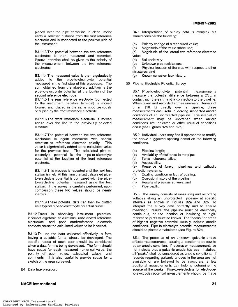
TM0497-2002
placed over the pipe centerline in clean, moist earth a selected distance from the first reference electrode and is connected to the positive side of the instrument.
B3.11.3 The potential between the two reference electrodes is then measured and recorded. Special attention shall be given to the polarity of the measurement between the two reference electrodes.
B3.11.4 The measured value is then algebraically added to the pipe-to-electrolyte potential measured in the first step of this procedure. The sum obtained from the algebraic addition is the pipe-to-electrolyte potential at the location of the second reference electrode. B3.11.5 The rear reference electrode (connected to the instrument negative terminal) is moved forward and placed in the same spot previously occupied by the front reference electrode.
B3.11.6 The front reference electrode is moved ahead over the line to the previously selected d istance.
B3.11.7 The potential between the two reference electrodes is again measured with special attention to reference electrode polarity. This value is algebraically added to the calculated value for the previous test. This calculated pipe-to- electrolyte potential is the pipe-to-electrolyte potential at the location of the front reference electrode.
B3.11.8 This process is repeated until the next test station is met. At this time the last calculated pipe- to-electrolyte potential is compared with the pipe- to-electrolyte potential measured using the test station. If the survey is carefully petformed, upon comparison these two values should be nearly id en t ica I.
B3.11.9 These potential data can then be plotted as a typical pipe-to-electrolyte potential curve.
B3.12 Errors in observing instrument polarities, incorrect algebraic calculations, unbalanced reference electrodes, and poor earthkeference electrode contacts cause the calculated values to be incorrect.
B3.13 To use the data collected effectively, a form having a suitable format should be developed. The specific needs of each user should be considered when a data form is being developed. The form should have space for each measured numerical value, the polarity of each value, calculated values, and comments. It is also useful to provide space for a sketch of the area surveyed.
B4 Data Interpretation:
B4.1 Interpretation of survey data is complex but should consider the following:
(a) (b) (c) value; (d) Soil resistivity; (e) Unknown pipe resistances; (f) structures; and (9) Known corrosion leak history.
B5 Pipe-to-Electrolyte Potential Survey
Polarity change of a measured value; Magnitude of the value measured; Magnitude of the lateral two-reference-electrode
Physical location of the pipe with respect to other
B5.1 Pipe-to-electrolyte potential measurements measure the potential difference between a CSE in contact with the earth and a connection to the pipeline. When taken and recorded at measurement intervals of 3 m (IO ft) directly over a pipeline, these measurements are useful in locating suspected anodic conditions of an unprotected pipeline. The interval of measurement may be shortened when anodic conditions are indicated or other unusual conditions occur (see Figures B2a and B2b).
B5.2 Individual users may find it appropriate to modify the above suggested spacing based on the following conditions.
(a) Pipeline length; (b) (c) Terrain characteristics; (d) Accessibility; (e) Presence of foreign pipelines and cathodic protection systems; (f) (9) (h) (i) Pipe depth.
Availability of test leads to the pipe;
Coating condition or lack of coating; Corrosion history of the pipeline; Results of previous surveys; and
B5.3 The survey consists of measuring and recording voltages along an unprotected pipeline at specific intervals as shown in Figures B2a and B2b. To interpret the survey data correctly and to ensure meaningful results, the pipeline must be electrically continuous, or the location of insulating or high- resistance joints must be known. The “peaks,” or areas of highest negative potential, usually indicate anodic conditions. Pipe-to-electrolyte potential measurements should be plotted or tabulated (see Figure B2c).
B5.4 The presence of an unknown galvanic anode affects measurements, causing a location to appear to be an anodic condition. If records or measurements do not indicate that a galvanic anode has been installed, all “peaks” shall be considered as anodic conditions. If records regarding galvanic anodes in the area are not available or are believed to be inaccurate, a few additional measurements can help to determine the source of the peaks. Pipe-to-electrolyte (or electrode- to-electrode) potential measurements should be made
NACE International 21
COPYRIGHT NACE InternationalLicensed by Information Handling ServicesCOPYRIGHT NACE InternationalLicensed by Information Handling Services
TM0497-2002
in 0.3-m (14) increments for about 1.5 to 3.0 m (5 to 10 ft) laterally to the pipe and through the “peak.” The maximum potential will occur a few feet to the side of the pipe if the peak is due to a galvanic anode. Moreover, if the pipe location is known with certainty and a galvanic anode is present, the potentials will be a minimum over or to the side of the pipe opposite where the maximum occurs. The closer the transverse measurements are to the anode, the more the location of the minimum will be shifted away from the side of the pipe opposite the location of the maximum.
B5.5 Stray current flowing to a pipe from sources such as foreign rectifiers and electrified railroads cause the pipe at that location to have more-negative potential and may be misinterpreted as an anodic condition. Stray current discharging from a pipe can cause a less- negative potential and be misinterpreted as a cathodic condition.
B6 Cathodic Protection Using the Net Protective Current Technique
B6.1 Cathodic protection should be applied to the anodic area(s).
B6.2 It is necessary to wait until polarization has stabilized before making a detailed evaluation of the net current protective level. Polarization of bare pipe may require a relatively long time ranging up to several months.
B6.3 When an impressed current source is used, the side drain potential (potential gradient lateral to the pipe longitudinal direction) should be measured at the predetermined anodic condition with the protective current applied. Relative to the reading directly over the pipe, a higher (more-negative) reading with the reference electrode lateral to the pipe indicates that current is being conducted to the pipe at this point. The amount of current flow indicated by this method may not be enough to control small local corrosion cells.
B6.4 Galvanic anodes are usually installed at or near the location of the anodic areas. Caution shall be used when interpreting the results of pipe-to-electrolyte potential measurements made close to an anode.
B6.5 Monitoring of cathodic protection can be simplified by establishing test points and recording the pipe-to-electrolyte potential exhibited when the side drain measurements indicate a net current flow to the pipe. These potentials may then be used to monitor the level of cathodic protection.
22 NACE International
COPYRIGHT NACE InternationalLicensed by Information Handling ServicesCOPYRIGHT NACE InternationalLicensed by Information Handling Services
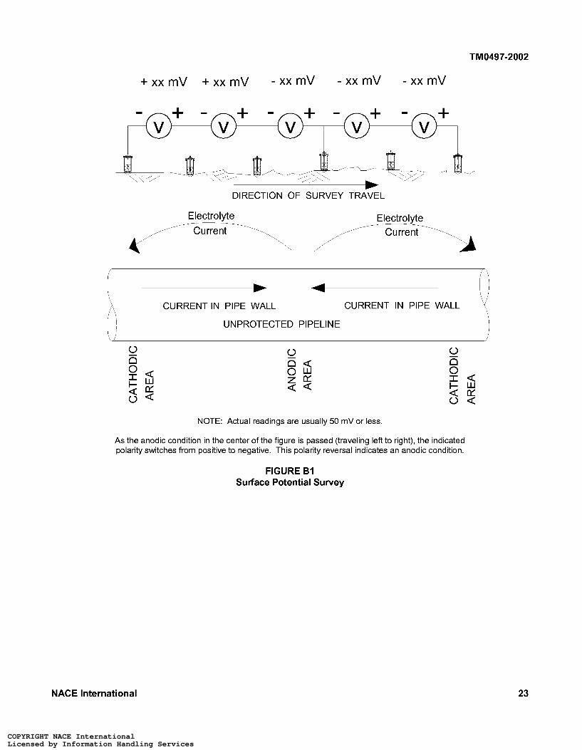
TM0497-2002
+ x x m V + x x m V - x x m V - x x m V - x x m V
DIRECTION OF SURVEY TRAVEL
Electrolvte Electrolvte Current J
f o . . CURRENTIN PIPE WALL CURRENT IN PIPE WALL
UNPROTECTED PIPELINE
o o w E a 2 %
NOTE: Actual readings are usually 50 mV or less.
As the anodic condition in the center of the figure is passed (traveling left to right), the indicated polarity switches from positive to negative. This polarity reversal indicates an anodic condition.
FIGURE B I Surface Potential Survey
NACE International 23
COPYRIGHT NACE InternationalLicensed by Information Handling ServicesCOPYRIGHT NACE InternationalLicensed by Information Handling Services
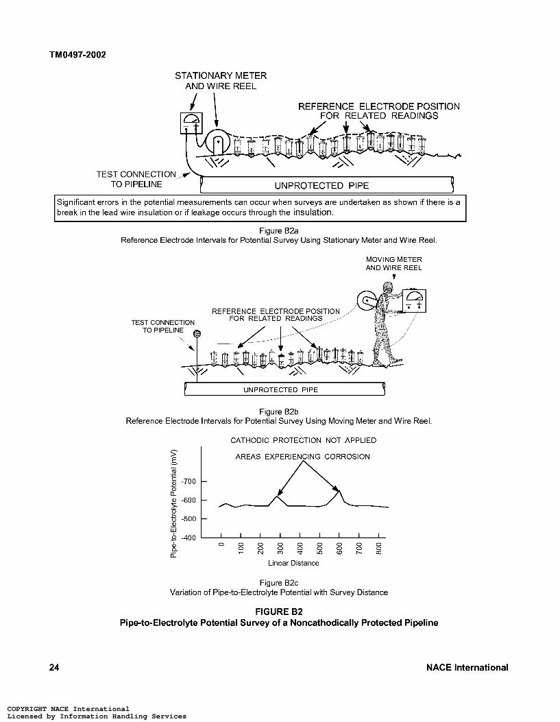
TM0497-2002
STATIONARY METER AND WIRE REEL
REFERENCE ELECTRODE POSITION ED READINGS
TEST CONNECTION TO PIPELINE UN PROTECTED PI PE 9
Significant errors in the potential measurements can occur when surveys are undertaken as shown if there is a break in the lead wire insulation or if leakage occurs through the insulation.
Figure B2a Reference Electrode Intervals for Potential Survey Using Stationary Meter and Wire Reel.
MOVING METER AND WIRE REEL
t
REFERENCE ELECTRODE POSIT1 FOR RELATED READ1 TEST CONNE
TO PIPELI
P UN PROTECTED PI PE Y Figure B2b
Reference Electrode Intervals for Potential Survey Using Moving Meter and Wire Reel.
CATHODIC PROTECTION NOT APPLIED - I AREAS EXPERIENCING CORROSION >
E
n
-5. -600
0 0 0 0 0 0 0 0 0 0 0 0 0 0 0 0 0 r N m b i n w b o O
8 a Q
Linear Distance
Figure B2c Variation of Pipe-to-Electrolyte Potential with Survey Distance
FIGURE B2 Pipe-to-Electrolyte Potential Survey of a Noncathodically Protected Pipeline
24 NACE International
COPYRIGHT NACE InternationalLicensed by Information Handling ServicesCOPYRIGHT NACE InternationalLicensed by Information Handling Services
TM0497-2002
. . . . . . . . . . . . . . . . . . . . . . . . . . . . . . . . . . . . . . . . . . . . . . . . . . . . . . . . . . . . . . . . . . . . . . . .
Appendix C: Using Coupons to Determine Adequacy of Cathodic Protection
C I Coupons have been used judiciously, particularly when accompanied by other engineering tools and data, to evaluate whether cathodic protection at a test site complies with a given criterion. See NACE Publication 352014 for more information on coupon use. The following test procedures are suggested as guides.
C2 Cathodic Protection Coupon Test Method I-for Negative 850 mV Polarized Pipe-to-Electrolyte Potential of Steel and Cast Iron Piping
C2.1 Scope
This method uses a cathodic protection coupon to assess the adequacy of cathodic protection on a steel or cast iron pipeline according to the criterion stated in NACE Standard RP0169,’ Paragraph 6.2.2.1.2:
A negative polarized potential of at least 850 mV relative to a saturated coppedcopper sulfate reference electrode (CSE).
C2.2 General
C2.2.1 This method uses a coupon to assess the adequacy of cathodic protection applied to a selected test site. A cathodic protection coupon is a metal sample representing the pipeline at the test site and used for cathodic protection testing. The coupon should be:
(a) Nominally of the same metal and surface condition as the pipe; (b) Small to avoid excessive current drain on the cathodic protection system; (c) Placed at pipe depth in the same backfill as the pipe; (d) Prepared with all mill scale and foreign materials removed from the surface; and (e) Placed at a known location of an ineffective coating when the line is coated.
C2.2.2 A coupon has an insulated test lead brought above ground and, during normal operations, connected to a pipeline test lead. The coupon receives cathodic protection current and represents the pipeline at the test site. For testing purposes, this connection is opened, and the polarized potential of the coupon is measured. The time the connection is open to measure the coupon’s “ow’ potential should be minimized to avoid significant depolarization of the coupon. The “ow’ period is typically less than 3 seconds. When possible, coupon current direction and magnitude should be verified, using a current clip gauge or resistor permanently placed in series with the coupon lead. Measurements showing discharge
of current from the coupon should be reason to question the validity of using a coupon at the test site.
C2.2.3 The significance of voltage drops due to currents from other sources may not be a problem when a coupon is used to represent the pipeline. The coupon’s small size may reduce the effect of these voltage drops. The magnitude of these voltage drops can be quantified by interrupting cathodic protection current sources while the coupon is disconnected and noting whether there is a shift in the coupon-to-electrolyte potential.
C2.3 Comparison with Other Methods
C2.3.1 Advantages
(a) Can provide a polarized coupon-to- electrolyte potential, free of voltage drop, with a minimum of specialized equipment, personnel, and vehicles; and (b) Can provide a more comprehensive evaluation of the polarization at the test site than conventional pipe-to-electrolyte potential measurements that may be influenced by the location, size, and number of coating holidays when the pipeline is coated.
C2.3.2 Disadvantage-Can have high initial costs to install coupons, especially for existing pipelines.
C2.4 Basic Test Equipment
C2.4.1 Voltmeter with adequate input impedance. Commonly used digital instruments have a nominal impedance of 10 megaohms. An analog instrument with an internal resistance of 100,000 ohms per volt may be adequate in certain circumstances in which the circuit resistance is low. A potentiometer circuit may be necessary in other instances.
C2.4.2 Two color-coded meter leads with clips for connection to the coupon and reference electrode.
C2.4.3 Reference electrode
C2.4.3.1 CSE
C2.4.3.2 Other standard reference electrodes may be substituted for the CSE. These reference electrodes are described in Appendix A, Paragraph A2.
C2.5 Procedure
NACE International 25
COPYRIGHT NACE InternationalLicensed by Information Handling ServicesCOPYRIGHT NACE InternationalLicensed by Information Handling Services
TM0497-2002
C2.5.1 Before the test, verify that:
(a) Cathodic protection equipment has been installed and is operating properly; and (b) Coupon is in place and connected to a pipe I i ne test lead.
Time should be allowed for the pipeline and coupon potentials to reach polarized values.
C2.5.2 Determine the location of the site to be tested. Selection of a site may be based on:
(a) (b) Other protection systems, structures, and anodes that may influence the pipe-to-electrolyte and coupon-to-electrolyte potentials; (c) Electrical midpoints between protection devices; (d) Known location of an ineffective coating when the line is coated; and (e) Location of a known or suspected corrosive environment.
Location accessible for future monitoring;
C2.5.3 Make electrical contact between the reference electrode and the electrolyte at the test site as close to the coupon as is practicable.
C2.5.4 Connect the voltmeter to the coupon test lead and reference electrode as described in Paragraph 5.6.
C2.5.5 Measure and record the pipeline and coupon “on” potentials.
C2.5.6 Momentarily disconnect the coupon test lead from the pipeline test lead and immediately measure and record the coupon-to-electrolyte “ow’ potential and its polarity with respect to the reference electrode. This should be petformed quickly to avoid depolarization of the coupon.
C2.5.7 Reconnect the coupon test lead to the pipeline test lead for normal operations.
C2.6 Evaluation of Data
Cathodic protection may be judged adequate at the test site if the polarized coupon-to-electrolyte potential is negative 850 mV, or more negative, with respect to a CSE. The polarized potential of the coupon depends on the coupon sutface condition, the soil in which the coupon is placed, its level of polarization, and its time polarized. Therefore, the polarized potential of the coupon may not be the same as that of the pipe and may not accurately reflect the polarization on the pipe at the coupon location. It must also be understood that the polarization measured on the pipeline is a “resultant” of the variations of polarization on the pipe at the test site. The causes of these variations include the pipe sutface condition, soil strata variations, oxygen differentials, and length of time the pipe has been
polarized. possible.
Making precise comparisons may not be
C2.7 Monitoring
When the polarized coupon-to-electrolyte potential has been determined to equal or to exceed a negative 850 mV, the pipeline “on” potential may be used for monitoring unless significant environmental, structural, coating integrity, or cathodic protection system para meters have changed.
C3 Cathodic Protection Coupon Test Method 2-for 100 mV Cathodic Polarization of Steel, Cast Iron, Aluminum, and Copper Piping
C3.1 Scope
This method uses cathodic protection coupon polarization decay to assess the adequacy of cathodic protection on a steel, cast iron, aluminum, or copper pipeline according to the criteria stated in NACE Standard RPOI 69,’ Paragraphs 6.2.2.1.3, 6.2.3.1, or 6.2.4.1 (depending on the pipe metal). The paragraph below states Paragraph 6.2.2.1.3:
The following criterion shall apply: A minimum of 1 O0 mV of cathodic polarization between the structure sutface and a stable reference electrode contacting the electrolyte. The formation or decay of polarization can be measured to satisfy this criterion.
C3.2 General
Ferrous, aluminum, and copper pipelines may be adequately cathodically protected when applying cathodic protection causes a polarization change of 1 O0 mV or more with respect to a reference potential.
C3.2.1 This method uses a coupon to assess the adequacy of cathodic protection applied at a test site. A cathodic protection coupon is a metal sample representing the pipeline at the test site and used for cathodic protection testing. The coupon should be:
(a) Nominally of the same metal and surface condition as the pipe; (b) Small to avoid excessive current drain on the cathodic protection system; (c) Placed at pipe depth in the same backfill as the pipe; (d) Prepared with all mill scale and foreign materials removed from the surface; and (e) Placed at a known location of an ineffective coating when the line is coated.
C3.2.2 The significance of voltage drops due to currents from other sources may be accounted for when a coupon is used to represent the pipeline. The magnitude of these voltage drops can be
26 NACE International
COPYRIGHT NACE InternationalLicensed by Information Handling ServicesCOPYRIGHT NACE InternationalLicensed by Information Handling Services
TM0497-2002
quantified by interrupting cathodic protection sources while the coupon is disconnected and noting whether there is a shift in the coupon-to- electrolyte potential.
C3.2.3 A coupon has an insulated test lead brought above ground and, during normal operations, connected to a pipeline test lead. The coupon receives cathodic protection current and represents the pipeline at the test site. For testing purposes, this connection is opened, and the polarized ?ow? potential of the coupon is measured. The time the connection is open to measure the coupon?s ?ow? potential should be minimized to avoid significant depolarization of the coupon. The ?ow? period is typically less than 3 seconds. The coupon is then allowed to depolarize. When possible, coupon current direction and magnitude should be verified, using a current clip gauge or resistor permanently placed in series with the coupon lead. Measurements showing discharge of current from the coupon should be reason to question the validity of using a coupon at the test site.
C3.3 Comparison with Other Methods
C3.3.1 Advantages
(a) Can measure coupon-to-electrolyte polari- zation decay with a minimum of specialized equipment, personnel, and vehicles; (b) Can provide an indication of the amount of polarization present at the test site without interrupting the cathodic protection current supplied to the pipeline; (c) Can provide a better indication of cathodic protection levels due to eliminating the effects of ?long-line? current flow when the pipeline ?ow? potentials are measured.
C3.3.2 Disadvantage-Can have high initial costs to install a coupon, especially for existing pipelines.
C3.4 Basic Test Equipment
C3.4.1 Voltmeter with adequate input impedance. Commonly used digital instruments have a nominal impedance of 10 megaohms. An analog instrument with an internal resistance of 100,000 ohms per volt may be adequate in certain circumstances where the circuit resistance is low. A potentiometer circuit may be necessary in other instances.
C3.4.2 Two color-coded meter leads with clips for connection to the coupon and reference electrode.
C3.4.3 Reference electrode
C3.4.3.2 Other standard reference electrodes may be substituted for the CSE. These reference electrodes are described in Appendix A, Paragraph A2.
C3.5 Procedure
C3.5.1 Before the test, verify that:
(a) (b) and operating properly; and (c) Coupon is in place and connected to a pipeline test lead.
Cathodic protection equipment is installed
Time shall be allowed for the pipeline and coupon potentials to reach polarized values.
C3.5.2 Determine the location of the site to be tested. Selection of a site may be based on:
(a) (b) Other protection systems, structures, and anodes that may influence the pipe-to-electrolyte and coupon-to-electrolyte potentials; (c) Electrical midpoints between protection devices; (d) Known location of an ineffective coating when the line is coated; and (e) Location of a known or suspected corrosive environment.
Location accessible for future monitoring;
C3.5.3 Make electrical contact between the reference electrode and the electrolyte at the test site as close to the coupon as is practicable.
C3.5.3.1 Identify the location of the electrode to allow it to be returned to the same location for subsequent tests.
C3.5.4 Connect the voltmeter to the coupon test lead and reference electrode as described in Paragraph 5.6.
C3.5.5 Measure and record the pipeline and coupon ?on? potentials.
C3.5.6 Disconnect the coupon test lead from the pipeline test lead and immediately measure the coupon-to-electrolyte potential.
C3.5.6.1 The coupon-to-electrolyte potential becomes the ?base line value? from which polarization decay is measured.
C3.5.7 Record the coupon-to-electrolyte ?ow? potential and its polarity with respect to the reference e led rode.
C3.5.8 Leave the coupon test lead disconnected to allow the coupon to depolarize.
C3.4.3.1 CSE.
NACE International 27
COPYRIGHT NACE InternationalLicensed by Information Handling ServicesCOPYRIGHT NACE InternationalLicensed by Information Handling Services
TM0497-2002
C3.5.9 Measure and record the coupon-to- electrolyte potential periodically. The difference between it and the “ow’ potential is the amount of polarization decay. Continue to measure and record the coupon-to-electrolyte potential until it either:
(a) Has become at least 100 mV less negative than the “ow’ potential; or (b) Has reached a stable depolarized level.
C3.5.10 Reconnect the coupon test lead to the pipeline test lead for normal operations.
C3.6 Evaluation of Data
Cathodic protection may be judged adequate at the test site when 100 mV or more of polarization decay is measured with respect to a standard reference
electrode. The depolarized potential of the coupon depends on the coupon sutface condition, the soil in which the coupon is placed, its level of polarization, and its time polarized. Therefore, the depolarized potential of the coupon may not be the same as that of the pipe and may not accurately reflect the polarization on the pipe at the coupon location. It must also be understood that the polarization measured on the pipeline is a “resultant” of the variations of polarization on the pipe at the test site. These variations are caused by the pipe sutface condition, soil strata variations, oxygen differentials, and time the pipe has been polarized. Making precise comparisons may not be possible.
C3.7 Monitoring
When at least 100 mV or more of polarization decay has been measured, the pipeline “on” potential at the test site may be used for monitoring unless significant environmental, structural, coating integrity, or cathodic protection system parameters have changed.
28 NACE International
COPYRIGHT NACE InternationalLicensed by Information Handling ServicesCOPYRIGHT NACE InternationalLicensed by Information Handling Services


![Untersuchungen zur Beständigkeit hochfester HFI ...€¦ · -Standard NACE TM0177 12] -Standard NACE TM 0177 12] N H2SO 4 + 10 mg/l As 2O3 als Promotor, kathod der Güte hliffbilder](https://img.pdfslide.net/doc/110x75/5b16021b7f8b9a5e798c4099/untersuchungen-zur-bestaendigkeit-hochfester-hfi-standard-nace-tm0177-12.jpg)