Embed Size (px)
Citation preview
nailed it!introducing the design guide
for nail-laminated timber
chicagolandworkshops
tanyaluthi, p.e.fast +epp
march 7-8,2018
Disclaimer: This presentation was developed by a third party and is not
funded by WoodWorks or the Softwood Lumber Board
Copyright Materials
This presentation is protected by US and International Copyright laws.
Reproduction, distribution, display and use of the presentation without
written permission of the speaker is prohibited.
© Fast + Epp 2018

“The Wood Products Council” is
a Registered Provider with The
American Institute of Architects
Continuing Education Systems
(AIA/CES), Provider #G516.
Credit(s) earned on completion
of this course will be reported
to AIA CES for AIA members.
Certificates of Completion for
both AIA members and non-AIA
members are available upon
request.
This course is registered with
AIA CES for continuing
professional education. As
such, it does not include
content that may be deemed or
construed to be an approval or
endorsement by the AIA of any
material of construction or any
method or manner of handling,
using, distributing, or dealing in
any material or product.___________________________
Questions related to specific
materials, methods, and services will
be addressed at the conclusion of this
presentation.
AIA-registeredprovider

workshopdescription
Growing interest in mass timber has led to increased use not only of
cross-laminated timber, but nail-laminated timber (NLT or nail-lam) — a
lesser known but ostensibly more common material option. NLT is
created by fastening pieces of dimension lumber, stacked on edge, into
one structural element with nails or screws. It offers a unique aesthetic,
flexibility of form, fast erection and a light carbon footprint — and is a
cost-effective option for designers looking to expose wood structure.
Using lessons learned from real projects, this workshop will provide
practical strategies and guidance for the safe, predictable, and
economical use of NLT. Discussion will include architectural and
structural considerations, envelope and fabrication details, and key
information from the Nail-Laminated Timber Design and Construction
Guide, which was authored by the speakers.
learningobjectives
1. Review conceptual, planning and detailing considerations associated
with NLT, including MEP, acoustics, and form variation.
2. Discuss engineering procedures for gravity and lateral design,
including connection design, special loading conditions, and
calculating fire resistance.
3. Study the design of NLT assemblies as building enclosure elements,
while evaluating ways to mitigate heat, air and water flow into and out
of the building.
4. Consider how NLT is prefabricated and installed, along with best
practices for material procurement, tools and equipment, shipping,
storage, and lifting.

overview
odds &ends
gravitydesign
lateraldesign
connections
1
2
3
4
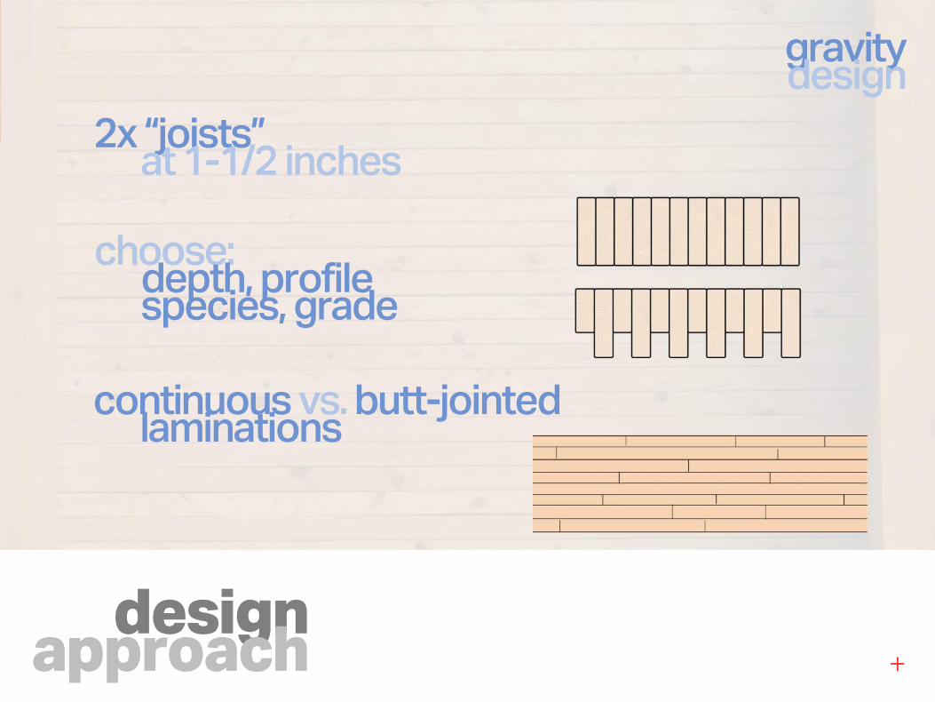
designapproach
gravitydesign
2x “joists”at 1-1/2 inches
choose:depth, profilespecies, grade
continuous vs. butt-jointedlaminations
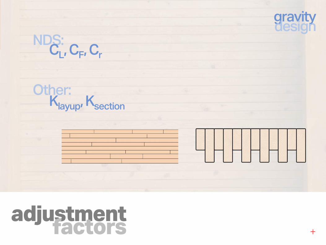
adjustmentfactors
NDS:CL, CF, Cr
gravitydesign
Other:Klayup, Ksection
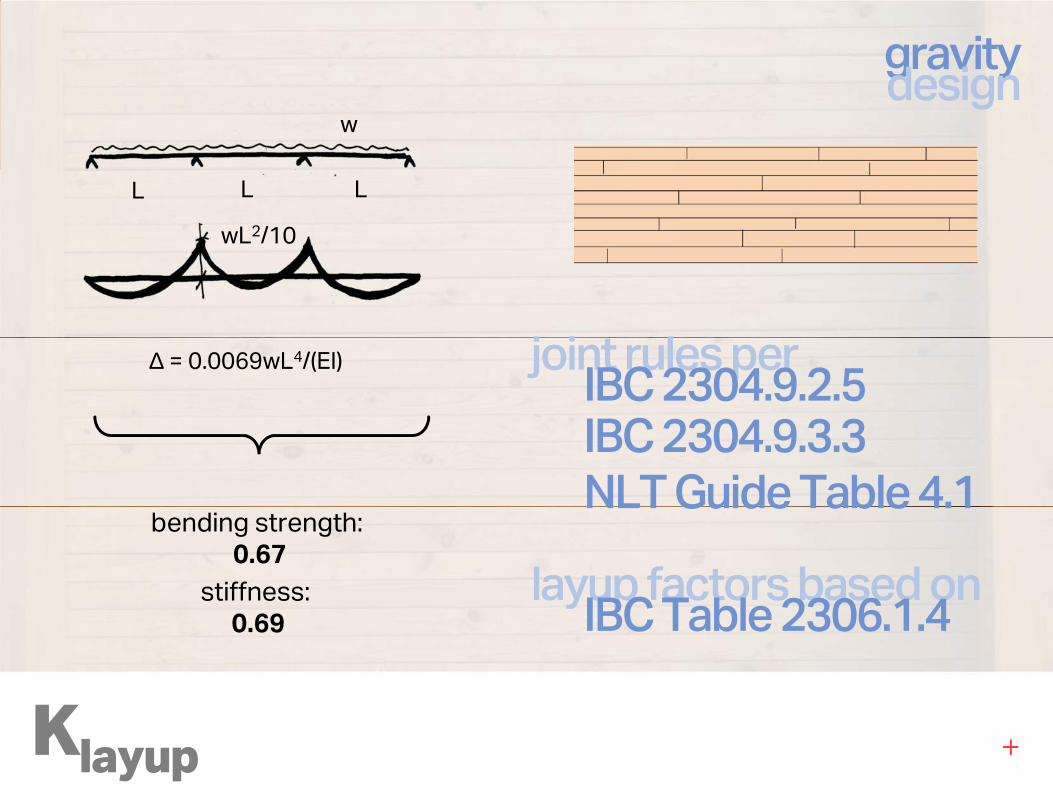
Klayup
gravitydesign
w
L L L
wL2/10
∆ = 0.0069wL4/(EI)
bending strength:
0.67
stiffness:
0.69
joint rules perIBC 2304.9.2.5IBC 2304.9.3.3
NLT Guide Table 4.1
layup factors based onIBC Table 2306.1.4
Klayup
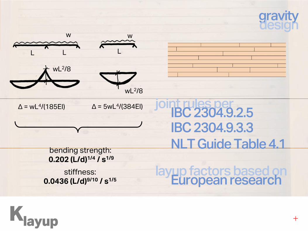
gravitydesign
w
LL L
w
wL2/8
wL2/8
∆ = 5wL4/(384EI)∆ = wL4/(185EI)
bending strength:
0.202 (L/d)1/4 / s1/9
stiffness:
0.0436 (L/d)9/10 / s1/5
joint rules perIBC 2304.9.2.5IBC 2304.9.3.3
NLT Guide Table 4.1
layup factors based onEuropean research
designexample
Klayup
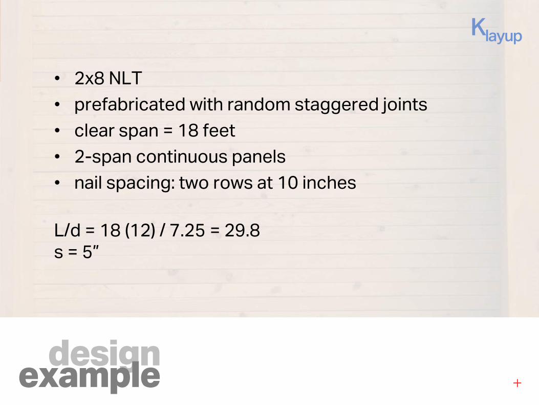
• 2x8 NLT
• prefabricated with random staggered joints
• clear span = 18 feet
• 2-span continuous panels
• nail spacing: two rows at 10 inches
L/d = 18 (12) / 7.25 = 29.8
s = 5”
designexample
Klayup
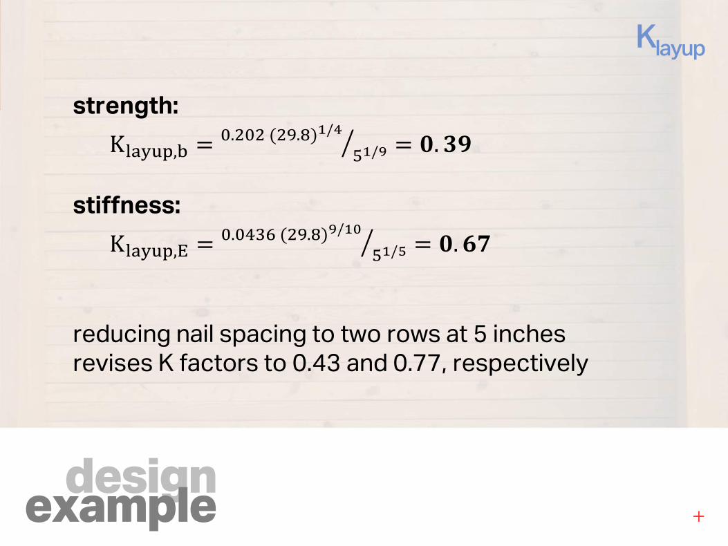
strength:
K�����,� .�����.���/���/�� �. ��
stiffness:
K�����,� .������.���/����/ � �. !"
reducing nail spacing to two rows at 5 inches
revises K factors to 0.43 and 0.77, respectively
Ksection
gravitydesign
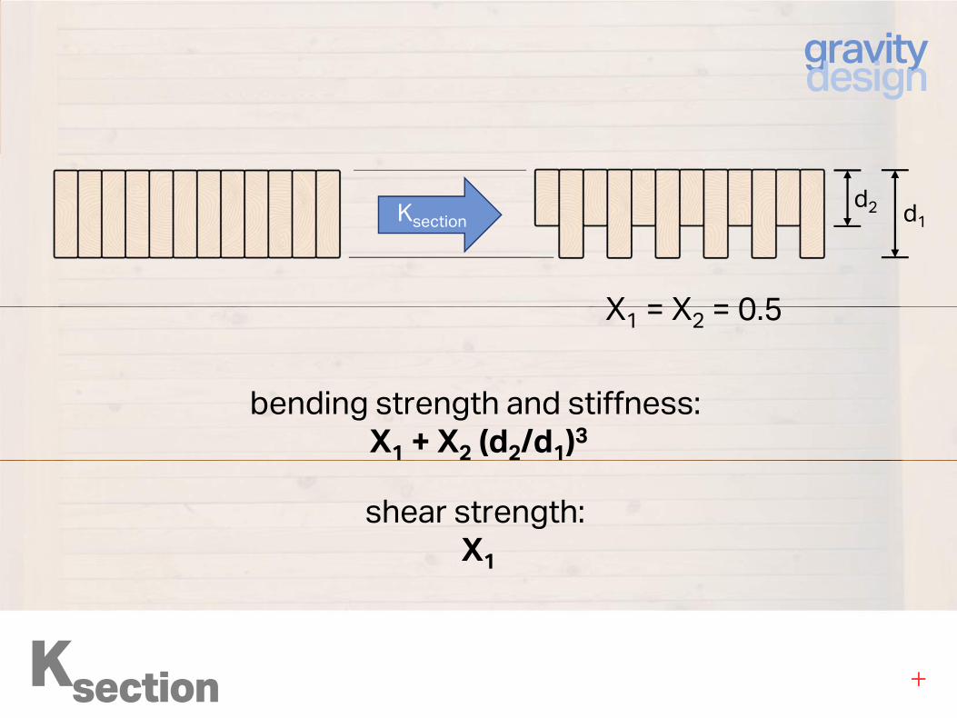
shear strength:
X1
bending strength and stiffness:
X1 + X2 (d2/d1)3
Ksection
X1 = X2 = 0.5
d1
d2
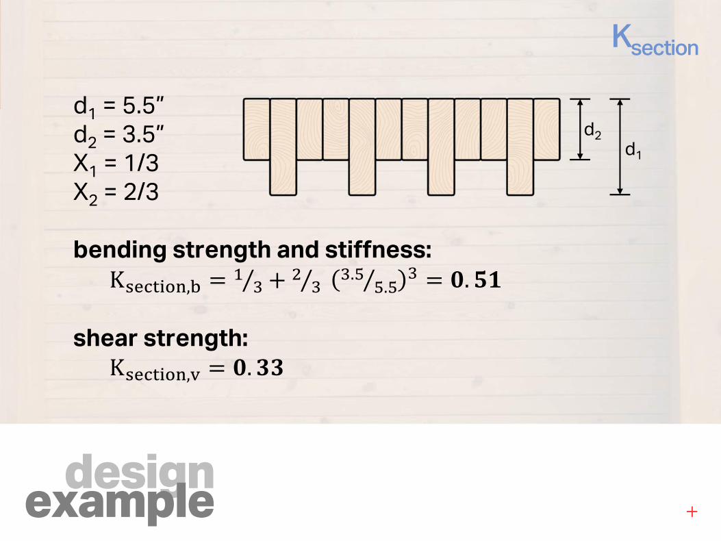
designexample
Ksection
d1 = 5.5”
d2 = 3.5”
X1 = 1/3
X2 = 2/3
bending strength and stiffness:
K#$%&'(),� * �⁄ , � �⁄ �.� �.�⁄ � �. -.
shear strength:
K#$%&'(),/ �. ��
d1
d2
bending& shear
NDS:Sections 3.2 – 3.5
(Bending Members)
Section 4.3 (Adjustment Factors)
Supplement Tables 4A, 4B, 4C, 4F (Reference Design Values)
gravitydesign
designexample
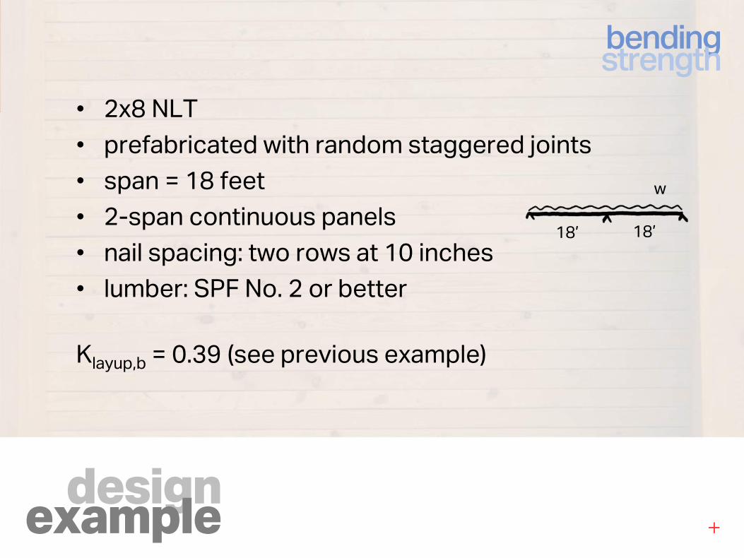
bendingstrength
• 2x8 NLT
• prefabricated with random staggered joints
• span = 18 feet
• 2-span continuous panels
• nail spacing: two rows at 10 inches
• lumber: SPF No. 2 or better
Klayup,b = 0.39 (see previous example)
18’ 18’
w
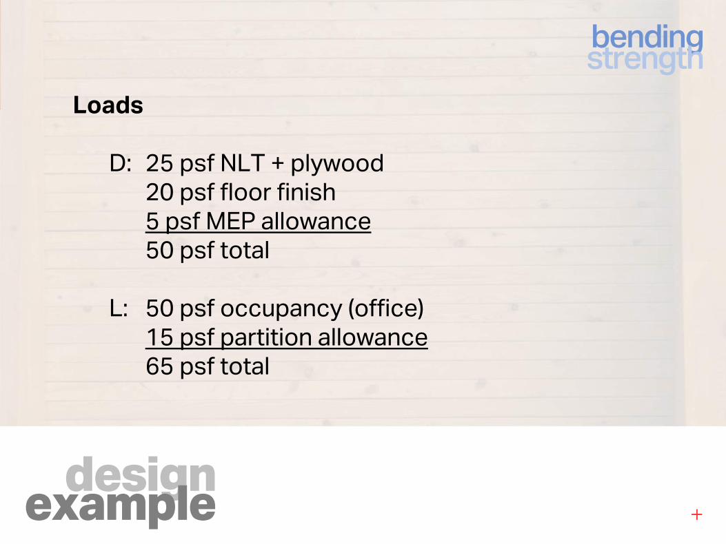
designexample
bendingstrength
Loads
D: 25 psf NLT + plywood
20 psf floor finish
5 psf MEP allowance
50 psf total
L: 50 psf occupancy (office)
15 psf partition allowance
65 psf total
designexample
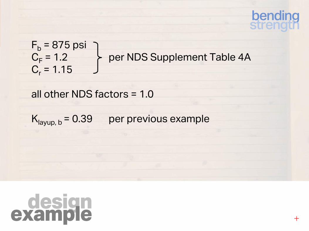
bendingstrength
Fb = 875 psi
CF = 1.2 per NDS Supplement Table 4A
Cr = 1.15
all other NDS factors = 1.0
Klayup, b = 0.39 per previous example
designexample
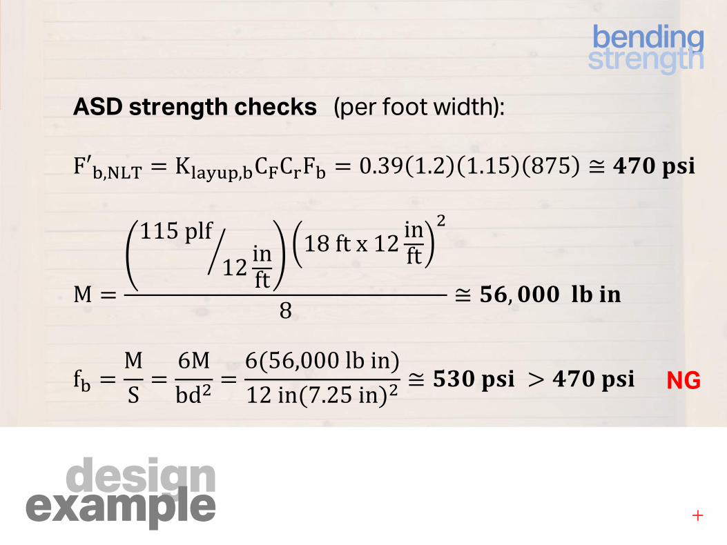
bendingstrength
ASD strength checks (per foot width):
F′�,234 K�����,�C6C7F� 0.39 1.2 1.15 875 ≅ A"�BCD
M
115plf12 inft
L 18ftx12 inft�
8 ≅ -!, ���NODP
f� MS 6M
bd� 6�56,000lbin�12in�7.25in�� ≅ -��BCD U A"�BCD NG
designexample
bendingstrength
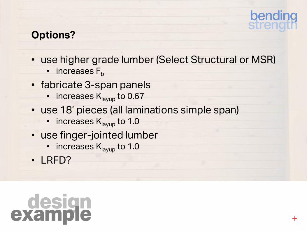
Options?
• use higher grade lumber (Select Structural or MSR)• increases Fb
• fabricate 3-span panels• increases Klayup to 0.67
• use 18’ pieces (all laminations simple span)• increases Klayup to 1.0
• use finger-jointed lumber• increases Klayup to 1.0
• LRFD?
designexample
bendingstrength
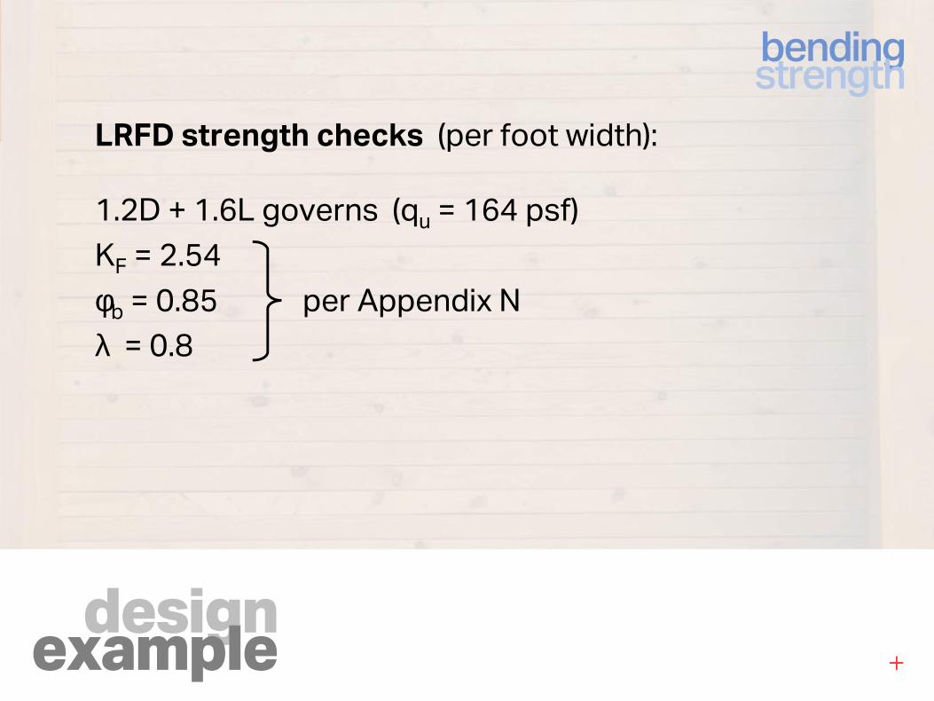
LRFD strength checks (per foot width):
1.2D + 1.6L governs (qu = 164 psf)
KF = 2.54
φb = 0.85 per Appendix N
λ = 0.8
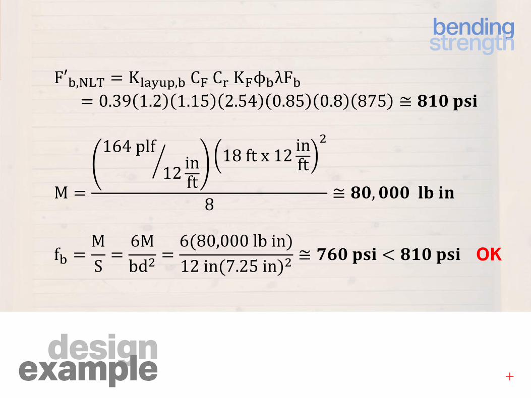
designexample
bendingstrength
F′�,234 K�����,�C6C7K6ϕ�λF� 0.39 1.2 1.15 2.54 0.85 0.8 875 ≅ Y.�BCD
M
164plf12 inft
L 18ftx12 inft�
8 ≅ Y�, ���NODP
f� MS 6M
bd� 6�80,000lbin�12in�7.25in�� ≅ "!�BCD Z Y.�BCD OK
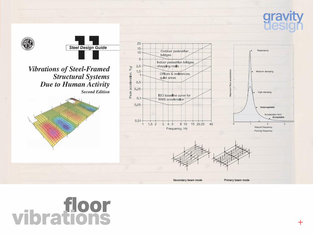
floorvibrations
gravitydesign
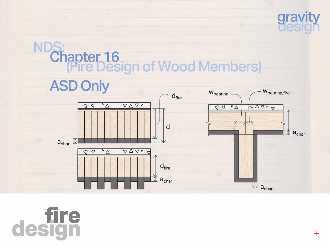
firedesign
gravitydesign
NDS:Chapter 16
(Fire Design of Wood Members)
ASD Only
achar
achar
achar
achar
dfire
dfire
d
wbearing,firewbearing
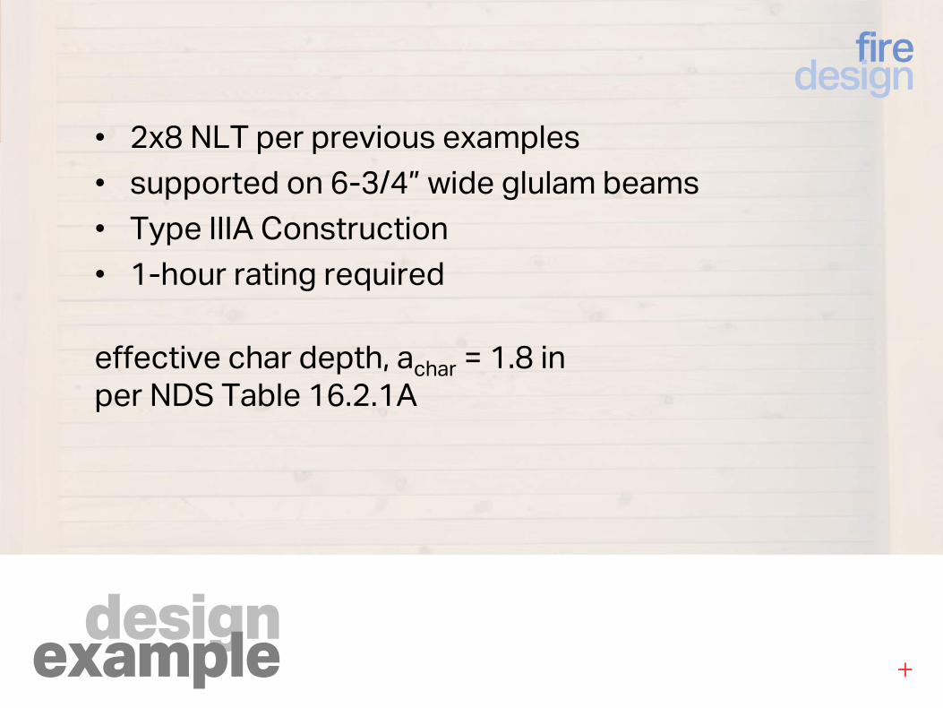
designexample
firedesign
• 2x8 NLT per previous examples
• supported on 6-3/4” wide glulam beams
• Type IIIA Construction
• 1-hour rating required
effective char depth, achar = 1.8 in
per NDS Table 16.2.1A
designexample
firedesign
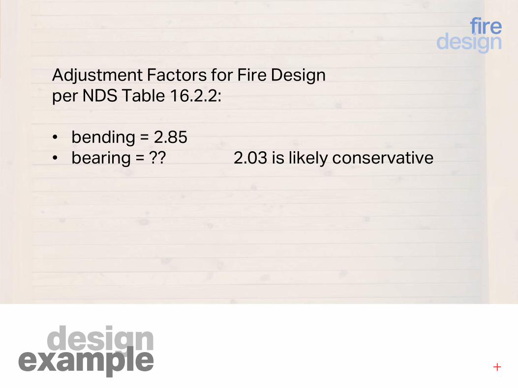
Adjustment Factors for Fire Design
per NDS Table 16.2.2:
• bending = 2.85
• bearing = ?? 2.03 is likely conservative
designexample
firedesign
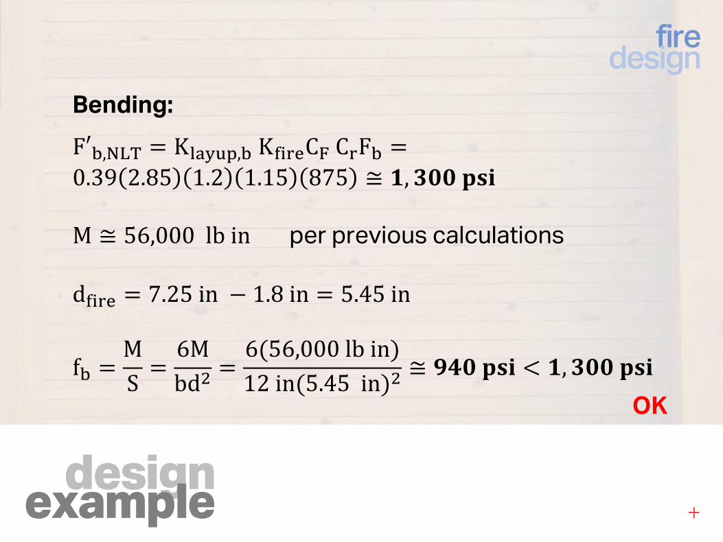
Bending:
F′�,234 K�����,�K['7$C6C7F� 0.39 2.85 1.2 1.15 875 ≅ ., ���BCD
M ≅ 56,000lbin per previous calculations
d['7$ 7.25in \ 1.8in 5.45in
f� MS 6M
bd� 6�56,000lbin�12in�5.45in�� ≅ �A�BCD Z ., ���BCD
OK
designexample
firedesign
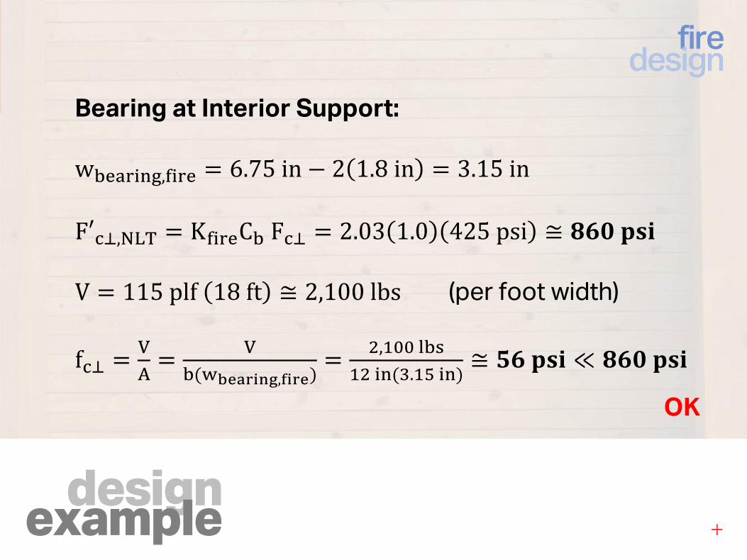
Bearing at Interior Support:
w�$�7')^,['7$ 6.75in \ 2 1.8in 3.15in
F′%_,234 K['7$C�F%_ 2.03 1.0 425psi ≅ Y!�BCD
V 115plf 18ft ≅ 2,100lbs (per foot width)
f%_ bc
b��defghijk,lihf�
�,*��#*�')��.*�')� ≅ -!BCD ≪ Y!�BCD
OK
overview
odds & ends
gravitydesign
lateraldesign
connections
1
2
3
4
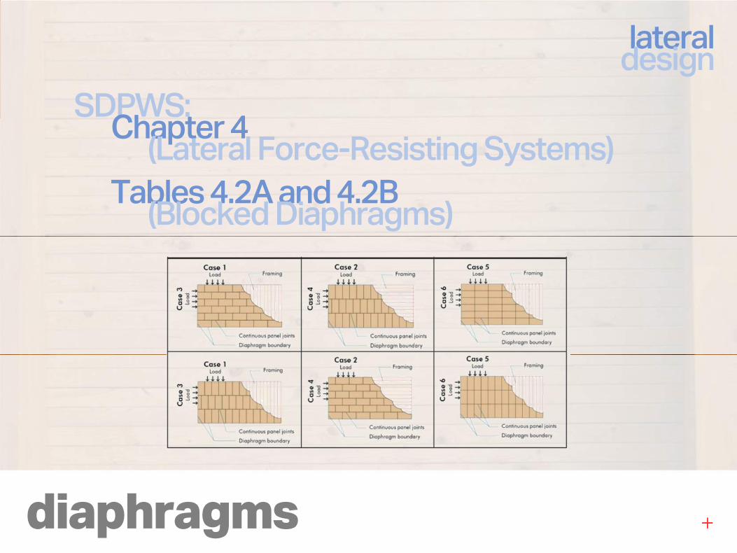
diaphragms
lateraldesign
SDPWS:Chapter 4
(Lateral Force-Resisting Systems)
Tables 4.2A and 4.2B(Blocked Diaphragms)
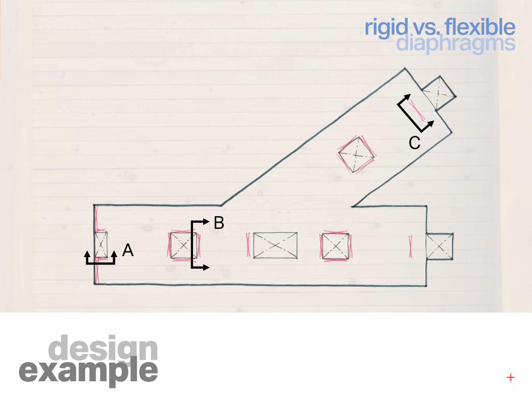
designexample
rigid vs. flexiblediaphragms
A
B
C
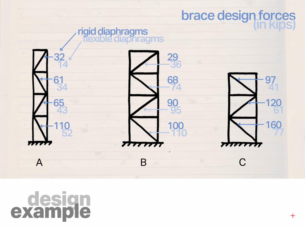
designexample
brace design forces(in kips)
3214
6134
6543
11052
A B C
rigid diaphragmsflexible diaphragms
2936
6874
9095
100110
9741
12061
16077
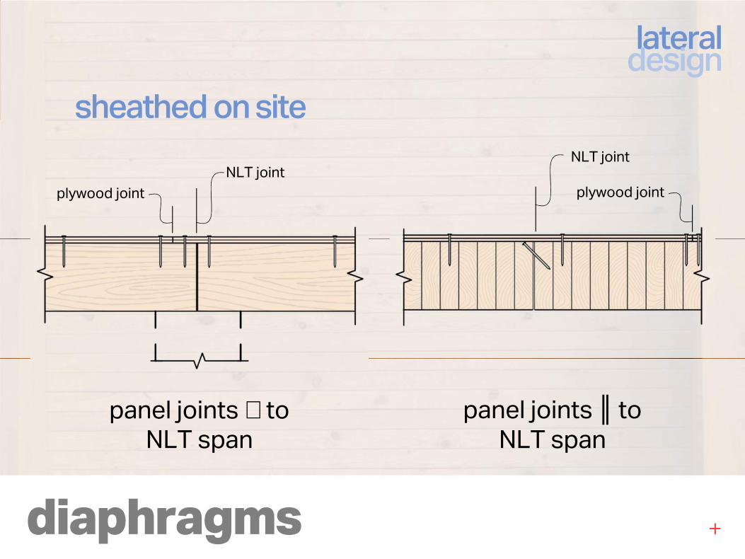
diaphragms
lateraldesign
sheathed on site
plywood jointNLT joint
NLT joint
plywood joint
panel joints ⊥ to NLT span
panel joints ║ to NLT span
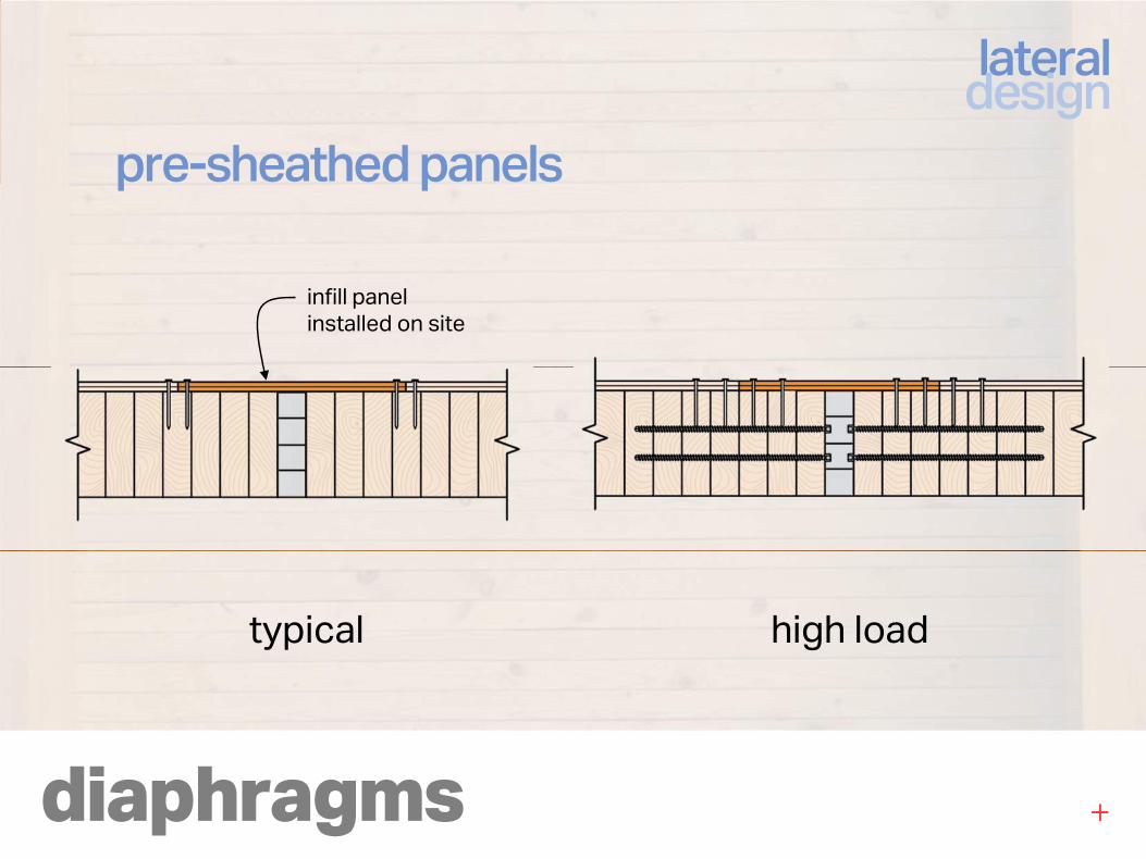
diaphragms
lateraldesign
pre-sheathed panels
typical high load
infill panel installed on site
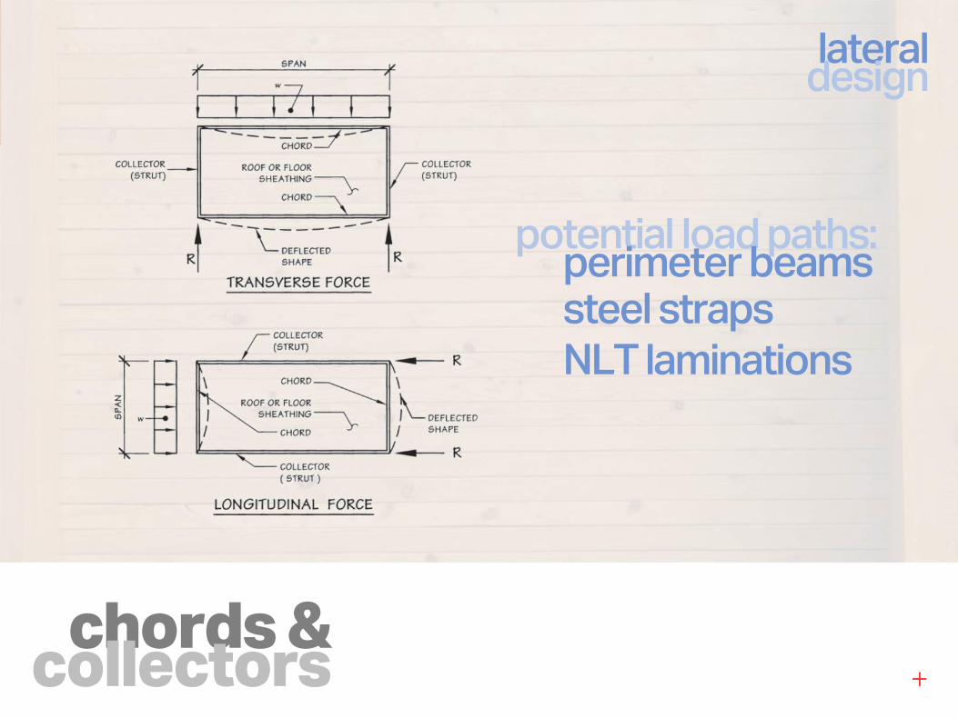
chords &collectors
lateraldesign
potential load paths:perimeter beamssteel straps
NLT laminations
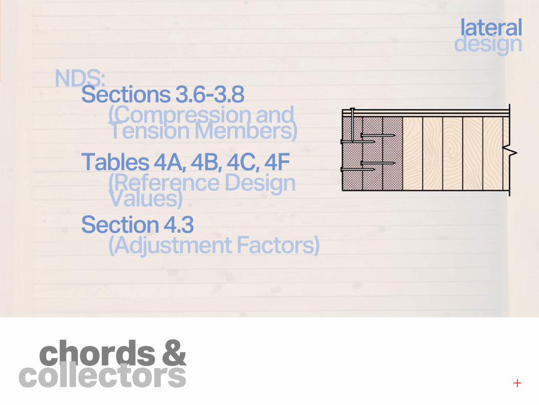
chords &collectors
lateraldesign
NDS:Sections 3.6-3.8
(Compression andTension Members)
Tables 4A, 4B, 4C, 4F (Reference Design Values)
Section 4.3 (Adjustment Factors)

overview
odds &ends
gravitydesign
lateraldesign
connections
1
2
3
4
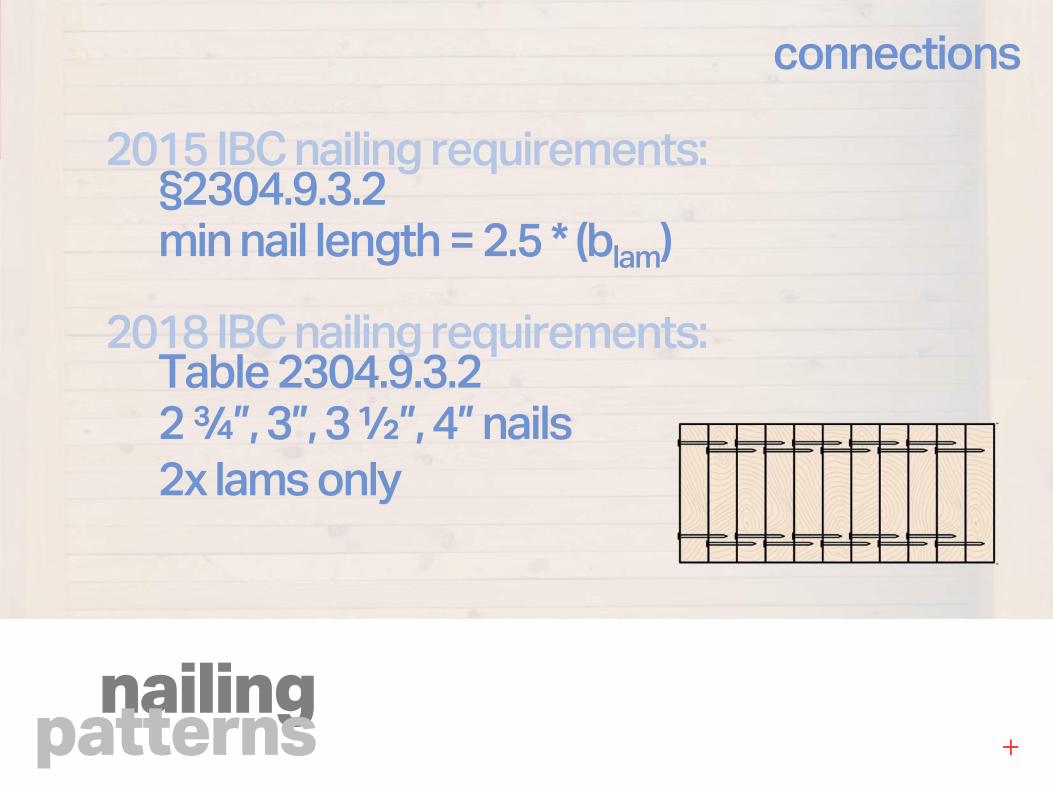
nailingpatterns
connections
2015 IBC nailing requirements:§2304.9.3.2 min nail length = 2.5 * (blam)
2018 IBC nailing requirements:Table 2304.9.3.22 ¾”, 3”, 3 ½”, 4” nails
2x lams only
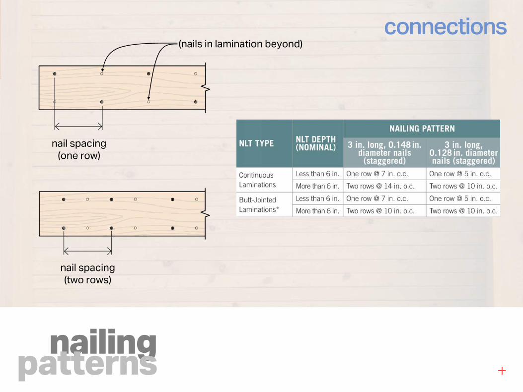
nailingpatterns
connections
nail spacing(two rows)
nail spacing(one row)
(nails in lamination beyond)
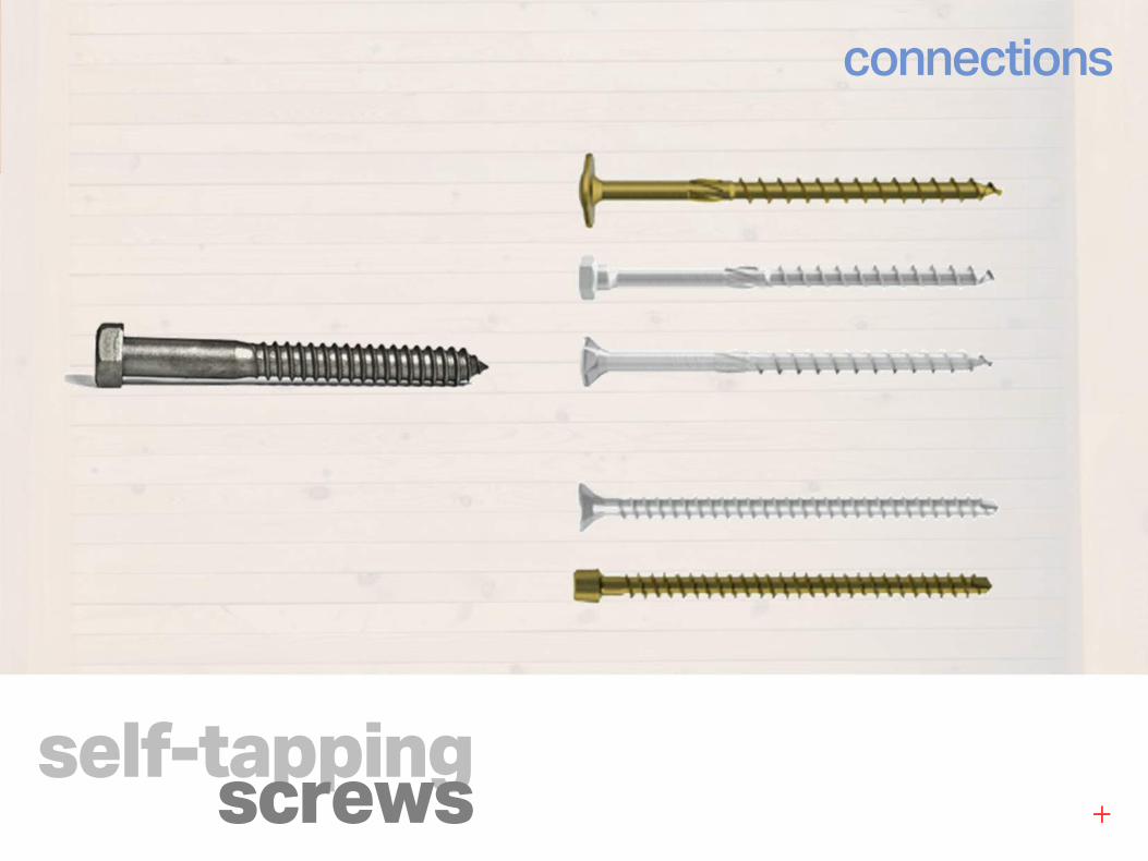
self-tappingscrews
connections
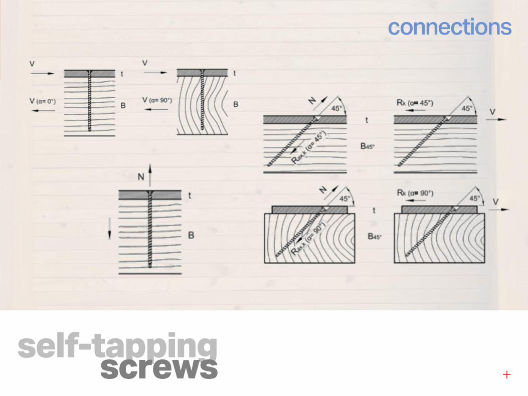
self-tappingscrews
connections
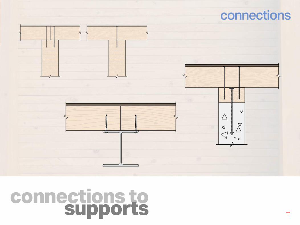
connections tosupports
connections
IBC toenailing requirements:§2304.9.3.2 feasible only for site-built NLT
alternative means and methods:match lateral and withdrawal strengthmatch lateral stiffness?
other rational approaches
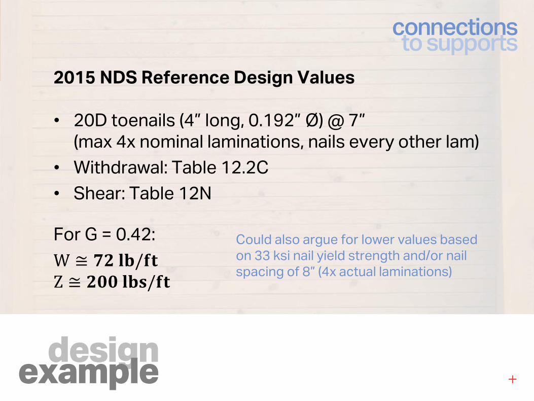
designexample
connectionsto supports
2015 NDS Reference Design Values
• 20D toenails (4” long, 0.192” Ø) @ 7”(max 4x nominal laminations, nails every other lam)
• Withdrawal: Table 12.2C
• Shear: Table 12N
For G = 0.42:
W ≅ "oNO/pqZ ≅ o��NOC/pq
Could also argue for lower values based on 33 ksi nail yield strength and/or nail spacing of 8” (4x actual laminations)
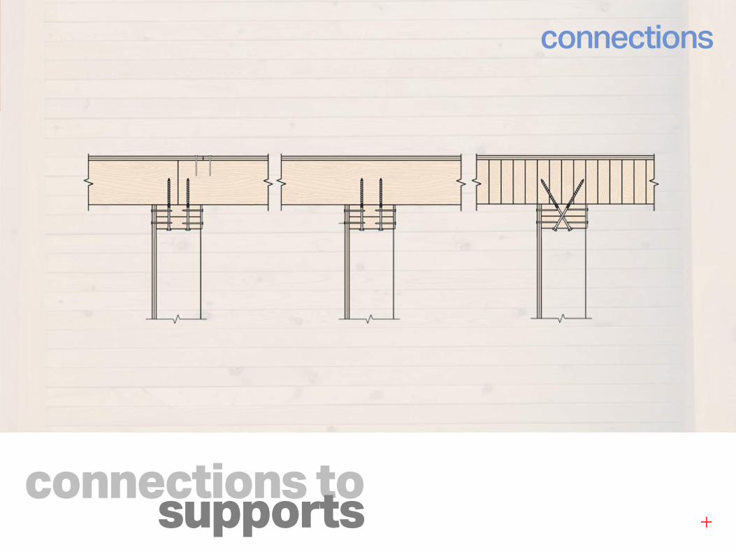
connections tosupports
connections
connections tosupports
connections
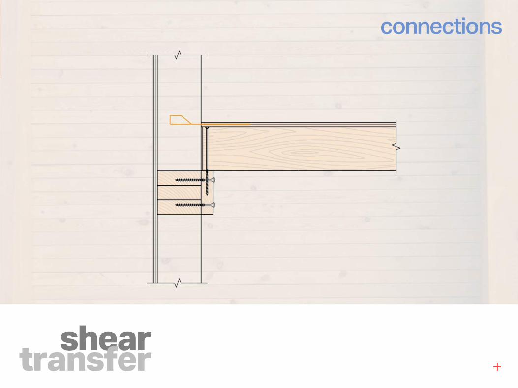
sheartransfer
connections

overview
odds &ends
gravitydesign
lateraldesign
connections
1
2
3
4
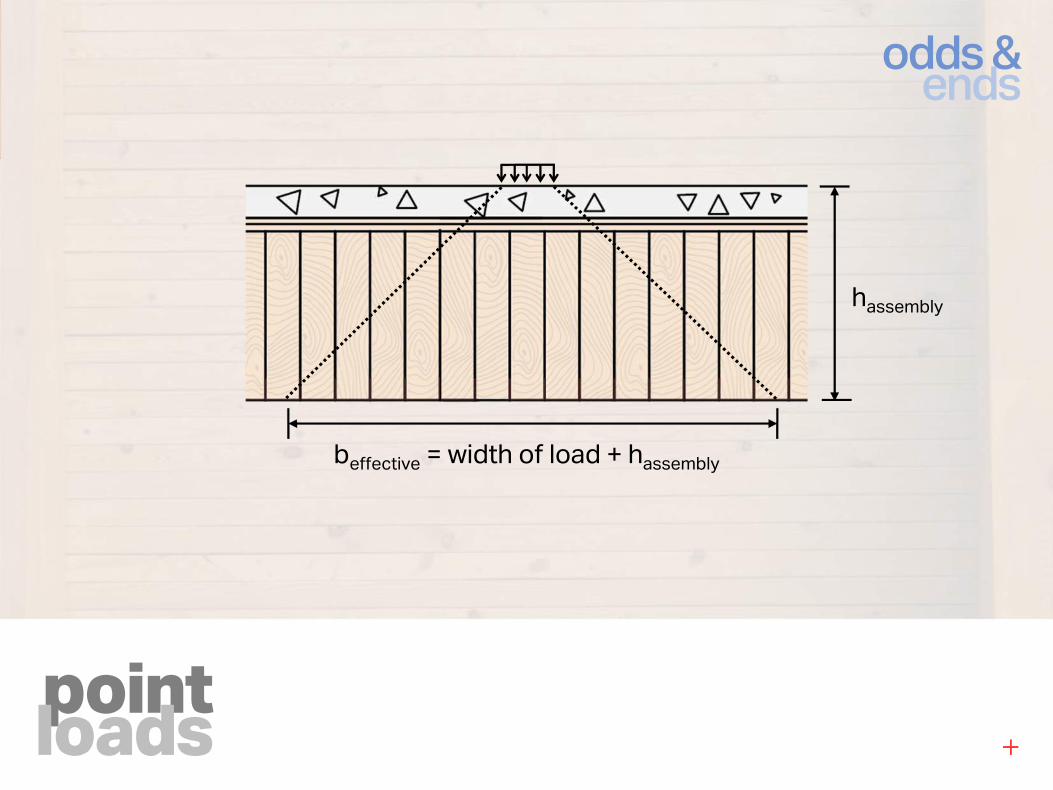
pointloads
odds &ends
hassembly
beffective = width of load + hassembly
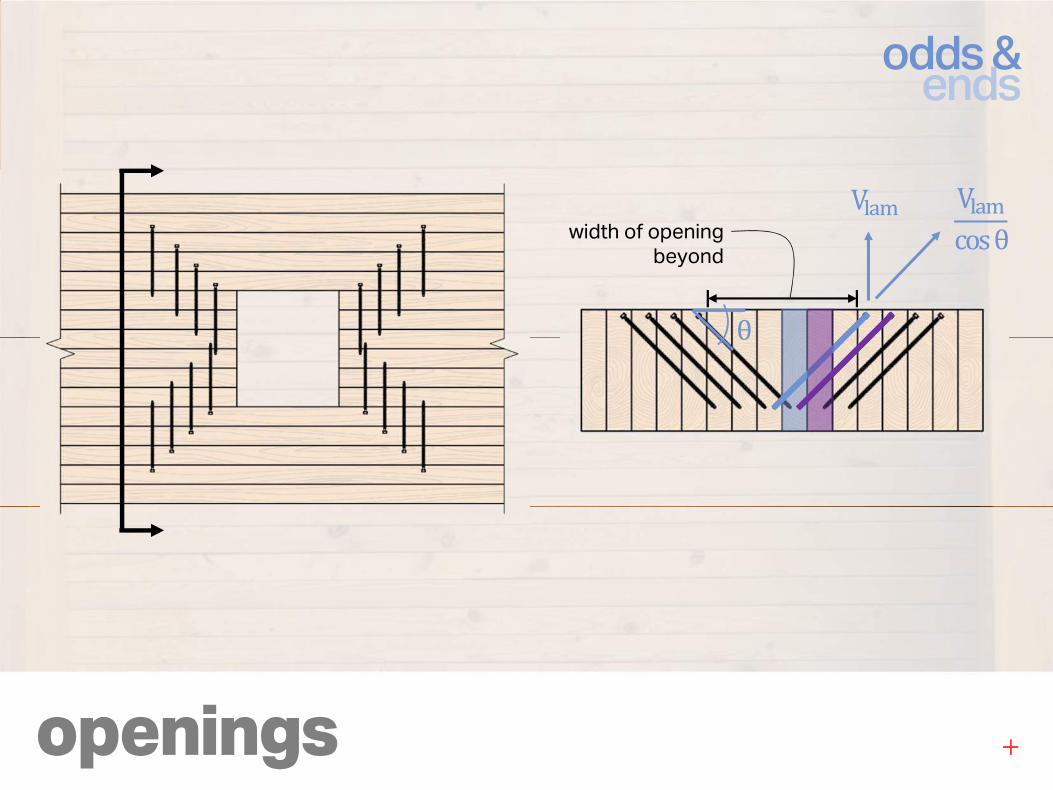
openings
odds &ends
V��scosθ
V��s
θ
width of opening beyond
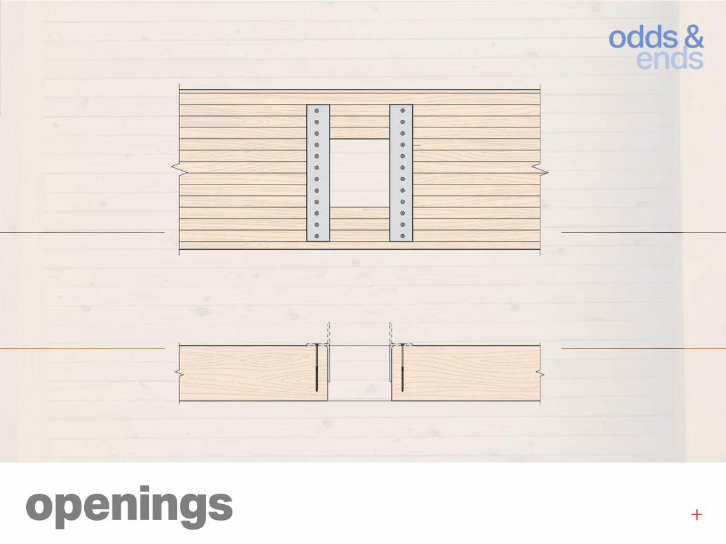
openings
odds &ends
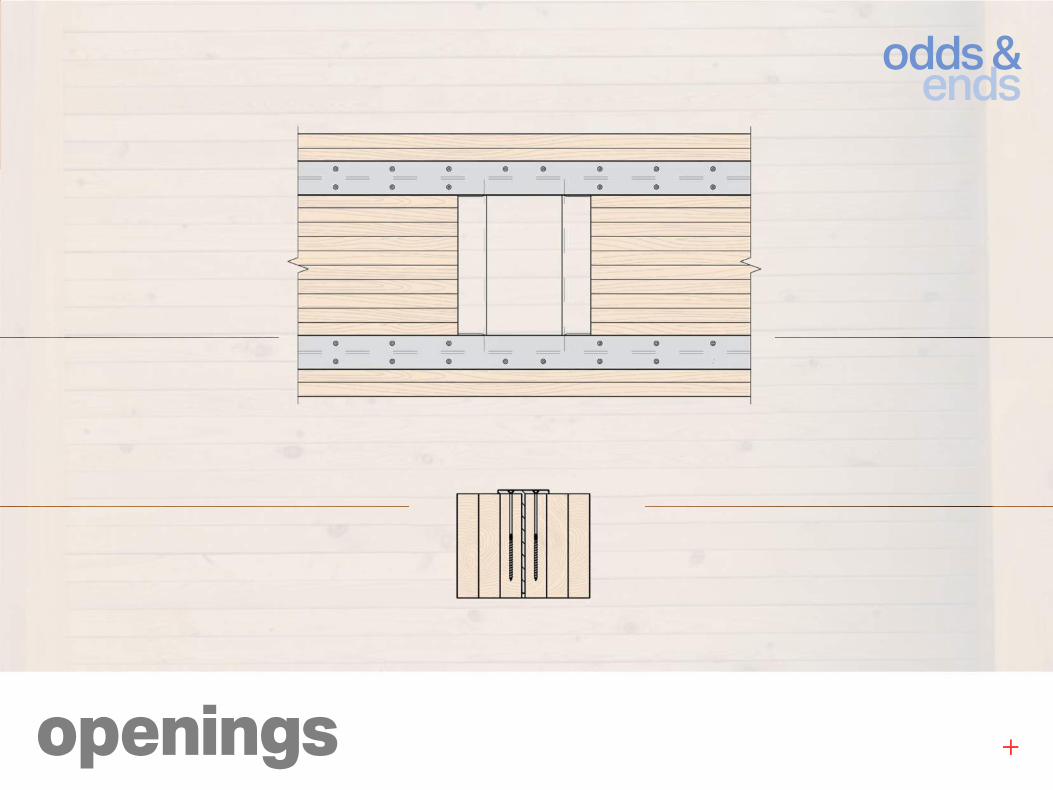
openings
odds &ends
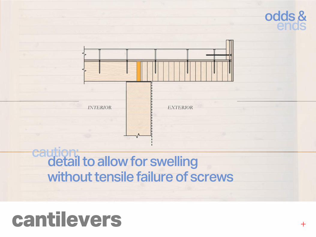
cantilevers
odds &ends
caution:detail to allow for swellingwithout tensile failure of screws
specs
odds &ends
common “holes”:mockup requirements
shop drawings (joint layouts)
weather protection plan
fabrication and erection tolerances
sealers and finishes

thankyou
This concludes the American Institute of Architects
Continuing Education Systems Course
Contact Us:
11th Floor, 41 East 11th St.New York, NY 10003
[email protected] www.fastepp.com Tel: 212.905.8999