Embed Size (px)
Citation preview

1 / 4
Name: Data logger Type: MacREJ 5
Installation manual Document edition: 0001 / June 2018
BASICS
MacREJ 5 data logger is intrinsically safe, explosion proof device. Can be installed in explosive hazardous zones 0, 1 and 2. Ex marking: II 1G Ex ia IIb T4 Ga.
Minimum requirements for improving the safety and health protection of workers potentially at risk from explosive atmospheres are prescribed in Directive 1999/92/EC of the European Parliament and
of the Council of 16 December 1999 (ATEX 137 'Worker Protection Directive').
To keep declared IP66 rating it is highly recommended to use proper cables' diameters inserted
through the cable glands, proper tightening the glands and front cover. In some specific conditions polycarbonate housing can keep the electrostatic load ready to ignite. It is not allowed to install the device in environment conducive to gathering electrostatic loads on housing.
Clean the product only using wet tissue.
MECHANICAL ASSEMBLY
Firstly place the data logger stably on surface considering given dimensions. MacBAT IV installation
kit can be used as well for MacREJ 5. When data logger is equipped with internal pressure sensors, lead the
probe pipes to pressure gathering point. When it is equipped with external pressure sensors, place them
directly in pressure gathering point. It is recommended to install the three-way valves between pressure
sensor and pipeline. Place the temperature sensor in dedicated socket.

2 / 4
WIRES PREPARATION
It is highly advised to use wire cables of 0,25-0,75mm2 intersection according to cable glands
diameters. Wires preparation is presented in the pictures below.
1 - insulated sleeves, 2 - wires, 3 - foil, 4 - shield, 5 - cable, 6 - gland ring, 7 - gland seal, 8 - gland nut
Remove the plug from the cable gland. Prepare the wire according to the picture above. Roll over the
cable shield outside on the insulation. Slide the ring (6) on the shield. Insert prepared cables through proper
cable glands. Cable glands are prepared for grounding pulse cables' shields.
It is highly recommended to use blue-insulated cables. Used cables must fulfil the
requirements of B-type cables according to EN 60079-14 standard. Especially: wires
insulation must handle the 500V AC testing voltage.
Intrinsically safe circuits must be lead separately to the non-intrinsically. Cables must be attached
rigidly to avoid risk of mechanical damage.
Digital inputs - LF, binary, NAMUR:
• LIYCY 2x0,25mm2 - maximum length 10m
• LIYCY 4x0,50mm2 - maximum length 10m
External power supply, modem supply, serial transmission ports, digital outputs:
• LIYCY 2-10x0,5mm2 - maximum length 150m.
• LIYCY 6-10x0,5mm2 - maximum length 200m
Paired cables:
• LIYCY-P 2..5x2x0,34mm2 - maximum length 100m
• LIYCY-P 2..5x2x0,50mm2 - maximum length 150m
• LIYCY-P 2..5x2x0,75mm2 - maximum length 200m
Required wires amount:
• 2 wires - only data logger and modem power supply - on-line work
• 4 wires - data logger and modem power supply, transmission on one serial port
• 6 wires - data logger and modem power supply, transmission on both serial ports
• 7-10 wires - power supply, serial transmission and digital outputs
EXTERNAL CIRCUITS CONNECTION
Previously prepared wires ended with insulated sleeves must be connected to the terminals. When
inserted, cable should clip automatically. Pull the cable gently to check if it is connected well.
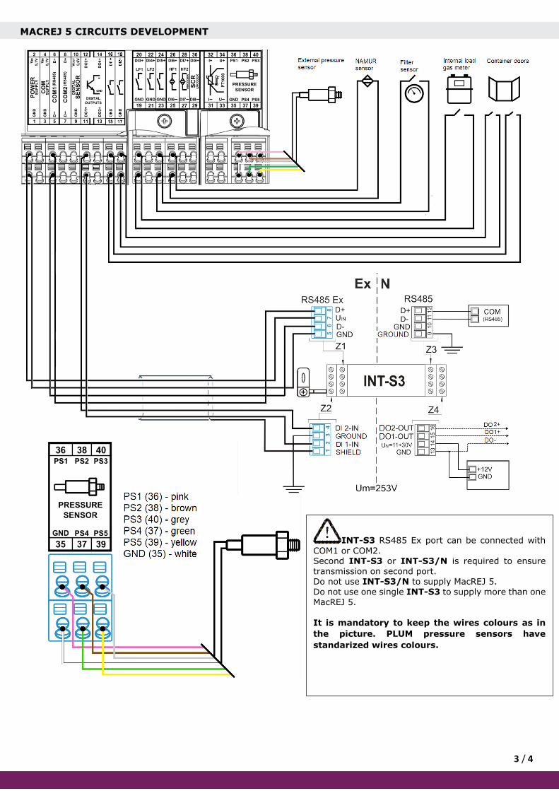
Next page presents diagram of MacREJ 5 development: INT-S3 transmission interface, signalling
circuits, external pressure sensors.
3 / 4
MACREJ 5 CIRCUITS DEVELOPMENT
INT-S3 RS485 Ex port can be connected with
COM1 or COM2. Second INT-S3 or INT-S3/N is required to ensure transmission on second port. Do not use INT-S3/N to supply MacREJ 5. Do not use one single INT-S3 to supply more than one
MacREJ 5.
It is mandatory to keep the wires colours as in
the picture. PLUM pressure sensors have
standarized wires colours.
4 / 4
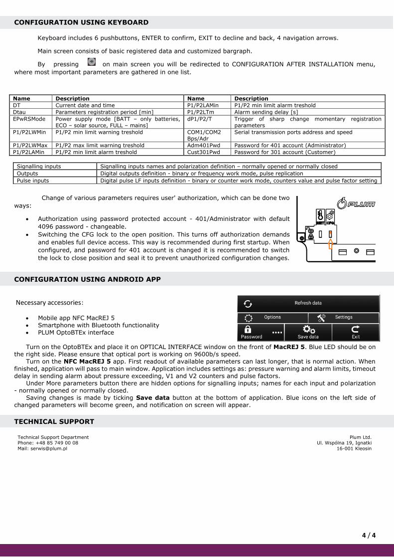
CONFIGURATION USING KEYBOARD
Keyboard includes 6 pushbuttons, ENTER to confirm, EXIT to decline and back, 4 navigation arrows.
Main screen consists of basic registered data and customized bargraph.
By pressing on main screen you will be redirected to CONFIGURATION AFTER INSTALLATION menu,
where most important parameters are gathered in one list.
Name Description Name Description
DT Current date and time P1/P2LAMin P1/P2 min limit alarm treshold
Dtau Parameters registration period [min] P1/P2LTm Alarm sending delay [s]
EPwRSMode Power supply mode [BATT – only batteries, ECO – solar source, FULL – mains]
dP1/P2/T Trigger of sharp change momentary registration parameters
P1/P2LWMin P1/P2 min limit warning treshold COM1/COM2 Bps/Adr
Serial transmission ports address and speed
P1/P2LWMax P1/P2 max limit warning treshold Adm401Pwd Password for 401 account (Administrator)
P1/P2LAMin P1/P2 min limit alarm treshold Cust301Pwd Password for 301 account (Customer)
Signalling inputs Signalling inputs names and polarization definition – normally opened or normally closed
Outputs Digital outputs definition - binary or frequency work mode, pulse replication
Pulse inputs Digital pulse LF inputs definition - binary or counter work mode, counters value and pulse factor setting
Change of various parameters requires user' authorization, which can be done two
ways:
• Authorization using password protected account - 401/Administrator with default
4096 password - changeable.
• Switching the CFG lock to the open position. This turns off authorization demands
and enables full device access. This way is recommended during first startup. When
configured, and password for 401 account is changed it is recommended to switch
the lock to close position and seal it to prevent unauthorized configuration changes.
CONFIGURATION USING ANDROID APP
Necessary accessories:
• Mobile app NFC MacREJ 5 • Smartphone with Bluetooth functionality • PLUM OptoBTEx interface
Turn on the OptoBTEx and place it on OPTICAL INTERFACE window on the front of MacREJ 5. Blue LED should be on
the right side. Please ensure that optical port is working on 9600b/s speed. Turn on the NFC MacREJ 5 app. First readout of available parameters can last longer, that is normal action. When
finished, application will pass to main window. Application includes settings as: pressure warning and alarm limits, timeout delay in sending alarm about pressure exceeding, V1 and V2 counters and pulse factors.
Under More parameters button there are hidden options for signalling inputs; names for each input and polarization - normally opened or normally closed.
Saving changes is made by ticking Save data button at the bottom of application. Blue icons on the left side of changed parameters will become green, and notification on screen will appear.
TECHNICAL SUPPORT
Technical Support Department Phone: +48 85 749 00 08
Mail: [email protected]
Plum Ltd. Ul. Wspólna 19, Ignatki
16-001 Kleosin