Embed Size (px)
Citation preview

LNCT GROUP OF COLLEGES
Name of Faculty: Dr. syed uvaid ullah
Designation: Associate Prof.
Department: EX
Subject: Basic Electrical Engineering
Unit: IV
Topic: D.C. Machine

LNCT GROUP OF COLLEGES
BASIC ELECTRICAL ENGINEERING BT-104 BEEE
NOTES OF UNIT IV D.C. MACHINE
DR. SYED UVAID ULLAH
Q.1 Classify the rotating electrical machine with their applications.
(R.G.P.V. Dec. 2010)
Ans. Basically electrical machine is two types
(1) Static Machine
(I) Transformer
(2) Rotating machine
(II) D.C. Machine
(i) D.C. Generator
(ii) D.C. Motor
(III) A.C. Machine
(i) Synchronous Machine
(A) Synchronous Generator/Motor
(a) Single Phase
(b) Three phase
(ii) Asynchronous Machine
(A) Induction Generator/Motor
(a) Single Phase
(b) Three phase
(i) Static Machine-
(a) Transformer- Transformer is a static device because it has no rotating part. Transformer is
an electromagnetic device which works on faraday’s law of electromagnetic induction.
Application- Industrial Machineries, Manufacturing Industry, Transformer used to provide
required voltage level, Electrical Appliances etc.
(ii) D.C. Machines are of three types
(a) D.C. Series Machine- When field winding and armature winding are
connected in series so is called D.C. series machine-
Application- Industrial uses are hoists, cranes, trolly cars, conveyors, elevators, air
compressors, vacuum cleaners, sewing machines etc.
(b) D.C. shunt machine- When field winding and armature winding are connected
in parallel so is called D.C. series machine.
Application-Centrifugal Pumps, Blowers, Conveyors, Lifts
(c) D.C. compound machine- D.C. compound machine is combination of both
series and shunt D.C. machine. One field winding is connected in series with armature and
second field winding is connected in parallel with armature.

LNCT GROUP OF COLLEGES
Application- A compound motor is used in Conveyors, Elevators, Rolling Mills,
Heavy Planners, Presses, Shears, etc
(iii) A.C. Machines are of two types-
(a) Synchronous Machine- Synchronous motors are a doubly excited machine, two
electrical inputs are provided to it. The rotor carrying dc supply also produces a constant flux.
The main part of synchronous machine is stator and rotor there are two types of rotor used
(i) Salient Pole Type
(ii) Cylindrical Type (Non- Salient Pole)
Application- Robot actuators. Ball mills, clocks, record player.
(ii) Induction motor - An induction motor also known as an asynchronous motor.
Induction motors are referred to as ‘asynchronous motors’ because they operate at a speed
less than their synchronous speed. Induction motor has two main part first is stator which is
stationary and second is rotor is called rotating part.
Application- Induction motors are used in conveyors, cranes, pumps, elevators and
compressors.
Q.2 Write the necessity and material used for the following in a D.C. machine-
(i) Commutator (ii) Brush (R.G.P.V. Dec. 2014)
Ans. Commutator- A Commutator is a electrical switch in specific types of electric
motors and electrical generators that once in a while reverses the current direction between
the rotor and the external circuit. The windings on the armature are connected to the
Commutator segments.
Commentators are used in direct current (D.C.) machines reversing the direction of
the current with each half turn, serving as a mechanical rectifier to convert the alternating
current from the windings to unidirectional direct current in the external load circuit. It is of
cylindrical structure it is built up of wedge shaped segment of high conductivity. Brushes
mounted on Commutator surface for collection of current from the armature conductors
Brushes- Brushes are made of carbon or electrographite material this material is used to
avoid wear and tear of Commutator. The function of brushes is to collect the current from
Commutator. Brushes are generally rectangular in shape. They are housed in brush holder
Q.3 Describe the construction details of a D.C. Machine giving suitable diagram.
(R.G.P.V. Dec. 2013)
OR
Write down the constructional features of a D.C. machine with neat and suitable
diagrams.
(R.G.P.V. June 2016)
OR
Describe D.C. machine with neat sketches in viewing of main parts and constructional
details.
R.G.P.V. Dec. 2016, 2017)
OR
Name the main parts of a D.C. machine and indicate their functions.
(R.G.P.V. Dec. 2015)
LNCT GROUP OF COLLEGES
Ans. Every rotating machine has two important part first is stationary part that is called stator
and second is rotating part that is called rotor. In case of D.C. machine field winding is on the
stator and armature winding is on the rotor.
The main part of D.C. machine
(i) Yoke- yoke is an outer frame of D.C. machine which consist of unlaminated
ferromagnetic material. It provides mechanical support to the inner part of machine. It
provides a path for magnetic flux. The yoke is prepared of cast iron for smaller machine and
it is made of cast steel for larger machines.
(ii) Pole – Each pole divided into two parts
(a) Pole core
(b) Pole shoe
(iii) Pole core- Field winding is mounted on the pole core which is necessary to produce the
flux. They extend out the magnetic flux over the armature outside edge more uniformly. Pole
core is made of cast iron or cast steel. Pole core are fixed to the magnetic frame or yoke by
bolts or by weld.
(iv) Pole shoes- Pole shoes are made of cast iron or cast steel. Pole shoes have larger cross
sectional area as compare to pole core which provide less reluctance for magnetic path. The
front segment of pole is of larger cross section area and known as the pole shoe or pole face.
The pole shoe provide the following serves
(a) Pole shoe makes the air gap flux uniform.
(b) Pole shoe provide mechanical support to the field winding
(c) Pole shoe decrease the reluctance of the magnetic path.
(v) Field winding- field winding is called exciting winding field winding is made from
copper material. When D.C current is passed through the field winding it magnetizes the
poles which create the required flux. The field coils of all the poles are associated in series in
such a way that when current through them the nearby poles reach opposite polarity.
(vi) Armature – Armature further divided into two parts namely.
(a) Armature core- it is cylindrical in shape and mounded on the rotating shaft. It
consists of slots on its circumference and the air ducts to allow the air flow from beginning to
end armature which serves cooling purpose. It serves for housing armature coils in the slots
and given that the low reluctance path to the magnetic flux. Since armature is a rotating part
of the machine. To minimize hysteresis losses silicon steel material is used for its
construction.
(b) Armature winding- the insulated conductors housed in the armature slots are
properly connected. The armature winding is main part of D.C. machine. Armature winding
is the interconnection of the armature conductor. In case of generator when armature is
rotated magnetic flux get cut by armature conductor and an e.m.f. get induced in them. On the
basis of connection armature winding is two types (i) Lap winding (ii) Wave winding.
(vii) Commutator- A Commutator is a electrical switch in specific types of electric
motors and electrical generators that once in a while reverses the current direction between
the rotor and the external circuit. The windings on the armature are connected to the
Commutator segments.
Commentators are used in direct current (D.C.) machines reversing the direction of
the current with each half turn, serving as a mechanical rectifier to convert the alternating
current from the windings to unidirectional direct current in the external load circuit. It is of
cylindrical structure it is built up of wedge shaped segment of high conductivity. Brushes
mounted on Commutator surface for collection of current from the armature conductors

LNCT GROUP OF COLLEGES
(viii) Brushes- Brushes are made of carbon or electrographite material this material is
used to avoid wear and tear of Commutator. The function of brushes is to collect the current
from Commutator. brushes are generally rectangular in shape. They are housed in brush
holder.
(ix) Bearing - The most important purpose of a bearing is to support the rotating parts and
to permit its smooth motion with minimum friction. For medium size machines roller bearing
may be used at the driving end and ball bearing at the non driving end. For small machines
ball bearing are used at both ends. The main function of the bearing is to reduce friction
between rotating part and stationary part.
(x) Shaft – The shaft is used to transfer mechanical power from one machine to other
machine. The rotating part of D.C. machine like armature, Commutator, cooling fan are
mounted on the shaft.
Q. 5 Classify self excited D.C. motor. (R.G.P.V. Dec. 2014)
Ans. Self excited D.C. motor can be further classified as follow
(i) Series Motor – In case of D.C. series motor field winding is connected in series with
armature winding.
current Load IL
current Armature Ia
currentwindingFieldSeriesIse
voltageSupply V
e.m.f.BackEb
ResistanceArmatureRa
ResistancewindingFieldSeriesR se
brushesacrossdropVoltageVb
seaL III
bseaab V2)R(RIEV
(ii) Shunt Motor – In case of D.C. shunt motor field winding is connected in parallel with
armature winding.
current Load IL
current Armature Ia
currentwindingFieldShuntIsh
voltageSupply V
e.m.f.BackEb
ResistanceArmatureRa
ResistancewindingFieldSeriesR se
brushesacrossdropVoltageVb
shaL III
baab V2RIEV
(iii) Compound Motor – D.C. compound machine is combination of both series and shunt
D.C. machine. One field winding is connected in series with armature and second field
LNCT GROUP OF COLLEGES
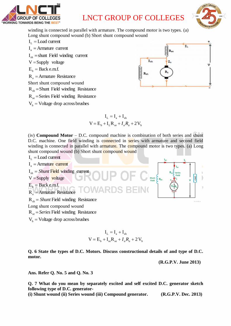
winding is connected in parallel with armature. The compound motor is two types. (a)
Long shunt compound wound (b) Short shunt compound wound
current Load IL
current Armature Ia
currentwindingFieldshuntIsh
voltageSupply V
e.m.f.BackEb
ResistanceArmatureRa
Short shunt compound wound
ResistancewindingFieldShuntR sh
ResistancewindingFieldSeriesR se
brushesacrossdropVoltageVb
shaL III
bseLb V2RIEV aaRI
(iv) Compound Motor – D.C. compound machine is combination of both series and shunt
D.C. machine. One field winding is connected in series with armature and second field
winding is connected in parallel with armature. The compound motor is two types. (a) Long
shunt compound wound (b) Short shunt compound wound
current Load IL
current Armature Ia
currentwindingFieldIsh Shunt
voltageSupply V
e.m.f.BackEb
ResistanceArmatureRa
ResistancewindingFieldRsh Shunt
Long shunt compound wound
ResistancewindingFieldR se Series
brushesacrossdropVoltageVb
shaL III
bseseb V2RIEV aaRI
Q. 6 State the types of D.C. Motors. Discuss constructional details of and type of D.C.
motor.
(R.G.P.V. June 2013)
Ans. Refer Q. No. 5 and Q. No. 3
Q. 7 What do you mean by separately excited and self excited D.C. generator sketch
following type of D.C. generator-
(i) Shunt wound (ii) Series wound (iii) Compound generator. (R.G.P.V. Dec. 2013)
LNCT GROUP OF COLLEGES
OR
Classify D.C. machines and explain them briefly. (R.G.P.V. June 2014)
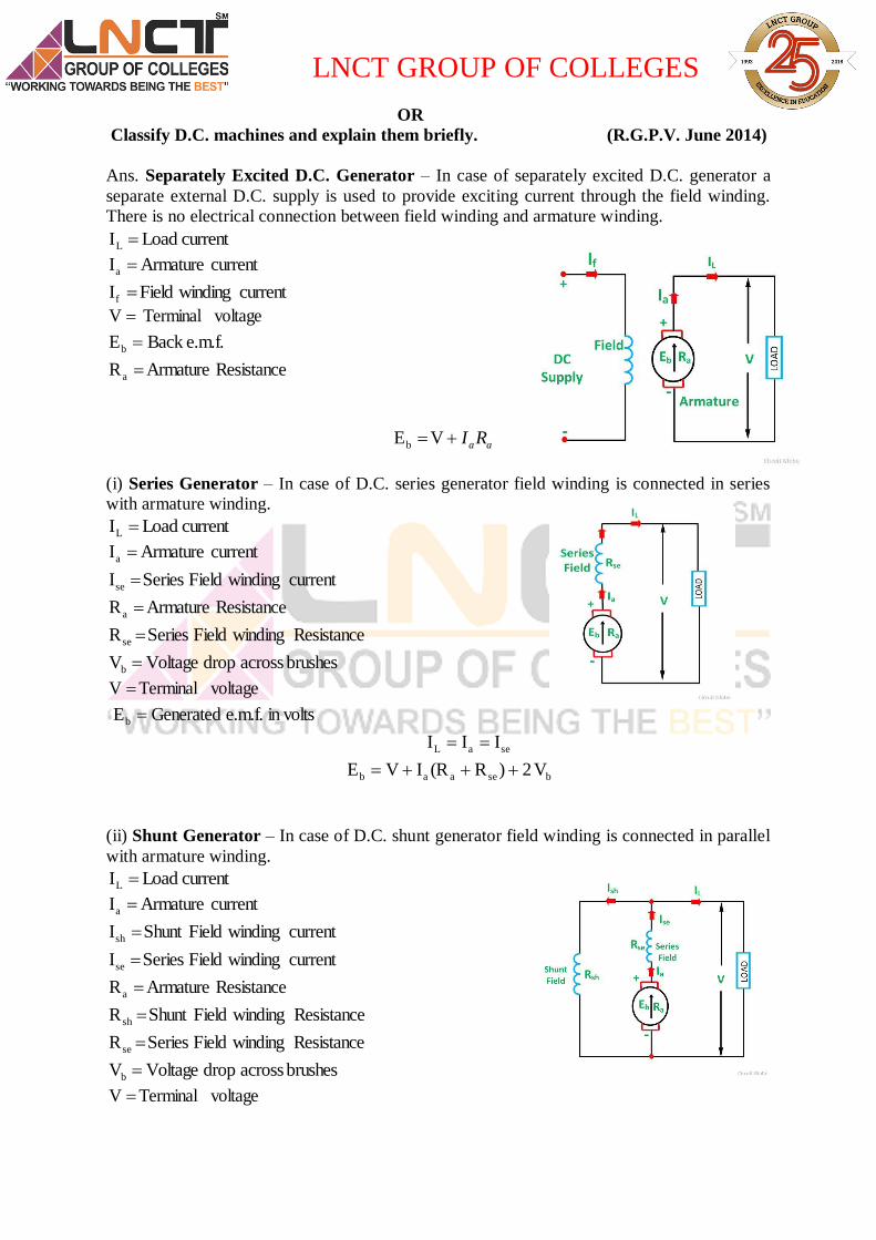
Ans. Separately Excited D.C. Generator – In case of separately excited D.C. generator a
separate external D.C. supply is used to provide exciting current through the field winding.
There is no electrical connection between field winding and armature winding.
current Load IL
current Armature Ia
currentwindingFieldIf
voltage Terminal V
e.m.f.BackEb
ResistanceArmatureRa
aaRIVEb
(i) Series Generator – In case of D.C. series generator field winding is connected in series
with armature winding.
current Load IL
current Armature Ia
currentwindingFieldSeriesIse
ResistanceArmatureRa
ResistancewindingFieldSeriesR se
brushesacrossdropVoltageVb
voltage TerminalV
in volts e.m.f.GeneratedEb
seaL III
bseaab V2)R(RIVE
(ii) Shunt Generator – In case of D.C. shunt generator field winding is connected in parallel
with armature winding.
current Load IL
current Armature Ia
currentwindingFieldShuntIsh
currentwindingFieldSeriesIse
ResistanceArmatureRa
ResistancewindingFieldShuntR sh
ResistancewindingFieldSeriesR se
brushesacrossdropVoltageVb
voltage TerminalV

LNCT GROUP OF COLLEGES
in volts e.m.f.GeneratedEb
shaL III
baab V2RIE seseRIV
(iii) Compound Generator – D.C. compound machine is combination of both series and
shunt D.C. machine. One field winding is connected in series with armature and second field
winding is connected in parallel with armature. The compound generator is two types. (a)
Long shunt compound wound (b) Short shunt compound
wound
current Load IL
current Armature Ia
currentwindingFieldShuntIsh
currentwindingFieldSeriesIse
ResistanceArmatureRa
ResistancewindingFieldShuntR sh
ResistancewindingFieldSeriesR se Short shunt compound
wound
brushesacrossdropVoltageVb
voltage TerminalV
in volts e.m.f.GeneratedEb
shaL III
bseseb V2RIEV aaRI
(iv) Compound Generator – D.C. compound machine is combination of both series and
shunt D.C. machine. One field winding is connected in series with armature and second field
winding is connected in parallel with armature. The compound generator is two types. (i)
Long shunt compound wound (ii) Short shunt compound wound
current Load IL
current Armature Ia
currentwindingFieldShuntIsh
voltageSupply V
e.m.f.BackEb
ResistanceArmatureRa
ResistancewindingFieldShuntR sh
ResistancewindingFieldSeriesR se
brushesacrossdropVoltageVb
Long shunt compound wound
shaL III
bseseb V2RIEV aaRI

LNCT GROUP OF COLLEGES
Q.8 Write the basic principle of operation and working of D.C. motor.
(R.G.P.V. June 2007, 2008, July 2008)
OR
Explain working principle of D.C. motor with necessary diagram. (R.G.P.V. June 2017)
OR
With a neat diagram explain the working and principle of D.C. motor.
(R.G.P.V. May 2019)
Ans. A machine which converts D.C. electrical power into mechanical power is called D.C.
motor. This mechanical energy is utilized to drive mechanical load coupled to the shaft of the
motor. Construction of D.C. motor is same as D.C. generator. The principle of operation of a
D.C. motor can be declared in a single statement as when a current carrying conductor is
placed in a magnetic field a mechanical force is occurrence by it. The direction of this force is
definite by Fleming’s left hand rule. If conductors is free to rotate then it starts rotation in the
direction of force.
F = BIl sin𝜃 Newton
B = Flux density in wb/m2
I = Current in Amp.
l = length of conductor in meter
𝜃 = angle between field and conductor
For simplicity, consider that the armature of D.C. motor has only one coil which is located
between the magnetic field shown in the figure A. When the D.C. supply is connected to the
armature coil the current flowing through it. Which build up their own field around the coil as
shown in Figure B
By the interaction of the two fields produces by the pole and the magnet, a resultant field set
up across the conductor. The resultant field has a propensity to recover its original position,
i.e. in the axis of the main field. The fields apply the force at the ends of the conductor, and
consequently the coil starts rotating.
Q.9 Explain the working principle and construction of D.C. Machine.
(R.G.P.V. Dec. 2010)
OR
LNCT GROUP OF COLLEGES
Explain the constructional and operational feature of a D.C. machine with the
help of neat diagram.
(R.G.P.V. Dec. 2012)
OR
Sate basic principle of D.C. motor. Draw diagram of D.C. machine and name its parts
(R.G.P.V. May 2018)
Ans. Refer Q. No. 8 & 3
Q.10 Explain constructional classification and working principle of D.C. Machine.
(R.G.P.V. Nov. 2018)
Ans. Refer Q. No. 3 , 5 & 8
Q.11 Drive the expression of generated voltage in D.C. machine.
(R.G.P.V. Dec. 2006, 2007-2011)
OR
Drive e.m.f equation of a D.C. motor/generator.
OR
Develop an e.m.f. equation for generator. (R.G.P.V. Dec. 2016, 2017)
Ans. E.M.F. Equation of D.C. generator:
A
NPPE
60
P = Number of poles of generator
= Flux produced by each pole in Weber
N = Speed of armature in R.P.M.
Z = Total number of armature conductor
A = Number of parallel path
A = P For lap type of winding
A = 2 For wave type of winding
Let E is the generated e.m.f. in the armature according to faraday’s law of electromagnetic
induction.
T = number of turns
dt
dTE
If number of turns T = 1 then
dt
dE
Now consider one revolution of conductor. In one revolution conductor will cut total flux
produced by all the poles = P
While time required to complete one revolution is 60/N seconds as speed in R.P.M.
6060
NP
N
PE
If total number of conductor = Z
Number of parallel path = A

LNCT GROUP OF COLLEGES
Hence Z/A number of conductors are always in series and e.m.f. remains same across
all the parallel paths.
The e.m.f. equation of a D.C. generator A
NZP
A
ZNPNPE
606060
Q. 12 Give reasons why starting current is high in D.C. motor? (R.G.P.V. June 2012)
Why you need a starter to start a D.C. motor? (R.G.P.V. June 2015)
Ans. – A D.C. motor generate back e.m.f. which oppose the supply voltage as per Lenz’s law
so starting current reduce drawn by motor. At the time of starting motor is stationary mode
and there is no back e.m.f in the armature. If motor is directly connect to supply voltage
armature draw a heavy current because armature has small resistance and no back e.m.f. As
an example 3 H.P, 200 V shunt motor has a full load current of 10A and armature resistance
of about 0.5 ohm. If this motor is directly switched on to supply, so armature current is equal
to A4005.0
200 which is 40 times greater then the full load current. If speed of D.C. motor is
high so back e.m.f is high and armature current will low. If speed of D.C. motor is low so
back e.m.f is low and armature current will high which develop motor torque.
Q. 13 What do you understand by commutation? (R.G.P.V. Jan/Feb. 2007)
Ans- Commutation mean reversal of armature current from its positive value to same
negative value by means of brushes and Commutator bars. In D.C. motors commutation is
easy to identify with as brushes contact a Commutator and switch the current as the motor
moves.
When current is functional to the motor, the accurate winding is energized by virtue
of the brushes being in contact with the Commutator at the point where the winding
terminates. As the motor moves, the next coil in the sequence will be energized. For
collecting and feeding the electrical supply carbon or electrographite brushes are all time
fitted on the Commutator surface. These brushes touch the Commutator surface and do not
rotate with Commutator. With the help of commutation method induced e.m.f. in the
armature conductors of a D.C. generator can be made unidirectional.
Q.14 what is a function of back e.m.f. in a D.C. motor? (R.G.P.V. Jan/Feb. 2007)
OR
Give reason why induced e.m.f in a D.C. motor is called back e.m.f.
(R.G.P.V. Jan. /Feb. 2007)
Ans.- D.C. motor have two important part stator and armature. When motor armature rotates
then armature conductors cut the magnetic flux. An e.m.f. induced in armature conductors by
faraday’s law of electromagnetic induction. Whose direction as found by Fleming’s right
hand rule the polarity of this induced e.m.f. is such that it can oppose the applied voltage in
the armature circuit.
Because of it opposite direction it is called back e.m.f. and denoted by Eb. Mainly it
obtain generated by the generating action which we have observe previous in case of
generators. So it magnitude can be determined by the e.m.f. equation which is derived earlier
LNCT GROUP OF COLLEGES
voltsA
NZPEb
60
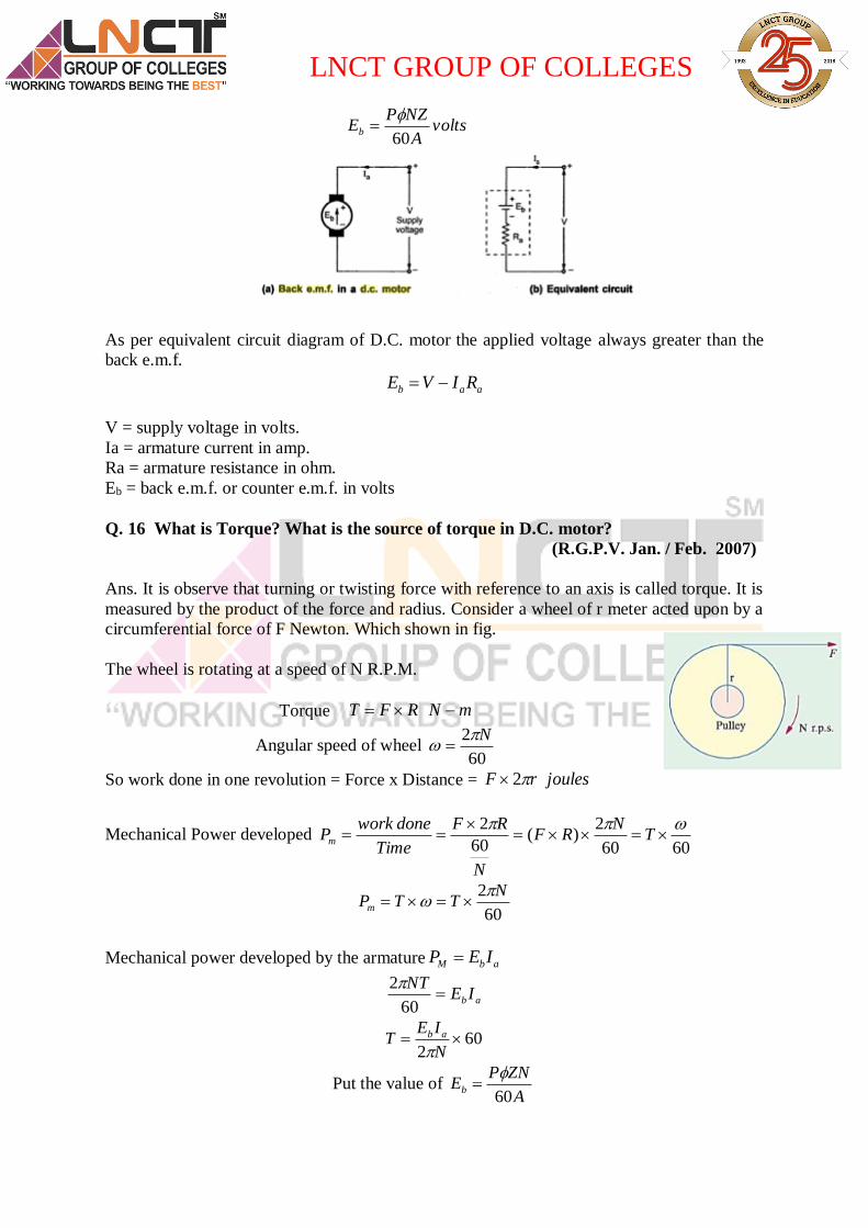
As per equivalent circuit diagram of D.C. motor the applied voltage always greater than the
back e.m.f.
aab RIVE
V = supply voltage in volts.
Ia = armature current in amp.
Ra = armature resistance in ohm.
Eb = back e.m.f. or counter e.m.f. in volts
Q. 16 What is Torque? What is the source of torque in D.C. motor?
(R.G.P.V. Jan. / Feb. 2007)
Ans. It is observe that turning or twisting force with reference to an axis is called torque. It is
measured by the product of the force and radius. Consider a wheel of r meter acted upon by a
circumferential force of F Newton. Which shown in fig.
The wheel is rotating at a speed of N R.P.M.
Torque mNRFT
Angular speed of wheel 60
2 N
So work done in one revolution = Force x Distance = joulesrF 2
Mechanical Power developed 6060
2)(
60
2
T
NRF
N
RF
Time
doneworkPm
60
2 NTTPm
Mechanical power developed by the armature abM IEP
abIENT
60
2
602
N
IET ab
Put the value of A
ZNPEb
60

LNCT GROUP OF COLLEGES
A
ZIP
NA
ZNIPT aa
260
260

LNCT GROUP OF COLLEGES
NUMERICAL PROBLEMS
Problem No.1 A six pole lap wound D.C. generator has 720 conductors a flux of 40 mwb per pole is driven at 400 rpm. Find the generator emf. (R.G.P.V. June-2017) Solution- Given Data- No. of poles P = 6 For lap winding A = P Speed of motor N = 400 r.p.m.
Flux wbmwb 3104040
Z = 720
Find – Generated emf VA
zNPEg 192
660
72010406400
60
3
Problem2- calculate the generated emf of a 8 pole wave wound D.C. generator which is having 720 conductors a flux per pole is 40 mwb and is driven at 400 rpm. (R.G.P.V. May-2018) Solution- Given Data- No of poles P = 8 No of conductor Z = 720
Flux per pole wbmwb 3104040
No of parallel path for wave winding A = 2
Find - .768260
72010408400
60
3
ansVA
zNPEg
Problem3- A shunt generator delivers 50 kw at 250 V and 400 r.p.m. The armature and field resistance are 0.02 ohm and 50 ohm respectively. Calculate the speed of the machine running as shunt motor and taking 50 KW input at 250 V. Given Data-
Power of motor & generator wkwP 3105050
Supply voltage & terminal voltage V = 250 V Speed of motor N1 = 400 R.P.M.
Armature resistance 02.0aR
Field Resistance 50fR
Find – Speed of Machine 2
1
1
2
1
2
E
E
N
N
12& soconstataregeneratormotorofcurrentfieldshunt
...41.3874001.254
1.2461
1
22 MPRN
E
EN

LNCT GROUP OF COLLEGES
550
250,200
250
1050
2055200
0,02.0,250
1.25402.0205250
...
...400
3
1
1
1
sh
shL
shLa
a
aa
R
VI
V
PI
IIIcurrentArmature
dropbrushRV
E
dropbrushRIVEfmeGenerator
mprN
550
250,200
250
1050
1955200
0,02.0,250
1.246002.0195250
...
3
2
2
sh
shL
shLa
a
aa
R
VI
V
PI
IIIcurrentArmature
dropbrushRV
E
dropbrushRIVEfmeGenerator
Problem.4- A 30 kw, 33 V D.C. shunt generator has armature and field resistance of 0.05 ohm and 100 ohm respectively. Calculate the total power developed by the armature when it delivers full output power. (R.G.P.V. MAY 2019) Given Data- Power P = 30 kw Terminal voltage V= 33 V
Armature resistance ohmRa 05.0
Field resistance ohmR f 100
Find-
Total Power Developed by Generator kwIEP ag 36.7118.7136242.90947.78
33.0100
33,09.909
33
1030
42.90933.009.909
3
sh
shL
shLa
R
VI
V
PI
AIII


![[IJETA-V3I2P10]:Muhammad Tahir, Fazlullah Khan, Syed Roohullah Jan, Izaz Ahmad Khan, Nazia Azim, Farman Ullah](https://img.pdfslide.net/doc/110x75/577c7ec21a28abe054a2578c/ijeta-v3i2p10muhammad-tahir-fazlullah-khan-syed-roohullah-jan-izaz-ahmad.jpg)