Embed Size (px)
Citation preview
TENDER DOCUMENT
FOR
SUPPLY, INSTALLATION & COMMISSIONING
OF 1NO 8 PASSENGER LIFT IN ALLAHABAD BANK
RESIDENTIAL BUILDING AT VIVEK VIHAR, DELHI
Architect M/S. Mriduanjali Architects & Engineers Pvt LtdC-1, Sector-20, Noida-201301, Phone +91120 4323064Email: [email protected]

CONTENTSDESCRIPTION .
NOTICE INVITING TENDER...................................................................................
SPECIAL CONDITIONS OF CONTRACT......................................................................
TECHNICAL SPECIFICATIONS.................................................................................
LIFT MACHINE AND CONTROLLER....................................................................................................
ASSOCIATED ELECTRICAL WORKS.....................................................................................................
MAINTENANCE SERVICES...............................................................................................................
TESTING OF LIFT INSTALLATION.......................................................................................................
PROVISION FOR THE DISABLED AND HANDICAPPED.............................................................................
TECHNICAL PARAMETERS....................................................................................
FINANCIAL BID......................................................................................................................................
ANNEXTURE--A.................................................................................................
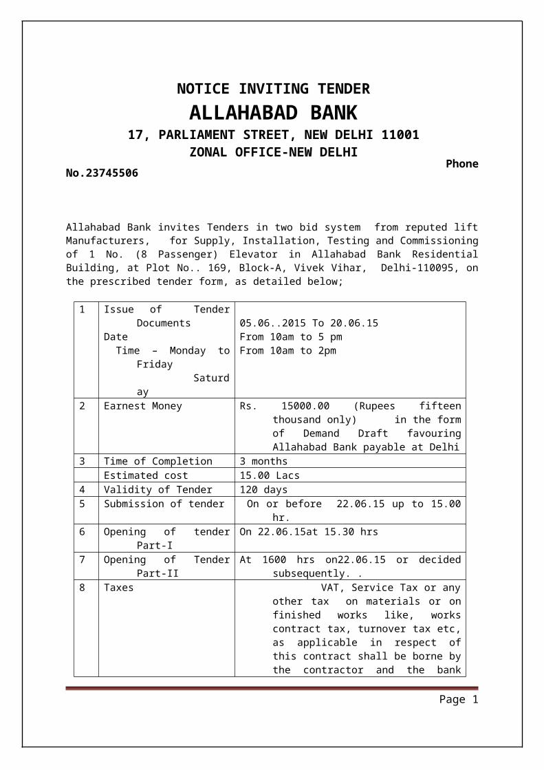
NOTICE INVITING TENDERALLAHABAD BANK
17, PARLIAMENT STREET, NEW DELHI 11001ZONAL OFFICE-NEW DELHI
Phone No.23745506
Allahabad Bank invites Tenders in two bid system from reputed lift Manufacturers, for Supply, Installation, Testing and Commissioning of 1 No. (8 Passenger) Elevator in Allahabad Bank Residential Building, at Plot No.. 169, Block-A, Vivek Vihar, Delhi-110095, on the prescribed tender form, as detailed below;
1 Issue of Tender DocumentsDate Time – Monday to Friday Saturday
05.06..2015 To 20.06.15 From 10am to 5 pm From 10am to 2pm
2 Earnest Money Rs. 15000.00 (Rupees fifteen thousand only) in the form of Demand Draft favouring Allahabad Bank payable at Delhi
3 Time of Completion 3 monthsEstimated cost 15.00 Lacs
4 Validity of Tender 120 days 5 Submission of tender On or before 22.06.15 up to 15.00 hr.6 Opening of tender Part-I On 22.06.15at 15.30 hrs 7 Opening of Tender Part-II At 1600 hrs on22.06.15 or decided subsequently. . 8 Taxes VAT, Service Tax or any other tax on
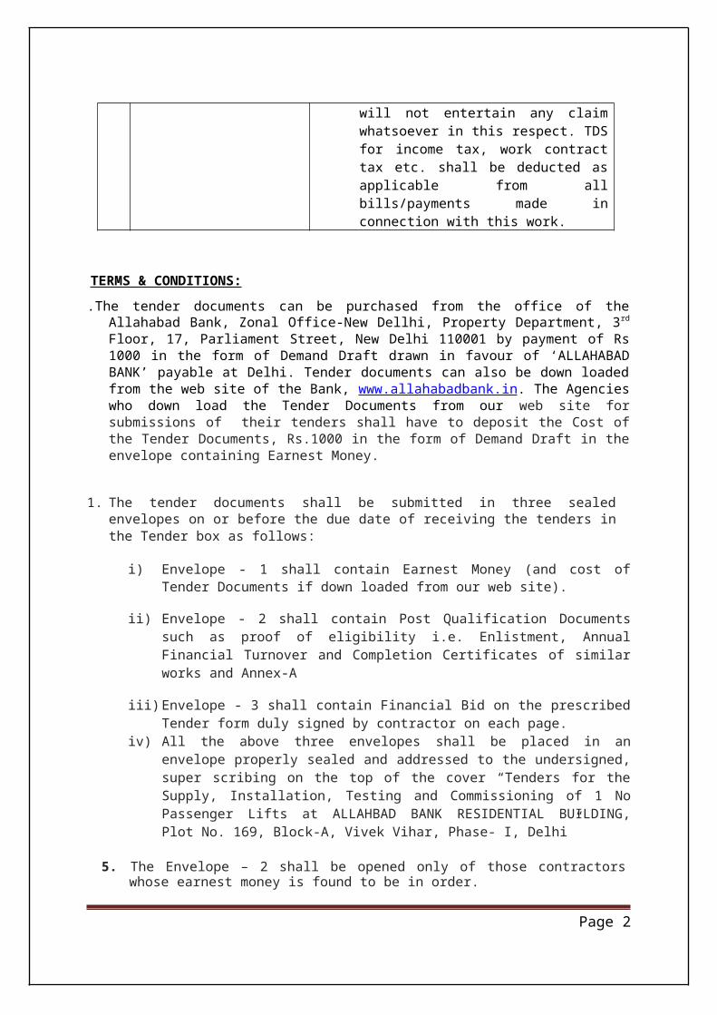
materials or on finished works like, works contract tax, turnover tax etc, as applicable in respect of this contract shall be borne by the contractor and the bank will not entertain any claim whatsoever in this respect. TDS for income tax, work contract tax etc. shall be deducted as applicable from all bills/payments made in connection with this work.
TERMS & CONDITIONS:
.The tender documents can be purchased from the office of the Allahabad Bank, Zonal Office-New Dellhi, Property Department, 3rd Floor, 17, Parliament Street, New Delhi 110001 by payment of Rs 1000 in the form of Demand Draft drawn in favour of ‘ALLAHABAD BANK’ payable at Delhi. Tender documents can also be down loaded from the web site of the Bank, www.alla-habadbank.in. The Agencies who down load the Tender Documents from our web site for sub-missions of their tenders shall have to deposit the Cost of the Tender Documents, Rs.1000 in the form of Demand Draft in the envelope containing Earnest Money.
1. The tender documents shall be submitted in three sealed envelopes on or before the due date of receiving the tenders in the Tender box as follows:
Page 1
i) Envelope - 1 shall contain Earnest Money (and cost of Tender Documents if down loaded from our web site).
ii) Envelope - 2 shall contain Post Qualification Documents such as proof of eligibility i.e. Enlistment, Annual Financial Turnover and Completion Certificates of similar works and Annex-A
iii) Envelope - 3 shall contain Financial Bid on the prescribed Tender form duly signed by contractor on each page.
iv) All the above three envelopes shall be placed in an envelope properly sealed and ad-dressed to the undersigned, super scribing on the top of the cover “Tenders for the Sup-ply, Installation, Testing and Commissioning of 1 No Passenger Lifts at ALLAHBAD BANK RESIDENTIAL BUILDING, Plot No. 169, Block-A, Vivek Vihar, Phase- I, Delhi”
5. The Envelope – 2 shall be opened only of those contractors whose earnest money is found to be in order.
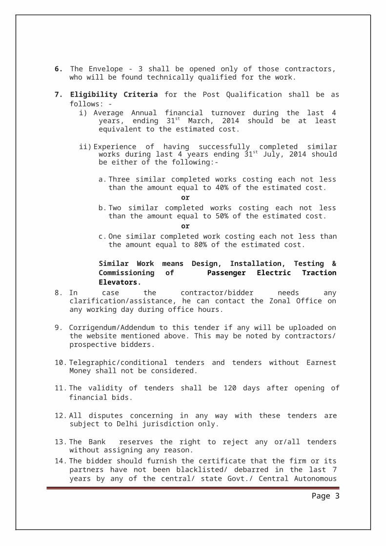
6. The Envelope - 3 shall be opened only of those contractors, who will be found technically qualified for the work.
7. Eligibility Criteria for the Post Qualification shall be as follows: - i) Average Annual financial turnover during the last 4 years, ending 31st March, 2014
should be at least equivalent to the estimated cost.
ii) Experience of having successfully completed similar works during last 4 years end-ing 31st July, 2014 should be either of the following:-
a. Three similar completed works costing each not less than the amount equal to 40% of the estimated cost.
orb. Two similar completed works costing each not less than the amount equal to
50% of the estimated cost. or
c. One similar completed work costing each not less than the amount equal to 80% of the estimated cost.
Similar Work means Design, Installation, Testing & Commissioning of Passenger Electric Traction Elevators.
8. In case the contractor/bidder needs any clarification/assistance, he can contact the Zonal Of-fice on any working day during office hours.
9. Corrigendum/Addendum to this tender if any will be uploaded on the website mentioned above. This may be noted by contractors/ prospective bidders.
10. Telegraphic/conditional tenders and tenders without Earnest Money shall not be considered.
11. The validity of tenders shall be 120 days after opening of financial bids.
12. All disputes concerning in any way with these tenders are subject to Delhi jurisdiction only.
13. The Bank reserves the right to reject any or/all tenders without assigning any reason. 14. The bidder should furnish the certificate that the firm or its partners have not been black-
listed/ debarred in the last 7 years by any of the central/ state Govt./ Central Autonomous
Page 2
body/ Central Public Sector department/ Authority. 15. The bidder should have Service Centre at Delhi
The Dy. General Manager, Allahabad Bank, Zonal Office-New Delhi17, Parliament Street, New Delhi 110001
Page 3
SPECIAL CONDITIONS OF CONTRACT
TENDER DOCUMENT FOR SUPPLY, INSTALLATION, TESTING & COMMISSIONING OF LIFTS
1.1 Tender Document
This tender document, comprising of Notice Inviting Tender, Special Conditions of Contract, Technical Specifications, Schedule of Quantities and tender drawings shall form part of the contract Agreement after award of contract. Work under this contract shall be executed at contract rates as per conditions and specifications stipulated in this tender document except in respect of deviations specifically agreed to before the award of the contract and incorporated in the contract Agreement. In addition, components/materials, which may not be specifically stipulated in the tender document, but which are necessary for satisfactory installation and/or operation of any portion of the work, shall also be provided within the contract rates without any extra cost. Contractor shall carry out and complete the work in all respects to the satisfaction of Owners as per the contract Agreement and as directed by Owners/Consultants and as required.
1.2 Tender Conditions, Specifications and Schedule
Special Conditions of Contract (SCC) shall be read in conjunction with Technical Specifica-tions, Schedule of Quantities, Tender Drawings and any other document forming part of this contract Agreement
For any discrepancy between Technical Specifications and Schedule of Quantities, provision of Schedule of Quantities shall prevail.
Any item shown in Schedule of Quantities and not called for in the Specifications or vice versa shall be provided as if called for in both.
Wherever it is mentioned that the Contractor shall perform certain work or provide certain facilities, it is understood that the Contractor shall do so at his own cost.
Where the Technical Specifications stipulate requirements in addition to those contained in the applicable Indian Standard Specifications/Codes, these additional requirements shall also be satisfied.
1.3 Departures
No deviation from tender conditions shall be acceptable.
1.4 Authorities
The work shall conform to all the provisions of the relevant Government Legislation, Regulations and Bye-laws of the Central/Local Authorities and of the concerned Electricity Supply Authority. The Contractor shall also be responsible for giving all notices required under the said Acts/Regulations/Bye-laws.
Page 4
1.5 Electrical License
The tenderers shall a licensed Electrical Contractor possessing a valid Contractor's license of “A” class in the state, employing licensed supervisors and skilled workers having valid permits as per the regulations of Indian Electricity Rules and local Electrical Inspectors requirements. Copy of Contractor's Electrical license shall be furnished along with the tender.
2. INTENT OF SPECIFICATIONS
It is not the intent of Technical Specifications to completely specify all aspects of design/construction features of equipments and all details of work to be carried out Nevertheless the intent of the Technical Specification is to ensure that the equipments and the work shall fully comply with and conform to the relevant Bureau of Indian Standard Specifications, Codes of Practice, Indian Electricity Act, Indian Electricity Rules and other Statutory Regulations, and other standards as may be applicable and to the best available standards of engineering, design and workmanship. The equipment and work shall perform in manner acceptable to Owners who shall interpret meaning of the applicable Specifications/Codes and shall have the right to reject any equipment or work, which, in their assessment, is not complete to meet the Standard/Code.
3. SITE OF WORK
3.1 Brief description of site
Tenderers are advised to visit the site after taking prior permission from Bank for familiarizing themselves with working conditions available at site as also with the statutory levies and their prevailing quantum payable at site. Contractors shall not be entitled to claim any extra payment on account of lack of such knowledge after award of contract.
3.2 Power Supply System
Entire work shall be suitable for use on 415 volt 3 phase 4 wire supply system with transformer neutral grounded. The rated frequency of the supply system shall be 50 cycles per second.
3.3 Ambient Conditions
All equipments components and materials used in the work shall be suitable for continuous operation/use at rated output with permissible overload at the following extremes of ambient conditions likely to be encountered at site.
Temperature from minimum 0o C to maximum 45o CRelated humidity from minimum 10% RH to maximum 100% RH
Page 5

4. OWNER TO PROVIDE
Owner’s scope of contract shall be restricted to providing the following items free of cost to the Contractor.
Hoistway (with structural openings for doors), Pit and Machine Room. Hook in machine room ceiling slab over the hoist way for hoisting lift equipment Space only for Contractor’s site office/stores for the duration of the contract at location and
of size considered suitable and available with the Owners. Owners reserve the right to pro-vide alternative space for the purpose, if so necessary, during the tenure of the contract.
5. SCOPE OF CONTRACT
Contractor’s scope of the contract shall comprise of providing equipments, components, materials, labour, supervisory staff with infrastructure, T&P, scaffolding, consumables, testing equipment, etc. required for completion of the work as per the contract Agreement and Free Comprehensive Maintenance for one years after completion. Contract Rates shall be deemed to be inclusive of all direct and indirect expenses required to be incurred as per this scope including but not restricted to the costs of the following.
5.1 Items of Work
Design, manufacture, supply, installation, testing and commissioning of Lifts as per Schedule of Quantities.
5.2 Statutory Levies
Statutory levies as applicable as below. Central Sales tax without issue of C-form by Bank. Excise duty/custom duty. Work contract tax Octroi Any other levies. Service Tax.
5.3 Testing
Testing for the various items of equipment shall be performed at the contractor’s cost and test certificate to be furnished by the contractor (for Motor, Machine Break-tests Controller & Steel wire Ropes). If required by the Engineer, the Contractor shall permit the Owner’s authorized representative to be present during any of the tests. After notification to the Owner that the installation has been completed the contractor shall make under the direction and in the presence of the Engineer such test and inspections as have been specified or as the Engineer shall consider necessary to determine whether or not the full intent of the requirements of the plans and specifications have been fulfilled. In case the work does not meet the full intent of the specifications and further tests shall be considered necessary the contractor shall bear all the expenses thereof.
Page 6
5.4 Transportation, Storage, insurance etc.
Loading, transportation and unloading. Protection of stored materials/installed work against damage due to dirt, sun and rain in-
cluding providing tarpaulin/ PVC sheet covers as required. Providing security arrangements/watch and ward for stored materials and installed works to
guard against pilferage/damage. Comprehensive insurance with Owners as beneficiaries against pilferage/damage during
transportation/storage/installation valid till handing over. Third party insurance of adequate amount
5.5 Name plates
Providing engraved anodized aluminium or approved equivalent name plates of suitable sizes on switchboards/panels/equipments etc.
5.6 Civil works, cleaning and painting
5.6.1 Civil Works
All steel items required for installation and operation of Lift System in Pits, Hoist-ways and Machine Rooms.
Minor civil work items required for the work like making chases in walls/ceilings, making holes and openings, providing inserts, grouting etc including making good and painting the civil works.
5.6.2 HousekeepingHousekeeping and clearing of work area during the tenure of contract.
5.6.3 Final PaintingProviding final paint coat to all exposed fabricated steel work and providing matching paint in approved manner over portions of factory painted equipment if damaged during transportation/storage/installation before handing over.
5.6.4 Site Clearance Demobilization and clearing of all temporary works/ facilities after completion of work at site and cleaning work are before handing over.
5.7 Statutory approval
Obtaining approval from Lift inspector and NOC for satisfactory installation of the lift system as also for clearance to put the lift into regular use.
Obtaining any other statutory permission/clearance/approval from concerned au-thority as required.
Pay any licensing fee/submission fee/inspection fee payable to statutory authorities for obtaining above approvals.
All actual fees payable in this regard will be reimbursed against receipt / documen-tary proof on completion of work.
Page 7
5.8 Compliance of statutory observation.
Complying with observations, if any, of Lift/Electrical Inspector and/or any other Statutory Authority after completion of work in order to obtain a categorical clearance to start beneficial use.
5.9 Manuals, drawings etc.
5.9.1 Along with the tender
Technical Parameters enclosed as Annexure-I duly filled in by the Tenderers along with technical catalogue etc. of the equipment offered.
5.9.2 Shop drawings on award of work before commencement
The Contractor shall submit GA drawings of Lift System to Consultants/Bank for approval before commencement of work at site/fabrication/ manufacture.
5.9.3 Operation and maintenance manuals
Three sets of operation and maintenance manual with support drawings shall be submitted to the Bank after completion of work.
5.9.4 On site Training
Training of Bank personnel in operation, handling and maintenance of equipment.
5.9.5 Uptime Guarantee During Free Maintenance Period
The Contractor shall provide Free Comprehensive Maintenance service for a period on one years from the date of handing over of the lift to the owner.
Shall include routine and preventive maintenance as well also breakdown maintenance if and when required. Maintenance services shall be provided with 24 hour emergency call out service.
Technicians shall attend to each breakdown as soon as practicable after a breakdown is reported and carry out immediate remedial work at a reasonable speed according to the nature of the breakdown. Any faulty equipment or components shall be quickly replaced.
In circumstance such that the Contractor fails to attend the breakdown within four normal working hours after notification of the breakdown and where remedial work is interrupted during normal working hours for purposes other than obtaining replacement parts, the owner reserves the right to order such action as may be necessary to expedite completion of remedial work which shall be at the Contractors expense without abrogation of the Contractors responsibilities
Page 8
5.9.6 Inspection of Work
Owner/Project Manager, the Consultant and any person authorized by them shall at all times have access to the Works and to all Workshops and places where work is being prepared or from where materials, or equipment are being obtained for the Works and the Contractor shall afford every facility and assistance in obtaining the right to access.
All work embracing more than one process shall be subject to examination and approval at each stage thereof and the Contractor shall give due notice to Bank when each stage is ready
5.9.7 Guarantees, Maintenance & Defects
MaintenanceThe Contractor shall maintain the Works against defects for a period of 12 months reckoned from the date of Virtual Completion of the Works, termed as Defect Liability Period or Guarantee; and in the event of more than one certificate of completion, from the respective dates so certified by the Consultants.
Defects
a. The Contractor shall make good, at their own cost, and to the satisfaction of the Bank/ Consultant, all defects, shrinkage, settlement or other faults, arising in the opinion of the Project Manager from work or materials not being in accordance with the Draw-ings or Specifications or Schedule of Quantities or the instructions of Project Manager, which may appear within 12 months after completion of work, excepting specialist items such as waterproofing, anti-termite treatment etc. which shall call for longer guarantee periods, not less than five years.
b. Such defects, shrinkage, settlement and other faults shall, upon directions in writing of Project Manager and within one week, be amended and made good by the Contractor at their own cost, and in case of default, Bank may employ and pay other persons to amend and make good such defects, shrinkage, settlements or other faults and all costs, damages, loss and expenses consequent thereon or incidental thereto shall be made good and borne by the Contractor and such cost, damage, loss or expense shall be recoverable from the Contractor by Bank or may be deducted by Bank upon the Consultant’s Certificate in writing from any amount due to the Contractor, and in the event of the retention amount being insufficient to recover the balance from the Con-tractor, together with any expenses owner may have incurred in connection there-with.
c. The Contractor may not maintain staff and labour at Site throughout the defects liability period. However, if any major defects are noted requiring their urgent attention, he shall attend to the same immediately.
Rectification of Defects/ Repairs
a. Should the Bank / Consultant consider, at any time during the construction or recon -struction or prior to the expiration of the Guarantee/Defects Liability Period, that any work has been executed with unsound or imperfect materials or unskilled workman-
Page 9
ship or is of an inferior quality or not otherwise in accordance with the Contract, in re-spect of which the decision of the Project Manager shall be final, the Contractor shall, on demand in writing from the Bank specifying the fault; not withstanding that the same may have been inadvertently passed, certified and paid for, rectify forth or re-move and reconstruct the defective work so specified, in whole or in part, as the case may require, at their own expense: and in the event of their failing to do so within the period specified by the Project Manager in their demand/direction, owner. may carry out the work by other means at the risk and expense, in all respects, of the Contrac -tor.
b. If it becomes necessary for the Contractor to replace or renew any defective portions of the Works, plant or installation under this clause, the provisions of this clause shall ap -ply to the portions of the Works/plant/installation so replaced or renewed until the expiration of 24 months from the date of such replacements or renewals.
Guarantee:
a. Besides guarantees required elsewhere, the Contractor shall guarantee the work in gen-eral for 12 months from the date of completion as noted in the General Conditions.
b. All required guarantees shall be submitted to Bank by the Contractor when requesting Certification of accounts for payment by owner
c. All required guarantees shall be submitted to Bank in the format given as a pre-requisite to acceptance and payment.
6. COMPLETION TIME & TIME DELAY PENALTY
6.1 Completion Time
The entire work shall be completed within 4 (four) months from the 7 th day of issue of letter of indent. The Contractor shall submit a bar chart along with the tender and a detailed time schedule of completing salient activities of the contract to achieve overall completion for ap-proval of Consultants/Owners. The Contractor shall ensure supply and erection of sill angles and door frames within 3 months of issue of letter of intent or within one month of handing over of lift shaft whichever is earlier to enable coordinated completion of items like Archi -traves, facia returns in stone etc. by other agencies. If the completion of work is delayed be -yond the period stipulated in the original contract agreement due to reasons considered by Owners to be beyond the control of Contractor, extension of time for the completion of the work shall be granted by the Bank without the levy of the time delay penalty. The extension of time shall however not entitle the Contractor to claim any extra payment and/or compen-sation on this account.
Completion of work shall include supply, installation, testing, commissioning, obtaining the required statutory approvals. The work shall not be demand to be completed till all these items are completed by the Contractor to the satisfaction of the Bank.
6.2 Time delay penalty
Page 10
6.2.1 Delay in final completion.If the completion of the work is delayed beyond the completion period (as defined in para 6.1 above) stipulated in the contract agreement due to reasons considered by Owners to be within the Contractor’s control Owners reserve the right to impose Time Delay Penalty on the contractor @ 0.5% of the total contract value per week of delay subject to a maximum of 5% of the total contract value.
7. FREE MAINTENANCE PERIODS
7.1 Maintenance
Quoted rates shall be deemed to be inclusive of, free comprehensive maintenance (including spares) of lifts for a period of One year from the accepted date of completion of the contract.
8. TERMS OF PAYMENT
a) 20% of Contract value as an advance along with the order against submission of equivalent amount of Bank Guarantee from the Nationalized/Scheduled Bank on Owner approved for-mat.
b) 50% of Contract value upon delivery of materials at site. Bank Guarantee will be released after receipt of complete materials at site.
c) 20% of Contract value after erection/physical completion of Lift Installation.
d) Balance 10% of Contract value along on commissioning and handing over of the lifts subject to the following : -
Bank Guarantee equivalent to 5% of Contract value from a Nationalized/Scheduled Bank on Owner approved format shall be submitted at this stage which shall remain valid for a warranty period of one year from the date of handing over. EMD will be released on submission of Bank Guarantee.
The terms of payment shall apply independently to each lift on prorata basis.
The above are only stages of payment & payments shall be released only after necessary submission/checking of bills.
Income tax & sales tax shall be deducted from Contractors bills as per the rules prevailing during the currency of the contract.
Page 11
9. PERFORMANCE GUARANTEE
Immediately after the award of work the contractor shall submit a performance guarantee equivalent to 5%of contract value from a Nationalized/Scheduled bank on our approved proforma.
The performance guarantee shall be effective from the date of commencement of the work until the date of commissioning & handing over.
10. TAXES/DUTIES
All sales tax/excise duty, service tax or any other taxes or levies including sales tax on works contract payable to any authorities whatsoever shall be borne by Contractors and Employer/Consultants accept no responsibility or liability whatsoever on any account.
11. TAX DEDUCTION AT SOURCE
Income tax and sales tax shall be deducted from your running account bills as per statutory requirements.
It is specific requirement that the Contractor/supplier shall be registered with States Sales Tax Authorities, PF commissioner, Labour Deptt. etc. and shall submit a certified copy of same to Owners.
12. FINAL BILL
The payment of final bill duly certified by the Employer’s Engineer shall be made within 3 (three) months of receipt of bill after effecting due, recoveries and deductions.
13. WATER AND ELECTRICITY
a) Water shall be supplied free of cost by the Owner at one point only. Any further distribution as required shall be the responsibility of the Contractor at his own cost. The supplies shall be limited to the time and quantum supply by Municipal Authority.
14. GODOWN/WORKER ACCOMMODATION
The accommodation for workers shall be arranged by the Contractor. No labour hutments shall be allowed within the site premises. Storage space shall be arranged by the Owners. Contractor shall construct the stores at his cost and he shall be responsible for watch and ward of his materials/installations.
Page 12
15. MINOR CIVIL WORKS
Minor Civil works such as cutting holes and making good for call buttons, indicators including laying of sill in position and providing dash fasteners for fixing Car and counter weight, rail brackets shall be borne by the Contractors at his own cost.
All scaffolding work required for erection/installation of lifts in the pit and the hoistway shall be arranged by the Contractor at his own cost. All structural work including plates, bolts, rag bolts, nuts, channels, angles, beams, shall also be arranged by the Contractor at his own cost.
16. CONTRACT PRICE
Rates should be firm and fixed for entire contract period as well as extended period for completion of work. Any of the items may be deleted as per directions of Owner/Consultant. In respect of any additional item ordered to be executed, the rates payable shall be derived from market rates, supporting vouchers plus 10% will be added there on for Contractors profit and overhead
17. TENDER ACCEPTANCE
The Bank reserves the right to award the contract to technically & financially successful bidder.
18. SAFETY REGULATIONS
The Contractors shall, at their own expense, arrange for safety provisions as per safety codes of Indian Standards Institution, Indian Electricity Act and such other Rules, Regulations and Laws as may be applicable, as indicated below, in respect of all labour, directly or indirectly employed in the work for performance of the Contractors’ part of this agreement.
No inflammable materials shall be stored in places other than the rooms specially constructed for this purposes in accordance with the provisions of Indian Explosives Act. If such storage is unavoidable, it should be allowed only for a short period and in addition, special precau-tions, such as cutting off the supply to such places at normal items, storing materials away from wring and switch boards, giving electric supply for a temporary period with due per-mission of Engineer-in-charge shall be taken.
Protective and safety equipment such as rubber gauntlets or gloves, earthing rods, line men’s belt, portable artificial respiration apparatus etc. should be provided in easily identifiable lo -cations. Where electric welding or such other nature of work is undertaken, goggles shall also be provided.
All necessary personal safety equipment such as Helmets, Protective footwear protective gog-gles/eye shields, Lift Jacket, Gas masks etc. as considered adequate by the Engineer-in-charge shall be available for use of persons employed on the site and maintained in a condi-tions suitable for immediate use and the contractor shall take adequate steps to ensure proper use of equipment by those concerned.
Page 13
Safety means of access shall be provided to all working platforms and other working places. Ev-ery ladder shall be securely fixed. Adequate precautions shall be taken to prevent danger from electrical equipment.
The Contractor shall provide all necessary fencing and lights to protect public from accidents and shall be bound to bear expenses of defence of every suit, action or other proceedings at law that may be brought by any person for injury sustained owning to neglect of the above pre -cautions and to pay any damages and costs which may be awarded in any such suit, action or proceedings to any such person or which may with the consent of the Contractor be paid to compromise any claim by any such person.
Motor gearing, transmission, electric wiring and other dangerous parts of hoisting appliances shall be provided with efficient safe guards; hoisting appliance shall be provided with such means as will reduce to the minimum risk of accidental descend of load. Adequate precau-tions shall be taken to reduce to the minimum risk of any part of a suspended load becoming accidentally displaced.
All scaffolds, ladders, First Aid Equipments/medicines and other safety devices shall be main-tained in a safe condition and no scaffold, ladder or equipment shall be altered or removed while it is in use. Adequate washing facilities shall be provided at or near place of work. Nec -essary warning sign boards in Red/White paint, with proper lighting arrangements for nights are to be provided at prominent locations.
Necessary number of caution board such as “Man on Line, Don’t switch on” should be readily available in easily identifiable locations.
Standard first aid boxes containing materials as prescribed by the St. John Ambulance Brigade or Indian Red Cross should be provided in easily identifiable locations and should be readily available. Periodical examination of the first aid facilities and protective and safety equip-ment provided shall be undertaken and proper records shall be maintained for their ade -quacy and effectiveness.
Charts (one in English and one in regional language ) displaying methods of living artificial respi -ration to a recipient of electrical shock shall be prominently displayed at appropriate places.
A chart containing the names, addresses and telephone numbers of nearest authorized medical practitioners, hospitals, Fire Brigade and also of the officers in charge shall be displayed prominently along with the First Aid Box.
Steps to train supervisory and authorized persons of the Engineering staff in the First Aid Prac -tices, including various methods of artificial respiration with the help of local authorities such as Fire Brigade, St. John’s Ambulance Brigade, Indian Red Cross or other recognized in-stitutions equipped to impart such training shall be taken, as prompt rendering of artificial respiration can save life at time of electric shock.
No work shall be undertaken on live installations, or on installations which could be energized unless one another person is present to immediately isolate the electric supply in case of any accident and to render first aid, if necessary.
Page 14
19. COMPLETION CERTIFICATE
On completion of the electrical installation a certificate shall be furnished by the Contractor countersigned by the Licensed Supervisor, under whose direct supervision the installation was carried out. This certificate shall be in the prescribed form as required by the local supply authority. The Contractor shall be responsible for getting the electrical installation inspected and approved by the local and statutory authorities concerned and expenses if any shall be borne by the contractor.
20. WORKMANSHIP
Good workmanship is an essential prerequisite to be complied for this work. Entire work shall be carried out in the most workmanlike manner by skilled workers under competent supervision
Page 15
TENDER DOCUMENT FOR SUPPLY, INSTALLATION, TESTING & COMMISSIONING OF LIFTSTECHNICAL SPECIFICATIONS
GENERAL
1. STANDARDS
The following Indian Standard Specifications and Codes of Practice, currently applicable and updated as of date irrespective of dates given below, shall apply to the equipments and the work covered by this contract. In addition the relevant clauses of the Indian Electricity Act 1910 and Indian Electricity Rules 1956 as amended upto date shall also apply. Wherever appropriate Indian Standards are not available, relevant British and/or IEC Standards shall be applicable
1. Code of Practice for installation, operation and maintenance of electric passenger & goods lifts.
IS-14665 (Part 2) Sec-1 : 2000
2. Code of practice for installation, operation and maintenance of electric service lift.
IS-14665 (Part 2) Sec-2 : 2000
3. Safety Rules Section-1 Passenger and Good lifts IS-14665 (Part 3) Sec-1 : 20004. Safety Rules Section-2 – Service Lifts IS-14665 (Part 3) Sec-2 : 20005. Outline dimension for electric lifts. IS-14665 (Part-1) : 20006. Inspection Manual for Electric Lifts IS-14665 (Part 5) : 19997.
8.
Electric Traction Lifts – Components
Installation And Maintenance of Lifts For Handicapped Persons (Code of Practice)
IS-14665 (Part 4) Sec-1 to 9 : 2001IS 15330 :2003
9. Specification for lifts cables. IS-4289 (Par-1) : 1984Reaffirmed 1991
10. Specification for hot rolled and slit steel tee bars. IS-1173-1978Reaffirmed 1987
11. Method of loading rating of worm gear. IS-7443-1974Reaffirmed 1991
12. Code of practice for selection of standard worn and helical gear box.
IS-7403-1974Reaffirmed 1991
13. Isometrics screw threads. IS-4218-(Part-II)1976Reaffirmed 1996
14. Degree of protection provided by enclosure for low voltage switchgear and control gear.
IS-2147-1962
15. Classification of insulating materials for electrical machinery and apparatus in relation to their thermal stability in service.
IS-1271-1985Reaffirmed 1990
16. Code of practice for earthing. IS-3043-198717. Electrical installation Fire Safety of Building. IS-1646-199718. PVC insulated electric cable for working voltage upto
and including 1100 volts.IS-694-1990
19. Code of practice for electrical wiring and installation IS-732-198920. PVC insulated (Heavy Duty) electric cables for
working voltage upto and including 1100 volts.IS-1554-1988 (Part-1)
Page 16
21. Flexible steel conduits IS-3480-196622. Accessories for rigid steel conduit for electrical wiring IS-3837-197623. Boxes for the enclosure of electrical accessories IS-5133-1969 (Part 1)24 Guide for safety procedures and practices in electrical
work.IS-5216-1982 (Part-1)
25. Conductors for insulated electric cables and flexible cords
IS-8130-1984
26. Miniature Circuit Breakers IS-8828-199627. Rigid steel conduits for electrical wiring (Second
revisions) IS-9537-1981
28 Methods of test for cables IS-10810-199829. Earth Leakage Circuit Breakers. IS-12640-198830. Molded Case Circuit Breakers IS-13947-199331. General requirement for switchgear and control gear
for voltage not exceeding 1000 volts.IS-13947-1993
32. 1100 volt grade XLPE insulated armoured cables IS 709833. Specifications for hoist way door-locks IS 7754-197534. Rules for design, installation, testing and operation of
lifts, escalators and moving parts.IS 1735-1975
In addition the relevant clauses of the following, as amended upto date shall apply.
The Indian Electricity Rules 1956 The Indian Electricity Act 1910 Bombay Lift Act 1939 Delhi Lift Rules Fire safety regulations pertaining to lifts
The tenderers shall also take into account local and State regulations as in vogue for the design and installation of lifts.
Wherever appropriate Indian Standards are not available, relevant British and/or IEC Standards shall be applicable. BIS certified equipment shall be used as a part of the Contract.
2. ELECTRIC SUPPLY
The available system of electric supply is 415 volts +10% -20%, -3 phase 4 wire AC 50 Hz system and 240 volts between phase and neutral. Any equipment /component operating at other than the above mentioned power supply shall be provided with necessary transformers/voltage stabilizers. The amount of power required for lifts shall be indicated in the tender. Power shall be provided at one point to be indicated by the tenderer. All subsequent electrical systems shall be deemed to be included in the scope of this contract.
Page 17
3. TECHNICAL PARAMETERS
Technical parameters given in Annexure -I give requirement of passenger, Service & Goods lifts. Tenderers shall fill in their item wise confirmation/comments in the column provided for the purpose in this annexure. Deviations, if any, from tender requirements shall be clearly brought out in this annexure, failing which it shall be presumed that the offer conforms to the tender requirements fully. Tenders in which Annexure-I is not duly filled in by the tenderers are liable to be summarily rejected.
4. BMS COMPATIBILITY
All the elevators shall be hooked on to BMS. Necessary potential free contacts to be provided in the electrical system control panels. Elevator supplier shall be required to coordinate with BMS vendor for software compatibility between BMS & elevator system.
Page 18
MACHINE ROOM AND MACHINE ROOM LESS LIFTS
LIFT MACHINE AND CONTROLLER
1. GENERAL REQUIREMENTS
The Elevators shall include all elements confirming to specifications or as amended herein. Elevators covered by these specifications shall be provided, installed, tested, commissioned, certified and approved as per statutory requirements of Lift Inspectorate.
Each Elevator shall have its own driving machine. The method of drive shall be Electric Traction with Gear less motor having VVVF Control.
The design of the Elevators shall take into consideration fire prevention, elimination of dust and dirt traps, and easy accessibility for cleaning and routine maintenance.
2. ELECTRIC TRACTION DRIVE SYSTEM
2.1 Traction Machine
The construction of all Elevator machines shall conform with IS-14665
2.2 Motor
a) Driving motor shall be of the AC Permanent magnet synchronous/asynchronous axial type designed for special duty cycles required for Elevator operation with no slip rings. It should have a high starting torque, high power factor, high efficiency and low energy consumption.
b) The motor shall be capable of not less than 180 starts per hour without excessive temperature rise.
c) The maximum temperature rise of the winding shall not exceed 50 0C above ambient temperature when operated under normal condition.
d) The motor shall carry a nameplate giving full details of its ratings and characteristics.e) The motor used shall have Class F insulation and shall be designed for 110% of rated load.
2.3 A C Motor (Lift with machine room)
The AC self lubricating motor shall be suitable for lift use with high starting torque and low starting current. Thermistors shall be embedded in the stator windings to indicate the temperature rise in the motor. The A C motor shall have Class F insulation and suitable for not less than 180 starts per hour with a maximum temperature rise of 50 degree C over the ambient.
2.4 Brake
a) The Electro-magnetic brake with non-asbestos lining shall be spring applied and electrically released type having noiseless operation.
b) The brake shall be capable of stopping and holding the Elevator car in its downward travel to rest with 125% of its rated load from the maximum governor tripping speed. In this condition the retardation of the Car shall not exceed that resulting from the operation of the Safety gear or stopping on the buffer.
c) Springs used to apply the brake shoes (two nos.) shall be in compression and adequately supported.
Page 19
d) Brake linings shall be of renewable incombustible materials and shall be secured to the brake shoes such that normal wear shall not weaken their fixings. Band brakes shall not be used.
e) No earth fault, short circuit or residual magnetism shall prevent the brake from being applied in the event of loss of power supply to the Elevator motor and control circuit.
f) A means of adjusting the brake plunger stroke and releasing the brake in emergency shall be provided.
g) The Elevator machine shall be fitted with a manual emergency device capable of having the brake released by hand and requiring a constant effort to keep the brake open.
h) The fail safe break shall incorporate an approved design of brake switch i.e. pick up, hold, discharge. Brake coil shall be wired in series & their respective switches in parallel. The operation of brake shall be thyrestor controlled from solid state drive in order to effect minimum pick up time and synchronized start.
2.5. Driving Mechanism
2.5.1 Lift Machine
The lift machine shall be suitable for 415 volt 3 phase 50 Hz AC supply with a voltage variation of +10% and -20% and shall be placed directly above the hoist way on steel beams resting on machine room floor slab.
The lift machine shall have high efficiency and low power consumption and shall be designed to withstand peak currents in lift duties.
Means for manual operation of the lift car shall be made by providing winding wheel suitably marked to indicate the direction of the movement to enable the lift car to be brought to the nearest landing. There shall be a warning display for switching off electrical supply before the manual operations.
2.6 Driving Sheaves
a) The sheaves shall be manufactured in steel or SG iron and fitted with sealed for life lubricated bearings.
b) The sheaves shall have machined rope grooves that can be reworked for future wear. c) Adequate provision shall be made to prevent any suspension ropes leaving groove due to
rope slack or introduction of foreign objects.
2.7 Alignment
a) The brake plunger, collar, sleeve, motor, sheaves and all bearings shall be mounted and assembled so that proper alignment of these parts is maintained.
b) The assembly shall be reviewed and rectified when excessive noise is emitted during operation.
2.8 Gearless Machines The gearless machine shall consist of a motor traction sheave and brake drum or brake disc completely aligned on a single shaft. Gearless machine shall be AC gearless with VVVF drive.
Page 20
2.9 Anti-Vibration Supports
The whole traction machine shall be mounted on appropriate anti-vibration supports to minimize noise and vibration.
3. CONTROL SYSTEMS
3.1 Description
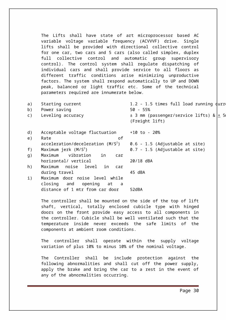
The Lifts shall have state of art microprocessor based AC variable voltage variable frequency (ACVVVF) drive. Single lifts shall be provided with directional collective control for one car, two cars and 5 cars (also called simplex, duplex full collective control and automatic group supervisory control). The control system shall regulate dispatching of individual cars and shall provide service to all floors as different traffic conditions arise minimizing unproductive factors. The system shall respond automatically to UP and DOWN peak, balanced or light traffic etc. Some of the technical parameters required are innumerate below.
a) Starting current 1.2 - 1.5 times full load running currentb) Power saving 50 - 55%c) Leveling accuracy ± 3 mm (passenger/service lifts) & + 5mm
(Freight lift)
d) Acceptable voltage fluctuation +10 to - 20%e) Rate of acceleration/deceleration (M/S2) 0.6 - 1.5 (Adjustable at site)f) Maximum jerk (M/S3) 0.7 - 1.5 (Adjustable at site)g) Maximum vibration in car horizontal/ vertical 20/18 dBAh) Maximum noise level in car during travel 45 dBAi) Maximum door noise level while closing and
opening at a distance of 1 mtr from car door 52dBA
The controller shall be mounted on the side of the top of lift shaft, vertical, totally enclosed cubicle type with hinged doors on the front provide easy access to all components in the controller. Cubicle shall be well ventilated such that the temperature inside never exceeds the safe limits of the components at ambient room conditions.
The controller shall operate within the supply voltage variation of plus 10% to minus 10% of the nominal voltage.
The Controller shall be include protection against the following abnormalities and shall cut off the power supply, apply the brake and bring the car to a rest in the event of any of the abnormalities occurring.
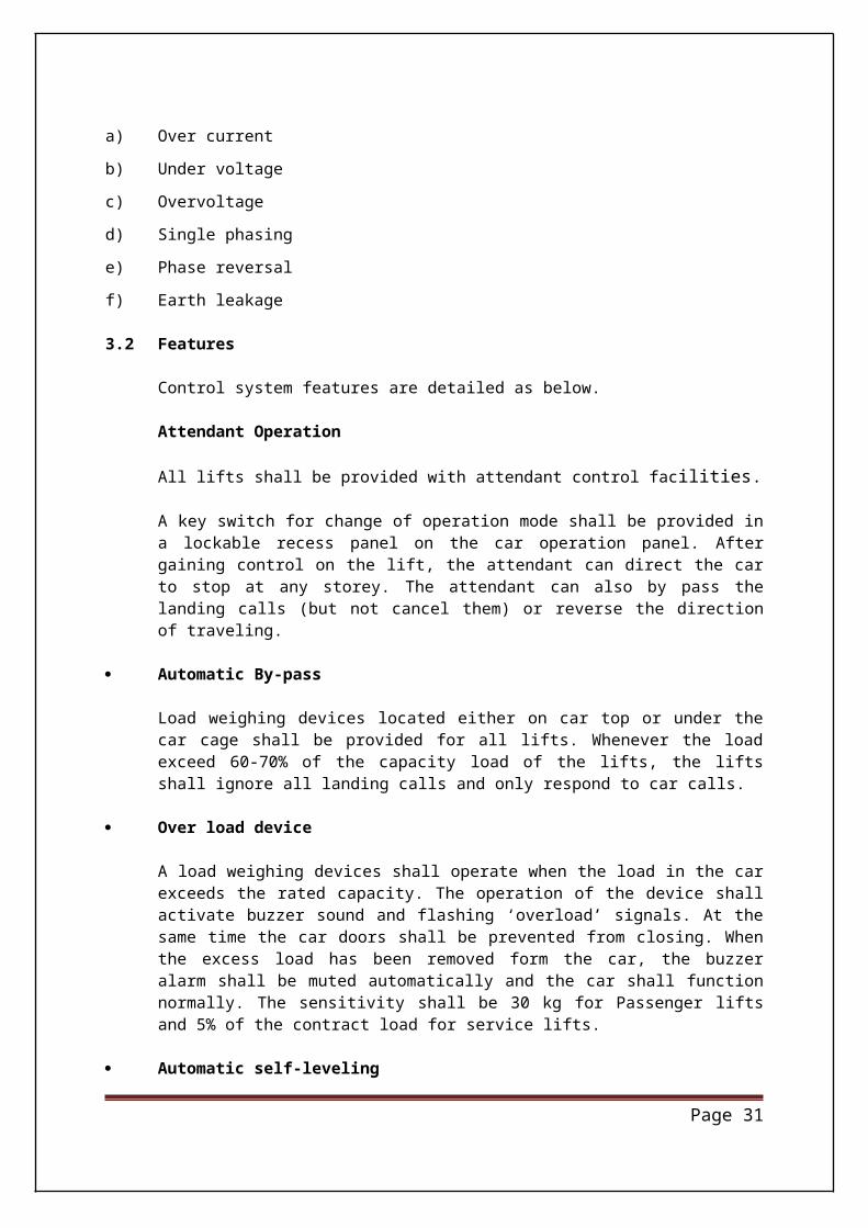
a) Over current
b) Under voltage
c) Overvoltage
d) Single phasing
e) Phase reversal
Page 21
f) Earth leakage
3.2 Features
Control system features are detailed as below.
Attendant Operation
All lifts shall be provided with attendant control facilities.
A key switch for change of operation mode shall be provided in a lockable recess panel on the car operation panel. After gaining control on the lift, the attendant can direct the car to stop at any storey. The attendant can also by pass the landing calls (but not cancel them) or reverse the direction of traveling.
Automatic By-pass
Load weighing devices located either on car top or under the car cage shall be provided for all lifts. Whenever the load exceed 60-70% of the capacity load of the lifts, the lifts shall ignore all landing calls and only respond to car calls.
Over load device
A load weighing devices shall operate when the load in the car exceeds the rated capacity. The operation of the device shall activate buzzer sound and flashing ‘overload’ signals. At the same time the car doors shall be prevented from closing. When the excess load has been removed form the car, the buzzer alarm shall be muted automatically and the car shall function normally. The sensitivity shall be 30 kg for Passenger lifts and 5% of the contract load for service lifts.
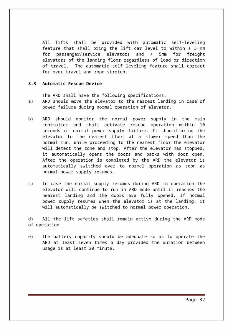
Automatic self-leveling
All lifts shall be provided with automatic self-leveling feature that shall bring the lift car level to within ± 3 mm for passenger/service elevators and + 5mm for freight elevators of the landing floor regardless of load or direction of travel. The automatic self leveling feature shall correct for over travel and rope stretch.
3.3 Automatic Rescue Device
The ARD shall have the following specifications. a) ARD should move the elevator to the nearest landing in case of power failure during normal
operation of elevator.
b) ARD should monitor the normal power supply in the main controller and shall activate rescue operation within 10 seconds of normal power supply failure. It should bring the elevator to the nearest floor at a slower speed than the normal run. While proceeding to the nearest floor the elevator will detect the zone and stop. After the elevator has stopped, it automatically opens the doors and parks with door open. After the operation is completed by the ARD the elevator is automatically switched over to normal operation as soon as
Page 22

normal power supply resumes.
c) In case the normal supply resumes during ARD in operation the elevator will continue to run in ARD mode until it reaches the nearest landing and the doors are fully opened. If normal power supply resumes when the elevator is at the landing, it will automatically be switched to normal power operation.
d) All the lift safeties shall remain active during the ARD mode of operation
e) The battery capacity should be adequate so as to operate the ARD at least seven times a day provided the duration between usage is at least 30 minute.
Page 23
TECHNICAL SPECIFICATIONSLIFT CAR, DOOR AND SAFETY DEVICES
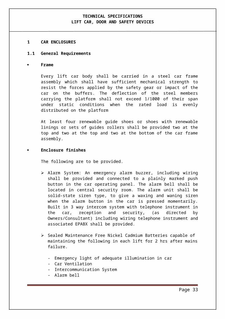
1 CAR ENCLOSURES
1.1 General Requirements
Frame
Every lift car body shall be carried in a steel car frame assembly which shall have sufficient mechanical strength to resist the forces applied by the safety gear or impact of the car on the buffers. The deflection of the steel members carrying the platform shall not exceed 1/1000 of their span under static conditions when the rated load is evenly distributed on the platform
At least four renewable guide shoes or shoes with renewable linings or sets of guides rollers shall be provided two at the top and two at the top and two at the bottom of the car frame assembly.
Enclosure finishes
The following are to be provided.
Alarm System: An emergency alarm buzzer, including wiring shall be provided and con-nected to a plainly marked push button in the car operating panel. The alarm bell shall be located in central security room. The alarm unit shall be solid-state siren type, to give a waxing and waning siren when the alarm button in the car is pressed momentarily. Built in 3 way intercom system with telephone instrument in the car, reception and se-curity, (as directed by Owners/Consultant) including wiring telephone instrument and associated EPABX shall be provided.
Sealed Maintenance Free Nickel Cadmium Batteries capable of maintaining the following in each lift for 2 hrs after mains failure.
- Emergency light of adequate illumination in car - Car Ventilation - Intercommunication System - Alarm bell
One no. 16 amp switch socket outlet to IP 54 and a permanent weatherproof type lumi -naries to IP54 (with lighting switch ) adequately protected shall be provided on the top of the lift car for maintenance
One no. 16 amp switch socket outlet to IP 54 at bottom of lift car for maintenance
1.2 Operation Panel
A full length car operating panel incorporating following control/indications shall be provided in each lift on the return panel
LED Illuminated touch push buttons of micro pressure type corresponding to the floors served
Door open and door close button
Page 24
TECHNICAL SPECIFICATIONSLIFT CAR, DOOR AND SAFETY DEVICES
Emergency stop button with Alarm Two position key operated switch for 'with attendant' and 'without attendant' operation. Ventilation fan ON/OFF switch with auto OFF when there is no call after 120 seconds (Two
Speed & concealed vents). Built in intercom of the hands free type as well as space for providing EPABX telephone in -
strument and 5 pair telephone trailing cable to communicate from car to Two Locations i.e. Operator’s Room (at remote location) & Security Guard Room and vice-versa.
Dynamic car direction display Car position indicator (digital) Audio/Visual overload warning indicator In order to have at least one device of communication functioning at all the times, as an al -
ternative arrangement, it is recommended that the provision of both i.e. telephone with minimum connections-one at the operator’s room and other at guard room and the emer-gency signal with re-chargeable batteries as source of supply be made in the lift cars.
The device used for emergency signals should incorporate a feature that gives a immediate feed back to the car passengers that the device has worked properly and the signal has been passed on to the intended agency.
Digital voice synthesizer (Optional) for announcing special messages with background music.
1.3 Landing fixture
The landing fixtures shall be recess mounted on a base junction box in the wall by the side or on top of landing doors as required.
Each landing fixtures shall consist of micro touch type landing call buttons with illuminated call acknowledge signal and illuminated digital type car position indicators on separate stainless steel face panels with hairline finish. Alternatives as available with bidders shall be indicated in tender for owners approval.
The following landing fixtures shall be provided for each lift.
a) Lowest floor Up call button Digital car position indicators Travel direction indicators “In use” indicator to signify the lift door is opened for delivery at a certain landing
b) All floors other than lowest and top most floor Button up and down call buttons Travel direction indicators Digital car position indicators with Gong (Optional) “In use” indicators to signify the lift door is opened for delivery at a certain landing Manual by pass key switch for lift landings.
c) The top most floor Down call button Travel direction indictors Digital car position indicators with Gong (Optional) “In use” indicators to signify the lift door is opened for delivery at a certain landing
Page 25
TECHNICAL SPECIFICATIONSLIFT CAR, DOOR AND SAFETY DEVICES
Manual by pass key switch for lift landings.
12 V 20 W tungsten halogen spotlights shall be supplied and installed on the underside of the hall lanterns. The spot lights on a particular floor shall be lit up to signify the arrival of the corresponding lifts. These spotlights shall be switched off after the corresponding lifts have left that particular floor. For passenger cars, the spotlights on the parking floor shall be turned off after a present period adjustable from 15 to 150 sec. Should a call from the parking floor be registered, spotlight of the assigned parking car shall be switched on again together with the opening of the landing doors to attend the call
2. CAR AND LANDING DOORS
2.1 General requirements
All car doors shall extend to the full height and width of landing opening unless otherwise specified and shall be operated with variable frequency door operator. A similar imperforate door shall be provided for every landing opening in the lift hoistway enclosure. The top track of the landing and car doors shall not obstruct the entrance to the lift cars. All car and landing doors shall have a fire resistance of not less than 1 hour.
In addition, all the car and landing doors shall meet the following general requirements.
a) Car door locking devices Every car door shall be provided with an electrical switch to prevent the lift car from being started or kept in motion unless the car door is closed. A mechanical locking device shall also be provided to prevent door opening from inside the car whilst the car is in motion.
b) Landing door locking devices Every landing door shall be provided with a mechanical locking device to prevent opening of the door from the landing side in normal cases unless the lift car is in that particular landing zone.
c) Projections and recesses Sliding car and landing doors shall be guided on door tracks and sills for the full travel of the doors. The distance between the cars and the landing sills shall not exceed 35 mm.
d) Door locking devices All doors locking devices, door switches and associated actuating rods, levers or contracts, shall be inaccessible from the landing or the car.
e) Protective devices Protective devices shall be fitted to the leading edges of both car door panels. It shall automatically initiate reopening of the door in the event of a passenger being struck (or about to be struck) by the door in crossing the entrance during the closing movement. The obstruction of either leading edge when closing shall actuate the protective device to function.
f) “Door open” alarm “Door open” alarm shall be provided in the car to initiate alarm and a continuous buzzer if a
Page 26
TECHNICAL SPECIFICATIONSLIFT CAR, DOOR AND SAFETY DEVICES
car or landing door has been mechanically kept open for a present period. The period shall be adjustable from 0-10 minute.
g) Emergency landing door unlocking devices and key Every landing door shall be provided with an emergency landing door unlocking device.
When operated by an authorized person with the aid of a key to fit the unlocking triangle, the landing door shall be unlocked irrespective of the position of the lift car for rescue pur-pose. When there is no “unlocking” action, the key shall only be able to stay in the locked position.
In the case of coupled car and landing doors, the landing doors shall be automatically closed by means of weight or springs when the car is outside the unlocking zone.
2.2 Door Hangers and Tracks
The car and the landing doors shall be provided with two point suspension sheave type hangers complete with tracks. Sheaves and rollers shall be steel with molded nylon collar and shall include shielded ball bearings. Tracks shall be of suitable steel section with smooth surface. The landing doors shall be complete with headers, sills, frames etc. as required.
2.3 Lift Door Protection
Multiple-Infra red door protection and mechanical shoes shall be provided for all lift to control door movement which shall cover the entire door opening effectively.
2.4 Protective Hand Rail in the Car (Optional as this will depend on interior design)
2.5 CABIN FAN
A noiseless pressure fan (two speed and concealed vent) shall be provided in the lift cabin.
3. HOIST ROPES
Hoist way material shall be non-flammable (02 hrs fire rated) except travelling cables which shall be flame resistant.
Lift Ropes – IS 14665 (Part 4 / Sec 8)-2001
Round strand steel wires ropes made from steel wire ropes having a tensile strength not less than 12.5 tonnes/cm2 and of good flexibility shall be used for lift. Lubrications between the strands shall be achieved by providing impregnated hemp core. The lift ropes shall conform to IS 14665-(Part-4-Sec. 8):2001 and the following factor of safety shall be adhered to. The minimum diameter of rope for cars and counter weight of passenger and goods lift shall be 8mm.
Page 27
TECHNICAL SPECIFICATIONSLIFT CAR, DOOR AND SAFETY DEVICES
Rope speed of Passenger & Passenger cum Goods Lifts (Service Lift) (m/s)
Factor of safeties
0.5 or less 8exceeding 0.5 to 1.0 8.6exceeding 1.0 to 2.0 10exceeding 2.0 to 3.5 11exceeding 3.5 12
Rope fastenings
The ends of lift ropes shall be properly secured to the car and counter weight hitch plates as the case may be with adjustable rope shackles having individual tapers babbit sockets, or any other suitable arrangement. Each lift rope shackle shall be fitted with a suitable shackle spring, seat washer, shackle nut & lock & shackle nut split pin.
Guards for Lift Ropes
Where lift ropes run round a sheave or sheaves on the car and/ or counterweight of geared/ gearless machine suitable guards shall be provided to prevent injury to maintenance personnel.
Number & Size of Ropes
The contractor must indicate the number and size of lift ropes and governor ropes proposed to be used, their origin, type, ultimate strength and factor of safety. The contractor should furnish certificate or ropes from the rope manufacturers issued by competent authority.
4. COUNTER WEIGHT
The counter weight for lift cars shall be in accordance with clause 6 of IS 14665 (Part 4-Sec-3) : 2001 and shall be designed to balance the weight of empty lift car plus approximately 50 percent of the rated load. It shall consist of cast sections firmly secured in relative movement by at least two numbers steel tie rods having lock nuts/split pins at each end and passing through each section and Housed in a rigid steel frame work. Cracked and broken sub weights shall not be accepted. Counter weight for passenger lifts should be able to accommodate approx 350 kg weight Interior finishes. In case interior finishes material exceeds this provision, then the elevator contractor shall adjust the Counter Weight accordingly, however this will be decided and intimated much before the delivery of the elevators.
Counter Weight Guards
Guards of wire metal / mesh shall be provided in the lift pit to a suitable height above the pit floor to eliminate the possibility of injuries to the maintenance personnel.
5. GUIDES / Guide RailsCar and counterweight guide shall be machined T section as per relevant Indian Standards IS-14665 of 2000 revised up to date. The guides shall be capable of withstanding forces resulting from the application of the car or counter weight safety devices The guide rails
Page 28
TECHNICAL SPECIFICATIONSLIFT CAR, DOOR AND SAFETY DEVICES
shall be minimum 16mm Tongued & Grooved type.
6. TRAILING CABLES
A single trailing cable for lighting control and signal circuit is permitted, if all the conductors of this trailing cables are insulated for maximum voltage running through any one conductor of this cable. The lengths of the cables shall be adequate to prevent any strain due to movement of the car. All cables shall be properly tagged by metallic / plastic tags for identification. Cable jacket should be suitable for immersion in water, salt water & oil etc.
Trailing cables shall run from a junction box on the top of the car to a junction box located in the shaft bear mid point of travel and from these junction boxes conductors shall be run to the various locations.
Trailing cables exceeding 30 meters in length shall run so that the strain on individual cable conductors will be reduced to a minimum and the cables are free from contact with the car counterweight, shaft walls or other equipment.
Trailing cables exceeding 30 meters in length shall have steel supporting fillers and shall be suspended directly by them without rubbing over other supports.
Cables less than 30 meters in length shall have no – metallic fillers and shall be suspended by looping cables around supports of porcelain spools type or equivalent.
5 percent of the total capacity subject to a minimum of 5 wires shall be available unutilised in the trailing cable everywhere suitable distributed between various functions.
7. SAFETY DEVICES
Safety devices shall be capable of operating only in the downward direction and stopping fuly loaded car, at the tripping speed of the over speed governor, even if the suspension devices break, by gripping the guides, and holding the car there. Governor sleeve in elevator pit shall be enclosed in a wire cage to a height of 2.40 mtr. All safety devises statutorily required by Lift Inspector, including but not restricted to the following shall be provided.
Terminal slow down switches
These shall be provided and installed to slow down the lift car when approaching the top and bottom landings. The slow down switches shall act independently from the normal car operating device.
Over travel limit switches
These shall be provided and installed to stop the car within the top and bottom clearance, independent of the normal car operating device. The bottom over travel limit switch shall become operative when the bottom of the car touches the buffer.
When the over travel limit switches are operative, it shall be impossible to operate the car until the car has been hand would to a position within the normal travel limits.
Page 29
TECHNICAL SPECIFICATIONSLIFT CAR, DOOR AND SAFETY DEVICES
Pit Switch
An emergency stop switch shall be located in the pit which when operated shall stop the car regardless of the position of hoist way.
Terminal Buffers
Suitable spring buffers mounted on RCC foundation blocks shall be provided in the pit in compliance with ANSI/ASME/CENEN-81 /JIS codes for stopping the car in case of mal-operation. Dowels for the purpose shall be left while casting the pit floor alternatively floor reinforcement could be exposed by chipping for welding additional reinforcement for Dowels. However clearance from underside of the car resting on a fully compressed buffer shall not be less than 1.20 mtr. Buffers shall be designed for a design speed + 15%. Oil buffers shall be provided for the passenger elevators for speed of more than 1.75 mps and spring buffers for lower speed.
Interlocking
Adequate interlocking is to be provided so that the car shall not move if the landing doors are even partially open and also the lift is overloaded.
Over speed governor
Over speed governor shall be of centrifugal type and shall operate the safety gear at a speed at least equal to 115% of the rate speed and less than the over speed governors shall be driven by flexible wire ropes with the following requirements.
- The breaking load of ropes shall be related to the force required to operate the safety gear by the safety factor of at least 8
- The nominal rope diameter shall be at least 7 mm- The radio between the pitch diameter of the over speed governor pulley and the nomi -
nal rope diameter shall be at least 30
The over speed governors shall be sealed after setting the tripping speed.
The breaking or slackening of the governor rope shall cause the motor to stop by an electric safety device.
Alarm bells
A Concealed 200 mm diameter alarm bell shall be installed in the main security area. The alarm bell shall sound when the alarm bell button in the car operating panel is pressed. The bell shall mute when the pressure on the alarm bell button is released.
Emergency Stop Switches
An emergency stop for use by maintenance personal shall be provided in each lift car.
Page 30
TECHNICAL SPECIFICATIONSLIFT CAR, DOOR AND SAFETY DEVICES
Page 31
TECHNICAL SPECIFICATIONSLIFT CAR, DOOR AND SAFETY DEVICES
8 FIREMAN SWITCH
Each Lift shall have a Fireman switch with glass front for access by the Firemen. The operation of this switch shall cancel all calls to this lift and shall stop at the next nearest landing if traveling upwards. The doors shall not open at this landing and the lift shall return to the ground floor. In case the lift is traveling downwards when the fireman's switch is operated it shall go straight to the ground floor bypassing all calls enroute. The emergency stop button inside the car shall be rendered inoperative.
The fireman’s switch shall be located adjacent to the lift opening at the terminal floor and shall be at a height of approximately 2 m above the floor level. For easy identification of firemen’s lift which confirm to the local authorities requirements, a red and white diagonal striped backing shall be provided behind the glass of the firemen’s switch.
A permanent notice of prominent size indicating the floors served shall be provided and displayed adjacent to the firemen’s lift at the terminal floor. The notice shall be made of laminated plastic sheet or other approved materials with red letters on white background. Details of the notice shall be submitted to the Engineer-in-Charge for approval prior to fabrication.
9. CONTROL OF NOISE AND VIBRATION
9.1 General
The whole of the lift assembly, including the opening and closing of the car and landing doors shall be quiet in operation and shall be free of rattling or squeaking noises. Lift doors operation shall be smooth to avoid the transmission of impact noise to the surrounding structure.
Noise level resulting from the operation of the lifts, including direct sound transmission, breakout noise and re-radiation of structure borne noise, shall not exceed the specified noise criteria of the adjacent spaces. Vibration resulting from operation of lifts of escalators shall not be perceptible in any occupied areas.
9.2 Car construction
All elements of the lift car construction shall be sufficiently rigid to avoid generation of noise by panel excitation as a result of movement. The total noise level in a moving lift car shall not exceed 45 dBA with the ventilation system operating.
9.3 Machinery
The gearless traction machine and compact PM motor are installed within the hoist way and the slim control panel is located on the shaft side wall. Provision shall be made for the control vibration isolation measures employed to ensure that structure borne noise resulting from the operation of the lift machinery is not audible in any occupied area.
Lift machinery noise levels under normal operating conditions shall not exceed 70 dBA at 1
Page 32
TECHNICAL SPECIFICATIONSLIFT CAR, DOOR AND SAFETY DEVICES
m from the equipment in free field.
9.4 Arrival chimes
Noise from arrival chimes shall not exceed 60 dBA.
The above levels shall be measured at 3 m from the arrival chimes using a noise meter set to ‘fast’ response. Chimes with adjustable loudness shall be provided.
10. FIRE SAFETY REQUIREMENTS
General requirements of lifts shall be as follows :
10.1 Landing doors in lift enclosures shall have a fire resistance of not less than one hour.
10.2 Lift car door shall have a fire resistance rating of one hour.
10.3 Grounding switch (es), at ground floor level, shall be provided on all the lifts to enable the fire services to ground the lifts
Page 33
ASSOCIATED ELECTRICAL WORKS
1.1 Scope
Based on power requirements of lifts furnished by the lift contractor, power supply for the lifts machines, terminating in a Switchboard located at a desired location, shall be provided by Engineer-in-charge. The earth bar provided on this Switchboards shall be connected to the building earthing system also by Engineer-in-charge. All cabling / wiring/loop earthing beyond this Switchboard for interconnection with the lift controllers / motors/ indicators / push buttons / safety devices etc. shall be provided by the lift contractor and its cost shall be deemed to be included in the quoted rates.
1.2 Cabling
Cabling between switchboard and the controller /lift motor shall be with XLPE insulated HR PVC sheathed 1100 volt grade aluminum conductor armoured cables conforming to IS 7098 or PVC insulated, PVC sheathed, 1100 volt grade al conductor armoured cables conforming to IS 1554. Cables shall be terminated in glands fitted with armour clamps the gland body shall be provide with an internal conical sating to receive the armour clamping cone and clamping nuts which shall secure the armour wires. A PVC shroud shall be fitted to cover the gland body and exposed armour wires
Trailing cables for the lifts shall be EPR insulated stranded copper conductor flexible cables conforming to IS 9968
Control cabling shall be with multi core stranded copper conductor PVC insulated and sheathed 1100 volt grade cables conforming to IS 8130. Minimum size of the cable shall be 2.5 sq mm.
Where cables pass through walls or floor slabs, pieces of GI sleeves shall be provided for cast into the wall / floor and cable shall be drawn therein. Annular space around the cable in the sleeve shall be sealed with fire proof sealant supplied by Engineer-in-charge.
1.3 Wiring
All wiring shall be carried out with FRLS PVC insulated 1100 volt grade stranded copper conductor wires conforming to IS 694 drawn in MS rigid / flexible conduiting system and / or MS raceways. Minimum 2.5 sq mm size wires shall be used. Wires shall be cut only at terminations. Intermediate jointing shall not be permitted. Drawing, cutting and terminating of the wires shall comply with the relevant Indian standard specifications and shall be carried out in the most workman like manner as per standard practice. All normal care like cutting the insulation with a pencil edge, taking care not to cut the strands and proper tightening of terminal connector screws to avoid loose connection or breaking of conductors etc. shall be taken.
Heavy gauge black enameled screw type ISI embossed MS conduits with superior quality accessories approved by Engineer-in-Charge shall be used in the work. Conduits could either be recessed in floors / walls or fixed on surface with saddles and clamps. Final connections
Page 34
to vibrating the equipment shall be made with metal flexible conduits. Entire work shall be carried out in work man like manner as per standard practice
1.4 Earthing
Metal enclosures of all electrical equipment and devices including frames of motors, controllers, switchgear, conduits and raceways etc. shall be properly earthed so as to form an equiv.-potential zone. Loop earthing of vibrating equipment shall be done with flexible copper earthling braid or flexible cables. The lift motor frame shall be connected to the building earthling system termination at the switchboard by duplicate loop earthling conductors of appropriate size.
2. ASSOCIATED CIVIL & STRUCTURAL ITEMS
All civil and structural items of work associated with erection and operation of lifts shall be provided by the Contractor at his cost including (but not restricted to) the following.
Hook for lifting lift equipments in the top of shaft. Temporary scaffoldings and safety barricades during lift installation in and around lift Lift
wells Sill angels Bearing plates Buffer supports Checqured plates Fascia plates Ladders in pits (MS) Safety railing on car top Separator /stretcher beams if required . Dowels for terminal buffers in pit floor during casting.
The Contractor shall ensure erection and fixing of steel work in such a manner that no RCC wall or any other structural member is damaged.
Page 35
MAINTENANCE SERVICES
1. SCOPE
The Contractor shall provide Free Comprehensive Maintenance service for a period on one years from the date of handing over of the lift to Engineer-in-Charge. After expiry of this free comprehensive maintenance period, Bank reserve right to enter into annual maintenance contract with the contractor as per rates finalized in the contract
The maintenance services rendered by the contractor (free maintenance for one years after handing over and as per AMC if entered into for subsequent years) shall include routine and preventive maintenance as also breakdown maintenance if and when required. Maintenance services shall be provided with 24 hour emergency call out service.
2. ROUTINE AND PREVENTIVE MAINTENANCE
Program of routine and preventive maintenance during the free (1 year) maintenance period as also during the tenure of annual maintenance contract shall comply with minimum requirements as below.
2.1 Fortnightly
To check all bearing oils, oil rings, oil chains, etc. All machines should be carefully checked and repaired for abnormal temperature rise.
To check and repair all relays and contacts as wells as their movements and repair as necessary
To clean traction machines, relays panels, control panel, starter panels, selectors, governors, car top, car gates, sills and pits
To check brake action and adjust if necessary To check and repair movement of door switches, gate switches and emergency stop
switches To check and repair indicator lamps and indicator To check and repair annunciator lights, buzzer and car lights To check and adjust leveling differences, brake slippage, acceleration, deceleration
and riding comfort. To check and repair movements of car control buttons, switches and the like. To check and repair operat5ion of weighting devices.
2.2 Monthly
To turn grease cups for speed governors and compensating pulleys To check and oil selectors To top up rail lubricators To clean ropes oil if necessary To clean PM motor and inspect controller box etc. To oil electric brake pins To oil all pins of door operation and door opening mechanisms To clean hoist way, beams slow down cams, outside cages, rails and counterweight
rails
Page 36
To clean, oil and adjust door closer and levers To clean main sheave, secondary sheaves and rope sheaves on car top and counter-
weigh top To clean and repair brake wheels and shoes To oil compensating rope tensioning pulleys.
2.3 Every Two months
To clean and oil door hangers, door rails, interior of hanger case. If necessary adjust acentric rollers, car door hangers, door connecting ropes and chains
To check and repair door shoe To clean and oil safety fears To clean and oil car and counterweight guide shoes. Adjust if necessary To clean and oil interior of terminal limit switches and position switches. Check rub-
ber rollers of terminal limit switches. To check oil clean and repair interior of door switches, gate switches. Replace worn
parts if necessary To check and repair flexible cable To check and repair movement of limit switches To clean and oil interior of car control switches. To clean and check push buttons of care control panels To check, clean and repair the sleeve and plungers of the electromagnetic brakes.
2.4 Every three months
To check and repair the operation of terminal limit switches and final limit switches. To check and repair the governor switches. To clean the brush holders and commentators of the door motors. To check and repair the traction ropes for broken wire, wear elongation and even
tension. Adjust if necessary. To remove the dust inside the traction machines and controls panels using electric
blower To clean and repair the indicator lamps To check the voltage of rectifiers and thyristors
2.5 Half yearly
To check and repair the operation of safety gears To check oil for oil buffers To check and clean the hall buttons and contacts To check and repair the compensating chains or ropes To check and oil the bearing of door motors To grease the secondary sheaves, car top sheaves and counterweights. To check the wear of guide shoes of cars and counterweights
Page 37
2.6 Annual
To clean the wire connection box of every landing and car cages. Tighten all screws and check the conditions of cables at conduit inlets and outlets
To check and tighten screws of control panels, starters panels and relay panels To remove the dust inside the landing indicator switches by electric blower To test all safety devices To dismantle, clean and adjust the electro magnetic brake of gearless machines To charge motor oil To check and tighten screws and foundation bolts of traction machine, secondary
sheaves, exterior of lift frame, guide rail, guide rail clamps and bracket etc. To test the overcurrent relays To provide all labour, materials, tools and transport to carry out annual inspection
and load test according to the requirement of the employer
All the scheduled maintenance services described above shall be properly programmed and agreed with the Engineer-in-charge in order not to affect operation of the lift systems
3. BREAK DOWN MAINTENANCE
The Contractor shall also undertake to provide a comprehensive breakdown service whereby qualified technicians shall attend to each breakdown as soon as practicable after a breakdown is reported and carry out immediate remedial work at a reasonable speed according to the nature of the breakdown. Any faulty equipment or components shall be quickly replaced.
In circumstance such that the Contractor fails to attend the breakdown within four normal working hours after notification of the breakdown and where remedial work is interrupted during normal working hours for purposes other than obtaining replacement parts, the employer reserves the right to order such action as may be necessary to expedite completion of remedial work which shall be at the Contractors expense without abrogation of the Contractors responsibilities
4. GENERAL
The Contractor shall keep sufficient spare parts during the maintenance period to ensure that replacement work for defect can be carried out immediately
A competent engineer shall be provided to investigate the fundamental cause of a fault temporary quick fix solution will not be accepted.
The employer shall at his discretion, take action to recover all losses incurred rising from the failure of the contract to perform the duties either wholly or in part as detailed in this section
Page 38
TESTING OF LIFT INSTALLATION
1.0 TESTS AT SITE:
1.1 a) Leveling Test:
Accuracy of the floor levelling shall be tested with the lift empty, fully loaded.The lift shall be run to each floor while travelling both in upward and downward directions and the actual distance of car floor above/ below landing floor shall be measured. In each case there shall not be any appreciable difference in these measurements for levelling at the floors when the car is empty and when it is fully loaded. The tolerances for levelling shall be as + 5mm accuracy.
b) Safety Gear Test:
Instantaneous safety gear controlled by a governor, should be tested with contract load and a contract speed, governor being operated by hand. Two tests should be made, however, with wedge clamps or flexible clamp safeties, one with contract load in the car and the other with 68 kg (equivalent to one person) in the car. The stopping distance obtained should be compared with specified figures and the guides, car platform, and safety gear should be carefully examined afterwards for signs of permanent distortion.
Counterweight safety gear should be tripped by the counterweight governor and the stopping distance noted. In this case, however the governor tripping speed should exceed that of the car safety governor but by not more than 10 percent.
During the safety gear test, car speed (from the governor or the main sheave) should be determined at the instant or tripping speed with that stated in I.S. The governor jaws and rope should be examined for any undue wear.
c) Contract Speed:
This should be measured with contract load in the car, with half load with no load, and should not vary from the contract speed by more than 10 percent. The convenient method is by counting the number of revolutions, made by the sheave or drum in a known time. Chalk mark on the sheave or drum and a stop switch will facilitate timing but care must be exercised to ensure that no acceleration or retardation periods are included. If the roping is 2 to 1 the sheave speed is twice the car speed. Alternatively, the speed can be measured by a tachometer applied directly to shaft immediately below the sheave.
d) Lift Balance:
After the above test, some of the weight shall be removed until the remaining weights represent the figures specified by the tenderer. With this condition car at half way travel the effort required to move the lift car in either direction with the help of winding wheel shall be as nearly as can be judge by the same.
Page 39
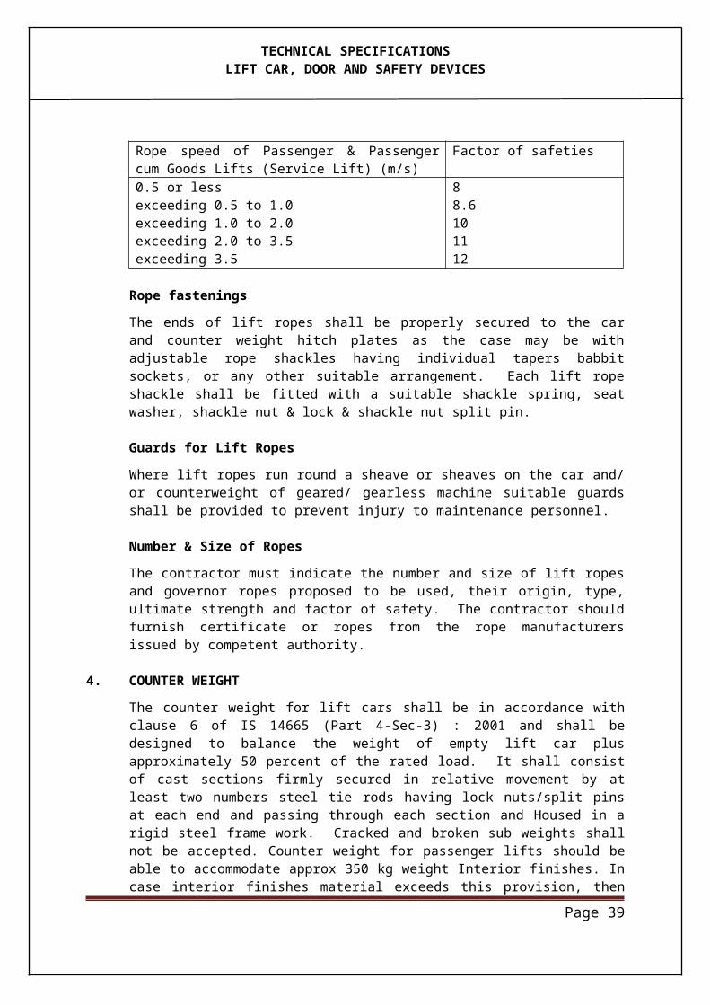
e) Car and landing doors interlocks:
The lift shall not move with any door open. The car door relay contact and the retiring release cam must be tested. The working of the door operation and the safety edges and light equipment if any provided shall also be examined.
f) Controllers:
The operation of the contactors and interlocks shall be examined and it shall be ascertained whether all requirements laid down in the specifications have been met.
g) Normal Terminal Stopping Switches:
This shall be tested by letting the car run to each terminal landing in turn, first with no load and then with contract load and by taking measurements, top and bottom over travels can be ascertained.
h) Final Terminal Stopping Switches:
The normal terminal stopping switches shall be disconnected for this test. It shall be ensured that these switches operate before the buffers are engaged.
i) Insulation Resistance:
This shall be measured (after removing the electronic PCB’s and their connection) between power and control lines and earth and shall not be less than 5 mega-ohms when measured with D.C. voltage of 500 volts. The test shall be carried out with contactors so connected together as to ensure that all parts of every circuit are simultaneously tested.
j) Earthing:
All conduits, switches, casing and similar metal work shall have earthing continuity.
k) Ropes:
The size, number construction and fastenings of the ropes should be carefully examined and recorded.
l) Buffers:
The car should be run on to its buffers at contract speed and with contract load in the car to test whether there is any permanent distortion of the car or buffers. The counterweight buffers should be tested similarly.
Page 40
1.2 Tests at Manufacturer’s Works:
a) High Voltage Test:
The dielectric or electric apparatus (excluding motors, generators and instruments which are tested in accordance with the appropriate Indian Standards wherever they exist) shall be capable of withstanding a test voltage of ten times the working voltage with a maximum of 2000 Volts when applied.
i) between the live parts and case of frame with all circuits completed.ii) between main terminals or equivalent parts with all circuits open, andiii) between the lift parts of independent circuits.
Note : Owing to the impracticability of applying tests (ii), (iii) mentioned above on controllers and similar apparatus after controller wiring has been completed, these tests may be made at convenient stages of manufacturer.
b) i) Method of Applying High Voltage:
The test shall be made with alternating voltage of any convenient frequency, preferably between 49 to 60 cycles per second. The test voltage shall be approximately sine-wave form and during the application of voltage with peak value, as would be determined by spark gap by occillograph or by any other approved method shall not be more than 1.45 times the rms value. The rms values of the applied voltage shall be measured by means of a volt meter used with a suitably calibrated potential transformer or by means of voltmeter used in connection with a special calibrated voltmeter winding or testing transformer by any other suitable voltmeter connected to the output side of the testing transformer.
ii) Duration of High Voltage Test:
The test shall be commenced at a voltage of about one third of the test voltage which shall be increased to the full test voltage as rapidly as is consistent with the value being indicated by the measuring instrument. The full test voltage shall be maintained for one minute. At the end of this period, the test voltage shall be rapidly diminished to one third of its full value before switching off.
The oil buffers are examined after the above tests have been made to determine if there has been any oil leakage or distortion and to ensure that the buffers return to their normal positions.
Page 41
c) Buffer Test:
A copy of the test report shall be intimated after testing at works.
1.3 Performance Test:
This test if meant for passengers lifts and is conducted to watch the performance of lift installation in terms of passenger handling capacity and waiting interval as obtained at site vis-a-vis design, data and conducted as below :
i) Waiting interval : (T)- This can be worked out by taking the average of several round trip times as observed physically and then dividing it by the number of lifts in that bank.
ii) Handling capacity H = 300 x Q x 100 T x P
Where
H = Handling capacity as the percentage of the peak population handled during 5 minutes.
P = Total population to be handled during peak morning/ evening period. (It is related to the area for which particular bank of lifts serves).
Q = Average number of passenger carried in a car.T = Waiting interval.
iii) Service Temperature Test :
A continuous run of one hour should be made with number of starts and stops to reproduce as nearly as practical the anticipate duty in service. (The standard duty cycle is for 90 to 180 start per hour). It is very difficult in practice to carry out this test with alternate starts at full load and no load and it is necessary therefore to simulate these cycles. A suitable test for all motors except squirrel cage motors is to run the car up from the bottom landing with contract load and stop at each floor. From the top floor a non stop run is made to the lowest floor and the upward journey with stop is then repeated. The time intervals between stops and starts at the floors should be uniform and such as to give about 180 starts in one hour. At the end of this run the temperatures of the armatures and fields of the motor and generator are recorded. The temperature rise should, be with in prescribed limit.
Page 42
TECHNICAL SPECIFICATIONS
CHECK LIST FOR JOINT INSPECTION OF LIFTS BY OWNER & FIRM'S REPRESENTATIVES REF. SECTION IV-TESTING OF LIFT INSTALLATIONS
1. Place of Inspection
2. Date of Inspection
3. Name of the Firm
4. Verify visually particulars as per agreement description andcompleteness of work to be executed as per contract.
5. Verify lay-out as per drawing and record discrepancies if any
6. Whether a plate with word LIFT and instruction to be dis-played /provided on each landing and in lift car.
LIFT WITH EQUIPMENT
(a) Depth of pit and whether ladder provided if required.(b) Arrangement for lighting in the pit.(c) Arrangement for lighting in the lift shaft.(d) Whether adequate tie rods provided for counter weights.(e) Whether all wiring has been in conduit pipes / troughs
properly fixed and earthed.(f) Guard for counter weights in the pit.(g) Provision of check nuts and split pins in rope fastenings
and terminations.(h) Whether rope tension equal for all ropes.(i) Whether buffers symmetrically positioned.(j) Top car clearance.(k) Bottom car clearance.(I) Top counter weight clearance(m) Bottom car run by.(n) Bottom counter weight run by.(0) Any other
7. Machine room check provision for:(i) Arrangement for hand lamp with flexible cord,(ii) A plug and socket.(iii) Adequate ventilation(iv) A danger plate on door(v) Trap door(vi) Main switch(vii) Circuit diagram on wall(viii) Any other
Page 43
8. EarthingWhether machine body controller, car frame, limit switches, and conduits properly earthed & check earthing continuity.
9. Machine and controller(i) Oil leakage if any(ii) Abnormal temp rise of oil, bearing and motor(iii) Abnormal noise or vibrations(iv) Whether UP and DOWN (direction arrows on motor or
fly wheel marked) (v) Whether rubber pads provided under machine and its
bed plates(vi) Whether control circuits have independent fuses (vii) Whether protection against breakage of rope or taps
for rope selector provided (viii) Whether cable ferrules marked (ix) Gap between the car and landing sill (x) Any other
10. Operation(i) Operation of all floor buttons from with- in the car
in up and down direction on both attendent and auto control.
(ii) Operation of car by calls given from landing buttons in up and down direction on both attendent and auto control.
(iii) Operation of door close and door open buttons (iv) Emergency alarm (v) Emergency stop (vi) Light and fan (vii) Emergency key opening (viii) Emergency light(ix) Operation on type of control stipulated in contract(x) Operation of car top safety switches to make the lift
inoperative from within the car and speed of opera-tion.
(xi) Door locking as checked from each floor (xii) Any abnormal noise vibration jerk interval and
stopping(xiii) Sideway play if any in the car. (xiv) Working of position and direction indicators in car
and at each landing. (xv) Functioning of sensitive reopening arrangements on
moving edge of doors.
Page 44
(xvi) Smooth sliding movement of car and landing doors,(xvii) Whether car is stopped in between the floor and
whether the doors can be opened manually from in-side.
xviii) Opening of landing or car door when lift is in operation to see that the movement of lift stops,
(xix) Operation of fireman switch.(xx) Check for brake release device and hand winding
provisions,
11. Safety Devices(i) Functioning of protection for single phasing and phase
reversal.(ii) Function of protection for automatic power cut off de
vice before the car and counterweight load on buffers.
(iii) Function of over load relays.(iv) Operation of safety gear and also see for undue
deformation of guiderails and stopping distance.(v) Check operation of safety switches.(vi) Operation of upper limit switch & positions(vii) Operation of lower limit switch and position (viii) Operation of electrical protection against opening of
emergency door.ix) Any other.
13 Checking of rope slip after 3 complete trips by putting a reference mark on the sheave and rope 60mm/12mm, 60mm/20mm.
14 Test to see that the lift does not start in upward direction on no load and down direction on full load and on single phasing
15 Check application of brake on full load in down direction at full speed by switching off the power supply and for over heating.
16 Load Test: Lift No.---------------------No Load Full LoadUP Down UP Down
Starting current :AC (Amp) Running current :AC (Amp) Travel (Meters) Speed: Meter/Sec
Page 45
17. Any other test(i) Size of the lift well(ii) Internal depth of car platform(iii) Size of the car door(iv) Rope protection against breakage have been carried
out and test results are found (v) Insulation resistance test & high voltage test have also
been tested. I.R. is found____________________M ohm (Requirement0.5 M ohm minimum) and HV test with stood/ not with stood
Page 46
PROVISION FOR THE DISABLED AND HANDICAPPED
1 All the Passenger Elevator shall be provided with following features:
a) Elevator control buttons at locations and height specified in IS 15330 - 2003
b) Hall call buttons at locations and height specified in IS 15330 - 2003
c) Hand rails shall be provided on the side walls of the Elevator at height & locations specified in IS:15330 - 2003. An international symbol of access of the disabled shall be permanently and conspicuously displayed at each and every Elevator landing next to the Elevator entrance (to be provided by signage contractor ). Braille notations indicating the floor levels shall be incorporated next to each button at the handicap COP and handicap hall call buttons.
d) A digital voice system for announcing the car position, opening/closing of doors, direction of travel and messages shall be provided as per IS:15330 - 2003
e) A laminated safety glass type mirror of at least half of the size shall be installed on rear panel at appropriate position as per IS : 15330 - 2003
Page 47
Annexure-I
TENDER DOCUMENT FOR SUPPLY, INSTALLATION, TESTING & COMMISSIONING OF LIFTS
TECHNICAL PARAMETERSNote : - Tenderers to give item wise confirmation/comment against each parameter. Deviations if any shall be clearly brought out in this Performa. Tenderers shall fill in the Performa and enclose it along with the tender.
B Decription Specific Requirements Confirmation by Tenderers1 Type of LIFTS Passenger Elevator2 Number of Lifts 1 no
3 Capacity 8 passenger (1020 kg) 4 Speed 1 mps5 Number of Landings 05 (Stlit floor + 4th floor)6 Number of openings 05 on the same side7 Travel 14.85 Mtrs ( Slit to Ground Floor-
2.45 Mtr, Ground to First Floor- 3.1 Mtr, First to 2nd floor 3.1 Mtr, 2nd to 3rd floor – 3.1 Mtr & 3rd to 4th floor -3.1 Mtr)
8 Power Supply 415 Volts (+/-10%) 3 phase, 50 cycles A.C)
9 Drive VVVF ( Variable Voltage Variable Frequency)
Control System Microprocessor Based Simplex full Collective Control with / without attendant
11 Lift Well size 1800mm X1900mm ( Width X Depth)
12 Car Size 1300mm X 1100mm ( Width X Depth) Approx
13 Car Enclosure Car and the panels shall be SS Hairline Finish
14 Car ceiling Shall be S/S hairline finish 15 Car floor 5 mm thick Aluminuim chequred
plate
16 Clear opening 1000mm X 2000mm ( Width X Height)
17 Electrical Light & fan LED lights/ 300mm with grill18 Car & Landing Entrance Auto Operation19 Indicators ( Car & Landing) Digital Position & Direction indicator
in Stainless Steel fixtures20 Special Features a) Battery Operated Alarm
b) Bell and Emergency Light
Page 48
c) Call Registers Type Micr Push Button
d) Phase Failuree) Fan & Light on / off switchf) Infrared Screeng) Fireman Switchh) ARD with indicator in COPi) Emergency light on COPj) Press and speak buttonk) Pit ladderl) Hand rail rear sidem) Load weight device in COPn) Speed Gov
21 Pit depth 1650 mm from Stilt floor
22 Overhead height 4700 mm23 Machine room size 4300mm(L) 3300mm(W)X3000mm
clear Height
Page 49
FINANCIAL BID
TENDER FOR SUPPLY, INSTALLATION, TESTING & COMMISSIONING OF LIFTS
BILL OF QUANTITIESSl No. Item Qty Unit Rate
(IN FIGS &
WORDS) (
Amount
Supply Installation
SUBHEAD - I : ELEVATORS
1.0 Design, manufacture, supply, installation, testing, commissioning, approvals and handing over in satisfactory working condition of lifts including the cost of providing free comprehensive maintenance for one years after handing over complete as per specifications and as required and as below.Lift with Machine Room
1.1 Passenger Lifts with 8 Pass/544 kg capacity,
1 mps speed, ACVVVF control, Simplex full collective Control with / without attendant
a) 05 stops (Stilt floor + 4th Floor) all on same side, travel 14.85 Mtrs approx 1 No.
TOTAL SUB-HEAD I carried over to Summary Rs
SUB HEAD - II : AMC
1.0 Projected charges for comprehensive (including the cost of spares & consumables etc.) Annual Maintenance Contact (AMC) fixed for One years after expiry of the initial Free Maintenance Period of 12 months.
Note: a). The amount of AMC will be taken into account
while evaluating the overall bid amount.
b) The rates to be quoted including all taxes i.e Service Tax, VAT, Excise duty etc.
Page 50
TOTAL SUB-HEAD II carried over to Summary Rs -
Page 51
TENDER DOCUMENT FOR SUPPLY, INSTALLATION, TESTING & COMMISSIONING OF LIFTS
BILL OF QUANTITIES
SUMMARY OF COSTS
Sub Head Description Value RsSupply Installation
I Elevators
II AMC
TOTAL VALUE
Rupees (in words) ………….………………………………………………………………………………… ……………………………………………………………………..............……........................................................................................................…………………..........................................................................................................................................….Only
Signature of Tenderer
Note :
1. Bidders to quote strictly as per the BOQ enclosed herewith in tender document
2. Complete tender document with all technical details only filled in the format provided in the tender shall be returned with just as annexure as terms / conditions if any required.
3. Failure to comply with above shall lead to disqualification of bidders.
Page 52
Annexure-AContractor Pre-qualification
1 COMPANY NAME
2 CONTACT PERSON
3 CONTACT No
4 Email
S No Criteria Details by Contractor
1 Man Power Strength (Nos) a) Project Manager b) Engineers c) Supervisors d) Foreman e) Skilled Labour
f) Unskilled / Semi Skilled La-bour
2 Company Turnover (in Cr) for the last 4 years
3 Value of Jobs in Hand (in Cr)
4 Value of Jobs executed in Last 4 years
Year 2013 -14 Year 2012 - 13 Year 2011 - 12 Year 2010 - 11
5Existing infrastructure in Delhi NCR (Company should have service centre in Delhi)
6 BG Limits Total Unexpired 7 Whether any arbitration pro-
Page 53
ceedings on for any pending works
If yes give detail 8 Client List Real Estate/ commercial Pvt Sector Govt. Sector
9List of Major Projects ex-ecuted in Last 2-3 years and Contract Value
Page 54