Embed Size (px)
Citation preview
Rotating Shadowband Pyranometers
Rotating Shadow Band Monitor at Toyah, TX
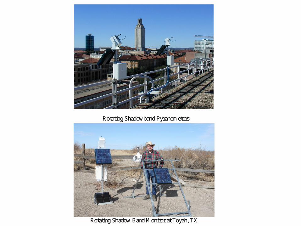
Computing Incident Solar Power on a Panel Surface To compute the incident solar power on a panel surface, we assume that the panel captures all of the diffuse horizontal (DH) power, plus the fraction of (GH – DH) that is perpendicular to the panel surface.
)cos()cos(
)(incidentzenith
sunincident
DHGHDHP
W/m2. (10)
The above value, in W/m2, is then multiplied by the panel surface area to yield total incident solar power incidentP . Multiplying by panel efficiency yields maximum expected electrical
power output.
tiltpanel
Line perpendicular to horizontal plane
tiltpanel
Horizontal plane
Figure 6. Panel Tilt Angle
Line perpendicular to panel surface
Edge of panel
zyxsun aaaa ˆcosˆsinsinˆcossinˆ zenithsun
azimuthsun
zenithsun
azimuthsun
zenithsun .
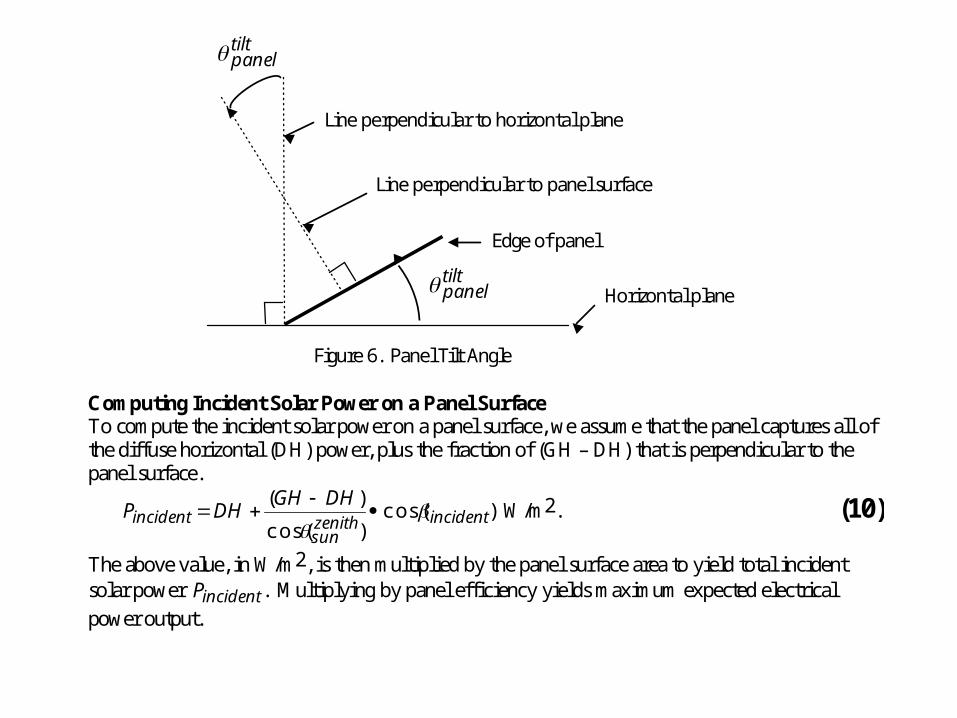
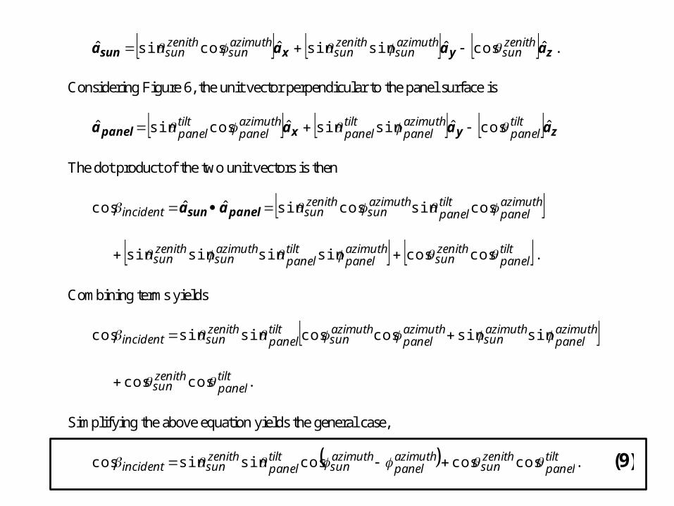
Considering Figure 6, the unit vector perpendicular to the panel surface is
zyxpanel aaaa ˆcosˆsinsinˆcossinˆ tiltpanel
azimuthpanel
tiltpanel
azimuthpanel
tiltpanel
The dot product of the two unit vectors is then
azimuthpanel
tiltpanel
azimuthsun
zenithsunincident cossincossinˆˆcos panelsun aa
azimuthpanel
tiltpanel
azimuthsun
zenithsun sinsinsinsin tilt
panelzenithsun coscos .
Combining terms yields
azimuthpanel
azimuthsun
azimuthpanel
azimuthsun
tiltpanel
zenithsunincident sinsincoscossinsincos
tiltpanel
zenithsun coscos .
Simplifying the above equation yields the general case,
tiltpanel
zenithsun
azimuthpanel
azimuthsun
tiltpanel
zenithsunincident coscoscossinsincos . (9)
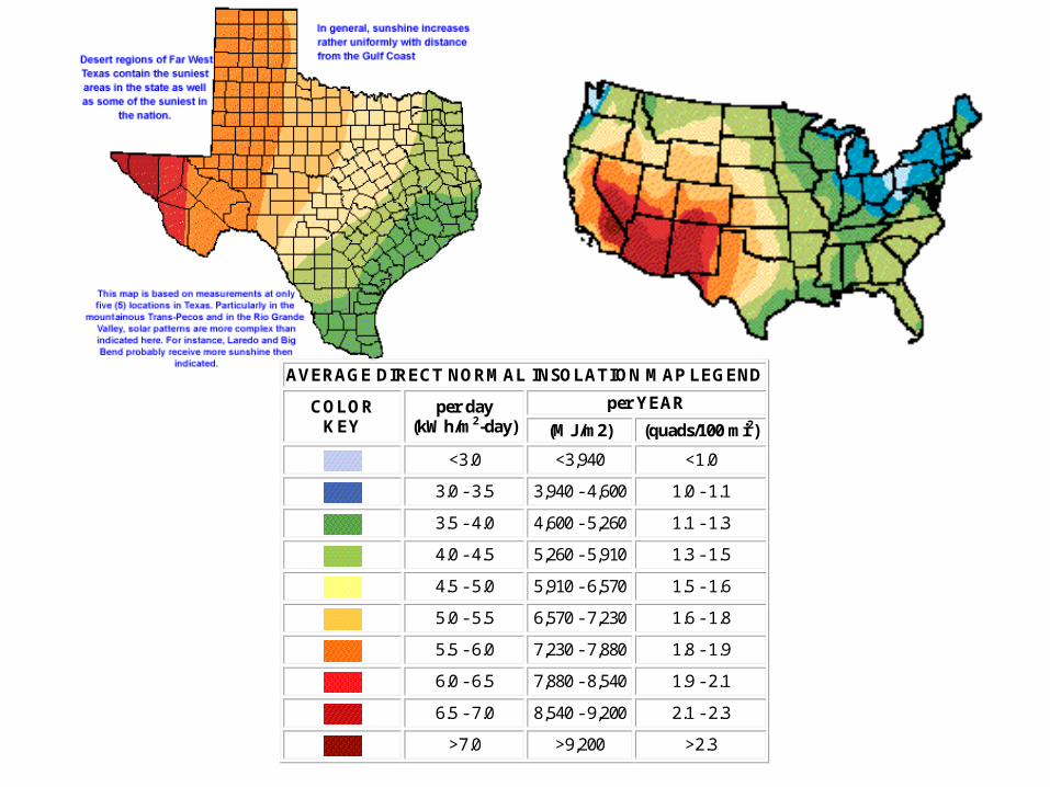
AVERAGE DIRECT NORMAL INSOLATION MAP LEGEND
COLOR KEY
per day (kWh/m2-day)
per YEAR (MJ/m2) (quads/100 mi2)
<3.0 <3,940 <1.0
3.0 - 3.5 3,940 - 4,600 1.0 - 1.1
3.5 - 4.0 4,600 - 5,260 1.1 - 1.3
4.0 - 4.5 5,260 - 5,910 1.3 - 1.5
4.5 - 5.0 5,910 - 6,570 1.5 - 1.6
5.0 - 5.5 6,570 - 7,230 1.6 - 1.8
5.5 - 6.0 7,230 - 7,880 1.8 - 1.9
6.0 - 6.5 7,880 - 8,540 1.9 - 2.1
6.5 - 7.0 8,540 - 9,200 2.1 - 2.3
>7.0 >9,200 >2.3
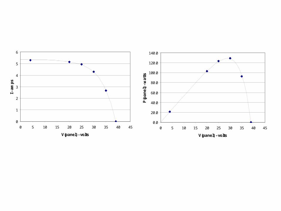
0
1
2
3
4
5
6
0 5 10 15 20 25 30 35 40 45
V(panel) - volts
I - a
mp
s
0.0
20.0
40.0
60.0
80.0
100.0
120.0
140.0
0 5 10 15 20 25 30 35 40 45
V(panel) - volts
P(p
an
el)
- w
att
s
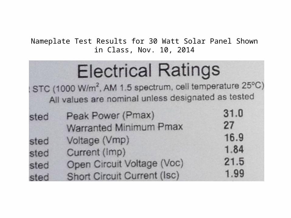
Nameplate Test Results for 30 Watt Solar Panel Shown in Class, Nov. 10, 2014
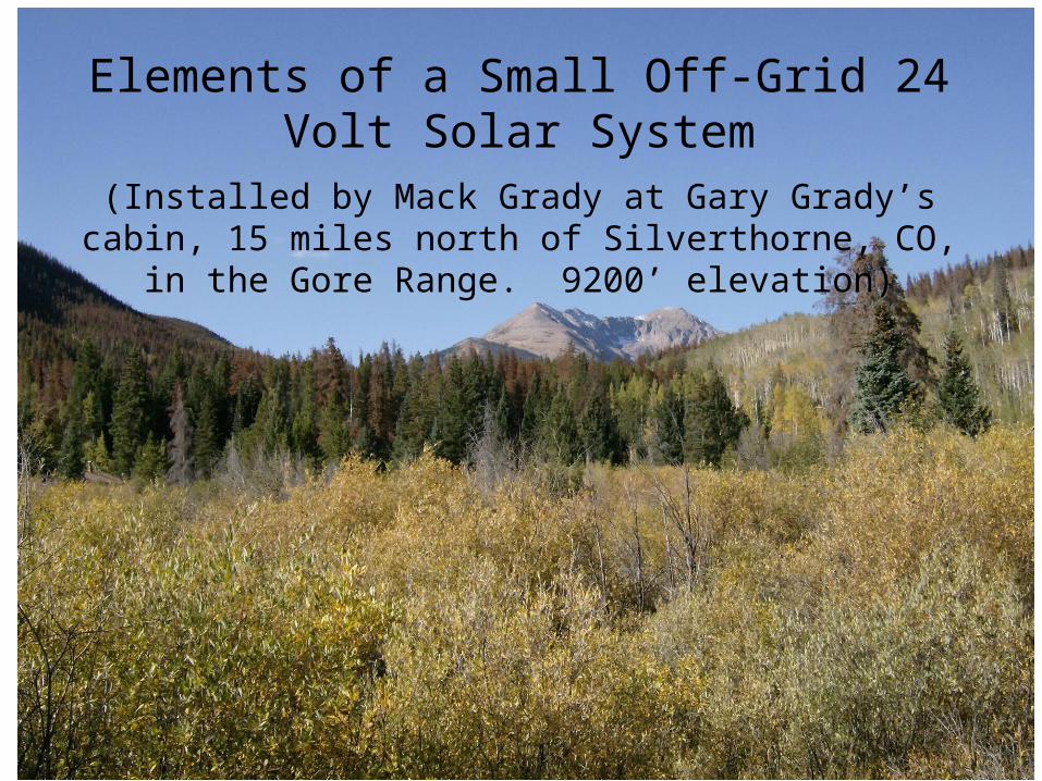
Elements of a Small Off-Grid 24 Volt Solar System
(Installed by Mack Grady at Gary Grady’s cabin, 15 miles north of Silverthorne, CO, in the Gore Range. 9200’
elevation)
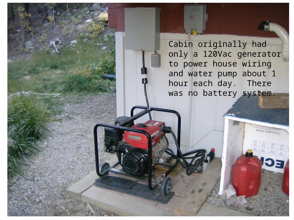
Cabin originally had only a 120Vac generator to power house wiring and water pump about 1 hour each day. There was no battery system.
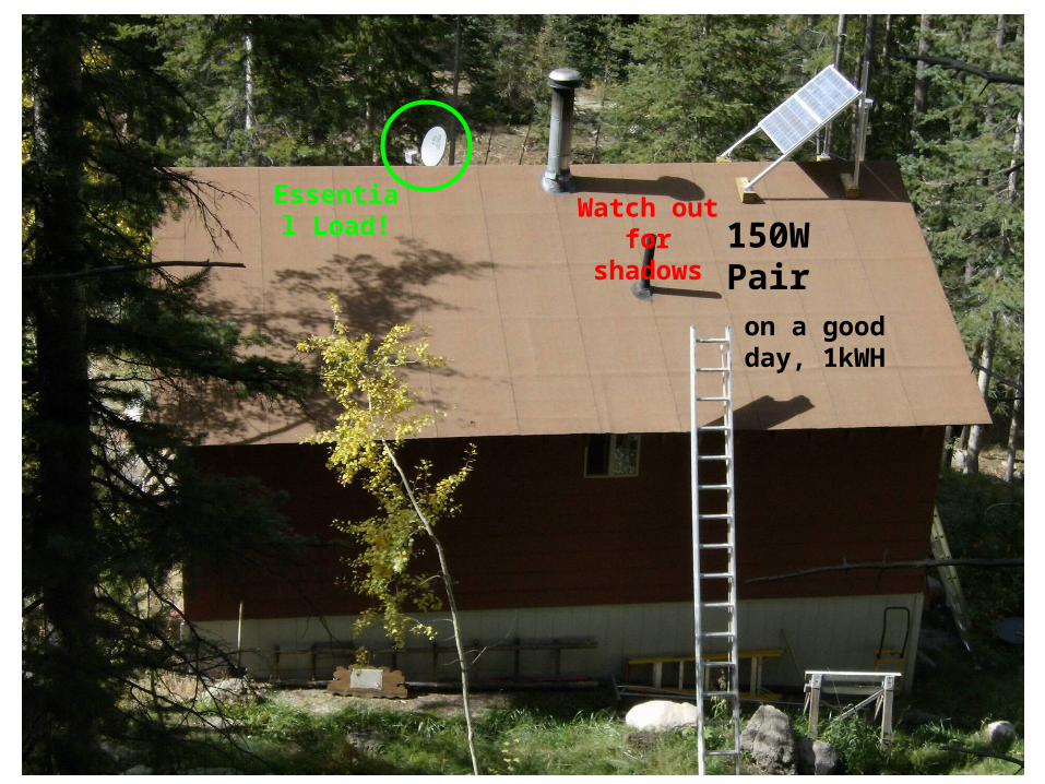
150W Pairon a good day, 1kWH
Watch out for
shadows
Essential Load!
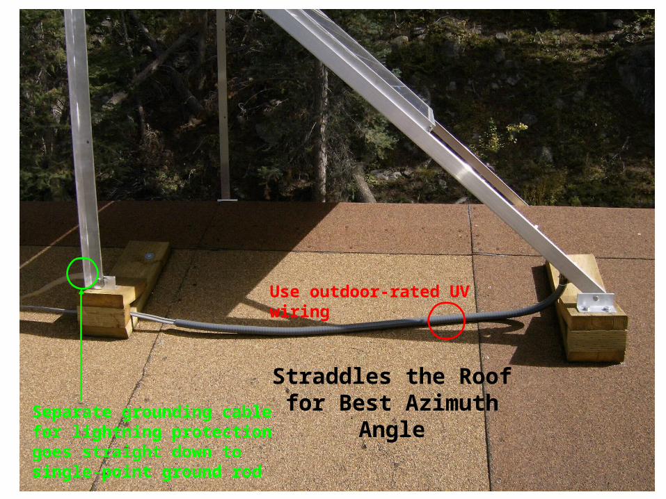
Straddles the Roof for Best Azimuth AngleSeparate grounding cable for
lightning protection goes straight down to single-point ground rod
Use outdoor-rated UV wiring
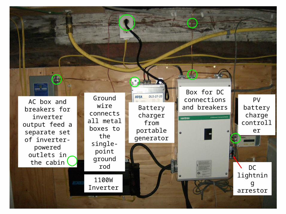
Box for DC connections and breakers
PV battery charge
controller
1100W Inverter
AC box and breakers for
inverter output feed a separate set of inverter-
powered outlets in the cabin
DC lightning arrestor
Ground wire connects all metal boxes
to the single-point ground rod
Battery charger from
portable generator
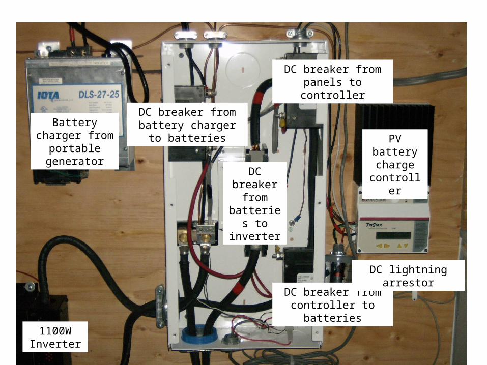
DC breaker from panels to controller
DC breaker from controller to batteries
DC breaker
from batteries to
inverter
DC breaker from battery charger to
batteries
Battery charger from portable
generatorPV battery
charge controller
1100W Inverter
DC lightning arrestor
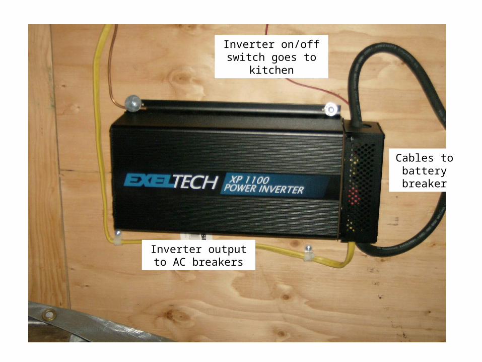
Inverter on/off switch goes to kitchen
Inverter output to AC breakers
Cables to battery breaker
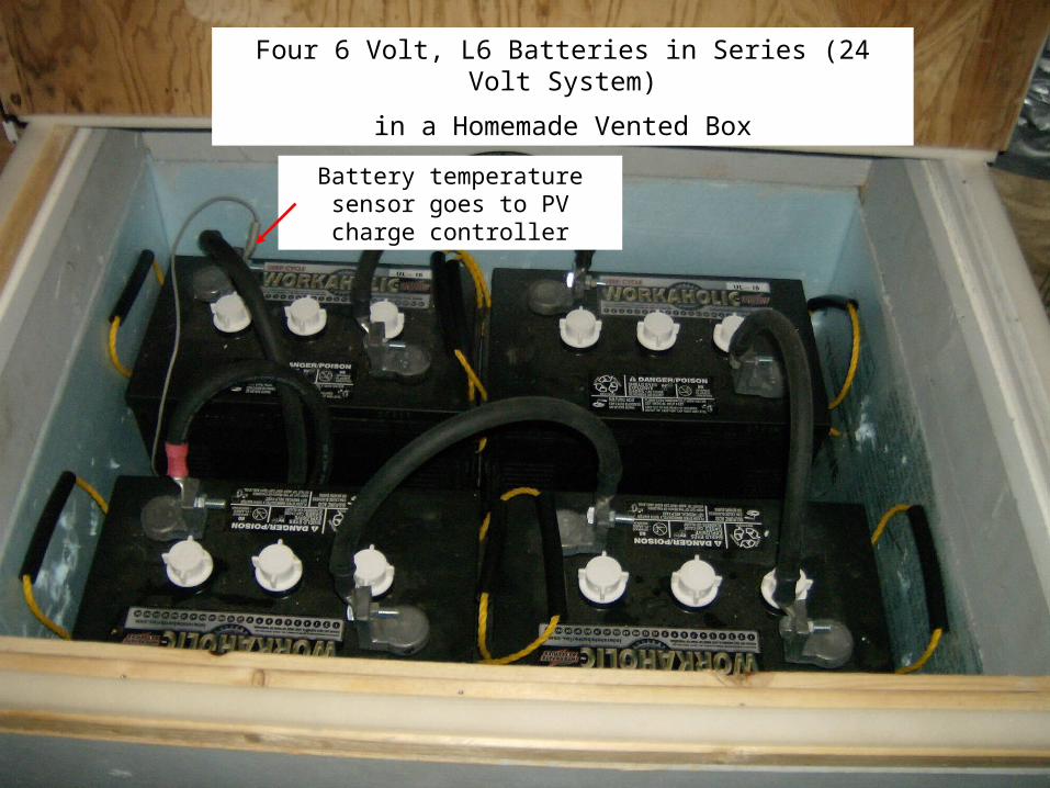
Four 6 Volt, L6 Batteries in Series (24 Volt System)
in a Homemade Vented Box
Battery temperature sensor goes to PV charge controller

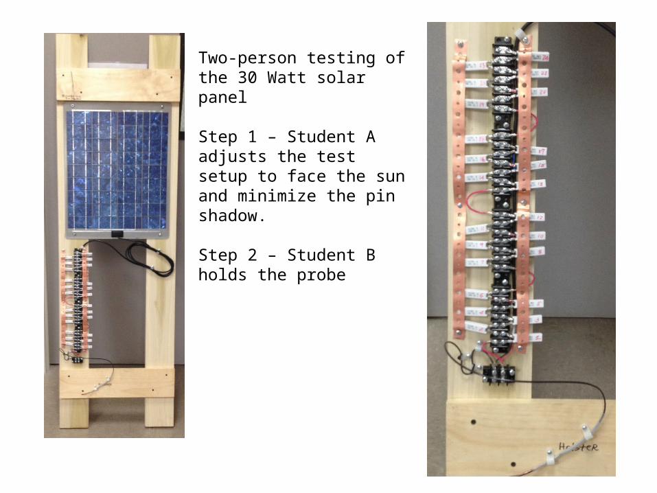
Two-person testing of the 30 Watt solar panel
Step 1 – Student A adjusts the test setup to face the sun and minimize the pin shadow.
Step 2 – Student B holds the probe