Embed Size (px)
Citation preview

NANO-MULTILA YERED SELF-ADAPTIVE HARD PVD
COATINGS FOR DRY HIGH PERFORMANCE MACHINING

NANO-MULTILAYERED SELF-ADAPTIVE HARD PVD COATINGS FOR DRY
HIGH PERFORMANCE MACHINING
By
LI NINO, B. Sc., M. Sc. (Mechanical Engineering)
A Thesis
Submitted to the School of Graduate Studies
in Partial Fulfillment of the Requirements
for the Degree
Doctor of Philosophy
McMaster University
Hamilton, Ontario, Canada
© Copyright by Li Ning, 2007

DOCTOR OF PHILOSOPHY (2007)
(Mechanical Engineering)
McMaster University
Hamilton, Ontario, Canada
TITLE:
AUTHOR:
SUPERVISORS:
Nano-multilayered Self-adaptive Hard PVD Coatings for Dry High
Performance Machining
Li Ning, B. Sc., M. Sc. (Mechanical Engineering)
Dr. M. Elbestawi and Dr. S. C. Veldhuis
Department of Mechanical Engineering
McMaster University
MUNBER OF PAGES: xxiii, 218
ii

Abstract
In this research~ quaternary nitride nano-multilayered coatings of the form
TiAICrN/MexN were comprehensively characterized. Based on this research
principles which can be applied for guiding coating design were developed using the
concept of self-adaptability.
Comprehensive studies were performed on the following aspects: the
tlibological properties of the coatings at elevated temperatures, tool life, and cutting
forces, tribo-oxide formation, wear mechanisms and wear progression, chip
characteristics and the mechanisms of chip formation. The techniques applied for
comprehensive characterization of the coatings were mainly Scanning Electron
MicroscopelEnergy Dispersive Spectrometer (SEMIEDS) and X-ray Photoelectron
Spectroscopy (XPS).
The concept of self-adaptability as applied in this research is defined as the
ability of a system to provide an improved response to an external stimulus such as
friction, temperature, stress and strain. Self-adaptability plays a role in the fonnation
of tribo-oxides on the tool surface under the elevated temperatures associated with
dry high performance machining and the tribo-oxides formed in this case work as
either liquid or solid lubricants in the cutting zone depending on their respective
melting points. The tribo-ceramics (AI-O, W -0, Nb-O and Cr-O) formed during
cutting process, were found to be extremely beneficial for an improvement on tool
performance. They provided a synergetic action which served to protect the cutting
iii

tool by 1) lubricating the cutting zone to reduce friction, 2) insulating the substrate
surface from oxidation as well as thermal attack, and 3) dissipate the energy during
friction to reduce cutting edge and surface damage. However, due to high stress
generating during high performance machining the liquid tribo-oxide lubricants did
not provide any significant improvement in tool life. This was attributed to an
inability to retain them in the cutting zone due to high contact pressures. Also these
liquid phase formations on the surface were found to cause the spallation of the
coating layers.
The adaptability of the coating also affects the chip formation process over the
life of the tool. Among the parameters of the chips used to characterize wear behavior
of a cutting tool, one of the key factors was the contact length between the chip and
the tool rake face. The ability to maintain an optimal contact length was a major
factor for achieving a long tool life. Too short of a contact length results in a short
tool life because of excessively high stress concentration on the cutting edges. It was
found that slight seizure was needed within the running-in stage to obtain a certain
contact length and the ability to continuously provide excellent lubricity had a
significant contribution to reducing further growth in seizure intensity.
Typically saw-tooth chips were generated except when a new sharp cutting
edge with good lubricity was used. In this case continuous chips were observed. The
cross-sections of saw-tooth chips revealed four deformation zones, i.e., white layer
zone, friction zone, primary shear zone and a less deformed zone as a result of the
combined effect of strain hardening, thermal softening, quenching phenomena and
tV

saw-tooth chip formation. The chip temperature estimation indicated that the cutting
tool experienced a temperature of approximately 850 to 1100°C or above at a cutting
speed of 220 mlmin to 300 mlmin. The study of chip formation further confirms that
lubricity, ability to dissipate energy and thermal stability are the most important
properties for coated tools to achieve a long tool life.
Among the adaptive coatings investigated in this research, the nano
multilayered TiAICrN/NbN coating achieved excellent tool performance due to its
enhanced self-adaptive properties under elevated temperatures. The tool life achieved
with the TiAICrNlNbN coated tool was increased by more than four times as
compared to the best commercial available nano-crystalline coating TiAICrN. The
TiAICrNINbN coated tools are able to yield an acceptable tool life even when the
cutting speed reached 400 mlmin and hence makes a great contribution to
productivity improvement.
A coated tool should be treated together as the coating controls the tool life
while both the structure and the properties of the substrate material have a great
impact on the performance of the cutting tool as well. A fine-grained substrate
material possesses the combined properties of both high toughness and high hardness
and had a significant contribution to tool performance especially for the severe
cutting conditions under which the substrate was graduaJly exposed at the cutting
edge as wear progressed,
Overall in the on-going effort to improve wear resistance of a hard coating it
was found that between the two ways to improve tool performance, i.e. hardness
v

improvement as represented by superhard nano-composite coatings such as a
TiAlN/Si 3N4 coating and adaptability improvement by adaptive nano-Iaminated
TiAICrN/MexN coatings, the latter was more beneficial for tool life enhancement
under the proposed cutting conditions.
vi

Acknowledgements
First and forenlost I would like to express my gratitude to my supervisors Dr.
Elbestawi and Dr. Veldhuis for their continuous guidance, critical review of my work and
support throughout the research.
I would like to express my special thanks and appreciation to Dr. Fox-Rabinovich
and Dr. Dosbaeva for their detailed discussions, constructive suggestions and great help
during the project work.
I want to take the chance to thank my committee members Dr. Provatas and Dr.
Shankar for their supervisory insight into my work and annual guidance.
I would also like to express my appreciation to Dr. Koproch, Jim Mclaren and
Warren Reynolds who helped me with sample preparation, SEMfEDX analysis and the
preparation of the experimental tests. I also want to thank Jeff, AmI, Etienne and
Stephane for their help.
This work was n1ade possible by the incredible foresight of Kobe steel. Funding
for this research came from the following organizations: Kobe Steel, McMaster
University, NSERC and ~OS. Their support is gratefully acknowledged.
With family's help, my dream can become true. I would like to thank my son,
Weiyi, my daughter, Joyce, my mother and my parents-in law for their understanding,
patient and support. My special thanks to Weiyi, for his great help on taking care of his
little sister.
Finally, to my husband, without your help this could not have been possible.
Vll

Contents
Abstract iii
Acknowledgements vii
List of Illustrations xiii
List of Tables xix
Nomenclature xxi
Chapter 1 Introduction 1
1.1 Mati vation ., .............................................................................. 3
1.2 Research Objectives .................................................................... 4
1.3 Thesis Outline .......................................................................... 5
Chapter 2 Literature Review 7
2.1 Introduction of Dry High Speed Machining (HSM) .............................. 7
2.2 Tool Life, Tool Wear and Wear Mechanisms .................................... 12
2.2.1 Tool Ufe and tool wear ........................................................ 12
2.2.2 Wear mechanisms ............................................................ 16
2.2.3 Factors affecting tool wear ................................................... 19
2.3 Cutting Phenomena in High Speed Machining (HSM) ......................... 22
2.3.1 Cutting temperature., ............... , ...... , ......... , ....................... 22
2.3.2 Tool wear mechanisms under high temperature ....... , ..... , ..... , .. , .. , 26
2.3,3 Chip f()rmation , .. , ...... , ............. , ........ , ....... , ........ , ............. 28
2.3.4 Cutting forces .. , ........ , ....... " .... , ...... , ................ , .......... , ..... 36
V111

2.4 Coating Deposition Technology .................................. , ................ 37
2.4.1 CVD (Chemical Vapor Deposition) ....................................... 38
2.4.2 PVD (Physical Vapor Deposition) .......................................... 41
2.4.3 Hyblid vacuum deposition processes ...................................... 46
2.5 Recent Developments in Hard Coatings .......................................... 50
2.5.1 MUlti-component coatings ................................................... 50
2.5.2 Multiple-layer coatings ...................................................... 52
2.5.3 Superlattice coatings ......................................................... 52
2.5.4 Dispersionlmultiphase coatings ............................................. 53
2.5.5 Nano-structured coatings ..................................................... 54
2.5.6 Self-lubricating coatings ..................................................... 54
2.5.7 Self-adaptive/self-organized/smart coatings ............................... 55
2.6 Characteristics of Hard Coatings ................................................... 57
2.6.1 Microhardness ................................................................. 58
2.6.2 Coati ng adhesion ............................................................. 62
2.6.3 Fracture toughness ............................................................ 65
2.6.4 Coefficient of friction ........................................................ 67
Chapter 3 Basics of Coating Development 71
3.1 Requirements of Three Zones in Coating ......................................... 73
3.2 Material Selection for Hard PVD Coatings ........................................ 75
3.3 Effect of Co,ating Structure .......................................................... 77
3.4 Effect of Grain Size ................................................................... 79
IX

3.5 Effect of Additional Alloying Elements ........................................... 80
3.5.1 Chrolnium and yttrium ....................................................... 80
3.5.2 Zirconium and vanadium ......... , .......... , ..... , ........................ ,80
3.5.3 Silicon .......................................................................... 82
3.5.4 Boron ............................................ ,., ............................ 82
3.5.5 Hafn-lum ........................................................................ 83
3.6 Properties of Titanium Based Hard Coatings ..................................... 83
3.6.1 Hardness and hot hardness ............................................... , .... 84
3.6.2 Oxidation resistance ...... , ......... , ............ , ................. ,.,."., .... 85
3.7 Lubricious Coatings ........................................... , ...................... 88
3.7.1 Introduction .................................... , ............................... 88
3.7.2 Oxide fonnation ............................................................... 88
Chapter 4 Self-adaptability under Friction 90
4.1 Friction in ~1etal Cutting ............................................................. 90
4.1.1 Sliding on counterpart or films .............................................. 91
4.1.2 Shearing of welded asperities ............................................... 92
4.1.3 Seizure .......................................................................... 93
4.1.4 Lubrication at interface ....................................................... 95
4.2 Concept of Sdf-adaptability ........................................................ 96
4.3 Tribo-systenl and Stages of Tool Life .............................................. 98
Chapter 5 Experim.~ntal work 101
5.1 Cutting Tool Geometries and Substrate Materials ............................... 101
x

5.2 Experimental Setup for Cutting Tests ............................................ 103
5.3 Detennination of Testing Conditions ............................................. 106
5.4 Deposition of Nano-multilayered PVD Coatings ............................... 115
5.5 Friction Coefficient Measurement ................................................ 117
5.6 Techniques, for coating investigation ............................................. 118
Chapter 6 Results and Discussions 120
6.1 Optimization of TiAICrN Base Layer ............................................ 121
6.2 Nano-multilayered TiAICrNIBCN Coatings .................................... 124
6.3 Nano-multilayered TiAICrNIWN coatings ....................................... 126
6.4 Comparison of Nano-structured Coatings ........................................ 134
6.5 Nano-multi layered TiAICrNlMexN Coatings .................................... 151
6.6 The effect of Contact Length on Tool Performance ............................. 153
6.7 Nano-multilayered TiAICrN/NbN Coatings ...................................... 160
6.8 Wear Progression Study of TiAICrN/NbN Coating ............................ 166
6.8.1 Tool wear and wear mechanisms ........................................... 168
6.8.2 The fonnation of tribo-films ................................................ 172
6.8.3 Chip fonnation ............................................................... 180
6.9 Improvement of Productivity ...................................................... 187
Chapter 7 Conclusions and Future Work 189
7.1 Conclusions ........................................................................... 189
7.2 Recommendations for Future Work .............................................. 192
Xl

References
Appendix A Progress of Wear, Chip Formation and Cutting Forces
Appendix B Typical Variation in Tool Life
Appendix C Tool Life of C-2MB Ball End Mills
XlI
194
213
218
219

List of Illllstrations
Figure 2.1 High-speed ranges in machining various materials
Figure 2.2 Lead-times in production of dies/molds
Figure 2.3 Hardness of cutting tool materials verses temperature
Figure 2.4 A survey of U.S. and global markets on cutting tool materials
Figure 2.5 Development of flank wear vs. cutting time/cutting length
Figure 2.6 Types of tool wear
Figure 2.7 The different mechanisms of tool wear
Figure 2.8 Tool wear factors in machining processes
Figure 2.9 Wear mechanisms vs. cutting temperature
Figure 2.10 Crack initiation and saw-tooth chip formation obtained from quick
stop testi ng
Figure 2.11 Schematic of the shear-localized chip formation process showing various
stages in cycle of chip segmentation
Figure 2.12 Chips at different cutting speed
Figure 2.13 Chips at different feed per tooth
Figure 2.14 Chips generated by sharp and worn tools
Figure 2.15 Deposition processes of thin hard coatings
Figure 2.16 Scheme of chemical vapor deposition
Figure 2.17 the schematJlc layout of PVD (magnetron sputtering) process
Figure 2.18 Scheme of the con ventional direct cathodic arc deposition process
XUI
7
9
10
11
13
14
17
20
27
29
30
32
34
35
38
39
42
43

Figure 2.19 Schematic diagram of hybrid deposition (large area filtered arc deposition-
unbalanced magnetron sputtering): a) top view , b) side view
Figure 2.20 Load-indentation curve
Figure 2.21 Scratch test
Figure 2.22 Experimental results
Figure 2.23 The assessnrlent of coating adhesion strength
Figure 2.24 Schematic illustration of the NanoTest system for impact testing
Figure 2.25 Illustrative impact results on the a-C:H coating samples
Figure 2.26 Linear tribometer
Figure 2.27 pin-on-disk tribometer
Figure 2.28 High temperature pin-on-disk tribometers
Figure 3.1 Three cutting zones
Figure 3.2 The factors the coatings affect during cutting process
49
59
63
63
64
66
67
68
69
70
72
73
Figure 3.3 Requirements and influences on properties of the layer-substrate compound 74
Figure 3.4 Different groups of hard materials with characteristic crystal structures 75
Figure 3.5 Toughness mechanisms in ceramic multilayer materials 78
Figure 3.6 Hardness of a material as a function of the grain size 79
Figure 3.7 Wear behavior of different hard components 83
Figure 3.8 Temperature dependence of microhardness of five common coatings 85
Figure 3.9 Oxidation rate of hard coatings 86
Figure 3.10 Oxidation resistance of PVD coatings 87
Figure 4.1 A schematic representation of dry friction in metal cutting 91
xiv

Figure 4.2 Sticking and sliding zones 94
Figure 5.1 Mitsubishi ball end mills (C-2MB and C-2SB) 102
Figure 5.2 Microstructure of C-2MB ball end miH with hardness HV 1650-1700 103
Figure 5.3 Microstructure of C-2SB ball end mill with hardness HV1950-2000 103
Figure 5.4 Experimental setup for cutting tests 104
Figure 5.5 Solid ball end mill 105
Figure 5.6 Ball end milling operation and chip geometry 105
Figure 5.7 Cutting forces vs. cutting parameters (new sharp tool) 109
Figure 5.8 Cutting forces vs. cutting parameters (worn tool, VB=0.10 mm) 110
Figure 5.9 Comparison of the effect of cutting parameters on new and worn tools 111
Figure 5.10 Defonned chip shape vs. cutting parameters (new tool) 112
Figure 5.11 Cross-sectional TEM image of nano-multilayered TiAICrN/WN coating 116
Figure 5.12 A schematic diagram of friction test apparatus 118
Figure 6.1 Tool life of TiAICrN monolayer coatings 122
Figure 6.2 SEM images of three base coatings at the end of tool life (C-2MB) 123
Figure 6.3 Tool wear curves of TiAICrNIBCN coatings 125
Figure 6.4 SEM images of the worn tools at cutting length of 30 m 125
Figure 6.5 Tool wear of TiAICrN and TiAICrNIWN coatings vs. cutting length 127
Figure 6.6 SEM image and EDX elemental maps of the worn flank surface of
ball end mill with TiAICrNIWN PVD coating 129
Figure 6.7 SEM image and EDX elemental maps of the worn rake surface of
ball end mill with TiAICrNIWN PVD coating 130
xv

Figure 6.8 X-ray photoelectron spectra of Ti, Al and W for the worn surface of
ball end mill with nano-multilayered TiAICrNIWN coating
Figure 6.9 TEM images of the worn surface of ball end mill with TiAICrNIWN
coating with diffraction patterns
Figure 6.10 Friction coefficients of nano-structured coatings
Figure 6.11 Tool wear curves of nano-structured coatings
Figure 6.12 Maximum resultant forces of nano-structured coatings
Figure 6.13 SEM images of chip shape
Figure 6.14 SEM image and EDX spectrum of flank face of ball end min with
132
133
135
136
137
138
AITiN/ShN4 coating 141
Figure 6.15 SEM image and EDX spectrum of flank face of ball end mill with
TiAICrN/BCN coating 142
Figure 6.16 SEM image and EDX spectrum of flank face of ball end mBl with
TiAICrN coating 142
Figure 6.17 SEM image and EDX spectrum of flank face of ball end mill with
TiAICrNIWN coating 143
Figure 6.18 SEM images of chip cross-sections 148
Figure 6.19 Microhardness of the chips vs. the distance from tool/chip interface 149
Figure 6.20 Tool wear curves of ball end mills coated with TiAICrN based
coatings (cutting speed of 300 m1min) 153
Figure 6.21 SEM images of chip shapes and undersurfaces (Ti25Al65Cr10N) 154
xvi

Figure 6.22 SEM images of chip shapes and undersurfaces (TiAICrNtraN) 156
Figure 6.23 SEM images of chip shapes and undersurfaces (TiAICrN/CrN) 157
Figure 6.24 SEM images of chip shapes and undersurfaces (TiAICrN/WN) 158
Figure 6.25 SEM images of chip shapes and undersurfaces (TiAICrNlNbN) 159
Figure 6.26 Coefficient of friction of TiAICrN/NbN coatings vs. HI3 steel 163
Figure 6.27 Tool life with different TiAICrNlNbN coatings deposited on C-2SB 164
Figure 6.28 Comparison of three TiAICrNlNbN coatings at the cutting length
of 100 m 165
Figure 6.29 Cutting forces vs. cutting length (TiAICrNINbN (4%» 167
Figure 6.30 SEM images and EDX results of ball end mill with TiAICrNINbN
coating during the wear progress 170-171
Figure 6.31 XPS of the worn surface of the TiAICrNINbN coated tool 174
Figure 6.32 HREEL spectra of the worn surface of the TiAICrN/NbN coated tool 176
Figure 6.33 Element mapping of flank face ball end mill with TiAICrNINbN
coating at the cutting length of 200m 178
Figure 6.34 Element mapping of rake face of ball end mill with TiAICrNINbN
coating at the cutting length of 200m
Figure 6.35 SEM images of chip shapes and surfaces (TiAICrNINbN)
Figure 6.36 SEM images of chip cross-section at different cutting lengths
(TiAICrNINbN)
Figure 6.37 Four zones of saw-tooth chips (cutting length of 30 m)
Figure 6.38 SEM images of chip cross-sections (1- secondary shear zones)
xvii
179
181-182
183-184
185
186

Figure 6.39 Tool life curves of the coated tools with TiAICrNlNbN coating
Figure 6.40 Cutting lengths vs. cutting speeds when flank wear is 0.25 mm
Figure A.l The effect of tool wear on tool surface, chip shape and chip type
Figure A.2 Cutting forces at cutting length of 0.2 m
Figure A.3 Cutting forces at cutting length of 50 m
Figure A.4 Cutting forces at cutting length of 100 m
Figure A.5 Cutting forces at cutting length of 200 m
Figure A.6 Cutting force progress along X axis
Figure A.7 Cutting force progress along Yaxis
Figure A.S Cutting force progress along Z axis
Figure A.9 Resultant cutting force progress
Figure B.l Tool life of C .. 2SB ball end mills with TiAICrNlNbN coatings deposited
187
188
213
214
214
215
215
216
216
217
217
by sputteri ng power of 1.0 kv 218
Figure C.l ToolHfe of C-2MB balI end mills with TiAICrN/NbN coatings deposited
by various sputtering powers 219
xviii

List of Tables
Table 2.1 Properties of advanced cutting tool materials
Table 2.2 Thermal expansion coefficients
Table 3.1 Chemical compositions and weight gain after isothermal oxidation
10
65
tests of the ternary TiAICr-based alloys doped by Hf, Y, Si and Zr 87
Table 5.1 Chemical components of uncoated ball end mills 102
Table 5.2 AISI H13 chemical composition 106
Table 5.3 Cutting parameters 108
Table 5.4 Cutting conditions 114
Table 6.1 Chemical composition of base layer 122
Table 6.2 Composition and properties of TiAICrN and TiAICrNIWN coatings 127
Table 6.3 The properties of commercial and experimental coatings 134
Table 6.4 Chip temperature vs. chip color 140
Table 6.5 Chip color vs. chip temperature 140
Table 6.6 Chip color vs. chip temperature with/without air blow 140
Table 6.7 Phase composition on the chips undersurface 150
Table 6.8 Oxides and their melting points 152
Table 6.9 Composition and properties of the coatings corresponding to the
power of the sputtering source 162
Table 6.10 Correlation of wear to cutting forces and the percentage of force increase 167
Table 6.11 Specific electro-resistance (SER) of different oxides vs. temperature 175
xix

Table 6.12 Chip color vs. chip temperature (TiAICrNlNbN (4 at. %)
Table 6.13 Material removal rate vs. cutting speed
xx
186
188

Nomenclature
WI Total work
We Elastic work
Wp Plastic work
Ke Elasticity index
Ke Plasticity index
Pmax Maximum load
~oadillg Loading force
~ml()adil1g Unloading force
h Indentation depth
dlz Differential indentation depth
hi Maximum penetration depth
hr Residual depth
hI' Effecti ve penetration depth
Er Reduced elastic modulus
Ej Elastic modulus of film
Ei Elastic modulus of indenter
XXl

s Contact stiffness
A Projection of contact area between the indenter and the coating specimen
a A constant
k A constant
H Hardness
F T Tangential force
Normal force
Cutting force component in X axis
Cutting force component in Y axis
Cutting force component in Z axis
Resultant cutting force
f.1/'ff Effecti ve friction coefficient
Apparent contact area
True contact area
c Constant
J1 Coefficient of friction
True shearing stress
True normal stress
Shearing stress of film
Shearing stress of soft material
xxii

t1.U
D
K
e
N
11
d
K
Shearing stress of sticking zone
Shearing stress of sliding zone
Energy in a frictional body
Transformed energy
Internal energy change of a frictional body
Chip thickness
Pick feed I step over distance
Depth of cut
Diameter of ba1l end mill
Feed per tooth
Cutting edge angle
Rotational angle
Spindle speed
Number of cutting flutes
Cutting velocity
Maximum cutting velocity
Hardness of initial grain size
Diameter of grain
Constant
xxiii

PHD THESIS - LI NING MCMASTER - MECHANICAL ENGINEERING
Chapter One
Introduction
Dry machining, hard machining and high speed machining are modem
manufacturing processes. Presently, an increasing number of D1anufacturers are using dry
high speed machining of hardened materials over conventional processes to reduce costs
and minimize their impact on the environment. High speed machining is preferred by
industries, especially die/mold, automotive and aerospace industries, due to the
advantages of high material removal rate, close to net shape surface quality, relatively
low cutting force, high dissipation of heat by chip removal and greatly reduced polishing
times for dies/molds. A typical example application for dry high speed hard machining is
the manufacturing a die from a hardened block of tool steel.
As cutting speeds increase cutting temperatures also go higher especially with dry
machining of hard materials. In these cases, the cutting tools lose their typically excellent
room temperature properties which results in an extremely short tool life. In order to
achieve an acceptable tool life, dry high speed hard machining requires cutting tool
materials with high hot hardness, improved fracture toughness, excellent adhesion,
friction reduction properties, good diffusion and oxidation resistance at these high
temperatures. Coating technology, involving the deposition of hard thin films onto the
1
PHD THESIS - LI NINO MCMASTER - MECHANICAL ENGINEERING
tool, has the potential to provide the required high temperature properties for the cutting
tools in these applications. Today, more than 80% of machining operations are conducted
with coated tools. Among the types of coatings available on the market, titanium-based
hard thin films are most commonly used. This is due to the fact that they tend to improve
the wear resistance in many cutting applications by reducing friction, adhesive wear,
diffusive wear and oxidation wear, overall protecting the tool from thennal attack and
reducing the mechanical stresses on the substrate.
There are two commonly used deposition methods, i.e., Chemical Yapor
Deposition (CYD) and Physical Yapor Deposition (PVD). Due to the type of residual
stress fonned during the coating deposition process, PVD coating is more suitable for
intermittent cutting processes like ball nose end milling which is studied in this research.
Every coating has its lin1ited maximum working temperature. Beyond this
temperature the coating loses its protective properties. For example, the maximum
working temperatures of TiN, TiAIN and TiAICrN coatings are approximately 600°C,
800°C and IOOO°C, respectively. However, under severe cutting conditions the cutting
temperature could exceed I 100°C, and commercial available coatings are not able to give
an acceptable tool life under such high temperatures. Therefore, coatings that are able to
survive the high cutting temperatures experienced in the proposed application are
critically needed.
2

PHD THESIS - LI NING MCMASTER - MECHANICAL ENGINEERING
1.1 Motivation
Identifying and refining a coating able to operate in a high cutting temperature
environment and tuning the operating conditions to best utilize the desirable properties of
a coating is the inspiration for this research. There are two possible ways to approach
this challenge. One is to develop super hard coatings with high hot hardness so that the
tool can still maintain sufficient strength, hardness and toughness under high temperature.
However, high hardness is usually accompanied with brittleness, and high brittleness is a
poor property for an interrupted process like milling making it susceptible to the impact
forces generated as the cutter enters and exits the cut. The other approach is to develop
coatings with excellent lubricity properties that lubricate the cutting zone and hence
decrease the cutting temperature.
Generally, under aggressive cutting conditions the tool/chip contact in the sticking
zone on the rake face of the tool reaches nearly 100% due to the high contact stresses
generated during the cutting process. In this case cutting fluids can hardly penetrate into
the tool/chip interface region. Thus to meet the lubricity needs in the tool/chip contact
region the concept of "self-adaptivity" is applied to coating design. A self-adaptive
coating in this case refers to a coating that naturally generates beneficial tribo-films
(tribo-oxides) on the surface of the tool under the conditions experienced during
machining. These films serve to reduce the coefficient of friction, overall improving the
cutting conditions and hence prolonging the life of the tool.
3

PHD THESIS - LI NING MCMASTER - MECHANICAL ENGINEERING
The structure of the coating also plays a major role in determining the fracture
toughness of a coating. It has been found that nano-multilayered or superlattice coatings
provide better resistance to micro-chipping and crack propagation, as compared to
monolayer coatings. This is accomplished by arresting the crack propagation within the
layers of the coating. The multilayered coating also helps to transfer elements to the tool
surface, which serves to replenish the tribo-film formation process in the tool/chip
contact region. Therefore, nano-multilayered TiAlCrN based PVD coatings were selected
for detailed study in this research.
1.2 Research Objectives
The major goa] of this research is to find advanced coatings which greatly
increase productivity and prolong tool life under the severe cutting conditions associated
with dry high speed machining of hardened materials.
Another goal was to understand why a particular coating performed better than
another. To this end detailed investigations into the phenomena taking place in the
cutting zone were carried out including: friction in cutting zone, formation of tribo-oxides,
tool life, as welJ as investigations into wear types and wear mechanisms, chip types and
mechanisms of chip formation, cutting force, and cutting temperature.
The last goal was to look for ways to extend this benefit through refining the
coatings and tuning the cutting conditions to get higher performance tooling and thus
4

PHD THESIS - LI NING MCMASTER - MECHANICAL ENGINEERING
develop a framework that coating companies and end users can use to develop coatings
and processes for other dry high perfonnance milling applications.
1.3 Thesis Outline
A short description of each chapter in this thesis is given be10w.
Chapter 1. INTRODUCTION. This chapter first introduces the importance of this
research topic, the motivation of the research, and the research objectives.
Chapter 2. LITERATURE REVIEW. This chapter provides a detailed overview
on dry high speed machining, cutting phenomena associated with high speed machining,
recent developments in hard coatings and characteristics of hard coatings.
Chapter 3. BASICS OF COATING DESIGN. This chapter first describes the
requirements of the cutting zone, how a coating affects the cutting process and the
requirements and functions of the three critical wear zones on a tool, and then discusses
the possible ways to improve the functions of a hard PVD coating to meet the
requirements. Methods include adding additional alloying elements, reducing grain size,
changing coating structure, and designing lubricous coatings.
Chapter 4. CONCEPT OF SELF-ADAPTABILITY. This chapter introduces the
concept of self-adaptability, describes the tribological phenomena taking place in the
cutting zone, and discusses the self-adaptability that takes place in a coating and outlines
how it affects tool service life.
5

PHD THESIS - LI NING MCMASTER - MECHANICAL ENGINEERING
Chapter 5. EXPERIMENTAL WORK. This chapter presents the experimental
setup for the cutting tests, the coating deposition and related coating characterization
techniques.
Chapter 6. RESULTS AND DISCUSSIONS. This chapter shows the results
obtained from this research, especially from the study of TiAICrN/BCN, TiAICrNIWN
and TiAICrNlNbN, and discusses tool life, formation of tribo-oxides, cutting forces,
cutting temperature, tool wear, wear mechanisms and chip formation.
Chapter 7. CONCLUSIONS AND FUTURE WORK
In this chapter, a summary of this research is given; the contributions and findings
from the research are presented; and future research work is recommended as well.
6

PHD THESIS - LI NING MCMASTER - MECHANICAL ENGINEERING
Chapter Two
Literature Review
2.1 Introduction of Dry High Speed Machining (HSM)
The range of cutting speeds used for high speed machining varies with the
workpiece materials being machined. Figure 2.1 shows the generally accepted cutting
speeds for high-speed machining of various workpiece materials [Schulz and Moriwaki,
1992]. For example, a cutting speed of 500 m/min is considered high-speed machining
for cutting alloy steel while this speed is considered conventional when cutting aluminum.
C Transition Range. High -Speed Machinlng Range
AIultrun EElII1 Bl'Of'IZ!aand Brau
CUlRln~~ Steel~ ntanl.lTl
10 100 1.000 10.000
CuWng Speed (mmn)
Figure 2.1 High-speed ranges in machining various materials
[Schulz and Moriwaki, 1992]
7

PHD THESIS - LI NING MCMASTER - MECHANICAL ENGINEERING
The advantages of HSM are reported mainly with regard to the following aspects:
high material removal rates, reduction in lead times, low cutting forces, ability to
dissipate heat through chip removal which results in a decrease in workpiece distortion
and an increase in part precision and surface finish [Fall bohmer, et al., 2000]. The major
industries for HSM applications are the aircraft, automotive and the die/mold industries.
For example, high-speed milling was applied to the machining of aluminum alloys for the
manufacturing of complicated parts used in the aircraft industry. This technology has
been successfully applied based on the significant improvements in machine tools,
spindles and controllers (Tlusty, 1993]. With the development of cutting tool
techn010gies, HSM has been used for machining alloy steels (usually hardness>30 lIRe)
for making dies/molds used in the production of automotive, electronic and plastic
molding components [Dewes and Aspinwall, 1997]. In traditional die and mold
manufacturing, dies/molds were made via the following route: first machined in their soft
condition, then hardened followed by EDM (electrical discharge machining), grinding
and/or hand polishing. In this way, a significant portion of the lead-time was spent
hardening and polishing/manual finishing operations, as illustrated in Figure 2.2. The
cost of machining and polishing was reported as taking approximately two thirds of the
total manufacturing costs [Fallbohmer, et al., 1996]. In modem die/mold manufacturing,
cavities can be directly produced from solid in the hardened tool steels by applying HSM
processes. Using light depths-of-cut at high feed rates (high spindle speed but small feed
per tooth) generates a machined surface very close to the designed geometry. Therefore,
8

PHD THESIS - LI NINO MCMASTER - MECHANICAL ENGINEERING
the polishing time in die/mold manufacturing process is greatly reduced and the lead time
associated with hardening is avoided.
• GERMANY 12 JAPAN
----tOUS --_ .....
PIOCes5 Design TOofpath Machining Manual Tryovl Planning Generation Flnistdog
Figure 2.2 Lead-times in production of dies/molds [Fallbohmer, et al., 2000]
However, the common disadvantages from the applications of HSM are reported
as follows: excessive tool wear, requiring special and expensive machine tools with
advanced spindles and controllers, rigid fixturing, balanced tool holder, and lastly but
most importantly the need for advanced cutting tool materials and coatings [Fall bohmer,
et al., 2000].
Among the cutting tool materials such as HSS (high speed steel), carbide, ceramic,
CBN (cubic boron nitride), PCBN, peD (polycrystalline diamond) and diamond, carbide
is the most common cutting too] material for machining castings and alloy steels. Carbide
tools have a high degree of toughness but poor hardness as compared to CBN and
diamond, as illustrated in Figure 2.3. Table 2.1 lists the properties of common cutting tool
materials. In order to improve the hardness and surface conditions, more and more
9

PHD THESIS - LI NING MCMASTER - MECHANICAL ENGINEERING
carbide tools are coated with hard coatings either by CVD (chemical vapor deposition) or
PVD (physical vapor deposition), as shown in Figure 2.4.
8000
o 100 200 300 400 500 600 700 Temperature', "c
Figure 2.3 Hardness of cutting tool materials verses temperature
[Trent and Wright, 2000]
Table 2.1 Properties of advanced cutting tool materials [Fall bohmer, et a1., 1996]
Toil! malerial~ Cmllmg\
PeD CBt\' we Sir\" AIO Ti~
Miem hllruncss (HV) ('A)(1(1 35<XI 15m I&JO 17m 1600 2(0)
Coefficient of friction against ... led in df)' conlact 0.24 0.6 004 Maximum working lempcnllUrc I C) (1I)() 600 111cnnni conductivity (W/m K) ;()O 100 4H80 15 J5 14 17 TmnwcN: rupture j,lrc~lh (~1Pa) ffl() 965 690 17m 2mo 4MO 750 275 .\.",5
10
TiCK
JOO()
0"': 400
TiAlf'
JJtXl 03 0.5 815

PHD THESIS - LI NINO
USA 1998
USA 2005
25
Uncoated
MCMASTER - MECHANICAL ENGINEERING
o Unooated carbide-II eve coated carbtde o PVO ooatod carbide ClAlumfna .Slalon • Cermet. UJOIamond .CBN l!l Diamond coated
o UOGOaled carbfde e cvo coated carbkM C PVC coaled C81b1de (3A/umina .814100 .Cenneta mOI.mood _caN Cl Diamond coated
Global 1998
Global 2005
15
it
Uncoated
Sialon (Si-Al-O-N) - silicon nitride based material with aluminum and oxygen addition; Cermets
(ceramic plus metallic components)~ CBN (cubic boron nitride)
Figure 2.4 A survey of U.S. and global markets on cutting tool materials
[Trent and Wright, 2000]
11

PHD THESIS - LI NING MCMASTER - MECHANICAL ENGINEERING
Generally, high speed machining involves high cutting temperature so the cutting
tool must be chosen not qnly for its wear resistance, but also for its ability to retain this
wear resistance at an elevated temperature.
Dry high speed machining of hardened steel has become attractive due to its
economic and environmental benefits. For interrupted cutting such as milling, dry
machining is beneficial for reducing thermal shock as well. It is well known that in metal
cutting the contact stresses on the rake face of the tool near the cutting edge are very high
and the degree of contact in the tool-chip interface reaches 100%. This means that the
cutting fluids can hardly penetrate the cutting zone interface [Childs, 2006]. Therefore,
the cutting tool is heated during cut and then cooled down rapidly out of cut if coolant is
used and then heated up again on the next cycle. This may result in significant thermal
cracking problems. However, self-lubricious coatings, which are found to generate
oxidation tribo-films under these conditions, reduce friction and thus heat generation in
the cutting zone. This makes them suitable candidates for dry high speed interrupted
machining applications.
2.2 Tool Life, Tool Wear and Wear Mechanisms
2.2.1 Tool life and tool wear
There is no single universally accepted definition of tool1ife. The life needs to be
specified with regard to the process aims. A common way of quantifying the end of a tool
life is to put a limit on the average or maximum acceptable flank wear or the measured
12
PHD THESIS - LI NING MCMASTER - MECHANICAL ENGINEERING
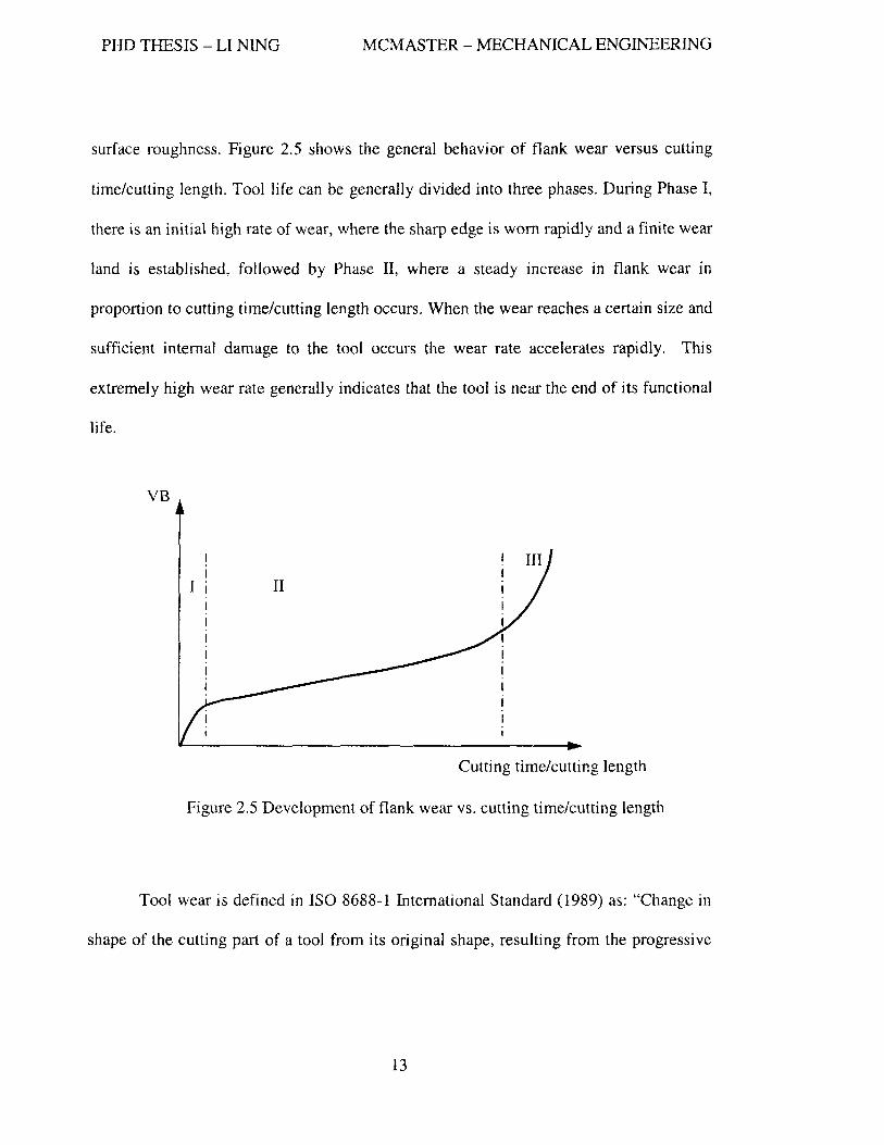
surface roughness. Figure 2.5 shows the general behavior of flank wear versus cutting
time/cutting length. Tool life can be generally divided into three phases. During Phase I,
there is an initial high rate of wear, where the sharp edge is worn rapidly and a finite wear
land is established, followed by Phase II, where a steady increase in flank wear in
proportion to cutting time/cutting length occurs. When the wear reaches a certain size and
sufficient internal damage to the tool occurs the wear rate accelerates rapidly. This
extremely high wear rate generally indicates that the tool is near the end of its functional
life.
VB
Cutting time/cutting length
Figure 2.5 Development of flank wear vs. cutting time/cutting length
Tool wear is defined in ISO 8688-1 International Standard (1989) as: "Change in
shape of the cutting part of a tool from its original shape, resulting from the progressive
13

PHD THESIS - LI NING MCMASTER - MECHANICAL ENGINEERING
loss of tool material during cutting." The commonly recognized tool wear types are
shown in Figure 2.6.
Flank wear (a) and notch (b, c) Crater wear Plastic deformation
- .... -.
~ Built-up edge Chipping Flaking
Edge chipping Thermal cracking Edge fracture or breakage
-- ...
~ Figure 2.6 Types of tool wear [IS08688-1]
These types of tool wear are explained as follows:
Flank wear is the most common type of wear. It generally exists in all machining
applications and it can be observed on the flank face of the cutter and is caused mostly by
tool abrasion and adhesion. Flank wear can affect the sharpness of the cutting edge and
14

PHD THESIS - LI NING MCMASTER - MECHANICAL ENGINEERING
can also generate a wear land which affects the surface finish and dimensional accuracy
of the workpiece.
Notch wear is also called depth of cut notch because its position is typically
associated with the depth of cut. It is usually caused by the extra wear experienced due to
oxides and hard layers on the surface of the workpiece as well as by chips hitting the
edge causing it to chip in this region. Thus the mechanism of notch wear is a combination
of abrasion, adhesion and oxidation.
Crater wear occurs on the rake face. There are two main reasons which cause
crater wear. One is the chip flowing over the rake face of the tool and abrading the tool
material. Another is the diffusion of elements from the tool due to high temperatures in
the tool chip interface. Excessive crater wear usually results in catastrophic breakage of a
tool.
Plastic deformation occurs when there are high temperatures and pressures on
the cutting edge of the tool causing the edge to plastically defonn.
Built .. up edge occurs when portions of the chip adhere to the tool thus changing
the cutting edge geometry. This will impact the cutting force and temperatures in the
cutting zone. Once the built-up edge reaches a critical size it is removed and often takes
a piece of the tool material with it. As the affinity of the tool material to the workpiece
increases the tendency to fonn a built-up edge also increases.
Chipping of the cutting edge occurs when the cutting edge does not have enough
strength to take the cutting loads. Due to the geometries experienced as the tool enters
and exists cut tensile loads on the cutting edge can occur which result in chipping.
15

PHD THESIS - LI NING MCMASTER - MECHANICAL ENGINEERING
Flaking is defined as a loss of tool fragments in the form of flakes from the tool
surfaces. It is mostly observed when coated tool inserts are used but may also occur with
other tool materials.
Thermal cracking is mainly fatigue wear caused by a thermal cyclic load.
Varying chip cross-sections, insufficient coolant and interrupted cuts are the operations
where thermal cracks in tools are most likely to occur. Thermal cracking is usually
perpendicular to the cutting edge.
Mechanical fatigue cracking takes place due to excessi ve shocks. It can occur
when the loads on the tool are varying. These cracks are parallel to the edge.
Fracture is a result of catastrophic failure of the tool. It can happen due to faulty
clamping of the insert, vibration in the system, excessive loads, or at the end of a period
of intensive wear.
2.2.2 Wear mechanisms
During machining, high temperature, high contact pressure, high relative sliding
velocities and the presence of cutting fluid in the tool-chip and tool-workpiece interfaces
are major factors which affect tool wear. A wear mechanism is a result of a set of
physical and chemical processes, which take place in the surface layers of a frictional and
tribological system, as illustrated in Figure 2.7.
16

PHD THESIS - LI NING
I I \ I
,I
\
MCMASTER - MECHANICAL ENGINEERING
-~--- - "~~--+~ .-- ..... ~ ... ~-
CHIP
o IrflfS ION r:::.. ..... WEAR
SOL UTK)N C:.:-,.. WE .... n
ElECTROMECHANICAL C:::::.. WEAR
DELAMINATION t::::... Wl:AR
TOOL EDGE
t 't> I A.BRASIVE AOH£S'Ve: AOt-IESIVE (' WEAR JUNCTION WEAR I
\ 1
---------. ! WORKPIECE i
,/ !.......,......-~--- -- _~------ ___ ~---- '- --i
Figure 2.7 The different mechanisms of tool wear [Kopac, et al., 2001]
Tool wear can be attributed to the following wear mechanisms:
Abrasive wear is caused by a wear process in which a harder material scratches a
softer material under normal pressure. This mechanism is significant for tool wear only
when the workpiece material is very hard or contains hard particles. Hard particles
presented in the chip wear the rake face while hard particles in the machined surface
scratch the flank face. Flank wear and crater wear are the types of wear most frequently
related with this mechanism. Using tool materials with high hardness, melting point and
thennal conductivity can minimize the rate of abrasive wear.
Adhesive wear, also called attrition wear, occurs due to the intimate contact
between the flank face of the tool and the freshly created surfaces on the workpiece and
between the rake face of the tool and the underside of the chip. Several layers of
workpiece material are compressed against the cutting edge at high temperature. After
compression, the layers adhere to the cutting edge and usually become hard like the
17

PHD THESIS - LI NING MCMASTER - MECHANICAL ENGINEERING
process of strength hardening. Some pieces of these layers may break off and take parts
of the cutting edge away, i.e. notching or they may weld onto the tool edge and replace
the real edge and cut the workpiece material, i.e., built-up edge. The welded layers and
points are periodically sheared away and new welds are formed. Hence, built-up edge and
notch wear are common types of wear associated with this mechanism. Adhesive wear
usually occurs at relatively low cutting speeds associated with high pressure/high
temperature on the cutting edge.
Diffusion is the process by which the atoms in the tool material have an affinity
to the atoms in the workpiece material. The diffusion rate depends on the affinity of the
materials, the temperatures in the cutting zone and the concentration gradient of the
penetrating atoms. Chemical wear is mainly associated with crater wear and to a lesser
extent flank wear and notch wear [Braghini and Coelho, 2001].
Oxidation wear is a type of chemical wear, which occurs when metals and
oxygen are in contact. It can be accelerated at high temperature and/or high pressures.
Notch wear is related to this mechanism.
Fatigue wear has two types, i.e., mechanical fatigue and thennal fatigue. The
first is due to the alternating tensile and compression stresses on the cutting edge and the
second is caused by the alternating cycles of heating and cooling. Unlike turning, milling
is dynamic due to its intennittent nature that causes each tooth to undergo both
mechanical and thermal loading and unloading. In every rotation of the cutter, each tooth
has a stress cycle and a heating period followed by a cooling period. The cycling between
heating and cooling produces thermal stresses that may exceed the yield stress of the tool
18

PHD THESIS - LI NING MCMASTER - MECHANICAL ENGINEERING
material which can cause micro cracks. Chipping and catastrophic failure are the main
types of wear related to this fatigue mechanism.
Generally, all forms of wear mechanisms simultaneously contribute to tool wear
however there is usually one or two predominant wear mechanisms depending on the
cutting conditions, the cutting stages, the material chemical composition, as well as
mechanical properties and microstructure.
2.2.3 Factors affecting tool wear
Metal cutting is performed in a machining system (machine tool-spindle system
cutting tool-fixture-workpiece-cutting conditions), All the functional elements in this
system more or less affect tool wear and tool life. Yen, et al. [2002] classified them into
four groups shown in Figure 2.8.
19

PHD THESIS - LI NING MCMASTER - MECHANICAL ENGINEERING
Tool Wear Economy, Part Quality, Process Reliability
material Interface tool machine
structure ~ friction , cutting material dynamics cooling
_~n~ texture ... . .. lubricant coating cutting paramo
material ~ contact L(;) geometry properties r ISBiI
Figure 2.8 Tool wear factors in machining processes [Yen, et a1. 2002]
Workpiece material group indicates that the physical properties of workpiece
material such as mechanical and thennal properties, microstructure, and hardness; affect
cutting forces, cutting temperatures and thus also affect tool wear.
Interface group between workpiece and cutting tool includes coolant and
lubricant, tool-chip contact, cutting parameters (cutting speed, feed rate, axial depth of
cut, radial width of cut). These parameters and conditions definitely affect tool wear.
Cutting tool group indicates that tool substrate materials (such as chemical
composition, structure and grain size), tool coatings and tool geometry (rake angle,
clearance angle, edge preparation, tool radius) are important factors for tool life.
20
PHD THESIS - LI NINO MCMASTER - MECHANICAL ENGINEERING
Machine tool group indicates that the machine tool structure and all the other
pmts active in the cutting process such as spindle-tool holder system, and fixture for
example play an important role in creating a successful cutting operation. Unstable
cutting processes result in a fluctuating overload on the cutter and further lead to
premature failure of the cutting edge by tool chipping and excessive tool wear.
21

PHD THESIS - LI NING MCMASTER - MECHANICAL ENGINEERING
2.3 Cutting Phenomena in High Speed Machining
The basic concept of HSM (high speed machining) involves machining at
considerably higher cutting speeds and feed rates as compared with conventional practice.
This was illustrated in Figure 2.1. Also because of the change in cutting conditions the
cutting phenomena change as well.
2.3.1 Cutting temperature
Like traditional cutting, the heat generated during cutting in HSM is stil1 from
three zones, i.e., the primary shear zone radiating out from the tool tip into the
workpiece/chip interface, the secondary shear zone at the tool/chip interface, and the
contact interface between the clearance face and the machined surface. When the cutting
speed is increased the ratio of heat flow with the chip increases as less time is available
for heat to transfer into the workpiece. This subsequently reduces the total percentage of
the heat flow into the workpiece and the cutting tool [Hirao, et aI., 1998]. It has been
reported that around 80-90% of the heat generated during HSM is transferred to the chip
while 10-15% of the heat goes to the cutting tool and workpiece material [Matsumoto, et
aI., 1986; Dews, et ai., 1999; Dimla D.E.S., 2000; EI-Wardany, et aI., 2000]. When low
thermal conductivity coatings are used to protect the cutting tools, an even higher ratio of
heat goes with the chip. Therefore given the complexity of measuring cutting temperature
the chip temperature in HSM is a reasonable estimate of the cutting temperature.
22

PHD THESIS - LI NING MCMASTER - MECHANICAL ENGINEERING
The relationship between the cutting speed and cutting temperature has been
intensively studied. When Salomon first reported what he termed HSM in 1931 he
proposed that there was a peak cutting temperature at an intermediate cutting speed and
there was a reduction in cutting temperature when cutting speed was increased from that
point. However, most of the literature since this date has concluded that there is no
corresponding reduction in cutting temperature at higher cutting speeds. Instead, cutting
temperature increases as the cutting speed increases [Lezanski and Shaw, 1990; EI
Wardany, et aI, 1996; Chu and Wallbank, 1998; Abrao and Aspinwall, 1997; Liu, et al.,
1997; Leshock and Shin; 1997; Wang et al., 1996]. However, it was found that the heat
conducted into the workpiece reduced as the cutting speed increased because there was a
shorter contact time for heat to penetrate into the workpiece. Also it was stated that the
higher the hardness of the workpiece, the higher the temperature and the deeper the heat
penetrated into workpiece [Matsumoto and Hsu, 1987]. McGee (1979) suggested that
cutting temperature increased with cutting speed up to a maximum value which was
equal to the melting point of the workpiece. When machining soft materials such as
aluminum alloys, it can be said that there is no fixed limit to the cutting speed (without
considering the limitation of machine tool) because the melting point of aluminum alloys
(up to 660°C) is lower than the temperature at which cemented carbide and ceramic tool
materials begin to lose their strength and wear rapidly [McGee, 1979]. However, in the
cutting of iron, steel and other high melting point metals and alJoys, the heat generated
during cutting becomes a controlling factor when selecting cutting speed [Trent, 2000].
23

PHD THESIS - LI NING MCMASTER - MECHANICAL ENGINEERING
Therefore, the limit on cutting speed is actually determined by the properties of the
cutting tools at the elevated temperatures experienced in the cutting zone.
In addition to cutting speed, how the other parameters affecting cutting
temperature has been investigated as well. It was observed that cutting temperature
increased as tool wear increased but feed per tooth did not significantly affect the cutting
temperature (Dewes et aI., 1999J. Ning et al. (2001) concluded that the cutting
temperature increased with cutting speed and axial depth of cut when HSM ball end
milling hardened AISI HI3 steel. Abrao et al. (1996) concluded that the temperature
increased with an increase in cutting speed, feed rate, depth of cut and tool wear when
finish turning hardened AISI H13 steel. Abrao and Aspinwall (1997) found that cutting
temperatures increased with feed rate, depth of cut and tool wear, respectively, when
turning hardened AISI E52100 steel. They also concluded that the thermal conductivity
of cutting tool material played a major role where a higher thermal conductivity of a
cutting tool induced a lower tool/chip interlace temperature. As a result, less heat would
go to soften the chip, but the high heat level into the tool would weaken the tool material.
Wang and Liu (1999) investigated the effect of tool flank wear on the heat transfer,
thermal damage and cutting mechanics when hard turning AISI E52IOO steel and asserted
that the proportion of heat that went into the chip increased as flank wear increased
accordingly, indicating that the heat generated at the tool/chip interface and tool/work
interlace was strongly dependent on the development of the flank wear. EI-Wardany et al.
(1996) concluded that the cutting edge temperature increased with feed and depth of cut
when high speed turning the case hardened AISI 1552 steel. They also investigated the
24

PHD THESIS - LI NING MCMASTER - MECHANICAL ENGINEERING
effect of tool geometry on cutting temperature. It was found that cutting edge temperature
decreased with increasing tool nose radius since larger nose radius promotes heat
conduction. However, by increasing the tool width chamfer the cutting edge temperature
rose due to an increase in the tool/chip contact length. Therefore an optimal tool
geometry exists to achieve a minimum cutting edge temperature. Also the cutting
temperature measured for an intenupted cutting process such as milling is lower than for
continuous cutting such as turning [Dimla, 2000; Stephenson and Ali, 1992; Chou and
Evans, 1999]. The cutting temperature in intermittent cutting depends primarily on the
duration of cutting time and non-cutting time per cut. Overall the temperature increases
as the cutting time per cut increases [Stephenson and Ali, 1992].
In summary, the factors that affect cutting temperature include cutting speed, tool
wear, workpiece material, depth of cut, feed, tool geometry, especially cutting edge
geometry, thermal property of the tool material and type of cutting operation (continuous
or interrupted).
Regarding the determination of temperatures at the tool/chip interface, cutting
tool, workpiece and chip surface, the techniques used for measuring/estimating can be
classified as follows:
);;> Embedded thermocouples and tool/chip thermocouples [Dewes, et aI., 1999].
);;> Metallographic method, i.e., microhardness and microstructure analysis.
);;> Powders of constant melting point.
);;> Thermo-sensitive paints.
);;> Infrared method [Dewes, et aI., 1999; Young and Chou, 1995].
25

PHD THESIS - LI NINO MCMASTER - MECHANICAL ENGINEERING
>- Chip color [Venkatesh et aI., 1993; Ning, Y. et aI., 2001].
In this research chip color is used for estimating the temperature in the cutting
zone.
2.3.2 Tool wear mechanisms under high temperature
Cutting temperature is a major factor that affects tool wear mechanisms, tool life
and surface integrity. Kopac et a1. (2001) stated that low cutting temperatures produce
pressure welding which result in built-up edge (BDE) formation, while high cutting
temperatures trigger diffusion and oxidation processes. Diffusion processes between the
chip and the top rake surface of the cutting edge result in crater wear and oxidation
reactions with the environment which induce scaling of the cutting edge. Koshy et al.
(2002) used PCBN tools machining hardened D2 (HRC 58) and found that chipping
occurred when high speed milling. It was also found that adhesion and attrition were the
governing wear mechanisms responsible for tool wear and that PCBN tools failed by
fracture of the cutting edge. Wear mechanisms verses cutting temperature in continuous
cutting and interrupted cutting have been intensively studied [Loffler, 1994; Kopac et aI.,
2001] and the commonly accepted conclusion shown in Figure 2.9 [Kopac et aI., 2001].
In the lower cutting speed range, the dominant wear mechanisms are abrasion and
adhesion while in the high cutting speed range, tool wear grows exponentially and is
mostly attributed to the rapid increase of diffusion wear. In addition to diffusion wear,
oxidation and also abrasion are the major wear mechanisms in the high cutting speed
range.
26

PHD THESIS - LI NING MCMASTER - MECHANICAL ENGINEERING
Cutting temperature I': (cutting speed, feed etc.)
Figure 2.9 Wear mechanisms vs. cutting temperature [Kopac et a1., 2001]
From a tribological point of view, tool surface protection against wear can be
improved by:
~ Increasing the wear resistance of the tool material surface.
~ Influencing the frictional conditions in the contact zone.
Kopac et al. (2001) stated that in selecting appropriate surface protection to
reduce surface wear, both the technical function of tribological systems together with
variables (load, speed, temperature), and the wear mechanisms which are expected in the
contact zone have to be taken into account.
Generally, if adhesion is the predominant wear mechanism, a surface protection
layer on a tool should have a low inclination to cold weld and low shear strength. The
most efficient ways to reduce adhesion are through sufficient lubrication and cooling,
and thought the proper selection of tool-workpiece materials. Abrasive wear can be
reduced by increasing the hardness of the cutting tool surface either by heat treatment or
27

PHD THESIS - LI NING MCMASTER - MECHANICAL ENGINEERING
by applying very hard protective coatings. When several wear mechanisms are expected,
multistage or combined surface protection should be planned [Fenske, et aI., 1988].
2.3.3 Chip formation
The study of the chips generated during cutting goes back more than a century
and still remains the focus of much attention. Although the goal of machining is to
generate satisfactory machined surfaces the study of chip formation is very important
because of the consumption of energy used in the formation and movement of the chip,
and the main economic and practical problems concerned with metal removal rate, tool
performance and the integrity of machined surface, can be understood by studying the
behavior of the work material as it is formed into a chip and moves over the tool.
Detailed knowledge of the chip formation process is also required for the understanding
of the accuracy and condition of the machined surface of the desired component [Trent
and Wright, 2001].
Chips can be classified into continuous, segmental (also cal1ed serrated or shear
localized or saw-tooth), and discontinuous chips. Basically, the chips generated in hard
machining are referred to as saw-tooth chips. Currently, there are two different theories
associated with saw-tooth chip formation. One is called "crack theory" in which the chip
formation starts with the initiation of a crack at the free sutiace of the workpiece and the
crack fUl1her propagates towards the cutting edge of the tool. The crack soon ceases to
grow at a point where severe plastic deformation of the material exists under higher level
of compressive stresses. The chip segment caught up between the tool rake face and the
28

PHD THESIS - LI NING MCMASTER - MECHANICAL ENGINEERING
crack is pushed out while the material in the plastic region just below the base of the
crack is displaced along the tool rake face thus forming saw-toothed chips [Nakayama, et
aI, 1988; Shaw and Vyas, 1993, 1998; Konig et a1., 1993; Elbestawi et a1., 1996;
Poulachon and Moisan, 1998; Vyas and Shaw, 1999]. Figure 2.10 shows the crack
initiation caught during the cutting process by using a quick stop device. The different
stages of saw-tooth chip formation were identified as well.
Stage 1 Stage 2 Stage 3
Figure 2.10 Crack initiation and saw-tooth chip formation obtained from quick stop
testing [Poulachon and Moisan, 1998] (dry turning 100Cr6 steel HV760, whiskers
reinforced ceramic, V=100 mlmin, f=O.1 mm/rev, d=l mm)
The other theory is called the "adiabatic shear theory" in which a thermoplastic
instability occurs within the primary shear zone and the mechanism of deformation is the
one in which the rate of thermal softening exceeds the rate of strain hardening and is
often referred to as an adiabatic shear process (Figure 2.11) [Komanduri, et al., 1982;
Davis, et al., 1996; Zhen-Bin and Komanduri, 1997; Palmai, 2005; Limido, et al., 2006],
29

PHD THESIS - LI NING MCMASTER - MECHANICAL ENGINEERING
It has been suggested that adiabatic shear may precede crack initiation and propagation
within the uncracked region of the primary shear zone [Vyas and Shaw, 1999].
, t I I ~ , I I
Ch.p " I, ./ ~i_.-..i ____________ - --~5
Figure 2.11 Schematic of the shear-localized chip formation process showing various
stages in cycle of chip segmentation [Zhen-Bin and Komanduri, 1997]
The numbers in the Figure represents:
1. Un deformed surface
2. Part of the catastrophically shear failed surface separated from the following segment due to intense shear
3. Intense shear band formed due to catastrophic shear during the upsetting stage of the segment being formed
4. Intensely sheared surface of a segment in contact with the tool and its subsequent slide along the tool face
5. Intense localized deformation in the primary shear zone
6. Machined surface
30

PHD THESIS - LI NING MCMASTER - MECHANICAL ENGINEERING
BalTY and Byrne [2002] studied the mechanisms of chip formation in machining
hardened steels and they concluded that the primary instability within the primary shear
zone during saw-tooth chip formation is the initiation of adiabatic shear at the tool tip and
propagation partway to the free surface of the workpiece material while failure within the
upper region of the primary shear zone near the free surface occurs through either "crack
theory" or "adiabatic shear theory" depending on the cutting conditions. Under severe
cutting conditions such as high workpiece material hardness and high cutting speed,
failure was caused by ductile fracture; otherwise, failure occurs through large strain
plastic deformation. Increasing workpiece material hardness, cutting speed, un deformed
chip thickness and flank land as well as a more negative rake angle can result in saw
tooth chip formation [Barry and Byrne, 2002; Ekinovic, et al., 2004; Ng and Aspinwall,
2002; Wang and Liu; 1999; Jaspers and Dautzenberg, 2002; Konig, et al., 1984, 1990;
Boeher, 1998; Kishawy and Elbestawi, 1997; Kishawy and Wilcox, 2003; PalDey and
Deevi, 2003].
Konig, et al. (1984) explained the chip formation process in detail. Due to the
negative tool rake angle used in their study high compressive stresses are created both on
the cutting edge and in the material. Owing to the brittleness of the material, the high
compressive stress initially leads not to material flow but to the formation of a crack. This
crack releases the stored energy and acts as a sliding surface for the material segment,
allowing the segment to be forced out between the parting surfaces. Meanwhile, plastic
deformation and heating of the material occurred at the leading edge of the cutting tool.
31

PHD THESIS - LI NING MCMASTER - MECHANICAL ENGINEERING
Once the chip segment has slid away, renewed cutting pressure results in the formation of
a fresh crack and chip segment.
How the cutting conditions affecting chip formation has been investigated
intensively. Boehner, et al. investigated the effect of cutting speed, feed and tool wear on
chip formation in hard ball end milling [Boehner, 1998; Boehner, et al., 1999]. Figure
2.12 shows different chips at different cutting speeds.
Figure 2.12 Chips at different cutting speed [Boehner, 1998]
From Figure 2.12 one can see that sharper chips are generated at higher cutting
speeds while blunt chips are observed at lower speeds. The reason is that the lower
cutting speed allows the heat generated by cutting to remain longer in the cutting zone as
32

PHD THESIS - LI NINO MCMASTER - MECHANICAL ENGINEERING
compared to the cases where higher speeds are used. Thus, the material has more time to
soften and deform plastically. The crack is initiated due to the high pressure in front of
the cutting edge advances towards the tool tip and is seized early in the plastic field
materia1. A new chip fanning cycle is started early and as a consequence the
segmentation frequency increases. The higher the cutting speed is, the less time is left to
soften the material. Once the crack initiates it advances in the direction of the tool tip and
stops in the plastically deformed material zone. Consequently the chips at higher speed
look sharper.
Chip curling at the tip of each chip is a typical phenomenon during the chip
formation in high speed ITlachining. Chip curling occurs because of an immense
temperature increase in the first contact area between the chip and the tool. The
temperature at the underside surface of the chip increases much faster than the free
surface. As the temperature gradient of the chips increases, the resistance to curling
decreases. It is normally expected that chip curling increases at elevated cutting speeds.
However at higher speed, the plastic deformation zone is thinner and also the secondary
shear zone decreases along the chip length, which leads to a decrease in the temperature
gradient between the free surface and chip-tool-interface during the cut. Consequently, an
increase in chip curling is not obviously observed as the cutting speed increases, as
shown in Figure 2.12.
Chip curling is also strongly affected by the feed per tooth as well. Figure 2.13 shows
different curled chips produced at different feeds per tooth.
33

PHD THESIS - LI NING MCMASTER - MECHANICAL ENGINEERING
chip curling dl!pendLng on different feed per to\oth .. ·
Figure 2.13 Chips produced at different feeds per tooth [Boehner, 1998]
There are two phenomena observed from Figure 2.13. One is that chip curling
decreases as feed increases. Another is that chi p segmentation frequency decreases as
feed increases. The first phenomenon can be explained as: an increase of feed increases
the defonned chip thickness. The thicker the chip is the higher its resistance to curling,
even when a high temperature gradient between the chip-tool-interface and the free
surface of the chip exists. At the highest feed per tooth (O.15mm) almost no chip curling
can be observed, while at the llowest feed per tooth (O.OSmm) the chip curls (Figure 2.13).
The second phenomenon can be explained as follows: when feed increases, the deformed
chip thickness is thicker and a higher pressure is imposed on the workpiece material; due
to the higher pressure, the initiated crack propagates at a higher speed towards to tool tip
to relieve the higher energy before it seizes in the softened material zone. Therefore, the
segmentation separated from the workpiece by this crack is larger. Consequently, the
segmentation frequency decreases (Figure 2.13).
Tool wear has a significant influence on chip formation. Figure 2.14 shows that
chip curling decreases and the plastic deformation region gets thicker as the tool gets
worn.
34

PHD THESIS - LI NING MCMASTER - MECHANICAL ENGINEERING
V =317m/mm 3j·=2mm a .. -=O 635mm f[=O 05mm
ChlP deformatton due sharp and W<:>fn tt;.ols·
Figure 2.14 Chips generated by sharp and worn tools [Boehner, 1998]
This phenomenon can be explained in the following way: due to tool wear, more
friction occurs causing extensive rubbing, and hence more heat is generated. This high
cutting temperature in the cutting zone softens the workpiece material and hence, the
plastic deformation occurs more easily. The larger plastic deformation zone stops the
crack earlier and lowers the temperature gradient of the chip which then decreases the
chip curling.
In summary, the frequency of chip segmentation, the degree of chip curling and
the height of the saw-tooth depend on the cutting temperature, cutting pressure/cutting
energy density, temperature gradient of the chip and the time that the chip is retained in
the cutting zone. While all of these factors are related to the cutting conditions such as
cutting speed, feed, depth of cut, tool wear, tool geometry, lubricity in the cutting zone
and the presence of coolant.
35

PIll THESIS - LI NING MCMASTER - MECHANICAL ENGINEERING
2.3.4 Cutting forces
The comparison of wear mechanisms, surface integrity, chip formation and
cutting force in hard machining has not been frequently or critically reported. However
the influences of cutting parameters and flank wear on cutting forces has been studied in
different machining operations. For instance, Elbestawi, et a1. (1996) investigated the
performance of whisker-reinforced ceramic tools in milling nickel-based superalloy and
concluded that the average cutting force reduces with an increase in cutting speed as well
as a lowering axial and radial depth of cut. Wang and Liu (1998, 1999) studied the effect
of flank wear on the forces and temperatures in hard turning. Nakayama, et al. (1988)
indicated that the cutting forces in the machining of hard materials are not necessarily
high due to the following effects:
~ Relatively small plastic deformation of the chip due to crack formation (see
section 2.3.3).
~ Relatively small area of tool-chip contact which reduces the friction force.
» After the cutting parameters that affect the cutting forces, rake angle and flank
wear are the key factors in achieving successful hard machining.
~ Larger negative rake angle on the tool increases the cutting force only a little
while it results in a remarkable increasing in the thrust force.
~ During the machining of hard materials, the high abrasiveness and high cutting
temperature cause rapid tool wear and a worn flank surface with a blunt cutting
edge raises the cutting forces, especially the thrust force, which further accelerates
wear [Nakayama, et aI., 1988].
36

PHD THESIS - LI NING MCMASTER - MECHANICAL ENGINEERING
2.4 Coating Deposition Technology
In recent years, hard thin coating films have been widely applied in cutting tools,
molds and dies, and aerospace components due to their properties of high hot hardness,
low thermal conductivity, low friction coefficient and good erosion resistance. These are
important properties for machining due to the increased demands placed on modem
machining processes such as high speed, dry environments, heavy cutting loads, and
difficult-to-machine materials. Coating technology is one means of achieving good
performance under these critical environments. Figure 2.15 summarizes the coating
deposition processes typically used.
37

PHD THESIS - LI NING MCMASTER - MECHANICAL ENGINEERING
Hard coating
processes
APCVD (atmospheric pressure CVD)
LPCVD (Jow pressure CVD)
PECVD (Plasma enhanced CVD)
Evaporation
Sputtering
Arc vapor deposition
Laser ablation
Ion plating
Hybrid deposition processes
Filament resistive heating
Electron beam heating
DC (diode) sputtering
Magnetron sputtering
Reacti ve sputtering
Figure 2.15 Deposition processes of thin hard coatings
2.4.1 Chemical Vapor Deposition (CVD)
Generally, CVD is the deposition of a solid on a heated surface from a chemical
reaction in the vapor phase. This process takes place in a heated chamber at a temperature
38

PHD THESIS - LI NING MCMASTER - MECHANICAL ENGINEERING
between 850 to 1000°C. This high temperature limits its application to thermally stable
materials like cemented carbide. In this process the coating is formed through the
chemical reactions of different gases as shown in Figure 2.16. The CVD process is well
adapted to the deposition of multi-layered coatings because the process is relatively easy
to regulate using various gases. The latest generation of CVD multi-layered coating for
high-speed machining applications combine CVD and PVD methods. For instance, a
multi-layered TiC+ TiCN+Ah03 coating additionally includes an outer TiN PVD layer.
This layer protects the brittle Ah031ayer against damage during the running-in stage of
wear and improves the adaptability of the CVD multi-layered coating.
CVD'
Figure 2.16 Scheme of chemical vapor deposition [Sandvik Coromant, 1994]
39
PHD THESIS - LI NING MCMASTER - MECHANICAL ENGINEERING
Compared with the PVD coating process, CVD coating does not need an ultra
high vacuum and it has high throwing power for ease of filling deep recesses and other
3D structure. CVD coatings are generally thicker which is good for achieving a longer
tool life however the process is not able to form a coating on a very sharp cutting edge
and it is in general rougher than PVD coatings. In addition, CVD processes usually
generate coatings with tensile residual stress at the surface. For the above reasons, CVD
coatings are usually applied on tools that are used in continuous cutting operations.
In order to reduce the deposition temperature of CVD, a plasma-enhanced CVD
(PECVD) (also called plasma activated CVDIPACVD) coating technique was developed.
PECVD reactors operate under low pressure and do not depend completely on thermal
energy to accelerate the reaction processes. They also transfer energy to the reactant
gases by using a radio frequency induced glow discharge. This plasma enhanced
application results in a significant reduction of deposition temperature down to 450 -
600°C. Now, different types of coatings such as monolayer, multilayer as well as
nano-scale multilayer and nano-composite coatings [Stoiber, et aI., 2000] can be
deposited using this technique on a wide range of substrate materials.
40

PHD THESIS - LI NINO MCMASTER - MECHANICAL ENGINEERING
2.4.2 Physical Vapor Deposition (PVD)
The development of PVD processes in the 1980's boosted the application of
coatings for high speed and hot worked tool steel due to its relatively low deposition
temperature (within ISO-500°C). This is significant as it is below the tempering
temperatures of these steels. Different from CVD processes physical vapor deposition
(PVD) processes are performed in a vacuum and involve the condensation of neutral or
ionized atoms of metals onto the substrate. Different PVD techniques are available for the
deposition of hard coatings (see Figure 2.15).
Four basic elements are generally needed in a PVD process as listed below:
1. A vacuum chamber, evacuated with a pumping unit.
2. A vapor source (i.e., crucible, target).
3. A medium, usually argon based plasma.
4. A receiving area (i.e., parts I substrates) which are typically located opposite to the
vapor source.
Figure 2.17 is a schematic layout of a PVD process based on magnetron
sputtering. In this process the coating material is gradually removed from the metal
target by bombardment with argon ions. At the same time a reactive gas is fed into the
chamber. The gas contains the non-metallic component of the coating such as nitrogen or
carbon. The ionized metal and gas particles are then accelerated against the substrates by
41

PHD THESIS - LI NING MCMASTER - MECHANICAL ENGINEERING
an electric field. On impact they are deposited on the substrates as a thin coating. During
the coating process the substrates are rotated to ensure uniform coating thickness
everywhere.
I-Argon, 2-Reactive gas, 3-Arc Sources (coating material and backing plate)
4-Components, 5-Vacuum pump
Figure 2.17 the schematic layout of PVD (magnetron sputtering) process [Balzers]
In order to increase target utilization and sputtering rates, an "unbalanced"
magnetron process has been designed. In this case the magnetic flux from one pole is
unequal to the other. Unbalanced magnetrons increase ion and electron bombardment of
the growing film and the target utilization by as much as 30-40 wt%.
Figure 2.18 is a schematic diagram of a conventional direct cathodic arc source
deposition. In this technique, the secondary electrons needed to sustain the glow
discharge are emitted either by a thermal or a tunneling effect or by a combination of
both phenomena. This results in very high electron current densities. Thus, arc plasmas
are generally dense and contain a high percentage (60-80%) of metallic species which are
42

PHD THESIS - LI NING MCMASTER - MECHANICAL ENGINEERING
ejected from the target and ionized. This confers a very high level of adhesion of the arc
evaporated coatings, because of the possibility of metallic ion implantation in negatively
polarized substrate(s). Moreover, the adequate polarization of parts with a complex shape
(drills), leads to the synthesis of a homogeneous coating even in the shadowed sides of
the part to be coated. Unfortunately, the evaporation of the target is generally associated
with the ejection of melted particles (droplets) which leads to the fonnation of a large
number of macroscopic defects during the growth of the coating. Thus, the arc
evaporated coatings are relatively rough compared to magnetron sputtered films.
voltage drop zone
Anode N egati vel y biased
substrate to be coated
Figure 2.18 Scheme of the conventional direct cathodic arc deposition process [http://www.arcomac.comltechnology.htmI]
For the deposition of TiAI-based coatings, the following techniques are the most
widely used ones: cathodic arc vapor (plasma or arc ion plating) deposition [Han, et al.,
1996; Wang, 1997; Suzuki, et al., 1998; Eizner, et a1., 1996 Eizner; Ikeda and Sato, 1991];
magnetron sputtering (or sputter ion plating) [ Kukla, 1997; Prengel, et al., 1997;
Lugscheider, et al., 1999; Schaffer and Kleer, 2000]; and combined magnetron and arc
43

PHD THESIS - LI NING MCMASTER - MECHANICAL ENGINEERING
processes [Donohue, et a1., 1997; Smith, et aL, 1997; Schonjahn, et al., 2000; Yamamoto,
et al., 2005]. These PVD processes differ with respect to the type of evaporation of the
metallic components and the plasma conditions employed during the deposition process.
The transition of the metallic component to be deposited from a solid to a vapor phase (in
which metal atoms are ionized in different ways) may be performed by the heating of an
evaporation source (as in cathodic arc) or by sputtering of a target (as in magnetron
sputtering). Cathodic arc and magnetron sputtering techniques allow for the evaporation
of metals with different melting points such as Ti and Al from a Ti-AI alloy
cathode/target. In the case of arc evaporation, a small limited cathodic area is evaporated
with a very high energy arc that quickly moves over a spot on the metal surface to be
evaporated. The plasma generated consists of highly ionized metal vapor [Lugscheider, et
al., 1996]. In the case of sputtering, atoms are ejected mechanically from a target by the
impact of ions or energetic neutral atoms, vacuum vaporization, ion implantation, etc.
The most important and widely used methods for hard coatings are ion plating and
magnetron sputtering. During deposition, the high-purity, solid coating material such as
titanium, chromium and aluminium is either evaporated by heat or by bombardment with
ion (sputtering). At the same time, a reactive gas (e.g. nitrogen or a gas containing
carbon) is introduced; it forms a compound with the metal vapor and is deposited on the
tools or components as a thin, highly adherent coating. In order to obtain a uniform
coating thickness, the parts are rotated at uniform speed about several axes. The
properties of the coating (such as hardness, structure, chemical and temperature
resistance as wen as adhesion) can be accurately controlled. PVD coatings are most
44

-------------- --
PHD THESIS - LI NINO MCMASTER - MECHANICAL ENGINEERING
widely used for a variety of cutting and stamping tool applications. This coating type has
a few advantages when compared to CVD ones. In addition, PVD coatings do not
embrittle the substrate material. This is very important for the majority of substrate
materials of interest, including tool steels and other engineering materials. Lastly, the
PVD process is extremely flexible as it is possible to synthesize a wide variety of coating
compositions and multi-layer combinations, having unique structure characteristics and
properties. Included in this are nano-structured materials, which are usually
unattainable using other surface engineering techniques.
However, PVD processes have low operating pressures, usually between 0.1 and
1 Pa, which make PVD methods line-of-sight processes so that substrate rotation is
necessary to obtain homogeneous and uniform coatings over relatively simple
geometries.
In contrast to CVD process, PVD process generally induces desirable
compressive residual stresses in the coating which is important for intermittent cutting
processes like ball end milling. In addition, PVD processes can generate very thin
coatings which are able to retain a very sharp cutting edge. Overall PVD processes are
more flexible and have a wider range of appJications than CVD coatings.
45

PHD THESIS - LI NING MCMASTER - MECHANICAL ENGINEERING
2.4.3 Hybrid vacuum deposition processes
Hybrid processes can involve the use of very different coatings or surface
modification techniques, for example, PVD Arc processes combined with PVD
magnetron sputtering [Donohue, et al., 1997; Smith, et al., 1997; Schonjahn, et al., 2000;
Yamamoto, et al., 2005, Jeon, et al., 2004; Larsson, et al., 1996], PVD or CVD combined
with CVD [Restello , et al., 2006]. Hybrid processes generate hybrid coatings and micro-
or nano-Iaminated hybrid coatings offer opportunities to establish unique and controllable
coating characteristics. A variety of interlayers have been used in hybrid coatings for
various purposes [Celis et al., 1999]:
1. To enhance the adherence between coatings and substrates;
2. To prevent crack initiation and propagation;
3. To improve shock resistance;
4. To tailor the thermal expansion characteristics, which leads to good
interfacial strength;
5. To prevent diffusion between substrates and coatings;
6. To enhance corrosion protection of coatings and substrates;
7. To enhance sliding wear resistance or lower sliding friction.
Pal Dey and Deevi (2002) reviewed coating deposition techniques and indicated
that the most widely used techniques to deposit titanium-aluminum based coatings are:
46

PHD THESIS - LI NING MCMASTER - MECHANICAL ENGINEERING
• Cathodic arc vapor (plasma or arc ion plating) deposition process due to their
Good adhesive strength.
• Magnetron sputtering (or sputter ion plating) due to its good surface roughness
properties.
• Combined magnetron and arc processes which result in good adhesive strength
and good surface roughness. For instance, the Arc Bond Sputter (ABS) PVD
technique was developed by combining the features of a steered cathodic arc and
an unbalanced magnetron process.
The advantages of cathodic arc ion plating:
• The cathodic arc process generates the highest quan~ity of ionized target atoms,
50-100%.
• High deposition energy resulting in a dense coating.
• High level of adhesion to the substrate due to the effect of ion bombardment or
ion etching. During bombardment, high energy meta1 ions generated from the
cathode bombard the substrate surface which is kept at a high negative bias of
500-2000Y. In addition to cleaning and heating the substrate, energetic metal
ions also knock off some metal atoms from the substrate or may penetrate the
substrate lattice to atomic levels. This leads to defects and roughness on the
substrate at an atom level and it is believed to be responsible for the improved
adhesion of the coating.
47

PHD THESIS - LI NING MCMASTER - MECHANICAL ENGINEERING
The disadvantage of cathodic arc ion plating:
• The formation of macro particles (macro droplets) which are caused by the droplet
formation during arc evaporation of a low melting point material and by the
excess quantity of atoms that are produced by the very fast evaporation process
which are not completely ionized before they arrive at the substrate surface.
Magnetron sputtered coatings have a columnar structure and a smooth coating
surface without the presence of macro particles but the quantity of ionized target atoms is
very low (1-5%).
Attempts have been made on reducing or eliminating the macro particles by
employing filtered arc deposition (FAD) techniques [Fox-Rabinovich, et aI., 2004] or
magnetic filters [Yamamoto, et aI., 2003]. Magnetic filters are the common way to reduce
the formation of macro-particles, particularly when the target material contains a high
amount of low melting point materials such as AI. According to the report [Yamamoto, et
aI., 2003], the number of emitted macro particles is greatly reduced by the
implementation of the plasma enhanced arc-cathode (magnetic filters) and the surface
roughness of the coating is also significantly improved from 0.16 to 0.08 ~m (Ra).
Figure 2.19 is the schematic layout of a hybrid deposition process which
combines the filtered arc deposition technique and the unbalanced magnetron sputtering
process for the deposition of a multilayer nano-structured TiCrCNffiCr+ TiBC coatings
[Gorokhovsky et aI., 2006].
48

PHD THESIS - LI NINO
a)
LAFAS 2
b)
L,oII TOf?" IfFi
~II ~ .. ?"! 'til
eM!';:''' AI': ~_rntI
.Al/f!
MCMASTER - MECHANICAL ENGINEERING
E·brl:lm Er<lp:xat..l! 1
CltIhodc Targot fTi~
f)r; ..... !:'f' .... ..,1 E''1iiIOlf' "')(d::-
Figure 2.19 Schematic diagram of hybrid deposition (large area filtered arc deposition-unbalanced magnetron sputtering): a) top view, b) side view
[Gorokhovsky et al., 2006]
49

PHD THESIS - LI NING MASTER - MECHANICAL ENGINEERING
2.5 Recent Developments in Hard Coatings
Engineering hard PVD coatings can be classified into five categories according to
the coating structure. They are mUlti-component coatings, multiple-layer coatings,
super-lattice coatings, dispersion coatings and nano-structured coatings [Jehn, 2000].
Based on the behavior of the coating in service, some recently developed coatings include
self-lubricating coatings and smart coatings also referred to as self-organized coatings or
self-adaptive coatings [Fox-Rabinovich, et al. 2006].
2.5.1 Multi-component coatings
MUlti-component coatings include binary, ternary, quaternary and high
component coatings.
The first successful binary hard coating materials were TiN and TiC. Their wear
behaviors strongly depend on the applications such as working speed, workpiece
materials and working temperatures. An improvement was found by alloying the binary
components with metal and/or metalloid components.
Ternary coatings are carbonitrides of various compositions, e.g., Ti(C,N), and the
addition of aluminum, e.g., (Ti,AI)N. The degree of improvement was very different
when different working conditions were chosen. This especially holds true for (Ti, Al)N,
for which the increase in tool life is much more pronounced under high cutting speeds
when compared to TiN at standard conditions [Knotek, et aI, 1987]. Also, the amount of
the alloying element used strongly influences the wear behavior. Such investigations
50

PHD THESIS - LI NING MASTER - MECHANICAL ENGINEERING
were extended to a large number of elements such as Cr, Nb, Zr, Hf, V, Mo, W, AI, Si.
The base metal in most cases is titanium and to some extent also chromium [Jehn, 2000].
The study of quaternary and even more component coatings are focused on (Ti,
Al)N based coatings with the additional elements such as V, Y, Si, Cr, W, Zr, Hf, Mo, B.
It was found that a marked improvement in high temperature oxidation resistance with
the use of a (Ti, AI, Y)N coating [Donohue, et aI., 1997] and a (Ti, AI, Cr)N coating
[Lewis, et aI., 1999; Fox-Rabinovich et a1.,2006]. Further, Y and Cr additions to (Ti,
AI)N resulted in an even better oxidation resistance [Lewis, et aI., 1999; PflUger, et ai.,
1999]. A recent study by Fox-Rabinovich, et a1. (2006) showed that small additions of Si
and Y to (Ti, AI, Cr)N, of the form A1ss ThoCr20Si3 Y2N, give excellent oxidation
resistance. The coating improvements come from an increase in chemical stability,
reduced adhesion to the workpiece materials and an increase in the oxidation resistance
of the surface. On the other hand, the alloying additions result in a finer grained structure
approaching an amorphous coating structure because of the altered diffusion parameters
of the deposited atoms [Jehn, 2000]. In one situation, the lattice structure of the binary
nitrides can contain high amounts of 'third' elements, like Al in (Ti, Al)N, without any
change in the lattice structure. In contrast to this behavior, two- and multi- phase coatings
can be found, like nc-TiN/a-SbN4 in TiAISiN coatings. In many cases ternary coatings
show an amorphous structure as found in WSiN [Jehn, 2000].
The elements, molybdenum and tungsten are known as solid lubricants. They are
added to modify the tribological properties of a hard coating. The coatings with 8% MoS2
incorporated into the fcc structure of TiN are suitable for dry machining [Jehn, 2000].
51

PHD THESIS - LI NING MASTER - MECHANICAL ENGINEERING
2.5.2 Multiple-layer coatings
The idea of multi layered coatings is to assemble coatings with different
functional layers to enhance adhesion, stop diffusion, an'est cracking, equalize stress,
support load and provide outer layers selected for their friction and wear resistance,
A well known combination is a TiCIAh03ffiN coating on a cemented carbide
substrate. TiC has the close thermal expansion coefficient to cemented carbide and hence
strong adhesion to the substrate is expected. Ah03 has very low thermal conductivity (a
temperature range of 20 ~ 1200 DC, the corresponding thennal conductivity is 25.8 - 5.43
W / 111 /0 K [http://www.memsnet.org/materiall]) so that it protects the substrate from
heat attack during cutting. While TiN provides good wear resistance. For dry machining
applications, B, Wand MoS2 are found to have good tribological properties. For example,
an improvement of the tribological properties was found with TiN/TiB 2 coating.
Lubricating layers of WCIC on top of TiN or TiAIN hard coatings, or MoSrbased top
layers on hard coatings like TiAIN, or MOS2 layers on top of DLC coatings exhibit
significant advantages when dry machining or using Minimum Quantity Lubricant (MQL)
cutting [lehn, 2000].
2.5.3 Superlattice coatings
Superlattice coatings are deposited based on the technology of layer sequence
deposition. Such layer sequence structure can be easily deposited by PVD methods either
by switching different sources on or off and by rotating the samples passed the different
52
PHD THESIS - LI NING MASTER - MECHANICAL ENGINEERING
sources. The layer thicknesses possible with this technology are in the range of a few nm
to approximately lOOnm with a maximum hardness found to occur for coatings in the
range of 5 - 20 nm. All coatings developed in this way aim to interrupt the perpendicular
grain growth or improve the tribological properties of the coating. Because of the
structure, superlattice coatings have the following common advantages:
>- The numerous interfaces can result in an increase of hardness and strength because of
grain size reduction.
>- The crack propagation resistance of a superlattice coating increases due to the
interfaces between layers.
>- With a lubricant layer a superlattice coating can reduce cutting friction as compared
to a coating with only a top lubricant layer.
>- General1y, superlattice coatings result in an increase of too] life.
2.5.4 Dispersion/multiphase coatings
Dispersion coatings are characterized by the presence of a second phase in the
form of small particles embedded in the coating matrix [Jehn, 2000]. In this case the
deposited materials are very different in type or have very different lattice structures.
Such coatings can be formed when depositing two different materials which do not form
a completely mutual solid solution. For example, two- or three-phase coatings (TiN, TiB2,
BN) were observed in a Ti-B-N system depending on the process parameters and
chemical composition [Rebholz et aI., 1998]. It is not possible to predict a general
53

PHD THESIS - LI NING MASTER - MECHANICAL ENGINEERING
tendency of the properties because of the different amounts and properties of the single
phase as well as of the general influence of the process parameters [Jehn, 2000].
Multiphase composite coatings tend to be dense and fine grained because
columnar grain growth is interrupted by the nucleation of another phase [PalDey and
Deevi, 2003]. The benefits of dispersion coatings include the improvement of hardness,
toughness and tribological properties depending on specific cases. For example, dispersed
MoS2 crystallites in a hard coating matrix can reduce the coefficient of friction and is
suitable for dry cutting applications. The advantage of this structure is that the lubricant is
dispersed and so there is a more continuous supply of the lubricating compound over the
working life of the tool as compared to a simple MOS2 top layer coating structure which
disappears once it is worn away [Gilmore et a1., 1998].
2.5.5 Nano-structured coatings
Nano-scaled coatings include multilayered coatings with individual layer
thickness of a few nanometers, dispersion particles in the range of a few nanometers and
structure modulations on the nanometer scale. Nano-composite coatings (AITiN/ShN4)
exhibit extremely high hardness [Veprek, 1997]. The nano-scaled protective and
functional tribological coatings (TiAICrNIWN and TiAICrN/NbN) show excellent tool
performance under dry high speed cutting applications [Ning, et al., 2006, 2007].
2.5.6 Self-lubricating coatings
Self-lubricating coatings includes a lubricating compound in their structure that
critically enhances the tribological characteristics of wear resistant coatings. Basically,
54

PHD THESIS - LI NINO MASTER - MECHANICAL ENGINEERING
there are two ways to achieve self-lubricating functions. One way is through the
embedding of lubricious layers in the coating, for example, TiN-MoS2 and TiAIN-MoS2
[Lahres, et al., 1999]. This type of coating has the commercial name MoST and is a well
known low friction coating. The MoST coatings are very efficient for cutting at low and
moderate speeds as wel1 as for stamping tools applications when intensive galling and
seizure takes place. Further improvement can be gained by functionally grading the
embedding lubricious layers. One example is to combine a relatively hard TiAIN phase
with a softer MoS2 phase with an increase in density of the latter phase toward the top of
the surface [Savan, et al., 1999], The limitation of these coating applications is the
thennal stability of the lubricating layers. Another way is to design self-adaptive coatings
which can form tribo-oxdes on the surface of a hard coating in response to the cutting
conditions present. In this way tribo-films can playa key role as a solid lubricant during
cutting.
2.5.7 Self-adaptive/self-organizedlsmart coatings
Self-adaptive, self-organizing and smart coatings have a similar concept, i.e., the
coating systems are able to provide an optimum response to some external stimulus. They
react to outside conditions, such as temperature, stress, strain or the environment, in a
selective way. A common example is coated glass which changes its properties under
high levels of light.
In metal cutting, the new generation of 'smart' wear resistant coatings is the
multi-layered coatings that have a number of layers that meet the requirements of current
55

PHD THESIS - LI NING MASTER - MECHANICAL ENGINEERING
stage of the wear processes [Fox-Rabinovich and Totten, 2007]. The service life of smart
coatings can be divided into three stages, i.e., running-in stage, self-organizing stage and
catastrophic stage, corresponding to the three phases of tool life. Running-in means that
the cutting tool completes the first stage of tool wear at a very short period of cutting time
and then starts the second stage of tool wear.
The service performance of multi-layered 'smart' coatings greatly depends on
the state of the running-in stage because not every mode of the running-in phase can
result in the tribologicaI compatibility of the cutting tool/workpiece system
[Kostetsky, 1993; Bershadskiy, 1992]. Damaging modes during the running-in stage are
also possible, especially during cutting. Thus the goal of friction control is to prevent
serious surface damage at the running-in stage and transform the tribo-system from its
initial state into a self-organizing mode.
In summary, the multi-layered 'smart' coatings for metal cutting should have the
following properties:
> The coating should be able to form an anti-frictional Jayer as soon as the running-in
stage is completed.
~ The coating should be able to form protective and stable compounds to protect the
tool from mechanical, chemical and thennal attack during cutting.
~ The coating should be able to shorten the running-in stage and enter a self-organizing
mode, start the stable stage of wear with a very low surface damage, maintain the
self-organizing stable stage and hence prolong the tool life.
56

PHD THESIS - LI NINO MCMASTER - MECHANICAL ENGINEERING
2.6 Characteristics of Hard Coatings
Coating properties include mechanical, chemical and thermal properties at room
temperature and the elevated temperatures associated with dry high speed machining.
Hardness, adhesion strength, chemical inertness, fracture toughness, thermal bamer and
low friction are the basic requirements for hard coatings in this application.
Numerous technologies are involved in determining the properties of a coating.
For example: destructive (indentation, scratch and impact tests) and non-destructive
(laser ultrasonic, electron, neutron and X-ray sources) methods are used to determine the
properties of coatings. PEA has been also used to determine the elastic-plastic properties
of coatings [Bouzakis, et. aI, 2001, 2003]. With Laser ultrasonic methods, the thickness
of a coating and its elastic parameters can be obtained simultaneously [Schneider, et a1.,
1992]. Indentation testing and scratch testing can be combined to determine the hardness,
elastic modulus, coating and interfacial fracture toughness and residual stress [Bouzakis,
et al., 200L Dyrda and Sayer, 1999; Xie and Hawthone, 2002; Harry, et a1., 1999;
Ivkovic, 2002) while impact testing can be used to determine the fatigue strength of the
coating [Beake et al., 2004~ Bouzakis, et al., 2002J. Furnaces and precise weight scales
are commonly used for testing both short-term and a long-term oxidation resistance
[Fox-Rabinovich, et al., 2005]. X-ray diffraction techniques have been used for
measuring the residual stress through X-ray penetration depth and for analyzing the
texture (orientation) of coatings [Takago, et al., 2002J.
57

PHD THESIS - LI NING MCMASTER - MECHANICAL ENGINEERING
2.6.1 Microhardness
Nano-indentation hardness testing is used to characterize the micro-hardness,
elastic modulus and to some extent fracture toughness of a coating. The operating
principle is as follows: an indenter tip, normal to the sample surface, is driven into the
sample by applying an increasing load up to a predefined value. The load is then
decreased until partial or complete relaxation of the material occurs. The resultant
load-depth curve is then used to calculate the mechanical properties such as hardness and
elastic modulus. The load should not be more than 50 grams. The optimum load is 20 to
50 grams, which has to be guaranteed low enough so that the indenter does not penetrate
through the coating. Beake and Smith (2004) indicated that there is no "safe depth range"
at which the elastic response of a coated system to indentation is free of substrate
influence, but the choice of a very low indentation depth should minimize the substrate
contribution and provide a reasonable estimate of the elastic modulus of the coating. In
their nano-indentation tests, the contact depth was 2-6% of the total coating thickness.
The output from the nano-indentation test is the load-penetration depth curve
shown in Figure 2.19. Based on this curve the hardness and the reduced elastic modulus
of a coating can be evaluated. As shown in Figure 2.20, ABC is the loading phase and
CDE is the unloading phase; point C has the maximum load P max and maximum
penetration depth ht • After unloading, the residual depth is hr due to the spring-back of
the deformed material. The area ABCF represents the total work (Wt ) done by the
external force and the area EDCF is the elastic work (We) by the spring-back of the
58

PHD THESIS - LI NING MCMASTER - MECHANICAL ENGINEERING
defonned materials. Thus the plastic portion of the work (Wp , the area ABCDE) can be
obtained by the difference of WI and We'
0... -g loaded surface o ~
· · · /
l ,,Ii :: S . , , ,
/ i .' :
/---~
A h, hp Indentation depth, h
hI
Figure 2.20 Load-indentation curve [Bruno, et aI., 2003]
h,
Wt == J~oading (11) dh o
ht
We == f P'mloadillg (h) dh o
The slope of the load-penetration depth curve at the maximum indentation depth
is given by the following formulas [Bluno, et aI., 2003]:
S:::: d~()(/ding dh
59

PHD THESIS - LI NINO MCMASTER - MECHANICAL ENGINEERING
Therefore, the reduced elastic modulus Er is given by:
E = S r a.JA
here S represents the stiffness of the contact between the indenter and the coating
specimen; A is the projection of the contact area; Er is the reduced elastic modulus~ a
is a constant and equal to 1.167 for a Berkovich indenter.
The reduced elastic modulus E r is also expressed as:
1 ') 2
l-u.- I-vf = I + __ _ Er E, Ef
where E and vare the elastic modulus and Poisson ratio and the suffix 1 and
f represent the indenter and the film, respectively.
The relation between the penetration depth and the projection of the contact area
for a perfect pyramidal or conical tip is:
where hp is the effective penetration depth defined In Figure 4.6 and k is a
constant equal to 24.5 for Berkovich and Vickers indenters.
The hardness is defined as the maximum applied load divided by the projection of
the contact area:
H = PITkJX
A
Hardness is the most basic mechanical property to determine the wear resistance
of a surface. In tooling applications, a variety of wear modes are involved such as
60
PHD THESIS - LI NING MCMASTER - MECHANICAL ENGINEERING
abrasion, adhesion, attrition, diffusion, oxidation, plastic deformation and fracture.
Hardness directly affects abrasive wear, which is the wear mode existing at all the stages
of tool life. However, high hardness is usually associated with high brittleness, which
generally results in poor fracture toughness. Therefore, coatings with a combination of
high hardness and good toughness should be designed for tooling applications.
The ratio of Wp /WI and hr I hI describes the elastic-plastic behavior of the
material during a nano-indentation test.
The elasticity index Ke is considered as an elastic recovery parameter or a
parameter of energy accumulation and is given by:
K = We e W
{
The plasticity index K {J is a parameter of energy dissipation during plastic
deformation and is estimated by:
Wp K p =W=l-Ke
f
The relationship between the plastic index and the H / Er ratio holds as follows
[Beake, et al., 2007]:
61

PHD THESIS - LI NING MCMASTER - MECHANICAL ENGINEERING
WI' /Wt and H / Er are the parameters that are found to have a positive
relationship with fracture toughness of a coating. In general, coatings with higher
Wp /W, or lower H / Er exhibit better fracture toughness.
The microhardness of a coating is greatly related to the resistance of abrasive
wear. Hard coatings contribute to increased abrasive wear resistance as long as they
maintain a higher hardness than the substrate at the machining temperature [Prengel, et
al., 1998]. The abrasive wear is caused by hard particles/abrasives in the workpiece, e.g.
cementite (microhardness 1200HV), chromiumcarbide (1700 HV) or alumina (2000HV),
rubbing against the tool. To reduce abrasive wear the difference of hardness between the
tool and the abrasives has to be as larger as possible.
When the cutting temperature is low, the microhardness at room temperature can
be used as a coating selection criterion. However, when the cutting temperature is high,
the coating selection has to consider hot hardness.
Chemical composition, coating structure such as mUltilayer, multi-phase coatings.
grain size and even coating thickness are also factors that can be used to control the
effective microhardness [Yao and Su, 1997].
2.6.2 Coating Adhesion
Coating adhesion to the substrate is one of the essential properties of a successful
coating. If the adhesion strength is not high enough, the coating will be peeled away
during cutting.
62

PHD THESIS - LI NING MCMASTER - MECHANICAL ENGINEERING
Scratch testing is a well-established qualitative method to assess the adhesion of
the coating to the substrate. As shown in Figure 2.21, a spherical indenter is drawn across
the coating surface under an increasing applied nOITIlalload. Coating adhesion is assessed
from the critical load, Lc, at which delamination or other types of coating failure occurs.
This is shown in Figure 2.22. Although acoustic emissions can be used to detect coating
failure, the assessment is usually made by microscopic examination of the track after the
scratch has been made.
l~ (8..3 N)
S:ampl emotion (cb:/dt)
Figure 2.21 Scratch test Figure 2.22 Experimental results
(http://www.csm-instruments.com/frames/csemsom . h tml)
From the scratch test the frictional force Fr can be measured and then the
effective friction coefficient can be estimated using f.J.ef[ ::: FN I Fr. If the curve of
tangential force versus normal force does not obviously show the critical load as in
Figure 2.23 a), the curve of effective friction coefficient versus the normal load may be
used to find the critical load as in Figure 2.23 b) [Dyrda and Sayer, 1999]
63

PHD THESIS - LI NINO MCMASTER - MECHANICAL ENGINEERING
. , . 25
IUO , " ,_~;'¥in(~'~t-,e 20
0.25 ~
15 020
z ~ 10 , 015
:l
5
o+-__ ~--~~~--~~~--~~ o 20 40 80 100 6 10
Applied load Ckg)
a) Friction load vs. normal load b) Vertical load vs. friction coefficient
Figure 2.23 The assessment of coating adhesion strength [Dyrda and Sayer, 1999]
If the scratch tests can be perfonned under elevated temperatures the adhesion
strength at elevated temperatures can be determined too.
Coating adhesion can be increased by choosing the right underlayer in a
multilayered coating. Material thermal expansion is one of the important properties
affecting coating adhesion. For example, choosing TiC or TiCN as an interlayer for a WC
substrate can achieve higher adhesion strength since their thermal expansion coefficients
are closer to the one of WC as compared to TiN and Ab03, shown in Table 2.2. It was
reported that SiC thin films present a minimal thermal expansion coefficient mismatch
when compared to WC-Co (5.3xlO-6 K- 1 VS. 5.4xlO-6 K- 1
) [Costa and Camargo, 2002].
Unfortunately, SiC has a very high dissolution rate in iron, therefore, it is not suitable for
cutting steels because it dissolves in chips during machining [Fox-Rabinovich and Totten,
2007].
64

PHD THESIS - LI NING MCMASTER - MECHANICAL ENGINEERING
Table 2.2 Thermal expansion coefficients [Tsuchiya, 2004; Costa and Camargo, 2002]
Materials Thermal expansion coefficient (K- 1
)
SiC 5.3xlO-o
we 5.4xlO-o
TiC 7.4xI0-u
TiCN 8.4xlO-o
TiN 9.4xlO-6
Ah0 3 8.2xlO-6
There are some other approaches to achieve better adhesion such as energetic
bombardment, surface etching, surface treating, etc. [Tonshoff, et al. 1998, 2001 and
2002; Prengel et al., 1998] . Energetic bombardment on the substrate can create lattice
defects that enhance rapid diffusion of a coating species at the interface and hence
promote the bonding of diamond to a cemented substrate.
2.6.3 Fracture toughness
An impact fatigue test is used for accessing the fracture toughness of coatings.
Figure 2.24 is a schematic of a NanoTest system from Micromaterials [Beake, et al.,
2004]. This apparatus consists of a pendulum mounted on an essentially frictionless pivot
such that a fixed or variable force can be appJied to a test probe and the displacement of
the probe can be measured by means of a capacitive transducer. A solenoid connected to
a timed relay was used to produce the repetitive probe impacts on the surface. A
65

PHD THESIS - LI NING MCMASTER - MECHANICAL ENGINEERING
cube-comer diamond indenter test probe was accelerated from a distance of 11 Jlm from
the surface to produce each impact at applied loads of 15 mN. The experiments were
computer control1ed so that repetitive impact occurred (at the same position). The
frequency was one impact every four seconds, while the test time was 600 seconds. Every
test was repeated five times at different locations on each sample. Repetitive impacts
were perfonned at the same position on the sample. A sharp probe was used to induce
fracture quickly. The depth of failure was monitored vs. time. A longer time to fracture of
the coating under analysis is related to a tougher more durable coating.
coil --
fri.;(ionlc~s ~ p;'~lt
C'}Pi:.IC': i It lr pJalc~
<
tli;"lIlllHld
in c\)nlilCl
with :-;amplc
:>
s,umplc holder
diamond holder
Figure 2.24 Schematic illustration of the NanoTest system for impact testing [Beake,
et al., 2004]
66

PHD THESIS - LI NING MCMASTER - MECHANICAL ENGINEERING
Figure 2.25 shows how the results from impact tests look. From the curves
(number of impacts verses depth), one can capture the advent of fracture in the coating.
A B 5000 ..---------,----------, 5000 ~'
I 4000
E 3000 .s .t:. Q. ~ 2000
1000 !1'ml " ,: '1'1' . 1 1 , 1
50 Number of Impacts
c
4000
E 3000 .s. t ~ 2000
1000
o
I
~ o
, 1- i ~ ~
III! I I I
Ii: I
i I I,
II I
jI ! 'I
!! i !
i If!
Number of Impacts
~oo~-------~----------~
4000
E 3000 E-.t:. C. ~ 2000
1000
50 Number of impacts
" Ij
:! i! I'I
ff
~ :1 II:,
Figure 2.25 Illustrative impact results on the a-C:H coating samples
--
--I
'1:1 l I
iii I :
I I' I I,
ill: i 50
A) 1 mN; B) 5 mN; C) 15 mN. The number of impacts required for fracture is 18, 5 and 2, respectively [Beake and Smith, 2004].
2.6.4 Coefficient of Friction
A high coefficient of friction causes increased heat, leading to a shorter coating
life or coating failure. However, a lower coefficient of friction can greatly increase tool
67

PHD THESIS - LI NING MCMASTER - MECHANICAL ENGINEERING
life because a slick surface lets the chips slide off the rake face of the tool and a smooth
surface can also reduce rubbing and ploughing in the tool nose area and on flank face,
hence generati ng less heat.
Basically, there are two types of tribometers. One is linear tribometer, the other is
rotational tribometer. A widely used experimental setup to measure friction coefficients
and wear rates is the pin-on-disk test.
Figure 2.26 shows a linear tribometer. The linear tribometer reproduces the
reciprocating motion. The instrument produces a friction coefficient for both the forward
and backward movements of the stroke. In addition, the linear tribometer can be equipped
with a heating element for testing a wide variety of temperatures.
Figure 2.26 Linear tribometer (Linear speeds can go up to 100Hz with
displacement as long as 105mm) [http://www.nanovea.com!tribometer.html]
68

PHD THESIS - LI NING MCMASTER - MECHANICAL ENGINEERING
Figure 2.27 shows a pin-an-disk tribometer. Pin-an-disk tribometer operates on
the following principal:
>- A flat, pin or sphere is loaded onto the test sample with a precisely known
weight.
>- The highly stiff elastic arm insures a nearly fixed contact point and thus a stable
position in the friction track.
>- The friction coefficient is determined during the test by measuring the deflection
of the elastic arm of by direct measurement of the change in torque.
>- Wear coefficients for the pin and disk material are calculated from the volume of
material lost during the test.
Weight (load) \
Elastic ann
. . {:ii'.~~.-... ' .......... FnctIon force I"' ..... , _III"
'q . Pin / ball holder ~<'''<
Wear track y~ Rotating disk
Figure 2.27 pin-on-disk tribometer [http://www.csm-instruments.com/]
69

PHD THESIS - LI NING MCMASTER - MECHANICAL ENGINEERING
This method can be used to determine the friction and wear behavior of almost
every solid state material combination, with varying time, contact pressure, velocity,
temperature, humidity, lubricants, etc. With a removable heating element enabling the
rotating disk to reach temperatures up to 8000 C (10000 C optional), the tribometer can be
used for the analysis of friction and wear properties of materials at elevated temperatures
(Figure 2.28a). Figure 2.28b shows another high temperature tribometer made by CSM
Instruments.
a) [http://www.nanovea.coml]
b) [http://www.csm-instruments.com ]
Figure 2.28 High temperature pin-on-disk tribometers
70

PHD THESIS - LI NING MCMASTER - MECHANICAL ENGINEERING
Chapter Three
Basics of Coating Development
Machining is a cutting process in which the cutting tool interacts with the
workpiece material and generates the machined surfaces and chips, as shown in Figure
3.1. Figure 3.1 also clearly shows that the interaction between the workpiece material and
the cutting tool comes from three zones, i.e., primary shear zone, the secondary shear
zone and frictional rubbing zone. In primary shear zone workpiece material is plastically
deformed at a very high strain rate and a large amount of heat is generated. In secondary
shear zone the freshly generated chips flow away through the rake face of cutting tool
and more heat is generated and further plastic deformation takes place. In frictional
rubbing zone, the rubbing and friction between the tool flank face and the machined
surface cause more heat and plastic deformation. Together these zones are generally
called the cutting zone or contact zone. During the interrupted cutting process such as
milling, the cutting tool experiences both mechanical and thermal attacks, which is even
worse than continuous cutting such as turning. Under severe cutting conditions, cutting
tools experience intensive thelmal attack and protecting the tools from thermal attack
becomes more important with high speed machining as compared to conventional cutting
processes. The heat that comes from these three zones diffuses into the substrate, the
workpiece, and the chip body. Although the quantification of the contribution from the
71

PHD THESIS - LI NING MCMASTER - MECHANICAL ENGINEERING
individual heat sources to the cutting temperature is unclear, it is obvious that a coating
can definitely influence the level of heat created by the three heat sources and the
proportion of the heat transmitting to the substrate. Figure 3.2 shows the role of coatings
in the cutting process. In order fulfill all of these expectations coatings must be designed
to protect the tool from thermal and mechanical attack under application conditions. This
chapter shows the approaches used to design a coating for the proposed applications by
choosing elements, controlling grain size, designing layered structures and employing the
functionality of tribological compatibility.
72

PHD THESIS - LI NINO MCMASTER - MECHANICAL ENGINEERING
I Possi ble influences of coating I I
Wear resistance I I
Interface conditions
Effect of wear mechanisms
--Friction _Heat generation _Heat flow '- Hart partition
-Abrasion f-Adhesion f- Oxidation __ Diffusion
Effect of bulk material
\/ Machined
surlace integrity
r- Crack initiation !-"" Crack propagation _ Plastic defonnation
Figure 3.2 The factors the coatings affect during cutting process
[Grzesik and Nieslony, 2003]
3.1 Requirements of Three Coating Zones
The protection of materials by hard coatings is one of the most important means
of improving component performance, especially in the cutting tool industry. Designing a
proper coating for a specific application is not easy because the requirements for the
composite substrate/coating are often complex and many compromises must be accepted
in order to meet the requirements. There are also three zones at the interface between the
coating and the substrate, as shown in Figure 3.3. Each one has different requirements.
The first zone is the interface between the substrate and the bottom layer of the coating
where adherence, interaction/reaction of the substrate with the layer, and strains by
thermal expansion misfit are critical points. The second one is the layer material within
73

PHD THESIS - LI NING MCMASTER - MECHANICAL ENGINEERING
the coating where composition and microstructure determine properties such as hardness,
strength, internal stress, fracture toughness, thermal stability, and thermal conductivity.
The third one is the top surface of the coating where the interaction tendency of the layer
material with the workpiece and the environment has to be considered.
requirements influences
reduction of friction, . \
wear reslstance\\,
/ composition ---...".. ?-- coating thickness
__ ~ ~~-~ coating hardness oxidation resistance ~\\ '\ "
diffuSion barrier" ',\\ -"'-------------r" '",~r-
thermal isolation-" L...-___ ----"'--.,----_-
adhesion-
crack barrier---
(--:r-Y-Ij(V)
geometry~ -'.,,}_:' r .I 1 ~ -/ t
,~, __ )....(,'7: 1 " t
.. / - ~-;1 crystalline structure hardness'/
~~~Si!?:%' texiure
// -- Subslrat toughness'"
residual stresse<"
I., '. residual stresses
morphology
topogrilphy
"'~,., clf~anmg process
rnanufacturi ng process
" residual stresses
compOSition
\,\, substrate hardness
Figure 3.3 Requirements and influences on properties of the layer-substrate compound
[Tonshoff, et al., 2002]
Although the coating is only 3-5 flm thick, it is expected to possess good
adhesion to the substrate, a low friction coefficient, high hardness and toughness, good
oxidation resistance, high hot hardness, good chemical and thermal stability as well as
good crack propagation resistance for intermittent cutting tool applications. Therefore, it
is very important to properly design and tailor coatings for specific applications.
74

PHD THESIS - LI NING MCMASTER - MECHANICAL ENGINEERING
3.2 Material Selection for Hard PVD Coatings
Selecting the right materials for a specific application is an important issue. The
common elements for hard PVD coatings include the transition elements (Ti, V, Cr, Zr,
Nb, Mo, Hf, Ta and W) because transition metals tend to have high tensile strength,
density, melting and boiling points, and other elements such as Y, Al, Si, B, C, Nand 0,
as described in Chapter 2.5. According to their chemical bonding character, hard
materials for coatings can be divided into three groups, i.e., metallic hard materials
(borides, carbides and nitrides of the transition metals), covalent hard materials (borides,
carbides and nitrides of AI, Si, and B, as weJI as diamond), and ionic (ceramic) hard
materials (oxides of AI, Zr, Ti and Be) [Halleck, 1986]. Figure 3.4 shows some of the
underlying details.
QTl oC
OSi f """- 0 C __ ~ Ionic hard materials
Figure 3.4 Different groups of hard materials with characteristic crystal structures [Halleck and Schier, 1995]
75

PHD THESIS - LI NING MCMASTER - MECHANICAL ENGINEERING
The typical properties of hard materials including metaI1ic, covalent and ionic
bonding are listed in Appendix A. Each group shows advantages and disadvantages with
respect to specific applications. For example:
>- Ionic (ceramic) hard materials are suitable for deposition on the top surface of a
tool due to their high thermal stability and low interaction tendency [Halleck,
1986].
>- Covalent bonded layer materials like AIN, BN, SiC and B3C are difficult to
realize as single layer coatings due to the lack of adherence or the high
dissolution rate to metallic substrates like SiC. As a consequence covalent hard
materials can be bonded into multilayer composites as wear resistant materials,
improving high temperature properties [Halleck and Schier, 1995].
>- The metal1ic hard materials seems to be the most common, suitable and versatile
coating substances [Halleck, 1986J.
>- Optimum wear resistance can be achieved by multiphase or multilayer coatings
[Halleck, 1986].
Numerous previous studies and applications have shown that (Ti, AI)N based
coatings, which belong to metallic hard materials and have f.c.c lattice structure, have
excellent performance under dry high performance machining due to the following major
aspects:
>- High hot hardness, as compared to TiC, TiN and TiCN, retains wear resistance
under elevated temperatures.
76

PHD THESIS - LI NING MCMASTER - MECHANICAL ENGINEERING
>- The formation of Ah03, which belongs to ionic hard material with high thermal
stability and low interaction tendency, protects the substrate.
Therefore, (Ti, AI)N based coatings are selected as the category for this study.
3.3 Effect of Coating Structures
Coating structures generally include monolayer, multilayer, multiphase,
superlattice and nano-multilayer, etc. The idea of multilayer coating design comes from
brittle ceramic bulk materials that use a fine grained multi phase structure with high
amounts of interfaces which often provides an increase in toughness and crack
propagation resistance [Holleck et al., 1995]. In addition to hardness, hard coatings are
required to possess toughness because cracks, fractures or lack of adhesion due to high
stresses can lead to early coating failure. The generation of interfaces in the coating by
the formation of nanocrystalline or multilayer films should help to overcome these
problems.
Multilayered coatings provide the following advantages:
> The deposition of alternative layers of different compounds can stop the grain growth.
Therefore, the hardness of the coating increases due to grain size reduction and
texture adjustment from columnar grained structure to a nanocrystalline structure.
> The numerous interfaces in multilayer coatings are the sites of energy dissipation and
crack deflection leading to a drastic increase in toughness. Figure 3.5 shows the
toughening mechanism.
77

PHD THESIS - LI NING MCMASTER - MECHANICAL ENGINEERING
);;- Individual columnar grains in a conventional PVD deposited coating deform
plastically under mechanical loads resulting in large scale delamination of the
coating as weJI as crack propagation in the perpendicular direction. In contrast, very
fine scale delamination occurs at the surface of a multilayer coating with no evidence
of plastic deformation and perpendicular crack propagation [PalDey and Devvi,
2003].
Therefore, multilayered coatings exhibit greater resistance to microchipping and
material pullout during milling operation as compared to monolayer coatings.
t li!Y9f' mat 11
....- Inhibition of grain growth (crack spfittlngjlnterface toughenlng.stress relaxation)
a.;..;;...; ..... __ ~..--~.;......,;.;.-f-i-................. crack deflection (reduced crack propagation)
(ayerman II
Interface "opening" or delamination (reduced stress concentration)
, .... ,' •...• ,'''~ .... , ..... , •• , ., t· .... _ "nanoplasUcfty" {energy dissfpaUon.reduced :. :,::;: : r~~ i:'~:;: r7 ::';'{i:":;,c;~ :;;:'.i~.:.:':-~:·: crack propaga Uon, stress relaxation}
Interface laver!M1. I
Figure 3.5 Toughness mechanisms in ceramic multilayer materials
[Halleck and Schier, 1995]
78

PHD THESIS - LI NINO MCMASTER - MECHANICAL ENGINEERING
3.4 Effect of Grain Size
As shown in Figure 3.6, when the materials have grain sizes larger than 100 nm
(0.1 Jlm), they are called conventional grain size materials. When the grain sizes are less
than 100 nm, they are called nano-materials. With a decrease in grain size, the
multiplication and mobility of the dislocations are hindered so the hardness of materials
increases according to the Hall-Petch relationship: H(d) = H 0 + Kd<-1!2) [Zhang, et al.,
2003], here d is the diameter of grain. However, when the grain size is further reduced
below approximately 10nm the hardness of the coating is decreased due to grain
boundary sliding. Material softening caused by grain boundary sliding is mainly
attributed to a large amount of defects in the grain boundaries, which allow for the fast
diffusion of atoms and vacancies under stress. Therefore a further increase in hardness
requires the hindering of the grain boundary sliding activity.
10000m
Grain size
Figure 3.6 Hardness of a material as a function of the grain size [Zhang, et al., 2003]
79

PHD THESIS - LI NINO MCMASTER - MECHANICAL ENGINEERING
3.5 Effect of Additional Alloying Elements
3.5.1 Chromium and yttrium
Adding Cr and Y to TiAIN based coating can further improve oxidation and
corrosion resistance [Smith, et aI., 1998]. Addition of 3% Cr and 2% Y drastically
improved the oxidation behavior of TiA1N based coatings. The addition of Y led to
extensive grain refinement and a more equiaxed structure due to the continuous
nucleation process. The onset temperature of rapid oxidation was delayed from 870°C
for Tio.46A1o.54N to 950°C for Tio.42Alo.53Cro.03 y o.o2N. It was found that Tio.44Alo.53Cro.03N
and Tio.42Alo.53Cro.03 Yo.o2N had significant differences in their oxidation behavior.
Without the presence of the element Y, rapid oxidation was initiated at 920°C and
diffusion of substrate elements through the coating occurred at 950°C. In contrast, with
additional Y, the coating oxidized only at the free surface of the coating. Because of the
Y-O compound at the grain boundaries, the outward diffusion of substrate species and
inward diffusion of oxygen atoms were significantly inhibited [PalDey and Deevi, 2003].
By the comparison study of TiAIN and TiAICrN coatings, it was found that the addition
of Cr to a TiAIN coating improved the tribological adaptability due to the fonnation of an
additional lubricating oxide layer (Cr-O) [Fox-Rabinovich, et aI., 2005].
3.5.2 Zirconium and vanadium
Addition of Zr and Al or V and Al to f.c.c. TiN causes further stabilization. The
three metallic components possess different atomic radii and different electron
80
PHD THESIS - LI NING MCMASTER - MECHANICAL ENGINEERING
configurations and may lead to a behavior observed in solid solution hardened materials
[Pal Dey and Deevi, 2003].
The addition of Zr has a stabilizing effect on the f.c.c. TiN monocell. Furthermore,
Zr forms stable oxides. The very thin zirconium oxide layer on top of the coating in the
crater area can thus reduce diffusion wear. The hardness of TiZrN can reach the range of
33±2.6 OPa depending on the deposition process and chemical content. Therefore, TiZrN
coatings exhibited better wear resistance as evidenced by low crater depth and low flank
wear as compared with TiC, TiN and TiAIN coatings [Sproul, et aL, 1993; Knotek, et aI.,
1986; Knotek, et al., 1996].
The addition of V contributes to coating stabilization. Previous study showed that
the thermal stability of ternary TiVN coating was high, as no significant changes in the
lattice parameter were detected even after annealing at 1000°C. TiVN coating has shown
hardness in the range of 30.4-35.3 OPa (3100-3600 HV) and a good adhesive strength of
60-100 N at a V content of 52%. However, the coating with a 290/0 V content showed the
best wear performance [Knotek, et aL, 1990]. Conversely excessive vanadium content
lowers the ductility of the coating so an optimum content of V addition is important for
achieving good wear resistance.
A recent trend was to combine the advantages of TiAIN, TiZrN and TiVN
coatings and hence quaternary coatings such as TiAIZrN and TiAIVN were developed. In
this case it was found that increasing V decreased the hardness of the coating [Knotek, et
al., 1987]. In summary, the addition of Zr or V to TiAIN based coatings can reduce both
flank wear and crater wear.
81

PHD THESIS - LI NING MCMASTER - MECHANICAL ENGINEERING
3.5.3 Silicon
The addition of Si to Ti-AI based coatings increases the hardness, the oxidation
resistance and thermal stability of the coatings. A comparison study between TiAISiN
coating and TiBN coating at high cutting speed was performed by Holubar, et al and it
was found that Tio.50Alo.45Sio.o5 coating exhibited a high thermal stability and the grain
size of the coating remained stable up to a temperature of lOOOoe. And the hardness of
the coating increased after annealing at 900oe. The results showed that nanocomposite
TiAISiN outperformed TiBN coating at higher cutting speeds. This was attributed to the
chemical inert nature of the coating at higher cutting temperature due to the higher
content of AI and Si, and thereby, decreases the chemical wear typically experienced at
higher cutting speeds [Holubar, et aI., 1999].
3.5.4 Boron
Additional Boron leads to improved abrasive wear behavior of Ti-AI based
coatings. Moreover, if h-BN is formed in hard TiB2 and TiN structure, it lowers the
friction resistance of the coating due to its self-lubricating effect. On the other hand, the
formation of cubic BN drastically increases the hardness of the coating. The addition of B
in the TiAIN lattice improves the lubricated cutting performance by two orders of
magnitude. The addition of both Band e in TiN lattice lowers the friction coefficient of
the coating. A coating with a moderate hardness and a low elastic modulus can act as an
excellent intermediate layer between a soft substrate and an ultra hard coating with a high
elastic modulus [PalDey and Deevi, 2003].
82

PHD THESIS - LI NING MCMASTER - MECHANICAL ENGINEERING
3.5.5 Hafnium
Hf based carbides and nitrides possess higher me1ting temperatures as well as
higher thermostability making them suitable for resistance to flank wear and crater wear
as compared to Ti based carbides and nitrides. The melting temperatures of HfC, HfN,
TiC and TiN are 3890, 3330, 3160 and 2950°C, respectively [Lugcheider, et aI., 1999]. It
was found that coatings with Hf and C possessed a lower thermal diffusivity as compared
to a plain TiN coating. Therefore, these coatings can protect heat sensitive substrates
under mil1ing processes. Figure 3.7 shows the wear behavior of different hard
components.
TiC Enhanced U • HfC Wear
Resistance VC
• zrC
C'IJ ..
~ a ~ • e we t"iI NbC TIN HfN AI20 3 LL .s ••• • B ZrN c • TiO zrO .. .$ till TaC • • 'u; Q)
0:: Resistance to Crater Wear ..
Figure 3.7 Wear behavior of different hard components [Lugcheider, et aI., 1999]
3.6 Properties of Titanium Based Hard Coatings
The goal of this research is to develop novel coatings for increasing productivity
and tool life. The means to increase productivity is using higher cutting speed. High
83

PHD THESIS - LI NING MCMASTER - MECHANICAL ENGINEERING
speed generally results in high cutting temperature and high cutting temperature results in
short tool life. In order to achieve the desired research goal, designing the coatings to
improve the present properties of (Ti, Al)N based coatings, especially the properties at
elevated temperatures, is necessary.
3.6.1 Hardness and hot hardness
Hardness influences abrasive wear resistance. Higher hardness generally results in
lower abrasive wear. In metal cutting, the cutting temperature is generally in the range of
300-1000oe. In the applications of dry high speed machining, the cutting tools may
experience temperatures higher than 1100°C. Therefore, retention of hardness at elevated
temperature is very important. Figure 3.8 shows the hot hardness of five different
coatings. TiC is the hardest at room temperature while at lOOOoe (Ti, AI)N becomes the
hardest. The retention of higher hardness of (Ti, Al)N coating may partially be attributed
to the solid solution effect of Al in the TiN lattice [PalDey and Deevi, 2003]. When the
temperature reaches 1000°C, (Ti, AI)N coating can maintain only half of its room
temperature hardness.
Higher hardness at room temperature is also associated with a higher amount of
residual stress in the coating and an optimal coating requires a lower compressive stress
with a high microhardness value since the coating adheres well to the substrate at a low
value of compressive stress [PalDey and Deevi, 2003]. For example, the microhardness
of TiN film could be as high as 37 GPa with a compressive stress of 10 GPa [Martin, et
al., 1999]. Although compressive residual stresses are desirable to some degree for
84

PHD THESIS - LI NINO MCMASTER - MECHANICAL ENGINEERING
retarding crack propagation and improving the fracture toughness of the coating, too high
of a compressive stress can cause poor adhesion of the coating to the substrate. However,
the (Ti, Al)N coating exhibited a lower internal stress in the range of 4.5-5.2 GPa even at
as high a microhardness as 32.4 OPa. Therefore, (Ti, AnN coating is preferred for wear
resistant applications over a TiN coating.
3000 ,.....------------.,
N~2500 E E ~2000 (I) (I)
~1500 E ('G
:r. ~ 1000 -- - -GI
~ >500
.....- A120 3
-<>-TiC
....... n(C.N)
........ (Ti,AJ)N -
--TiN
o----------------------~ o 200 400 600 800 fOOO 1200
Temperature cae)
Figure 3.8 Temperature dependence of microhardness of five common coatings
[PalDey and Deevi, 2003].
3.6.2 Oxidation resistance
Oxidation resistance is one of the key properties for tool coatings. If a cutting tool
loses its oxidation resistance at elevated temperatures, it will fail quickly. However, a
certain amount of oxides formed in the cutting zone may benefit tool performance.
Previous study showed that TiC, TiN, TiCN, TiAIN lose their oxidation resistance
at approximately 400, 600, 600, 800-900DC respectively (Figures 3.9-3.10). TiAIN films
containing 60-70% Al exhibited oxidation resistance in air up to 950DC [Zhou, et aI.,
85

PHD THESIS - LI NINO MCMASTER - MECHANICAL ENGINEERING
1999]. TiAIN/VN coating started the coating surface oxidation at 2: 550°C and the entire
coating volume was oxidized at 672°C and then the coating spalled [Zhou, et al., 2004].
AICrN is able to retain its oxidation resistance even at high temperature of 1100°C
(Figure 3.10). From Figure 3.10 one can conclude that Cr has the function of improving
oxidation resistance. The oxidation resistance of TiAICr-based alloys at high temperature
was studied by Fox-Rabinovich. et al. (2006) and they found that the synergistic doping
by a small amount (0.1-0.5 at. %) of active metals such as Hf, Y or Si resulted in a
significant improvement in the oxidation stability of the coating (Table 3.1).
120
100 (Ti,AI)N
-N
5 80 0, .5 4J 15 60 a:: 5 :.= co '"0 ")( a
20
0
200 400 600 800 1000
Figure 3.9 Oxidation rate of hard coatings [Knotek, et al. 1988]
86

PHD THESIS - LI NING MCMASTER - MECHANICAL ENGINEERING
800 +---+-... :
700+---~----+---~----+---~----~--~--~~--~--~----~--~--~
600 +---~----~~~~--~----~--~----~--~--~----~----~--_r--__i Oxidised layer [nm)
400+----+----.---~---;----+---~--~~~----+_--_+----r_--~--_1
300+----+--~~--~--~----+----+--~~·--~--~----+----+--~~--~
200+----+-#~r---~--_r--~~--~--~~---_+
o~--~----+----+----+----+----~--~----~--~--~~--~--~----~
550 600 650 700 750 800 850 900 9S0 1000 1050 1100 1150 1200
Oxid<Jticln temp.;-rature ['Cj
Figure 3.10 Oxidation resistance of PVD coatings [Kalss, Balzers Ltd.]
Table 3.1 Chemical compositions and weight gain after isothennal oxidation tests of the
ternary TiAICr-based alloys doped by Hf, Y, Si and Zr [Fox-Rabinovich, et al., 2006]
:-iominul ulloy c()l11pmition
T~''':5AI'l()(ICr.} I~ T~) .:!~AI() 6<iCrO.J ~S~, II I T~).-.:!-1v\I"N)CrO.l'S~W'~ T~I.15AI.)55Cr'I.1'J T~'.:!J~AI(1.15Cr .. 2.;Lr')J)t'~ T~).~.u.Alu.' ~Cru ~;}I 1;) '1.1~ T~I.:!~,,:\Il/.uCrt) "'IYU'oll~ T~) ~~~AI" ~~Cr() ~,}lf.")l~ Yo ,.J! T~'l~ ,AI.,/ ~~Cr", l,}lI;I'.,~Si",,,,~ Th~~~:\l~,-~~Cr(},~(}ll~, '11~Si.)(:'I; \' ';0<11
~1ca'llr~d <l11o} cOl11pnsitillll laL <;t I
11 -60.3AI·15.20 11·CJ{UA[·[:'UCr·O.9Si Ti '(10. 3AI·15 ,2Cr·o.S5Si ·[(,55.1:\1·IY5JCr li-55.IAI-19.9Cr·O.2 Zr li·55.IAI·19.9Cr.(U HI' ·[(.:;5.1:\1·19.9Cr·O.2 Y
11 .. 55.IAI-19.90-0.2 Hf-O.I Y li ·55.1AI·J9.9CdJ.2 HI'·O.5Si 11-55.IAI·ICJ.9('r·O.1Hf·05Si-O.1 \'
87
Weight gain. mglcm~
l)(() "c. 4()(} h
CJ.175 0.25 0.1(18 (UM
0.16 O.I.l 0.1-19
0.09 0.1 O.n-l6
1 ax) -c. 10{l h r:-.
1.25 1.1.l 0.77 O.7R
O.5R 0.41 0.60 (lAS (U2 (U
PHD THESIS - LI NINO
3.7 Lubricious Coatings
3.7.1 Introduction
MCMASTER - MECHANICAL ENGINEERING
Lubricants include vapor, liquid and solid lubricants. When liquid or vapor-phase
lubricants are used, most often oxidation and lor chemical breakdown occur and thus
render these lubricants useless at high temperatures [Erdemir, 2000]. Solid lubricants are
more practical for use at high temperatures. However, it has been found that the
conventional solid lubricants such as MoS2, graphite, hexagonal boron nitride (h-BN),
become ineffective mainly because of chemical and/or structural degradation at elevated
temperatures. In contrary to the finite lifetime of solid lubricants, oxide-based self
lubricious layers formed by the oxidation of metallic surfaces or alloys show exceptional
advantages.
3.7.2 Oxide formation
The sliding contact interface of two solid bodies is subject to continuous physical,
chemical and topographical changes. When sliding occurs in open air and at high
temperatures or high velocities, most sliding interfaces including metals and non-oxide
ceramics become oxidized. Thin oxide films formed on the sliding surfaces may, in tum,
dominate the friction and wear behavior of these interfaces. If the sliding bodies differ
chemically, two or more oxides may form on the sliding surface and dominate friction
and wear [Erdemir, 2000].
88
PHD THESIS - LI NINO MCMASTER - MECHANICAL ENGINEERING
Oxides formed at elevated temperatures in the cutting zone can be beneficial to
the service life of a tool. Oxides with low friction coefficients can reduce the cutting load
and generate lower cutting force, less heat, lower wear rate and hence provide longer tool
life. Oxides with low thermal conductivity can prevent heat from conducting into the
substrate and hence the substrate is able to provide sufficient strength under severe
cutting conditions. Oxides with metallic plasticity features also have the ability to
dissipate energy. However, the rapid formation of oxides, which is called oxidation wear,
destroys the tools. Therefore, there are two critical temperatures related to oxidation. One
is the starting point at which a small amount of oxides is formed. The other is usually
called the on-set oxidation temperature at which the oxides are rapidly formed. The
preferred working temperature for self-adaptive coatings should be controlled within
these critical temperatures.
The oxidation behavior study of different coatings was used to find the proper
working temperature range. For example, the oxidation behavior of nanoscale TiAINNN
multilayer coatings were studied by [Zhou, et al., 2004]. It was found that surface
oxidation occurred at >=550°C at the coating surface. At 672°C, the entire coating
volume was oxidized and the coating spalled. V 205 was found to form at >=600°C by
XRD. V205, rutile-Ti02 and AIV04 were identified at 600°C, with possible Al2Ti05 and
V02 phases. These observations indicate that TiAIN/VN coating is not suitable for the
application of high cutting temperatures.
89

PHD THESIS - LI NING MCMASTER - MECHANICAL ENGINEERING
Chapter Four
Self-Adaptability under Friction
4.1 Friction in Metal Cutting
Frictional processes in metal cutting are complex. The mechanisms of friction
include adhesion, the mechanical interactions of surface asperities, plowing of one
surface by asperities on the other, deformation and lor fracture of surface layers such as
oxides, and interference and local plastic deformation caused by third bodies, primarily
agglomerated wear particles, trapped between the moving surfaces. Dry frictional
processes can be divided into three stages (Figure 4.1). In the first stage, plastic
deformation within the frictional bodies takes place independently due to mechanical
interaction and it may lead to a damage of surface oxides at working temperatures
(Figure 4.1a). The second stage is the initial stage of seizure (Figure 4.1 b). Both
conjoint deformation and independent deformation take place. The centers of seizure
nucleate and plastic deformation develops during the interaction of the two metals'
crystals. In the third stage, plastic deformation of conjoined crystals takes place at all
sites (Figure 4.1c).
90

PHD THESIS - LI NING MCMASTER - MECHANICAL ENGINEERING
a) Stage one (Atrue«Aa) b) Stage two (Atrue<Aa) c) Stage three (Atrue :::::: Aa)
Figure 4.1 A schematic representation of dry friction in metal cutting
(Aa is the apparent area of contact, Atrue is the true contact area)
The true area of contact between two rough surfaces is proportional to the normal
force pressing them together:
(4.1)
where FN is normal force and C is a coefficient which is related to the hardness of the
material and the roughness of the surface.
4.1.1 Sliding on films
For shding friction (phase one), Coulomb's law is applied:
(4.2)
where Fr is the frictional/tangential force, FN is the normal load and Jl is the
coefficient of friction.
91

PHD THESIS - LI NING MCMASTER - MECHANICAL ENGINEERING
When the asperity tips are covered with a thin layer of oxides, absorbed water or
grease, the friction behavior dramatically changes. The film usually has a low
mechanical strength and so it starts to deform and allows the two asperities to sJide past
each other when the tangential force per unit area acting on the film reaches the shear
strength of the film 1"f • Therefore, the tangential friction force due to shearing the film
on the surface of all the contacting asperities is expressed as:
Combining equation 4.3 with equation 4.1 gives
Fr = TfCFN
=> Jl = TjC
(4.3)
(4.4)
This simple equation explains why the friction force is so sensitive to surface
films.
4.1.2 Shearing of welded asperities
An increase in the normal load on the contacting surfaces produces an increase in
the true contact area. Relative motion between the surfaces produces shearing of welded
asperities (adhesion) and some subsurface plastic flow (Figure 4.1 b). Therefore, the
frictional force F is given by the equation:
(4.5)
92

PHD THESIS - LI NING MCMASTER - MECHANICAL ENGINEERING
where 'soft is the shear strength of the asperities of the softer material, but the frictional
force is not linearly related to the normal force N. The shear strength for the softer
material (i,lOjf) is thermally dependent. Therefore, during the cutting process, the
frictional force may go down or up depending on the combined effect of both material
softening, work hardening and the real contact area.
4.1.3 Seizure
Seizure has been defined as solid phase weld between the primary atomic bonds
of the direct contact surfaces. The essential feature of seizure is that atomic contact is
established at the interface and the relative motion occurs within the softer material.
When seizure takes place the true contact area equals the apparent contact area (Figure
4.1c). Thus the frictional force is given by:
F ==, A T soft Ii (4.6)
In the cases of metal cutting, seizure may occur both at the tool-chip interface
and between the flank face and the machined surface.
The previous research showed the existence of both sliding and sticking (seizure)
conditions at the tool-chip interface as shown in Figure 4.2.
93

PHD THESIS - LI NINO MCMASTER - MECHANICAL ENGINEERING
Normal stress distribution
n G'trne = px
Shear stress distribution
r J/icklng = r (max)
Sticking zone
Contact length
Sliding zone
Shear stress distribution
Cutting tool
Figure 4.2 Sticking and sliding zones
The tribological condition of the tool~hip interface is basically controlled by the
growth of the junction between the chip and tool surface, which gives rise to adhesion
and friction. Adhesion is defined as a measure of the yield strength of a junction, i.e. the
stress required to squeeze the asperities and bring them to a plastic state. Friction is a
measure of the shear strength of the junction, i.e. the stress required to shear the
asperities causing relative motion at the interface [Gekonde and Subramanian, 2002].
If the interface is lubricated well, the amount of metallic adhesion is so small that
it is unable to withstand the released elastic stress when the load is removed. In this case,
change over from elastic to plastic contact does not occur. Thus the friction is
determined by the shear strength of the lubricant film itself and consequently, the
conditions at the interface are essentially sliding. But this is not the case for a meta]
94

PHD THESIS - LI NINO MCMASTER - MECHANICAL ENGINEERING
cutting process. In metal cutting, abrasive wear exists in the whole process. There is
aJways plastic contact in the tool-chip interface. The friction force is determined by the
shear strength of the lubricant film and the metallic junction. Abrasive wear dominates
when the conditions at the tool-chip interface are essentially sliding. The occurrence of
weak adhesion between the tool and the workpiece causes adhesive wear by the
mechanical removal of tool material or built-up edge on the cutting edge when the
adhesive junctions are broken as the chip flows over the tool.
Previous researchers indicated that when the junction growth proceeds until the
whole geometric area is in contact gross seizure occurs at the interfaces. When seizure
occurs, intense shear localization occurs, leading to thermoplastic shear deformation of
a thin layer of the chip material adjacent to the tool-chip interface. The resulting high
temperature at the tool-chip interface causes dissolution wear of the tool into the chip
material. Dissolution wear is characterized by rapid crater formation at the rake face of a
carbide too] and this diffusion wear mechanism can lead to a high wear rate of the tool.
Eventually, the weakening of the cutting edge leads to catastrophic failure of the tool by
intensive plastic deformation, fracture or edge chipping.
4.1.4 Lubrication at interface
Lubricants reduce friction between surfaces that are in relative motion. At any
given rate, the force holding the parts together controls the intimacy of contact and thus
has a direct influence on frictional force. When normal forces are quite Jaw, the viscosity
of an intervening layer of fluid can be the major factor in regulating friction. However, in
95

PHD THESIS - LI NINO MCMASTER - MECHANICAL ENGINEERING
metal cutting the average normal stress on the chip tool contact zone is extremely high,
being in the range 200-800 MPa for steel (Trent, 2000) and the lubricants can hardly gain
access to the seizure zone. Thus limited amounts of lubricants can get into the sliding
zone. Under high speed machining lubricants may also lose their function due to
decomposition at high temperatures.
Since the lubrication in the cutting zone is so critical for a successful cutting
process, the cutting tools with lubricious coatings on or with coatings that have the ability
to generate lubricious film during cutting processes would be able to achieve better
perionnance.
4.2 Concept of Self-Adaptability
Self-adaptabihty can be defined as the ability of a system to provide an optimum
response to some external stimulus such as friction, temperature, stress, strain, occurring
in the environment.
Friction is an irreversible thermodynamic process in which energy dissipation
takes place. The characteristics of the friction process changes with time. Therefore, the
irreversible thermodynamics and the theory of self-organization are based on the second
law of thennodynamics. The major concept in the second law of thermodynamics is
entropy. Entropy is a measurement of the degree of organization in a system. When a
system reaches its equilibrium state, the energy in the system is uniformly distributed and
96
PHD THESIS - LI NING MCMASTER - MECHANICAL ENGINEERING
its entropy is maximal. When a system has a significant deviation from equilibrium,
steady structures can be formed in the system. These structures fanned under strongly
non-equilibrium conditions are called dissipative structures and the process of the
dissipative structure formation is cal1ed self-organization. A dissipative structure is
different from an equilibrium structure. Equilibrium structures are formed and exist
during reversible transformations while dissipative structures are generated and exist due
to an exchange of energy, matter and entropy with the environment under strongly non
equilibrium conditions.
Tribological compatibility is related to the concept of self-adaptation I self
organization of tribo-systems. Under friction, the balance of energy received by a
frictional body can be expressed as:
Eo =11U +E(
where Eo is the energy in a frictional body; /).U represents the change of the internal
energy of a frictional body; and E( is the energy transformed from a contact zone into a
frictional body.
To prevent energy transforming into a frictional body, a major part of the energy
generated during friction has to dissipate. Surface tribo-films (the dissipative structure)
serve as an intermediate body for energy dissipation. The formation of tribo-films is a
tribo-system response to an external impact, i.e., friction and is aimed at reducing the
external impact by decreasing the wear rate. Surface triba-films perform protective
functions, limiting the interactions (occurring during friction) into the depth of frictional
bodies and reduce the intensity of such interactions. If the tribo-system cannot form
97

PHD THESIS - LI NING MCMASTER - MECHANICAL ENGINEERING
stable tribo-films, it tries to stop friction by means of strong seizure and jamming. In this
way the frictional system turns into a very severe condition and rapidly leads to tool
failure.
4.3 Tribo-system and Stages of Tool Life
In the cases of metal cutting, the goal that a tribo-system works for is to achieve a
low wear rate which implies a long tool life and high surface finish of a machined surface.
The service life of a tribo-system can be divided into three stages, which is similar to the
three stages of a cutting tool service life. The first stage is called the running-in stage; the
second stage is called the post-running-in period; the third one can be called the
catastrophic stage.
The running-in process can be divided into two phases. The first one is the
frictional body interaction at the macro-level. During this period the actual contact area is
increased as a result of plastic deformation and wear. The second one is the interaction of
frictional bodies at the micro-level. Once the running-in stage is completed, surface
equilibrium begins as a result of structural adaptability during friction.
The wear rate in the running-in stage depends on the intensity of the wear process
and plastic deformation. The contact interactions between the frictional surfaces may
create points of galling, build-up and tearing-off zones before the formation of initial
seizure during the running-in stage. The degree of hardening and the depth of plastic
deformation determine the intensity of surface damage. If plastic deformation takes place
98

PHD THESIS - LI NING MCMASTER - MECHANICAL ENGINEERING
within the thin surface layers, the tribo-pair will operate without the further formation of
seizure zones. This process can be enhanced by the deposition of special soft metal, solid
lubricant coatings or by the application of self-lubricating alloys and composite materials
[Fox-Rabinovich and Totten, 2006].
Plastic deformation of the surface layers is of great importance during the
running-in process. Thermo-mechanical effects enhance the plastic deformation on the
friction surfaces. Surface plastic deformation is accompanied by an intensive wear
process during the running-in stage. The actual contact areas increase and the optimum
surface roughness forms under the given conditions, which is independent of the initial
surface roughness. The rate of the running-in process and its completeness are controlled
by the characteristics of the materials of a tribo-system and their tendency to be
compatible. Macro- and micro-damages from the running-in stage significantly influence
the service life in the post running-in stage. It is very important for the running-in stage to
provide a stable operation condition for the post running-in period without surface
damage.
During the post running-in stage, the serviceability of a tribo-system is controlled
by the wear resistance of the tool materials, their fatigue life, and their ability to resist
against overloading and infringements of the lubricating layer without deep and
irreparable surface damage. Prolonged and stable operation of a tribo-system can be
achieved if the failure of tribo-systems is controlled by stable, steady wear.
Catastrophic stage may result from intensive seizure, oxidation and/or edge
damage. The seizure process during friction is not static. During the relative sliding of
99

PHD THESIS - LI NINO MCMASTER - MECHANICAL ENGINEERING
surfaces, contact points are continuously regenerated and compression and shear strains
develop as well. The development of the seizure process is accompanied by metal
transfer onto the counterface.
100

PHD THESIS - LI NING MCMASTER - MECHANICAL ENGINEERING
Chapter 5
Experimental Work
5.1 Cutting Tool Geometries and Substrate Materials
The cutting tools for this study are tungsten carbide solid ball-nose end mills (10
mm, 2 flutes) from Mitsubishi. Two types of substrate materials are selected for the tools.
They are C-2MB and C-2SB as shown in Figure 5.1. The C-2MB type has the maximum
depth of cut which is 20 mm while the maximum cutting depth for C-2SB is 12 mm.
Because of its shorter flutes, C-2SB type is stronger than C-2MB. In addition to this the
overhang length of C-2SB can be shorter when it is clamped as compared to the C-2MB
tool. The neck length of both mills is 30 mm. Generally, the center of a ball nose end mill
tip is a dead spot (cutting velocity is zero), so it tends to rub and wear quickly, causing a
poor surface finish. However, these tools called Miracle Nova are ground to provide a
minimum of web thickness at the tip, the rate of wear can be reduced and chip evacuation
can improve as well.
The chemical compositions of the substrate are listed in table 5.1. Figures 5.2 and
5.3 show the microstructures of the substrates. The hardness measurements show that C-
101

PHD THESIS - LI NING MCMASTER - MECHANICAL ENGINEERING
2MB mills, which have coarser grains, have lower hardness (HV 1650-1700) as
compared to C-2SB tools (HVI950-2000) with finer grains.
30
a) C-2MB b) C-2SB
Figure 5.1 Mitsubishi ball end mills (C-2MB and C-2SB)
Table 5.1 Chemical components of uncoated ball end miI1s
Components WC Co TaC
Weight% 89.5 10 0.5
102

PHD THESIS - LI NING MCMASTER - MECHANICAL ENGINEERING
.... ----•• 5~m
Figure 5.2 Microstructure of C-2MB ball
end mill with hardness HV 1650-1700
Figure 5.3 Microstructure of C-2SB ball
end mill with hardness HV1950-2000
5.2 Experimental Setup for Cutting Tests
Figure 5.4 shows the experimental setup. The experiments were carried out on a
3-axis vertical milling center (Matsuura FX-5). A tool dynamometer (9255B, Kistler) was
mounted on the table of the machine tool to measure the cutting force signals during
machining. The signals were amplified through a charge amplifier (5010, Kistler) and
recorded on a data recorder. The analogue signals were converted using a data
translation analog-to-digital acquisition card and stored in a computer. Labview was used
for the processing of the cutting force signals. 10 mm cemented tungsten carbide solid
ball-nose end milIs (C-2MB or C-2SB) (Figure 5.1) (Table 5.1 lists the chemical
components) from Mitsubishi were used as substrate. Figure 5.5 shows the tool overhang
length and flute length while Figure 5.6 shows the ball end mill used in a down milling
operation and the undeformed chip geometry. The mills were coated by Kobe Steel Ltd.,
103

PHD THESIS - LI NING MCMASTER - MECHANICAL ENGINEERING
Japan. All the coatings were tested by machining hardened HI3 die steel (Table 5.2 lists
the chemical composition). The melting point of HI3 is 1427°C. During the cutting
process, tool wear was measured using an optical toolmakers microscope (Mitutoyo
model TM) and chips were collected at different cutting lengths. The worn mills and
collected chips were analyzed using Scanning E1ectron Microscopy (SEM) and Energy
Dispersive Spectrometry (EDS). Multiple indicators were used for assessing coating
performance including: force, wear, chip [onnation, sutface finish and SEMIEDS
analysis. If there was any inconsistency in the results the tests would have been repeated.
AID Converter
Workpiece
Data Recorder
Table Charge Amplifier
Figure 5.4 Experimental setup for cutting tests
104

PHD THESIS - LI NING MCMASTER - MECHANICAL ENGINEERING
Figure 5.5 Solid ball end mil1 (http://www.mmsonline.com)
Feed Rate, V,
Chip Geomelry
Figure 5.6 Ball end milling operation and chip geometry
[Rodriguez, 1997]
Two parameters need to be emphasized here. One is tool runout and the other is
tool overhang length. Since high spindle speeds increase the severity of vibration at the
tool tip highly rigid cutting tools are preferred to protect tool life and ensure a high
surface quality. For end mills, this means:
• Use the shortest tool (clamped in the tool holder as close as possible to the end of
the flutes).
105

PHD THESIS - LI NING MCMASTER - MECHANICAL ENGINEERING
• Choose a tool with shorter flutes (Figure 5.1) which assure a larger and more rigid
central core.
For finishing, the feed per tooth and radial depth of cut (also called pick feed or
step over) are generally very small, therefore, the tool moout has to be controlled at a
very small range to assure identical cutting for both cutting edges. Otherwise, one edge
has a very light cut or even without cutting while the other edge tolerates a heavy cut.
This would result in intensive wear for the heavy cutting edge and lighter wear for the
light cutting edge.
For the testing of developed and commercially available coated ball end mills, the
tool runout was controlled to less than 6 Jim and the tool overhang length is controlled as
short as possible (2 -- 4 mm above the end of the flutes).
Table 5.2 AISI HI3 chemical composition
AISI HI3 C Cr Mo Si Mn Fe
Weight% 0.32-0.45 4.75-5.5 1.1-1.75 0.8-1.2 0.2-0.5 rest
5.3 Determination of Testing Conditions
The cutting parameters recommended by Mitsubishi for the finishing of hardened
AISI H13, by using a coated 10 mm diameter solid ball end mill (Miracle Nova) coated
with AITiN coating, are as follows [http://www.mitsubishicarbide.com]:
106

PHD THESIS - LI NINO MCMASTER - MECHANICAL ENGINEERING
>- Axial depth of cut < 0.06R, for this case, 0.3 mm, where R is the radius of the tool.
>- Radial depth of cut < O.IR, for this case, 0.5 mm
~ Spindle speed = 8,000 - 12,000 rpm
>- Feed rate = 3000 mm/min, therefore, Feed per tooth < 0.125 mm
It is suggested that if the depth of cut increases the spindle speed should be
reduced. In final finishing, the radial depth of cut can be equal to the chip load per tooth.
As is often the case with hard milling operations, both roughing and finishing are
performed dry using air blast to assist in chip evacuation. The goal is to take light, quick
cuts so that aU the heat generated during the cut comes out with the chip to avoid
distorting the workpiece.
However, the recommended cutting parameters are not suitable for the purpose of
OUf study because of the following two aspects:
1. With this small axial depth of cut, the generated chip will be just like tiny dust.
However, chips need to be collected for the study of coatings because the
generated chips carry important information about the cutting process.
2. With the recommended cutting parameters, the coated tools will have very long
tool life and the cutting tests will be very time-consuming.
As we know, cutting parameters directly affect material removal rate, chip
formation, cutting forces, cutting temperature, tool life and surface integrity. Studying
how the cutting parameters affecting the cutting performance is beneficial to selecting
cutting parameters meanwhile maintaining high material removal rate. Moreover, we can
107

PHD THESIS - LI NING MCMASTER - MECHANICAL ENGINEERING
determine the cutting parameters, which can result in the proper shape of chips for the
study of coating development and investigation. The tests were perfonned using a new
sharp ball end mill and a pre-worn one with 0.10 mm flank wear. The tools were coated
with TiAICrN coating. The cutting parameters are listed in Table 5.3.
Table 5.3 Cutting parameters
Test Cutting speed Feed per Axial depth Radial depth
(mlmin)/(SpindJe tooth (mm) of cut (mm) of cut (mm)
speed (rpm»
1 251.2 (8000) 0.06 5 0.6
2 314 (10000) 0.06 5 0.6
3 376.8 (12000) 0.06 5 0.6
4 314 (10000) 0.04 5 0.6
5 314 (10000) 0.08 5 0.6
6 314 (10000) 0.1 5 0.6
7 314 (10000) 0.06 3 0.6
8 314 (10000) 0.06 4 0.6
9 314 (10000) 0.06 5 0.2
10 314 (10000) 0.06 5 0.4
11 314 (10000) 0.06 5 0.8
Comparing the cutting parameters to the recommended ones by Mitsubishi, the
axial depth of cut is greatly increased but the spindle speed is not reduced. It is obvious
the cutting conditions in table 5.3 are for very extreme cutting conditions.
Figure 5.7 and Figure 5.8 show how the cutting parameters affect the cutting
forces when the coated tool is sharp and slightly worn. Based on the results under the
given cutting conditions, the following observations can be made:
108
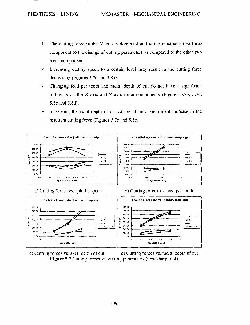
PHD THESIS - LI NINO MCMASTER - MECHANICAL ENGINEERING
>- The cutting force in the Y-axis is dominant and is the most sensitive force
component to the change of cutting parameters as compared to the other two
force components.
>- Increasing cutting speed to a certain level may result In the cutting force
decreasing (Figures 5.7a and 5.8a).
>- Changing feed per tooth and radial depth of cut do not have a significant
influence on the X-axis and Z-axis force components (Figures 5.7b, 5.7d,
5.8b and 5.8d).
>- Increasing the axial depth of cut can result In a significant increase In the
resultant cutting force (Figures 5.7c and 5.8c).
Coated baU nose end mill with new sharp edge
700 00 1- -. _:: ~ II :s::;: ~ 400 00 +-~ _-_-,--____ ,...-_----..l
!:::~I ~ 7000 8000 9000 10000 11 000 1 2000 13001)
Splndl. spud (RPM)
__ Fy
-.-Fz
.....-Resultant F
a) Cutting forces vs. spindle speed
Coated ball nose end mill with new sharp edge
700 00
60000 -1---------->1 __ --500 00 -f----------7~---
40000 +----------,.¥--------' 30000 +------"""'"'2'lIF_--------; 20000 +-------::Jt6PII"'------::r----10000 +-_____ -= ..... _-==:E...-__ OOO+-----T----~---~--~
4
Axial DOC (mm)
--Fx
-.-Fy
-;,-Fz ___ R.sukant F
Coated ball nose end mill with new sharp edge
900 00 r-.~.------'-~---' ----'._-'-'" --,-80000 A 70000 -or 60000 ~ 50000 ... 400 00 -1--.-.....-----------30000~-------------------
2;)0 00 t====:J~~::!=== 10000 .-
000 +-------,...------.----------, 000 oO? 010 015
Feed per tooth (mm)
__ F~'
__ Fz
-Resultant F
b) Cutting forces vs. feed per tooth
Coated ball nose end mill with new sharp edge
BOO 00
700 00
600 00
50000
40000
300 00 __ Resunant F
200 00
100 00
000 0 02 04 06 DB
R.dlal DOC (mm)
c) Cutting forces vs. axial depth of cut d) Cutting forces vs. radial depth of cut Figure 5.7 Cutting forces vs. cutting parameters (new sharp tool)
109

PHD THESIS - LI NING MCMASTER - MECHANICAL ENGINEERING
Coated ball nose end mill with 0.1 mm wear Coitted ball nose end mill with 0.1 mm wur
1500 00
1400 00
110000
g 1000 00
E 800 00
(t 600 00
400 00
200 00
000
6000
-'
::::::;:-- --. ___ Fx __ Fy
""'" ___ Fz
---- -Reru<tantF --~
8000 1(J(()() 12000
Splndll spud (RPM)
a) Cutting forces vs. spindle speed
Coated ball nose end mill with 0.1 mm wear
1500 00 ---..
140000 +-------~~ ...... --1;>00 (1Q +---...,..------...r::.."...o~------' r------,
1000 00 +----....-.."...c,~-----
800 00 -l--.-.:..----.tI'~--~------
80000+-----~~------------~
40000 -l----&-._...:::----!!!.-----'
200 00 +--..:...-.,..,c.=_ .... -===t------.; 000-l------~----~----~-~
Axial DOC (mm)
c) Cutting forces vs. axial depth of cut
~ : ~ ....
180000 -.---- .----~--".,.--- ---- --.-- -~---' -
1600 00 +------~-.,"""""'!!!5iiiOoII---140000 +--,---_. -~-..,..~~ ... , ----120000 +--~-:--, ~~_-.e...-..:... ___ ----. 100000 +-~--'----~----80000 +--:..----------600 IY.I +---------__ -----4:J000 +--___ -==*=:::::::t=:::::!L_ 200 00 -l--..:.-4-.....-. ...... _=-=~L-_ ooo+---~--~--~--~--~
002 004 006 008 010 0 12
Feed perlooth (mm)
b) Cutting forces vs. feed per tooth
Coated ball nose end mill with 0.1 mm wear
1600 00
1400 00
1200 00
100000
800 00
800 ()()
400 00
200 00
000
02 04 06 0 B
__ Fy
__ Fz
-Rerul!3nlF
d) Cutting forces vs. radial depth of cut
Figure 5.8 Cutting forces vs. cutting parameters (worn tool, VB=O.10 mm)
The effect of cutting parameters on the new and worn tools is compared and the
results are shown in Figure 5.9. Changing the cutting speed (Figure 5.9a) and the feed per
tooth (Figure 5.9b) has almost the same degree of effect on the new and the worn tools.
However, increasing the axial DOC (Figure 5.9c) and radial DOC (Figure 5.9d) has more
effect on the worn tool than the new tool, especially the axial depth of cut.
110

PHD THESIS - LI NING MCMASTER - MECHANICAL ENGINEERING
1000 ,----' '--"-~---' .~ .. - -.-.. --.--... ,,-.. _". '''-'.-I . .
800 r....:.-'""-~~~.--~-·"~;··---.:...- -"--~-'
600 [~==~~ .. ~~~~~~:=~~ ... ::.~,,~'~ ~OO i 100 l·--··---··--·--"-·<·--·'-··~·" --.-,,--
o L .-._- .-•..
6000 7000 8000 9000 10000110001200013000
Spindle spud (RPMI
-+-N,~w tool
___ WOOl tool
a) Resultant forces vs. spindle speed
Alelal DOC (mml
-+-t4(''Wtool
___ \\10m tool
c) Resultant forces vs. axial depth of cut
~ ~~~ l~2~~---... I .. :',' . ~ 1000 ~.""'~'-'. -~~'-.-:.--'7-":"--~~'.'-"'-"-'
i :: L~~=---:-'" ~OO L_'"_ .... ....;... .. ;..;,.:..: ... ___ :.:.:.~,:....,~..-___ .. __ c,._~ .. " ... _ .....
I . . . .
-+-Uewtool
____ Worn tool
lOO f- ----o l ..... ,-- .. ....:....~- ... -_ .... -._-_ .. -. ---- -',.
o Ol 0.04 0.06 0.08 0.10 012
Fnd p.r tooth (mml
b) Resultant forces vs. feed per tooth
1600 ! -
g :::: t--;z: .. ----~= j 1000 f'" -".- _ ... " .,,---,.---.. ---.. ' -,---.0. -. .. --
'i 800 t--'-7:-:--~~-.. -~-~ .. ~--. 1 ::: t~-:::~~:~
o L. . o 01 04 0.6 08
Radial DOC (mm)
-+-Newtool
___ WOOl tool
d) Resultant forces vs. radial depth of cut
Figure 5.9 Comparison of the effect of cutting parameters on new and worn tools
From the geometries of the chips (Figure 5.10), we can see that the axial DOC,
radial DOC and feed per tooth control the defonned geometry of the chips.
111
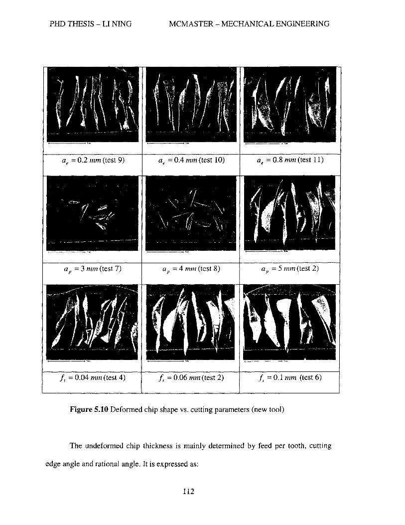
PHD THESIS - LI NING MCMASTER - MECHANICAL ENGINEERING
It = 0.04 mm (test 4) It = 0.06 mm (test 2) 1/ = 0.1 mln (test 6)
Figure 5.10 Deformed chip shape vs. cutting parameters (new tool)
The un deformed chip thickness is mainly determined by feed per tooth, cutting
edge angle and rational angle. It is expressed as:
112

PHD THESIS - LI NING MCMASTER - MECHANICAL ENGINEERING
tc = /, . sin K . sin B
where K represents the cutting edge angle and e is the rotational angle. When the axial
depth of cut is equal to the radius of the cutting tool, K is in the range of 0 to 90°. The
range of the rotational angle e depends on the cutting edge engaging range with the
workpiece. When both the axial and radial DOC equal the radius of the tool, the
maximum un deformed chip thickness is equal to the feed per tooth.
The radial DOC and feed per tooth determine the cusp height of the machined
surface. Increasing these two parameters result in an increase in surface roughness. For
the purpose of increasing productivity and maintaining minimum increase of the cutting
force, the first parameter that can be considered is cutting velocity, followed by feed per
tooth and radial depth of cut.
By observing the color of the chips, it is found that when the tool is sharp
increasing the cutting speed slightly changes the color of the chips. However, from the
color of the chips generated by the worn tool, it is clear that increasing the cutting speed
results in a large increase in cutting temperature. Therefore, tool wear plays a major role
in determining cutting temperature.
By observing the shape of the chips, it is found that cutting velocity does not
significantly influence the shape of the chips while changing the values of axial depth of
cut, radial depth of cut and feed per tooth obviously changes the shapes of the chips
(Figure 5.10). Based on the chip shapes from the preliminary tests, one can see that the
following parameters are suitable for the investigation of chip fonnation, chip color, chip
shape and chip undersurface.
113

PHD THESIS - LI NINO MCMASTER - MECHANICAL ENGINEERING
y Axial depth of cut = 5.0 mm;
» Radial depth of cut = 0.4 - 0.8 mm;
» Feed per tooth = 0.06 - 0.1 mm
The cutting conditions used for the coating testing are summarized in Table 5.4.
Table 5.4 Cutting conditions
Solid ball end mill (substrate) Tungsten carbide, C-2MB from Mitsubishi
Diameter ( D ) tOmm
Number of cutting edges (n ) Two flutes
Workpiece material Hardened HI3 die/mold steel at HRC
48-50, HRC 55-57
Maximum cutting speed (V, max ) 220m/min (7000RPM), 300m/min,
400m/min, 500m/min
Axial depth of cut ( a p ) 5mm
Feed per tooth (It) 0.06 mm/tooth
Stepover distance ( Q e ) O.6mm
Runout <6 Jlm
Overhang length (mm) Around 31 mm
Type of milling operation Down milling
Lubricant Dry cut with lOOpsi compressive air blast
114

PHD THESIS - LI NING MCMASTER - MECHANICAL ENGINEERING
5.4 Deposition of Nano-multilayered PVD Coatings
As described in chapter 2, cathodic arc evaporation is a widely used coating
process with a high deposition rate and a high degree of ionization of evaporated species.
But the target materials need to have electro-conductivity and materials with a too high or
too Jow of a melting point or poor mechanical strength cannot be used. However with the
sputtering process which has a very low ionization ratio, various materials, which are
hard to use in the arc process, are able to be deposited. In order to improve the ionization
rate, the Unbalanced Magnetron Sputtering (UBM) and High Power Impulse Magnetron
Sputtering (HIPIMS) technologies have been introduced. These technologies allow for
more complex coatings both in terms of composition and structure. These coatings are
currently under development to improve tool performance and new coating techniques
have also emerged to deposit complex and high quality coatings. Combining arc and
magnetron processes in a hybrid coater is a way to achieve this goal.
Nano-scale multilayered coatings in this research were deposited by Kobe Steel
Ltd. using a new hybrid coating process that combines cathodic arc and unbalanced
magnetron sputtering [Yamamoto, et aI., 2005]. A plasma-enhanced arc source
[Yamamoto, et al. 2003] and a UBM source were installed in a chamber. Ti2SA16SCrIO
manufactured by a powder metallurgical process was used as a target for the arc cathode
while tungsten, boron carbon, niobium, etc. depending on the type of coatings, was used
for a sputtering target. Tungsten carbide ball-nose end mills were heated up to about
500 °C and cleaned through an Ar ion etching process. Ar-N2 mixture gas was fed to the
chamber at a pressure of 2.7 Pa with a N2 partial pressure of 1.3 Pa. The arc source was
115

PHD THESIS - LI NING MCMASTER - MECHANICAL ENGINEERING
operated at 100 Amps for a 100 mm diameter target. The sputter source was operated
simultaneously with the arc source and the input power to the sputter source was varied
from 0 to 2.5 KW (for a 160 mm diameter target). The substrates were mounted on a
rotating sample holder and passed in front of the arc and the sputter source alternatively
during the deposition. The basic rotation speed of the substrate holder was 5 rpm and it
was tuned up to 7 rpm and 10 rpm for investigating the effect of outer layer thickness on
coating perfonnance. The substrate bias was fixed to 30 V for all depositions. Figure 5.11
shows the cross-sectional Transmission Electron Microscopy (TEM) image highlighting
the nano-scale multilayered nature of the coating. Because of the difference in the
deposition rate of each evaporation source, the layers deposited by arc are thicker than
the ones by the DBM. For instance, in TiAICrN/WN coating (Figure 5.11), the period of
layer cycle is approximately 17 nm. The WN layers are the darker layers due to the
heavier atomic mass of tungsten.
Figure 5.11 Cross-sectional TEM image of nano-multilayered TiAICrNIWN coating.
Parameters of deposition: arc source - 100A; Bias voltage - 30 V; Input DC
power to the UBM source - 1.0 KW. Coating contains 10 at.% of W.
116

PHD THESIS - LI NINO MCMASTER - MECHANICAL ENGINEERING
5.5 Friction Coefficient Measurement
Surface lubricity tests were performed on a specially designed apparatus as shown
in Figure 5.12. To characterize a coating, ideally, a laboratory test should aim to simulate
the contact conditions as closely as possible. This apparatus was designed to mimic an
intensive adhesive interaction at the tool-chip interface. The coefficient of friction
between the coating material and the workpiece material versus temperature was
determined with the aid of this specially designed apparatus.
A rotating sample of the coated substrate (#2 - rotational pin with the diameter of
5 mm and the length of 30 mm) was placed between two polished specimens (#1 - disks
of diameter 25 mm and thickness 5 mm) made of hardened die steel H 13 (hardness HRC
55-57). To simulate tool friction conditions, the specimens were heated by resistive
heating to temperature ranging from 20 to 10aaoe. A standard force of 2400 N was
applied to generate plastic strain in the contact zone. With this setup the moment of
plastic strain initiation could be observed on the surface of the polished samples. The
torque was measured. The corresponding rotating pin made a spherical imprint. After
measuring the size of the imprint, the shearing force can be determined and subsequently
normal stress and shearing stress are obtained. The coefficient of friction was determined
as the ratio of the shearing stress induced by adhesive bonds between the tool and the
workpiece and the normal contact stress developed on the contact surface at different
measuring temperatures. No less than three tests were performed for each kind of coating.
The scatter of the friction parameter measurements was found to be around 5%.
117
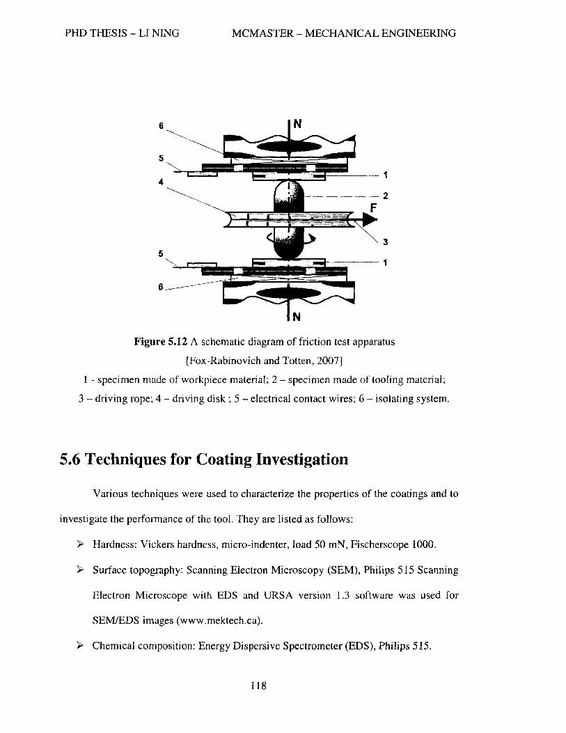
PHD THESIS - LI NING MCMASTER - MECHANICAL ENGINEERING
6
5
4 ~~~1
5
6
------2
3
~':::I---- 1
Figure 5.12 A schematic diagram of friction test apparatus
[Fox-Rabinovich and Totten, 2007]
1 - specimen made of workpiece material; 2 - specimen made of tooling material;
3 - driving rope; 4 - driving disk; 5 - electrical contact wires; 6 - isolating system.
5.6 Techniques for Coating Investigation
Various techniques were used to characterize the properties of the coatings and to
investigate the perfonnance of the tool. They are listed as follows:
~ Hardness: Vickers hardness, micro-indenter, load 50 mN, Fischerscope 1000.
~ Surface topography: Scanning Electron Microscopy (SEM), Philips 515 Scanning
Electron Microscope with EDS and URSA version 1.3 software was used for
SEMIEDS images (www.mektech.ca).
» Chemical composition: Energy Dispersive Spectrometer (EDS), Philips 515.
118
PHD THESIS - LI NINO MCMASTER - MECHANICAL ENGINEERING
>- Microstructure: Transmission Electron Microscope (TEM) used to study total
thickness of the coating, layer thickness, multilayer period (lEOL 2010F
Scanning Transmission Electron Microscope with EDS).
~ Oxidation stability: a furnace (model No.: TL-20 from The Pottery Supply House)
was used for interrupted oxidation test.
~ Micrograph of surface morphology (grain size, grain boundary, texture, and
fracture), element detection, wear mechanisms, chip shape, etc.: Scanning
Electron MicroscopelEnergy Dispersive Spectrometer (SEMJEDS) are mainly
used.
~ Detection of oxides: X-ray Photoelectron Spectroscopy (XPS) , VG ESCALAB
MK2 spectrometer, is used to detect the oxides [aImed during the wear process.
~ Crystal structure and chemical composition: X-ray diffraction (XRD) is a
versatile, non-destructive technique that reveals detailed information about the
chemical composition and crystallographic structure.
~ Friction coefficient: a specially designed apparatus is used to mimic an intensi ve
adhesive interaction at the workpiece/coated cutting tool interface (Figure 5.12).
~ Chip cross-section samples are prepared for analysis of microstructure,
microhardness, chip type and chip fonnation mechanisms. Preparation of chip
cross-section samples has following steps: mounting the chips by using the clay
and epoxy resin, then polishing and etching the samples. The samples are kept in
a sealed jar to avoid oxidation.
119

PHD THESIS - LI NING MCMASTER - MECHANICAL ENGINEERING
Chapter 6
Results and Discussions
The coatings developed and tested in this research are for application in dry hard
high performance machining. The research goal is to achieve high productivity, high
quality and long tool life. In order to reach the goal, nano-multilayered self-adaptive PVD
coatings were developed. These coatings were selected due to their advantages
associated with their nano-structure and self-adaptibiIity properties as discussed in
Chapter 3 and Chapter 4. TiAICrN is considered as the base layer while the transient
elements such as W, Ta, Cr, Nb and some other element such as B are considered for the
thinner lubricious layer. The alternating TiAICrN base layers and lubricous layers are
deposited by alternating Unbalanced Magnetron Sputtering (UBM) and High Power
Impulse Magnetron Sputtering (HIPIMS) to form a 3 micron overall thickness nano
mu1tilayered coating. During this study, the content ratio of the chemical elements in the
thicker TiAICrN base layer is optimized; the phenomena of the developed nano
mul,tilayered coatings under elevated temperatures are revealed~ tool life, tool wear, wear
mechanisms, chip fonnations, cutting forces and cutting temperatures are discussed in
this chapter. The coatings developed in this research are compared with some
commercially available nano-structured coatings as well.
120

PHD THESIS - LI NING MCMASTER - MECHANICAL ENGINEERING
6.1 Optimization of the TiAICrN Base Layer
The purpose of tuning the TiAICrN composition is to obtain an optimal
composition specifically suited for dry high speed machining applications. In fact, four
aspects need to be considered:
~ The lattice structure of the coatings should stay with fcc structure of TiN;
>- High aluminum content to form protective AI-O which serves a protective
function for the tool;
>- Certain amount of Cr to form Cr-O which is lubricious;
~ Ti-O (rutile) should be avoided since rutile is not protective and it can
oxidize very fast.
The varying chemical compositions and the corresponding crystal structures are
listed in Table 6.1. It was found that the crystal structure of the first three coatings (Table
6.1) still stays with fcc structure of TiN. In order to keep the TiN fcc structure, 20% of Cr
is needed when the content of Al is 70%. This is the well-known coating composition
Ti1OAhoCr20N. The composition, ThoAhoCrlON, was not taken into account because its
crystal structure turned to a hexagonal cubic structure which is known to not provide the
desired mechanical properties.
It was found that too much Cr results in the formation of excessive amount of Cr
a tribo-films, which are not as protective as AI-O tribo-films. However, Cr-O oxides are
lubricious. Therefore, a small amount of Cr-O films and a larger amount of protective Al
a films are preferred.
121

PHD THESIS - LI NING MCMASTER - MECHANICAL ENGINEERING
The testing results (Figure 6.1) showed that the composition, TizsA16sCr1ON, gave
the best tool performance and hence was selected as the base layer for nano-multilayered
coatings. Figure 6.2 shows the SEM images of the cutting edge, the flank face and the
notch area when the tools reached the end of tool life. For the remained of this thesis,
ThsA16SCrlON will be simplified as TiAICrN.
Table 6.1 Chemical composition of the base layer
No. Coatings (chemical composition) Crystal structure
1 Tilol\I6sCr2SN FCC
2 TilOA170Cr20N FCC
3 Ti25Al6SCrloN FCC
4 Ti 2oA17oCrl oN HCP
I Comparison of TiAICrN monolayer coatings
600
- .... ~ 500
I 0 ... .. .!::! 400 E r I ........ Ti25A165CrlON
I -~ 300
~ ... J ___ Ti 10A170Cr20N
IV
! 200 J ...... Ti 10Al65Cr25N c L// «S u: 100 of. ~. ~ - ... . "" o ,..
0 20 40 60
Linear cutting length (m)
Figure 6.1 Tool life of TiAICrN monolayer coatings (Vc = 300 mlmin,)
122

PHD THESIS - LI NING
Ti25A165Cr 1 ON
(cutting length 52.7 m)
MCMASTER - MECHANICAL ENGINEERING
Ti 10Al70Cr20N
(cutting length 39.2 m)
a) SEM images of the cutting edge
c) SEM images of notch area
Ti10Al65Cr25N
(cutting length 31.1 m)
Figure 6.2 SEM images of three base coatings at the end of tool life (C-2MB)
123

PHD THESIS - LI NING MCMASTER - MECHANICAL ENGINEERING
6.2 Nano-multilayered TiAICrNIBCN Coatings
BCN was chosen as the lubricious layer due to its good tribologicaJ properties.
The deposition process and parameters are described in chapter 5. Three coatings were
deposited at different rotational speeds of the substrate holder. They were 1.5 RPM, 5
RPM and 10 RPM so that the layer cyclic period changed. Cutting tests were performed
at the cutting speed of 220 mlmin. The other cutting parameters are listed in Table 5.4.
After the cutting length of 30 meters, it was shown that TiAICrNIBCN (10 RPM) had the
lowest flank wear among the three TiAICrNIBCN coatings but its performance was not
better than the monolayer coating TiAICrN (Figure 6.3). Moreover, coating spallation
was observed on three TiAICrNIBCN coated worn tools (Figure 6.4). However, the
smooth undersides of the chips were observed possibly due to the formation of low
friction lubricous boron oxides. It was found that the melting point of boron oxide is
lower than the cutting temperature estimated by the color of the generated chips so that
boron oxides could not stay as a solid lubricant during the cutting process and will be
squeezed out due to the high contact pressures. Also the liquid lubricant would
eventually run out due to the limited supply of boron near the surface of the coating.
124

PHD THESIS - LI NING MCMASTER - MECHANICAL ENGINEERING
0.06
E 0.05 's004 ~ . ~ 0.03
~ 0.02 u: 0.01
TiAlCrNIBCN coatings
O----~----~----~--~----~--~~--~
1
o 5 10 15 20 25 30 35
Cutting length (m)
1--- 1.5 RPM --tr 5 RPM ""'*- 1 0 RPM -+- TiAlCrN I
Figure 6.3 Tool wear curves of TiAICrNIBCN coatings
o-~·-~ .. . ,.,.- .
. . ,,-"'~
~-
c) Rake face (10 RPM) d) Flank face (10 RPM)
Figure 6.4 SEM images of the worn tools at cutting length of 30 m
125

PHD THESIS - LI NING MCMASTER - MECHANICAL ENGINEERING
6.3 Nano-multilayered TiAICrNIWN Coatings
Based on the results and observations of the TiAICrNIBCN coated tools, it was
predicted that solid lubricants should be beneficial for a cutting tool to achieve good
perfonnance under the conditions of dry hard high speed machining. Therefore, WN was
selected as the second candidate of the lubricious layer because of the low coefficient of
friction and the higher melting point of W -0. Three TiAICrNIWN coatings were
deposited by altering the power of the sputtering source from 0.5 kW, 1.0 kW to 1.5 kW
so that the thickness of the lubricious layer increased as the source power increased. After
the cutting length of 30 meters, it was not possible to identify the difference of these three
coatings due to their similar perfonnance and the flank faces were only worn around 18
microns but it was obvious that they all performed better than the TiAICrN monolayer
coating and as expected much better than the TiAICrNIBCN coatings. In order to identify
the difference, the cutting test was continued to 250 meters and then it was clearly shown
that the one deposited using the 1.0 kW sputtering source had the lowest tool wear. The
compositions and properties of the TiAICrN monolayer coating and TiAICrNIWN nano
multilayered coatings are listed in Table 6.2. Figure 6.5 shows the flank wear of the
TiAICrN and TiAICrNIWN (1.0 kW) coatings vs. cutting length at the cutting velocity of
220 mlmin. From this figure one can see that the tool coated with TiAICrNIWN (1.0 kW)
coating only has half of the wear as compared to the one with the TiAICrN coating.
126

PHD THESIS - LI NING MCMASTER - MECHANICAL ENGINEERING
Table 6.2 Composition and properties of TiAICrN and TiAICrNIWN coatings
Coating composition, at. % (EDX data) Properties of the coatings
Weight gain, Flank wear Input power Micro mglcm2 after 250 ill
to the hardness Elastic after I-hour cutting sputtering (HVO.05) Modulus oxidation in air (J.!m)
source (kW) Al Ti Cr W (OPa) (GPa) at 900°C
0 60.29 28.69 11.02 0 34.4 577 0.046 76
0.5 56.59 27.71 10.58 5.11 34.14 547 0.109 69
1.0 53.68 27.57 9.22 9.53 33.94 512 0.078 40
1.5 47.68 23.98 9.24 19.09 29.97 452 0.092 47
80
70 -+-TiAICrN
-.-TtAICrNIWN 60
E -= 50 to. i 40
~ 30 ca u::
20
10
0
0 50 100 150 200 250 300
Linear cutting length (m)
Figure 6.5 Tool wear of TiAICrN and TiAICrNIWN coatings vs. cutting length
127
PHD THESIS - LI NINO MCMASTER - MECHANICAL ENGINEERING
The reason for the better performance of TiAICrNIWN coating is related to the
phenomenon of seizure which was described in Chapter 4. Seizure is a typical process in
cutting operations. This is explained in Trent and Wright [2000]. In general the
phenomenon of seizure controls the cutting tool wear behaviour and leads to an
extremely short tool life. However, with nano-scale multi-layered TiCrAINfWN coating
there is very low seizure intensity on the flank and rake surfaces of a worn end mill
(Figures 6.6, 6.7 and 6.17). SEM elemental mapping shows that it could be probably
explained by the fonnation of protective alumina tribo-films on both the flank (Figure
6.6) and rake surfaces of the tool (Figure 6.7). The W -0 tribo-films usually fonn on the
rake surface (Figure 6.7) of the end mills with a TiAICrNIWN coating. It is most likely
that the non-protective rutile films or AI-Ti-O films are also present on the surface.
128

PHD THESIS - LI NING MCMASTER - MECHANICAL ENGINEERING
10 J.lm II( )It
Figure 6.6 SEM image and EDX elemental maps of the worn flank surface of ball
end mill with TiAICrNIWN PVD coating
129

PHD THESIS - LI NING MCMASTER - MECHANICAL ENGINEERING
Figure 6.7 SEM image and EDX elemental maps of the worn rake surface of ball
end mill with TiAICrNIWN PVD coating
130

PHD THESIS - LI NING MCMASTER - MECHANICAL ENGINEERING
Figure 6.S shows the intensive photoelectron lines on the electron spectrum for Ti,
Al and W. After the curve fitting of the main components, it is possible to identify the
nature of the tri bo-films formed on the worn end mill surface. Calculations performed on
the presented data show that around 60% of Ti, 50% of Al and 60% of W has been
transformed into the tribo-oxide layers during cutting within the surface layer of the
TiAICrNIWN coating. The ability of the tungsten nitride nano-Iayer to form tribo-oxide
seems to be superior to other metallic components of the coating (Figure 6.S). In contrast
to the wear beh~viour of a TilOAhoCr20N coating studied earlier [Fox-Rabinovich, et a1.,
2005], chromium tribo-oxides were not found on the worn surface of the TiAICrNIWN
coated tools (Figure 6.S).
The known aluminium oxides are gamma-alumina, theta-alumina and alpha
alumina. Gamma- and theta-alumina are two metastable phases of aluminum oxide
existing at temperature approximately below 700°C while alpha-alumina is a stable phase,
formed/converted from the metastable phases at higher temperature. Ab03, has high
melting point of 2054°C. It is insoluble in water and very slightly soluble in strong acids
and alkalies. Gamma alumina is composed of minute colorless cubic crystals with
specific gravity about 3.6. Alpha alumina is composed of colorless hexagonal crystals
with specific gravity about 4.0. And sapphire belongs to alpha-alumina. During the
cutting process with cutting temperature above SOO°C to I 100°C, the stable alpha
alumina was fanned on the tool rake and flank surfaces.
131
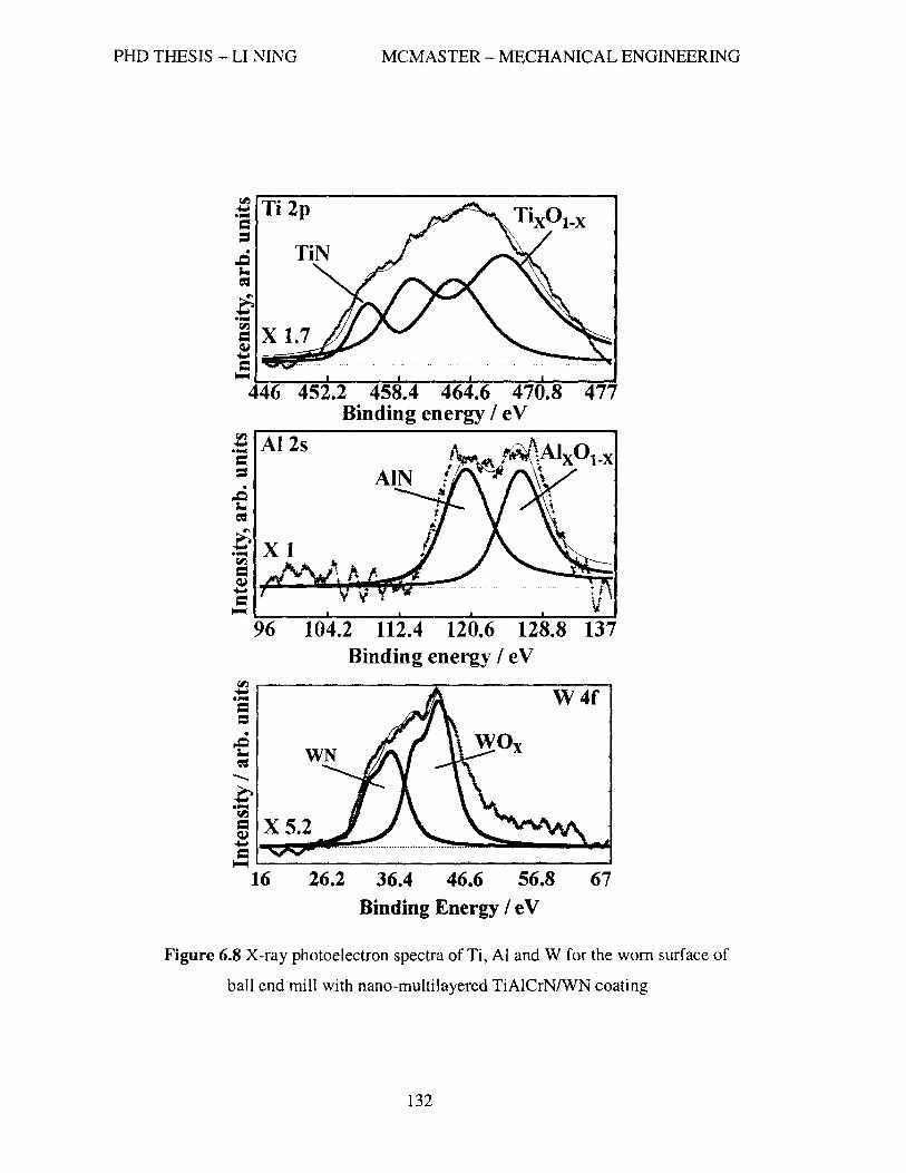
PHD THESIS - LI NINO
! Al2s = = ~ = :6 .~ X 1 rI'l =
MCMASTER - MECHANICAL ENGINEERING
~ .~--~~~~~~~
= ~~----~----~----~----~----~ 96 120.6 128.8 Binding energy I eV
~~------------~----------VV--4-f~
= = ~ ~
-... ~ .~
(I)
5 X 5.2 ..... I~~ .. ~~· = ~~--------------------------~
16 26.2 36.4 46.6 56.8 67 Binding Energy / e V
Figure 6.8 X-ray photoelectron spectra of Ti, Al and W for the worn surface of
ball end mill with nano-multilayered TiAICrNIWN coating
132

PHD THESIS - LI NINO MCMASTER - MECHANICAL ENGINEERING
Significant structure transformation of the initial nano-multilayered structure of the
TiAICrNIWN coating has taking place during cutting (Figure 6.9). The microstructure of
the worn cutting tool surface with the TiAICrN/WN coating within an island-like seizure
of the workpiece material was studied using TEM. Electron diffraction spots had been
identified in the electron diffraction patterns of three zones. Zone A in Figure 6.9 presents
a near-perfect (110) Fe (bcc) structure of the workpiece material (tool steel HI3); Zone B
shows a cubic WN structure; Zone C indicates the presence of a nano-crystalline structure
of a TiAICrN layer remote from the surface. Figure 6.9 shows that the initial nano-
mulitilayered structure was destroyed within a thin superficial layer of the coating due to
heavy loads and high temperatures generating at the tool/workpiece interface under
severe conditions of dry high performance machining.
Figure 6.9 TEM images of the worn surface of ball end mill with TiAICrNIWN coating with diffraction patterns A- (1 IO)Fe (bee); B-cubic WN; C-nano-crystalline structure of
TiAICrN (fcc)
133

PHD THESIS - LI NING MCMASTER - MECHANICAL ENGINEERING
6.4 Comparison of Nano-structured Coatings
For the purpose of comparison, five different PVD coatings, including three well
known commercially available coatings: nano-composite AITiN/SbN4, nano-crystalline
A167Ti33N and mono-layered Ti1OAhoCr20N, and two experimental nano-multilayered
coatings: Ti2SA16SCrlONIBCN and TbsAI6sCrIONIWN, were tested. The properties of
these coatings are listed in Table 6.3.
Table 6.3 The properties of commercial and experimental coatings
[Fox-Rabinovich &Totten, chapter 9, 10, 2006]
Micro hardness
Coating Structure (HVO.05) (GPa)
Al67Tb3N Nano-crystalline grain size 10-25 nm 30
AITiN/ShN4 Nano-composites, grain size 5-10nm 45
lli]oA17oCr2oN Nano-crystalline grain size 10-25 nm 34.5
Ti2sAl65CrloNI\\TN Nano-multilayer, 17nm/period 34
Ti2SAI65CriONIBCN Nano-multilayer, 17nm/period 34
Figure 6.1 0 shows the coefficients of friction for the investigated coatings under
the temperature range from 20 to 1000°C. The results show that the TiAICrNIWN
coating can maintain a very low coefficient of friction (0.06-0.08) over a wide range of
temperature from 150 to 1000°C; the TiAICrN coating also exhibits a relatively low
coefficient of friction in a range of 0.086-0.01 over the same temperatures; the
lliAICrNIBCN coating has a low coefficient of friction (0.1) within the range of 150 to
450°C; the coefficient of friction of the AITiN coating gradually increases from 0.13 to
134

PHD THESIS - LI NING MCMASTER - MECHANICAL ENGINEERING
0.25 as the temperature rises; and the AITiN/SbN4 coating starts with a high coefficient
of friction 0.34 and then the coefficient of friction decreases as the temperature rises, at
600°C, the coating reaches its lowest coefficient of friction 0.14 and then increases up to
0.35 as the temperature rises up to 1000°C.
0.400
0.350
c 0.300 0
n 'i: 0.250 -'0 .... 0.200 c CP U 0.150 5: CP 0 0.100 ()
0.050
0.000
0 200 400 600 800
Temperature (Oe)
1000 1200
...... AITiN/Si3N4
-'-AITiN
-e-TiAICrN
---TiAICrNIWN
-..-TiAICrN/BCN
Figure 6.10 Friction coefficients of nano-structured coatings
Figure 6.11 shows the flank wear of the five coated ball nose end mills. Over a
cutting length of 30 meters the nano-composite TiAIN/Si3N4 coating had the maximum
tool wear followed by the nano-crystalline AITiN coating, nano-multilayered
TiAICrNIBCN coating and mono-layered TiAICrN coating, while the nano-multilayered
TiAICrNIWN coating had the lowest tool wear, which was approximately half that
observed for the other coatings. The maximum resultant cutting forces were calculated
from the measured forces and are shown in Figure 6.12. Similar to the trend of flank wear
135

PHD THESIS - LI NING MCMASTER - MECHANICAL ENGINEERING
shown in Figure 6.11, the tool with the TiAINISbN4 coating generated the highest cutting
force while the one with the TiAICrNIWN coating had the lowest cutting force.
0.05 --r--------------------~--__,
0.04 +----------------"""-;;~-----'"---;
o------~~----~------~------~----~----~
o 5 10 15 20 25 30
Unear cutting length (m)
1-.-TiAICrN/BeN --4- AITif\VSi3N4 -*- A1TiN --- TiAICrN - TiAlCrNlWN I Figure 6.11 Tool wear curves of nano-structured coatings
(Dry machining AISI HI3 using solid ball end mill of 10 mm with the coatings shown in the
Figure at the cutting parameters: cutting velocity 220 m1min, axial depth of cut 5 mm, radial
depth of cut 0.6 mm and feed per tooth 0.06 mm)
136

PHD THESIS - LI NING MCMASTER - MECHANICAL ENGINEERING
6oo.00~-------------------------------------------~
~ 500.00
8 .E 400.00
C 19 :; 300.00
! E ::s 200.00 E
-= :::e 100.00
0.00
AIliNlSi3N4 AlliN TiAICrN TiAICrNlBCN TiAICrNlWN
Hard coatings
Figure 6.12 Maximum resultant forces of nano-structured coatings
Chips were collected during machining at various cutting lengths and Figure 6.13
shows the typical shapes of the collected chips at cutting lengths of 1 meter and 30
meters. Chips from the new, unworn coated tools have very similar shapes. Figure 6.13e
shows the curliest chips generated by the TiAICrNIWN coated sharp mill. After the tools
cut 30 meters an obvious difference in chip shape was observed. The chips corresponding
to the nano-composite AITiN/ShN4 coating (Figure 6.13a) and the nano-crystalline
AITiN coating (Figure 6.13b) were almost flat, with little curl, while the chips
corresponding to the TiAICrNIBCN coating (Figure 6.13d) and the TiAICrNIWN coating
(Figure 6.13f) showed significantly more curl. The chips from the TiAICrN coating
(Figure 6.13c) were in between in tenn of the degree of curl. Among these samples the
chips from TiAICrNIWN coating exhibited the highest degree of curl.
137

PHD THESIS - LI NINO MCMASTER - MECHANICAL ENGINEERING
(a) AJTiNISi3N4 (30 m) (b) AITiN (30 m)
(c) TiAICrN (30 m) (d) TiAICrNIBCN (30 m)
(e) TiAICrNIWN (l m) (f) TiAICrNIWN (30 m)
Figure 6.13 SEM images of chip shape
138

PHD THESIS - LI NING MCMASTER - MECHANICAL ENGINEERING
Presently there is no reliable way to measure the cutting temperature precisely
during a ball nose end miJIing process. Thus the cutting temperatures were estimated
based on the relation (cutting temperature vs. chip color) presented by Venkatesh, et a1.
(1993) and Ning, et al. (2001) (Table 6.4). The relation between the color of the chips
and the estimated temperatures for this study is shown in Table 6.5. It was observed that
the chip color generated by the new coated tools were an a similar shade of light brown.
After cutting 30 meters, the chips from the TiAICrNIBCN and the TiAICrNIWN coated
tools changed to a golden brown shade while the ones from the AITiN/SbN4 and AITiN
coated tools became purple and brittle. From Table 6.5, we can see that after cutting 30
meters the cutting temperature increased only a little for the TiAICrNIWN and
TiAICrNIBCN coatings while it increases by approximately 100°C for the AITiNIShN4
and AITiN coatings.
In order to identify the effect of the compressed air blast on the color of the chips,
trial tests on the TiAICrN coated tool with and without an air blast of 0.69 MPa (l00 psi)
were performed (Table 6.6). It was found that the color of the chips without the air blast
was brown and purple while the one with the compressed air blast was light brown. The
difference induced by the compressed air was approximately 80-100°C based on this
color comparison approach.
139

PHD THESIS - LI NING MCMASTER - MECHANICAL ENGINEERING
Table 6.4 Chip temperature vs. chip color
Chip temperature vs. chip color [Venkatesh et al., 1993]
Chip temperature vs. chip color [Ning, et al., 2001]
Chip temperature (OC) Chip color Chip color Chip temperature caC)
829 Light brown Light brown 800-840 881 Golden brown Brown 820-880 900 Dark brown+bJ ue Blue+brown 860-920 937 Light blue Blue+purple 920-960 981 Dark blue Dark blue 960-1000
Dark blue+greei> 1000
Table 6.5 Chi£ color vs. chiE temEerature Chip
Cutting length temperature Coatin~ (m) Cuttin~ condition Chi£ color (C)
All coatings 1 0.69 MPa air blast Light brown 800-840 TiAICrN 30 0.69 MPa air blast Dark brown 880-900
AITiN/Si3N4 30 0.69 MPa air blast Purple 920-960 AITiN 30 0.69 MPa air blast Purple 920-960
TiAICrNIBN 30 0.69 MPa air blast Golden brown 840-880 TiAICrNIWN 30 0.69 MPa air blast Golden brown 840-880
Table 6.6 Chip color vs. chip temperature with/without air blow Chip temperature
Coating Cutting length (m) Cutting condition Chip color (OC) TiAICrN 1 Without air blow Brown+purple 900-920 TiAICrN 1 0.69 MPa air blast Light brown 800-840
The results from the SEM and the EDX analysis of the surfaces of the worn ball
nose end mills are shown in Figures 6.14 to 6.17. Significantly different wear behaviors
can be observed for different coatings. For example, a zone of intensive seizure was
observed on the surface of a cutting tool with the nano-composite AITiNISi3N4 coating
(Figure 6.14). Severe spallation of the coating layer on the tool with the TiAlCrNIBCN
coating (Figure 6.15) was also seen. The cutting tool with the TiAICrN coating (Figure
140

PHD THESIS - LI NING MCMASTER - MECHANICAL ENGINEERING
6.16) had a much higher rate of workpiece material pick-up than the tool with the
TiAICrNIWN coating (Figure 6.17) but was less intensive when compared to the nano-
composite AITiNISbN4 coating. Among all the tools the worn surface of the
TiAICrNIWN coated cutting edge had the lowest seizure intensity.
Pick up of the workpiece material
10 1<.\
Figure 6.14 SEM image and EDX spectrum of flank face of ball end mill with AITiN/ShN4 coating
141

PHD THESIS - LI NING MCMASTER - MECHANICAL ENGINEERING
Slight pick-up of workpiece material
Ti Fe
!
Ti Coating layer --=1------1' spallation
AI
ko\ 10
Figure 6.15 SEM image and EDX spectrum of flank face of ball end mill with TiA1CrNIBCN coating
Pick-up of workpiece material
Al
Fe ~
~.\I 10
Figure 6.16 SEM image and EDX spectrum of flank face of ball end mill with TiAICrN coating
142

-- ~-- -- --------- ~~--
PHD THESIS - LI NING MCMASTER - MECHANICAL ENGINEERING
FS-195
Ti Slight pick- , up of workpiece material
Fe
Cr 60 Al
10
Figure 6.17 SEM image and EDX spectrum of flank face of ball end mill with TiAICrNIWN coating
kaV
The results presented above highlight the importance of the lubrication properties
of the coating and show the role that lubricity plays in dry high speed machining.
During the cutting operation chips are generated by a shearing action as a part of
creating the final desired machined surfaces. In ball end milling the cutting velocity at the
tool tip is zero and increases along the cutting edge to the depth of cut. The chip flow
velocity increases from the tool tip to the depth of cut. Curly chips are typical of this
cutting operation. Also there is friction at the tool-chip interface due to the pressure and
the motion of the chip along the rake face. If the friction is high, the tool contact side of
the chip can undergo further plastic deformation in the secondary shear zone after the
plastic defonnation on the shear plane of the primary shear zone. Since the chip flow
faces large resistance due to high friction, chips become less curled and thicker with a
corresponding increase in contact length. This friction has a significant influence on the
cutting forces, temperature rise and the shape of the chip.
143

PHD THESIS - LI NING MCMASTER - MECHANICAL ENGINEERING
It is well known that alumina has excellent heat and oxidation resistance and a
much lower thermal conductivity than the layer of nitride coating, cemented carbide tool
substrate and the workpiece material such as AISI HI3 [Fox-Rabinovich and Totten,
2006]. Therefore, it insulates the tool surface from the heat generated during chip
formation and redirects the heat flow towards the chip. Alumina is also very hard and
dense and its oxidation stability can be maintained up to I200°C [Fox-Rabinovich and
Totten, 2006]. Thus the thin film of alumina serves to protect the substrate material
against abrasive wear, oxidation wear and crater wear [Fox-Rabinovich and Totten,
2006]. That is why all of the coatings studied in this paper are based on TiAIN-based
coatings rich in aluminum.
The results show that the nano-multilayered TiAICrNIBCN coating performed
worse than the TiAICrNfWN coating under dry high speed machining conditions. Boron
oxide tribo-films are supposed to be fanned under these conditions as a result of tribo
oxidation and it is known that boron oxides are good lubricants [Erdemir, 2000].
However, the melting point of boron oxide is low, typically 450°C [Erdemir, 2000]. Once
the boron oxide forms at the tool surface it transforms to a liquid phase under the high
cutting temperatures (see table 6.5) and then it is squeezed out of the cutting zone by the
heavy forces acting on the frictional surface. It is also known that the onset oxidation
temperature of boron oxides is about BOO°C [Fox-Rabinovich and Totten, 2006] and the
coated tool most probably loses its oxidation stability above this temperature. Figure 6.15
shows the phenomenon that one coating layer is peeled off revealing the next layer.
Based on this mechanism these cutting edges are not protected to the same degree and
144

-~- ~-- ~-- ---------
PHD THESIS - LI NING MCMASTER - MECHANICAL ENGINEERING
thus lose their strength and fail much faster than with the other nano-multilayerd
coatings.
The main reasons for the poorer perfonnance of the nano-composite AITiN/ShN4
coating and nano-crystalline AITiN coating in this study as compared to the nano
multilayered TiAICrNIWN coating are their higher coefficient of friction values and the
resulting poorer lubricity in the cutting zone (Figure 6.10). High friction in these cases
results in intensi ve seizure in the tool-chip interface as the chips flow over the tool
(Figure 6.14). Therefore, in addition to their hardness and oxidation resistance, the
friction characteristics of the hard coatings should be optimized.
However, tool life and wear behavior could be improved if the self-lubricating
properties of the coatings at elevated temperatures can be enhanced. A good example
here is the TiAICrN/WN nano-multilayered coating.
It is found that the nano-multilayered TiAICrN/WN coating is able to generate
tungsten oxides due to the tribo-oxidation process (Figure 6.8). During the running in
stage, a certain amount of local sticking of workpiece material to the coated tool surface
enhances the formation of the W oxide tribo-films (Figure 6.7). This sticking of
workpiece material to the tool surface leads to intensive heat generation [Trent and
Wright, 2000; Ning, et aL, 2001] and rapidly transforms tungsten from the WN nano
layer closest to the top friction surface and fonns the oxide tribo-film (Figure 6.8).
Tungsten oxide has a high melting temperature around 1500°C and it has low shear
strength [Erdemir, 2000] so it is present at the cutting tool/workpiece interface as a solid
145

PHD THESIS - LI NING MCMASTER - MECHANICAL ENGINEERING
high temperature lubricant. In addition, tungsten oxide is able to retain a relatively high
hardness of around 15-22 GPa at elevated temperatures [Endemir, 2000].
The formation of the tungsten tribo-oxides during the running-in stage prepares an
excellent working environment in the cutting zone for the post-running-in stage.
Therefore, both intensity of seizure and the coefficient of friction values drop (Figures
6.17, 6.10), decreasing the cutting forces (Figure 6.12) and heat generation at the
tool/workpiece interface (Table 6.5), which ultimately results in the overall wear intensity
reduction (Figure 6.5). In synergy with the other tribo-oxides (in this case alumina) that
are fonning during the friction of TiAICrN nano-Iayers (Figure 6.8), this fonnation of a
lubricious tungsten oxide leads to a significant tool life increase. By combining this data
with tool life data found in Figure 6.5 one can conclude that the lubricious/protective
tribo-oxide films predominantly isolate the workpiece from the cutting tool surface.
Surface damaging wear mechanisms such as seizure become close to the external wear
with critically lower wear intensity. That is why dry machining of the hardened H13 steel
becomes quite efficient if the nano-multilayered TiAICrNIWN coating is applied onto the
cutting tool surface.
The nano-multilayered structure of the coatings plays a significant role in the
improvement of wear behaviour. It is possible that the nano-scale multilayered structure
critically enhances two beneficial phenomena: 1) mass transfer at the start of the running
in stage that results in quick generation of tribo-oxides with the suitable composition and
microstructure; 2) selective oxidation within the island-like seizure zones with the further
146

PHD THESIS - LI NING MCMASTER - MECHANICAL ENGINEERING
formation of tribo-oxides that critically reduce the intensity of this surface damaging
process, resulting in tool life improvement.
Thus the self-adaptive, synergistically alloyed, nano-multilayered coatings are
promising materials for severe tribo-applications associated with high temperature and
stress. Metallurgical design of coatings used for severe applications should be based on
the understanding of the synergistic action during friction of alloying elements that are
present in nano-multilayered coatings. The direction of research that deals with the
complexity of friction, including in-depth understanding of the self-organization process
and the improvement of hard coatings based on this phenomenon, should be considered
as a significant trend for future development of wear resistant coatings.
The study of chip cross-section was performed. The results, shown in Figure 6.18,
demonstrate that the microstructure of the chips strongly depends on the type of coating
applied. The chips generated by the ball end mill with A1o.65 Tio.35N nano-crystalline
coating has a very wide hardening zone (Figure 6.18a), which corresponds to the
estimated temperature presented in Table 6.5. The chips formed by the tool with
Alo.65 Tio.35N/Si3N4 nano-composite coating have a narrower hardening zone as compared
to the one on the chips by A1o.65 Tio.35N coated too. Further observations show that no
intensive flow zone but micro-cracks exist on the chips, which indicates that the chips are
quite brittle due to high cutting temperature (Figure 6.18b). In contrast, the chips
generated by the self-adaptive TiAICrNIWN coating has a very narrow hardening zone
and a flow zone with intensive plastic deformation (Figure 6.18c), which indicates lower
147

PHD THESIS - LI NINO MCMASTER - MECHANICAL ENGINEERING
friction and lower cutting temperature as compared to the other two categories of
coatings above.
a) b)
c)
Figure 6.18 SEM images of chip cross-sections. a) chips generated by Alo.65 Tio.35N
coated tool; b) chips by the Alo.65Tio.35N/SbN4 tool; c) the chips generated by the self
adapti ve TiAICrNIWN coating.
148

PHD THESIS - LI NING MCMASTER - MECHANICAL ENGINEERING
The microhardness measurements were also performed on the chip cross-section
versus the distance from the chip undersurface (Figure 6.19). The results show that
intensive hardening of the workpiece material occurs when nano-composite
A1o.65 Tio.35N/SbN4 coating or nano-crystalline A1o.65 Tio.3sN coating is applied. In
contrast, an effect of chip softening takes place when self-adaptive TiAICrNIWN coating
is applied. The phase composition was analyzed by performing Roentgen analysis. The
results show that a mixture of retained austenite and martensite formed on the
undersutface of the chips generated by the tool with A1o.65 Tio.35N coating. There is a
minor amount of the retained austenite on the chips formed by the Alo.65Tio.35N/ShN4
coated tool while no austenite was found on the chip surface from the self-adaptive
TiAICrNIWN coating (Table 6.7). These results further confirm the self-adaptability of
TiAICrNIWN and its functions on the reduction of friction and cutting temperature.
149

PHD THESIS - LI NING MCMASTER - MECHANICAL ENGINEERING
750
700 10 ""'" 0 650 ~ ,;
600 CI)
Go> C 'C 550 ... ! 0 ... 500 u ~
450
400 0
Distance from tooVchip interface (micron)
I : Nano-composite AITINlSi3N4 coatings
___ Self-Adapti\€ nano-scale multi-layered liAICrN+WN coating
--fr- Nano-crystalline AlliN coating
Figure 6.19 Microhardness of the chips vs. the distance from tool/chip interface
Table 6.7 Phase composition on the chips undersurface (X-ray Diffraction (XRD) data).
Coating Phase composition of the chips
undersurface
N ano-crystalline AITiN a+y (some amount)
Nano-composite AITiN/Si3N4 a+y (traces)
Self-adaptive TiAICrN/WN a only
150

PHD THESIS - LI NING MCMASTER - MECHANICAL ENGINEERING
6.5 Nano-multilayered TiAICrN/MexN Coatings
The results from the investigation of TiAICrNIBCN and TiAICrNIWN coatings
give the following conclusions:
1. The formation of tribo-oxides working as solid lubricants (W-O) during
cutting greatly improve the performance of the cutting tool.
2. The formation of the liquid lubricating films (B-O) is not beneficial under the
aggressive cutting conditions used in this study.
3. Under the dry hard high performance machining at the cutting speed of 220
mlmin, the cutting temperature can go approximately from 850°C to beyond
1000°C. If the cutting speed is increased the cutting temperature will go even
higher.
4. The power to the sputtering source and the rotational speed of the sample
holder are recommended to be set to 1 kW and 5 rpm, respectively.
These guidelines are used for further coating development. For the applications of
higher cutting speeds, more transition metal nitrides of V and VI periods, excluding
Vanadium and Molybdenum, were considered as candidates for investigation. Table 6.8
lists the melting points of the transitional metal oxides and other related oxides from high
to low. In order to obtain solid lubricants during friction, Vanadium and Molybdenum
should be excluded because they belong to the liquid lubricants under the proposed
cutting conditions. Therefore, only the transitional elements such as Ta, Cr, Wand Nb
were considered in nano-multilayered TiAICrNIMexN coatings.
151
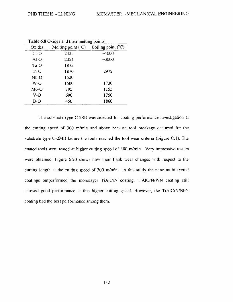
PHD THESIS - LI NING MCMASTER - MECHANICAL ENGINEERING
Table 6.8 Oxides and their melting points Oxides Melting point (oC) Boiling point (oC)
Cr-O 2435 ..... 4000 AI-O 2054 ..... 3000 Ta-O 1872 Ti-O 1870 2972
Nb-O 1520 w-O 1500 1730
Mo-O 795 1155
v-a 690 1750 B-O 450 1860
The substrate type C-2SB was selected for coating performance investigation at
the cutting speed of 300 m1min and above because tool breakage occurred for the
substrate type C-2MB before the tools reached the tool wear criteria (Figure C.l). The
coated tools were tested at higher cutting speed of 300 m1min. Very impressive results
were obtained. Figure 6.20 shows how their flank wear changes with respect to the
cutting length at the cutting speed of 300 m1min. In this study the nano-multilayered
coatings outperfonned the monolayer TiAICrN coating. TiAICrN/WN coating still
showed good performance at this higher cutting speed. However, the TiAICrNlNbN
coating had the best petfonnance among them.
152

PHD THESIS - LI NING MCMASTER - MECHANICAL ENGINEERING
--~--.-------------~--.
600
_ 500 (I)
c: E
oS:! 400 S >< cu ~ 300 >
j 200 oX c: .!! u.. 100
Ball end mill with different coatings
o----------~--------~----------~------~
o 50 100
Cutting length (m)
150 200
-+-liAICrN __ TiAICrNlCrN
-A- TiAICrNlWN
~ TiAICrNfTaN
-e-liAICrNlNbN
Figure 6.20 Tool wear curves of ball end mills coated with TiAICrN based coatings (cutting speed of 300 mlmin)
6.6 The Effect of Contact Length on Tool Performance
It is found that the cutting tool performance depends on not only wear resistance,
the condition of lubricity, hot hardness, and toughness but also on the contact length
between the chip and the tool rake face. As described earlier, if the chip-tool contact area
becomes too large, high frictional force wi1l be generated during cutting and hence high
cutting temperature as well, subsequently, seizure phenomenon becomes more intensive
which eventually results in tool failure. On the contrary, if the chip-tool contact length is
too small, the cutting pressure and cutting temperature are concentrated in a very small
region at the cutting edge. Under this condition, the cutting edge undergoes severe attack
153

PHD THESIS - LI NING MCMASTER - MECHANICAL ENGINEERING
from both force and temperature with the cutting tool failing rapidly. In general the
shorter the chi p-tool contact length, the curlier the chips. Figure 6.21 shows that the tool
with the Ti25Al65CrlON coating generated extremely curly chips (needle-like chips) at the
very beginning of cutting. From the undersurface of the chips (Figure 6.21), it is
observed that the surfaces are quite rough, which indicates that the coefficient of friction
is not low,
Tb5Al65CrION coating, cutting speed 300m/min
Cutting length 1 m Cutting length 30 m
~'~!"'~~.~~
~:~I1!._~!.:l:~.!I"lP.¥ .....
SEM images of chip undersutface
Cutting length 53 m
(the end of tool life)
Figure 6.21 SEM images of chip shapes and undersurfaces (Ti25AI65CrION)
154

PHD THESIS - LI NING MCMASTER - MECHANICAL ENGINEERING
Regarding the TiAICrNlTaN coating, the changes in chip shapes versus cutting
lengths are very interesting (Figure 6.22). At the very beginning, the chip shape is quite
similar to the ones generated by the TiAICrNIWN coated tool machined with a cutting
velocity of 220 mlmin. The contact length corresponding to this type of chip shape seems
optimal. However, as the cutting length increases, the chips become curlier. At the
cutting length of 30 m, the shape of the chips changes to needle-like chips which is just
similar to the ones generated by ThsA16sCrION at the very beginning of the cutting
process. Because of the short contact length, the cutting edges undergo high pressure and
temperature. Therefore, the tool quickly reaches the wear criteria of O.3mm. From SEM
images of the undersurface of the chips, it can be inferred that the tribological property of
the TiAICrNffaN coating against HI3 tool steel is superior to the one for TbsAl6sCrlON
at an elevated temperature.
155

PHD THESIS - LI NING MCMASTER - MECHANICAL ENGINEERING
TiAICrNrraN coating, cutting speed 300m/min
Cutting length 1 m Cutting length 30 m
SEM images of chip undersurface
Cutting length 55 m
(the end of tool life)
Figure 6.22 SEM images of chip shapes and undersurfaces (TiAICrNffaN)
156

PHD THESIS - LI NING MCMASTER - MECHANICAL ENGINEERING
For TiAICrN/CrN coating (Figure 6.23), the undersurfaces of the chips start with
a slightly rough surface. As the cutting length increases the shape of the chips become
less curly and the undersurfaces become coarser, which indicates the high temperature
lubricity properties are not good.
TiAICrN/CrN coating, cutting speed 300m/min
Cutting length 1 m Cutting length 30 m Cutting length 63 m
(the end of tool life)
SEM images of chip undersurface
Figure 6.23 SEM images of chip shapes and undersurfaces (TiAICrN/CrN)
157

PHD THESIS - LI NING MCMASTER - MECHANICAL ENGINEERING
TiAICrN/WN coating (Figure 6.24) also starts with a similar undersurface to the one
of TiAICrN/CrN. However, as the cutting length increases to 30 m, the undersurface is
more smooth than the one generated at the very beginning and the shape of the chips is
still curly but much less curl than the one from a new tool. When the tooJ reached its tool
wear criteria, one can still see quite smooth chip surfaces, which indicate that this coating
has very good high temperature tribological properties.
TiAICrNIWN coating, cutting speed 300m/min
Cutting length 1 m Cutting length 30 m Cutting length 145 m
(the end of tool life)
SEM images of chip undersurface
Figure 6.24 SEM images of chip shapes and undersurfaces (TiAICrNIWN)
158
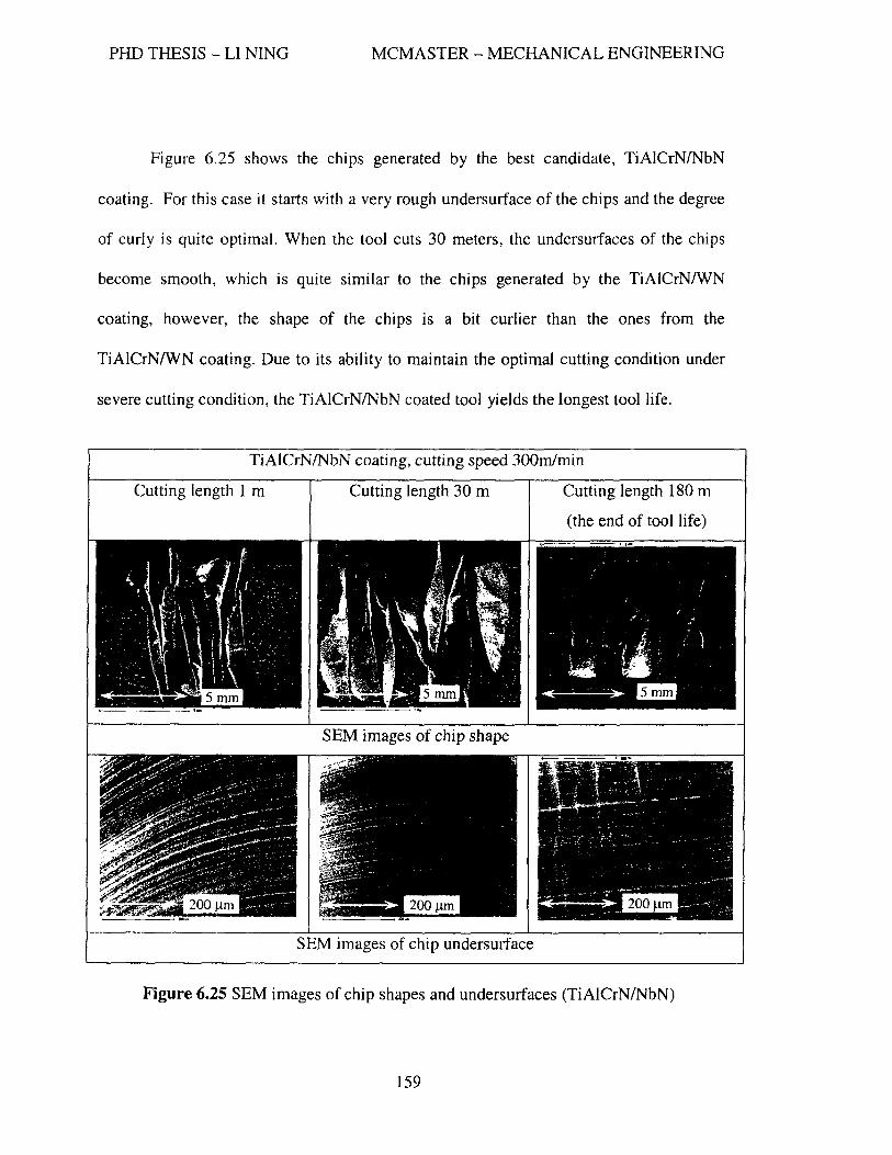
PHD THESIS - LI NING MCMASTER - MECHANICAL ENGINEERING
Figure 6.25 shows the chips generated by the best candidate, TiAICrNlNbN
coating. For this case it starts with a very rough undersurface of the chips and the degree
of curly is quite optima]. When the tool cuts 30 meters, the undersurfaces of the chips
become smooth, which is quite similar to the chips generated by the TiAICrNIWN
coating, however, the shape of the chips is a bit curlier than the ones from the
TiAICrNIWN coating. Due to its ability to maintain the optimal cutting condition under
severe cutting condition, the TiAICrNlNbN coated tool yields the longest tool life.
TiAICrNlNbN coating, cutting speed 300m/min
Cutting length 1 m Cutting length 30 m Cutting length 180 m
(the end of tool life)
SEM images of chip undersurface
Figure 6.25 SEM images of chip shapes and undersurfaces (TiAICrNlNbN)
159

PHD THESIS - LI NING MCMASTER - MECHANICAL ENGINEERING
From observations made on the chips, the following statements can be made:
)0> Tool-chip contact length cannot be too short or too long. A short contact length
causes the cutting pressure and temperature to be concentrated on the cutting edge,
therefore, the cutting edges are prone to premature damage and hence have a short
life. On the contrary, a long contact length results in high friction and hence high
cutting forces and high cutting temperature which also have negative effects on the
perfonnance of the tool.
)0> There is an optimal contact length, the ability to maintain this condition under severe
cutting condition is one of the key factors for a tool to achieve the longest tool life.
)0> The degree of curling and the smoothness of the undersurface of the chips are
associated with conditions of favourable lubricity in the cutting zone.
6.7 Nano-multilayered TiAICrNlNbN Coatings
Since the TiAICrNlNbN coating exhibited the best perfonnance among the
coatings studied, it was chosen for further study. As usual, optimizing the content of Nb
was perfonned.
Like the deposition of TiAICrNIWN coatings, TiAICrNINbN coatings were
deposited on the ball end mills (type C-2SB) by varying the power (0.5 kW, 1.0 kW and
2.5 kW) to the sputtering source. The thickness of the lubricious layer NbN increases as
the power increases from 0.5 kW to 2.5 kW. Table 6.9 lists the composition and
properties of the coatings corresponding to the different powers of the sputter source. The
data in Table 6.9 shows that the sputtering power does not have significant influence on
160

PHD THESIS - LI NINO MCMASTER - MECHANICAL ENGINEERING
the microhardness of the three Nb coatings~ however, it affects the elastic modulus and
oxidation resistance of the coatings. The introduction of NbN layers on the TiAlCrN
base layers results in an increase in coating plasticity and a slight decrease in oxidation
resistance. It was found that the TiAICrNINbN coating, deposited using the sputtering
power of 1.0 kW and having approximately 4 at. % of Nb, has better oxidation resistance
than the other two coatings with about 2 at. % of Nb and 10 at. % of Nb. Without the
addition of NbN, the microhardness of the coating is approximately 35 GPa, while with
the addition of NbN, the microhardness of the three coatings does not vary significantly
with the input of DC power but stays around 31 GPa. However, a slight decrease in
elastic modulus is observed as the content of Nb increases. The oxidation resistance of
the coating has a significant impact on the wear resistance of the cutting tools under high
performance dry machining conditions. Due to the affinity of Nb with oxygen, the short
term oxidation resistance of nano-multilayered TiAICrNINbN coatings is lower
compared to a mono-layered TiAICrN coating.
161
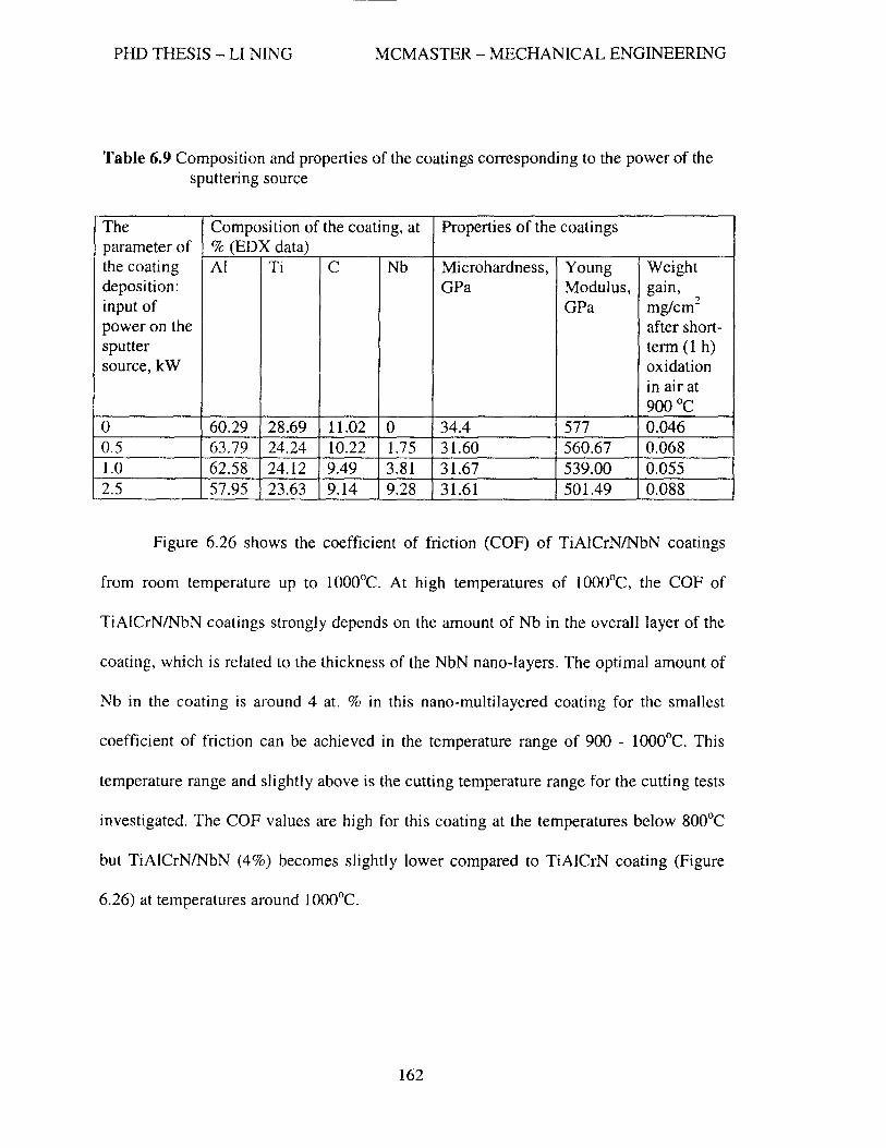
PHD THESIS - LI NINO MCMASTER - MECHANICAL ENGINEERING
Table 6.9 Composition and properties of the coatings corresponding to the power of the sputtering source
The Composition of the coating, at Properties of the coatings parameter of % (EDX data) the coating AI Ti C Nb Microhardness, Young Weight deposition: GPa Modulus, gaIn, input of GPa mg/cm2
power on the after short-sputter term (1 h) source, kW oxidation
in air at 900°C
0 60.29 28.69 11.02 0 34.4 577 0.046 0.5 63.79 24.24 10.22 1.75 31.60 560.67 0.068 1.0 62.58 24.12 9.49 3.81 31.67 539.00 0.055 2.5 57.95 23.63 9.14 9.28 31.61 501.49 0.088
Figure 6.26 shows the coefficient of friction (COF) of TiAICrNINbN coatings
from room temperature up to 1000°C. At high temperatures of lOOO°C, the COF of
TiAICrNINbN coatings strongly depends on the amount of Nb in the overall layer of the
coating, which is related to the thickness of the NbN nano-layers. The optimal amount of
Nb in the coating is around 4 at. % in this nano-multilayered coating for the smallest
coefficient of friction can be achieved in the temperature range of 900 - 1000°C. This
temperature range and slightly above is the cutting temperature range for the cutting tests
investigated. The COF values are high for this coating at the temperatures below 800°C
but TiAICrNINbN (4%) becomes slightly lower compared to TiA]CrN coating (Figure
6.26) at temperatures around 1000°C.
162

I
PHD THESIS - LI NINO
0.18 --.-------j-
c: o
0.16
0.14
~ 0.12 'C :: 0.1 o -j 0.08 ()
~ 0.06 -t------i
o o 0.04 +--------l
0.02 -t------i
-+-TtAICrN
_ TtAICrNb2N
---i!- TtAICrNb4N
~ TiAICrNb10N L..-.---,-------;r--'
MCMASTER - MECHANICAL ENGINEERING
I
L' 0 0 ______ 2_0_0 _____ 4_0_0~ ____ 60_0 _____ 8_0_0 ______ 10_0_0 ______ __ Temperature, oC
1200 j
Figure 6.26 Coefficient of friction of TiAICrNINbN coatings vs. temperature
Figure 6.27 shows the tool life of these three coatings. It is found that the tool life
of the TiAICrN/NbN coatings with varying Nb content corresponds to the COF values at
elevated temperatures. TiAICrNlNbN (10% / 2.5 kW) coating has the worst performance
while TiAICrN/NbN (4% / 1.0 kW) and TiAICrNlNbN (2% 10.5 kW) coatings have very
similar tool life. The longest tool life is achieved by a nano-multi-Iayered TiAICrNINbN
coating with overal1 Nb content of 4 at. %.
163

PHD THESIS - LI NING MCMASTER - MECHANICAL ENGINEERING
---"------ ----------------------,
Tool life ofTiAlCrNlNbN coatings
E 100 :J E
.~ 0 __ ~-----I-----'------'-----'--------J ~
o 50 100 150 200 250
Cutting length (m)
-+- TiAJCrNlNbN (20/0) ~ TiAJCrNlNbN (4%) -.- TiAlCrNlNbN (10%)
Figure 6.27 Tool life with different TiAlCrNINbN coatings deposited on C-2SB
(cutting speed: 300 mlrnin)
In order to compare how well the coatings protect the cutting tools, all three
TiAICrNINbN coated tools were taken out for SEM study at the cutting length of 100 m.
Figure 6.28 shows the SEM images of the cutting edge, flank face, notch area and rake
face. Comparing these three coatings, one can see that the value of the maximum flank
wear has no big difference at a cutting length of 100 m (Figure 6.27). However, the SEM
images reveal a bigger difference (Figure 6.28). For instance, obvious cutting edge
micro-chipping can be observed on the cutting edge of the TiAICrNINbN (10%) coated
tool. Comparing TiAICrNINbN (2%) and TiAlCrNlNbN (4%), very similar wear pattern
can be observed in the notch area (Figure 6.28c); however, the average flank wear of the
TiAICrNlNbN (4%) coated tool is narrower than the one of the TiAICrNINbN (2%)
coated tool (Figure 6.28b). Therefore, TiAICrNlNbN (4% / 1.0 kW) coating was selected
for further wear progression study.
164

PHD THESIS - LI NING MCMASTER - MECHANICAL ENGINEERING
0.5 kW 1.0 kW 2.0kW
Figure 6.28 Comparison of three TiAICrNlNbN coatings at the cutting length of 100 m
165

PHD THESIS - LI NING MCMASTER - MECHANICAL ENGINEERING
6.8 Wear Progression Study of TiAICrNINbN Coating
Since the novel nano-multilayered TiAICrNINbN (4 at. % I 1.0 kW) was the best
coating, it was used to perform comprehensive investigation of the wear behavior, reveal
the progression of the wear process and chip formation, and present suggestions for
extending the performance of the machining process. The coating was deposited on the
same ultra-fine grained cemented carbide ball nose end mill (C-2SB, 10 mm diameter).
The too] was tested by dry machining of hardened steel AISI HI3 (HRC 55-57) at the
higher cutting speed of 300 mlrnin. In order to track the tool wear progression SEM and
EDX studies were intermittently performed. During the cutting process, the chips were
collected, and the flank wear and the corresponding force components were measured.
Based on the measured force components, the maximum average forces were computed
and a matrix with tool wear and corresponding force components at different cutting
lengths was formed. Figure 6.29 demonstrates the changes of the maximum cutting forces
during the tool life for the TiA1CrNINbN coated tool. The two force components Fy (the
direction of radial depth of cut) and Fz (the direction of axial depth of cut) increase at
very low rates until the cutting length reaches 165 m and show a very similar trend to the
corresponding wear curve for this tool (Figure 6.27). While in the feed direction, the
cutting force component Fx shows a slight drop in the middle range of tool service life.
This is not uncommon as a machining process is very complex and there are many factors
which affect cutting forces in addition to tool wear such as cutting zone temperature
which can vary with wear substantially. Furthermore, factors interact with each other and
dominate at different stages during cutting. For example the drop in Fx might be due to
166

PHD THESIS - LI NING MCMASTER - MECHANICAL ENGINEERING
the improvement of lubricity in the cutting zone because of the formation of the
protective oxides. When the increase of cutting force component due to tool wear is less
than the decrease of force by the improvement of lubricity, the force component drops.
Table 6.10 lists the correlation of wear to the cutting forces and the percentage of force
increment. One can see that the Fy (direction of radial depth of cut) and the Fz (direction
of axial depth of cut) are highly correlated to flank wear. Therefore, Fy and Fz are
recommended for monitoring the cutting tool.
Average maximum forces
2500~------------------------------------~
Z 2000+-----------~----------~----~--~~~ -UJ
8 1500+-----~--------~--------~----~~---4 ... o -
0+---------r---------~------~~------_4
o 50 100
Cutting length (m)
150 200
-+-Fx
-+-Fy
-.-Fz ~Fr
Figure 6.29 Cutting forces vs. cutting length (TiAICrN/NbN (4%))
T bl 610 C l' a e . orre atlon 0 f wear WIt cuttIng f orces an d h t e percentage 0 ff orce Increase Vbmax Fx(max) Fy(max) Fz(max) Fr(max)
(Jlm) (N) (N) (N) (N)
Cutting length 0.2 m 10 456.18 568.81 292.72 728.81
Cutting length 200 m 292 845.21 1889.49 1169.43 2022.03
Percentage of force increment - 85% 232% 299% -
Correlation to wear - 0.64 0.94 0.95 -
167

PHD THESIS - LI NING MCMASTER - MECHANICAL ENGINEERING
6.8.1 Tool wear and wear mechanisms
The tool wear progression on the rake and flank faces of the ball end mill from the
new to the worn tool is exhibited in Figure 6.30. Figure 6.30a shows how the new tool
surfaces look. In this case a droplet phase of different size could be observed on the
surfaces (Figure 6.30a). Based on the study of the worn surfaces of the cutting tools by
means of EDX analysis, five wear zones were identified. They are: worn coating region,
exposed substrate material, crater wear zone, seizure zone and build-up area, as shown in
Figures 6.28b-e.
It was found that very small areas of substrate were exposed at the very cutting
edge after a short cutting distance of 3.9 m (Figure 6.30b). As the cutting length
increased the coating was wearing out and the substrate material was exposed more
intensively. Therefore, the exposed substrate zone was getting wider which lead to
intensive to01lchip interaction and temperature growth (Table 6.11). This process had a
gradual character. TiAICrNlNbN coating showed excellent protective ability up to the
length of cut around 150 m. Up to this length of cut no evidence of intensive interaction
at the tool/chip interface was found and the wear rate was relatively low (Figures 6.28a-c
and 6.25). When the exposed area of the substrate material at the cutting edge became
wider, the cutting temperature became higher due to the interaction between the non
protected cutting edge and the chip during friction (Table 6.11). As the temperature
increased above 10000 e the coating lost its protective ability and intensive seizure could
be observed on both the flank and rake faces (Figure 6.30d-e). As the exposed substrate
area became wider, two zones in this area were formed: 1) worn substrate zone which
168

PHD THESIS - LI NING MCMASTER - MECHANICAL ENGINEERING
was formed as a result of rubbing and sliding by chips (Figure 6.30d); 2) crater zone,
which was caused by diffusion as the chips moved through the rake face under high
temperatures (Figure 6.30d). At the same time seizure zones were formed on the rake
and flank faces of the tool as a result of the workpiece material adhering to the tool
surfaces during chip formation (Figures 6.28d and 6.28e). At the initial stages of wear
one could barely see a seizure zone (Figure 6.30b) because the tooI/chip contact length
was quite short (chips were curly, Figure 6.34a). Once the tool became dull, the cutting
temperature and cutting forces became higher, the contact length grew (chips became
less curly (Figures 6.31 b-f) and consequently, the seizure zones in both the flank and
rake faces became wider (Figures 6.28d and 6.28e). The built-up zones were composed
of workpiece material, substrate material and coating elements, and they were located in
the flank/worn coating band interface and rake/worn coating band interface. The built-up
zone formed due to workpiece material rubbing along the cutting edge, carrying some
substrate and coating materials which then stuck to the cutting zone during chip
formation (Figures 6.28b-c).
169

PHD THESIS - LI NING MCMASTER - MECHANICAL ENGINEERING
a) TiAICrNlNbN new cutting edge
b) TiAICrNINbN 3.9 m cutting length
Substrate
'A
c) TiAICrNINbN 100 m cutting length
170
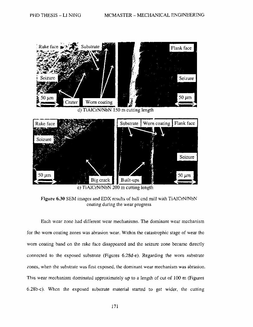
PHD THESIS - LI NING MCMASTER - MECHANICAL ENGINEERING
Worn coating
d) TiAICrNINbN 150 m cutting length
Figure 6.30 SEM images and EDX results of ball end mill with TiAICrNINbN coating during the wear progress
Each wear zone had different wear mechanisms. The dominant wear mechanism
for the worn coating zones was abrasion wear. Within the catastrophic stage of wear the
worn coating band on the rake face disappeared and the seizure zone became directly
connected to the exposed substrate (Figures 6.28d-e). Regarding the worn substrate
zones, when the substrate was first exposed, the dominant wear mechanism was abrasion.
This wear mechanism dominated approximately up to a length of cut of 100 m (Figures
6.28b-c). When the exposed substrate material started to get wider, the cutting
171

PHD THESIS - LI NING MCMASTER - MECHANICAL ENGINEERING
temperature became higher and hence chemical (diffusion) wear became dominant and
the craters were formed on the rake face (Figure 6.30d). The zones of build-up were
related to the seizure, and wear mechanisms such as adhesive, abrasion as well as
diffusion. Seizure intensified after the cutting length of 150m due to temperature growth
(Figures 6.28d-e). As the cutting temperature and stress increased, a parallel to the
cutting edge crack of more than 50 Jlm appeared within the exposed substrate zone.
6.8.2 The formation of tribo-films
To understand the mechanism of adaptability and confirm the formation of tribo
films of nano-multilayered TiAICrNINbN coating, a photoelectron spectrum (XPS) study
on the worn tool surfaces and an elemental mapping analysis by SEMlEDX were carried
out.
Figure 6.31 shows the photoelectron spectra from the rake face of a
TiAICrNINbN coated worn ball end milL The interpretation of the spectra was made
based on complex investigation of the changes in the intensity at the positions of Ti 2p,
Al 2p, Cr 2p and Nb 3d lines for the coating after wear. It was found that intensive tribo
oxidation took place on the surface of the hard coating within the wear zone. All the
metallic elements of the coating were oxidized during friction under high temperatures
and the corresponding tribo-oxides were formed such as Ti-O, AI-O, Cr-O and Nb-O.
Tribo-oxidizing intensity was different for each metallic component in the complex
nitrides. As shown in Figure 6.31a, the titanium in the complex nitrides transform to Ti02
rutile, and its quantity is 62.0% in comparison to Ti in nitride (38.0%). Figure 6.31 b
172

PHD THESIS - LI NING MCMASTER - MECHANICAL ENGINEERING
shows that 70.0% of Al in nitride was transformed to an Ah03 sapphire-like phase. The
Al 2p line binding energy for tribo-oxide has a higher binding energy than corresponding
equilibrium nitride or alpha and gamma-Ah03 phases (73.9 e V). The AI oxide binding
energy for these tribo-films is higher (74.8 eV; Figure 6.31b), and this value is very close
to what corresponds to sapphire. This data corresponds to previously published data on
sapphire-like tribo-films formations during high perfonnance cutting.
Figure 6.31c presents XPS spectra of Cr-O-based tribo-oxide films. The
chromium is oxidized when forming of 28.0% Cr+3 and 39.0% Cr+4 oxides. These films
have some lubricious properties and could improve wear behavior acting in synergy with
protective alumina-based films. The intensity of tribo- oxidation of Nb is very high
(Figure 6.31d) at high cutting temperatures. Two types of Nb-O tribo-films are formed as
a result of tribo-oxidation during cutting, i.e., 45.0% of NbO and 28.00/0 of Nb20 s. In
summary, the tribo-films, formed during cutting process, consist of protective sapphire
like tribo-oxides (Figure 6.31b) with some amount of non-protective rutile-like oxides
(Figure 6.31a) and polyvalent lubricious tribo-oxides of Cr (Figure 6.31c) and Nb
(Figures 6.29d).
173

PHD THESIS - LI NING MCMASTER - MECHANICAL ENGINEERING
li02 457.8 eV
liAINx 455.8 eV
Binding energy. eV
a) Ti 2p photoelectron spectra
569 572 575 578 581 584 587 590 Binding energy, eV
c) Cr 2p photoelectron spectra
en -'§ AITiNx ..Q 73.9 eV
AI2p
AI203 (sapphire)
"ca
~ .U; c S .E
7
68 70 72 74 76 78 80 82 84 Binding energy, eV
b) AI 2p photoelectron spectra
Nb3d
195 201 207 213 219 Binding energy, eV
d) Nb 3d photoelectron spectra
Figure 6.31 XPS of the worn surface of the TiAICrN/NbN coated tool
It is noticed that for conditions of high-performance machining, the Nb-based
oxide tribo-films could significantly enhance wear resistance at elevated temperatures.
The formed oxides have high thermal stability due to the presence of strong inter-atomic
bonds in a compound with a heavy atomic nucleus. Therefore, the TiAICrNINbN coating
is able to perform its protective functions on the cutting tool.
One more reason for the tool life improvement of the TiAICrNINbN coated
cutting tool is the abi1ity of Nb-O tribo-films to dissipate energy during friction at
174

PHD THESIS - LI NING MCMASTER - MECHANICAL ENGINEERING
elevated temperatures. It is known from the literature that one of the features of Nb-based
oxides is their high electro conductivity at high temperatures (Table 6.11) compared to
other tribo-oxides such as alumina, rutile and Cr-based tribo-oxides. This property is
consistent with metallic materials which then indicates that it could work as a solid
lubricant and possess an increased ability to dissipate energy during friction. This is an
important property for an interrupted cutting process like ball end milling.
Table 6.11 Specific electro-resistance (SER) of different oxides vs. temperature [Crist,
2000; Samsonov (Ed.), 1976]
Oxide Temperature, DC Specific electro-resistance (SER), Ohm'm
Ah0 3 800 3.5x1Oo
1000 5xl04
1100 104
Ti02 800 1.2xl0L
1200 8.5xl0L
Cr203 800 78 1000 40 1488 21.3
W03 800 2x10J
Nb20 5 1200 8x10-" 1500 2.8x10-J
To further support this hypothesis, High Resolution Electron Energy Loss
Spectroscopy (HREELS) analysis of the worn surface of the cutting tools with
TiAICrNlNbN coating was perfonned. Figure 6.32 shows the HREELS spectra from the
worn surface of the TiAICrNlNbN coated cutting tool and it presents the high intensity of
plasmon peaks. The plasmon peak intensity in the spectrum of primary electrons energy
loss is related to the excitation of collective oscillations among free electrons and
detennined by their concentration [Kovalev and Wainstein, 2006]. High intensity peaks
175

PHD THESIS - LI NING MCMASTER - MECHANICAL ENGINEERING
(Pl-P4 in Figure 6.32) on the spectra of the coating, which are observed at the surface of
the oxide tribo-films (ionic compounds [Patscheider et aI, 2001; Halleck, 1986]), indicate
the existence of metallic bonds [Fox-Rabinovich, et al., 2006]. A surface with metallic
bonds has a higher ability to dissipate energy during friction because the mobility of the
dislocations is probably enhanced within the surface layer of the oxide tribo-films with
high intensity of plasmon peaks [Fox-Rabinovich, et aI., 2006]. The generation of
dislocation with higher mobility could ensure stress relaxation within the friction zone
and reduce the formation of an excessive amount of defects on the surface. This will
prevent the surface energy from growing, reduce the intensity of surface damage and
hence results in an overall lower wear rate.
(/) ...... . -s::: ::l . .c s.. m
~ .-(/) s::: G.l ...... s::: -
0.66 1.0 Loss energy, eV
Figure 6.32 HREEL spectra of the worn surface of the TiAICrNINbN coated tool
176

PHD THESIS - LI NING MCMASTER - MECHANICAL ENGINEERING
An elemental mapping technique is also used to reveal the distribution of oxides
on the rake and flank faces of the worn tool. Figures 6.31 and 6.32 present the elemental
mapping images. The results show that intensive tribo-oxidation on both surfaces took
place with the formation of two major types of oxides: the protective oxides (niobium
oxide, alumina and chromium oxide) and the non-protective oxide (rutile). The
protective oxide tribo-film formation is extremely beneficial to dry high speed machining
conditions. It results in very low intensity seizures occurring in the flank and rake faces
up to the cutting length of 150 m (Figures 6.28b-c). However, when the cutting
temperature started to be higher than 1100°C, intensive oxidation occurred with the
formation of non-protective oxides (rutile) (Figures 6.31-6.32). Therefore, the coating
lost its protective ability and intensive seizure developed (Figure 6.30d-e).
177

PHD THESIS - LI NING MCMASTER - MECHANICAL ENGINEERING
( ) 200um ( ) 200um
Figure 6.33 Element mapping of flank face ball end mill with TiAICrNINbN coating at the cutting length of 200m
178

PHD THESIS - LI NING MCMASTER - MECHANICAL ENGINEERING
( ) 1 00 urn 100 urn Figure 6.34 Element mapping of rake face of ball end mill with TiAICrNINbN coating at
the cutting length of 200m
179

PHD THESIS - LI NINO MCMASTER - MECHANICAL ENGINEERING
6.8.3 Chip formation
Figure 6.35 shows the progress of the chip shapes and chip undersurfaces with the
length of cut. Curly chips and smooth undersurface of the chips were observed at the
initial stage of wear (Figure 6.35a). In this situation, the major mode of chip flow was
sliding. After the cutting of 30 meters, the shape of the chips started to become quite flat
and the chip underside became wavy (Figure 6.35b) as compared to the ones generated
by the new tool. In this case, the major modes of chip flow became sliding and sticking.
The chips were caught by the rake face and released due to large shearing force. In
addition, the un-deformed chip thickness was very small (0.06 mm). Therefore, a wavy
chip surface was formed. As the cutting length grew, the shape of the chips had no
significant change; however, rough "ears" on the underside of the chips were formed
(Figures 6.33c-e). As the tool wear increased, the cutting edge became dull and more
ploughing action instead of cutting was involved in the cutting process. This resulted in a
large number and big size of "ears" (Figure 6.35e). During chip formation there were
three phenomena involved. The first one was material strain hardening due to the large
plastic deformation of the chip material. The second was thermal softening due to high
cutting temperature. The third one was the quenching effect of the chip by the
compressive air blast under the intennittent cutting operation. The quenching took place
when the actual temperature at the tool/chip interface was above the temperatures of
austenization for H 13 tool steel. As a result, very hard and brittle chips were formed with
the structure that consisted of un-tempered martensite and retained austenite. At different
wear stages, the dominant phenomenon changed. As the tool became worn, the combined
180

PHD THESIS - LI NING MCMASTER - MECHANICAL ENGINEERING
effect of the strain hardening and quenching resu1ted in brittle chips. Therefore, a large
number of cracks were fanned (Figures 6.33c-e).
-oE-----i ..... 200 J-lm
length of 30 m
2 mm .. 200 /lm
c) At the cutting length of 100 m
181

PHD THESIS - LI NING MCMASTER - MECHANICAL ENGINEERING
.... ----llt. 200 Jlffi
length of 150 m
-4---""""i.... 200 Jlm e) At the cutting length of 200 m
Figure 6.35 SEM images of chip shapes and surfaces (TiAICrNINbN)
The SEM images of the chip cross-sections are presented in Figure 6.36. Again,
curly (Figure 6.36a), flat (Figure 6.36b) and wavy chips (Figures 6.34c-d) and brittle
chips (Figure 6.36e) were observed from the low magnification images corresponding to
the cutting lengths of 0.5, 30, 60, 100 and 150m. Based on the higher magnification
images, continuous chip fonnation was observed at the cutting length of 0.5 m (Figure
6.36a). As the tool gradually got worn the regular saw-tooth chips for hard machining
were formed which are shown in Figures 6.34b-e. It was also found that as the tool wear
increased, the chip segmentation frequency decreased and the plastic defonnations in the
182

PHD THESIS - LI NING MCMASTER - MECHANICAL ENGINEERING
primary shear zone became larger and larger and the crack propagation from the free
surface close to the tool tip got deeper and deeper (Figures 6.34b-e).
a) At cutting length of 0.5 m
b) At cutting length of 30 m
c) At cutting length of 60 m
183

PHD THESIS - LI NINO MCMASTER - MECHANICAL ENGINEERING
d) At cutting length of 100 m
e) At cutting length of 150 m
Figure 6.36 SEM images of chip cross-section at different cutting lengths (TiAICrNlNbN)
Figure 6.37 is the typical saw-tooth chip cross-section that was obtained from this
study. Four zones were observed, i.e, 1- white layer zone due to phase transformation
from the quenching phenomenon, 2- deformation zone (underside of the chip at the
secondary shear zone) due to friction~ 3 - shear plane/zone due to the primary shearing,
4-less defonned zone due to saw-tooth chip formation. Again, this result further confirms
the combined effect of the strain hardening, thermal softening and quenching during the
chip fonnation. From the SEM images with high magnification (Figure 6.38), it was
184
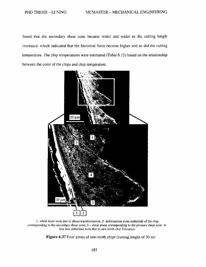
PHD THESIS - LI NINO MCMASTER - MECHANICAL ENGINEERING
found that the secondary shear zone became wider and wider as the cutting length
increased, which indicated that the frictional force became higher and so did the cutting
temperature. The chip temperatures were estimated (Table 6.12) based on the relationship
between the color of the chips and chip temperature.
1- white layer zone due to phase transformation; 2- deformation zone underside of the chip corresponding to the secondary shear zone; 3 - shear plane corresponding to the primary shear zone 4-
less less deformed zone due to saw-tooth chip formation
Figure 6.37 Four zones of saw-tooth chips (cutting length of 30 m)
185

PHD THESIS - LI NINO MCMASTER - MECHANICAL ENGINEERING
a) 4m b)60m c) 150 m
Figure 6.38 SEM images of chip cross-sections (1- secondary shear zones)
Table 6.12 Chip color vs. chip temperature (TiAICrNlNbN (4 at. %)
Cutting lenKth (m) Color of chips Estimated temperature (OC) 0.5 Brownish purple 860 - 920 30 Blue + pUiPle + brown 900-960 60 Blue + green + purple 960-1020 100 Green + blue + purple >1000 150 Green + si I ver >1100 200 Green + silver + radish >1100
brown (brittle chips)
Coating efficiently protects the rake and flank surfaces of the cutting tool and
prevents interaction with the workpiece material through the formation of tribo-films.
However, a relatively small area around the cutting edge (within a range of 30-50
microns) controls the wear rate of the cutting tool due to the high concentration of stress
and high temperature generation within this area during friction. Thus the wear resistance
of the coated tool depends on both substrate material and the coating applied. To sustain
intensi ve heat generation at the cutting edge the coating has to be able to perfonn
protective functions at temperatures above 1000oC.
186

PHD THESIS - LI NINO MCMASTER - MECHANICAL ENGINEERING
6.9 Improvement in Productivity
The potential capability of the TiAICrNlNbN coating for further improvement of
productivity was tested at cutting speeds of 300 mlmin, 350 mlmin and 400 mlmin, and
the tool life curves are shown in Figure 6.39. Figure 6.40 shows that the cutting lengths
can be completed at the cutting speed from 300 mlmin to 400 mlmin when the tool wear
criterion is set to be 0.25 mm. It can be seen that even when the cutting speed goes up to
400 mlmin, the tool life can still maintain 62.5% of the one at the cutting speed of 300
m1min.
As discussed previously, the cutting tools with the TiAICrNlNbN coating can
sustain wear resistance under extremely aggressive cutting conditions. This is attributed
to the synergistic action of the oxides formed during cutting.
400
350 +--------/-+-300 m/min f--------+------+-Y-----I
___ 350 m/min
300 en
+--------1--6-400 m/min f--------+------+-_____.----I
c g 250 --~~- --~--~----+-
E ~ 200 Z ;: .!I: 150 I:: ftI u::
100 ---------- -~--- ------;:;;;;.~~,.,...
50
0 0 50 100 150 200 250
Length of cut. m
Figure 6.39 Tool life curves of the coated tools with TiAICrNlNbN coating
187

PHD THESIS - LI NINO MCMASTER - MECHANICAL ENGINEERING
220~-------------------------------------.
200+-~~------------------------------~
a. ~E 180+-------~~------------------------~ r! E G.I&t)
i~ 160+---------------~~----------------~ EO
il 140+-------------------------~--~----~ '0 i 120+-----------------------------------~ c Go!
~ 100~----------------~----------------~ 300 350 400
Cutting speed, mlmln
Figure 6.40 Cutting lengths vs. cutting speeds when flank wear is 0.25 mm
The material removal rate (MRR) for milling is calculated by:
MRR == 12' f' . N . a . a J t P e
where n is the number of teeth, !, is the feed per tooth, N is the spindle speed, a p is the
axial depth of cut and ae is the radial depth of cut.
Table 6.13 lists the calculated material removal rate corresponding to the cutting
speed. It can be seen that the material removal rate is significantly increased with the
application of the advanced self-adaptive coating TiAICrNINbN.
Table 6.13 Material removal rate vs. cutting speed
Cutting speed 220 300 350 400
(m/min)
Material removal rate 2520 3439 4013 4586
(mm3/min)
188

PHD THESIS - LI NING MCMASTER - .MECHANICAL ENGINEERING
Chapter 7
Conclusions and Future Work
7.1 Conclusions
Nano-multilayered self-adaptive TiAlCrN based PVD coatings have been
investigated for application in dry high petformance machining of a hardened material.
The coatings were deposited on solid fine-grained cemented carbide Mitsubishi ball-nose
end mills by using a hybrid coater with a combined plasma-enhanced cathodic arc source
and an unbalanced magnetron sputtering unit. Comprehensive characterization of the
coatings was perfomled including: hardness, elastic modulus, coefficient of friction and
oxidation resistance. Cutting tests using a variety of coated tools was performed by dry
ball nose milling the hardened AISI HI3 (HRC 55-57) die steel under extreme cutting
conditions associated with high performance machining. Using a dynamometer, optical
microscopy, SEMlEDX, XPS, and TEM, cutting forces, tool wear, morphology of the
cutting edge and tool sutface, wear types, wear mechanisms, wear progression, tribo
oxide formation, chip shape, chip surface and chip formation mechanisms were studied in
this research. Based on the results of this research the following findings can be
concluded:
189

PHD THESIS - LI NINO MCMASTER - MECHANICAL ENGINEERING
1. More than four times tool life improvement under severe cutting conditions was
achieved by the application of the self-adaptability concept (nano-multilayered
TiAICrNlNbN coating comparing with monolayered TiAICrN coating).
2. A significant improvement on productivity or material removal rate was achieved
by increasing the cutting speed (Table 6.12).
3. The best coating among the coatings investigated was found to be a nano
multilayered TiAICrNlNbN coating followed by the TiAICrNIWN coating.
4. The tribo-oxides were found to fonn under friction and work as either liquid or
solid lubricants in the cutting zone depending on their melting points (Table 6.7).
5. Solid lubricants were found to be extremely beneficial for the improvement of
tool performance. In contrast, liquid lubricants do not give any significant
improvement in tool life under the proposed cutting conditions.
6. The fonned tribo-oxides provide a synergetic action to protect the cutting tool by
lubricating the cutting zone to reduce friction (like Cr-O and W -0 films),
insulating the substrate from thermal attack (like AI-O films), and dissipating
energy to reduce surface damage (as Nb-O films).
7. Super hard coatings with poor tribological properties were found to not provide
as good a tool perfonnance for the proposed application.
8. An optimal contact length at the coated to01lchip interface exists for a ball end
milling process. Too short of a contact length results in a short tool life (Figures
6.19, 6.20). The ability to maintain the optimal contact length at the tool/chip
interface is one of the keys to achieving a longer tool life.
190

PHD THESIS - LI NING MCMASTER - MECHANICAL ENGINEERING
9. By means of SEMfEDX and XPS techniques, the study of tool wear progression
over the life of the tool exhibits an overall picture showing how the tool wear
grows and transforms from one type to another and indicates which wear
mechanisms are dominant at different wear stages (Figure 6.28).
10. Heat generation during cutting strongly depends on the development of tool
wear. The estimated cutting temperature, using the color of the chips as an
indicator can be in the range of 850-1100°C or above mainly depending on the
tool wear, cutting speed and lubricity in the cutting zone (Tables 6.5, 6.6 and
6.11).
11. Continuous chips are generated only with a new sharp cutting edge possessing
good lubricity in the cutting zone. Saw-tooth chips are generated as the tool
wears. The height of the saw-tooth effect grows as the tool wear increases
(Figure 6.34).
12. The mechanisms of the saw-tooth chip formation for the proposed cutting
conditions are described using crack theory combined with thermal softening and
strain hardening effects.
13. As the tool wear increases, the frequency of chip segmentation and the degree of
chip curling decrease and the height of the saw-tooth increases, which indicates a
higher pressure imposed on the cutting tool and a more dynamic effect on the
manufacturing system.
14. Four zones in the chip cross-section of the saw-tooth chips are revealed. The
combined effect of strain hardening, thermal softening and the quenching
191

PHD THESIS - LI NING MCMASTER - MECHANICAL ENGINEERING
phenomena of the workpiece material on the chip formation was identified
(Figures 6.35 and 6.36).
15. Due to the fact that coating protects the substrate while the substrate supports the
coating, a coated tool should be treated as a composite (coating/substrate)
material. Both the hardness and the toughness of the substrate have a significant
influence on coated tool performance, especially for the severe cutting conditions
under which the substrate is gradually exposed at the cutting edge along with the
wear progression.
In summary, the improvement of tool performance and manufacturing
productivity mainly depends on the ability of a hard coating to adapt under severe friction
conditions.
7.2 Recommendations for Future Work
Based on the present research, further research is recommended as follows:
1. Advanced cutting temperature measuring devices or more accurate methods of
cutting temperature estimation for milling applications must be developed for
future research as temperature plays a major role in determining the performance
of a coating.
2. It is recommended that the characterization of the coating properties, especially
tribological property, be extended to the temperature range of 1000 to 1200°C.
192
PHD THESIS - LI NINO MCMASTER - MECHANICAL ENGINEERING
3. From the unacceptable performance of TiAICrNrraN coating at the cutting speed
of 300 mlmin due to the short contact length, this coating may achieve better
performance at higher cutting speed since the resulting higher cutting
temperature usually accelerates seizure and a small amount of seizure is needed
to get and maintain an optimal contact length.
4. For further enhancement of oxidation resistance and thermal stability at high
temperature, Y, Si and Hf may be considered as the additional elements due to
the high melting points of their oxides.
5. Further research also needs to be conducted to determine the nature of the
complex alloy oxides (such as AL-Ti-O, AI-Ti-Cr-Nb-O, etc.) forming to further
understand the role of each metallic oxides that forms.
193

PHD THESIS - LI NING MCMASTER - MECHANICAL ENGINEERING
References
Abrao, A.M., Aspinwall, D.K., Ng, E.-G., Temperature evaluation when machining
hardened hot work die steel using PCBN tooling, Industrial Diamond Review
56(569), pp. 40-45, 1996.
Abrao, A.M., Aspinwall, D.K., Temperature evaluation of cutting tools during machining
of hardened bearing steel using polycrystalline cubic boron nitride and ceramic
cutting tools, Material Science & Technology 13 (5), pp. 445-450, 1997.
Astakov, V.P., Tribology in metal cutting, in Mechanical Tribology. In Materials,
Characterization. and Application; Liang, H.; Totten, G., Eds. ; Marcel Dekker:
New York, 2004; 307-389.
Barry, J., Byrne, G., The mechanisms of chip fonnation in machining hardened steels,
Transactions of the ASME Journal of Manufacturing Science and Engineering
125,pp.528-535,2002.
Beake, B. D., Lau, S. P., and Smith, J. F., Evaluating the fracture properties and fatigue
wear of tetrahedral alllorphous carbon films on silicon by nano-impact testing,
SUlface & Coatings Technology 177-178, pp. 611-615, 2004.
194

PHD THESIS - LI NING MCMASTER - MECHANICAL ENGINEERING
Beake, B. D., Smith, J. F., Nano-impact testing - all effective tool for assessing the
resistance of advanced wear-resistant coatings to fatigue failure and
delamination, Surface & Coatings Technology 188-189, pp. 594-598,2004.
Beake, B.D., Smith, J.F., Gray, A., Fox-Rabinovich, G.S., Veldhuis, S.C., Endrino, J.L.,
Investigating the correlation between nano-impact fracture resistance and
hardness/modulus ratio from nanoindentation at 25-500 °c and the fracture
resistance and lifetime of cutting tools eith Ti1_.1AlxN (x = 0.5 and 0.67) PVD
coatings in milling operations, Surface & Coatings Technology 201, pp. 4585-
4593,2007.
Bershadskiy, L.I. On self-organizing and concept of tribosystem self-organizing, Friction
and Wear 13(6), pp. 1077-1094, 1992.
Boehner, J., High speed machining of sculptured surfaces in hardened tool steel, Master
Thesis, Fraunhofer Inst of Production Technology, 1998.
Boehner, J., Dumitrescu, M., Elbestawi, M.A, EI-Wardany, T.I. and Chen, L., Effect of
Carbide Tool Grades and Cutting Edge Geometry all Tool Life During High
Speed Machining of Hardened Tools Steel, Proceedings of the 2nd International
German and French Conference on High Speed Machining, pp. 37-46, 1999.
Boehner, J., Dumitrescu, M., Elbestawi, M.A, EI-Wardany, T.I. and Chen, L., Influence
of Material Microstructure Oil Tool Perfonnance in High Speed Machining,
Transactions of the North American Manufacturing Research Institution of
Society of Manufacturing Engineers, XXVII North American Manufacturing
Research Conference (NAMRC), pp. 129-134, 1999.
195

PHD THESIS - LI NING MCMASTER - MECHANICAL ENGINEERING
Bouzakis, K. D., Michailidis, N., Erkens, G., Thin hard coatings stress-strain curve
determination through a FEM supported evaluation of nanoindentation test
results, Surface and Coatings Technology 142-144, pp.l02-109, 2001.
Bouzakis, K. D., Michailidis, N., Hadjiyiannis, S., Skordaris, G., Erkens, G., The effect of
specilnen roughness and indenter tip geometry on the dtermination accuracy of
thin hard coatings stress-strain laws by nanoindentation, Material
Characterization 49, pp.149-156, 2003.
Bouzakis, K. D., Skordaris, G., Mirisidis, J., Hadjiyiannis, S., Anastopou}os, J.,
Michailidis, N., Erkens, G., Cremer, R., Determination of coating residual stress
alterations demonstrated in the case of annealed flInts and based on a FEM
supported continuous simulation of the nanoindentation, Surface & Coatings
Technology 174-175, pp. 487-492, 2003.
Bouzakis, K.D., Siganos, T., Leyendecker, T., Erkens, G., Examination of superficial
layer effect on nitride coatings failure mechanisms during impact testing,
Proceedings of The 3rd Inrenational Conference - The Coatings in Manufacturing
Engineering, pp.373-382, 2002.
Bouzakis, K.D., Michailidis, N., Hadjiyiannis, S., Erkens, G., Impact test perfonnance
interpretation based on coatings stress-strain curves, Proceedings of The 3rd
Inrenational Conference- The Coatings in Manufacturing Engineering, pp.417-
428,2002.
Braghini Jr,A., Coelho, R.T., An Investigation of the Wear Mechanisms of Polycrystalline
Cubic Boron Nitride (peBN) Tools when End Milling Hardened Steels at
196

PHD THESIS - LI NING MCMASTER - MECHANICAL ENGINEERING
Low/Medium Cutting Speeds, lnt. J. of Advanced Manufacturing Technology 17,
pp. 244-257,2001.
Bruno, L., Furgiuele, F.M., Sciume, G., Mechanical characterization of a CVD diamond
coating by nano-indentation test, Journal of Engineering Materials and
Technology 125, pp. 309-314, 2003.
Celis, J.P., Drees, D., Huq, M.Z., Wu, P.Q., De Bonte, M., Hybrid processes - a versatile
technique to match process requirements and coating needs, Surface & Coatings
Technology 113(1-2), pp. 165-181, 1999.
Childs, T.H.C. Friction modeling in metal cutting, Wear 260, pp.310-318, 2006.
Chou, Y.K., Evans, C.J., White layers and thermal modeling of hard tunled surfaces,
International Journal of Machine Tools and Manufacture 39(12), pp. 1863-1881,
1999.
Chou, Y.K., Evans, C.J., Cubic borOllllitride tool wear in interrupted hard cutting, Wear,
225-229 (1), pp. 23-245, 1999.
Chu, T.R., Wal1bank, J., Detemlination of the temperature of a machined suiface, J.
Manuf. Sci. Eng. Trans. ASME 120 (2), pp. 259-263, 1998.
Costa, A.K., Camargo Jr, S.S., Properties of amorphous SiC coatings deposited on WC
Co substrates, Materials Research 6( 1), pp. 39-42, 2002.
Crist, B.V., XPS handbook of the element and native oxides, John Wiley & Sons, New
York, pp. 458, 2000
Davies, M.A., Chou, Y., Evans, C.J., On chip nlorphology, tool wear and cutting
mechanics in finish hard turning, Annals of the eIRP 45( 1), pp. 77 -82, 1996.
197

PHD THESIS - LI NING MCMASTER - MECHANICAL ENGINEERING
Dewes, R.C., Aspinwall, D.K., A review of ultra high speed nlilling of hardened steels, 1.
Materials Processing Technology 69, pp. 1-17, 1997.
Dewes, R.C., Ng, E-G., Chua, C.K., Newton, P.G., Aspinwall, D.K., Temperature
measurement when high speed machining hardened 1110uldldie steel, J. Materials
Processing Technology 92-93, pp. 293-301, 1999.
Dimla, D.E.S., Sensor signals for tool wear 1110nitoring in metal cutting operation- a
review of methods, International Journal of Machine Tools and Manufacture, 40
(8), pp. 1073-1098,2000.
Donohue, L.A., Mtinz, W.-D., Lewis, D.B., Cawley, J., Hurkmans, T., Trinh, T., Petro v,
I. and Greene, I.E., Large-scale fabrication of hard superlattice thin films by
combined steered arc evaporation and unbalanced magnetron sputtering, surface
& Coaings Technology 93 (1), pp. 69-87,1997.
Dyrda K., Sayer M., Critical loads and effective frictional force meaSUrel11ents in the
industrial scratch testing of TiN all M2 tool steel, Thin Solid Films, 355-356, pp.
277-283, 1999.
Eizner, B.A., Markov, G.V., and Minevich, A.A., Deposition stages and applications of
CAE multicomponent coatings, Surface & Coating Technology 79, pp. 178-191,
1996
Elbestawi, M.A., Srivastavi, A.K., EI-Wardany, T.I., A model for chip formation during
machining of hardened steel, Annals of the CIRP 45(1), pp.71-76, 1996.
198

----------
PHD THESIS - LI NINO MCMASTER - MECHANICAL ENGINEERING
EI-Wardany, T.L, Kishawy, H.A., Elbestawi, M.A., Surface integrity of die material in
high speed hard machining, Part 2: Microhardness variations and residual
stresses, J. Manuf. Sci. Eng. Trans. ASME 122(4), pp. 632-641, 2000.
EI-Wardany, T.L, Mohammed, E., Elbestawi, M.A., Cutting temperature of ceramic tools
in high speed machining of difficult-to-cut materials, International Journal of
Machine Tools and Manufacture 36 (5), pp. 611-634, 1996.
Erdemir, A., A crystal-chemical approach to lubrication by solid oxides, Tribology
Letters 8, pp. 97-102,2000.
Erdemir, A., A crystal chemical approach to the formulation of self-lubricating
nallocomposite coatings, Surface & Coatings Technology 200, pp. 1792-1796,
2005.
Erkens, G., Cremer, R., Hamoudi, T., Bouzakis, K.-D., Mirisidis, I., Hadjiyiannis, S.,
Skordaris, G., Asirnakopoulos, A., Kombogiannis, S., Anastopoulos, J., and
Efstathiou, K., Properties and perfonnance of high aluI11inum containing (Ti,AI)N
based supenzitride coatings ill innovative cutting applications, Surface and
Coatings Technology 177-178 , pp.727-734, 2004
Fallbohmer, P., Altan, T., Tonshoff, H.K., Nakagawa, T., Survay of die and mold
manl~facturillg industry, J. of Materials Processing Technology, 59, pp.158-168,
1996.
Fallbohmer, P., Rodriguez, C.A., Ozel, T., Altan, T., High-speed machining of cast iron
and alloy steels for die and mold manufacturing, 1. of Materials Processing
Technology,98,pp.l04-115,2000.
199

PHD THESIS - LI NINO MCMASTER - MECHANICAL ENGINEERING
Fenske, O.R., et aI., Characterization of coating wear phenomena in nitride and carbide
coated tool insert, Surface and Coatings Technology, 36, pp. 791-800, 1988.
Fox-Rabinovich, G.S., Yamomoto, K., Veldhuis, S.C., Kovalev, A.I., Dosbaeva, O.K.,
Tribological adaptability of TiA1CrN PVD coatings under high perfonnance dry
machining conditions, Sutface & Coatings Technology 200, pp. 1804-1813,2005.
Fox-Rabinovich, G.S., Totten, G.E., Eds., Self-organization during frictiol1- advanced
surface-engineered materials and systems design, CRC Press, a Taylor & Francis
Group, 2006.
Fox-Rabinovich, G.S., Yamamoto, K., Veldhuis, S.C., Kovalev, A.I., Shuster L.S. and
Ning, L., Self-adaptive wear behavior of nano-multilayered TiAICrNIWN coatings
under severe machining conditions, Surface and Coatings Technology 201 (3-4),
pp.1852-1860,2006.
Fox-Rabinovich, O.S., Wilkinson, D.S., Veldhuis, S.C., Dosbaeva, G.K., Weatherly,
O.C., Oxidation resistant Ti-Al-Cr alloy for protective coating applications,
Intermetallics 14, pp. 189-197,2006.
Fox-Rabinovich, G.S., Weatherly, O.C., Wilkinson, D.S., Kovalev, A.I., Wainstein, D.L.,
The role of chromiu111 in protective alumina scale fonnation during the oxidatio1l
oftenlary TiAICr alloys in air, Intermetallics 12(2), pp. 165-180,2004.
Fox-Rabinovich, G.S., Weatherly, Dodonov, A.I., Kovalev, A.I., Shuster, L.S., Veldhuis,
S.C., Dosbaeva, O.K., Wainstein, D.L., Migranov, M.S., Nano-crystalline filtered
arc deposited (FAD) TiAIN PVD coatings for high-speed machining applications,
Surface & Coatings Technology 177-178, pp. 800-811,2004.
200

PHD THESIS - LI NING MCMASTER - MECHANICAL ENGINEERING
Gekonde, H.G., Subramanian, S.Y., Tribology of tool-chip interface and tool wear
mechanisms, Surface & Coatings Technology 149 (2), pp. 151-160,2002.
Gilmore, R.,Baker, M.A., Gibson, P.N., Gissler, W., Stoiber, M., Losbichler, P., Mitterer,
C., Low-friction TiN-MoS2 coatings produced by dc magnetron co-deposition,
Surface & Coatings Technology 108-109(1-3), pp.345-351, 1998.
Gorokhovsky, Y., Bowman, C., Gannon, P., VanVorous, D., Voevodin, A.A., Rutkowski,
A., Muratore, C., Smith, R.I., Kayani, A., Gelles, D., Shutthanandan, V., Trusov,
B.G., Tribological perjonllance of hybrid filtered arc-magnetron coatings. Part I:
Coating deposition process and basic coating properties characterization,
Surface and Coatings Technology 201(6), pp. 3732-3747, 2006,
Grzesik, W., Nieslony, P., Themlophysical-property-based selection of tool protective
coatings for dry machining of steels, Journal of Manufacturing Science and
Engineering, Transactions of the ASME 125(4), pp. 689-695, 2003.
Han, J.G., Yoon, J.S., Kim, H.J. and Song, K., High temperature wear resistance of
(TiAI)Nfilms synthesized by cathodic arc piasnla deposition, Surface & Coating
Technology 86-87 (1-2), pp. 82-87, 1996.
Harry, E., Rouzaud, A., Juliet, P., Pauleau, Y., Adhesion and failure mechanisms of
tungsten-carbon containing multilayered and graded coatings subjected to
scratch tests, Thin Solid Films 342, pp.207-213, 1999.
Hirao, M., Terashima, A., Joo, H.Y., Shirase, K., Yasui, T., Behavior of cutting heat in
high speed cutting, J. Jpn, Soc. Precision Eng., 64(7), pp. 1067-1071, 1998.
201

PHD THESIS - LI NING MCMASTER - MECHANICAL ENGINEERING
Holleck, H., Material selection for hard coatings, The lournal of Vacuum Science and
Technology A 4 (6), pp. 2661-2669, 1986.
Holleck, H., Schier, V., Multilayer PVD coatings for wear protection, Surface and
Coatings Technology 76-77, pp. 328-336, 1995.
Jehn, H.A., Multicomponent and multiphase hard coatings for tribological applications,
Surface and Coatings Technology 131, pp.433-440, 2000.
ISO 8688-1, Tool Life Testing in Milling - Part 1: Face Milling, International Standard,
1989.
Ikeda, T., Sato, H., Phase fonnatioll and characterization of hard coatings in the Ti---AI
--N system prepared by the cathodic arc iOll plating method, Thin Solid Films
195,pp.99-110, 1991.
Ivkovic, B., Some results of thin coatings test obtained by the scratch tester, Proceedings
of The 3rd Inrenational Conference- The Coatings in Manufacturing Engineering,
pp.349-354, 2002.
Jaspers, S.P.F.C., Dautzenberg, J.H., Material behavior in metal cutting: strains, strain
rates and temperatures in chip jonnation, lournal of Materials Processing
Technology 121, pp. 123-135,2002.
Jeon, J.-H., Choi, S.R., Chung, W.S. and Kim, K.H., Synthesis and characterization of
quatenlary Ti-Si-C-N coatings prepared by a hybrid deposition technique,
Sutface and Coatings Technology 188-189, pp. 415-419, 2004.
Kaiss, W., Latest developments and applications in coating technologies, Balzers Ltd.,
http://hssforum.coml Aachen/08 Kalss.pdf
202

PHD THESIS - LI NING MCMASTER - MECHANICAL ENGINEERING
Kishawy, H.A.,.Elbestawi, M.A, Effect of Process Parameters on Chip Morphology when
Machining Hardened Steel, Proc. 1997 ASME International Mechanical
Engineering Congress and Exposition, Dallas, Texas, 1997.
Kishawy, H.A., Wilcox, J., Tool wear and chip fonnation during hard turning with self
propelled rotary tools, lnt. J. of Machine Tools & Manufacture 43, pp. 433-439,
2003.
Kishawy, H.A., Chip Fonnatioll and Surface Integrity in High Speed Machining of
Hardened Steel, Ph.D Thesis, McMaster University, 1998.
Knotek, 0., Leyendecker, T., Jungblut, F., On the properties of physically vapour
deposited Ti-Al- V-N coatings, Thin Solid Films 153, pp.83-90, 1987.
Knotek, 0., Munz, W.D., LEyendecker, T., Industrial deposition of binary, ten1ary, and
quatenlary nitrides of titanium, zirconium, and aluminum, Journal of Vacuum
Science & Technology A (Vacuum, Surfaces, and Films) 5(4), p 2173-2179,
1987.
Komanduri, R., Schroeder, T., Hazra, J., von Turkovich, B.F., Flom, D.G., On the
catastrophic shear instability in high-speed machining of an AISI 4340 steel,
ASME J. Eng. Ind. 104, pp. 121-131,1982.
Konig, W, Berktold, A., Koch, K.F., Tun1ing versus grinding - A comparison of surface
integrity aspects and attainable accuracy, Annals of the CIRP 42(1), pp. 39-43,
1993.
203

PHD THESIS - LI NING MCMASTER - MECHANICAL ENGINEERING
Konig, W., Klinger, M., Link, R., Machining hard materials with geometrically defined
cutting edges - field of applications and linzitatiolls, Annals of the CIRP, 39(1),
pp.61-64, 1990.
Konig, W., Kommanduri, R., Toenshoff, H.K., Ackerschott, G., Machining of Hard
Materials, Annals of the CIRP 33(2), pp.417-427, 1984.
Kopac, J., Sokovic, M., Dolinsek, S., Tribology of coated tools in conventional and HSC
machining, Journal of Materials Processing Technology 118(1-3), pp. 377-384,
2001.
Kostetsky, B.L, An evolution of the materials' structure and phase composition and the
mechanisms of the self-organizing phenomenon at external friction, Friction and
Wear 14(4), pp. 773-783, 1993.
Kukla, R., Magnetron sputtering Oll large scale substrates: all overview Oil the state of
the art, Surface & Coatings Technology 93 (1), pp. 1-6, 1997.
Lahres, M., Doerfel, 0., Neumliller, R., Applicability of different Izard coatings in dry
machining al1 austenitic steel, Surface & Coatings Technology 120-121, pp. 687-
691, 1999.
Leshock, C.E., Shin, Y.C., Investigation on cutting temperature in turning by a tool-work
tlzennocouple technique, J. Manuf. Sci. Eng. Trans. ASME 199 (4), pp. 502-508,
1997.
Lewis, D.B., Donohue, L.A.; Lembke, M.; Munz, W.-D.; Kuzel, R.; Valvoda, V.;
Blomfield, C.J., The influence of the yttrium content on the structure and
204

PHD THESIS - LI NING MCMASTER - MECHANICAL ENGINEERING
properties of TiJ-x-y_zAlxCryYzN PVD hard coatings, Surface & Coatings
Technology 114(2-3), pp. 187-199, 1999.
Lezanski, P., Shaw, M.e., Tool face temperatures in high speed milling, J. Eng. Ind.
Trans. ASME 112 (2), pp. 132-135, 1990.
Limido, J., Espinosa, C., Salaun, M., Lacome, J.L., A new approach of high speed cutting
modeling: SPH method, J. Phys. IV France 13, pp. 1195-1200,2006.
Liu, Y.-R., Liu, J.-J., Zhu, B.-L., Luo, Z.-B., Miao, H.-Z., Computer simulation of the
temperature distribution on the surface of ceramic cutting tools, Wear 210(1-2),
pp. 39-44, 1997.
Loeffler, F. H.W., Systematic approach to improve the perjomlance of PVD coatings for
tool applications, Surface & Coatings Technology 68-69, pp. 729-740, 1994.
Lugscheider, E., Knotek, 0., Barimani, C., Leyendecker, T., Lemmer, 0., and Wenke, R.,
PVD hard coated reamers in lubricant-free cutting, Sutface & Coating
Technology 112, pp.146-1512, 1999.
Luo, Q., Rainforth, W.M., Mtinz, W.-D., TEM observations of wear mechanisms of
TiAlCrN and TiAlN/CrN coatings grown by combined steered-arc/unbalanced
magnetron, Wear, 225-229, pp. 74-82, 1999.
Matsumoto, Y., Barash, M.M., Liu, C.R., Effect of hardness all the surface integrity of
AfSf 4340 steel, J. Eng. Ind. Trans. ASME, 108 (3), pp. 169-175, 1986.
Matsumoto, Y., and Hsu, D-C, Workpiece temperature rise during the cutting of AISI
4340 steel, Wear 116(3), pp. 309-317,1987.
205

PHD THESIS - LI NING MCMASTER - MECHANICAL ENGINEERING
McGee, F.l., High speed lnac/Zining - study: methods for aluminium workpieces, Am.
Machinist, pp. 121-126, 1979.
Larsson, M., Hollman, P., Hedenqvist, P., Hogmark, S., Wahlstrom, U., and Hultman, L.,
Deposition and l1licrostrllctllre of PVD TiN---NbN multilayered coatings by
c01nbined reactive electron beam evaporation and DC sputtering. Surface and
Coatings Technology 86-87, Part 1, pp.351-356, 1996,
Ning, L., Stephen, S.C., Yamamoto, K., Investigation of nano-structured PVD coatings
for dry high speed machining, Machining Science & Technology 11 (1), pp. 45-
59,2007.
Nakayama, K., Arai, M., Kanda, T., Machining characteristics of hard nlateriais, Annals
of the CIRP 37(1), pp.89-92, 1988.
Ng, E.G., Aspinwall, D.K., The effect of workpiece hardness and cutting speed Oil the
machinability of AISI Hl3 hot work die steel when using PCBN tooling, Journa]
of Manufacturing Science and Engineering, Transactions of the ASME 124(3),
pp. 588-594, 2002.
Ning, Y., Rahman, M., Wong, Y.S., Investigation of chip formation in high speed end
milling, Journal of Material Processing Technologyll3, pp.360-367, 2001.
PalDey, S., Deevi, S.C., Properties of single layer and gradient (Ti,Al)N coatings,
Materials Science and Engineering A 361(1-2), pp. 1-8, 2003.
PalDey, S., Deevi, S.C., Single layer and multilayer wear resistant coatings of (Ti, AI)N:
a review, Materials Science & Engineering A 342, pp. 58-79,2003.
206
PHD THESIS - LI NINO MCMASTER - MECHANICAL ENGINEERING
Palmai, Z., Chaotic phenomena in fast plastic defonnatioll (ill the case of cutting),
Materials Science Forum 473-474, pp. 369-374,2005.
PflUger, E., Schroer, A., Voumard, P., Donohue, L., WUnz, W.-D., Influence of
incorporation of Cr and Y on the wear perfonnance of TiAIN coatings at elevated
felnperatures, Surface & Coatings Technology 115(1), pp. 17-23, 1999.
Poulachon, G. and Moisan, A., A contribution to the study of the cutting mechanisms
during high speed machining of hardened steel, Annals of CIRP 47 (1), pp. 73-76,
1998.
Prengel, H.G., Santhanam, A.T., Penich, R.M., lindal, P.C. and Wendt, K.H., Advanced
PVD-TiAIN coatings all carbide and cennet cutting tools, Surface & Coating
Technology 94-95, pp. 597-602, 1997.
Prengel, H.G., Pfouts, W.R., Santhanam, A.T., State of the art in hard coatings for
carbide cutting tools, Surface & Coatings Technology 102, pp. 183-190, 1998.
Rebholz, C., Ziegele, H., Leyland, A., Matthews, A., Structure, mechanical and
tribological properties of Ti-B-N and Ti-AI-B-N multiphase thin films produced by
electron-beam evaporation, Journal of Vacuum Science & Technology A
(Vacuum, Surfaces, and Films) 16(5), p 2851-2857, 1998.
Restello, S., Boscarino, D. and Rigato, V., A study ofTi-C-N(H) and Ti:CNjH) coatings
grown with a magnetron sputteringlPECVD hybrid deposition process, Surface
and Coatings Technology 200(22-23), pp. 6230-6234, 2006,
207

PHD THESIS - LI NINO MCMASTER - MECHANICAL ENGINEERING
Rodriguez, Ciro A" Ball-Nose End Milling - Development of Criteria for Automatic
Selection of Spindle Speed alld Feed Rate, Ph.D. Dissertation, The Ohio State
University, 1997.
Samsonov, G.V. (Ed.), Physico-chemical properties of oxides, Handbook, Metallurgy,
Moscow, 1976.
Savan, A., Pfluger, E., Goller, R., Gissler, W., Use of nanoscaled multilayer and
compound films to realize a soft lubrication phase within a hard, wear-resistant
matrix, Surface and Coatings Technology 126, pp. 159-165,2000.
Schaffer, E. and Kleer, G., Mechanical behavior of (Ti,AI)N coatings exposed to elevated
temperatures and an oxidative environment, Surface & Coating Technology 133-
134,pp.215-219,2000.
Schneider, D., Schwarz, T., Schultrich, B., Detemlination of elastic fnodulus and
thickness of sUlface layers by ultrasonic surface waves, Thin Solid Films 219( 1-
2), pp. 92-102, 1992.
Schonjahn, C., Bamford, M., Donohue, L.A., Lewis, D.B., Forder, S. and Mlinz, W.-D.,
The interface between TiAIN Izard coatings and steel substrates generated by high
energetic Cr+ bombardment, surface & Coaings Technology 125 (1-3), pp. 66-70,
2000.
Schulz, H., Moriwaki, T., High-speed ntachinilzg, Annals of the CIRP, 41(2), pp.637-643,
1992.
Shaw, M.e., Vyas, A., Chip fonnation in the machining of hardened steel, Annals of
eIRP 42(1), pp.29-33, 1993.
208

PHD THESIS - LI NINO MCMASTER - MECHANICAL ENGINEERING
Smith, 1.1., Gillibrand, D., Brooks, 1.S., Mlinz, W.-D., Harvey, S. and Goodwin, R.,Dry
cutting pe1ior11lance of HSS twist drills coated with improved TiA1N, surface &
Coaings Technology 90(1-2), pp.164-171,1997.
Stephenson, D.A., Ali, A., Tool temperatures in interrupted metal cutting, J. Eng. Ind.
Trans. ASME 114 (2), pp. 127-136, 1992.
Stoiber, M., Perlot, S., Mitterer, C., Beschliesser, M., Lugmair, C., Kullmer,
R., PACVD TiNITi-B-N multi/ayers: from micro- to nano-scal,. Surface &
Coatings Technolology 177-178, pp. 348-354,2004.
Suzuki, T., Huang, D. and Ikuhara, Y., Microstructures and grain boundaries of (Ti,Al)N
films, Surface & Coating Technology 107, pp. 41-47, 1998.
Takago, S., Gotoh, M., Sasaki, T., Hirose, Y., The residual stress measurement of TiCN
PVD films, JCPDS-International Centre for Diffraction Data, Advances in X-ray
Analysis 45, pp. 365, 2002.
Tlusty, 1., High-speed machining, Annals of the CIRP, 42 (2), pp. 733-738, 1993.
Tonshoff, H.K., Denkena, B., Friemuth, T., Spengler, Chr., Influence of different
grinding processes on coating adhesion on cutting tools, Proceedings of the 3rd
International Conference - The Coatings in Manufacturing Engineering and
EUREKA Partnering Event, pp. 3-16, Nov., 2002.
Tonshoff, H.K., Seegers, H., X-Ray diffraction characterization of pre-treated cenlented
carbides for optimizing adhesion strength of sputtered hard coatings, Surface and
Coatings Technology 142, pp.ll00-ll04, 200l.
209

--------
PHD THESIS - LI NING MCMASTER - MECHANICAL ENGINEERING
Tonshoff, H.K., Mohlfeld, A., Surface treatment of cutting tool substrates, International
Journal of Machine Tools & Manufacture 38, pp.469-476, 1998.
Trent, E.M., Wright, P.K., Metal cutting (Fourth Edition), Butterworth-Heinemann, 2000.
Vyas, A., Shaw, M.e., Mechanics of saw-tooth chip fonnatioll ;n metal cutting, ASME J.
Manuf. Sci. eng. 121, pp. 163-172, 1999.
Veprek, S., Conventional and new approaches towards the design of novel superhard
materials, Surface and Coatings Technology 97, pp. 15-22,1997.
Veprek, S., Mannling, H.-D., Jilek, M., Holubar, P., Avoiding the high-temperature
decolnpositioll and softening of (All-xTix) coatings by the fonnation of stable
superhard 1Zc-(AlJ-xTixJN/a-Si3N4 nanocomposite, Materials Science and
Engineering A366, pp. 202-205, 2004.
Vepfek, S., Mukherjee, S., Karvankova, P., Mannling, H.-D., He, J.L., Moto, K., Limits
to the strength of super- and ultrahard nanoconzposite coatings, J. Vac. Sci.
Technol. A 21(3), pp. 532-544, 2003.
Vepfek, S., Neshidek, P., Niederhofer, A., Glatz, F., Jflek, M., Sima, M., Recent progress
ill the superhard nanocrystalline composites: towards their industrialization and
understanding of the origin of the superhardness, Sutface & Coatings Technology
108-109,pp. 138-147, 1998.
Wang, J.Y., Liu, C.R., New concept for decoupling the cutting forces due to tool flank
wear and chip formation in hard tunzing. Machining Science and Technology
2(1), pp. 77-90, 1998.
210

PHD THESIS - LI NING MCMASTER - MECHANICAL ENGINEERING
Wang, J.Y., Liu, C.R., Effect of tool flank wear on the heat transfer, thennal damage and
cutting mechanics in finish hard tuning, CIRP Annals - Manufacturing
Technology 48(1), pp. 53-58, 1999.
Wang, L., Saito, K., Jawahir, 1. S., Infrared temperature measurement of curled chip
jonllation in metal nlachining. Proceedings of the Transactions of the North
American Manufacturing Research Institution of 5MB, NAMRC XXIV, Ann
Arbor, MI, USA, pp. 87-92, 1996.
Wang, Y., A study oj PVD coatings and die materials for extended die-casting die
life, Surface & Coating Technology 94-95, pp. 60-63, 1997.
Xie, Y., Hawthone, H.M., Effect of contact geonletry on the failure modes of thin
coatings in the scratch adhesion test, Sutface & Coatings Technology 155,
pp.121-129, 2002.
Yamamoto, K., Sato, T., Takahara, K. and Hanaguri, K., Properties of (Ti, Cr, AI)N
coatings lvith high Al content deposited by new plasma enhanced arc-cathode,
Surface & Coatings Technology 174-175, pp. 620-626, 2003.
Yamamoto, K., Kujime, S. and Takahara, K., Properties of nano-multilayered hard
coatings deposited by a new hybrid coating process: Combined cathodic arc and
unbalanced magnetron sputtering, Surface & Coatings Technology 200(1-4), pp.
435-439,2005.
Yao, S.H. and Su, Y.L., The tribological potential of CrN and Cr(C,NJ deposited by
multi-arc PVD process, Wear 212(1), 1997, pp. 85-94
211

PHD THESIS - LI NING MCMASTER - MECHANICAL ENGINEERING
Yen, Y.-C., Sartkulvanich, P., AI-Zkeri, I., Sohner, J., and Altan, T., Prediction of
Cutting Forces, Tool Stresses, Temperatures and Tool Wear in High Speed
Machilling,http://nsmwww.eng.ohiostate.edulprediction_of_cuttin~forces_tool_s
tresses. pdf, 2002.
Young, H.T., Chou, T.L., Investigation of edge effect from the chip-back temperature
using IR thenl10graphic techniques. 1. Mater. Process. Technol. 52 (2-4), pp. 213-
224, 1995.
Zhang, S., Sun, D., Fu, Y., Du, H., Recent advances of superhard llanOCOl1lposite
coatings: a review, Surface & Coatings Technology 167, pp. 113-119,2003.
Zhen-Bin, H., Komanduri, R., Modeling of thermolnechanical instability ill machining,
International Journal of Mechanical Sciences 39 (11), pp. 1273-131, 1997.
212

PHD THESIS - LI NING MCMASTER - MECHANICAL ENGINEERING
Appendix A
Progress of Wear, Chip Formation and Cutting
Forces
.:7t<;.i:' ;1N~;;,I",-~ ,~~ff~'.·4~ ~ :J,J;\~~'
" " -I.;.I " fo;,!
"'" ~~ ~ ~- ..... ~ '" . - ~"---""",, ........
~:! ·'#i~·~·~~>.-~;::..;:r~;-
.-........ --------. 1
200 250
Figure A.I The effect of tool wear on tool surface, chip shape and chip type
213

PHD THESIS - LI NING MCMASTER - MECHANICAL ENGINEERING
2500
2000
1500
1000
- 500 ~ t 0 r.. 0
-500 ~
-1000
-1500
-2000
-2500
Cutting length 0.2 m
~ - :,' 1
~~-.. a:; ~ -Fz -Fr
Figure A.2 Cutting forces at cutting length of 0.2 m
(TiAICrNlNbN coating, cutting speed of 300m/min)
i,:-- Cutting length 50 m
---~ ~ ~
2000
1500
1000
500
0
-500
-1000
-1500
-2000
-2500
,-
Figure A.3 Cutting forces at cutting length of 50 m
(TiAICrNlNbN coating, cutting speed of 300m/min)
214

PHD THESIS - LI NINO MCMASTER - MECHANICAL ENGINEERING
I I
2500 I
2000
1500
1000
~ 500
~ 0 I:> ~ -500
-1000
-1500
-2000
-2500
,---
2500
2000
1500
1000
~ 500 ~ 0 ~ I:> -500 ~
-1000
-1500
-2000
-2500
Cutting length 100 m
Figure A.4 Cutting forces at cutting length of 100 m
(TiAICrNINbN coating, cutting speed of 300m/min)
Cutting length 200 m
Figure A.5 Cutting forces at cutting length of 200 m
(TiAICrNlNbN coating, cutting speed of 300m/min)
215
a -Fy
-Fz
-Fr

PHD THESIS - LI NING MCMASTER - MECHANICAL ENGINEERING
-. z -x LL
----z
Cutting Force Progress
2500
2000 -0.2m
1500 -50m
1000 -100m
500 -170m
0 -200m
-500
Degree of rotation
Figure A.6 Cutting force progress along X axis
(TiAICrN/NbN coating, cutting speed of 300m/min)
500
o -500
Cutting Force Progress
-0.2m
-50m
;: -1000 -100m LL
-1500 -170m
-2000 -200m
-2500
Degree of rotaion
Figure A.7 Cutting force progress along Y axis
(TiAICrNlNbN coating, cutting speed of 300m/min)
216

PHD THESIS - LI NINO
2500
2000
__ 1500 z 'N' 1000 u..
500
o -500
MCMASTER - MECHANICAL ENGINEERING
Cutting Force Propress
-O.2m
-SOm
-100m
-170m
-200m
Degree of rotation
Figure A.8 Cutting force progress along Z axis
(TiAICrN/NbN coating, cutting speed of 300m/min)
2500
2000
~ 1500 L.
l.L. 1000
500
o
Cutting Force Progress
1 16 31 46 61 76 91 106 121 136 151 166
Degree of retation
Figure A.9 Progress of resultant cutting force
(TiAICrNINbN coating, cutting speed of 300m/min)
217
-0.1m
-Sam -100m
-170m
-200m

PHD THESIS - LI NING MCMASTER - MECHANICAL ENGINEERING
Appendix B
Typical Variation in Tool Life
TiAICrN/N bN (sputtering power 1.0 kv) 400
350 -CI) c 300 e (,) 250 ~-~--"s -"- 200 ea: CI)
3: 150 .Jc: c
100 -t-ea: u: I
"
o 50 100 150 200 250
Cutting length (m)
-+-Test 1
___ Test 2
Figure B.1 Tool life of C-2SB ball end mills with TiAICrNlNbN coatings deposited by
sputtering power of 1.0 kv (cutting speed: 300 mlmin)
218

PHD THESIS - LI NING MCMASTER - MECHANICAL ENGINEERING
Appendix C
Tool Life of C-2MB Ball End Mills
-en t: 0 ~ (.)
E -10-~ G.> 3;
..::.::: c tV
u::
-l00 350 300 250 200 150 100
50 0
0
TL4..I(~rN./NbN coatings 011 ball end Inills C~-2l\JB. deposited by vclrious sputtering powers
Tool breakage
50 100 150
Cutting 1~llgth (In)
200
Figure e.l Too] 1ife of C-2MB ball end mills with TiA]CrNlNbN coatings deposited by
various sputtering powers (cutting speed: 300 mlmin)
219