Embed Size (px)
Citation preview
Int. J. Surface Science and Engineering, Vol. 1, No. 4, 2007 441
Copyright © 2007 Inderscience Enterprises Ltd.
Nano precision on-machine profiling of curved diamond cutting tools using a white-light interferometer
Jiwang Yan*, Hiroyasu Baba, Yasuhiro Kunieda, Nobuhito Yoshihara and Tsunemoto Kuriyagawa Department of Nanomechanics, Tohoku University, Aramaki Aoba 6-6-01, Aoba-ku, Sendai, 980-8579, Japan E-mail: [email protected] *Corresponding author
Abstract: A non-contact on-machine measurement method is proposed for evaluating the profile accuracy of curved diamond cutting tools. The system is based on a compact white-light interferometer which is mounted on a three-axis numerical-controlled ultraprecision machine tool. An algorithm was developed to automatically identify the cutting edge location using the three-dimensional measurement data. Then the cross-sectional profile of the tool is extracted and the distribution of tool profile error is obtained. To measure tools with wide window angles and large curvatures, a data-stitching technique has been proposed for connecting the individually measured profiles from various orientations of the tool.
Keywords: diamond tool; ultraprecision cutting; data stitching; white-light interferometer; on-machine measurement.
Reference to this paper should be made as follows: Yan, J., Baba, H., Kunieda, Y., Yoshihara, N. and Kuriyagawa, T. (2007) ‘Nano precision on-machine profiling of curved diamond cutting tools using a white-light interferometer’, Int. J. Surface Science and Engineering, Vol. 1, No. 4, pp.441–455.
Biographical notes: Jiwang Yan is an Associate Professor in the Department of Nanomechanics, Tohoku University. His research interests include ultraprecision machining of optical and optoelectronic materials, design and fabrication of nanostructural surfaces, micro/nanomachining mechanics, laser processing of materials, and tooling technology using diamond and diamond-related materials.
Hiroyasu Baba is a Master’s Degree student in the Department of Nanomechanics, Graduate School of Engineering, Tohoku University, Japan. He is developing an online rapid measurement system for ultraprecision diamond tools.
Yasuhiro Kunieda is a PhD student in the Department of Nanomechanics, Graduate School of Engineering, Tohoku University, Japan. He is developing a polishing system for complex-shape ultraprecision diamond tools.
442 J. Yan et al.
Nobuhito Yoshihara is an Assistant Professor in the Department of Nanomechanics at Tohoku University. He graduated from the same University with BE (1999), ME (2001) and PhD (2004). His research interests include ultraprecision grinding.
Tsunemoto Kuriyagawa is a Professor in the Department of Nanomechanics, Graduate School of Engineering, Tohoku University, Japan. His research interests include nanoprecision mechanical fabrication and micro/meso mechanical manufacturing (M4 process).
1 Introduction
Manufacturing of optical and optoelectronic parts has been one of the key areas that support advanced science and technology. Among various precision machining methods, ultraprecision cutting using diamond tools (alternatively termed ‘diamond cutting’) is the most popular one for obtaining high-accuracy components with complicated shapes and micro surface structures. Diamond cutting technology has been used to produce nonferrous metal optical mirrors for laser applications, infrared aspherical lenses and Fresnel lenses, and moulding dies for aspherical and diffractive optical lenses in household cameras and videos, cell phones, CD and DVD players and recorders and other multimedia products (Yan et al., 2005; Masuda et al., 2007). Diamond cutting has also been used for microgrooving applications, such as shaping and planning, to fabricate extremely fine microgrooves with special cross-sections on large flat or cylindrical hard metal substrates with electroless plated Nickel Phosphorus (NiP) layers. High-precision manufacturing of these kinds of microgrooved parts has facilitated the development of light-guiding plates for Liquid Crystal Displays (LCD) and other Flat Panel Displays (FPD) and so on (Yan, 2006).
Generally speaking, diamond cutting is based on two important supporting technologies: one is numerically controlled ultraprecision machine tools and the other is extremely sharpened natural or synthetic diamond-tipped cutting tools. The machine tools used for diamond cutting usually consist of ultraprecision air-bearing spindles, pneumatic/hydrostatic slides, feedback control systems, vibration isolation systems, temperature control systems, etc. In the recent decades, significant advances have been made in ultraprecision machine tool manufacture industry, and the movement accuracy of the machines has been improved to the range from ten-nanometer to nanometer level and the stepping resolution has been developed from nanometer to subnanometer (angstrom) level.
On the other hand, the fabrication of diamond cutting tools is still a challenging issue. As diamond is the hardest material in the world and has significant crystallographic anisotropy, high-precision fabrication of sharp cutting edges on diamond is difficult. Currently, diamond cutting tools are mostly finished by polishing with extremely fine diamond abrasives on polishing discs made of cast iron or other metals. At the commercially available level, the best edge sharpness and edge profile accuracy of the diamond cutting tools are both in the level of a few tens of nanometers, which is apparently larger than the precision level of the machine tools. After machining, the tool profile error will be further extended and changed by the tool wear. From this aspect,
Nano precision on-machine profiling of curved diamond cutting tools 443
we can say that it is the tool profile error that will finally limit the accuracy of the diamond-cut products.
An effective method for solving this problem is to compensate the profile error of the diamond tools in the numerical control programs used for machining. For this purpose, the tool profile must be measured precisely. To avoid additional errors occurring during removing and resetting the diamond tools, the tool profile measurement is required to be carried out on machine.
A lot of work has been reported on the on-machine measurement of workpieces (Kohno et al., 2005; Kim et al., 2004; Lo and Hsiao, 1998), whereas there is little available literature on the on-machine measurement of cutting tools in ultraprecision machining. The optical projection method which has been used for tool profiling in conventional metal cutting cannot be used in ultraprecision machining due to its low resolution. Several other techniques have recently been tried to measure tool profiles on machine. One is the transcription method where a dummy workpiece made of soft ductile material, such as plastics and graphite, is plunge-cut by the tool, and then the dummy workpiece with transcribed tool marks is removed from the machine and measured by surface profiling instruments. This method is quick and simple, but the measurement accuracy is low due to the elastic and plastic deformation of the dummy workpiece during transcription. Especially, it is difficult to be used for measuring wide-angle tools which are usually required for generating microgrooves and deep aspherical structures. Stylus profiling method, which has been conventionally used for workpiece measurement, has also been attempted to measure tool profiles. However, satisfactory results have not yet been achieved due to multiple reasons such as stylus tip geometrical error and measurement forces. Recently, Atomic Force Microscopes (AFM) have also been used for measuring cutting edges of diamond tools (Li et al., 2003; Gao et al., 2006). The AFM method enables nanometer-resolution measurement within a small region, while it is difficult to measure the edge profile of the entire tool.
In the present work, we developed a noncontact measurement system for on-machine profiling the edge profile of diamond cutting tools. The system is based on a compact white-light interferometer having sub-angstrom order resolution. By developing edge searching and data stitching functions, the system enables precision measurement of tool contour accuracy for wide-angle tools in the nanometer order. The measured data by the present system can be fed back to the numerical control system of the machine tool for form error compensation of the workpiece.
2 System configuration and measurement method
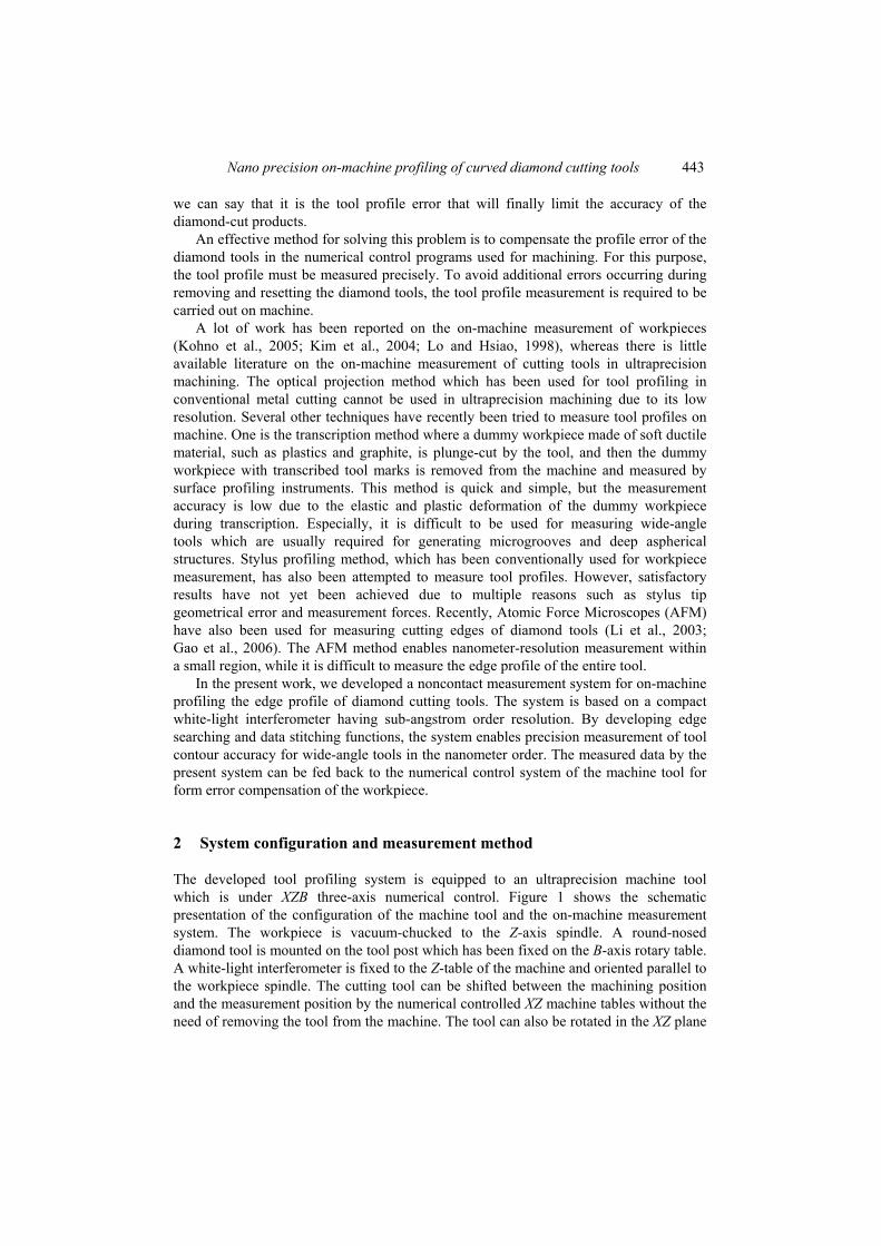
The developed tool profiling system is equipped to an ultraprecision machine tool which is under XZB three-axis numerical control. Figure 1 shows the schematic presentation of the configuration of the machine tool and the on-machine measurement system. The workpiece is vacuum-chucked to the Z-axis spindle. A round-nosed diamond tool is mounted on the tool post which has been fixed on the B-axis rotary table. A white-light interferometer is fixed to the Z-table of the machine and oriented parallel to the workpiece spindle. The cutting tool can be shifted between the machining position and the measurement position by the numerical controlled XZ machine tables without the need of removing the tool from the machine. The tool can also be rotated in the XZ plane
444 J. Yan et al.
by the B-axis rotary table, enabling the measurement of different orientations of a wide-angle tool.
Figure 1 Configuration of the machine tool and the on-machine tool profiling system
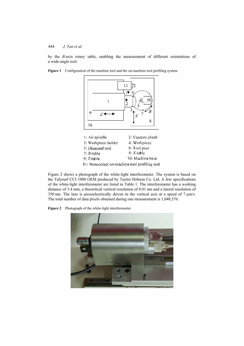
Figure 2 shows a photograph of the white-light interferometer. The system is based on the Talysurf CCI 1000 OEM produced by Taylor Hobson Co. Ltd. A few specifications of the white-light interferometer are listed in Table 1. The interferometer has a working distance of 3.4 mm, a theoretical vertical resolution of 0.01 nm and a lateral resolution of 350 nm. The lens is piezoelectrically driven in the vertical axis at a speed of 7 µm/s. The total number of data pixels obtained during one measurement is 1,048,576.
Figure 2 Photograph of the white-light interferometer
Nano precision on-machine profiling of curved diamond cutting tools 445
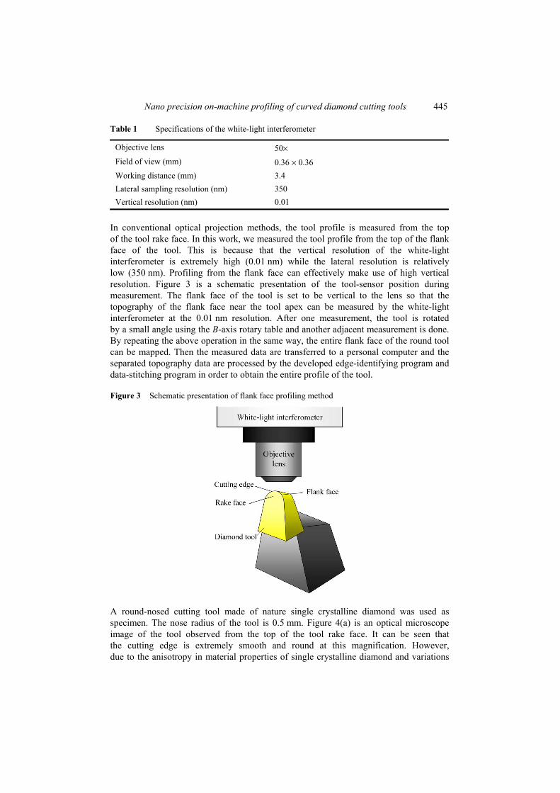
Table 1 Specifications of the white-light interferometer
Objective lens 50× Field of view (mm) 0.36 × 0.36 Working distance (mm) 3.4 Lateral sampling resolution (nm) 350 Vertical resolution (nm) 0.01
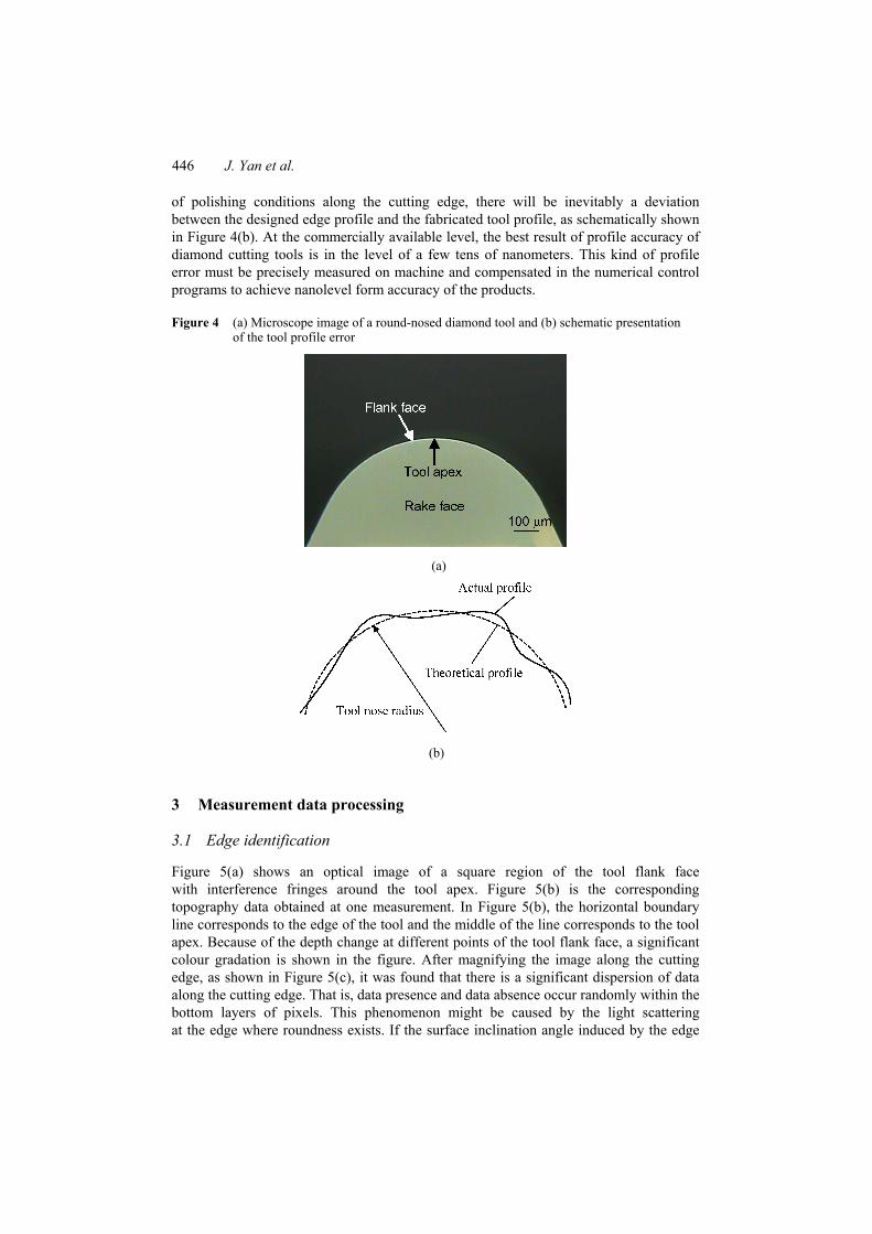
In conventional optical projection methods, the tool profile is measured from the top of the tool rake face. In this work, we measured the tool profile from the top of the flank face of the tool. This is because that the vertical resolution of the white-light interferometer is extremely high (0.01 nm) while the lateral resolution is relatively low (350 nm). Profiling from the flank face can effectively make use of high vertical resolution. Figure 3 is a schematic presentation of the tool-sensor position during measurement. The flank face of the tool is set to be vertical to the lens so that the topography of the flank face near the tool apex can be measured by the white-light interferometer at the 0.01 nm resolution. After one measurement, the tool is rotated by a small angle using the B-axis rotary table and another adjacent measurement is done. By repeating the above operation in the same way, the entire flank face of the round tool can be mapped. Then the measured data are transferred to a personal computer and the separated topography data are processed by the developed edge-identifying program and data-stitching program in order to obtain the entire profile of the tool.
Figure 3 Schematic presentation of flank face profiling method
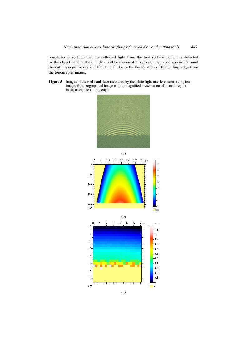
A round-nosed cutting tool made of nature single crystalline diamond was used as specimen. The nose radius of the tool is 0.5 mm. Figure 4(a) is an optical microscope image of the tool observed from the top of the tool rake face. It can be seen that the cutting edge is extremely smooth and round at this magnification. However, due to the anisotropy in material properties of single crystalline diamond and variations
446 J. Yan et al.
of polishing conditions along the cutting edge, there will be inevitably a deviation between the designed edge profile and the fabricated tool profile, as schematically shown in Figure 4(b). At the commercially available level, the best result of profile accuracy of diamond cutting tools is in the level of a few tens of nanometers. This kind of profile error must be precisely measured on machine and compensated in the numerical control programs to achieve nanolevel form accuracy of the products.
Figure 4 (a) Microscope image of a round-nosed diamond tool and (b) schematic presentation of the tool profile error
(a)
(b)
3 Measurement data processing
3.1 Edge identification
Figure 5(a) shows an optical image of a square region of the tool flank face with interference fringes around the tool apex. Figure 5(b) is the corresponding topography data obtained at one measurement. In Figure 5(b), the horizontal boundary line corresponds to the edge of the tool and the middle of the line corresponds to the tool apex. Because of the depth change at different points of the tool flank face, a significant colour gradation is shown in the figure. After magnifying the image along the cutting edge, as shown in Figure 5(c), it was found that there is a significant dispersion of data along the cutting edge. That is, data presence and data absence occur randomly within the bottom layers of pixels. This phenomenon might be caused by the light scattering at the edge where roundness exists. If the surface inclination angle induced by the edge
Nano precision on-machine profiling of curved diamond cutting tools 447
roundness is so high that the reflected light from the tool surface cannot be detected by the objective lens, then no data will be shown at this pixel. The data dispersion around the cutting edge makes it difficult to find exactly the location of the cutting edge from the topography image.
Figure 5 Images of the tool flank face measured by the white-light interferometer: (a) optical image; (b) topographical image and (c) magnified presentation of a small region in (b) along the cutting edge
(a)
(b)
(c)
448 J. Yan et al.
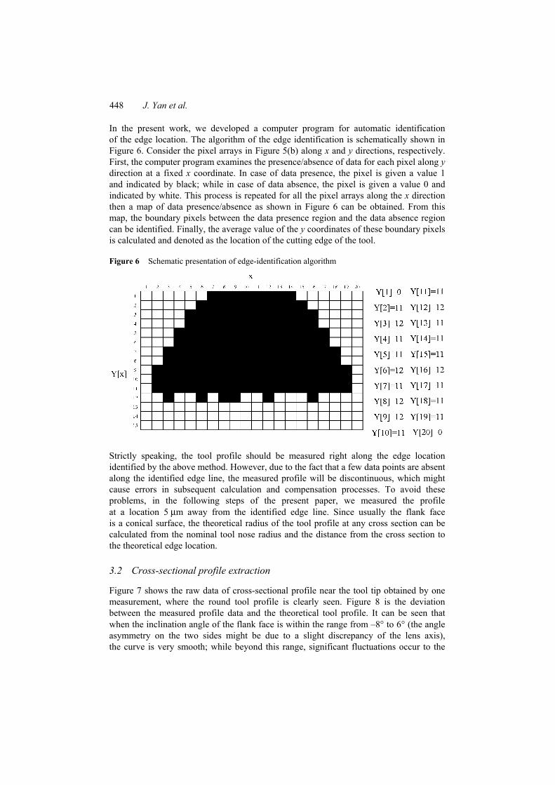
In the present work, we developed a computer program for automatic identification of the edge location. The algorithm of the edge identification is schematically shown in Figure 6. Consider the pixel arrays in Figure 5(b) along x and y directions, respectively. First, the computer program examines the presence/absence of data for each pixel along y direction at a fixed x coordinate. In case of data presence, the pixel is given a value 1 and indicated by black; while in case of data absence, the pixel is given a value 0 and indicated by white. This process is repeated for all the pixel arrays along the x direction then a map of data presence/absence as shown in Figure 6 can be obtained. From this map, the boundary pixels between the data presence region and the data absence region can be identified. Finally, the average value of the y coordinates of these boundary pixels is calculated and denoted as the location of the cutting edge of the tool.
Figure 6 Schematic presentation of edge-identification algorithm
Strictly speaking, the tool profile should be measured right along the edge location identified by the above method. However, due to the fact that a few data points are absent along the identified edge line, the measured profile will be discontinuous, which might cause errors in subsequent calculation and compensation processes. To avoid these problems, in the following steps of the present paper, we measured the profile at a location 5 µm away from the identified edge line. Since usually the flank face is a conical surface, the theoretical radius of the tool profile at any cross section can be calculated from the nominal tool nose radius and the distance from the cross section to the theoretical edge location.
3.2 Cross-sectional profile extraction
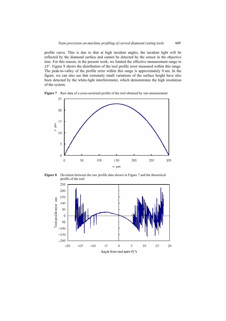
Figure 7 shows the raw data of cross-sectional profile near the tool tip obtained by one measurement, where the round tool profile is clearly seen. Figure 8 is the deviation between the measured profile data and the theoretical tool profile. It can be seen that when the inclination angle of the flank face is within the range from –8° to 6° (the angle asymmetry on the two sides might be due to a slight discrepancy of the lens axis), the curve is very smooth; while beyond this range, significant fluctuations occur to the
Nano precision on-machine profiling of curved diamond cutting tools 449
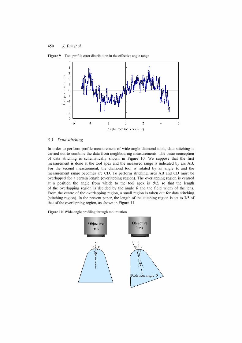
profile curve. This is due to that at high incident angles, the incident light will be reflected by the diamond surface and cannot be detected by the sensor in the objective lens. For this reason, in the present work, we limited the effective measurement range to ±5°. Figure 9 shows the distribution of the tool profile error measured within this range. The peak-to-valley of the profile error within this range is approximately 8 nm. In the figure, we can also see that extremely small variations of the surface height have also been detected by the white-light interferometer, which demonstrates the high resolution of the system.
Figure 7 Raw data of a cross-sectional profile of the tool obtained by one measurement
Figure 8 Deviation between the raw profile data shown in Figure 7 and the theoretical profile of the tool
450 J. Yan et al.
Figure 9 Tool profile error distribution in the effective angle range
3.3 Data stitching
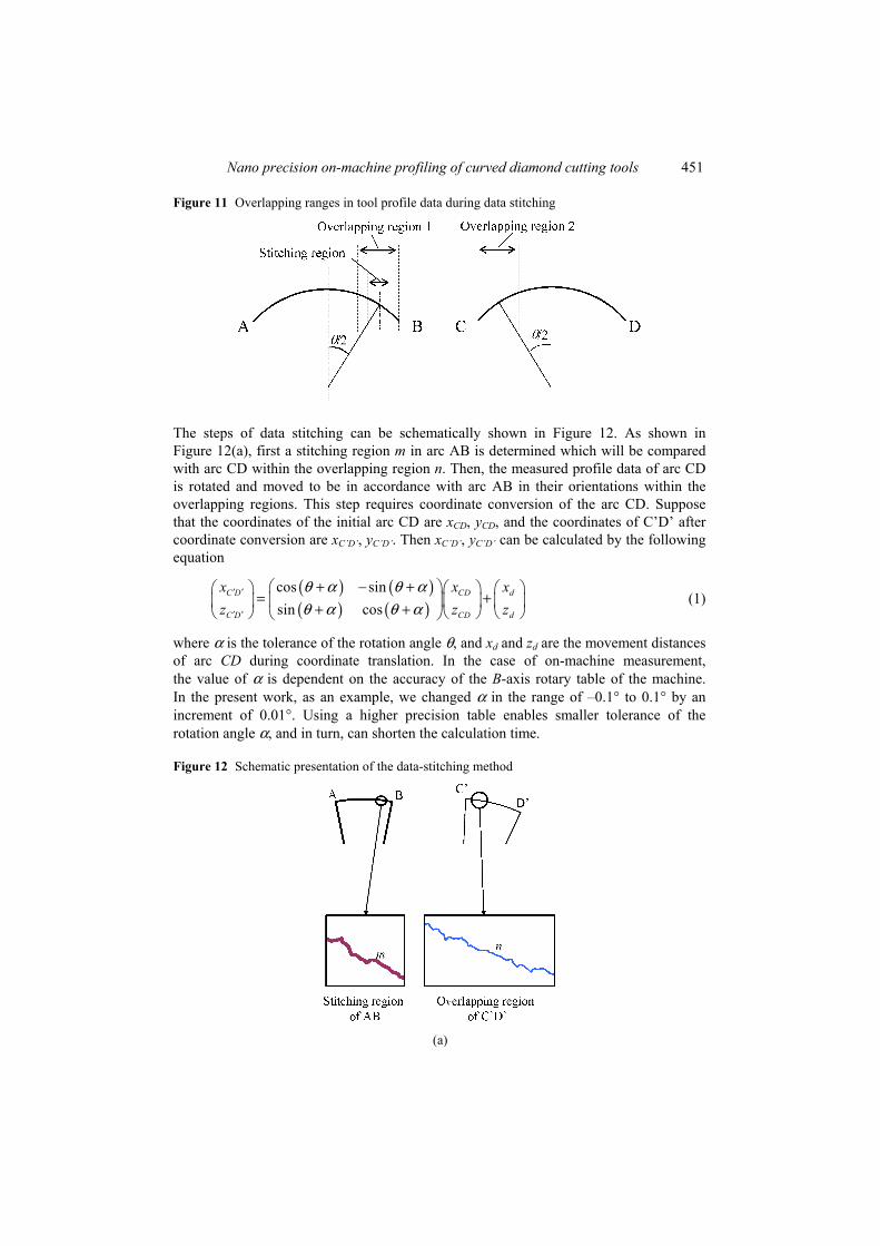
In order to perform profile measurement of wide-angle diamond tools, data stitching is carried out to combine the data from neighbouring measurements. The basic conception of data stitching is schematically shown in Figure 10. We suppose that the first measurement is done at the tool apex and the measured range is indicated by arc AB. For the second measurement, the diamond tool is rotated by an angle θ, and the measurement range becomes arc CD. To perform stitching, arcs AB and CD must be overlapped for a certain length (overlapping region). The overlapping region is centred at a position the angle from which to the tool apex is θ /2, so that the length of the overlapping region is decided by the angle θ and the field width of the lens. From the centre of the overlapping region, a small region is taken out for data stitching (stitching region). In the present paper, the length of the stitching region is set to 3/5 of that of the overlapping region, as shown in Figure 11.
Figure 10 Wide-angle profiling through tool rotation
Nano precision on-machine profiling of curved diamond cutting tools 451
Figure 11 Overlapping ranges in tool profile data during data stitching
The steps of data stitching can be schematically shown in Figure 12. As shown in Figure 12(a), first a stitching region m in arc AB is determined which will be compared with arc CD within the overlapping region n. Then, the measured profile data of arc CD is rotated and moved to be in accordance with arc AB in their orientations within the overlapping regions. This step requires coordinate conversion of the arc CD. Suppose that the coordinates of the initial arc CD are xCD, yCD, and the coordinates of C’D’ after coordinate conversion are xC’D’, yC’D’. Then xC’D’, yC’D’ can be calculated by the following equation
( ) ( )( ) ( )
cos sinsin cos
C D CD d
C D CD d
x x xz z z
θ α θ αθ α θ α
′ ′
′ ′
+ − + = + + +
(1)
where α is the tolerance of the rotation angle θ, and xd and zd are the movement distances of arc CD during coordinate translation. In the case of on-machine measurement, the value of α is dependent on the accuracy of the B-axis rotary table of the machine. In the present work, as an example, we changed α in the range of –0.1° to 0.1° by an increment of 0.01°. Using a higher precision table enables smaller tolerance of the rotation angle α, and in turn, can shorten the calculation time.
Figure 12 Schematic presentation of the data-stitching method
(a)
452 J. Yan et al.
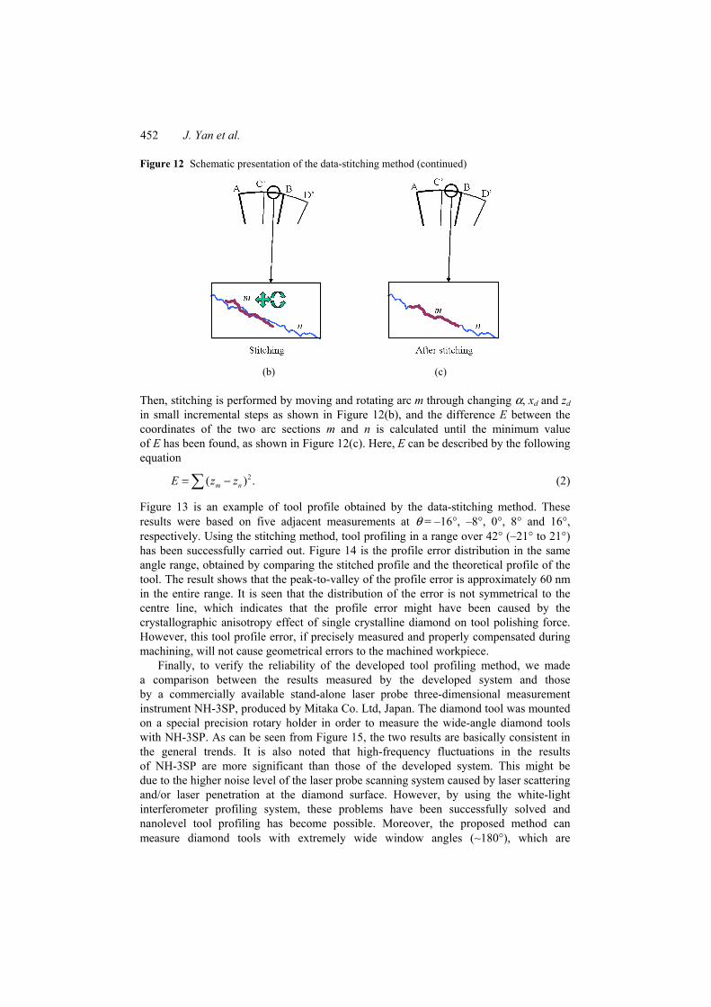
Figure 12 Schematic presentation of the data-stitching method (continued)
(b) (c)
Then, stitching is performed by moving and rotating arc m through changing α, xd and zd in small incremental steps as shown in Figure 12(b), and the difference E between the coordinates of the two arc sections m and n is calculated until the minimum value of E has been found, as shown in Figure 12(c). Here, E can be described by the following equation
2( ) .m nE z z= −∑ (2)
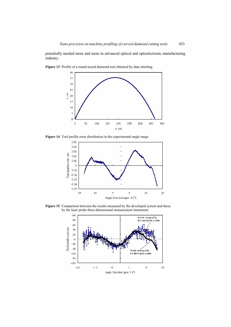
Figure 13 is an example of tool profile obtained by the data-stitching method. These results were based on five adjacent measurements at θ = –16°, –8°, 0°, 8° and 16°, respectively. Using the stitching method, tool profiling in a range over 42° (–21° to 21°) has been successfully carried out. Figure 14 is the profile error distribution in the same angle range, obtained by comparing the stitched profile and the theoretical profile of the tool. The result shows that the peak-to-valley of the profile error is approximately 60 nm in the entire range. It is seen that the distribution of the error is not symmetrical to the centre line, which indicates that the profile error might have been caused by the crystallographic anisotropy effect of single crystalline diamond on tool polishing force. However, this tool profile error, if precisely measured and properly compensated during machining, will not cause geometrical errors to the machined workpiece.
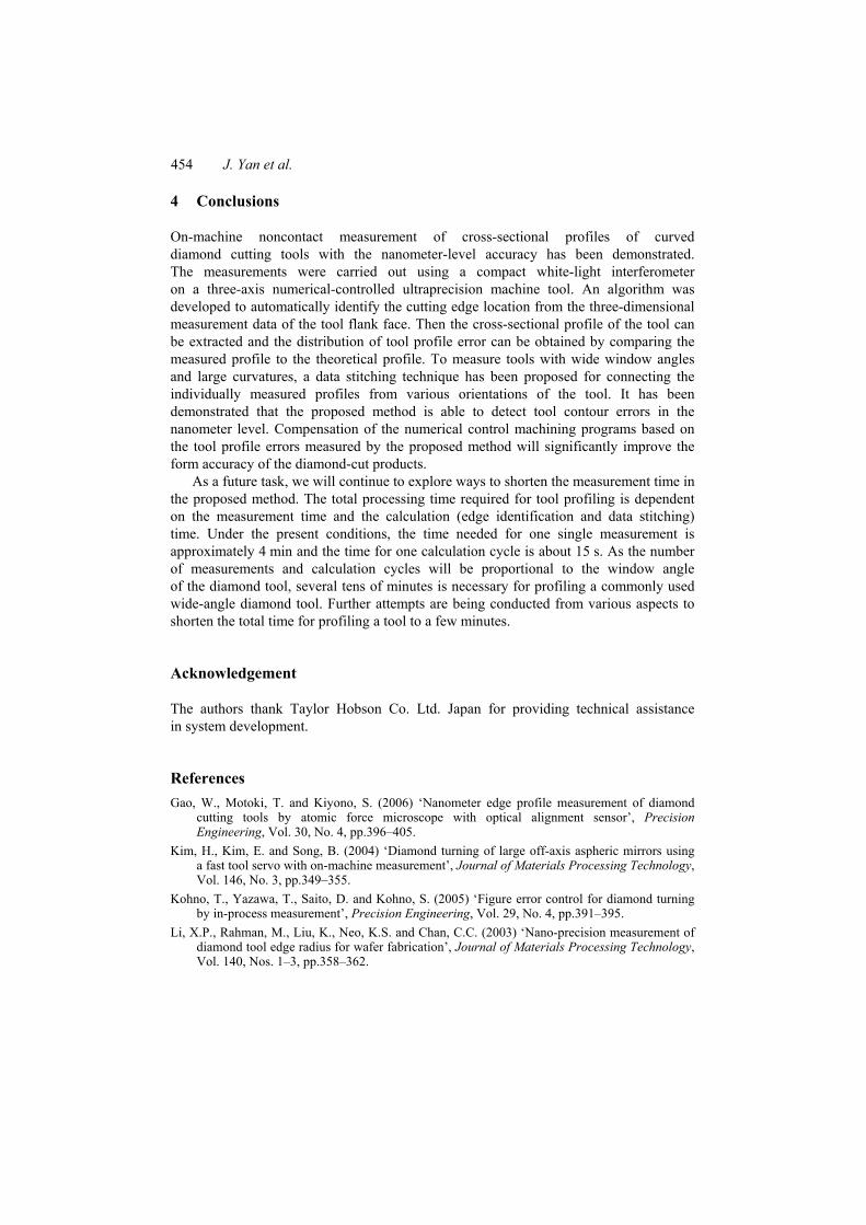
Finally, to verify the reliability of the developed tool profiling method, we made a comparison between the results measured by the developed system and those by a commercially available stand-alone laser probe three-dimensional measurement instrument NH-3SP, produced by Mitaka Co. Ltd, Japan. The diamond tool was mounted on a special precision rotary holder in order to measure the wide-angle diamond tools with NH-3SP. As can be seen from Figure 15, the two results are basically consistent in the general trends. It is also noted that high-frequency fluctuations in the results of NH-3SP are more significant than those of the developed system. This might be due to the higher noise level of the laser probe scanning system caused by laser scattering and/or laser penetration at the diamond surface. However, by using the white-light interferometer profiling system, these problems have been successfully solved and nanolevel tool profiling has become possible. Moreover, the proposed method can measure diamond tools with extremely wide window angles (~180°), which are
Nano precision on-machine profiling of curved diamond cutting tools 453
potentially needed more and more in advanced optical and optoelectronic manufacturing industry.
Figure 13 Profile of a round-nosed diamond tool obtained by data stitching
Figure 14 Tool profile error distribution in the experimental angle range
Figure 15 Comparison between the results measured by the developed system and those by the laser probe three-dimensional measurement instrument
454 J. Yan et al.
4 Conclusions
On-machine noncontact measurement of cross-sectional profiles of curved diamond cutting tools with the nanometer-level accuracy has been demonstrated. The measurements were carried out using a compact white-light interferometer on a three-axis numerical-controlled ultraprecision machine tool. An algorithm was developed to automatically identify the cutting edge location from the three-dimensional measurement data of the tool flank face. Then the cross-sectional profile of the tool can be extracted and the distribution of tool profile error can be obtained by comparing the measured profile to the theoretical profile. To measure tools with wide window angles and large curvatures, a data stitching technique has been proposed for connecting the individually measured profiles from various orientations of the tool. It has been demonstrated that the proposed method is able to detect tool contour errors in the nanometer level. Compensation of the numerical control machining programs based on the tool profile errors measured by the proposed method will significantly improve the form accuracy of the diamond-cut products.
As a future task, we will continue to explore ways to shorten the measurement time in the proposed method. The total processing time required for tool profiling is dependent on the measurement time and the calculation (edge identification and data stitching) time. Under the present conditions, the time needed for one single measurement is approximately 4 min and the time for one calculation cycle is about 15 s. As the number of measurements and calculation cycles will be proportional to the window angle of the diamond tool, several tens of minutes is necessary for profiling a commonly used wide-angle diamond tool. Further attempts are being conducted from various aspects to shorten the total time for profiling a tool to a few minutes.
Acknowledgement
The authors thank Taylor Hobson Co. Ltd. Japan for providing technical assistance in system development.
References Gao, W., Motoki, T. and Kiyono, S. (2006) ‘Nanometer edge profile measurement of diamond
cutting tools by atomic force microscope with optical alignment sensor’, Precision Engineering, Vol. 30, No. 4, pp.396–405.
Kim, H., Kim, E. and Song, B. (2004) ‘Diamond turning of large off-axis aspheric mirrors using a fast tool servo with on-machine measurement’, Journal of Materials Processing Technology, Vol. 146, No. 3, pp.349–355.
Kohno, T., Yazawa, T., Saito, D. and Kohno, S. (2005) ‘Figure error control for diamond turning by in-process measurement’, Precision Engineering, Vol. 29, No. 4, pp.391–395.
Li, X.P., Rahman, M., Liu, K., Neo, K.S. and Chan, C.C. (2003) ‘Nano-precision measurement of diamond tool edge radius for wafer fabrication’, Journal of Materials Processing Technology, Vol. 140, Nos. 1–3, pp.358–362.

Nano precision on-machine profiling of curved diamond cutting tools 455
Lo, C. and Hsiao, C. (1998) ‘A method of tool path compensation for repeated machining process’, Int. J. Machine Tools and Manufacture, Vol. 38, No. 3, pp.205–213.
Masuda, J., Yan, J. and Kuriyagawa, T. (2007) ‘Application of the NiP-plated steel molds to glass lens molding’, Proceedings of the 10th International Symposium on Advances in Abrasive Technology (ISAAT2007), 25–28 September, Dearborn, USA, pp.123–130.
Yan, J. (2006) Ultraprecision Machining for Fresnel Lenses and Their Molds, in Design and Manufacturing of Rear-Projection Optical Systems, Technical Information Institute, Tokyo.
Yan, J., Maekawa, K., Tamaki, J. and Kuriyagawa, T. (2005) ‘Micro grooving on single-crystal germanium for infrared Fresnel lenses’, Journal of Micromechanics and Microengineering, Vol. 15, pp.1925–1931.