Embed Size (px)
Citation preview

1
NanomechanicsofAerogels
Major Qualifying Project
Submitted to the Faculty of
Worcester Polytechnic Institute
in partial fulfillment of the requirements for the
Degree in Bachelor of Science in
Mechanical Engineering
By
___________________________________________________ Anubhav Prasad
_________________________
Dr. Balaji Panchapakesan
Director, Small Systems Laboratory (SSL)
Worcester Polytechnic Institute
Date: 04/28/2016
2
Abstract
The goal of this project is to study and analyze the nanomechanics of aerogels that are doped
with materials like Carbon Nanotubes (CNT) and Graphene. Aerogels provide the framework for
nanomaterial to exist in a three dimensional space. Doped Aerogels can potentially be used in
applications like enhanced thermal insulation and effective light trapping due to its multi-
functionality and superior mechanical properties. These hybrid aerogels are cheaper and easier to
fabricate than pure carbon aerogels, which are known to exhibit catalytic properties. By
analyzing the physical quantities in the aerogels such as molecular dynamics and mass, thermal
fluctuations, electrical conductivity, we can explore new areas of material science with carbon
nanotechnology [1].
Introduction
Nanomechanics is the science that deals with the fundamental mechanical properties like
thermal, elastic and kinetic quantities of a physical system at a nanoscale. It helps in explaining
some unexpected phenomenon’s and pathological behavior compared to our existing
understanding of the mechanics of macroscopic systems. The term aerogel is used to describe a
sol-gel material in which the liquid component of the gel is replaced with gas. This results a solid
nanostructure in tact without pore collapse in which 90~99% is air by volume. Aerogels can
exhibit a wide range of density from 1 kg.m-3 (lower than the density of air) to 1000 kg.m-3
(above the solid density), which induces dramatic changes in the properties. Aerogels can exhibit
versatile properties such as low thermal conductivity, dielectric constant, high specific surface
area, adjustable density and refractive index. This is due to the high porosity as well as dual
microscopic and macroscopic structural features. Aerogels are attractive materials, which can

3
find application in thermal insulations, chemical absorbents, sensors, catalytic carriers and space
explorations [2].
Aerogel was first invented in 1931 by Kistler, and was named so (air +gel) because the
liquid component inside the wet gel was replaced by air without damaging the solid
microstructure. The fabrication of aerogels has not taken off to its full potential due to the high
manufacturing costs and time consuming processes during synthesis. In 1968, Teichner’s group
worked on a significant innovation in which water-glass/water systems were replaced with
organic solvents to prepare aerogels using Tetramethyorthosilicate. Russo found a method to
introduce safer tetraethylorthosilicate in 1986, which led to the development of carbon dioxide
(CO2) supercritical fluid drying. More recently, unique aerogels such as carbon nanotube (CNT)
aerogels, graphene aerogels, silicon aerogels and carbide aerogels have been developed and
added to the aerogel community [2].
FirstAerogel
inventedbyKistlerin1931
SiO2aerogelsin1970's
Carbonandorganic
aeroeglsin1990's
GrapheneandCNTaerogelsin2010's
Fullpolymeraerogelsin2011
Figure1:Timelineoftheevolutionofaerogels

4
Although Silica aerogels are the most widely studied class, their potential applications in
industry, aerospace and daily life has been limited due to property analysis and hygroscopic
nature. Hybrid aerogels with multiple components exhibit enhanced properties and multi-
functions attracting more interest recently. In this paper, recent advances in the field of hybrid
aerogels will be discussed, with particular emphasis on their fabrication methods, structures,
properties and applications [3].
Theory
Silica aerogels contain more than 90% air and less than 10% solid silica. This is mixed with a
cross-link network structure with desirable properties such as low thermal conductivity, low bulk
density and high specific surface area. Such properties makes silica aerogels doped with carbon-
based nanomaterials the ideal candidate for various applications like filters for pollutants,
thermal insulators and drug delivery. High manufacturing costs, time and mechanical properties
severely impede scaling up and exploration in various applications.
Figure2:Numberofpaperspublishedyearlythroughthelastdecadeonaerogels

5
There are three possible methods of liquid removal from the hydrogel structure during
fabrication: (1) evaporation, (2) Critical Point Drying (CPD), and (3) freeze-drying. The CPD or
freeze-drying methods are the preferred options to remove the pore liquid effectively and still
preserve the gel networks of the aerogel. Selection between the two drying methods strongly
depends on the cost requirements of the fabricated aerogel [3].
Critical Point Drying Method (CPD)
The CPD method, also known as the supercritical drying method, has been widely used in
industry and research to preserve the porous structures in the production of aerogels. During the
CPD process, the transformation of liquid to gas takes place through the supercritical region
instead of crossing the liquid-gas boundary. The liquid and gas phases mixes within the
Figure3:Principlesofthreedryingmethods(evaporation,freeze-drying,andCPD)
6
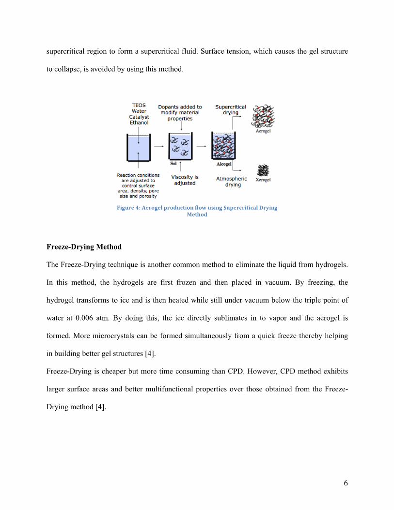
supercritical region to form a supercritical fluid. Surface tension, which causes the gel structure
to collapse, is avoided by using this method.
Freeze-Drying Method
The Freeze-Drying technique is another common method to eliminate the liquid from hydrogels.
In this method, the hydrogels are first frozen and then placed in vacuum. By freezing, the
hydrogel transforms to ice and is then heated while still under vacuum below the triple point of
water at 0.006 atm. By doing this, the ice directly sublimates in to vapor and the aerogel is
formed. More microcrystals can be formed simultaneously from a quick freeze thereby helping
in building better gel structures [4].
Freeze-Drying is cheaper but more time consuming than CPD. However, CPD method exhibits
larger surface areas and better multifunctional properties over those obtained from the Freeze-
Drying method [4].
Figure4:AerogelproductionflowusingSupercriticalDryingMethod

7
Nanomechanics of Carbon Nanotubes
Carbon nanotubes have great potential in material science due to their superior
mechanical properties over conventional materials. Prototypes for nano-electro-mechanical
devices such as high performance nanomotors, switches and oscillators based on carbon
nanotubes have shown great promise. The sp2 bonds present in the carbon nanotubes have a
Young’s modulus close to that of a diamond. The Van der Waal interactions are relatively weak
between the graphitic shells and this acts as a form of lubrication. The carbon nanotubes posses a
unique combination of small size, high stiffness, low density and high strength. They have a
broad range of electronic properties from metallic to p- and n-doped semiconducting [8].
High quality nanotubes can be produced in small quantities by methods based on cooling
carbon plasma than can be generated between two graphitic electrodes in an inert atmosphere
during an arc discharge. Other methods capable of producing CNTs in industrial quantities are
based on Chemical Vapor Deposition (CVD) and catalytic decomposition of various
hydrocarbons like methane or acetylene mixed with nitrogen or hydrogen in the presence of
Macro porosity d > 200nm
Meso porosity 5nm < d < 200nm
Micro porosity d < 5nm
Figure5:Porosityofaerogelsatdifferentscales

8
catalysts. This offers the possibility of controlling the growth of nanotubes by patterning the
catalyst and is more suitable for producing nanoscale structures with integrated CNTs [8].
Structure of Carbon Nanotubes
Carbon Nanotubes are considered to be single sheet of graphite that is curved up. It is the most
stable form of crystalline carbon rolled in to a cylindrical shape with axial symmetry. The
approximate diameter is 1.2 nm and can range between 0.7-10 nm. Rolling the graphite sheet
along one of the symmetry axis gives either a zigzag tube (m=0) or armchair tube (n=m). Rolling
up the sheet in a direction other than the symmetry axis gives a chiral nanotube [6]. The chiral
angle and circumference of the cylinder can be varied.
The structure of a single wall Carbon Nanotube is expressed in terms of one-dimensional unit
cell, defined by the vector:
𝒗 = 𝒏.𝒂𝟏 +𝒎.𝒂𝟐
Where a1 and a2 are unit vectors, and n and m are integers. Nanotubes that are constructed in this
way are called (n, m) nanotubes. In most cases, a1 = a2 = 2.49A.
Figure6:CarbonNanotubeconsistingof320carbonatomsdisplayingthearmchairandzigzagconfigurationsgeneratedbyAViZ
visualizationprogram
9
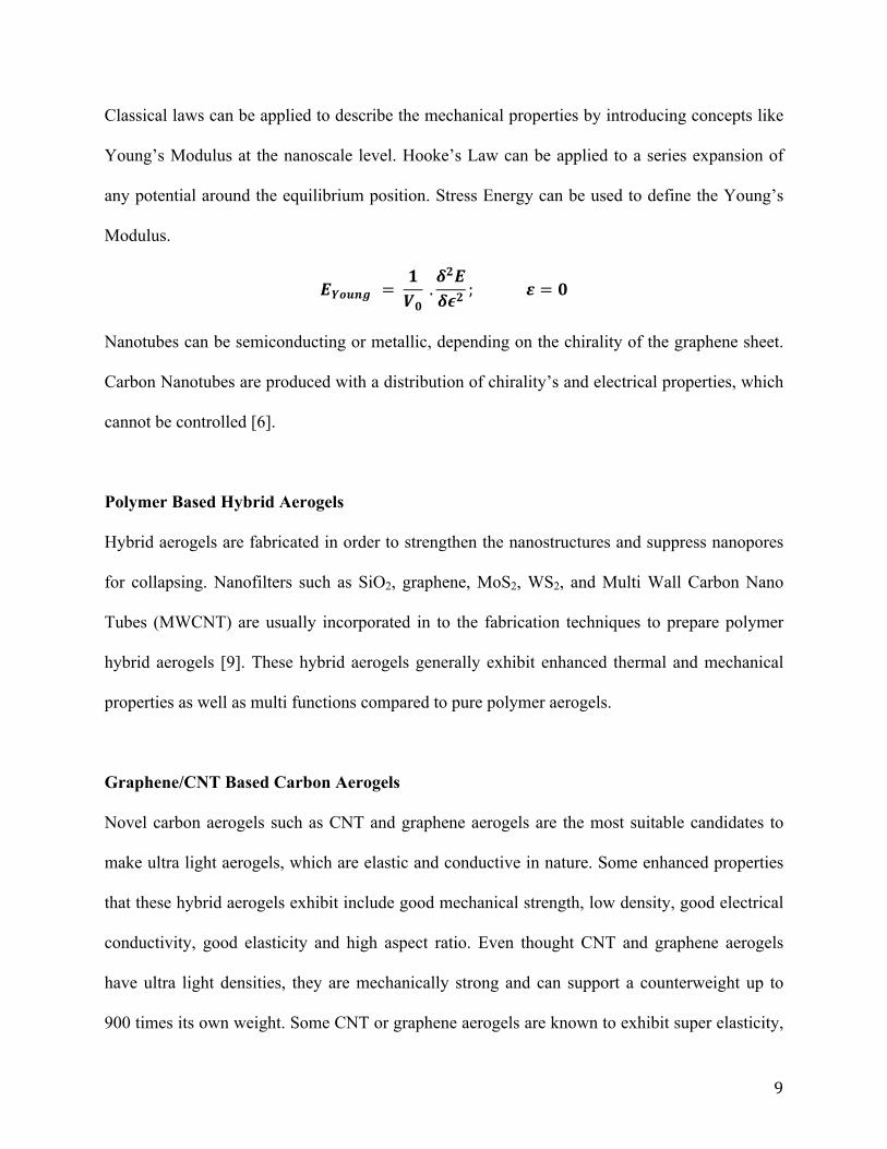
Classical laws can be applied to describe the mechanical properties by introducing concepts like
Young’s Modulus at the nanoscale level. Hooke’s Law can be applied to a series expansion of
any potential around the equilibrium position. Stress Energy can be used to define the Young’s
Modulus.
𝑬𝒀𝒐𝒖𝒏𝒈 = 𝟏𝑽𝟎
.𝜹𝟐𝑬𝜹𝝐𝟐 ; 𝜺 = 𝟎
Nanotubes can be semiconducting or metallic, depending on the chirality of the graphene sheet.
Carbon Nanotubes are produced with a distribution of chirality’s and electrical properties, which
cannot be controlled [6].
Polymer Based Hybrid Aerogels
Hybrid aerogels are fabricated in order to strengthen the nanostructures and suppress nanopores
for collapsing. Nanofilters such as SiO2, graphene, MoS2, WS2, and Multi Wall Carbon Nano
Tubes (MWCNT) are usually incorporated in to the fabrication techniques to prepare polymer
hybrid aerogels [9]. These hybrid aerogels generally exhibit enhanced thermal and mechanical
properties as well as multi functions compared to pure polymer aerogels.
Graphene/CNT Based Carbon Aerogels
Novel carbon aerogels such as CNT and graphene aerogels are the most suitable candidates to
make ultra light aerogels, which are elastic and conductive in nature. Some enhanced properties
that these hybrid aerogels exhibit include good mechanical strength, low density, good electrical
conductivity, good elasticity and high aspect ratio. Even thought CNT and graphene aerogels
have ultra light densities, they are mechanically strong and can support a counterweight up to
900 times its own weight. Some CNT or graphene aerogels are known to exhibit super elasticity,

10
which can be compressed multiple times and still recover most of the volume after the
compression release. CNT Aerogels can typically have an electrical conductivity of 3.2 X 10⁻²
S.cm-1, which can be enhanced to 0.67S.cm-1 by a high current pulse method while maintaining
the internal structures. This property has the potential to further expand the application fields of
aerogels materials including solar cells, sensors, electrodes and cold electron field emission [10].
Graphene based aerogels was first prepared by Wang in 2009. Thus was done by
converting GO solution in to the graphene aerogel by method of ultrasonic-induced gelation
followed by drying and thermal reduction. The graphene aerogels exhibit improved electrical
conductivity around 1 X 10² S.m-1, which is more than two orders of magnitude compared to
graphene assemblies with physical crosslinks. Graphene aerogels have a large surface area
~ 584 m2.g-1 and a pore volume of approximately 2.96 cm3.g-1thus being suitable candidates for
energy storage and sensing applications. Graphene aerogels can be modified in to different
macroscopic structures like 1D graphene aerogel fibers besides the 3D foam structures.
Graphene aerogel fibers have high specific area and good electrical conductivity. They also
possess great flexibility and can be folded, bent or stretched back to its original shape without
any internal fracture as shown in figure 7.
Figure7:SEMimagesofgrapheneaerogelfibers,straightandfoldedup

11
Graphene and CNT’s are two allotropes of carbon that has been investigated extensively in
recent years. Both allotropes individually possess multifunctional properties, such as high
electrical conductivity up to 104 S/cm, superior thermal conductivity of around 2000-5300
W/mK and a Young’s Modulus of ~1 TPa.
Fabrication of Graphene-CNT Hybrid Aerogels
Graphene/CNT hybrid aerogels have been successfully developed for applications such as
conductors, capacitive deionization and LIBs. The CNT’s can prevent graphene nanosheets from
stacking thereby enhancing the surface area of the gas. Chemical reduction method is the
preferred technique for fabrication of CNT-graphene hybrid aerogels because of the high quality
results obtained. The CNT’s are dispersed in the GO aq. Suspension by sonication. LAA or
hydrazine hydrate is used to reduce the mixture. A chemical bond between the graphene
nanosheets and the CNTs is formed. Heat treatment removes the defects from graphene
nanosheets and the CNTs. By simultaneous reduction, it is possible to chemically bond the two
carbon allotropes [11].
Figure8:NetworkStructureofgraphene-CNThybridaerogels

12
Other fabrication methods of CNT-graphene aerogels include directly freeze-drying the CNT-Go
mixture, CVD method or the hydrothermal method.
Properties of Graphene/CNT Aerogels
Graphene and CNT aerogels exhibit various multifunctional properties like high electrical
conductivity, low density, large surface area and good mechanical stability. The components
required to fabricate graphene/CNT aerogel are now commercially available because of
extensive research already done in this field. The novel properties that make aerogels an
interesting area of research are described in next section [3].
Electrical Properties
Graphene aerogels generally report and electrical conductivity within a large range from 0.1-100
S/m. The electrical conductivity graphene aerogels fabricated from the RF method can be
measured by a four-probe technique. The values obtained by conducting measurements average
up to 87 S/m. Graphene aerogels synthesized from the hydrothermal method apply the two-probe
technique to measure electrical conductivity. The measurements generally return a value ~0.1
S/m. There is a large variation between the two methods are due to different bonding formed
during different fabrication conditions. Various drying and reducing agents also affect the
electrical conductivity of graphene aerogels. The Supercritical Drying method yields a more
conductive aerogel than that of the freeze-drying process. By using a more efficient reducing
agent, the electrical conductivity of the aerogel can be enhanced [3].

13
CNT aerogels can achieve a slightly higher electrical conductivity compared to graphene
aerogels because of a more critical graphitic lattice. Different reactants during processing cause
this difference between the two kinds of aerogels. DWCNT aerogels can achieve an electrical
conductivity of up to 8 S/cm by the four probe measuring technique [5].
Mechanical Properties
Graphene/CNT aerogels are made up by individual nanosheets so mechanical properties like
strength and Young’s Modulus are far less than graphene and CNT monolayers. Therefore,
graphene/CNT aerogels are generally considered brittle. A study conducted by Zhang revealed
that graphene aerogels developed from supercritical drying was capable of supporting more than
14,000 times their own weight without much deformation. He also concluded that graphene
aerogels processed by freeze-drying methods could only support 3,300 times its own weight.
Figure9:InteractionbetweengrapheneandMWCNTinaerogels

14
Thus, supercritical drying achieves four times more strength than the freeze-drying method. CNT
aerogels can support up to 1000 times its own weight after thermal treatment.
Most experiments conducted to test mechanical properties for graphene/CNT aerogels are
compressive in nature due to the simple experimental setup involved and the brittle nature of
aerogels. The compressive stress-strain curve for graphene/CNT aerogels can be divided in to
three regions: elastic, yield and densification. The elastic region generally has 10% compressive
strains, the yield region experiences ~60% compressive strains and the densification region
experiences strains beyond 60%. From compressive tests, the Young’s Modulus for graphene
aerogels varies from 0.26 to 20 MPa, while those of CNT aerogels were between 0.12-65 MPa
[10].
Thermal Properties of Graphene/CNT Aerogels
The mesoporous structure of graphene/CNT aerogels may reduce the internal thermal resistance
and enhance the thermal efficiency by materials. However, thermal measurements and thermal
transport mechanisms of graphene/CNT aerogels is an area of limited research. Under the right
conditions, the thermal conductivity of graphene aerogels at 11% vol. of graphene and a low
surface area of 43 m2/g was 2.18 W/mK. To measure the thermal conductivity of graphene
aerogels, infrared microscopy techniques can be used. The measurements can be obtained using
1D steady-state heat conduction equation based on Fourier’s Law.
𝑭𝒐𝒖𝒓𝒊𝒆𝒓!𝒔 𝑳𝒂𝒘 𝒐𝒇 𝒉𝒆𝒂𝒕 𝒄𝒐𝒏𝒅𝒖𝒄𝒕𝒊𝒐𝒏 𝑸𝒄𝒐𝒏𝒅 = −𝒌𝑨𝒅𝑻𝒅𝒙 (𝑾𝒂𝒕𝒕)
The thermal conductivity of graphene aerogels can be between 0.12-0.36 W/mK. This is much
lower than pure graphene because of the low quality and small size of chemical derived graphene
nanosheets. Heat conduction through different forms of an aerogel scales as the density and

15
sound velocity. Figure 8 below shows that high-density silica will have a high heat transfer
value. The low-density silica will have a low heat transfer. By adding dopants to the aerogel, a
longer path is created thereby influencing a lower sound velocity and heat transfer.
There is no heat transfer in aerogels through convection. The pores in the aerogels are too small
to support convection cells. Also, at low pressures like 10 kPa, there may or may not be a gas
molecule within a given pore. Insulations made from aerogels experience no convection at the
walls [7].
Silica aerogels are transparent or translucent to visible light unless a dopant material like
graphene is added. The aerogels block most of the IR allowing its use as a Greenhouse covers.
However, IR around 4𝜇m passes through the pores reducing effectiveness of high temperature
insulation. By loading the aerogel with dopants, the IR windows can be closed. This can
drastically affect the heat insulation of the aerogel. Figure 11 below shows the transmission %
graph in silica aerogels vs carbon loaded aerogels.
Figure10:HeatConductionScalinginaerogels

16
Specific Surface Area of Graphene/CNT Aerogels
The Specific Surface Area (SSA) of the graphene/CNT aerogel can be determined using the
methylene blue (MB) adsorption method by UV-Vis spectroscopy. The test is conducted by
adding a known mass of graphene/CNT aerogel in to a known volume of methylene blue (MB)
solution of standard concentration. The process is followed by 2 hours sonication and stirring for
24 hours. This is done to reach the adsorption-desorption equilibrium of the methylene blue. By
centrifuging the mixture, the suspended particles are removed. The MB concentration is
measured through spectroscopy at a wavelength of 665nm compared with the initial
concentration. The SSA of the aerogel can be calculated using the following equation.
𝑺𝒑𝒆𝒄𝒊𝒇𝒊𝒄 𝑺𝒖𝒓𝒇𝒂𝒄𝒆 𝑨𝒓𝒆𝒂 𝒐𝒇 𝒕𝒉𝒆 𝑨𝒆𝒓𝒐𝒈𝒆𝒍 𝑺𝑺𝑨 = 𝑵𝑨𝑨𝑴𝑩𝑴𝑴𝑩
(𝑪𝟎 − 𝑪𝒆)𝑽
𝒎𝒔
Where 𝑵𝑨 represents Avogadro number (6.02 x 10²³/mol), 𝑨𝑴𝑩 is the covered area per MB
molecule typically assumed to be 1.35nm2, V is the volume of MB solution, 𝑴𝑴𝑩 is the relative
Figure11:Transmission%ofIRinaerogelsthroughradiation

17
molecular mass of MB, 𝒎𝒔 is the mass of the sample and 𝑪𝟎 and 𝑪𝒆 are the initial and
equilibrium concentration of MB.
Table1:StandardPropertiesofAerogels
Aerogel1 Silica2 Air
Dielectric Constant 1.007-2 ---- 1.0
Density (kg/m3) 3-400 2200 1
Surface Area (m2/g) 600-1500 ---- ----
Thermal Conductivity (W/mK) 0.01-0.3 1.3 1
Refractive Index 1.0-1.4 1.4 1.0
1 Silica Aerogel
2 Sintered Silica (Polycrystalline)
Reusability Test and Adsorption Capacity of Graphene/CNT Aerogels
The ASTMF726-99: Standard Test Method for Sorbent Performance of Adsorbents can be used
to measure the adsorption capacity of aerogels. This test uses different kinds of oils such as
gasoline, organic solvents and fats. The weight of graphene/CNT adsorbents is recorded after
immersing it in the oil for 1 hour and compared with the initial weight of the aerogel. The
adsorption capacity (Q) can be calculated using the weight of the aerogel before and after the
adsorption test by:
𝑨𝒅𝒔𝒐𝒓𝒑𝒕𝒊𝒐𝒏 𝒐𝒇 𝑨𝒆𝒓𝒐𝒈𝒆𝒍𝒔 𝑸 = 𝒘𝒕𝒇𝒊𝒏𝒂𝒍 − 𝒘𝒕𝒊𝒏𝒊𝒕𝒊𝒂𝒍
𝒘𝒕𝒊𝒏𝒊𝒕𝒊𝒂𝒍

18
The most efficient results are obtained when the experiment is conducted three times and an
average value of adsorption capacity can be calculated.
Process Variables
Graphene hydrogels are formed by the pi-pi staking during reduction. The reducing agent (LAA,
HI or NaHSO3) impacts the electrical properties and thermal stability of graphene aerogels.
CNT-graphene aerogels formation can also take place due to pi-pi bond interaction between the
graphene nanosheets as well as between the graphene and CNTs. During the reduction process,
majority of the CNTs wrap inside the 2D network of graphene hydrogel, while the remaining
CNTs forms pi-pi interaction with the reduced graphene oxide sheet [5].
Effect of Reducing Agents and CNTs on GAs
Graphene Aerogels are characterized by nitrogen adsorption/desorption measurements to get
values like specific surface area and pore size. This can be obtained by the Brunauer-Emmett-
Figure12:Variousstagesofabsorptionanddesorptionoforganicliquidsinaerogels
19
Teller method. The surface area of graphene aerogels reduced by LAA, HI and NaHSO3 give
different values. By implementing the process of annealing, the functional groups can be further
removed causing the aerogels to condense further. There is no clear explanation for the
difference in values due to different reducing agents. It is possible that by annealing, the pi-pi
interaction among graphene sheets may decrease [5].
Effect of CNTs on GAs
Different concentrations of CNTs can be added to the Gas to form different CNT-graphene
hybrid aerogels. The surface area of CNT-graphene aerogels increase due to a higher
concentration of CNTs up to 1 mg/mL . This is due to the additional surface area of the dispersed
CNTs and the separation of graphene nanosheets by the CNTs during the formation processes.
However, higher CNT concentrations may reduce the surface area of the aerogel as it may block
the pores by bundling [5].
Aerogel Use in Reduction of Casimir Force
Aerogels are highly porous materials typically fabricated from SiO2 using sol-gel techniques.
Due to properties like low thermal conductivity, good mechanical strength and luminescence,
low density, and porosity as high as 95%, aerogels are fast becoming a promising material in the
semiconductor industry. Aerogels have the lowest refraction index of all solids in the visible
range n ~ 1.05 depending on the porosity. Air voids in the aerogels dominate the dielectric
behavior rather than the solid part. The Casimir effect is a small attractive force that acts between
two parallel-uncharged conducting plates due to quantum vacuum fluctuations of the
electromagnetic field. Aerogels can be used to reduce the magnitude of the Casimir force on a

20
nanoscale. In order to calculate the magnitude of Casimir Force, we will need to analyze the
dielectric response of the aerogel in a broad frequency range. Methods such as Clausis-Mossotti
approximation and Looyenga’s approach can be used to study the effective optical properties of
high and low porous media respectively [11].
𝑪𝒍𝒂𝒖𝒔𝒊𝒔−𝑴𝒐𝒔𝒔𝒐𝒕𝒕𝒊 𝒇𝒐𝒓 𝒅𝒊𝒆𝒍𝒆𝒄𝒕𝒓𝒊𝒄 𝒑𝒆𝒓𝒎𝒊𝒕𝒕𝒊𝒗𝒊𝒕𝒚 𝜺− 𝟏𝟒𝝅 𝑬 = 𝑵𝒌𝜶𝒌(𝑬𝒊)𝒌
𝒌
Hybrid Aerogel Applications
Hybrid Aerogels have some unique characteristics that make them attractive to use in science
and technology. Some general applications of Hybrid Aerogels perspective to properties are
listed below in Table 2.
Table2:Potentialapplicationsofhybridaerogels
Property Feature Application
Acoustic 1. Low speed of sound
1. Sound proof rooms 2. Ultrasonic distant sensors
Optical 1. Transparent 2. Multiple composition 3. Low refractive index
1. Light weight optics 2. Light guides 3. Cherenkov detectors
Mechanical 1. Elastic 2. Light Weight
1. Energy absorber 2. Velocity particle trap
Thermal conductivity
1. Good insulating solid 2. High Temp.
Threshold
1. Construction and insulation 2. Automobiles, space vehicles
Density 1. Lightest synthetic solid
2. High Surface Area
1. Catalysis 2. Sensors 3. Fuel Storage 4. Filters for gaseous pollutants
Electrical 1. Low dielectric constant
2. High dielectric strength
1. Dielectrics for Integrated Circuits 2. Capacitors

21
Aerogels as an Absorbent
Synthesis of flexible and super hydrophobic aerogels can be used as an absorbent. The
absorption and desorption capacity of doped silica aerogels can be investigated using eleven
solvent and three oils. A. Venkateshwara Rao introduced this method and can be applied to our
methodology [4]. The mass of a liquid that rises into the aerogel pores is given by the following
formula.
𝑴𝒂𝒔𝒔 𝒐𝒇 𝒍𝒊𝒒𝒖𝒊𝒅 𝒊𝒏 𝒂𝒆𝒓𝒐𝒈𝒆𝒍 𝒑𝒐𝒓𝒆𝒔: 𝟐𝝅𝒓𝜸𝒄𝒐𝒔𝜽 =𝒎𝒈
When liquids are involved that completely wet the surface, the contact angle 𝜃 is zero and for
such surfaces, the mass is represented by:
𝑴𝒂𝒔𝒔 𝒐𝒇 𝒍𝒊𝒒𝒖𝒊𝒅 𝒊𝒏 𝒂𝒆𝒓𝒐𝒈𝒆𝒍 𝒑𝒐𝒓𝒆𝒔 𝒘𝒊𝒕𝒉 𝒛𝒆𝒓𝒐 𝒂𝒏𝒈𝒍𝒆: 𝟐𝝅𝒓𝜸 =𝒎𝒈
or
𝜸𝝆 = 𝒌𝑽
Where r is the radius of aerogel pores, V is the volume of the absorbed liquid, 𝛒 is the liquid
density and k=g/2𝝅r is a constant. As the surface tension of the liquid increases, the mass of the
liquid absorbed also increases linearly. Super hydrophobic aerogels can be efficient absorbents
of oils and organic liquids [4].
Aerogels as a Sensor
Aerogels have a high porosity and surface area overall that make them potential
candidates for use as a sensor. Silica aerogels doped with nanoparticles exhibits reduced
electrical resistivity with increasing humidity. Hybrid Aerogels that have modified surfaces are
less affected by humidity as compared to hydrophilic aerogels. They can be used as
anticorrosive, hydrophobic agents.

22
Aerogels as Materials with Low Dielectric Constant
SiO2 aerogel films have found great interest in Integrated Circuit applications because of
properties such as low dielectric constant, high porosity and high thermal stability. Earlier
investigations in this field conducted by Park reveled that the dielectric constant for silica thin
films of silica aerogels was approximately 1.9. By using ambient drying process using n-heptane
as a drying solvent, the SiO2 aerogel films can achieve a low dielectric constant of 2.0 with
79.5% porosity [11].

23
References
[1] S. Dorcheh and M. H. Abbasi, "Silica aerogel; synthesis, properties and characterization,"
Journal of Materials Processing Technology, vol. 199, pp. 10-26, 2008.
[2] Fan, Zeng, Daniel Tng, Clarisse Lim, and Hai Duong. "Thermal and Electrical Properties of
Graphene/carbon Nanotube Aerogels." Science Direct, 18 Jan. 2014. Web.
[3] Zuo, Lizeng, Youfang Zhang, Yue Miao, and Longsheng Zhang. "Polymer/Carbon-Based
Hybrid Aerogels: Preparation, Properties and Applications." State Key Laboratory of Molecular
Engineering of Polymers, 9 Oct. 2015. Web.
[4] Duong, Hai, Zeng Fan, and Son Nguyen. "Graphene/Carbon Nanotube Aerogels." N.p., 19
Oct. 2015. Web.
[5] Kabiri, Shervin, Diana Tran, Dusan Losic, and Tariq Altalhi. "Outstanding Adsorption
Performance of Graphene–carbon Nanotube Aerogels for Continuous Oil Removal." The
University of Adelaide, 14 May 2014. Web.
[6] A. M. Buckley and M. Greenblatt, "The Sol-Gel Preparation of Silica Gels," Journal of
Chemical Education, vol. 71, pp. 599-602, 1994.
[7] C. J. Brinker and G. W. Scherer, Sol-Gel ScienceThe Physics and Chemistry of Sol-Gel
Processing: Academic Press, Inc., 1990.

24
[8] M. A. Worsley, P. J. Pauzauskie, T. Y. Olsen, J. Biener, J. H. S. Jr., and T. F. Baumann,
"Synthesis of Graphene Aerogel with High Electrical Conductivity," Journal of American
Chemical Society, vol. 132, pp. 14067-14069, 2010.
[9] M. Koebel, A. Rigacci, and P. Achard, "Aerogel-based thermal superinsulation: an
overview," Journal of Sol-Gel Science and Technology, vol. 63, pp. 315-339, 2012.
[10] J. Zou, J. Liu, A. S. Karakoti, A. Kumar, D. Joung, Q. Li, et al., "Ultralight Multiwalled
Carbon Nanotube Aerogel," ACS Nano, vol. 4, pp. 7293-7302, 2010.
[11] M. B. Bryning, D. E. Milkie, M. F. Islam, L. A. Hough, J. M. Kikkawa, and A. G. Yodh,
"Carbon Nanotube Aerogels," Advanced Materials, vol. 19, pp. 661-664, 2007.