Embed Size (px)
Citation preview
Nanopores in carbon nitride nanotubes: Reversible hydrogen storage sitesSe Yun Kim, Hyun Seok Kim, Saji Augustine, and Jeung Ku Kang Citation: Applied Physics Letters 89, 253119 (2006); doi: 10.1063/1.2422912 View online: http://dx.doi.org/10.1063/1.2422912 View Table of Contents: http://scitation.aip.org/content/aip/journal/apl/89/25?ver=pdfcov Published by the AIP Publishing Articles you may be interested in Hydrogen adsorption/desorption in functionalized single-walled carbon nanotubes AIP Conf. Proc. 1447, 253 (2012); 10.1063/1.4709975 Hydrogen storage enhanced in Li-doped carbon replica of zeolites: A possible route to achieve fuel cell demand J. Chem. Phys. 130, 174717 (2009); 10.1063/1.3122382 Hydrogen storage in pure and Li-doped carbon nanopores: Combined effects of concavity and doping J. Chem. Phys. 128, 144704 (2008); 10.1063/1.2900964 Hydrogen storage and desorption properties of Ni-dispersed carbon nanotubes Appl. Phys. Lett. 88, 143126 (2006); 10.1063/1.2189587 Nanopores of carbon nanotubes as practical hydrogen storage media Appl. Phys. Lett. 87, 213113 (2005); 10.1063/1.2133928
This article is copyrighted as indicated in the article. Reuse of AIP content is subject to the terms at: http://scitation.aip.org/termsconditions. Downloaded to IP: 157.211.3.38
On: Mon, 01 Dec 2014 04:17:09
Nanopores in carbon nitride nanotubes: Reversible hydrogen storage sitesSe Yun Kim, Hyun Seok Kim, Saji Augustine, and Jeung Ku Kanga�
Department of Materials Science and Engineering, Korea Advanced Institute of Science and Technology,Daejeon 305-701, Republic of Korea
�Received 21 September 2006; accepted 22 November 2006; published online 22 December 2006�
Experimental and theoretical approaches are used to determine hydrogen storage mechanisms innanopores of multiwalled carbon nitride nanotubes �MWCNNTs�. First, the authors produce�0.6 nm pores on the stems of MWCNNTs by plasma-enhanced chemical vapor deposition. Next,thermal desorption spectra were measured and obtained two different peaks. This is explained byhydrogen desorption barriers of 0.36–0.50 eV attributed to two different types of �0.6 nm pores.Moreover, H2 adsorption between complete interlayers is found to be endothermic by 1.27 eV. Inthis respect, open channels and �0.6 nm pores on MWCNNTs are considered to provide the routefor reversible hydrogen storage. © 2006 American Institute of Physics. �DOI: 10.1063/1.2422912�
Hydrogen is an attractive fuel alternative to conventionalhydrocarbon fuels because water is the only product whenhydrogen burns with oxygen in a fuel cell. On the otherhand, one of the main issues for hydrogen economy is thedevelopment of a suitable hydrogen storage material that issmall, light, and safe. In addition, achieving at least theweight percent of 6.5 wt % is the goal of the U.S. Depart-ment of Energy. Because of these requirements, early in thedevelopment of hydrogen storage materials various carbonmaterials were investigated.1 This is because carbon materi-als can give many different types of structures, which pro-vide a variety of hydrogen storage sites. For example, thecarbon nanotubes �CNTs� having high surface-to-volume ra-tios were suggested as ideal structures for fast kinetics be-cause of their reversible characteristics during hydrogenationand dehydrogenation.
Despite these advantages, recent studies2,3 have shownthat the hydrogen stored on a pristine CNT is less than0.01 wt % at 1 bar condition and room temperature. More-over, the recent experiment by Lawrence and Xu4 confirmedthat only 0.6 wt % hydrogen at room temperature was ad-sorbed on the CNT bundle at the high pressure condition of100 bars. Also our recent study5 showed that liquefaction ofH2 molecules on the CNT bundle still occurs at the lowtemperature of about 80 K under the pressure conditionslarger than 20 bars. In this respect, to use pristine CNTs ashydrogen storage media could be impractical for practicalapplications at atmospheric conditions due to the expensivecryogenic process for hydrogen adsorption �80–150 K at1 bar� on the CNT surfaces.
On the other hand, here we find that nanopores with�6 Å diameters on the stems of the nanotubes are capable ofgiving great potentials to reversible hydrogen storage sites.This is because the physical interaction distance between theH2 molecule and C atom of a carbon-based nanotube is�3 Å. In this respect, the minimum diameters of nanoporesfor possible penetration of H2 should be twice of �3 Å �=�6 Å�. However, if carbon atoms bonded in the perimeter ofcarbon-based nanopores could be replaced with other ele-ments such as nitrogen atoms �or hereafter called as the car-
bon nitride nanotube or CNx�, the physical interaction diam-eters of N-doped nanopores for possible penetration of H2
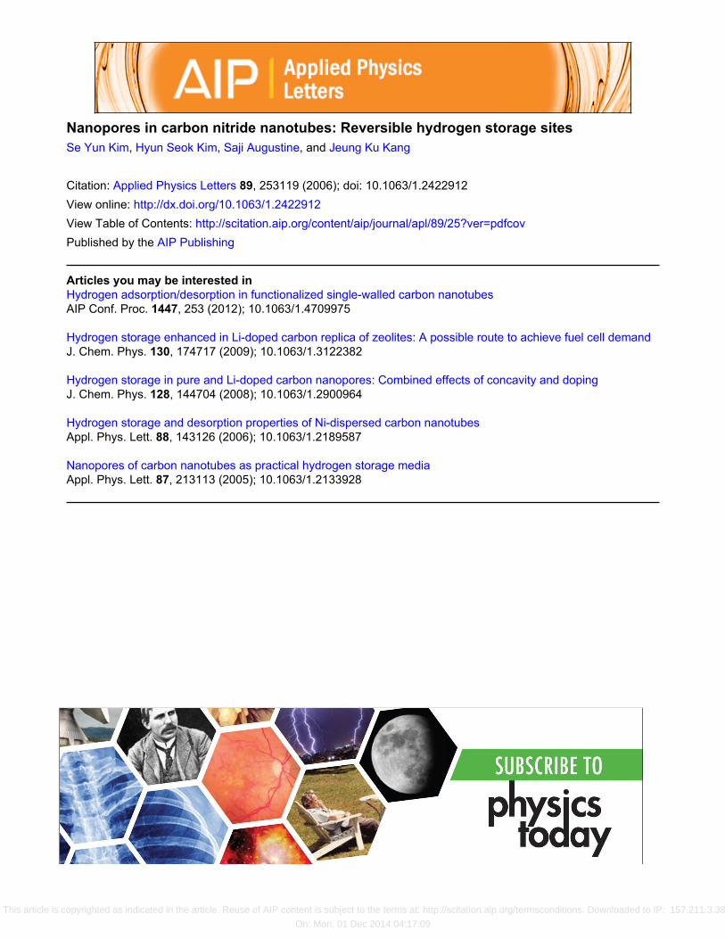
could be reduced such that hydrogen could desorb at thetemperatures ranging from room temperature to 80 °C,which is the ideal condition for various applications. Here,we report that the carbon nitride nanotube having 6 Å poresis an ideal structure being capable of satisfying the requiredtemperature condition. Our experiments also demonstratethat versatile 6 Å pores could be created on the stems of themultiwalled carbon nitride nanotubes with the uniform dis-tribution, as shown in Fig. 1.
Carbon nitride nanotubes were synthesized using a mi-crowave plasma-enhanced CVD �PECVD�. First, a7-nm-thick Co layer was deposited on a SiO2/Si substratevia rf sputtering with 100 W rf power. The thickness of SiO2on the Si wafer was 500 nm. Then, the substrate was moved
a�Author to whom correspondence should be addressed; FAX: �82-42-869-3310; electronic mail: [email protected]
FIG. 1. �Color online� �a� High-resolution transmission electron microscope�HRTEM� image of a carbon nitride nanotube �CNx, x=0.008�, where thewhite circle represents the disconnected graphene layers corresponding tothe nanopores. �b� The Horvath-Kawazoe pore size distribution obtainedfrom the carbon nitride nanotubes grown with “a” �15 SCCM of CH4 and85 SCCM of N2�, “b” �15 SCCM of CH4, 55 SCCM of N2, and 30 SCCMof H2�, and “c” �15 SCCM of CH4, 81 SCCM of N2, and 4 SCCM of O2�,and �c� HRTEM image of carbon nitride nanotubes with dispersed Ninanoparticles.
APPLIED PHYSICS LETTERS 89, 253119 �2006�
0003-6951/2006/89�25�/253119/3/$23.00 © 2006 American Institute of Physics89, 253119-1 This article is copyrighted as indicated in the article. Reuse of AIP content is subject to the terms at: http://scitation.aip.org/termsconditions. Downloaded to IP: 157.211.3.38
On: Mon, 01 Dec 2014 04:17:09

to the PECVD chamber and the chamber was evacuated toabout 0.1 Torr. Next, the substrate was heated to 720 °C in avacuum by a halogen lamp. After that, the N2 gas was flowedinto the chamber and the substrate was treated by the N2plasma created using a microwave power of 750 W for1 min. Then, 15 SCCM �SCCM denotes cubic centimeter perminute at STP� of CH4 was introduced at 850 °C, either withN2 only or with N2 and H2 gases simultaneously, and themicrowave power was increased to 800 W. Different flowrates of N2, H2, and O2 gases were used in each experiment.The growth time was 20 min. The morphology and the struc-ture of the as-grown samples were analyzed via high-resolution transmission electron microscopy �HRTEM� �FE-TEM F20, Phillips�. The pore distribution of the grownnanotubes was analyzed as received from the isotherm of theN2 adsorption on the samples �Autosorb-3B, Quantachrome�.Also for direct observation of nanopores created on the stemsof the nanotubes, Ni nanoparticles were dispersed on theirstems by the method described in the previous work.6 Inaddition, the gas chromatograph equipped with the thermalconductivity detection method and the selected capillary col-umn �Carboxen 1006PLOT� are used to observe the hydro-gen desorption property.
Figure 1�a� shows the HRTEM image of a carbon nitridenanotube where the disconnected graphene layers �in acircle� represent nanopores, while Fig. 1�b� compares thepore size distribution of the as-grown nanotubes with respectto different flow rates of N2, H2, and O2 gases. The �6 Åpores are shown on all the grown nanotubes. The volume of�6 Å pores increased for the samples grown with an in-creased nitrogen flowing rate, with the minimum volume ob-served for those nanotubes grown at 30 SCCM of hydrogen,55 SCCM of nitrogen, and 15 SCCM of methane. In addi-tion the peak around 16 Å disappeared after an inclusion of30 SCCM of H2 during growth. On the other hand, nano-tubes grown with 4 SCCM of oxygen had the largest volumeof �6 Å pores, which was about three times larger than thatof nanotubes grown with 30 SCCM of H2, 55 SCCM of ni-trogen, and 15 SCCM of CH4. Figure 1�c� shows that Ninanoparticles can be uniformly dispersed, implying that na-nopores were uniformly created on our synthesized nano-tubes.
To determine the origin of the different volumes of nan-opores, x-ray photon spectroscopy �XPS� analyses were per-formed. We were confirmed that our samples were carbonnitride nanotubes from the N 1s signal of the XPS spectrumof the as-grown sample, as shown in Fig. 2. The N 1s XPSspectra were divided by three Lorentz fits: �a� 398.2 eV isthe tetrahedral nitrogen phase �N1� bonded to ansp3-hybridized carbon, �b� 401.3 eV is the trigonal nitrogenphase �N2� bonded to an sp2-coordinated carbon, and �c�404.8 eV is the molecular N2, where the binding energy of404.8 eV is lower than original binding energy of free N2 gasof 409.9 eV because of the screening effect between N 1score hole and matrix. The molecular N2 may be attributed tothe trapped N2 gas in the holes between the nodes in the CNxnanotubes. The ratio of peak intensities of the N1 or N2�INi / IN1+ IN2� was examined. The relative peak intensity,0.378, for tetrahedral nitrogen atoms bonded to ansp3-hybridized carbon �IN1/ IN1+ IN2� of CNx nanotubesgrown with only N2 and CH4 is stronger than the 0.306 fornanotubes grown with N2, H2, and CH4. In addition, themore N contents the nanotubes have, the poorer the crystal-
linity they have. On the other hand, in contrast with carbonnanotubes, the CNx nanotubes have open edges of graphenelayers on the nanotube stems. The open edges of graphenelayers are considered to be caused by N substitution for Catoms on the stems of CNx nanotubes. The intensities of thebinding energies at 404.8 eV are different from the nano-tubes with different growing gases. The nanotubes with15 SCCM CH4 and 85 SCCM N2 have the strongest inten-sity from among the three samples. Moreover, the nanotubeswith 15 SCCM CH4, 55 SCCM of N2, and 30 SCCM of H2have the lowest molecular N2 binding energy peak. This re-sult indicates that the amount of N2 during nanotubes’growth has an important effect on the structure of as-grownnanotubes. Interestingly, the nanotubes having the largestvolume of �6 Å pores were those grown with 4 SCCM ofO2. The relative intensity of the N1 peak �IN1/ IN1+ IN2� ofthe nanotubes grown with 4 SCCM of O2 is 0.448, which isthe highest, indicating that these nanotubes have the poorestcrystallinity among the grown nanotubes. Therefore, the N1s XPS spectra can explain the different volumes of porescreated on the samples.
We used both the experiment using thermal desorptionspectra and the first-principles calculation method, as sum-marized in Fig. 3, to determine hydrogen-ensnaring mecha-nism in nanopores with �0.6 nm sizes of carbon nitridenanotubes. The top and side models used for simulation for�0.6 nm N-doped nanopores are shown in Fig. 3�a�, whereN-doped �or undoped� nanopores are made of alternating N�or C� and C atoms after one benzene ring unit has beenremoved from the carbon graphene layer. We use the PW91�Ref. 7� method in the CASTEP �Ref. 8� program to investi-gate hydrogen storage and desorption mechanisms on about6 Å pores created in the stems of double-walled nanotubeswith periodic boundary conditions, where all atoms are de-scribed using nonlocal norm-conserving Vanderbilt scalarpseudopotentials.9 The set of k points used to expand themolecular wave function is based on the Monkhorst-Pack
FIG. 2. �Color online� N 1s XPS spectra of the carbon nitride nanotubesgrown with �a� 15 SCCM of CH4 and 85 SCCM of N2; �b� 15 SCCM ofCH4, 55 SCCM of N2, and 30 SCCM of H2; and �c� 15 SCCM of CH4,81 SCCM of N2, and 4 SCCM of O2.
253119-2 Kim et al. Appl. Phys. Lett. 89, 253119 �2006�
This article is copyrighted as indicated in the article. Reuse of AIP content is subject to the terms at: http://scitation.aip.org/termsconditions. Downloaded to IP: 157.211.3.38
On: Mon, 01 Dec 2014 04:17:09

scheme.10 We use a plane-wave basis that is truncated toinclude plane waves having kinetic energies of less than240 eV. There are four configuration for H2 on Fig. 3�a�: �1�free H2, �2� H2 physisorption on the exterior wall denoted as“a” in Fig. 3�a�, �3� H2 penetration through the nanoporedenoted as “b” in Fig. 3�a�, and �4� H2 physisorption betweenthe two nanopores denoted as “c” in Fig. 3�a�. The phys-isorption energy of a hydrogen molecule on the outside ofnanopores in a doubled-walled carbon nitride nanotube was−0.12 eV �see Fig. 3�b��, which is different from the−0.07 eV of a double-walled carbon nanotube. The distancebetween the center of the adsorbing hydrogen molecule andthe nanotube surface was 2 Å. In addition, the activationbarrier for hydrogen penetration through the nanopore fromthe outside to the inside of the nanotube at b in Figs. 3�a� and3�b� was 0.31 eV. This barrier is found to be much lowerthan that for the single-wall carbon nanotube �SWNT�. In-deed, Ma et al.11 estimated that hydrogen molecules need atleast �16.5 eV to pass through a hexagon ring of SWNT.Also the penetration barrier of 0.31 eV is lower than thebarrier of 0.47 eV for H2 penetration through �0.6 nm poresin a multiwalled carbon nanotube. Hydrogen molecules ad-sorbed between two nanopores are more stable than the freehydrogen molecules by 0.17 eV, which is compared to the0.10 eV on a pure MWCNT. Consequently, 0.36–0.50 eV�see Fig. 3�b�� are required to discharge the hydrogen mol-ecules adsorbed between the walls of carbon nitride nano-tubes, which appears to be consistent with our experimentalhydrogen thermal desorption spectra, as obtained in Fig.
3�c�. In this respect, it is considered that �0.6 nm size porescreated on the stems of carbon nitride nanotubes may consistof two different types: the first case is that their carbon atomson the pore edges are fully replaced by nitrogen atoms whilein the other case they just include carbon atoms. In addition,hydrogen ensnared between interlayers with complete ben-zene ring units �that is with no pore� is found to be unstabledue to its having endothermic adsorption energy of 1.27 eV,implying that many interlayers existing inside MWCNNTscould reduce hydrogen storage capacity compared to thedouble-walled nanotube structures. In this respect, versatile0.6 nm pores on the stems of double-walled carbon nitridenanotubes are here proposed to be ideal structures for revers-ible hydrogen storage. For example, the �0.6 nm nanoporesites constructed by one benzene ring unit missing can beused to store hydrogen. In addition open channels with twobenzene rings missing, connecting directly the outside withthe inside of the double-walled nanotubes, could be used tostore hydrogen inside the wall of the nanotube. The storagemethod through open channels is capable of giving the in-creasing hydrogen storage capacities larger than 7 wt % hy-drogen as the pressures increase to the moderate values, at-tributed to many free spaces made by bamboolike structuresof carbon nitride nanotubes �see Fig. 1�a��.
In conclusion, hydrogen ensnared in about 6 Å sized na-nopores of a multiwalled carbon nitride nanotubes are foundto be capable of being released at two different temperatureranges as they have the desorption barriers of 0.36 and0.50 eV, but hydrogen insertion into the complete interlayerspace of a multiwalled carbon nitride nanotube is determinedto be endothermic by 1.27 eV. Consequently, these resultsimply that versatile open channels and �0.6 nm pores cre-ated on MWCNNTs could provide the proper route to revers-ible hydrogen storage media usable for practical applica-tions.
This work was supported by Grant No.M103KW010017-06K2301-01720 from the Hydrogen En-ergy R & D program of the Ministry of Science and Tech-nology.
1A. C. Dillon and M. Heben, Appl. Phys. A: Mater. Sci. Process. 72, 133�2001�.
2S. S. Han and H. M. Lee, Carbon 42, 2169 �2004�.3A. Ansón, M. A. Callejas, A. M. Benito, W. K. Maser, M. T. Izquierdo, B.Rubio, J. Jagiello, M. hommes, J. B. Arra, and M. T. Martínez, Carbon 42,1243 �2004�.
4J. Lawrence and G. Xu, Appl. Phys. Lett. 84, 918 �2004�.5S. S. Han, J. K. Kang, and H. M. Lee, Appl. Phys. Lett. 86, 203108�2005�.
6H. S. Kim, H. Lee, H. K. S. Han, J. H. Kim, M. S. Song, M. S. Park, J. Y.Lee, and J. K. Kang, J. Phys. Chem. B 109, 8983 �2005�.
7J. P. Perdew and Y. Wang, Phys. Rev. B 45, 13244 �1992�.8M. C. Payne, M. P. Teter, D. C. Allan, T. A. Arias, and J. D. Joannopoulos,Rev. Mod. Phys. 64, 1045 �1992�.
9D. Vanderbilt, Phys. Rev. B 41, 7892 �1990�.10H. J. Monkhorst and J. D. Pack, Phys. Rev. B 13, 5188 �1976�.11�10� Y. Ma, Y. Xia, M. Zhao, M. Ying, X. Liu, and P. Liu, J. Chem. Phys.
115, 8152 �2001�.
FIG. 3. �Color online� �a� Top and side views of penetration H2 throughN-doped nanopores and �b� the potential energy surface of hydrogen en-snared in the nanopores of multiwalled carbon nitride and carbon nanotubes,where the values in parentheses represent the energies on micropores withonly carbon atoms on their edges, where a is the adsorption site for H2 onthe exterior wall, b is the transition state site for penetration of H2 throughthe pore, and c is the adsorption site for H2 ensnared between the neighbor-ing pores. �c� The H2 thermal desorption spectra obtained from the nano-tubes with �40 nm diameters. Gray, blue, and yellow colors represent C, N,and H atoms, respectively.
253119-3 Kim et al. Appl. Phys. Lett. 89, 253119 �2006�
This article is copyrighted as indicated in the article. Reuse of AIP content is subject to the terms at: http://scitation.aip.org/termsconditions. Downloaded to IP: 157.211.3.38
On: Mon, 01 Dec 2014 04:17:09


![Boron Nitride Nanotubes for Biomedical Applications ...€¦ · between two graphite electrodes [7], the search for new nanotubes has increased in order to find materials that one](https://img.pdfslide.net/doc/110x75/5fcd0414d0d0682e1746ade8/boron-nitride-nanotubes-for-biomedical-applications-between-two-graphite-electrodes.jpg)