Embed Size (px)
Citation preview

1
BARNSTEAD|THERMOLYNE CORPORATION
NANOpure® Infinity Base Unit
OPERATING MANUAL
AND PARTS LIST
Series 896
Model # VoltageD8963 100D8961 120D8962-33 230
LT896X1 • 5/11/98 Serial Number _____________________________________
2
Table of Contents
Safety Information .............................................................................................................................................. 4Alert Signals ................................................................................................................................................ 4Warnings...................................................................................................................................................... 4
Introduction ........................................................................................................................................................ 6Specifications ..................................................................................................................................................... 7
Dimensions and Clearance Requirements .................................................................................................. 7Feedwater Requirements ............................................................................................................................ 7Product Water .............................................................................................................................................. 7Electrical Requirements ............................................................................................................................... 8Environmental Conditions ............................................................................................................................ 8Declaration of Conformity ............................................................................................................................ 8
Unpackaging and Installation ............................................................................................................................. 9Unpackaging ................................................................................................................................................ 9Choosing a Site ........................................................................................................................................... 9Tubing Adapter Installation ........................................................................................................................ 10Remote Dispenser Housing ....................................................................................................................... 11
Installing the Remote Dispenser Housing on Bench Mounted Units ................................................... 11Installing the Remote Dispenser Housing on Wall Mounted Units ...................................................... 12Installing the Remote Dispenser Housing in Remote Locations ......................................................... 13
Other Accessories ..................................................................................................................................... 14Bench Mounting ......................................................................................................................................... 14Wall Mounting ............................................................................................................................................ 15Water Connections .................................................................................................................................... 16
Feed Water Connection ....................................................................................................................... 16Controls ............................................................................................................................................................ 17
Main Power Switch .................................................................................................................................... 17Control Panel ............................................................................................................................................. 17Switches .................................................................................................................................................... 18
Initial Operation ................................................................................................................................................ 19Initial Sanitization ....................................................................................................................................... 19Cartridge Installation and Rinse Up .......................................................................................................... 21
Normal Operation ............................................................................................................................................. 24Remote Dispenser Operation .................................................................................................................... 25Use of Standby Mode ................................................................................................................................ 25Selecting the Set Point .............................................................................................................................. 26Resetting the Sanitization Timer ................................................................................................................ 27Reading Purity of Product Water and Feed Water With Optional Inlet Cell Accessory .............................. 27
Installing the Optional Float or Pressure Switch .............................................................................................. 29Installing the Optional Inlet Cell ........................................................................................................................ 30Optional N.I.S.T. Calibration Module ................................................................................................................ 32Maintenance and Servicing .............................................................................................................................. 34
System Sanitization and Cartridge Replacement ..................................................................................... 34General Cleaning Instructions ................................................................................................................... 350.2 Micron Filter Replacement ................................................................................................................... 36Fuse Replacement .................................................................................................................................... 36
3
TABLE OF CONTENTS
Shutdown ................................................................................................................................................... 37Problem Solving ............................................................................................................................................... 38Replacement Parts ........................................................................................................................................... 40Ordering Procedures ........................................................................................................................................ 42Two Year Limited Warranty ............................................................................................................................... 43
4
Safety Information
Your Barnstead|Thermolyne NANOpure InfinityBase Unit has been designed with function,reliability, and safety in mind. It is yourresponsibility to install it in conformance with localelectrical codes. This manual contains importantsafety information. You must carefully read andunderstand the contents of this manual prior tothe use of this equipment. For safe operation,please pay attention to the alert indicatorsthroughout the manual.
Water purification technology employs one ormore of the following: chemicals, electrical de-vices, mercury vapor lamps, steam and heatedvessels. Care should be taken when installing,operating or servicing Barnstead products. Thespecific safety notes pertinent to this Barnsteadproduct are listed below.
WarningsTo avoid electrical shock, always: 1. Use a properly grounded electrical outlet
of correct voltage and current handlingcapacity.
2. Do not locate the NANOpure InfinityBase Unit directly over equipment thatrequires electrical service. Routinemaintenance of this unit may involvewater spillage and subsequent electricalshock hazard if improperly located.
3. Replace fuses with those of the sametype and rating.
4. Disconnect from the power supply priorto maintenance and servicing.
WarningWarnings alert you to apossibility of personal injury.
CautionCautions alert you to apossibility of damage to theequipment.
NoteNotes alert you to pertinentfacts and conditions.
Alert Signals
5
To avoid personal injury:1. Do not use in the presence of
flammable or combustible materials;fire or explosion may result. Thisdevice contains components whichmay ignite such materials.
2. This device is to be used with waterfeeds only. Sanitizing/cleaning agentsmust be used in compliance withinstructions in this manual. Failure tocomply with the above could result inexplosion and personal injury.
3. Avoid splashing disinfecting solutionson clothing or skin.
4. Ensure all piping connections are tightto avoid chemical leakage.
5. Ensure adequate ventilation.
6. Carefully follow manufacturer’s safetyinstructions on labels of chemicalcontainers and material safety datasheets.
7. Depressurize system prior todisengaging the cartridge hold-downbracket.
8. Refer servicing to qualified personnel.
9. Avoid contact of strong oxidizingagents, such as nitric acid, with ionexchange cartridges. An explosionmay result.
SAFETY INFORMATION
6
Congratulations on your purchase of aBarnstead|Thermolyne NANOpure InfinityBase Unit. The unit is a water purification systemdesigned to provide high resistivity, reagent gradewater that exceeds ASTM Type I, CAP andNCCLS Type I standards. It uses a four-stagedeionization process combined with a 0.2 micronfilter to polish suitable feed water (potable tap,distilled, deionized, or reverse osmosis) toproduce water with a resistivity of up to 18.3megohm-cm. Water resistivity is continuouslymonitored by a resistivity cell and displayed on adigital display.
The NANOpure Infinity Base Unit can beeasily upgraded to incorporate a UV (ultraviolet)system for organic determinant analysis, a UF(ultrafilter) system for such demandingapplications as cell and tissue culture, in vitrofertilization and Monoclonal antibody productionor a UV/UF (ultraviolet and ultrafilter) system forbiological research requiring water free of virtuallyall contamination. The electronics can be verifiedand calibrated utilizing the N.I.S.T. TraceableCalibration module. See accessory orderinginformation (page 41).
Please read the instructions carefully toensure that you receive maximum benefit fromthe NANOpure Infinity Base Unit. Also, be sure tofill out and return the enclosed warranty registra-tion card. We would like to receive the informationrequested, and it will help us assure you of properwarranty coverage.
General UsageDo not use this product for anything other
than its intended usage.
Introduction
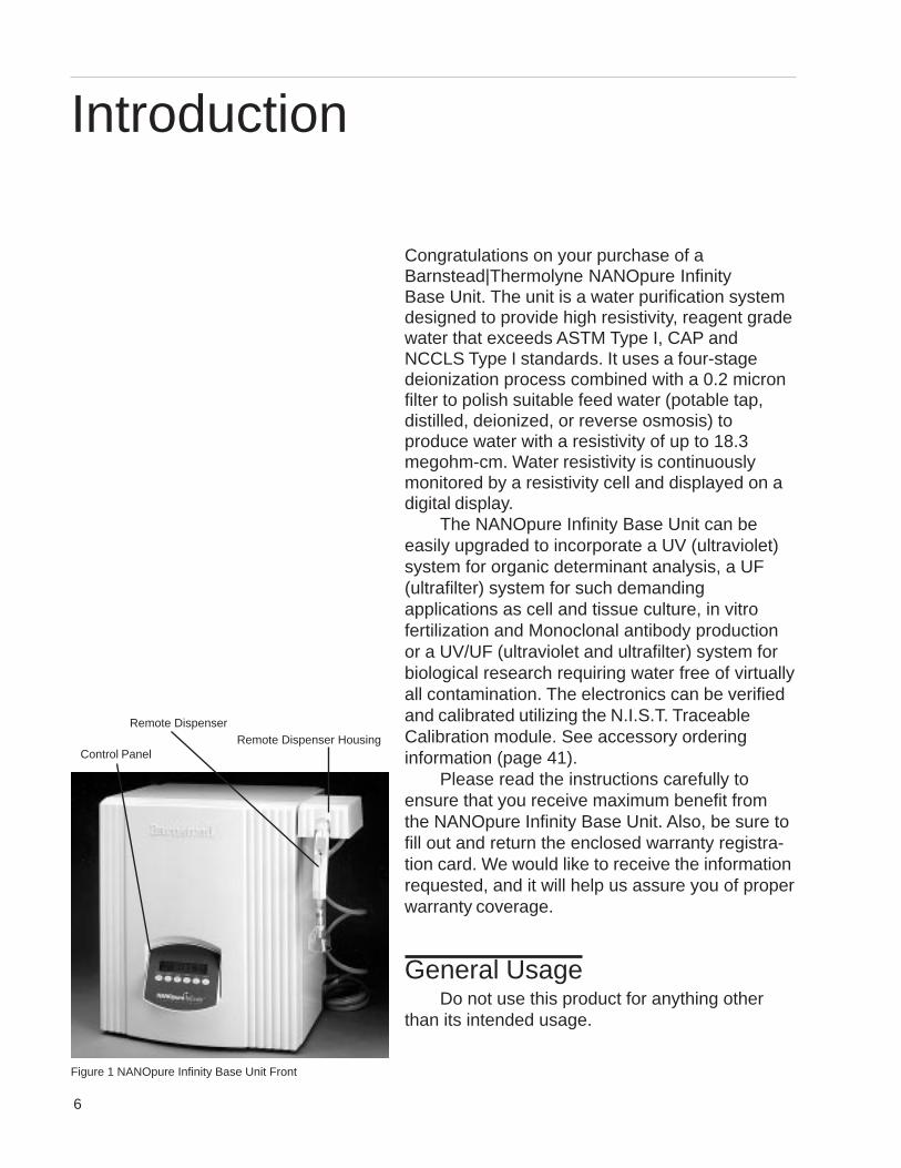
Figure 1 NANOpure Infinity Base Unit Front
Remote DispenserRemote Dispenser Housing
Control Panel
7
Dimensions and Clearance RequirementsDimensions (include remote dispenser housing mounted to unit )
Wall mounted modelsWidth 20” (50.8 cm)Depth 17-1/2” (44.5 cm)Height 34-7/8” (88.6 cm).
Bench mounted modelsWidth 25” (63.5 cm)Depth 17-1/2” (44.5 cm)Height 22-5/8” (57.5 cm)
Dimensions (remote dispenser housing mounted away from unit)Wall and Bench mounted models
Width 20” (50.8 cm)Depth 17-1/2” (44.5 cm)Height 22-5/8” (57.5 cm)
ClearancesSides - 6” (15 cm) minimum for servicing.Above - 3” (7.6 cm) minimum for removal of the outer case.Front - 20” (50.8 cm) minimum for opening the front door.
Cartridge replacement is easily accomplished by opening the front door.
Feed Water RequirementsTypes1 Tap (Potable), RO, DI, distilled.TOC Less than 1.0 ppm.Turbidity 1.0 N.T.U. maximum.Pressure Range Gravity feed to 100 psig (7kg/cm2) maximum.Temperature Range 4.4°C - 48.8°C (40-120°F)
Product WaterWater Quality
Resistivity ASTM, CAP and NCCLS Type ITOC Less than 3.0 ppb
Flow Rate 1.5 lpm maximum at minimum inlet feed water pressure of30 PSIG at 60 HZ and with a new final filter.
Specifications
1Suitability as qualified by laboratory analysis.
8
Electrical RequirementsThe NANOpure Infinity Base Unit is equipped with a power cord to be plugged into anelectrical outlet of the appropriate voltage.Voltage and Frequency (Nominal)Model D8963 100 VAC, 50-60 Hz 85-110 VAC, 47-63 Hz, 1 phaseModel D8961 120 VAC, 50-60 Hz 98-127 VAC, 47-63 Hz, 1 phaseModel D8962-33 230 VAC, 50-60 Hz 220-253 VAC, 47-63 Hz, 1 phase
Environmental ConditionsOperating: 4°C - 49°C; 20% to 80% relative humidity, non-condensing. Installation
Category II (over-voltage) in accordance with IEC 664. Pollution Degree 2 inaccordance with IEC 664. Altitude limit: 3,500 meters.
Storage: -25°C to 65°C; 10% to 85% relative humidity.
Declaration of Conformity (-33 models only)Barnstead|Thermolyne hereby declares under its sole responsibility that this product con-forms with the technical requirements of the following standards:
EMC: EN 50081-1 Generic Emission Standard; EN 50082-1 Generic Immunity Standard;
Safety: IEC 1010-1-92 Safety requirements for electrical equipment for measurement,control, and laboratory use; Part I: General Requirements
per the provisions of the Electromagnetic Compatability Directive 89/336/EEC, as amendedby 92/31/EEC and 93/68/EEC, and per the provisions of the Low Voltage Directive 73/23/EEC, as amended by 93/68/EEC.
The authorized representative located within the European Community is:European ManagerBarnstead|ThermolyneSaarbrückener Str. 248D-38116 BraunschweigGermany
Copies of the Declaration of Conformity are available upon request.
SPECIFICATIONS
9
Unpackaging1. Remove the unit from its shipping
container. Remove all contents carefully.Ensure that the feed tubing,sanitization cartridge, remotedispenser housing and its twobrackets, wall bracket, accessoryparts bag and power cord areremoved from the packagingmaterials before discarding. Put theNANOpure Infinity Base Unit on abench.
Choosing a SiteThe NANOpure Infinity Base Unit systemfeatures a pivoting control panel display and adispenser which allow the system to bemounted almost anywhere within thelaboratory. Use wall bracket for wall mountedsystems as a template to drill mounting holes.(The NANOpure Infinity Base Unit does notinclude screws and fasteners for mounting.)Allow a minimum of 6 inches (15 cm) clearanceon all sides of the unit for servicing, 3 inches(7.6 cm) on top for outer case removal and 20inches (50.8 cm) in front for opening the door.
Unpackaging and InstallationCautionWall composition, conditionand construction, as well asfastener type, must beconsidered when mountingthis unit. The mountingsurface and fastenersselected must be capable ofsupporting a minimum of 275lbs. Inadequate support and/or fasteners may result indamage to mounting surfaceand/or equipment. If you areunsure of mounting surfacecomposition, condition andconstruction or correctfasteners, consult yourbuilding maintenance groupor contractor.
NoteThe outlet of a gravity feedstorage reservoir must be aboveor at the same level as the inletof the NANOpure Infinity BaseUnit.
WarningDo not locate the NANOpureInfinity Base Unit directly overequipment that requires electricalservice. Routine maintenance ofthis unit may involve waterspillage and subsequentelectrical shock hazard ifimproperly located.
Do not use in the presence offlammable or combustiblematerials; fire or explosion mayresult. The device containscomponents which may ignitesuch materials.
10
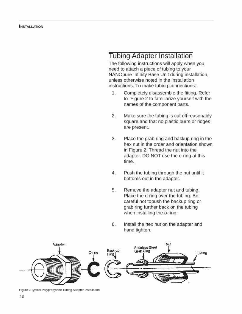
Tubing Adapter InstallationThe following instructions will apply when youneed to attach a piece of tubing to yourNANOpure Infinity Base Unit during installation,unless otherwise noted in the installationinstructions. To make tubing connections:
1. Completely disassemble the fitting. Referto Figure 2 to familiarize yourself with thenames of the component parts.
2. Make sure the tubing is cut off reasonablysquare and that no plastic burrs or ridgesare present.
3. Place the grab ring and backup ring in thehex nut in the order and orientation shownin Figure 2. Thread the nut into theadapter. DO NOT use the o-ring at thistime.
4. Push the tubing through the nut until itbottoms out in the adapter.
5. Remove the adapter nut and tubing.Place the o-ring over the tubing. Becareful not topush the backup ring orgrab ring further back on the tubingwhen installing the o-ring.
6. Install the hex nut on the adapter andhand tighten.
Figure 2 Typical Polypropylene Tubing Adapter Installation
INSTALLATION
11
Remote Dispenser HousingThe Infinity unit comes complete with a remotedispenser allowing you to deliver water up to eightfeet (2.4 meters) away from the unit. Install theremote dispenser housing on the bottom right ofthe unit if wall mounting or top right side of theunit if bench mounting. The dispenser can also beremotely installed up to six feet (1.8 meters) fromthe right hand side of the unit. An accessory partsbag shipped with the unit contains seven holeplugs, six screws (three flat head, three panhead) and one nut. You will also need to find twosmall brackets packed separately in the Infinitybox.
Installing the Remote DispenserHousing on Bench Mounted Units
1. Remove the locking screw located on theright hand side of the Infinity unit betweenthe rails.
2. Line up the two slots on the left side of theremote dispenser housing with the top ofthe two rails on the Infinity unit. Slide theremote dispenser housing down onto therails.
3. Replace the locking screw to secure theremote dispenser housing.
INSTALLATION
12
Installing the Remote DispenserHousing on Wall Mounted UnitsIf you are installing the remote dispenserhousing on a wall mounted unit, remove thetwo rails and locking screw on the right side ofthe Infinity unit. Replace the screws with holeplugs provided. Retain the two rails for possiblefuture use.
Prior to installing the NANOpure InfinityBase Unit on a wall, lay the unit on its back toattach the remote dispenser housing.
1. Remove two screws from the back ofthe remote dispenser housing. Keepthem. You will use them later.
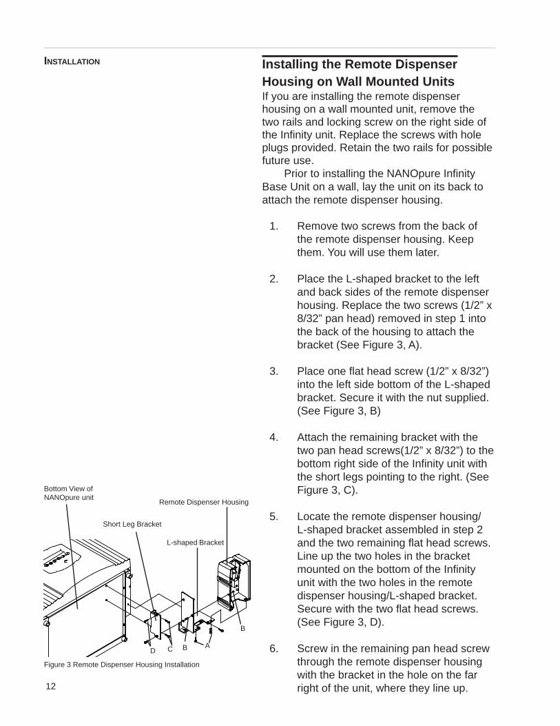
2. Place the L-shaped bracket to the leftand back sides of the remote dispenserhousing. Replace the two screws (1/2” x8/32” pan head) removed in step 1 intothe back of the housing to attach thebracket (See Figure 3, A).
3. Place one flat head screw (1/2” x 8/32”)into the left side bottom of the L-shapedbracket. Secure it with the nut supplied.(See Figure 3, B)
4. Attach the remaining bracket with thetwo pan head screws(1/2” x 8/32”) to thebottom right side of the Infinity unit withthe short legs pointing to the right. (SeeFigure 3, C).
5. Locate the remote dispenser housing/L-shaped bracket assembled in step 2and the two remaining flat head screws.Line up the two holes in the bracketmounted on the bottom of the Infinityunit with the two holes in the remotedispenser housing/L-shaped bracket.Secure with the two flat head screws.(See Figure 3, D).
6. Screw in the remaining pan head screwthrough the remote dispenser housingwith the bracket in the hole on the farright of the unit, where they line up.
INSTALLATION
Figure 3 Remote Dispenser Housing Installation
Remote Dispenser Housing
L-shaped Bracket
Short Leg Bracket
ABD C
Bottom View ofNANOpure unit
B
13
Installing the Remote DispenserHousing in Remote LocationsIf you are installing the remote dispenser housingin a remote location away from the Infinity unit,remove the two rails and locking screw on theright side of the unit. Replace the screws withhole plugs provided. Retain the two rails forpossible future use.
The remote dispenser housing can be in-stalled up to six feet (1.8 meters) away from theunit.
1. Remove the two screws from the back ofthe remote dispenser housing. Keepthem. You will use them later.
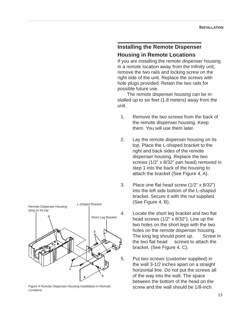
2. Lay the remote dispenser housing on itstop. Place the L-shaped bracket to theright and back sides of the remotedispenser housing. Replace the twoscrews (1/2” x 8/32” pan head) removed instep 1 into the back of the housing toattach the bracket (See Figure 4, A).
3. Place one flat head screw (1/2” x 8/32”)into the left side bottom of the L-shapedbracket. Secure it with the nut supplied.(See Figure 4, B).
4. Locate the short leg bracket and two flathead screws (1/2” x 8/32”). Line up thetwo holes on the short legs with the twoholes on the remote dispenser housing.The long leg should point up. Screw inthe two flat head screws to attach thebracket. (See Figure 4, C).
5. Put two screws (customer supplied) inthe wall 3-1/2 inches apart on a straighthorizontal line. Do not put the screws allof the way into the wall. The spacebetween the bottom of the head on thescrew and the wall should be 1/8-inch.
INSTALLATION
Figure 4 Remote Dispenser Housing Installation in RemoteLocations
Remote Dispenser Housinglying on its top
L-shaped Bracket
Short Leg Bracket
A
B
C
B
14
6. Line up the key hole slots on theremote dispenser housing with the twoscrews in the wall. Slide the remotedispenser housing down onto thescrews.
7. Put two more screws (customersupplied) into the two remaining holes inthe remote dispenser housing to securethe remote dispenser housing bracket tothe wall.
8. Install two hole plugs into the two holesin the side of the bracket.
Lock the dispenser into its housing by placing thetubing end of the dispenser into the U-shapedgroove in the housing and pushing it toward theback of the unit. You know it is locked when youhear a click. After the remote dispenser is fullyinserted into the pivoting holder you must rotatedown.
To remove the dispenser from its housing, lift/rotate up and pull the dispenser straight out.
Other accessoriesOptional accessories for this unit include an inletcell, float switch, low pressure switch and N.I.S.T.Traceable Calibration Module. Installationprocedures for these accessories are explained inlater sections of this manual. It is best to installthese accessories prior to mounting theNANOpure Infinity Base Unit.
Bench Mounting1. Place NANOpure Infinity Base Unit on a
bench top that is accessible to water andelectricity and that is convenient to yourwork area, noting clearance requirements.
INSTALLATION
15
Wall MountingInstall the NANOpure Infinity on a wall in aconvenient location that is accessible to waterand electricity.
1. Locate the wall bracket packedseparately from the unit.
2. Using the wall bracket as a template,locate and drill the mounting holes inthe wall. A minimum of four(customer-supplied) fasteners will berequired — two on the top and two onthe bottom.
3. Attach the wall bracket to the wall usingthe customer-supplied fasteners.
4. Remove the locking screws on eachside of the wall bracket.
5. Pull the two locking slides on each sideof the wall bracket out as far as theywill go.
6. Hang the Infinity unit on the wall bracketby sliding the mounting pins into the wallbracket slots.
7. Push the locking slides on each sideof the wall bracket in as far as they willgo.
8. Replace the locking screws.
CautionWall composition, condition andconstruction, as well as fastenertype, must be considered whenmounting this unit. The mountingsurface and fasteners selectedmust be capable of supporting aminimum of 275 lbs. Inadequatesupport and/or fasteners mayresult in damage to mountingsurface and/or equipment. If youare unsure of mounting surfacecomposition, condition andconstruction or correct fasteners,consult your buildingmaintenance group or contractor.
INSTALLATION
NotePrior to installing the NANOpure Infinity Base Unit on the wall, ensure that theremote dispenser housing and/or other accessories such as the Inlet Cell areinstalled. See the appropriate section of this manual for installation of accessories.
NoteThe outlet of a gravity feedstorage reservoir must be aboveor at the same level as the inletof the NANOpure Infinity BaseUnit.
WarningDo not locate the NANOpureInfinity Base Unit directly overequipment that requires electricalservice. Routine maintenance ofthis unit may involve waterspillage and subsequentelectrical shock hazard ifimproperly located.
Do not use in the presence offlammable or combustiblematerials; fire or explosion mayresult. The device containscomponents which may ignitesuch materials.
16
Water Connections
Feed Water Connection1. Locate the length of 3/8” O.D. tubing
provided with a quick disconnect inserton one end and a 3/8” O.D. X 1/4” NPTtubingadapter on the other.
2. Install the tubing adapter onto yourincoming water line. We recommend acustomer supplied shut off valve beinstalled in your feed water line. Do notconnect the feed water to yourNANOpure Infinity Base Unit. You willconnect this during the initial sanitizationprocedure.
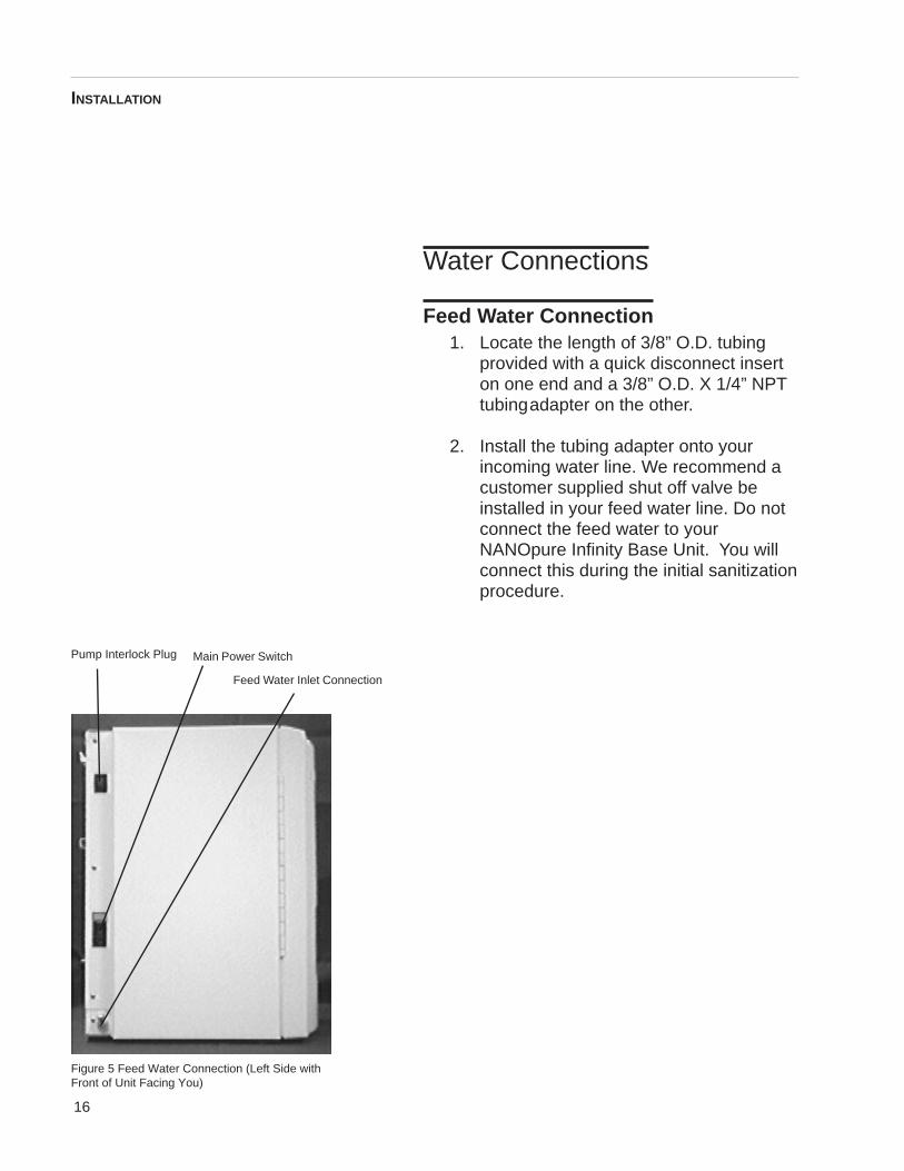
Figure 5 Feed Water Connection (Left Side withFront of Unit Facing You)
Feed Water Inlet Connection
Pump Interlock Plug Main Power Switch
INSTALLATION
17
Familiarize yourself with the controls prior toproceeding. More detailed information isavailable on pages 25-28.
Main Power SwitchThe main power switch on the NANOpureInfinity Base Unit is located on the lower leftside of the unit (as you face the front of theunit), directly above the power cord receptacle.
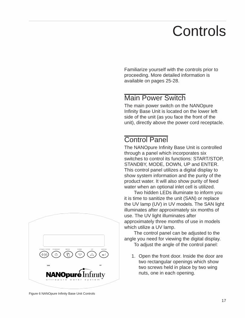
Control PanelThe NANOpure Infinity Base Unit is controlledthrough a panel which incorporates sixswitches to control its functions: START/STOP,STANDBY, MODE, DOWN, UP and ENTER.This control panel utilizes a digital display toshow system information and the purity of theproduct water. It will also show purity of feedwater when an optional inlet cell is utilized.
Two hidden LEDs illuminate to inform youit is time to sanitize the unit (SAN) or replacethe UV lamp (UV) in UV models. The SAN lightilluminates after approximately six months ofuse. The UV light illuminates afterapproximately three months of use in modelswhich utilize a UV lamp.
The control panel can be adjusted to theangle you need for viewing the digital display.
To adjust the angle of the control panel:
1. Open the front door. Inside the door aretwo rectangular openings which showtwo screws held in place by two wingnuts, one in each opening.
UVSAN
START/STOP ENTERDOWN UPMODESTANDBY
Figure 6 NANOpure Infinity Base Unit Controls
Controls
18
2. Turn the wing nuts to the left to unlockand loosen them. The control panel willnow pivot top to bottom in its opening.Reposition the control panel to yourdesired viewing position.
3. Lock the control panel in place by turningthe wing nuts to the right until they arehand-tightened.
SwitchesWhen the main power switch (on the lower leftside of the unit) is on, the six switches on thecontrol panel function as follows:
START/STOP allows you to turn unit on or off.
STANDBY allows you to put the unit into standby,recirculating water for 10 minutes every hour.When in standby, the display shows “StandbyMode” during periods of inactivity. During the 10-minute recirculation, the display reads“Recirculation.”
MODE allows you to change from purity readingto maintenance prompts and activities.
DOWN and UP allow you to scroll betweendifferent commands and values.
ENTER allows you to activate a certain mode.
CONTROLS
19
Initial sanitizationYour NANOpure Infinity Base Unit has beenshipped with a sanitization cartridge (CatalogNo. D50258) that you will install. Three emptycartridges have been installed in the unit,allowing you to sanitize your NANOpure InfinityBase Unit prior to using it for the first time. Tosanitize your NANOpure Infinity Base Unit:
1. Open the front door. Disengage thecartridge hold-down bracket by pulling itout and up. Remove the D50258sanitization cartridge from its bag. Wetthe cartridge o-rings with water. Installthe D50258 sanitization cartridge in theempty cartridge position (#4). Press thetop cartridge nipple into the uppersocket until it bottoms out. Then, lowerthe cartridge inserting the bottomcartridge nipple into the lower socketuntil it is firmly seated. Replace thecartridge hold-down bracket. Close thefront door.
2. Attach the feed water line (from step 2Feed Water Connection, see Figure 5)to the unit by snapping the quickdisconnect coupling into the quickdisconnect body in the lower left side ofthe unit.
3. Plug the power cord into the unit’spower entry module and plug into a liveoutlet. Place the main power switch tothe “I” (on) position. Place a suitablecontainer under the remote dispenser.Depress the trigger to open the remotedispenser. The remote dispenser canbe locked by depressing the button onits right side while depressing thetrigger.
WarningAvoid splashing disinfectingsolutions on clothing or skin.
Ensure all piping connections aretight to avoid leakage.
Ensure adequate ventilation.
Carefully follow manufacturer’ssafety instructions and materialsafety data sheets.
This device is to be used withwater feeds only.
Sanitizing/cleaning agents mustbe used in compliance withinstructions in this manual.Failure to comply with the abovecould result in explosion andpersonal injury.
Use a properly groundedelectrical outlet of correct voltageand current handling capacity.
CautionMake sure the cartridgehold-down bracket is inplace.
Initial Operation
NoteThe top cartridge nipple is theone with the right-angle turn andone flange. The bottom cartridgenipple extends straight out fromthe cartridge.
The flange on the top cartridgenipple should be able to slidedown the keyway wall behind thesheet metal.
20
4. Push the START/STOP switch to start.
5. Run water to drain for 30 seconds, closethe dispenser by depressing the handle.Depressing the handle will unlock thebutton and close the dispenser.
6. Recirculate the water for 30 minutes.
7. After 30 minutes, reset the sanitizationtimer according to the instructions on page27 and then press START/STOPswitch to turn the unit off. Remove thefeed water line. Turn the main powerswitch to “O” position.
8. Open the remote dispenser, lock it openand point it down a drain or into asuitable container. Depressurize theunit until you are no longer gettingwater out of the remote dispenser.
9. Open the front door. Disengage thecartridge hold-down bracket. Remove allof the cartridges by pulling first up andthen out. Drain the water from the threeempty cartridges and keep them for futureuse. Throw away the sanitization cartridge.
10. Proceed to Cartridge Installation andRinse Up.
NoteTo disrupt the flow of waterto the NANOpure InfinityBase Unit, press thestainless steel thumb pad onthe quick disconnect fitting.The insert with the valve iseasily removed. To resupplythe Infinity unit with water,Attach the feed water line(from step 2 Feed WaterConnection) to the unit bysnapping the quickdisconnect coupling into thequick disconnect body in thelower left back of the unit.
NoteProduct purity duringsanitization will be very low.Do not pay close attention tothese readings or below setpoint indication during thesanitization procedure.
WarningDepressurize system prior todisengaging the cartridgehold-down bracket.
INITIAL OPERATION
NoteThe cartridges will stillcontain water whenremoved. Place thecartridges upside down in asink, bucket or otherwaterproof container to drainthem after removal.
21
Cartridge Installationand Rinse Up
1. Open the front door.
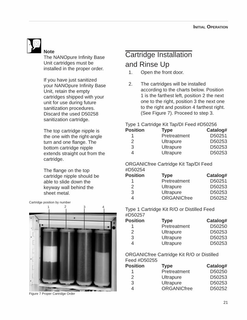
2. The cartridges will be installedaccording to the charts below. Position1 is the farthest left, position 2 the nextone to the right, position 3 the next oneto the right and position 4 farthest right.(See Figure 7). Proceed to step 3.
Type 1 Cartridge Kit Tap/DI Feed #D50256Position Type Catalog#
1 Pretreatment D502512 Ultrapure D502533 Ultrapure D502534 Ultrapure D50253
ORGANICfree Cartridge Kit Tap/DI Feed#D50254Position Type Catalog#
1 Pretreatment D502512 Ultrapure D502533 Ultrapure D502534 ORGANICfree D50252
Type 1 Cartridge Kit R/O or Distilled Feed#D50257Position Type Catalog#
1 Pretreatment D502502 Ultrapure D502533 Ultrapure D502534 Ultrapure D50253
ORGANICfree Cartridge Kit R/O or DistilledFeed #D50255Position Type Catalog#
1 Pretreatment D502502 Ultrapure D502533 Ultrapure D502534 ORGANICfree D50252
NoteThe NANOpure Infinity BaseUnit cartridges must beinstalled in the proper order.
If you have just sanitizedyour NANOpure Infinity BaseUnit, retain the emptycartridges shipped with yourunit for use during futuresanitization procedures.Discard the used D50258sanitization cartridge.
The top cartridge nipple isthe one with the right-angleturn and one flange. Thebottom cartridge nippleextends straight out from thecartridge.
The flange on the topcartridge nipple should beable to slide down thekeyway wall behind thesheet metal.
INITIAL OPERATION
Figure 7 Proper Cartridge Order
1 2 3 4Cartridge position by number
22
3. Remove the protective bag and wetthe o-rings with water on both cartridgenipples.
4. Install the appropriate cartridge incartridge position #1 by pressing thetop cartridge nipple into the uppersocket until it bottoms out.
5. Lower the cartridge and insert thebottom cartridge nipple into the lowersocket until it is firmly seated.
6. Repeat steps 3 - 5 with the remainingcartridges in your kit, placing them inthe next three positions from left toright according to the Cartridge Kitscharts on page 21. Do not install the 0.2micron filter and bell assembly at thistime.
7. Replace the cartridge hold-down bracket.
8. Close the front door.
9. Reattach the feed water line to the unitby snapping the quick disconnectcoupling into the quick disconnect bodyin the lower left back of the unit.
10. Turn the unit on by turning the mainpower switch to the “I” (on) position.
11. Point the outlet of the remotedispenser down a drain or into a suitablecontainer. Depress the draw-off triggerand lock it open.
12. Press the START/STOP switch to start.
Caution Make sure the cartridgehold-down bracket is inplace.
CautionDo not allow the NANOpureInfinity Base Unit to operateunless water is available tothe unit.
INITIAL OPERATION
NoteEnsure both o-rings of thecartridge are down inside theconnector before movingonto the next cartridgeinstallation.
23
13. Run product water to drain for 5minutes through the remote dispenser.Close the remote dispenser and let thewater recirculate until the resistivityreaches your desired purity level. (Seenote on this page).
14. Remove a new 0.2 micron filter andbell assembly from its bag and insert itinto the Luer fitting on the remotedispenser. Gently turn it clockwise untilit is fully seated in the Luer fitting.
15. Remove the protective cap from thefilter bell. Open the remote dispenserand flush 1-2 liters of water throughthe 0.2 micron filter. The product wateris now ready for use. (See note on thispage).
INITIAL OPERATION
NoteFor more demandingapplications where low TOCwater is required, a rinse of15-20 liters through thecartridges and filter may benecessary.
CautionDo not overtighten the 0.2micron filter assembly ontothe Luer fitting or useexcessive force in seating it.The filter and/or Luer fittingcan be damaged byovertightening or excessiveforce.
24
1. Turn the system power on by depressingthe main power switch to the I position.
2. Press the START/STOP switch on thecontrol panel.
3. The system greeting lights indicatewhich module, if any, is installed on thebase unit. This greeting is one of thefollowing: “NANOPURE”, “NANOPUREUV”, “NANOPURE UF”, or “NANOPUREUV/UF”. Your base unit can be upgradedto include any of the three modules: UV module (Catalog No. D8974), UF module (D8984) or UV/UF module (D8994).
While the system greeting is displayedfor approximately five seconds, the unitchecks for the presence of an inlet cell.
4. The system electronics will check itscalibration. (All units have been factorycalibrated.) If calibration is OK thedisplay will show “Calibration OK.” Afterthis it will show “Prod. .... MΩ-cm”. Thenthe display will read “Prod. 10 (±0.2) MΩ-cm.” This is a reading of the calibrationreference value.
5. The display will then begin readingresistivity of the product water. Initially itwill read “Prod. .... MΩ-cm” until the air isbled from the system.
6. Allow the water’s resistivity to rise to thedesired purity before drawing off water.
7. The system should be left on or instandby during the work day. (See Useof Standby mode.)
NoteOn initial start-up, the puritymeter may display "Prod. ....MΩ-cm". This is caused byair in the cell and should bereplaced by a resistivityreading almost immediately.If the dots aren’t replaced bya value after one minute,refer to the Problem Solv-ing section for this manual.
Normal Operation
25
Remote Dispenser OperationLock the dispenser into its housing by placing thetubing end of the dispenser into the U-shapedgroove in the housing and pushing it toward theback of the unit until it stops and then pull down.You know it is locked when you hear a click.
To operate:
1. Remove the protective cap from the filterbell.
2. Depress the draw-off trigger.
3. When draw off is complete, release thedraw-off trigger and replace theprotective cap on the filter bell.
4. For unattended operation, depress thebutton on right side of the dispenser at thesame time as the trigger is depressed.
5. To unlock the draw-off trigger and stopdispensing water, press the draw-offtrigger.
To remove the dispenser from its housing, pull itup and out. See page 14 for additional informa-tion.
Use of Standby Mode
At the end of the work day, press the Standbyswitch on the front of the NANOpure Infinity BaseUnit to place the unit in Standby mode for thenight. Press the STANDBY switch and the displaywill read “Standby Mode” for 50 minutes and thengo into a 10-minute recirculation mode. While thepump is energized, the display will read“Recirculation.”
NoteDo not turn off theNANOpure Infinity Base Unitduring non-work hours.Doing so will allow bacterialgrowth and othercontamination of the water inthe system. As a result, thesystem will require a lengthyrinse-up period at thebeginning of the work day toachieve high-quality productwater. We recommend usingthe Standby Mode.
NORMAL OPERATION
26
Selecting the Set PointThe NANOpure Infinity Base Unit electronicsinclude a user programmable set point whichalerts you when water quality falls below theprogrammed set point. The set point is userselectable from 0-18 MΩ-cm. The display willalternate actual resistivity measurements with a“Below Setpoint” message when themeasurement is below the set point.
The set point indication is set at the factory at 10MΩ-cm.
You must start this procedure from the off (stop)position.
1. Press and hold the ENTER switch.
2. Press the START/STOP switch.
3. Release switches.
4. The display will read “Setpt. 10 MΩ-cm”.
5. To adjust the value, press the UP orDOWN arrow until your desired value isdisplayed and press ENTER.
If the resistivity of the product water falls belowthe set point value, the display will read theresistivity value for approximately seven secondsand a “Below Setpoint” display for approximatelythree seconds. Once the resistivity value risesabove the set point, the unit will only readresistivity.
NORMAL OPERATION
27
Resetting the Sanitization Timer1. While the NANOpure Infinity is
operating, press the MODE switch.
2. The display will read “Reset SAN Timer”
3. Press the ENTER switch to reset theSanitization Timer.
4. The display will read “Enter to Reset”
5. Press the ENTER switch again and thetimer will be reset. This will reset thesanitization timer for six months.
Reading Purity of ProductWater and Feed WaterWith Optional Inlet CellAccessory
1. Turn the system power on by depressingthe main power switch to the I position.
2. Press the START/STOP switch on thecontrol panel.
3. The display will show the type of systemfor approximately five seconds.
4. The system electronics will check itscalibration. All units have been factorycalibrated. If calibration is OK thedisplay will show “Calibration OK.” Afterthis it will show “Prod. .... MΩ-cm”. Thenthe display will read “PROD. 10 (±0.2)MΩ-cm.” This is a reading of thecalibration reference value.
NotePress the ENTER button atany step and the unit will goto resistivity of the productwater. Pressing the UP andDOWN switches allowsscrolling between the variouspurity of product water andfeed water displays.
NORMAL OPERATION
28
5. The display will then begin readingresistivity of the product water. Initially itwill read “Prod. .... MΩ-cm” until the air isbled from the system.
6. Press the DOWN switch to:Display conductivity of product waterDisplay Total Dissolved Solids of
product waterDisplay temperature of product water
7. If no inlet cell is used, the reading willreturn to the resistivity of theproduct water. If an inlet cell is attached,it will read the following:
Display resistivity of inlet waterDisplay conductivity of inlet waterDisplay Total Dissolved Solids of inlet
waterDisplay temperature of inlet waterDisplay resistivity of product water
NORMAL OPERATION
29
Accessories D8964 (float switch) and D2706(pressure switch) are designed to protect theNANOpure Infinity Base Unit pump by alertingthe NANOpure Infinity Base Unit of aninadequate feed water condition so that thepump can be shut down. If an inadequate feedwater condition exists and the NANOpureInfinity Base Unit pump is shut down due to thiscondition, the display will read “Check Inlet.”Use the following instructions for installation.
1. Disconnect the unit from the electricalpower.
2. If using D8964 float switch, follow theinstallation instructions included with thefloat switch for installation into a tank.
3. If using D2706 low pressure switch,install the PVC tee (supplied withD2706) in incoming water line. Screwthe switch into the top of the tee, thenconnect the inlet tubing to theNANOpure Infinity Base Unitwith the remaining opening.
4. Route the cable from the float or lowpressure switch to the top left of theNANOpure Infinity Base Unit.
5. Remove the jumper plug from the back,left, upper portion of the unit and savefor future use.
6. Plug the cable into the jumper plugoutlet.
7. Reconnect the electrical power.
WarningDisconnect from the powersupply prior to maintenanceand servicing.
Installing Float or PressureSwitch
30
The NANOpure Infinity Base Unit system offers,as an optional feature, the ability to monitor theresistivity of the NANOpure Infinity Base Unit inletwater.
To install the inlet cell:
1. Disconnect inlet water and electricalservice to unit. Open Remote Dispenser todepressurizeunit.
2. Open the front door.
3. Remove the screws holding the Infinityunit’s case in place. As the unit faces you,there are three screws in the left side nearthe back, three in the right side near theback and five in front, two on each sideand one above the cartidge hold-downbracket. Remove the jumper plug, FloatSwitch or Pressure Switch Cable from theback, left, upper portion of the unit.
4. Remove the remote dispenser from itshousing.
5. Lift up to remove the outer case.
6. Remove the electric section cover directlybehind the cartridges.
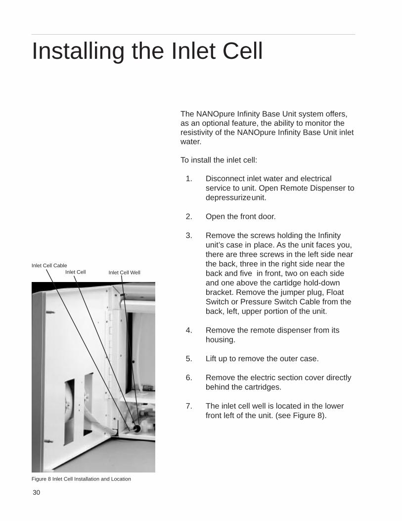
7. The inlet cell well is located in the lowerfront left of the unit. (see Figure 8).
Installing the Inlet Cell
Figure 8 Inlet Cell Installation and Location
Inlet Cell CableInlet Cell Inlet Cell Well
31
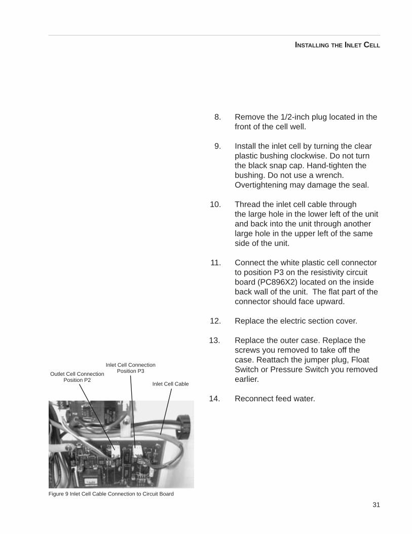
Figure 9 Inlet Cell Cable Connection to Circuit Board
Inlet Cell Cable
8. Remove the 1/2-inch plug located in thefront of the cell well.
9. Install the inlet cell by turning the clearplastic bushing clockwise. Do not turnthe black snap cap. Hand-tighten thebushing. Do not use a wrench.Overtightening may damage the seal.
10. Thread the inlet cell cable throughthe large hole in the lower left of the unitand back into the unit through anotherlarge hole in the upper left of the sameside of the unit.
11. Connect the white plastic cell connectorto position P3 on the resistivity circuitboard (PC896X2) located on the insideback wall of the unit. The flat part of theconnector should face upward.
12. Replace the electric section cover.
13. Replace the outer case. Replace thescrews you removed to take off thecase. Reattach the jumper plug, FloatSwitch or Pressure Switch you removedearlier.
14. Reconnect feed water.
INSTALLING THE INLET CELL
Outlet Cell ConnectionPosition P2
Inlet Cell ConnectionPosition P3
32
Performing an ElectronicCalibration Using the OptionalN.I.S.T. Calibration Module
If you purchased the optional N.I.S.T. calibrationmodule (Catalog No. E896X5) you can perform acalibration of the NANOpure Infinity purity sensingelectronics traceable to N.I.S.T. standards.
1. Disconnect electrical service to the unit.Open the remote dispenser todepressurize the unit.
2. Open the front door.
3. Remove the screws that hold theInfinity unit’s outer case in place. As youface the unit, there are three screws in theleft side near the back, three in the rightside near the back and five in the front,two on each side and one above thecartridge hold-down bracket. Remove thejumper plug or float/pressure switch fromthe back, left, upper portion of the unit.
4. Remove the remote dispenser from itshousing.
5. Lift and remove the outer case.
6. Remove the electric section cover directlybehind the cartridges.
7. Locate the outlet cell connection on thecircuit board (see figure 9) and removethe outlet cell connection.
N.I.S.T. Calibration Module
33
8. Connect the N.I.S.T. calibration moduleto the connection point (J2), “To OutletCell” on the calibration board(PC896X3A).
9. Replace the electric section coverremoved in step 6.
10. Plug the unit into a live outlet and turnthe unit on by depressing the mainpower switch.
11. Press and hold the DOWN switch on thecontrols.
12. Press the START/STOP switch.
13. Release switches.
14. The display will show “Calibrate?”, pressENTER.
15. Display will read “Calibrating”. When thecalibration is complete the display willshow “Calibration Done”.
16. Turn the main power switch to the “O”(off) position. Unplug the unit.
17. Remove the calibration module andreconnect the cell.
18. Replace the outer case. Replace thescrews you removed earlier. Reattachthe jumper plug or float/pressure switchyou removed earlier.
NoteThe calibration module canbe returned toBarnstead|Thermolyne forrecertification. PleasecontactBarnstead|Thermolyne forinstructions.
N.I.S.T. CALIBRATION MODULE
34
System Sanitization andCartridge ReplacementThe frequency with which you will need to cleanyour unit and replace your cartridges isdependent on your feed water’s characteristics,your purity requirements and your usage. Sanitizeyour NANOpure Infinity Base Unit and replace thecartridges when the product water purity dropsbelow acceptable levels of resistivity, whenorganic levels become too high, or if a new 0.2micron filter clogs rapidly after installation eventhough the cartridges were thoroughly rinsedbefore the 0.2 micron filter was installed. Tosanitize the NANOpure Infinity Base Unit, thepurification cartridges must be replaced with asanitization cartridge and the three emptycartridges supplied with your unit. The simple-to-use sanitization cartridge is available fromBarnsteadlThermolyne (Catalog NumberD50258). This is used in addition to the emptycartridges included with this unit to effect acomplete sanitization.
1. Disconnect electrical service to the unit.
2. Remove the feed water line bydepressing stainless steel thumb pad.
3. Depressurize system by opening theremote dispenser.
4. Open the front door.
5. Be aware that the exhausted cartridge willcontain a cartridge bed of excess water,you will want to have a container availableto place it in after removal.
6. Disengage the cartridge hold-downbracket.
Note The Sanitization Timer willilluminate after six months,reminding you to sanitize theunit. Complete the systemsanitization procedure andreset the sanitization lamp/indicator by going throughthe Reset Sanitization Timerprocedure on page 27.
WarningDisconnect from the powersupply prior to maintenanceand servicing.
NoteThe cartridges will stillcontain a cartridge bed ofwater when removed.Therefore, you will want tohave a sink, bucket or otherwaterproof containeravailable to place them inafter removal.
WarningDepressurize systemcompletely prior to liftingcartridge hold-down bracketand removing cartridges.
Maintenance and Servicing
35
7. Remove the exhausted cartridge in theright-hand (#4) position by pulling it firstup and then out.
8. Remove a D50258 sanitizationcartridge from its packaging. Press thetop cartridge nipple of the D50258sanitization cartridge into the uppersocket in the right-hand (4) position untilit bottoms out.
9. Lower the cartridge and insert thebottom cartridge nipple into the lowersocket until it is firmly seated.
10. Install the three empty cartridgessupplied with your NANOpure InfinityBase Unit in positions 1, 2 & 3.
11. Reposition the cartridge hold-downbracket.
12. Close the front door. Remove the 0.2micron filter and bell assembly.
13. Sanitize, install new cartridges and rinseaccording to the instructions for InitialSanitization and Cartridge Installationin the Initial Operation section.
General Cleaning InstructionsDisconnect electrical service to the unit.
Wipe exterior surfaces with lightly dampenedcloth containing mild soap solution.
NoteThe flange on the topcartridge nipple should beable to slide down thekeyway wall behind thesheet metal.
MAINTENANCE AND SERVICING
36
0.2 Micron Filter ReplacementReplace the 0.2 micron final filter whenever anyof the following conditions occur: every 30days, the product water flow rate is reduced orbacteria break through. The 0.2 micron filter isshipped assembled with a bell. To replace the0.2 micron filter assembly:
1. Remove the old 0.2 micron filterassembly by turning it counterclockwiseuntil it is free from the Luer fitting.
2. Remove the new 0.2 micron filterassembly from its bag and insert it intothe Luer fitting. Gently turn it clockwiseuntil it is fully seated in the Luer fitting.
3. Rinse 1-2 liters of water through thefilter to drain prior to using the productwater.
Fuse Replacement1. Turn off the NANOpure Infinity Base
Unit and disconnect it from the powersupply by removing the power corddirectly below the main power switch.Locate the fuse drawer above the powercord receptacle.
2. Pull out the fuse drawer located in thepower entry module.
3. Remove old fuses and replace withfuses of the same type and rating. (SeeParts Listing.)
4. Replace fuse drawer.
CautionDo not overtighten the 0.2micron filter assembly ontothe Luer fitting or useexcessive force in seating it.The filter and/or Luer fittingcan be damaged byovertightening or excessiveforce.
NoteIf a newly installed 0.2micron filter clogs rapidlyafter installation, theNANOpure Infinity Base Unitmay need to be sanitized toremove bacterialcontaminants. See SystemSanitization.
MAINTENANCE AND SERVICING
Warning Replace fuses with those ofthe same type and rating.
37
5. Reattach the power cord andreconnect the unit to the power supply.
6. Operate normally.
Shutdown
If the NANOpure Infinity Base Unit is to be shutdown for an extended period of time, the unitshould be completely drained and the cartridgesremoved to prevent the growth of bacteria.
If the system has remained inactive and full ofwater for more than 96 hours, the unit should bedrained, sanitized and new cartridges installedprior to use.
MAINTENANCE AND SERVICING
38
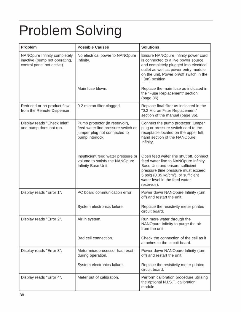
melborP sesuaCelbissoP snoituloS
yletelpmocytinifnIerupONAN,gnitarepotonpmup(evitcani
.)evitcatonlenaplortnoc
erupONANotrewoplacirtceleoN.ytinifnI
.nwolbesufniaM
drocrewopytinifnIerupONANerusnEecruosrewopevilaotdetcennocsi
lacirtceleotnideggulpyletelpmocdnaeludomyrtnerewopsallewsateltuoehtnihctiwsffo/norewoP.tinuehtno
.noitisop)no(I
nidetacidnisaesufniamehtecalpeRnoitces"tnemecalpeResuF"eht
.)63egap(
wolftcudorponrodecudeR.resnepsiDetomeRehtmorf
.deggolcretlifnorcim2.0 ehtnidetacidnisaretliflanifecalpeR"tnemecalpeRretliFnorciM2.0".)63egap(launamehtfonoitces
"telnIkcehC"sdaeryalpsiD.nurtonseodpmupdna
,)riovreserni(rotcetorppmuProhctiwserusserpenilretawdeef
otdetcennoctongulprepmuj.kcolretnipmup
roerusserpretawdeeftneiciffusnIerupONANehtyfsitasotemulov
.tinUesaBytinifnI
repmuj,rotcetorppmupehttcennoCehtotdrochctiwserusserprogulp
tfelreppuehtnodetacolelcatpecererupONANehtfonoitcesdnah
.ytinifnI
tcennoc,ffotuhsenilretawdeefnepOytinifnIerupONANotenilretawdeef
tneiciffuserusnednatinUesaBdeecxetsumerusserpenil(erusserp
mc/gk53.0(gisp5 2 tneiciffusro,)retawdeefehtnilevelretaw
.)riovreser
."1rorrE"sdaeryalpsiD .rorrenoitacinummocdraobCP
.eruliafscinortcelemetsyS
nrut(ytinifnIerupONANnwodrewoP.tinuehttratserdna)ffo
detnirpretemytivitsiserehtecalpeR.draobtiucric
."2rorrE"sdaeryalpsiD .metsysniriA
.noitcennocllecdaB
ehthguorhtretaweromnuRriaehtegrupotytinifnIerupONAN
.tinuehtmorf
tisallecehtfonoitcennocehtkcehC.draobtiucricehtotsehcatta
."3rorrE"sdaeryalpsiD tesersahrossecorporcimreteM.noitarepognirud
.eruliafscinortcelemetsyS
nrut(ytinifnIerupONANnwodrewoP.tinuehttratserdna)ffo
detnirpretemytivitsiserehtecalpeR.draobtiucric
."4rorrE"sdaeryalpsiD .noitarbilacfotuoreteM gnizilituerudecorpnoitarbilacmrofrePnoitarbilac.T.S.I.Nlanoitpoeht
.eludom
Problem Solving
39
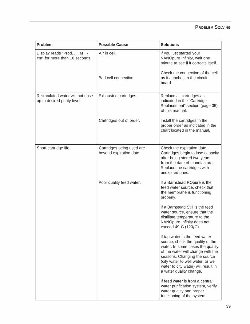
melborP esuaCelbissoP snoituloS
-M.....dorP"sdaeryalpsiD.sdnoces01nahteromrof"mc
.llecniriA
.noitcennocllecdaB
ruoydetratstsujuoyfIenotiaw,ytinifnIerupONAN
.flestistcerroctifieesotetunim
llecehtfonoitcennocehtkcehCtiucricehtotsehcattatisa
.draob
esnirtonlliwretawdetalucriceR.levelytirupderisedotpu
.segdirtracdetsuahxE
.redrofotuosegdirtraC
sasegdirtracllaecalpeRegdirtraC"ehtnidetacidni
)53egap(noitces"tnemecalpeR.launamsihtfo
ehtnisegdirtracehtllatsnIehtnidetacidnisaredroreporp
.launamehtnidetacoltrahc
.efilegdirtractrohS eradesugniebsegdirtraC.etadnoitaripxednoyeb
.retawdeefytilauqrooP
.etadnoitaripxeehtkcehCyticapacesolotnigebsegdirtraC
sraeyowtderotsgniebretfa.erutcafunamfoetadehtmorf
htiwsegdirtracehtecalpeR.senoderipxenu
ehtsierupORdaetsnraBafItahtkcehc,ecruosretawdeef
gninoitcnufsienarbmemeht.ylreporp
deefehtsillitSdaetsnraBafIehttahterusne,ecruosretaw
ehtoterutarepmetetallitsidtonseodytinifnIerupONAN
.)C¡021(C¡94deecxe
retawdeefehtsiretawpatfIehtfoytilauqehtkcehc,ecruos
ytilauqehtsesacemosnI.retawehthtiwegnahclliwretawehtfo
ecruosehtgnignahC.snosaesllewro,retawllewotretawytic(nitluserlliw)retawyticotretaw
.egnahcytilauqretawa
lartnecamorfsiretawdeeffIyfirev,metsysnoitacifirupretaw
reporpdnaytilauqretaw.metsysehtfogninoitcnuf
PROBLEM SOLVING
40
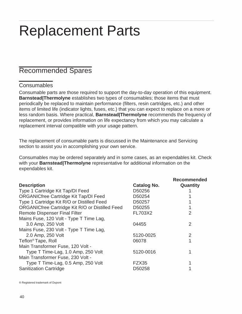
Recommended Spares
ConsumablesConsumable parts are those required to support the day-to-day operation of this equipment.Barnstead|Thermolyne establishes two types of consumables; those items that mustperiodically be replaced to maintain performance (filters, resin cartridges, etc.) and otheritems of limited life (indicator lights, fuses, etc.) that you can expect to replace on a more orless random basis. Where practical, Barnstead|Thermolyne recommends the frequency ofreplacement, or provides information on life expectancy from which you may calculate areplacement interval compatible with your usage pattern.
The replacement of consumable parts is discussed in the Maintenance and Servicingsection to assist you in accomplishing your own service.
Consumables may be ordered separately and in some cases, as an expendables kit. Checkwith your Barnstead|Thermolyne representative for additional information on theexpendables kit.
RecommendedDescription Catalog No. QuantityType 1 Cartridge Kit Tap/DI Feed D50256 1ORGANICfree Cartridge Kit Tap/DI Feed D50254 1Type 1 Cartridge Kit R/O or Distilled Feed D50257 1ORGANICfree Cartridge Kit R/O or Distilled Feed D50255 1Remote Dispenser Final Filter FL703X2 2Mains Fuse, 120 Volt - Type T Time Lag,
3.0 Amp, 250 Volt 04455 2Mains Fuse, 230 Volt - Type T Time Lag,
2.0 Amp, 250 Volt 5120-0025 2Teflon® Tape, Roll 06078 1Main Transformer Fuse, 120 Volt -
Type T Time-Lag, 1.0 Amp, 250 Volt 5120-0016 1Main Transformer Fuse, 230 Volt -
Type T Time-Lag, 0.5 Amp, 250 Volt FZX35 1Sanitization Cartridge D50258 1
Replacement Parts
® Registered trademark of Dupont
41
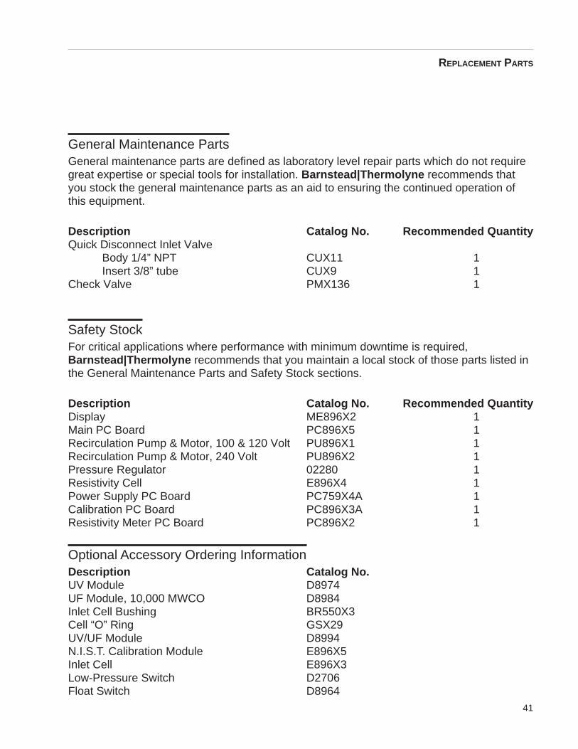
General Maintenance PartsGeneral maintenance parts are defined as laboratory level repair parts which do not requiregreat expertise or special tools for installation. Barnstead|Thermolyne recommends thatyou stock the general maintenance parts as an aid to ensuring the continued operation ofthis equipment.
Description Catalog No. Recommended QuantityQuick Disconnect Inlet Valve
Body 1/4” NPT CUX11 1Insert 3/8” tube CUX9 1
Check Valve PMX136 1
Safety StockFor critical applications where performance with minimum downtime is required,Barnstead|Thermolyne recommends that you maintain a local stock of those parts listed inthe General Maintenance Parts and Safety Stock sections.
Description Catalog No. Recommended QuantityDisplay ME896X2 1Main PC Board PC896X5 1Recirculation Pump & Motor, 100 & 120 Volt PU896X1 1Recirculation Pump & Motor, 240 Volt PU896X2 1Pressure Regulator 02280 1Resistivity Cell E896X4 1Power Supply PC Board PC759X4A 1Calibration PC Board PC896X3A 1Resistivity Meter PC Board PC896X2 1
Optional Accessory Ordering InformationDescription Catalog No.UV Module D8974UF Module, 10,000 MWCO D8984Inlet Cell Bushing BR550X3Cell “O” Ring GSX29UV/UF Module D8994N.I.S.T. Calibration Module E896X5Inlet Cell E896X3Low-Pressure Switch D2706Float Switch D8964
REPLACEMENT PARTS
42
Ordering Procedures
Please refer to the Specification Plate for the complete model number, serial number, andseries number when requesting service, replacement parts or in any correspondenceconcerning this unit.
All parts listed herein may be ordered from the Barnstead|Thermolyne dealer fromwhom you purchased this unit or can be obtained promptly from the factory. When service orreplacement parts are needed we ask that you check first with your dealer. If the dealercannot handle your request, then contact our Customer Service Department at 319-556-2241 or 800-553-0039.
Prior to returning any materials to Barnstead|Thermolyne Corp ., please contact ourCustomer Service Department for a “Return Goods Authorization” number (RGA). Materialreturned without a RGA number will be refused.
43
Two Year Limited Warranty
Barnstead|Thermolyne Corporation warrants that if a product manufactured byBarnstead|Thermolyne and sold within the continental United States or Canada proves tobe defective in material or construction, Barnstead|Thermolyne will provide you, withoutcharge, for a period of ninety (90) days, the labor, and a period of two (2) years, the parts,necessary to remedy any such defect. Outside the continental United States and Canada,the warranty provides, for two (2) years, the parts necessary to remedy any such defect. Thewarranty period shall commence either six (6) months following the date the product is soldby Barnstead|Thermolyne or on the date it is purchased by the original retail consumer,whichever date occurs first.
All warranty inspections and repairs must be performed by and parts obtained froman authorized Barnstead|Thermolyne dealer or Barnstead|Thermolyne (at its owndiscretion). Heating elements, however, because of their susceptibility to overheating andcontamination, must be returned to our factory, and if, upon inspection, it is concluded thatfailure is not due to excessive high temperature or contamination, warranty replacement willbe provided by Barnstead|Thermolyne . The name of the authorizedBarnstead|Thermolyne dealer nearest you may be obtained by calling 1-800-446-6060 orwriting to:
Barnstead|ThermolyneP.O. Box 797
2555 Kerper BoulevardDubuque, IA 52004-0797
USAFAX: (319) 589-0516
E-Mail: [email protected]|Thermolyne’s sole obligation with respect to its product shall be to repair
or replace the product. Under no circumstances shall it be liable for incidental orconsequential damage.
THE WARRANTY STATED HEREIN IS THE SOLE WARRANTY APPLICABLE TOBarnstead|Thermolyne PRODUCTS. Barnstead|Thermolyne EXPRESSLY DISCLAIMSANY AND ALL OTHER WARRANTIES, EXPRESSED OR IMPLIED, INCLUDINGWARRANTIES OF MERCHANTABILITY OR FITNESS FOR USE.

44
Barnstead Thermolyne2555 Kerper Blvd.P.O. Box 797Dubuque, IA 52004-0797 USAPHONE: 319-556-2241 • 800-553-0039FAX: 319-589-0516E-Mail: [email protected]
a subsidiary of