Embed Size (px)
Citation preview
Narrated Guided Tour Following and
Interpretation by an Autonomous Wheelchair
by
Sachithra Madhawa Hemachandra
Submitted to the Department ofElectrical Engineering and Computer Science
in partial fulfillment of the requirements for the degree of
Master of Science in Computer Science and Engineering
at the
MASSACHUSETTS INSTITUTE OF TECHNOLOGY
June 2010
c© Massachusetts Institute of Technology 2010. All rights reserved.
Author . . . . . . . . . . . . . . . . . . . . . . . . . . . . . . . . . . . . . . . . . . . . . . . . . . . . . . . . . . . . . .Department of
Electrical Engineering and Computer ScienceMay 21, 2010
Certified by. . . . . . . . . . . . . . . . . . . . . . . . . . . . . . . . . . . . . . . . . . . . . . . . . . . . . . . . . .Seth Teller
Professor, MIT EECSThesis Supervisor
Accepted by . . . . . . . . . . . . . . . . . . . . . . . . . . . . . . . . . . . . . . . . . . . . . . . . . . . . . . . . .Terry P. Orlando
Chairman, Department Committee on Graduate Theses

2

Narrated Guided Tour Following and Interpretation by an
Autonomous Wheelchair
by
Sachithra Madhawa Hemachandra
Submitted to the Department ofElectrical Engineering and Computer Scienceon May 21, 2010, in partial fulfillment of the
requirements for the degree ofMaster of Science in Computer Science and Engineering
Abstract
This work addresses the fundamental problem of how a robot acquires local knowl-edge about its environment. The domain that we are concerned with is a speech-commandable robotic wheelchair operating in a home/special care environment, ca-pable of navigating autonomously to a verbally-specified location in the environment.We address this problem by incorporating a narrated guided tour following capabilityinto the autonomous wheelchair. In our method, a human gives a narrated guidedtour through the environment, while the wheelchair follows. The guide carries outa continuous dialogue with the wheelchair, describing the names of the salient loca-tions in and around his/her immediate vicinity. The wheelchair constructs a metricalmap of the environment, and based on the spatial structure and the locations of thedescribed places, segments the map into a topological representation with correspond-ing tagged locations. This representation of the environment allows the wheelchairto interpret and implement high-level navigation commands issued by the user. Toachieve this capability, our system consists of an autonomous wheelchair, a person-following module allowing the wheelchair to track and follow the tour guide as s/heconducts the tour, a simultaneous localization and mapping module to construct themetric gridmap, a spoken dialogue manager to acquire semantic information aboutthe environment, a map segmentation module to bind the metrical and topologicalrepresentations and to relate tagged locations to relevant nodes, and a navigationmodule to utilize these representations to provide speech-commandable autonomousnavigation.
Thesis Supervisor: Seth TellerTitle: Professor, MIT EECS
3

4

Acknowledgments
I would like to thank my advisor Prof. Seth Teller for his invaluable guidance, advice
and support during the past two years. I would also like to thank Prof. Nicholas
Roy for his advice and direction both in my involvement in the TBH project and
in the development of the narrated guided tour. I would like to thank Tom Kollar
for his map partitioning system which has formed the basic of the map segmentation
module in the tour guide system as well as for all his helpful ideas and comments.
My thanks to Dr. Michael Mason for his speech activity detection work as well as
the ideas relating to speech recognition with regard to the dialogue manager, Abe
Bachrach for the iSAM-SLAM module that is used for our real-time SLAM module
and William Li for his help in collecting data. Thanks also to everyone else in the
TBH group for all the help on data collection as well as everyone at TBH especially
Don Fredett for all his support. Last but not least I would like to thank my family
and friends for all their moral support.
5

6

Contents
1 Introduction 15
1.1 Problem Description . . . . . . . . . . . . . . . . . . . . . . . . . . . 16
1.2 Motivation . . . . . . . . . . . . . . . . . . . . . . . . . . . . . . . . . 18
1.3 Thesis Overview . . . . . . . . . . . . . . . . . . . . . . . . . . . . . . 19
2 Background and Related Work 21
2.1 Background . . . . . . . . . . . . . . . . . . . . . . . . . . . . . . . . 21
2.2 Related Work . . . . . . . . . . . . . . . . . . . . . . . . . . . . . . . 23
3 Speech-Commandable Autonomous Wheelchair 25
3.1 Wheelchair Platform . . . . . . . . . . . . . . . . . . . . . . . . . . . 25
3.2 Sensors . . . . . . . . . . . . . . . . . . . . . . . . . . . . . . . . . . . 26
3.2.1 Laser Range Scanners . . . . . . . . . . . . . . . . . . . . . . 26
3.2.2 Wheel encoders . . . . . . . . . . . . . . . . . . . . . . . . . . 27
3.2.3 Bluetooth Microphone . . . . . . . . . . . . . . . . . . . . . . 27
3.3 Autonomous Actuators . . . . . . . . . . . . . . . . . . . . . . . . . . 27
3.4 Intelligence . . . . . . . . . . . . . . . . . . . . . . . . . . . . . . . . 28
3.4.1 On-board Computer . . . . . . . . . . . . . . . . . . . . . . . 28
3.4.2 Lightweight Communications and Marshalling . . . . . . . . . 28
3.4.3 Modified CARMEN Robotics Platform . . . . . . . . . . . . . 29
3.5 Dialog Management . . . . . . . . . . . . . . . . . . . . . . . . . . . . 30
3.5.1 Speech Recognizer . . . . . . . . . . . . . . . . . . . . . . . . 30
3.5.2 Speech Synthesizer . . . . . . . . . . . . . . . . . . . . . . . . 30
7

3.5.3 Navigation Mode . . . . . . . . . . . . . . . . . . . . . . . . . 30
3.5.4 Speech Recognition Grammar . . . . . . . . . . . . . . . . . . 31
4 Narrated Guided Tour Following 33
4.1 Interaction Scenario . . . . . . . . . . . . . . . . . . . . . . . . . . . . 35
4.2 Wheelchair and Tour guide Configurations . . . . . . . . . . . . . . . 37
4.2.1 Tour guide labels the wheelchair’s current space . . . . . . . . 37
4.2.2 Tour guide describes his/her current space . . . . . . . . . . . 37
4.2.3 Tour guide describes a visible adjoining space . . . . . . . . . 37
4.2.4 Tour guide describes an occluded or unvisited space . . . . . . 38
5 Tour Following 39
5.1 Person Tracking . . . . . . . . . . . . . . . . . . . . . . . . . . . . . . 39
5.1.1 Tracking . . . . . . . . . . . . . . . . . . . . . . . . . . . . . . 40
5.1.2 Person Observations . . . . . . . . . . . . . . . . . . . . . . . 40
5.1.3 Filter Initialization . . . . . . . . . . . . . . . . . . . . . . . . 41
5.1.4 Person Motion Modeling . . . . . . . . . . . . . . . . . . . . . 42
5.1.5 Association of Observations with Estimates . . . . . . . . . . 43
5.1.6 Observation Model . . . . . . . . . . . . . . . . . . . . . . . . 43
5.1.7 Particle Weighting and Resampling . . . . . . . . . . . . . . . 43
5.1.8 Selecting the Tour guide . . . . . . . . . . . . . . . . . . . . . 43
5.1.9 Filter Management . . . . . . . . . . . . . . . . . . . . . . . . 43
5.1.10 Person Observation Removal . . . . . . . . . . . . . . . . . . . 45
5.2 Person Following . . . . . . . . . . . . . . . . . . . . . . . . . . . . . 45
5.2.1 Navigation Algorithm . . . . . . . . . . . . . . . . . . . . . . . 46
5.3 Dialogue Management . . . . . . . . . . . . . . . . . . . . . . . . . . 53
5.3.1 Speech Activity Detection System . . . . . . . . . . . . . . . . 54
5.3.2 Speech Recognition System . . . . . . . . . . . . . . . . . . . 54
5.3.3 Speech Synthesizer . . . . . . . . . . . . . . . . . . . . . . . . 56
5.3.4 Handcrafted Logic . . . . . . . . . . . . . . . . . . . . . . . . 56
8

6 Tour Interpretation 59
6.1 On-line Simultaneous Localization and Mapping . . . . . . . . . . . . 60
6.1.1 Removal of Person Observations . . . . . . . . . . . . . . . . . 60
6.1.2 Map Construction and Location Association . . . . . . . . . . 61
6.1.3 Tour Conclusion . . . . . . . . . . . . . . . . . . . . . . . . . 61
6.2 Map Segmentation . . . . . . . . . . . . . . . . . . . . . . . . . . . . 61
6.2.1 Multiple Tagged Locations . . . . . . . . . . . . . . . . . . . . 62
6.2.2 Segmentation Process . . . . . . . . . . . . . . . . . . . . . . . 63
6.3 Association of Semantic Information . . . . . . . . . . . . . . . . . . 65
7 Results 67
7.1 Person-Following Results . . . . . . . . . . . . . . . . . . . . . . . . . 68
7.2 Map Construction and Segmentation Results . . . . . . . . . . . . . . 68
7.2.1 Location Tagging . . . . . . . . . . . . . . . . . . . . . . . . . 70
7.2.2 SLAM Performance . . . . . . . . . . . . . . . . . . . . . . . . 70
7.2.3 Segmentation Performance . . . . . . . . . . . . . . . . . . . . 70
8 Conclusion 75
8.1 Future Work . . . . . . . . . . . . . . . . . . . . . . . . . . . . . . . . 75
9

10

List of Figures
1-1 Autonomous wheelchair in Tour-Following mode . . . . . . . . . . . . 16
1-2 Tour-Following System Block Diagram . . . . . . . . . . . . . . . . . 17
3-1 Autonomous Wheelchair Platform . . . . . . . . . . . . . . . . . . . . 26
3-2 Combined Laser Scanner View . . . . . . . . . . . . . . . . . . . . . . 27
3-3 Autonomous Wheelchair System Block Diagram . . . . . . . . . . . . 28
4-1 Technical Modules . . . . . . . . . . . . . . . . . . . . . . . . . . . . 34
4-2 Possible wheelchair/tour guide configurations . . . . . . . . . . . . . 38
5-1 Leg Observations . . . . . . . . . . . . . . . . . . . . . . . . . . . . . 41
5-2 Person Tracking: Multi-person tracking . . . . . . . . . . . . . . . . . 44
5-3 Person Tracker Performance . . . . . . . . . . . . . . . . . . . . . . . 44
5-4 Person Follower: Obstacles . . . . . . . . . . . . . . . . . . . . . . . . 47
5-5 Person Following: Behavior . . . . . . . . . . . . . . . . . . . . . . . 48
5-6 Person Follower: Velocity calculation . . . . . . . . . . . . . . . . . . 50
5-7 Person Follower Performance . . . . . . . . . . . . . . . . . . . . . . . 51
5-8 Person Follower: Handling humans in the environment . . . . . . . . 51
6-1 SLAM Output . . . . . . . . . . . . . . . . . . . . . . . . . . . . . . . 60
6-2 Map Segmentation . . . . . . . . . . . . . . . . . . . . . . . . . . . . 62
6-3 Map Partitioning: Distance matrix creation . . . . . . . . . . . . . . 63
6-4 Map Segmentation Results . . . . . . . . . . . . . . . . . . . . . . . . 65
7-1 Person-Following performance: TBH First floor . . . . . . . . . . . . 69
11

7-2 Person-Following performance: TBH Second floor . . . . . . . . . . . 69
7-3 Map Segmentation: The Boston Home Ground Floor . . . . . . . . . 71
7-4 Map Segmentation: The Boston Home First Floor . . . . . . . . . . . 71
7-5 Map Segmentation: The Boston Home Second Floor . . . . . . . . . . 72
7-6 Map Segmentation: Stata Center Third Floor . . . . . . . . . . . . . 72
7-7 Map Segmentation: Spatial consistency . . . . . . . . . . . . . . . . . 73
7-8 Map Segmentation: Logical consistency . . . . . . . . . . . . . . . . . 73
7-9 Map Segmentation: Multi-tagged locations . . . . . . . . . . . . . . . 74
12

List of Tables
7.1 Tour Following Results . . . . . . . . . . . . . . . . . . . . . . . . . . 67
13

14
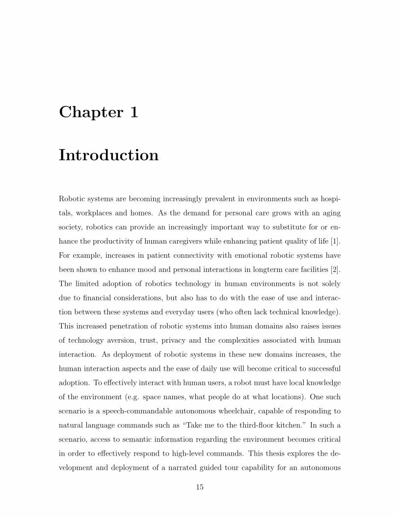
Chapter 1
Introduction
Robotic systems are becoming increasingly prevalent in environments such as hospi-
tals, workplaces and homes. As the demand for personal care grows with an aging
society, robotics can provide an increasingly important way to substitute for or en-
hance the productivity of human caregivers while enhancing patient quality of life [1].
For example, increases in patient connectivity with emotional robotic systems have
been shown to enhance mood and personal interactions in longterm care facilities [2].
The limited adoption of robotics technology in human environments is not solely
due to financial considerations, but also has to do with the ease of use and interac-
tion between these systems and everyday users (who often lack technical knowledge).
This increased penetration of robotic systems into human domains also raises issues
of technology aversion, trust, privacy and the complexities associated with human
interaction. As deployment of robotic systems in these new domains increases, the
human interaction aspects and the ease of daily use will become critical to successful
adoption. To effectively interact with human users, a robot must have local knowledge
of the environment (e.g. space names, what people do at what locations). One such
scenario is a speech-commandable autonomous wheelchair, capable of responding to
natural language commands such as “Take me to the third-floor kitchen.” In such a
scenario, access to semantic information regarding the environment becomes critical
in order to effectively respond to high-level commands. This thesis explores the de-
velopment and deployment of a narrated guided tour capability for an autonomous
15

Figure 1-1: Autonomous wheelchair in Tour-Following mode
wheelchair, aimed at acquiring semantic knowledge about the environment. The robot
acquires local knowledge when the tour guide performs a narrated guided tour while
describing the important spaces. The wheelchair constructs both metrical and topo-
logical representations of the environment, as well as an association between semantic
and spatial information acquired during the tour.
1.1 Problem Description
The research task undertaken in this project aims to address some of the technological
barriers associated with operating robotic systems in human-occupied environments,
specifically with regard to efficient deployment by non-technical users in to new en-
vironments. The end result of this research is a narrated guided tour following
capability for a speech-commandable robotic wheelchair platform, which facilitates
easy deployment. We accomplish this by having a (non-technical) person such as
16
a caregiver (who is familiar with the environment) give the wheelchair a narrated
guided tour through the environment.
Our solution addresses the need for robotic systems to interact effectively with
humans in environments where spaces are referred to by names instead of coordinates.
We demonstrate progress towards merging the gap between a robotic representation
of the environment (used for the purpose of localization and navigation) and that
employed by human inhabitants (involving functional spaces and space names). The
end result is to make the new wheelchair ready to perform high-level speech-based
navigation around the environment after the end of the tour phase.
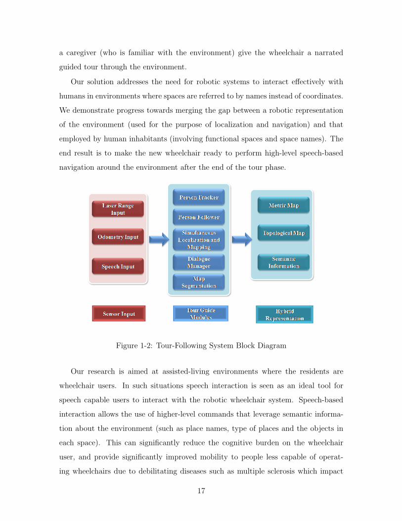
Figure 1-2: Tour-Following System Block Diagram
Our research is aimed at assisted-living environments where the residents are
wheelchair users. In such situations speech interaction is seen as an ideal tool for
speech capable users to interact with the robotic wheelchair system. Speech-based
interaction allows the use of higher-level commands that leverage semantic informa-
tion about the environment (such as place names, type of places and the objects in
each space). This can significantly reduce the cognitive burden on the wheelchair
user, and provide significantly improved mobility to people less capable of operat-
ing wheelchairs due to debilitating diseases such as multiple sclerosis which impact
17

muscular functions and motor control.
The successful implementation of such a system requires a common language with
minimal adoption requirements by users interacting with the robot, thereby promot-
ing easier integration and acceptance of the system. It should also include the names
used by people to refer to places. However, for a robot to comprehend this language,
there has to be a mapping between the semantic information about the environment
and the metrical maps used by the underlying navigation and localization algorithms.
One elegant way to achieve this is to integrate a spoken language interface to the map
building phase and acquire map information through speech based interaction.
1.2 Motivation
This research investigates the development of a scalable intuitive system for obtaining
a high-level representation of new environments. This requirement is motivated by
the need to deploy a speech-capable autonomous wheelchair in to a home/personal
care environment. For such a system to properly respond to higher-level navigation
commands, it requires both metrical and semantic representations of the environment.
An example would be a gridmap of the environment where the value would describe
the likelihood of that grid-cell being occupied, and also an association between place
names and corresponding gridmap locations. One way to obtain this information is
to manually drive the wheelchair/robot through the environment, build a metrical
map using a SLAM algorithm, then hardcode the locations of salient places on to the
gridmap. While this will certainly enable the desired functionality, it would require
the involvement of someone with technical knowledge of the system every time it
is deployed in a new environment. Thus this solution will not be scalable for wide
real-world deployment. Therefore there is a need for a method that facilitates easy
deployment of such a system into a new environment. Our approach aims to provide
a scalable solution for this requirement.
18

1.3 Thesis Overview
Following the introduction, the rest of the thesis is structured as follows:
Chapter 2 gives the background of the current problem domain and possible av-
enues of solving the requirement. It also describes relevant research that has influ-
enced our work, and the current state of the art.
Chapter 3 covers the autonomous wheelchair platform on which our solution is
implemented.
Chapter 4 describes in-depth a typical tour guide scenario and how the different
modules are integrated to help realize this functionality.
Chapter 5 describes the modules that enable person-following and interaction
during the narrated guided tour.
Chapter 6 describes how the system acquires and represents the environment
during the tour guide phase.
Chapter 7 details the trials that were carried out using our system and their
results.
Chapter 8 summarizes our approach and results, and describes possible future
work.
19

20

Chapter 2
Background and Related Work
2.1 Background
Robotic systems operate in a variety of environments and exhibit varied capabilities
for human interaction. For the tasks of navigation and localization, these systems
typically employ metrical maps, which store information about the operating envi-
ronment in a form useful to the algorithms in use. These types of environmental
representations can be used to carry out lower-level tasks such as moving forward
through a corridor, or complex tasks which are not representative of human usage,
such as traveling to an (x, y) coordinate as represented on a metrical map. But they
are less useful for carrying out higher-level tasks requiring semantic knowledge of the
environment. An example would be navigating to a particular location based on a
colloquial name (e.g. “sun room”) or finding a particular object such as a printer.
For these types of tasks, additional knowledge is required, both for the purpose of
correctly comprehending a higher-level command from a human user of the system,
as well as for the system to correctly perform the task. An example would be the
user asking a robotic wheelchair to take him to the closest microwave oven. In terms
of human-robot interaction, this type of command would require a shared language
between the human user and the robotic wheelchair, in order to understand that the
user is asking the robot to travel to the closest object of a particular class. In order to
effectively carry out the command, the robot needs to either have an idea of a space
21

containing a microwave oven, or be able to determine a likely place to find one (e.g.
a kitchen) and know where such a place would be in the environment. This would
require higher-level knowledge of the environment that would simply not be available
in a gridmap representation.
This leads to the question of how best to obtain such environment information.
One laborious and technically involved method would be to manually encode this
information in some representation (manually mapping the locations and objects to
metrical coordinates). One automated method of obtaining a subset of this informa-
tion would be to have the system automatically explore the environment with the
capability to detect specific types of objects (through vision). This would allow the
system to learn the location of certain categories of objects as well as try to infer some
of the generic space types (e.g. TV implies a high likelihood of a living room). But
this would have several drawbacks as well. First, some of the components required
for such a system, especially on-line robust object detection, are not yet technically
feasible with a moderate amount of computing resources. In addition this would not
allow the robot to learn colloquial names of locations, which would be necessary for
effective communications between a human and robot. Finally, even if object detec-
tion was 100% accurate, this would still not provide a very good method of inferring
the type for each space in the environment.
But with recent advances in technology, especially in the domain of speech recog-
nition, alternate methods for human computer interaction are becoming feasible for
everyday use. This opens up a novel way to obtain the required semantic informa-
tion of the environment as well as the metric information required for navigation
and localization. In our “Narrated Guided Tour” concept the wheelchair carries out
a spoken dialogue with a human tour guide as s/he guides the wheelchair around
the environment. The wheelchair builds a metrical map of the environment during
the tour, and acquires semantic information about the environment through speech
interaction, thereby obtaining an association between the semantic information and
metric information.
These new human-friendly interaction methods enable easier interaction between
22

humans and robots as well as allowing for high-level interactions that are more natural
to everyday users of such systems.
2.2 Related Work
The tour interpretation system that we present combines a number of research dis-
ciplines. These include human-computer interaction (HCI) concepts, Simultaneous
Localization and Mapping (SLAM), Person Following, Spoken Dialogue Management
and Map Segmentation.
With respect to the way in which users interact with robots, several “Wizard of
Oz” studies have investigated the type of interactions between a robot and a person
describing an environment. Topp et al. [3] show how personal preference and needs
affect how a person defines a particular space. They also explore the diverse nature
of introducing locations by users. Shi and Tenbrink [4] describe various methods with
which users can describe and relate spaces in their vicinity. This work indicates that
there is a tendency for users to describe spaces that are not adjacent to, or even
visible from, the current location.
The concept of using a hybrid map representation with common grounding in
human environments has been explored in an EKF localization and mapping based
robotics platform [5]. Kruijff et al. in [5] have segmented the metrical map using door
detection (either through visual detection or through assertions by the tour giver).
Its performance has been evaluated in a limited setting and thus its performance in
large spaces, such as an entire floor of a building, is unclear. In addition, due to the
space segmentation process relying entirely on door detection, it is unclear how the
system will perform in environments with many semantic boundaries but few physical
ones (such as doors or partitions).
The use of spectral clustering based on spatial connectivity for the purpose of
segmenting metrical grid maps has been outlined in [6]. Spectral clustering results in
a map segmentation that is largely consistent with the spatial characteristics of the
environment.
23

A number of research studies have been conducted on dialogue management and
speech recognition. We make use of a domain-specific, hand-crafted dialogue manage-
ment system to handle user interactions. We use a grammar that attempts to capture
the typical utterances and the SUMMIT speech recognition system [7] to handle the
speech recognition.
Simultaneous Localization and Mapping (SLAM) is another fundamental basis
for our system. There are a multitude of solutions for the SLAM problem [8],
including EKF [9], FastSLAM [10], [11] and incremental smoothing and mapping
(iSAM) [12], [13]. We make use of the latter in our implementation.
Person detection techniques have been explored using a range of sensors, includ-
ing vision [14] and laser [15], as well as a number of techniques, such as Extended
Kalman Filters and Particle Filters [15]. Kirby et al. [15] explore two methods of
following a person, one in which the robot follows the path the person took and the
other where the robot attempts to use the best path to get to the person’s current
position. Subjective evaluations carried out by participants in their study indicated
that following the person’s current position was the preferred method. Our imple-
mentation is closely related to pure pursuit [16], which has also been used by [15].
The wheelchair follows the most up-to-date estimate of the person’s location, but
only considers the goal up to a look-ahead distance.
24

Chapter 3
Speech-Commandable Autonomous
Wheelchair
Our narrated tour guide is implemented on a speech-commandable autonomous wheel-
chair research platform. It can perform high-level spoken commands such as “Go to
the living room” or “Take me to the television”.
Our goal is to deploy this system in an assisted-living or home environment where
the user will be able to delegate the navigation tasks to the wheelchair by uttering
high-level commands. This would be beneficial in situations where the user suffers
from a debilitating illness such as MS (Multiple Sclerosis), ALS (Amyotrophic Lateral
Sclerosis) or SCI (spinal cord injury) which impacts motor functions in both lower and
upper body, making the task of driving a powered wheelchair difficult and sometimes
impossible. In addition, the user will be free to focus more of his/her attention on
more productive and worthwhile activities, thereby improving quality of life.
The following sections outline some of the basic capabilities of the wheelchair.
3.1 Wheelchair Platform
The wheelchair platform is based on a Jazzy 1103 power wheelchair. It has been aug-
mented with the capabilities to sense and interact with the surrounding environment.
The wheelchair also powers the on-board laptop which runs the necessary algorithms
25

Figure 3-1: Autonomous Wheelchair Platform
that provide the autonomous capability.
3.2 Sensors
3.2.1 Laser Range Scanners
Two Hokuyo UTM-30LX laser range scanners are mounted on the wheelchair base
to give a combined 360◦ view around the wheelchair with minimal blind-spots. The
Hokuyo UTM-30LX [17] has a 270◦ field of view with a 0.25◦ angular resolution and
a range of 30.0m and provides scans at 40 Hz via USB.
The front laser is mounted under the footrest of the wheelchair, where it has an
unobscured front field of view. The rear laser is mounted higher up, underneath
the wheelchair seat. The combination of the two sensors provides a full 360◦ of the
immediate surroundings of the wheelchair.
26

Figure 3-2: Combined Laser Scanner View: Red points show front laser returns whilethe green shows rear laser returns
3.2.2 Wheel encoders
Both motorized wheels have been fitted with encoders, which provide a measure of
the revolutions made by both wheels. The encoder outputs are connected to an
Orcboard [18] which counts and transmits the number of revolutions made by each
wheel to the computer.
3.2.3 Bluetooth Microphone
Spoken input is captured through the use of a noise cancelling Bluetooth microphone
headset worn by the tour guide. This is paired to the on-board laptop.
3.3 Autonomous Actuators
Autonomous actuation is provided by an Orcboard [18] which is interposed between
the wheelchair’s joystick (otherwise used for manual control) and the wheelchair motor
controller board. The Orcboard simulates the control commands normally issued from
the joystick, based on the desired translational and rotational velocities calculated by
the navigation module. The system gives priority to manual inputs, allowing the user
27

Figure 3-3: Autonomous Wheelchair System Block Diagram
to override the autonomous operation.
3.4 Intelligence
3.4.1 On-board Computer
An IBM Thinkpad running Ubuntu and the CARMEN Robot Navigation Toolkit [19]
provides the heart of the functionality, including localization and navigation. There
is an LCD screen mounted on the wheelchair to provide with feedback as well as for
interaction with the computer.
3.4.2 Lightweight Communications and Marshalling
The underlying message publishing/handling infrastructure on the wheelchair is han-
dled by the Lightweight Communications and Marshalling (LCM) package [20]. All
28

modules ranging from navigation to localization make use of LCM to publish and
subscribe to messages.
3.4.3 Modified CARMEN Robotics Platform
The Wheelchair runs a modified version of the CARMEN Robotics platform [19], with
message publishing/handling via LCM [20]. The standard modules such as navigation
and localization have been converted to use LCM messaging.
Sensor Modules
The sensor modules publish laser and encoder information periodically, which are
used by both navigation and localization modules.
Localization
Localization is done using the Monte Carlo Localization (MCL) algorithm [21]. This
makes use of particle filters to maintain the global location of the wheelchair using
laser scans as observations (used to calculate the weights for the purpose of resam-
pling) and odometry information acquired by the wheel encoders to model wheelchair
motion.
Navigation
The navigation module converts the occupancy map to a cost-map based on the
distance to the goal. Using dynamic programing the minimum cost path is extracted
and converted to a set of waypoints which are then followed. The path is updated
continuously based on the latest localized position and regenerated periodically. The
occupancy map is updated with obstacles based on the latest laser scans.
29

3.5 Dialog Management
The wheelchair also runs an on-board dialogue manager that interacts with the user
and responds to spoken commands.
3.5.1 Speech Recognizer
We have an On-board speech recognizer (Summit Speech recognizer by the MIT
CSAIL Spoken Language Systems group [7]) as well as a Speech Activity Detector
(SAD) [22] which is continuously running on the wheelchair when it is in operation.
Thus the wheelchair is continuously listening to the user and responds immediately
without any need for a “push-to-talk” button. When the chair is in navigation mode it
uses keyword spotting to ensure that the system responds only to relevant utterances.
3.5.2 Speech Synthesizer
We use the Festival Speech Synthesis system [23] in order to provide feedback to the
user through speech, and to carry out a dialogue with the user in both tour-following
and autonomous navigation modes.
3.5.3 Navigation Mode
The normal everyday mode of operation for the wheelchair is “Navigation Mode”. In
this mode the wheelchair responds to the high-level navigation commands described
earlier. For the moment we assume that the wheelchair possess a gridmap, topo-
logical map as well as semantic information in the form of location names and their
corresponding metrical locations. The wheelchair responds to commands preceded by
a keyword e.g. “Wheelchair, take me to the activities room.” Keyword spotting helps
us drastically cut down instances of the system responding to unrelated utterances
made by the user. In addition there is a confirmation step in which the system repeats
the location name.
30

3.5.4 Speech Recognition Grammar
The following grammar is used to seed the speech recognizer in the navigation mode.
This allows us to handle the typical utterances that people use to command a location.
The grammar limits us to a particular set of utterances but this is not a hindrance
considering that we have a limited task domain in the navigation mode.
<go to> = [Wheelchair] (take me to | go to | drive to) [a | an | the] <place>
<place> = kitchen | restroom | office | lounge | cubicle | elevator | ....
31

32

Chapter 4
Narrated Guided Tour Following
This thesis focuses on a system capable of acquiring both low-level metrical and topo-
logical representations as well as semantic knowledge (such as room/object names)
of the target environment. To successfully implement this capability, we have intro-
duced the concept of a “narrated guided tour” given by a person familiar with the
environment (e.g. a care giver) to a robotic wheelchair, when it is deployed in a new
environment.
Since the aim of our research is to make the human interaction with the robotic
wheelchair as natural as possible, the tour guide system is patterned on the likely
interaction between a person being introduced to a new environment.
The “narrated guided tour following” scenario involves a sequence of human-robot
interactions. When the wheelchair is deployed into a new environment, a person
familiar with the environment initializes the wheelchair into tour-following mode by
giving it a spoken command. Once in this mode the wheelchair locates the person, by
the tour guide moving in front of the chair and indicating that fact verbally. Once the
wheelchair confirms that it sees the tour guide, the guide asks the wheelchair to follow
him/her. The guide then walks around while describing salient locations and objects,
just as he would to someone new to the building. At the end of the tour-following
phase the wheelchair has captured both metrical and topological maps as well as
semantic information in the form of location/object names with their corresponding
metric/topological locations. This representation of the environment will then be
33

exploited in the navigation phase to convey the wheelchair user to any one of the
learned locations autonomously.
Figure 4-1: Technical Modules
The following modules help us to realize the tour- following functionality by al-
lowing the chair to follow the tour guide, to build a metrical map of the environment,
to localize the wheelchair in this map (SLAM), to handle spoken interactions (both
for person following and location tagging), to augment the metric map into a topo-
logical one, and to associate space names and other semantic information to these
representations.
• Tour-Following Modules:
These modules allow the wheelchair to follow the tour guide through the envi-
ronment.
– Person Tracker Module
34

– Person Follower Module
– Dialogue Management Module
• Environment Acquisition Modules:
These modules allow the wheelchair to acquire metric and topological represen-
tations of the environment as well as associate the semantic information given
by the tour guide during the tour.
– Simultaneous Localization and Mapping (SLAM) Module
– Map Segmentation Module
Section 4.1 outlines a typical “tour guide” interaction that occurs when the wheel-
chair is deployed in a new environment. Chapters 5 and 6 outline the functionality
of the various technical modules introduced above and how they relate to the overall
functionality.
4.1 Interaction Scenario
A typical tour guide interaction with our system would play out as follows.
• When the wheelchair is deployed in an unknown environment, a person (tour
guide) who is familiar with the environment will start the system and wear the
Bluetooth capable headset. He will then verbally command the wheelchair to
go into tour-following mode.
• Once in tour-following mode the wheelchair will request the guide to stand in
front of the wheelchair so that it can initialize the guide’s location.
• Once the guide has done so (and verbally confirmed that s/he is in front of the
wheelchair), the wheelchair will search in a confined space immediately in front
of the wheelchair in an attempt to locate the tour-giver. Once the system has
a lock on the person it will issue a verbal confirmation.
35

• After the tour guide has confirmation, he can ask the wheelchair to follow him,
putting the chair into person-following mode. When the person starts moving,
the chair will follow him while attempting to maintain a 2-meter standoff. Closer
than this, the wheelchair will only rotate in place in order to keep the tour guide
in the field of view. If the person comes closer than 1m, the chair will stop all
motion until the person moves away from the chair.
• If at any time the tour guide moves farther than 5m away from the wheelchair,
it will ask the person to slow down (because the farther away the person is, the
more likely the chair is to lose tracking).
• If at any time the system loses track of the person it will stop and issue a verbal
notice of that fact. This will mean that the tour giver will have to move closer to
the wheelchair and ensure that the wheelchair is able to re-acquire the person.
• Since the wheelchair is wider than the tour guide, it is conceivable that there
will be areas that it can not travel even if the guide can go through. In such a
situation, when there is no viable path to the tour guide’s location it will issue a
verbal notice of this fact. In addition, if the wheelchair gets into a configuration
that might cause a collision, it will stop immediately and wait for the tour giver
to take corrective action. This feature ensures the safety of other people and
objects in the environment as well as the safety of the system.
• While on a tour, the tour giver will also describe the spaces in the immediate
vicinity, in the form of phrases like “We are now in the kitchen” or “I am near
a drinking fountain”. When such an utterance is made, the wheelchair will
confirm with the tour giver about which name was mentioned. If the tour-
guide confirms the recognized location, the space is tagged with the uttered
label. Otherwise there will be a clarifying dialogue to disambiguate the location
name. At the end of the tour, the tagged space names will be associated with
the relevant segmented spaces while the tagged objects will be associated with
the space in which it is located.
36
• At the end of the tour, the map will be finalized and subsequently segmented
into spaces (taking tagged locations into account). After this process the system
will be set to navigation mode for normal use.
4.2 Wheelchair and Tour guide Configurations
In the tour following phase, there can be several different configurations in which a
location tagging event might occur. These configurations are the relative position of
the wheelchair, the tour guide and the space being described. Our system handles
only the first two interactions described below. The third interaction could be handled
robustly only if the system has an estimate of the person’s orientation, but due to the
nature of the laser observations and our person tracking method, we can maintain
only a positional estimate.
4.2.1 Tour guide labels the wheelchair’s current space
In this scenario the tour guide states the name of the space currently occupied by the
wheelchair. This requires the system to have a well-segmented map, and the robot’s
current location relative to it (i.e. the space that the wheelchair was in when the label
was uttered).
4.2.2 Tour guide describes his/her current space
In this scenario the tour guide describes the current space that s/he currently occupies.
This would require the system to have the location of the tour guide at the time the
location is being tagged.
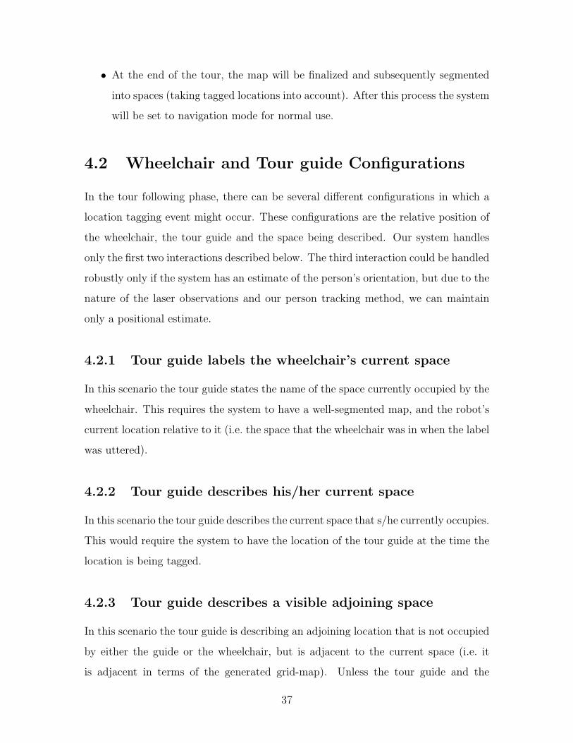
4.2.3 Tour guide describes a visible adjoining space
In this scenario the tour guide is describing an adjoining location that is not occupied
by either the guide or the wheelchair, but is adjacent to the current space (i.e. it
is adjacent in terms of the generated grid-map). Unless the tour guide and the
37
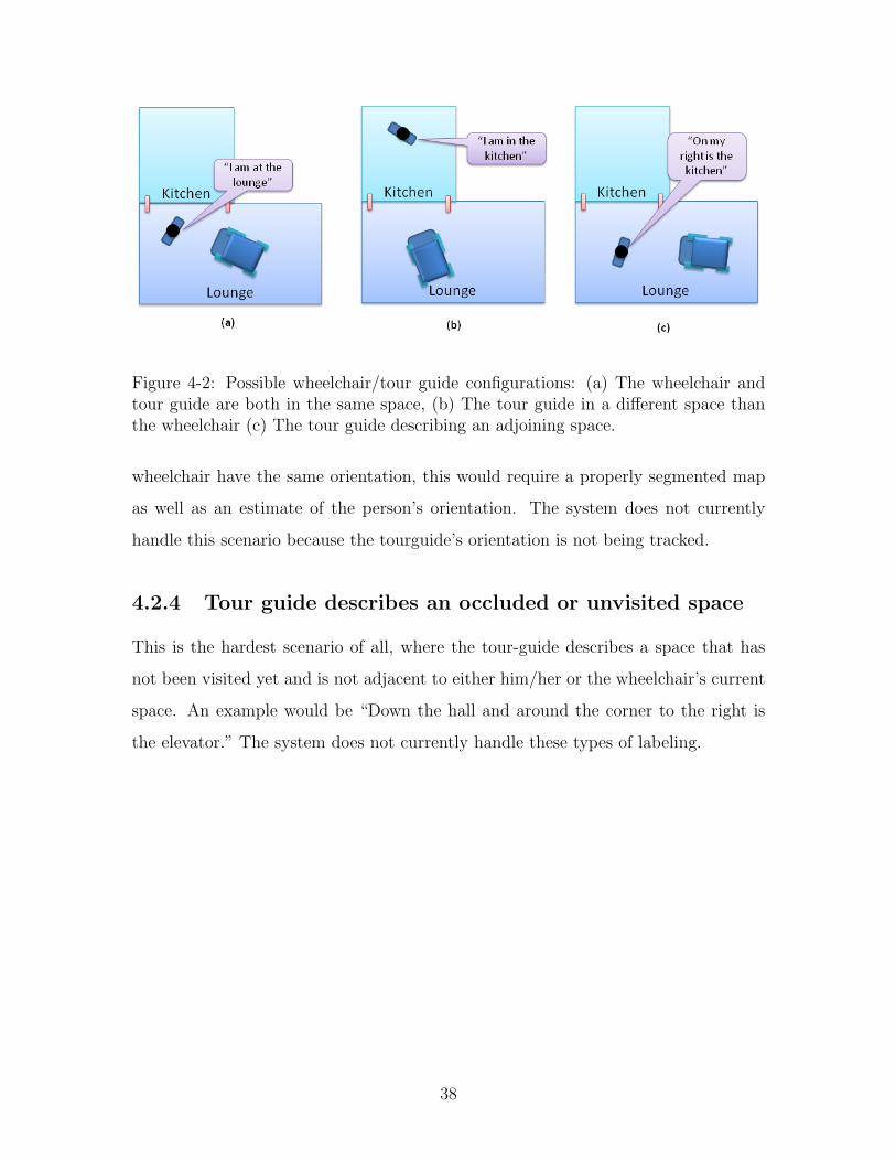
Figure 4-2: Possible wheelchair/tour guide configurations: (a) The wheelchair andtour guide are both in the same space, (b) The tour guide in a different space thanthe wheelchair (c) The tour guide describing an adjoining space.
wheelchair have the same orientation, this would require a properly segmented map
as well as an estimate of the person’s orientation. The system does not currently
handle this scenario because the tourguide’s orientation is not being tracked.
4.2.4 Tour guide describes an occluded or unvisited space
This is the hardest scenario of all, where the tour-guide describes a space that has
not been visited yet and is not adjacent to either him/her or the wheelchair’s current
space. An example would be “Down the hall and around the corner to the right is
the elevator.” The system does not currently handle these types of labeling.
38

Chapter 5
Tour Following
In order for someone to successfully give a narrated guided tour to the wheelchair,
the wheelchair must be capable of successfully following the tour guide through the
environment. This entails having an accurate estimate of the person’s location at
all times, and following the person while avoiding obstacles as well as keeping a safe
distance from other people and objects in the environment. In addition the system
must recognize and respond to spoken commands, both for the purpose of person-
following interactions and location-tagging interactions.
The wheelchair achieves this capability using the three modules described below.
• Person Tracking
• Person Following
• Dialogue Management
5.1 Person Tracking
The person tracking module handles the task of keeping track of the tour guide while
the tour is taking place. An accurate person location is required both to effectively
follow the person as well as to properly tag the described locations. The person
tracking is done solely using the two laser range scanners on the wheelchair. This
gives the chair the ability to track the person while s/he is at any orientation with
39

respect to the wheelchair (even when s/he moves behind the wheelchair). The person
tracking is carried out by extracting possible person (leg) observations from each laser
scan and then using particle filters to track the person’s position. The person location
is always relative to the current robot orientation. In fact, the person tracker tracks
both the tour guide and any other person that comes within a certain radius of the
wheelchair. The multi-person tracking is necessary to ensure human-friendly motion
during the tour.
5.1.1 Tracking
In order to track person locations, the module makes use of particle filters, one for
each person being tracked. Using 100 particles to track each individual, the module
uses the motion model described in subsection 5.1.4 to propagate the particles. The
observations are extracted from the laser returns as described in subsection 5.1.2.
The particles are then weighted according to the likelihood of the selected observation
having originated from each particle (described in subsections 5.1.5 and 5.1.6). The
particles are then resampled and summarized to arrive at the person estimate for each
filter.
5.1.2 Person Observations
Due to the low mounting height of the laser range scanners, the chair receives obser-
vations from one or both legs of the tour guide. It uses these laser range readings to
extract possible person leg observations.
• Each laser scan reading is converted to Cartesian co-ordinates in the robot frame
of reference. The algorithm then cycles through these points, clustering points
together if the next point is within a certain distance (0.1m) of the last one.
• Once the points have been clustered into segments, a simple heuristic is used
to assess whether each segment could have originated from a person’s leg (or a
combined observation from both legs if they were close enough together). The
40

Figure 5-1: Leg Observations: Segments which might have been generated by legsare circled in green
observation is classified as a possible leg observation if the segment is larger
than 0.05m and smaller than 0.6m. The lower limit of 0.05m ensures that
partially visible legs are not ignored. The upper limit of 0.6m ensures that
observations arising from two close-by legs that register as a single segment are
also considered.
• Observations from two legs are merged if there are two leg observations very
close to each other. The merging criteria is relatively conservative to avoid
merging an actual leg with a nearby object resulting in the filter converging to
the object.
5.1.3 Filter Initialization
Since the chair needs to track not just the tour guide but also other possible people
in the environment, the module creates new filters based on leg observations that
appear to move from frame to frame. A person is tracked using a particle filter with
a set of particles representing possible person positions (100 particles per filter). The
person estimate is the mean location of the particles, calculated at the end of each
41

cycle. The module uses the following procedure to decide if a new person needs to be
tracked.
• Match new leg observations with previous observations (transformed from the
previous robot frame to the current one) to detect ones that appear to have
moved. Only observations that are within a 3m distance from the wheelchair
are considered.
• Scan the previous laser scan points near these possible moved observations to
see if there were objects near by in the previous scan. This would indicate that
the new leg observation might have occurred due to a change in the sensor angle
with the object (causing a part of a wall, for example, to be detected as a leg),
and so they are ignored.
• Check the area around the moved observations to see if there is a person estimate
near by. This indicates that the observation might have come from that person.
The system avoids creating another filter in such a situation as this might lead
to failure in the tracking (because of observations being allocated to the wrong
filter).
• If neither of the above were true, then a new filter is created to track this
possible person. Due to the nature of the observations, there are observations
generated from static objects (e.g. railings) that sometimes appear to move,
leading to filters that are not tracking humans in the environment.
5.1.4 Person Motion Modeling
Due to the complexity of human motion (especially in making hard turns or sudden
stops) such motion is modeled by adding random motion to each particle (Brownian
model). At every laser scan the person particles are transformed into the current
co-ordinate frame using the odometry information that we receive (i.e. based on the
change in position). Then random Gaussian motion (zero mean with 0.05m standard
deviation) is added to every particle in each person filter.
42

5.1.5 Association of Observations with Estimates
Since the module must track multiple people, it searches through the possible leg ob-
servations and the current person estimates (mean particle positions), and matches
the closest person observations to each estimate if they are within a reasonable dis-
tance from it (0.4m).
5.1.6 Observation Model
A Gaussian observation model is used based on the distance to the observation from
the person particle. The leg observations are assumed to be distributed with a zero
mean Gaussian distribution with a 0.05m standard deviation.
5.1.7 Particle Weighting and Resampling
At each observation step, each particle is weighted based on the likelihood of the
associated observation being caused by the particle using the model described in
subsection 5.1.6. Particles are then re-sampled to ensure that the most likely particles
survive to the next step. This weighting and resampling are carried out only if there
was a relevant observation near the person estimate.
5.1.8 Selecting the Tour guide
Since only one of the tracked persons is the tour guide, the module requires an
initialization command from her/him indicating that s/he is in front of the wheelchair.
Then it cycle through the current person estimates to see which one is within the valid
region. If there is a person estimate that fits the criteria, that is selected as the tour
guide’s estimate and used for person following tasks.
5.1.9 Filter Management
Other than the tour guide, other people are tracked if they are near the wheelchair (i.e.
within 3.0m) in order for the person-following to be human friendly. Therefore filters
43

Figure 5-2: Person Tracking: (a) Moved legs (in yellow); (b) Multiple persons beingtracked (red circle shows the tour guide’s position and light green circles are thenon-tour guide people being tracked - one of which is a false detection).
Figure 5-3: Person Tracker Performance: (a) The current laser scan and estimatedperson position in red circle; (b) The robot in the context of the overall map built sofar and the tracked person location in global context (red circle), the best heading tofollow (light red line) and the actual person heading (yellow).
44

are created only for moving leg observations within this boundary and eliminated
once the estimate moves outside this region. Also filters are terminated if they go
over one second (40 observation cycles) without registering a valid observation. If the
terminated filter happens to be tracking the tour guide, a verbal message is issued
indicating that the guide is no longer visible.
5.1.10 Person Observation Removal
Due to the fact that the tour guide is constantly in view of the laser range scanners,
the laser returns typically contain the leg observations. Since these laser returns
are subsequently used for both person following as well as map building, the person
tracker removes the person observations from the laser returns and republishes a
modified laser stream to be used by the other modules. Due to the less stringent
method employed in creating people filters, only leg observations attributable to the
tour guide are removed. This is done by removing laser points from the two closest
leg detections near the tour guide by setting the range to maximum distance.
5.2 Person Following
While the person tracking module keeps track of the person location, a person fol-
lowing module implements the following behavior in order to follow the tour guide
through the environment. The person following module implements this behavior
using only the person location and the latest laser scans. This module aims to make
the person-following conducive to effectively conducting the tour.
The person following module takes different actions based on the guide’s proximity
to the wheelchair, to ensure the safety of the tour guide as well as to ensure successful
progress of the tour. For this purpose the area around the person is categorized into
three zones.
• Personal Space: This is the immediate space around the person, which is
considered to be within 1.0m from the person. In this range the wheelchair
45

refrains from making any motion (even rotate-in-place motion is suppressed).
• Intermediate Space: This is the area that is still relatively close to the person
while not being in his/her immediate vicinity. Locations between 1.0m and
2.0m from the tour guide are considered to be in the intermediate space. If the
wheelchair is within this range it executes only rotate-in-place motions in order
to keep facing the person’s position as closely as possible.
• Followable Space: These are all locations over 2.0m from the tour guide.
When the wheelchair is more than 2.0m from the person it executes a follow
action, where the best heading is chosen as described in subsection 5.2.1 and
the translational and rotational velocities are chosen so as to best move the
wheelchair to obtain that heading and achieve a 2m standoff.
In addition to these behaviors, the algorithm modulates velocity based on the
distance of obstacles, the difference in the robot heading, goal heading and the best
direction heading as well as the distance of other people in the vicinity.
5.2.1 Navigation Algorithm
The navigation works on the basis of the local laser scan observations. The algorithm
works as follows.
Conversion to local frame of reference
The data from both laser range scanners are converted to the robot frame of reference
taking to account the offsets created by the positions of the lasers with respect to the
robot frame.
Goal Heading and Location
The direction of the tour guide in the robot frame of reference is used, along with the
look-ahead distance (2.0m) to set the goal for the navigation algorithm.
46

Figure 5-4: Person Follower: The dark red circles show the obstacle points expandedby the radius of the robot.
Segmentation of field of view
The combined field of view of the laser range finders is 360◦. This is segmented into
buckets each 2.5◦ wide.
Best Heading Selection
• The module calculates the minimum distance for each ray (and the point of
intersection) that can be traveled along the ray direction without a collision.
• Each ray is scored based on the following formula (see Figure 5-6 (a)).
DCF = Maximum Traversable distance without collision (up to 2m) (5.1)
Dgoal = Distance between farthest free point on ray and goal (5.2)
score[ray] = DCF/[1 +D2goal] (5.3)
47

Figure 5-5: Person Following: (a) The person-follower behavior when the wheelchair iswithin the intermediate space of the tour guide; (b) The wheelchair with surroundingrays considered for the purpose of navigation in blue, the person heading in yellowand the selected best heading in light red.
• Once scores are calculated for the entire field of view, they are averaged using
a moving window of 5 segments to each side. This is done to ensure smooth
navigation and to ensure that there will be no corner cutting.
• The heading with the best averaged score is selected as the best heading to
follow to get to the goal point.
Velocity Commands
Once the best heading has been selected, the translational and rotational velocity
are calculated using the below equations. They take into account both the difference
between the best heading and the actual robot heading, and the distance to the goal.
The velocity is biased on the distance from the robot to the tour guide to ensure
smooth person following and to prevent the wheelchair from lagging too far behind
the tour giver.
The rotational velocity is arrived at using the formulas below. The angle difference
is clamped in Equation 5.6 so that the robot’s rotational velocity is at a high enough
48

value for small angle differences but is not too high when the difference in heading
becomes higher (see Figure 5-6 (b)):
DBest robot = Best Heading− Robot Heading (5.4)
RVMax = Maximum Rotational Velocity (5.5)
RV =CLAMP (−(π/4), DBest robot, (π/4))
(π/2)×RVMax (5.6)
The translational velocity is arrived at as shown below. The translational velocity
should be high only if the robot is facing towards the tour guide’s location. In
addition, the ratios defined in equations 5.9 and 5.10 ensure desirable behavior in the
wheelchair’s motion.
• Equation 5.9 ensures that the translation velocity is moderated by the distance
to obstacles in our desired heading. Otherwise the wheelchair might travel at a
higher than desired velocity, leading to a collision.
• Equation 5.10 reduces the wheelchair’s speed when it is going through narrow
gaps in order reduce the chance of a collision on the side and to reduce the
impact in such a situation.
• Equation 5.11 is higher at smaller angle differences and vice versa for higher
differences.
DGoal robot = Goal Heading− Robot Heading (5.7)
DL = Look ahead distance (2.0m) (5.8)
RBest distance = max
(Avg free distance in best heading
DL
, 1.0
)(5.9)
RClosest sidegap =Closest side gap
0.6(5.10)
RAD =Abs (DGoal robot − to radians(100◦))
to radians(100◦)(5.11)
TVMax = Maximum Translational Velocity (5.12)
49
Figure 5-6: Person Follower: (a) Different distances used; (b) Different headings andangles used for velocity calculations.
TV = RBest distance ×RClosest sidegap × TVMax (5.13)
Turn-In-Place
If DBest robot is larger than 80◦, the wheelchair turns in place until the angle is less
than 80◦. This prevents the wheelchair from doing very large arcs when it can turn in
place within a shorter time. This type of situation occurs when the tour guide goes
around a corner, or if s/he turns back and walks toward and past the wheelchair.
Safety
Safety in the context of person-following has a number of aspects.
• Collision when traveling forward: If the wheelchair comes close to collid-
ing due to some failure in the navigation algorithm or due to a change in the
environment, the wheelchair stops and issues a notice of the fact. This is done
by checking if there are any obstacle points that are within a threshold of the
robot footprint, before every control cycle. If such a detection occurs, the sys-
tem immediately halts all motion and issues a verbal notice. In practice this is
rarely triggered and acts as a last fail-safe to prevent collisions.
50

Figure 5-7: Person-Follower Obstacle avoidance and smooth cornering: The greenline shows the path taken by the wheelchair. It avoids obstacles and also refrainsfrom cutting corners.
Figure 5-8: Area that is scanned for the presence of a human is shown bordered indashed red.
51

• Collision due to turn-in-place: Another type of motion that the wheelchair
executes when following a person is the turn-in-place. When the wheelchair
requires to turn-in-place, it checks if there are any obstacles within a threshold of
its radius (this is different than the footprint, as the wheelchair is approximately
rectangular). If a possible collision exists during turn-in-place the wheelchair
does one of two things based on the situation.
– Within Intermediate space: If the wheelchair lies in person’s intermediate
space, it is likely that when the person starts to move again, s/he can be
followed without rotating in place. Thus the wheelchair halts all rotation
until the person moves to “followable space”.
– Large turn angle: If the turn-in-place requirement was brought on by a
large angle difference, the chair refrains from turning in place and moves
along the best heading (as it would if the heading was smaller). If this
resolves the collision, the system would end up turning in place at this new
clear location. Due to safety issues the chair is prevented from traveling
away from the tour guide (i.e. at bearings more than 90◦ away from the
direction to the tour guide).
• Ensuring the safety of other people in the environment: Since the
wheelchair operates in environments where humans other than the tour guide
are present, we desire a human-friendly motion to ensure the safety of these
occupants. The collision prevention procedure detailed in the above points
minimizes the chance of colliding with objects. But this is not sufficient for
dealing with humans. Firstly, humans are not static objects and if someone
makes a motion toward the robot while the robot is between control cycles,
there could be a collision. Secondly, even though the robot might clear an
obstacle with only a close gap doesn’t mean that it is acceptable behavior when
dealing with humans. Thus the multi-person tracking capability of the person
tracker is used to ensure the safety of the human occupants in the environment.
This is done by scanning the immediate area in the direction of the best heading
52

(see Figure 5-8) to see if there is any person in this area. The module uses the
person tracking estimates to accomplish this. If there is a person in this area,
the chair pauses until the person moves away from the area. This prevents sit-
uations where someone might walk between the tour guide and the wheelchair
while the wheelchair is following the tour guide (i.e. when the person is in “fol-
lowable space”). The system scans a rectangular shaped space on our heading
direction up to 1m distance from the wheelchair. A rectangular shape is used
(as opposed to an arc) in order to avoid responding to false person detections
(see subsection 5.1.3) that might occur near the walls (on its sides). If the
scanned area was larger, the wheelchair would be too conservative and would
refuse to move in certain situations even though there is no safety implication
on humans in the environment (because it thinks there is a person near the
path).
5.3 Dialogue Management
The dialogue management system is at the heart of the narrated guided tour-following
capability. This handles all interactions with the human tour guide and the wheelchair.
The dialogue manager continuously listens to the tour guide, detects occurrences when
the person speaks to the wheelchair and then interacts with the tour guide in an in-
telligent manner to carry out the desired action. In the tour-following mode the
interactions with the user are of two types.
• Person-Following interactions These are interactions with the tour guide,
at the start and during a tour. These include the tour guide asking the chair to
locate him/her, asking to start/stop following him/her, and indicating the end
of a tour. The tour guide can also ask the system to stop listening (e.g. when
s/he has to talk with someone else) and to resume listening.
• Location/Object tagging interactions These deal with the task of obtain-
ing semantic information about the environment, in the form of place names
53

and objects located in the spaces. The dialogue manager will attempt to dis-
ambiguate any utterances to make sure that the system has the correct label.
The dialog manager consists of the following components.
• Speech Activity Detection System
• Speech Recognition System
• Speech Synthesizer
• Handcrafted Logic
5.3.1 Speech Activity Detection System
In order for the narrated guided tour to be as natural as possible, the dialogue manager
continuously listens to the tour guide, and responds accordingly when a relevant
utterance is made. This requires a speech activity detection system, that detects both
the onset and conclusion of each tour guide utterance. The power of the acquired
signal at each segment in time is used to decide whether it is a speech segment or not.
The speech activity detection system [22] uses the frame-by-frame classifier combined
with smoothing logic to decide if an audio segment is speech or not, and forwards it
to the speech recognition system as needed.
5.3.2 Speech Recognition System
The wheelchair uses the SUMMIT Speech recognition system [7] in conjunction with
a relatively expressive grammar for the tour-following task. SUMMIT uses Finite
State Transducer (FST) networks to transform audio which matches a set of low-level
acoustic models into recognized utterances which obey a series of grammar rules. We
do not retrain the acoustic models, but only define the desired grammar for the task
at hand. We have only to define the grammar rules appropriate to our application.
We use the gstreamer element of SUMMIT (pocket SUMMIT), which was designed
to be used purely standalone.
54

The grammar covers both location labeling and person following utterances made
by the tour guide. The following describes the grammar used in tour-following inter-
actions.
• Person Tracking and Following related Utterances:
– Initializing person tracking: “I am in front of you”
– Query tracking state: “Do you see me”
– Start following: “Start following me | Follow me”
– Stop following: “Stop following [me] | Stop”
– End of tour-following: “[We are] done with the tour”
• Location/Object tagging Utterances:
– <place tagging> = <perspective> [now] <position loc> [a | an | the]
<place>
– <object tagging> = <perspective> [now] <position obj> <object>
– <perspective> = i am [view=guide] | we are [view=both] | you are [view=
wheelchair]
– <position loc>= (in | at | going through) [pos=at] | entering [pos=entering]
– <position obj> = (at | near) [pos=at] | facing [pos=facing] | approaching
[pos=approaching]
– <place> = kitchen | living room | office | lounge | cubicle | ....
– <object> = table | chair | printer | water fountain | microwave | ....
The critical information contained in a tagging utterance are the following.
• Perspective of the tagging: This can be that of the tour guide or the
wheelchair (see Figure 4-2, pg. 38). This is vital to the map segmentation
process, as the map partitioner uses the “place tag” locations as the basis of
calculating semantic distances.
55

• Relative location of the tour guide or the wheelchair: The relative
location of the tagging might be inside the space (e.g. “I am now in the lounge”)
as shown in Figures 4-2 (a) and (b), in front of the space (e.g. “I am facing the
elevator”) or to the side (e.g “On my right is the kitchen”) as in Figure 4-2
(c). This is also critical to properly handle the labeling. Our system deals only
with utterances that are made inside the space being described; therefore only
utterances describing the currently occupied space are allowed.
• Place/object name: This is the semantic information that we acquire from
the tagging interaction, and is vital for the navigation phase.
5.3.3 Speech Synthesizer
The wheelchair generates audible speech using the Festival speech synthesizer [23], in
order to respond to utterances made by the tour guide. The chair’s responses are in
the form of questions about confirmations, responses to commands etc.
5.3.4 Handcrafted Logic
The responses to spoken commands have been handcrafted because of the limited
task space that we are dealing with. Our implementation does not yet take into
consideration the uncertainty associated with user speech recognition or inference of
intent.
• Person Following: When the tour guide tells the system that s/he is in front
of the wheelchair, the system initializes the person tracking system. Once the
tracker “locks on” to the person, a verbal confirmation is made so that the tour
guide is free to start the tour. When the tour guide is ready to head out, s/he
utters the “follow” command. If the tracker has “locked on” to the tour guide, a
confirmation is issued that the wheelchair is following, and the person following
system is started.
56

• Tagging Locations/Objects: In a tagging utterance the chair ask for con-
firmation from the tour guide by repeating the most likely tagged utterance.
Once the system has confirmation, it associates the time of the tagging and the
tagged name which are mapped with the position of the robot/person location.
57

58

Chapter 6
Tour Interpretation
The purpose of the tour interpretation subsystem is to acquire metrical, topological
and semantic level representations of the environment traversed through during the
guided tour.
The metrical representation is in the form of a gridmap denoting the probability
of each (discretized) (x, y) location being occupied. The metric map building is done
on-line using the iSAM-SLAM algorithm [12]. The semantic information is associated
with the metric representation during the tour. At the end of the tour the system
has captured a metrical map, the robot positions at each LIDAR sample instant
during the tour, and the time-stamped semantic information. When time-stamps
are matched with robot locations, the system obtains the metrical locations for each
semantic tagging. Then the metrical map along with the tagged locations are used
by the map partitioning module to obtain a spatially and semantically consistent
topological map, where each node corresponds to a space (e.g. room). Once the
topological map has been extracted, the system matches the semantic information,
in the form of location names, to relevant spaces and includes any objects described
during the visit to the corresponding space. At the conclusion of this process, the
wheelchair will have acquired all desired information about the environment.
59

Figure 6-1: SLAM Output: Segments which might have been generated by legs arecircled in green.
6.1 On-line Simultaneous Localization and Map-
ping
The on-line SLAM module performs Simultaneous Localization and Mapping (SLAM),
and periodically publishes the robot pose and updated grid maps. The module allows
the robot to construct a map of the environment while also localizing itself within
this map simultaneously.
A modified version of the iSAM-SLAM module [12] of the CARMEN3D package
is used for this purpose. This utilizes incremental smoothing and mapping (iSAM)
to carryout real-time SLAM.
6.1.1 Removal of Person Observations
When the chair builds the map, it will have the tour guide lead it through the en-
vironment. Therefore, if the laser returns are used without any modification, the
person’s legs will be registered as obstacles in the environment. Thus the constructed
map would not be very useful due to the non-existent obstacles along the path of
the human. To avoid this, the SLAM module uses a modified stream of laser mes-
sages, published by the person tracking module (see 5.1.10), that suppresses the laser
returns caused due to the tour guide’s legs.
60

6.1.2 Map Construction and Location Association
The map construction and location association module represents the environment
using a set of nodes and the laser returns attached to these nodes. During the
smoothing and loop closing processes these nodes will be the ones that get updated.
Therefore new nodes are created whenever an utterance is detected, and the tagging
information is attached if and when the dialogue manager confirms the nature of the
utterance. Thus the tagged nodes will always be consistent with the gridmap built
by the module. In addition the relative position of the tour guide at each node is
also maintained for use in associating the tagged locations. The module periodically
converts the node list and the attached laser returns into a metric gridmap and
publishes this for use by other modules.
6.1.3 Tour Conclusion
Once the tour guide indicates that the tour has ended, the SLAM module publishes
the final version of the gridmap. This is used by the map partition module to create
a topological map. In addition, this map is used by the localization and navigation
module in the normal mode of operation.
The SLAM module also publishes the tagged locations. The tagged locations con-
tain all the semantic information gathered during the tour, and the metrical location
where each utterance was made. If the nodes were tagged from the perspective of the
tour guide, the tagged location is associated with the tour guide location at the time
of the tagging, otherwise the wheelchair location is used.
6.2 Map Segmentation
Once the SLAM module publishes the final metric map and the associated semantic
information in the form of a tagged place list, the map segmentation module uses this
information to segment the metric map and convert it to a topological map.
The map segmentation module uses the spectral clustering method outlined in [6]
61

Figure 6-2: Map Segmentation: Shows the result of the segmentation process on theBoston Home second floor (spaces names are shown inside red boxes and object namesare shown inside green boxes).
to segment the map into spatially consistent segments, while also incorporating the
semantic information to infer logical boundaries. An example situation of a logical
boundary would be two different “places” contained within the same physical space.
6.2.1 Multiple Tagged Locations
There might be situations where the guide labels the same place multiple times at
different locations within the same space. In such a situations, all the tagged locations
(describing the same space) must be considered together. This is done by allowing
each place to have more than one associated metrical location. When the visibility
and weights for the semantic distance are calculated, the closest tagged point for each
place is used.
62

Figure 6-3: Creation of the distance matrix (connected points are linked using greenlines while landmark visibility is shown using blue arrows): (a) Points 1 and 2 areconnected as they have a clear line of sight while point 1 and 3 are not (because theyare not mutually visible); (b) Points 1 and 2 are connected as they see the same landmark and each other while point 1 and 3 are not connected as they don’t see eachother even though they see the same landmark.
6.2.2 Segmentation Process
Map segmentation, based on the method used by Tom Kollar in [6], is carried out as
below.
• First the metrical map is reduced to a skeletal representation of the free space
points in the map. Clustering is carried out on these points, as opposed to
the entire map, in order for the process to be tractable. These points are used
to create a graph in which two points are connected if and only if they are
co-visible.
• The algorithm creates a distance matrix between these points that is used to
cluster the points using spectral clustering. The points are weighted by both
their Euclidean distance and semantic distance from one another. The semantic
distance is calculated based on the visibility of landmarks (labeled locations)
from each point.
• The overall distance is a combination of the semantic distance between the
63
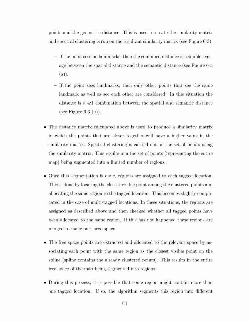
points and the geometric distance. This is used to create the similarity matrix
and spectral clustering is run on the resultant similarity matrix (see Figure 6-3).
– If the point sees no landmarks, then the combined distance is a simple aver-
age between the spatial distance and the semantic distance (see Figure 6-3
(a)).
– If the point sees landmarks, then only other points that see the same
landmark as well as see each other are considered. In this situation the
distance is a 4:1 combination between the spatial and semantic distance
(see Figure 6-3 (b)).
• The distance matrix calculated above is used to produce a similarity matrix
in which the points that are closer together will have a higher value in the
similarity matrix. Spectral clustering is carried out on the set of points using
the similarity matrix. This results in a the set of points (representing the entire
map) being segmented into a limited number of regions.
• Once this segmentation is done, regions are assigned to each tagged location.
This is done by locating the closest visible point among the clustered points and
allocating the same region to the tagged location. This becomes slightly compli-
cated in the case of multi-tagged locations. In these situations, the regions are
assigned as described above and then checked whether all tagged points have
been allocated to the same region. If this has not happened these regions are
merged to make one large space.
• The free space points are extracted and allocated to the relevant space by as-
sociating each point with the same region as the closest visible point on the
spline (spline contains the already clustered points). This results in the entire
free space of the map being segmented into regions.
• During this process, it is possible that some region might contain more than
one tagged location. If so, the algorithm segments this region into different
64

Figure 6-4: Map Segmentation: (a) The extracted skeleton for a gridmap of the firstfloor of the Boston Home; (b) The points of the skeleton after spectral clustering (dif-ferent colors denote different regions); (c) After the full clustering process (includingsegmentation of spaces assigned multiple clusters).
regions based on the closeness of each point to the relevant tagged location.
This ensures logical consistency of the segmented spaces.
The resulting map segmentation takes into account the spatial characteristics due
to the geometric shape of the environment (introduced based on the visibility of points
to each other and the geometric distance) and also the semantic characteristics that
are introduced based on the visibility of the landmarks. Thus this will result in
the map being divided into spaces based on spatial features, and also being further
divided based on whether there is more than one landmark in any space.
6.3 Association of Semantic Information
As outlined in 6.2.2, the map partitioner ensures that each semantic location is asso-
ciated with a single space, and that no two semantic locations are assigned the same
space. Thus at the end of the partitioning process the wheelchair possess the corre-
spondence between spaces and the semantic information. Each object is attached to
the space in which the tagging of that object occurred.
65

66

Chapter 7
Results
The tour following and interpretation system was tested in a number of environments
with both technical and non-technical people giving tours around the environments.
A total of 6 tours were conducted by 4 users, on several floors in the Stata center at
MIT (floors 2, 3 and 8) and at The Boston Home (TBH) [24] resident care facility
(all three floors). In The Boston Home, two of tours were conducted by facility
administrators who were given only a brief introduction as to how to conduct a tour.
Table 7 outlines the quantitative parameters of the 6 narrated guided tours conducted.
Table 7.1: Tour Following Results
Location Floor Duration Distance # places # objects(mins) travelled (m) described described
Stata 2 10 202 6 12Stata 3 13 234 5 5Stata 8 15 173 4 11TBH 0 15 243 4 7TBH 1 27 392 19 7TBH 2 19 340 17 8
In each tour, the tour guide wore the Bluetooth headset, initialized the person
tracking and person following, and guided the wheelchair through the respective
floors. The guides described both places that they currently inhabited, and objects
near their locations. They were instructed about the typical grammar that is rec-
67

ognized by the system. All modules other than the map partitioner were running
on-line. This included the SLAM module, which built metrical maps in real time as
tours were being conducted. The map partitioning was carried out after all the tours
were concluded (in the interest of time), although it is certainly possible to have the
partitioning happen at the conclusion of each tour.
7.1 Person-Following Results
Some of the resultant paths followed by the wheelchair during some of the narrated
guides tours are shown in Figures 7-1 and 7-2.
In all these trials, the wheelchair was able to follow the person in a safe manner
around all accessible locations around the environment (some locations were not ac-
cessible because of narrow entryways). The wheelchair did not stray unnecessarily
close to the tour guide, and did not stray too close to the walls and other objects unless
the gap was small. In addition it was able to handle several instances in which other
wheelchairs were moving in its vicinity, although the tour guides were instructed to
minimize such occurrences due to safety concerns. There were some instances where
the wheelchair lost track of the tour guide, either because the guide went around a
corner (and was not visible to the wheelchair) or because s/he strayed too close to
some object in the environment that produced observations similar to a leg. In all
instances the tour guide was successfully able to resume the tour, by going through
the initialization step described in subsection 5.1.8.
7.2 Map Construction and Segmentation Results
The resultant metrical maps, the segmentations and the architectural floor plans
containing the logical boundaries are shown in Figures 7-3, 7-4, 7-5 and 7-6.
68

Figure 7-1: Person-Following performance: TBH First floor
Figure 7-2: Person-Following performance: TBH Second floor
69

7.2.1 Location Tagging
Most general locations were tagged without any complications, although due to the
limited nature of the vocabulary used during the trials, some location/object tags were
not recognized. For example in one instance the guide attempted to label “Marva’s
office” but since this was not in the vocabulary, it was only recognized as “office”.
During the trials 100 out of 105 place/object tags were registered from the tour
guide’s perspective, with the guide either occupying or facing the location. Since
the tour guides did not venture inside some locations such as elevators/restrooms
(nor were they visible), they have been treated as objects (since there would not be
a corresponding space in the metric map). Therefore, they have not influenced the
segmentation process.
7.2.2 SLAM Performance
The SLAM module constructed consistent maps of all the explored floors. Some
paths included several loops; the SLAM module performed all required loop closures,
and map construction occurred in real-time while the tour was being conducted. In
addition, as can be seen from the overlay images in Figures 7-3, 7-4, 7-5 and 7-6, the
metric maps are consistent with the architectural floor plans for these floors.
7.2.3 Segmentation Performance
Figures 7-3, 7-4, 7-5 and 7-6 show the resulting segmentations compared with the
architectural drawings available for these locations.
Segmentation Accuracy
Rooms with distinctive spatial structure (see figure 7-7) are segmented almost ideally
by the partitioning process. In situations where there is little spatial segmentation
(e.g. charging stations along the sides of long hallways) the partitioned spaces tend to
be larger than logical spatial boundaries. Since spatial structure along corridors tend
to indicate a continuous space, when semantic information is added, the partitioning
70

Figure 7-3: Map Segmentation: The Boston Home Ground Floor: (a) The segmentedmap generated by the tour guide; (b) The architectural floor plan of the same spaceincluding logical boundaries (yellow denotes the walls); (c) Metrical map overlaidwith the floorplan.
Figure 7-4: Map Segmentation: The Boston Home First Floor: (a) The segmentedmap generated by the tour guide; (b) The architectural floor plan of the same spaceincluding logical boundaries (yellow denotes the walls); (c) Metrical map overlaidwith the floor plan.
71

Figure 7-5: Map Segmentation: The Boston Home Second Floor: (a) The segmentedmap generated by the tour guide; (b) The architectural floor plan of the same spaceincluding logical boundaries (yellow denotes the walls); (c) Metrical map overlaidwith the floor plan.
Figure 7-6: Map Segmentation: Stata Center Third Floor: (a) The segmented mapgenerated by the tour guide; (b) The architectural floor plan of the same space in-cluding logical boundaries (yellow denotes the walls); (c) Metrical map overlaid withthe floor plan.
72

Figure 7-7: Map Segmentation: Spatially consistent segmentations: (a) A properlysegmented space representing the living room; (b) A properly segmented space forthe dining room.
Figure 7-8: Map Segmentation: Logical segmentations: Shows a space that wasassigned two semantic locations (TV room and the nurses’ station - this has beenpost-processed and segmented based on the distance to each tagged location. Theboundary is shown in yellow).
73

Figure 7-9: Map Segmentation: Multi tagged locations (red circles show the taglocations while the orange lines show the segment boundaries): (a) Shows the chargingstation tagged twice and segmented properly; (b) Show the nurses’ station taggedthree times and segmented in to a single space; (c) Shows the cyber cafe where onlytwo of the tags were recognized to be from the same location, which led to the samespace being split in two.
sometimes results in arbitrary boundaries. In situations where a space may contain
more than one semantic location, this is handled by the post-spectral clustering step
described in subsection 6.2.2 (see Figure 7-8). This sometimes, however, leads to
not-so-natural-looking space boundaries.
Association of Multi-tagged locations
There were a number of locations which were tagged multiple times during the tour.
On the whole the method that was employed to decide and combine these tags to a
single semantic location proved to be adequate (see Figures 7-9 (a) and (b)). In some
instances, however, this did not result in a correct association of some tags, which
led to the partitioner to treat this location as a separate logical space (see Figure 7-9
(c)).
The overall performance of the map partitioning process is satisfactory even
though some segmentations do not necessarily agree with logical space boundaries.
Given limited spatial characteristics in defining logical boundaries, inconsistency with
the actual logical boundaries seems unavoidable using the current method.
74

Chapter 8
Conclusion
The overall goal of this research is an end-to-end solution to facilitate efficient and easy
deployment of a robotic wheelchair system into a new environment. Our wheelchair
is a speech-capable system with the capacity to interpret and implement simple high-
level navigation commands. The end-to-end solution encompasses a narrated guided
tour capability. The wheelchair is given a narrated guided tour by a human tour guide
around the environment, and “learns” both a metrical map of the environment as well
as a topological map along with associated semantic information. It then makes use
of this gathered information, combined with speech-based user interaction, to offer a
broader range of functionality to the user. We believe that such methods will improve
the acceptance of complex robotics systems in everyday human environments, and
improve the quality of life of people in assisted living environments.
8.1 Future Work
We plan to carry out a formal user study of the performance of the narrated guided
tour capability. Since the goal of the system is to allow even a non-technical person to
introduce our system into any new environment, our target user group would include
non-technical persons.
In addition there are a number of extensions that would enhance both the tour
following and interpretation aspects.
75

In terms of giving the narrated guided tour, one useful aspect would be the in-
clusion of a mechanism for handling closed doors. This situation arises when some
of the spaces in the environment are behind doors that are normally closed, requir-
ing the tour guide to hold the door open while the wheelchair proceeds. In such a
situation, pure person following would not be a sufficient mechanism for getting the
wheelchair through the door. We envision a capability in which the tour guide leads
the wheelchair up to the door, opens the door, then commands the wheelchair to
go through the door. Upon this command, the wheelchair scans the area in front,
detects the opening most resembling an open door, picks the best path through the
door, passes through the door and travels for a certain distance, and finally waits for
the guide to overtake it and resume the tour.
In terms of understanding location utterances, the system is currently limited to
understanding utterances describing the current location. We want our system to
handle not just location tagging in spaces that are currently occupied by the guide,
but also situations in which adjacent (visible) locations are described. One way to do
this is by keeping track of the tour guide’s orientation as well as position. This is not
done currently, as we do not model the person’s orientation and velocity. We plan to
evaluate both the possibility of improving person tracking with the infusion of these
parameters, as well as the accuracy of the tracked orientation. We would also like to
implement the ability to handle more advanced descriptions that describe or refer to
spaces that have not yet been explored during the tour.
We also plan to allow for more free-form types of utterances when describing the
environment during the narrated guided tour. This would entail moving away from
the context-free grammar-based speech recognition model that we are currently using,
toward an n-gram model. We also wish to gather a corpus of typical utterances that
people use when they describe surrounding locations, that could be used to train the
n-gram model. This would also require a natural language processing component to
understand recognized utterances.
Finally, we are also interested in implementing this capability on other robotic
platforms. One of the advantages of the tour-following capability is that it can allow
76

for easy deployment of systems that would not be as easily “driven” around an envi-
ronment as a wheelchair. We are in the process of implementing the tour following
capability onto a small robotic rover platform built as a companion to an autonomous
forklift. The rover is tasked with exploring the environment and learning salient in-
formation (in this context this would be delivery zones, pallet storage areas etc.).
Currently the tour-following component has been implemented and tested and shows
adequate performance on the rover.
77

78

Bibliography
[1] J. Forlizzi, C. DiSalvo, and F. Gemperle, “Assistive Robotics and an Ecologyof Elders Living Independently in Their Homes,” Human-Computer Interaction,vol. 19, no. 1, pp. 25–59, 2004.
[2] K. Wada, T. Shibata, T. Saito, and K. Tanie, “Analysis of factors that bringmental effects to elderly people in robot assisted activity,” in IEEE/RSJ Inter-national Conference on Intelligent Robots and System, vol. 2, pp. 1152–1157,2002.
[3] E. A. Topp, H. Huttenrauch, H. I. Christensen, and K. Severinson Eklundh,“Acquiring a shared environment representation,” in Human-Robot Interaction(HRI06), Salt Lake City, UT, pp. 361–362, 2006.
[4] H. Shi and T. Tenbrink, “Telling Rolland where to go: HRI dialogues on routenavigation,” in Workshop on Spatial Language and Dialogue, Delmenhorst, Ger-many, 2005, 2005.
[5] G.-J. Kruijff, H. Zender, P. Jensfelt, and H. Christensen, “Situated dialogue andunderstanding spatial organization: Knowing what is where and what you cando there,” in The 15th IEEE International Symposium on Robot and HumanInteractive Communication, 2006., pp. 328–333, 2006.
[6] T. Kollar, E. Brunskill, and N. Roy, “Topological Mapping Using Spectral Clus-tering and Classification,” in IEEE/RSJ International Conference on IntelligentRobots and Systems, 2007. IROS 2007., pp. 3491–3496, 2007.
[7] I. Hetherington, “PocketSUMMIT: Small-Footprint Continuous Speech Recog-nition,” in Interspeech, Antwerp, Belgium, 2007.
[8] H. Durrant-whyte and T. Bailey, “Simultaneous Localisation and Mapping(SLAM): Part I The Essential Algorithms. Robotics and Automation Magazine,”IEEE Robotics and Automation Magazine, vol. 2, p. 2006, 2006.
[9] R. Smith and P. Cheeseman, “On the Representation and Estimation of SpatialUncertainty,” The International Journal of Robotics Research, vol. 5, pp. 56–68,1986.
79

[10] M. Montemerlo, S. Thrun, D. Koller, and B. Wegbreit, “FastSLAM 2.0: An Im-proved Particle Filtering Algorithm for Simultaneous Localization and Mappingthat Provably Converges,” in In Proc. of the Int. Conf. on Artificial Intelligence(IJCAI), pp. 1151–1156, 2003.
[11] M. Montemerlo, S. Thrun, D. Koller, and B. Wegbreit, “FastSLAM: A factoredsolution to the simultaneous localization and mapping problem,” in Proceed-ings of the AAAI National Conference on Artificial Intelligence, (Edmonton,Canada), AAAI, 2002.
[12] Michael Kaess and Ananth Ranganathan and Frank Dellaert, “iSAM: Incremen-tal Smoothing and Mapping,” 2008.
[13] Kaess, M. Ranganathan, A. Dellaert, F. , “iSAM: Fast Incremental Smoothingand Mapping with Efficient Data Association,” in IEEE International Conferenceon Robotics and Automation, pp. 1670–1677, 2007.
[14] K. J. M. S. C. Schlegel, J. Illmann and R. Worz, “Vision based person track-ing with a mobile robot,” in Proceedings of the Ninth British Machine VisionConference (BMVC), pp. 418–427, 1998.
[15] R. Kirby, J. Forlizzi, and R. Simmons, “Natural Person-Following Behavior forSocial Robots,” in Proceedings of Human-Robot Interaction, pp. 17–24, March2007.
[16] R. C. Coulter, “Implementation of the pure pursuit path tracking algorithm,”Tech. Rep. CMU-RI-TR-92-01, Robotics Institute, Pittsburgh, PA, January1992.
[17] “Hokuyo UTM-30LX Specification page.” http://www.hokuyo-aut.jp/
02sensor/07scanner/utm_30lx.html.
[18] “OrcBoard Embedded Controller Homepage.” http://www.orcboard.org.
[19] “Carnegie Mellon Robot Navigation Toolkit.” http://carmen.sourceforge.
net.
[20] “Lightweight Communications and Marshalling for Low-Latency InterprocessCommunication.” http://code.google.com/p/lcm/.
[21] S. Thrun, D. Fox, W. Burgard, and F. Dellaert, “Robust Monte Carlo Localiza-tion for Mobile Robots,” 2001.
[22] M. Mason, “Speech Activity Detection Module.” https://groups.csail.mit.
edu/rvsn/wiki/index.php?title=Speech_Acquisition_and_Recognition_
using_GStreamer_and_SUMMIT.
[23] P. Taylor, A. W. Black, and R. Caley, “The architecture of the festival speechsynthesis system,” in The Third ESCA Workshop in Speech Synthesis, pp. 147–151, 1998.
80

[24] “The Boston Home Homepage.” http://thebostonhome.org.
81