Embed Size (px)
Citation preview

APPROVED FOR PUBLIC RELEASE—DISTRIBUTION IS UNLIMITED
NASA TECHNICAL
STANDARD
NASA-STD-0005
National Aeronautics and Space Administration Washington, DC 20546-0001 Approved: 09-29-2008
Expiration Date: 09-28-2013
NASA Configuration Management (CM) Standard
MEASUREMENT SYSTEM IDENTIFICATION: NOT MEASUREMENT SENSITIVE
Downloaded from http://www.everyspec.com

NASA-STD-0005
APPROVED FOR PUBLIC RELEASE—DISTRIBUTION IS UNLIMITED
2 of 143
DOCUMENT HISTORY LOG
Status Document Revision
Approval Date
Description
Baseline 09-29-2008 Initial Release
Downloaded from http://www.everyspec.com

NASA-STD-0005
APPROVED FOR PUBLIC RELEASE—DISTRIBUTION IS UNLIMITED
3 of 143
FOREWORD
This Standard is published by the National Aeronautics and Space Administration (NASA) to provide uniform engineering and technical requirements for processes, procedures, practices, and methods that have been endorsed as standard for NASA programs and projects, including requirements for selection, application, and design criteria of an item.
This Standard is approved for use by NASA Headquarters and NASA Centers, including Component Facilities.
This Standard establishes a common framework for consistent and acceptable Configuration Management (CM) practices across NASA.
Requests for information, corrections, or additions to this Standard should be submitted via “Feedback” in the NASA Standards and Technical Assistance Resource Tool at http://standards.nasa.gov.
The principles from EIA-649, National Consensus Standard for Configuration Management, Revision A, were adopted and incorporated into this standard; and each Standard requirement is related to an EIA-649 principle within the text of the Standard. Excerpts of principles were taken from EIA-649, Revision A, National Consensus Standard for Configuration Management, Copyright © 2004 Government Electronics and Information Technology Association, a Sector of the Electronic Industries Alliance. All Rights Reserved, Reprinted by Permission.
Original Signed By
09/29/2008 Michael G. Ryschkewitsch NASA Chief Engineer
Approval Date
Downloaded from http://www.everyspec.com

NASA-STD-0005
APPROVED FOR PUBLIC RELEASE—DISTRIBUTION IS UNLIMITED
4 of 143
TABLE OF CONTENTS
SECTION PAGE DOCUMENT HISTORY LOG ................................................................................................... 2 FOREWORD ............................................................................................................................... 3 TABLE OF CONTENTS............................................................................................................. 4 LIST OF FIGURES ..................................................................................................................... 5 LIST OF TABLES ....................................................................................................................... 5 1. SCOPE ........................................................................................................................... 6 1.1 Purpose............................................................................................................................. 6 1.2 Applicability .................................................................................................................... 6 1.3 NASA Configuration Management (CM) Requirements and Planning Hierarchy ......... 7 1.4 Key Terminology Used in This Standard ........................................................................ 8 2. APPLICABLE DOCUMENTS .................................................................................... 9 2.1 General ............................................................................................................................. 9 2.2 Government Documents .................................................................................................. 9 2.3 Non-Government Documents ........................................................................................ 10 2.4 Order of Precedence....................................................................................................... 11 3. ACRONYMS AND DEFINITIONS .......................................................................... 11 3.1 Acronyms ....................................................................................................................... 11 3.2 Definitions...................................................................................................................... 11 4. REQUIREMENTS ....................................................................................................... 11 4.1 Planning ......................................................................................................................... 12 4.2 Configuration Identification........................................................................................... 19 4.3 Configuration Control ................................................................................................... 35 4.4 Configuration Status Accounting (CSA) and Release System ...................................... 49 4.5 Configuration Verification and Audits ......................................................................... 61 5. GUIDANCE .................................................................................................................. 64 5.1 Reference Documents .................................................................................................... 64 5.2 Keyword Listing ............................................................................................................ 65 5.3 Supplemental Guidance for Configuration Management (CM) Planning ..................... 65 5.4 Supplemental Guidance for Configuration Management (CM) Identification .............. 68 5.5 Supplemental Guidance for Configuration Control ....................................................... 69 5.6 Supplemental Guidance for Configuration Status Accounting (CSA) .......................... 70 5.7 Supplemental Guidance for Verification/Audits............................................................ 72
Downloaded from http://www.everyspec.com

NASA-STD-0005
APPROVED FOR PUBLIC RELEASE—DISTRIBUTION IS UNLIMITED
5 of 143
TABLE OF CONTENTS (Continued)
SECTION PAGE Appendix A Acronyms and Definitions ............................................................................ 73 Appendix B NASA Project or Supplier Configuration Management Plan (CMP)
Requirements................................................................................................. 89 Appendix C Configuration Management (CM) Principles............................................. 96 Appendix D Guidelines for the Preparation and Processing of Engineering Change Proposals (ECPs) ............................................................................ 99 Appendix E Guidelines and Instructions for Functional Configuration Audits (FCAs) and Physical Configuration Audits (PCAs)................................. 111 Appendix F Guidelines and Instructions for the Preparation of Request for Waiver .......................................................................................................... 141
LIST OF FIGURES
Figure Page
1 NASA Configuration Management (CM) Requirements ................................................ 7 2 Configuration Management (CM) Plan Development..................................................... 8 3 Sample Audit Action Item List .................................................................................... 114 4 Sample Functional Configuration Audit (FCA) Checklist .......................................... 118 5 Sample Functional Configuration Audit (FCA) Certification Package ....................... 119 6 Sample Physical Configuration Audit (PCA) Checklist .............................................. 126 7 Sample Physical Configuration Audit (PCA) Certification Package........................... 130
LIST OF TABLES Table Page
1 Computer-Aided Design (CAD) Product Structure ....................................................... 27 2 Target Timeframe for Class I ECPs and RFCs .............................................................. 41 3 Configuration Status Accounting (CSA) Products ........................................................ 59 4 Class I Change Definition .............................................................................................. 71 5 Content of Engineering Change Proposals (ECPs)...................................................... 101 6 Request for Waiver (RFW) Content ............................................................................ 142
Downloaded from http://www.everyspec.com

NASA-STD-0005
APPROVED FOR PUBLIC RELEASE—DISTRIBUTION IS UNLIMITED
6 of 143
NASA CONFIGURATION MANAGEMENT (CM) STANDARD
1. SCOPE
1.1 Purpose
This Standard provides a consistent and systematic method for configuration management of products delivered to or produced by the Agency under configuration control to (a) identify the configuration of a product at various points in time; (b) systematically control changes to the configuration of the product; (c) maintain the integrity and traceability of the configuration of the product throughout its life; and (d) preserve the records of the product configuration throughout its life cycle, properly dispositioning the records. NASA CM requirements originate in NPR 7123.1, NASA Systems Engineering Processes and Requirements. This standard addresses the planning and implementation of the following basic CM functions based on EIA-649A, National Consensus Standard for Configuration Management principles. These functions are described as: CM planning, configuration identification (including interface management), configuration control, configuration accounting (including configuration traceability), and configuration verification and audits.
1.2 Applicability
This standard applies to NASA Headquarters and NASA Centers, including component Facilities and the Jet Propulsion Laboratory, and contractors/service providers to the extent specified in their contracts with NASA. This standard may be cited in the CM requirements of NASA Headquarters, NASA Centers, Programs, Projects, and Supplier contracts/agreements.
This Standard is applicable to NASA investment areas covered under NPR 7120.5, NASA Space Flight Program and Project Management Requirements; NPR 7120.7 (Draft), NASA Information Technology and Institutional Infrastructure Program and Project Requirements; and NPR 7120.8, NASA Research and Technology Program and Project Management Requirements. This standard may be applied to other NASA investments at the discretion of NASA management.
This standard applies throughout all phases of the program and project life cycle.
Requirements are numbered and indicated by the word “shall.” Explanatory or guidance text is indicated in italics beginning in section 4.
1.2.1 Tailoring of this standard for application to a specific program or project shall be formally documented as part of program or project requirements. The requirements of this Standard may be tailored based on the type and content of an activity.
1.2.2 Tailoring concepts that delete or significantly modify implementing the EIA-649 principles in this Standard shall be assessed on a risk analysis basis in accordance with NPR 8000.4, Risk Management Procedural Requirements.
Downloaded from http://www.everyspec.com

NASA-STD-0005
APPROVED FOR PUBLIC RELEASE—DISTRIBUTION IS UNLIMITED
7 of 143
1.2.3 The basis of assessment shall be “What is the risk associated with not following the EIA-649 principle?”
1.2.4 The acceptance of the resulting risk shall be approved or disapproved by the responsible Programmatic or Institutional Authority.
1.3 NASA Configuration Management (CM) Requirements and Planning Hierarchy
Figure 1 shows the flowdown of NASA CM policy including the requirements in NASA-STD-0005 and its implementing guidance in the handbooks.
NASA Programs/Projects/Centers have the responsibility for developing requirements, and Suppliers shall develop CMPs to meet these requirements as illustrated in Figure 2.
NPR 7120.5 NPR 7123.1
Center and Program/Project CM
Requirements
Implementation Guidance in NASA-STD-0005 and DoD
and Industry Consensus Handbooks
Figure 1—NASA Configuration Management (CM) Requirements
NASA CM
Policy
NASA CM Standard
NASA-STD-0005
Downloaded from http://www.everyspec.com

NASA-STD-0005
APPROVED FOR PUBLIC RELEASE—DISTRIBUTION IS UNLIMITED
8 of 143
1.4 Key Terminology Used in This Standard
a. Supplier: The organization that applies the CM discipline. The supplier may be a contractor, academia, or the Government. The supplier may be the design agency involved in production of a product, or be limited to producing documentation. Note: The role of “contractor” is not defined in this document and is assumed to be included within the role of “supplier.”
b. Program/Project/Center: The NASA management function for the activity.
c. Configuration Management Organization (CMO): The collaborative CM effort shared between the Program/Project/Center and the Supplier.
d. Prescribed Requirement: A requirement levied on a lower organizational entity by a higher organizational entity. These requirements are distinguished from requirements that are derived at the lower level in order to implement the higher level prescribed requirements.
e. Deviation: A documented authorization releasing a program or project from meeting a requirement before the requirement is put under configuration control at the level the requirement will be implemented.
f. Waiver: A documented authorization releasing a program or project from meeting a requirement after the requirement is put under configuration control at the level the requirement will be implemented.
Figure 2—Configuration Management (CM) Plan Development
Overall CM Objectives
Program/Project CM Processes
Supplier CM Processes and IT Systems
NASA CM
Policy
Program/Project CMP
Supplier CMP
Downloaded from http://www.everyspec.com

NASA-STD-0005
APPROVED FOR PUBLIC RELEASE—DISTRIBUTION IS UNLIMITED
9 of 143
g. Contract, Agreement: Terms utilized interchangeably in this standard to indicate an agreement between a Supplier and a Program/Project/Center. This agreement could be between government organizations (e.g., task agreement) or between the Government and a business enterprise or academia (e.g., contract).
h. Shall: The verb “shall” indicates a Supplier requirement. The collaborative CMO tasks use the emphatic “shall” to indicate an obligation or requirement on the part of the Supplier. (An exception is when the Supplier and Program/Project/Center and/or CMO are involved in a collaborative requirement. The emphatic “shall” is used as a grammatical convenience and does not imply special expectation on the Program/Project/Center. Example: The Program/Project/Center and the Supplier shall perform….)
i. Should, May, Can: Good practices, guidance, or options are specified with the non-emphatic verbs “should,” “may,” or “can.”
j. Will: The verb “will” describes a fact, expectation, or premise of accomplishment by a Program/Project/Center.
k. Is: The verb “is” or verbs without emphatic auxiliaries are used in descriptive material. 2. APPLICABLE DOCUMENTS 2.1 General The documents listed in paragraphs 2.2 and 2.3 contain provisions that constitute requirements of this Standard as cited in the text of section 4. They form a part of this document to the extent specified in this Standard. The latest issuances of cited documents shall be used unless otherwise approved by the assigned Technical Authority. The applicable documents are accessible via the NASA Standards and Technical Assistance Resource Tool at http://standards.nasa.gov, directly from the Standards Developing Organizations, or from other document distributors. 2.2 Government Documents Department of Defense (DoD) DD Form 250 Material Inspection and Receiving Report DD Form 254 Department of Defense Contract Security Classification Specification Defense Logistics Agency (DLA) Cataloging Handbook H4/H8 Series MIL-STD-130 Identification Marking of U.S. Military Property
Downloaded from http://www.everyspec.com

NASA-STD-0005
APPROVED FOR PUBLIC RELEASE—DISTRIBUTION IS UNLIMITED
10 of 143
National Aeronautics and Space Administration NASA-STD-6002 Applying Data Matrix Identification Symbols on Aerospace Parts NASA-HDBK-6003 Application of Data Matrix Identification Symbols to Aerospace Parts Using Direct Part Marking Methods/Techniques NPR 1441.1 NASA Records Retention Schedules NPR 7120.5 NASA Spaceflight Program and Project Management Requirements NPR 7120.7 NASA Information Technology and Institutional Infrastructure
Program and Project Requirements (Draft) NPR 7120.8 NASA Research and Technology Program and Project
Management Requirements NPR 7123.1 NASA Systems Engineering Processes and Requirements NPR 7150.2 NASA Software Engineering Requirements NPR 8000.4 Risk Management Procedural Requirements 2.3 Non-Government Documents ASME ASME Y14.24 Types and Applications of Engineering Drawings ASME Y14.100 Engineering Drawing Practices IEEE IEEE-STD-828 Software Configuration Management Plans NDIA ANSI/GEIA-EIA-649 National Consensus Standard for Configuration Management (referred to in this Standard as EIA-649) GEIA-859 Data Management Standard
Downloaded from http://www.everyspec.com

NASA-STD-0005
APPROVED FOR PUBLIC RELEASE—DISTRIBUTION IS UNLIMITED
11 of 143
2.4 Order of Precedence
When this Standard is applied as a requirement or imposed by contract and/or agreement on a program or project, the technical requirements of this Standard take precedence, in the case of conflict, over the technical requirements cited in applicable documents or referenced guidance documents.
The requirements in this document do not take precedence over federal, state, or local laws and regulations or over procurement regulations listed in the Federal Acquisition Regulations (FAR) or other valid procurement and agreements.
3. ACRONYMS AND DEFINITIONS 3.1 Acronyms
See Appendix A.2.
3.2 Definitions
See Appendix A.3.
4. REQUIREMENTS
Requirements in this Standard are contained in paragraphs 1.2, 1.3, 4, and Appendix B. Appendices A and C provide supporting information to the requirements section. Appendices D, E, and F provide detailed guidance related to specific requirements in the standard. The CM requirements contained within this Standard are mapped to the EIA-649 principles (which are included in Appendix C and are shown in bold face type within this document).
a. Programs/Projects and Centers have the responsibility to create CM systems which address the following CM elements; application of the five CM elements is mandatory:
(1) CM Planning.
(2) Configuration Identification.
(3) Configuration Control.
(4) Configuration Status Accounting (CSA).
(5) Configuration Verification and Audits.
Specific element requirements in section 4 may be tailored in Program/Project and Center applications as described in paragraph 1.2.
b. NASA Suppliers shall implement this Standard as levied in their Center, Program/Project, or contract/agreement requirements.
Downloaded from http://www.everyspec.com

NASA-STD-0005
APPROVED FOR PUBLIC RELEASE—DISTRIBUTION IS UNLIMITED
12 of 143
4.1 Planning
a. The CMOs shall plan a CM program/system that meets the requirements of this Standard.
Tailoring is permitted based on scope, complexity, and life cycle for each CI.
b. The Supplier’s CMP shall be consistent with the objectives of the Program/Project CMP.
c. The CMO systems shall establish and maintain all configurations of the product throughout the product life cycle, including concept, implementation, operations and sustainment, and disposal.
4.1.1 Principle 1-1 “Identify the context and environment for product to which CM is to be applied to determine the specific application and levels of emphasis.”
CM planning and management over the life cycle of a product are essential to achieve effective, predictable, and repeatable CM processes. The CM task is best integrated throughout an organization so that CM becomes part of the culture of the enterprise. Computer-aided tools and methodologies are part of the planning processes.
The development of the CMP shall consider the context and environment of the following:
a. Strategy for design/build.
b. Concept of operations during deployment of the system.
c. Probable organizations assigned as sustaining engineering.
d. Capability of the CMO supporting the design/builder.
CM implementation requirements in this Standard describe the CM milestones as integrated into the Program/Project phases in NPR 7120.5.
4.1.2 Principle 1-2 “Document how the organization will implement CM functions to provide consistency between the product requirements, the product’s configuration information, and the product throughout the applicable phases of the product’s life cycle.”
4.1.2.1 CMP Descriptions
The primary purpose of the CMP is to define a well-thought-out methodology of ensuring configuration management throughout the engineering, manufacturing, quality, and business elements of an enterprise. The CMP is also useful both for training and for explaining the process to customers, quality assessor, and auditors.
Downloaded from http://www.everyspec.com

NASA-STD-0005
APPROVED FOR PUBLIC RELEASE—DISTRIBUTION IS UNLIMITED
13 of 143
a. The CMP shall describe the implementation of the CM functions within the scope of the CMO’s authority (Program/Project/Center, or contract).
b. The CMO for the Program/Project/Center will develop a CMP that meets the requirements of Appendix C.
c. Suppliers shall describe how they implement the CM functions in the Suppliers’ CMP in accordance with Appendix B.
d. CMOs shall ensure that CMPs for a given project relate to the same Program/Project phases and schedules as defined in the Program/Project Plan.
4.1.2.2 Implementation of Software CMPs
a. The Supplier shall describe how CM of the software product shall be performed in the CMP.
b. The Supplier shall describe details of CM of software deliverables in a separate Software Configuration Management Plan (SCMP) if required by agreement.
c. The SCMP shall describe how the software code is controlled during development and sustaining engineering in accordance with NPR 7150.2, NASA Software Engineering Requirements.
d. The development and production of software/firmware/Computer Software Configuration Items (CSCI) shall be described with life-cycle events and defined products (Computer Software Units (CSUs), Computer Software Components (CSCs)).
e. The SCMP shall describe software CM within the context of the Supplier’s software development function.
For additional guidance, refer to IEEE-STD-828, Software Configuration Management Plans, and NPR 7150.2.
4.1.3 Principle 1-3 “Identify resources required to implement the CM functions and ensure they are applied throughout the product’s life cycle.”
CMOs shall assess and define the CM tasks required for each Program/Project and obtain CMO staffing through the Project and Center processes. 4.1.4 Principle 1-4 “Establish procedures to define how each CM function will be accomplished.”
a. In a collaborative effort, the CMOs shall develop and document CM procedures and
identify them in the CMPs in accordance with Appendices B and C.
Downloaded from http://www.everyspec.com

NASA-STD-0005
APPROVED FOR PUBLIC RELEASE—DISTRIBUTION IS UNLIMITED
14 of 143
Appendices B and C require descriptions and procedures for configuration planning, configuration identification, configuration change control, configuration status accounting, and configuration verification and audit.
b. CMPs shall address NASA requirements for handling classified information and sensitive but unclassified (SBU) information, including export controlled and proprietary information, as applicable. NASA requirements are defined in NPR 1600.1, NASA Security Program Procedural Requirements; NPR 2190.1, NASA Export Control Program; and NPD 2200.1, Management of NASA Scientific and Technical Information (STI). Prime Supplier requirements are specified in Supplier agreements.
c. The CMO shall assure consistency and compliance with these requirements.
4.1.5 Principle 1-5 “Conduct training so that individuals understand their responsibility, authority, accountability, and the procedures for performing specified CM tasks.”
The CMP defines processes that the CMO is required to perform to achieve the professional level required. Training provides the workforce with a consistent basis for understanding the CM functions and procedures. CM Training is the continuing process that addresses both performance of assigned CM tasks and cross-training to provide awareness of relationships and interactions with others having CM-related responsibilities.
a. The CMO shall provide training that supports the specific processes and responsibilities defined in the CMP.
b. The CMP shall identify NASA CMO training requirements in the CMP in accordance with Appendix C.
4.1.6 Principle 1-7 “CM includes the responsibility for CM performance of subcontractor(s).”
The CM surveillance process assures that Sub-Suppliers perform in accordance with established plans and procedures. Reviews and audits are means of accomplishing in-depth overview of the CM process. Other means include assessment and review of plans, overview of test results, and personal contact.
a. The Supplier shall develop CM surveillance planning that details the methodology and schedule for reviewing Sub-Supplier processes.
b. The Supplier approach to Sub-Supplier surveillance shall be described in the Supplier CMP.
Downloaded from http://www.everyspec.com

NASA-STD-0005
APPROVED FOR PUBLIC RELEASE—DISTRIBUTION IS UNLIMITED
15 of 143
c. The Supplier shall ensure that all design items developed by Sub-Suppliers have configuration control processes that meet the Supplier’s CMP in accordance with Appendix B of this Standard.
d. Both the Supplier and the Sub-Suppliers shall describe in CMPs a method to ensure the evaluation of change requests.
4.1.7 Principle 1-8A “Establish product configuration information status levels.”
Status levels for CM documents are designated as “in-work,” “released,” or “archived.” A CSA System controls data by these three designations.
The Supplier shall assure that status level of data is clearly marked.
4.1.8 Principle 1-8B “Ensure that transmitted product configuration information is usable.”
The predominant media for exchange of information has transitioned from a paper base to a digital one. Information technology (IT) concepts and standards for data access, data transfer, and data sharing increase productivity by permitting integration of information from distributed sources. Both the Supplier and the Program/Project/Center require infrastructures to support information interoperability.
a. The Supplier (data transmitter) shall ensure that communicated configuration information is identifiable, accurate, complete, and accompanied by instructions for its use.
b. The Supplier shall also ensure working compatibility with existing Program/Project/Center systems. 4.1.9 Principle 1-9 “Plan for long-term data preservation by addressing the information technologies used to store, retrieve, and interpret data.”
4.1.9.1 Configuration Data Management (CDM) CDM requires the identification, definition, preparation, control, archiving, and disposition of data. Data Management (DM) provides effective processes and tools to acquire and provide stewardship for data. When data is managed effectively, life-cycle costs are reduced because data is only acquired to meet specific requirements at specific times. DM requires that retention of data be considered in accordance with Public Law and NASA records retention requirements. The principle of data retention or record preservation is to retain records commensurate with their value. Data development includes several phases. Initially, there are the planning and negotiation for data. Second, data exists in the draft phase that includes preparation, control, and disposition (approval/disapproval). Approved data becomes official requirements or guidelines by which the
Downloaded from http://www.everyspec.com

NASA-STD-0005
APPROVED FOR PUBLIC RELEASE—DISTRIBUTION IS UNLIMITED
16 of 143
Program/Project is expected to operate. When data is no longer needed, it becomes an official record; and, based on retention criteria, is eventually archived. The Supplier shall perform the following CDM functions:
a. Identify data products and views so their attributes can be controlled.
(1) Develop consistent methods of describing data (identification of metadata).
A. Characterize data and data products to ensure adequacy and consistency. B. Ensure data interoperability among team members. C. Establish relevant attributes to refer to and to define data. D. Assign identifying information to distinguish similar or related data products
from each other. (2) Develop consistent methods of transmitting, processing, and disposition of data.
A. Plan the replenishment of storage media whose life expectancy is shorter than the database it holds.
B. Establish and maintain a process for data access and distribution. C. Establish mechanism for tracking and determining status of data. D. Establish and maintain a management process for intellectual property, SBU
information, proprietary information, export control, and other limited rights and access to data.
E. Ensure the existence of a backup copy for emergency restoration in the event of
an emergency. (3) Develop interoperable method of transmission and receipt of data. b. Retain data commensurate with value. (1) Prepare a Records Plan in compliance with Public Law and NASA records
retention requirements.
A. Identify the types of records/data requiring retention in accordance with NPR 1441.1, NASA Records Retention Schedule (Government).
B. Publish the plan in accordance with the requirements.
Downloaded from http://www.everyspec.com

NASA-STD-0005
APPROVED FOR PUBLIC RELEASE—DISTRIBUTION IS UNLIMITED
17 of 143
(2) The CMO will incorporate CM records retention requirements into Supplier
contract requirements.
A. Prepare in compliance with NPR 1441.1 (Government). B. Describe content in CMP (Contractor).
(3) Plan technology migration of storage and backups to protect against loss of vendor or technology obsolescence. A. Ensure migration strategy covers both the hardware and software required to
access the data. B. Schedule periodic verification of backups.
4.1.9.2 Information Technology (IT) Planning (Configuration Management Software Tools)
IT Planning should provide detailed implementation of activities dealing with data backup, security, and long-term data preservation. It should address the information technologies used to store, back up, retrieve, and interpret data. It should also include a mitigation plan for the risk of losing access to older data due to an upgrade or replacement of integrated computer hardware-software systems used to create or interpret data.
a. CMPs shall reference appropriate IT documentation when addressing these issues.
b. If IT supporting documentation does not address these issues and no other alternative exists, the CMP shall document response to these issues.
4.1.9.3 CM in the Office of the Chief Information Officer (OCIO)
CM within the OCIO is primarily concerned with IT and systems that can be configured and require documentation of the existing configuration.
The OCIO has the responsibility for developing an integrated information infrastructure CMP for IT and systems.
a. The OCIO CMP shall identify and document existing IT and systems, as well as future IT and systems that will be under the control and management of the Agency Chief Information Officer.
The Plan documents the decision-making process that will be used to identify, baseline, and record IT and systems requiring CM.
Downloaded from http://www.everyspec.com

NASA-STD-0005
APPROVED FOR PUBLIC RELEASE—DISTRIBUTION IS UNLIMITED
18 of 143
b. The CMP shall ensure the systematic control of changes to the Agency’s IT and systems and compliance with the requirements in this Standard and government and industry standards and mandates.
4.1.9.4 SBU Information and Intellectual Property
NASA Programs/Projects/Centers are required to protect SBU information in accordance with the requirements of NPR 1600.1. NASA restricts distribution of information when there is reason to believe that public dissemination would damage official relationships, or result in monetary loss or other loss to individuals or firms. Information that is pre-decisional or intellectual property meets these criteria. Intellectual property is a term used to describe real but intangible assets, embodied in patents, copyrights, trademarks, and trade secrets. There are also public laws and executive limitations on the distribution of information under the International Traffic in Arms Regulations (ITAR) and Export Administration Regulations (EAR). ITAR and EAR require careful consideration, especially when international partners participate in NASA programs. The responsibility of the Program/Project/Center is to identify specifically those elements that require safeguarding under ITAR and EAR. There must be sufficient technical communication with the international Supplier, and the determination of what can and cannot be communicated is ultimately the responsibility of the Program/Project/Center.
The Supplier shall implement the following when processing documents:
a. A means of data access and distribution to control information.
(1) When information is intellectual property of a Supplier, protections are afforded so that a non-authorized third party does not have access to intellectual property information of a protected party.
b. Assurance that only authorized personnel have access to documents.
For example, when only U.S. citizens are allowed access, a means of limiting distribution access to approved persons is specified.
c. Assurance that intellectual property rights claimed are within the scope of the procurement.
(1) Intellectual rights belonging to the public cannot be assigned to an individual or firm.
d. Validation that a proper authority is assigned to ensure that all distribution limits and proper markings are accomplished and that the Freedom of Information Act has not been violated.
(1) The documents are appropriately marked and restrictions noted as part of the metadata.
e. Obtain ITAR and EAR guidance and adhere to these requirements in processing and developing documentation.
Downloaded from http://www.everyspec.com

NASA-STD-0005
APPROVED FOR PUBLIC RELEASE—DISTRIBUTION IS UNLIMITED
19 of 143
4.2 Configuration Identification
Note: CSCIs define software items using the same criteria as CIs to designate hardware. For simplicity, when this document uses the term CI, the requirement or guidance presumes the CSCI unless otherwise specified.
Configuration identification is the systematic process of selecting the product attributes, organizing associated information about the attributes, and stating the attributes. Identification requires unique identifiers for a product and its configuration documentation. The CM activity associated with identification includes selecting configuration documents; assigning and applying unique identifiers to a product, its components, and associated documents; and maintaining document revision relationships to product configurations or baselines. Configuration identification for documents/drawings and for CIs/CSCIs are both part of the identification function but are separate schemes. Documents and drawings are characterized by numbers and revision letters; CIs/CSCIs by part numbers, nomenclature and/or alpha-numeric designations, model numbers, serial or lot numbers, and versions for CSCIs. Top-level system requirements are defined in the Systems Requirements document/specification and baselined during the Systems Requirements Review (SRR). By Preliminary Design Review (PDR), CIs are identified in agreements or defined for in-house projects; and performance requirement specifications and interface definitions exist.
The Supplier shall perform the following configuration identification tasks:
a. Identify top-level CIs/CSCIs in sufficient time to support program milestones.
b. Identify the types of configuration documentation required for each CI/CSCI.
c. Identify the numbering sequence and the process for issuing document numbers and other identifiers affixed to the CIs and to the technical documentation that comprises the CI configuration documentation in a CMP.
d. Establish a scheme for the identification of software CIs and the versions to be controlled, including the version/revision/release status of each product.
e. Identify documentation to be kept under CM control.
These are documents that upon approval and release are called “Configuration Documentation” and are the document baselines that are controlled to achieve the physical and functional performance required by the system under development.
f. Because selection of CIs/CSCIs may be time-dependent, update or revise program development in the CMP periodically to reflect actual program planning and status regarding CIs/CSCIs.
4.2.1 Principle 2-1 “Define the attributes of a product and its interfaces in the product definition information and use it as the basis for product operational information.”
Downloaded from http://www.everyspec.com

NASA-STD-0005
APPROVED FOR PUBLIC RELEASE—DISTRIBUTION IS UNLIMITED
20 of 143
The purpose of configuration identification is to incrementally establish and maintain a definitive basis for control, status accounting, and verification for a CI throughout its life cycle. Operational and logistics data are developed on a parallel path with design. Configuration identification also provides the basis for tracking verification findings.
Note: Configuration identification activities shall for the following include both CIs and CSCIs:
a. The Supplier shall perform the following tasks regarding definition of attributes of a product and its interfaces:
(1) Define the configuration documentation that makes up the configuration baselines for each CI.
A. Describe in the CMP the specific documentation nomenclature or documentation types (e.g., CI specifications, drawings) that define each baseline.
B. Define the engineering data preparation standards for drawings, CAD models, and associated lists in the CMP or refer to those in this Standard (i.e., ASME Y14.100, Engineering Drawing Practices; ASME Y14.24, Types and Applications of Engineering Drawings).
(2) Establish a release system for configuration documentation (see paragraphs 4.2.10.1 and 4.4).
On-site audits will be used to evaluate the effectiveness of the CM release system.
(3) Define and document all interfaces, including physical, functional, and operating interfaces.
(4) Establish and control a developmental configuration for each item of configuration documentation, computer software source code, verification test data, operational manuals, and instructions.
(5) Establish the functional, allocated, and product baselines at the appropriate points in the system/CI life cycle.
Baselines are established with NASA project approval and Supplier implementation of the applicable configuration documentation in accordance with the SEMP, the CMP, and/or agreement requirements (whichever applies).
(6) Assign identifiers to CIs and their associated component parts and configuration documentation including revision and version numbers, where appropriate.
A. Assign serial numbers and/or lot numbers to establish the CI effectivity of each hardware CI; assign version numbers to each CSCI and further identify the
Downloaded from http://www.everyspec.com

NASA-STD-0005
APPROVED FOR PUBLIC RELEASE—DISTRIBUTION IS UNLIMITED
21 of 143
CSCI product with software identification numbers if the product is on a distributable media, like a disc.
Individual parts and assemblies are assigned Part Identification Numbers (PINs) in accordance with ASME Y14.100.
(7) Develop a scheme to identify the software product.
Note 1: The integrity of software identification is best accomplished by metadata and procedural (downloading) controls and the Version Description Document (VDD), which is delivered with each software product. Identification and version must be visible to the user, but embedding identification in the source code imposes an unnecessary burden on record keeping and files management and is not necessary.
Note 2: CSCI and baseline identifier may not always be a version number, but instead may be a unique scheme for a particular customer. Examples are time-tags, build number, or alpha-numeric designation.
(8) Ensure that all operational manuals, repair orders, troubleshooting manuals, and on-orbit instructions reflect accurate product definition information.
(9) Ensure that verification data is properly dispositioned in accordance with the verification plan and subsequent dispositions are entered into the CM accounting system.
4.2.2 Principle 2-2 “The product composition is determinable from its product configuration information.”
4.2.2.1 CI Selection
A CI is an aggregation of hardware and/or software that satisfies an end-use function and is designated for separate CM. For example, any item requiring logistics support and designated for separate procurement is a CI. It is the Systems Engineering task to define CIs and designate design documents in support of each CI’s requirements and interface. All CIs associated with any given development program are not necessarily designated as a CI at the same point in time.
The Supplier shall present candidate CIs at the SRR, the PDR, and the Critical Design Review (CDR) through the presentation of CI trees in the product structure charts.
The final CI selection will be made by NASA projects. A CI is qualified and certified through the engineering verification and validation process. These CIs (and the associated piece parts) are the basis of the incremental CM baselines used in this Standard. The baselines are represented by the respective configuration documentation.
Downloaded from http://www.everyspec.com
NASA-STD-0005
APPROVED FOR PUBLIC RELEASE—DISTRIBUTION IS UNLIMITED
22 of 143
4.2.2.2 Configuration Documentation
Configuration documentation is the technical documentation that identifies and defines the CI's functional and physical characteristics.
a. The Supplier shall develop configuration documentation.
b. This documentation shall be approved and maintained through three distinct evolutionary increasing levels of detail; the three levels of configuration documentation are Functional Configuration Documentation (FCD), Allocated Configuration Documentation (ACD), and Product Configuration Documentation (PCD).
4.2.2.3 Maintenance of Configuration Documentation
a. Once the related configuration baseline is established, the Supplier shall control and maintain the originals of the current approved configuration documentation for all CIs (and associated piece parts).
The product structure is determined from this information.
b. Electronic CM and systems engineering environments shall meet this requirement through the application of the appropriate data automation tools. 4.2.3 Principle 2-3A “An enterprise identifier is used to designate the entity that is responsible for the design and/or manufacture of a product and for related Product Configuration Information.”
Suppliers and manufacturers shall identify their design activity by the Government-assigned Commercial and Government Entity (CAGE) code and affix it to all CIs, the associated subordinate traceable parts and assemblies, and configuration drawings.
CAGE Codes are provided in the Defense Logistics Agency Cataloging Handbook H4/H8 Series.
4.2.4 Principle 2-3B “Assign unique identification to products.”
The Supplier shall assign unique configuration identifiers to products and documents and mark products appropriately, as described below:
a. Document Numbers: Assign an identification number and apply to specifications, requirements, engineering drawings, associated lists, ancillary documents, interface control documents, other configuration documentation, and to all revisions of these documents.
b. Part/Item Identification Numbers:
(1) Assign a discrete part/item identification number (PIN) to each CI and its subordinate parts and assemblies per ASME Y14.100.
Downloaded from http://www.everyspec.com

NASA-STD-0005
APPROVED FOR PUBLIC RELEASE—DISTRIBUTION IS UNLIMITED
23 of 143
(2) Assign a new part identification number whenever a change is created that impacts form, fit, or function/condition per ASME Y14.100.
c. Software Identifiers:
(1) For each CSCI, provide a means of displaying configuration identification at the request of the user.
(2) Software identification consists of a name or number and a version identifier and relates the software to its associated software design documentation, revision, and release date.
d. Product Identification/Marking: Mark all CIs, including parts, assemblies, and unit sets, with one unique identifier that contains human readable and electronic scanner readable data in accordance with the requirements on the drawing.
(1) NASA Unique Identification Designations (UIDs) include the PIN and CAGE Code and other information as deemed necessary by the Design Organization in accordance with ASME Y14.100, ASME Y14.24, and MIL-STD-130, Identification Marking of U.S. Military Property. This requirement does not apply to Electrical, Electronic and Electromechanical (EEE) parts such as microcircuits, transistors, relays, capacitors, etc., because of the risk of doing irreparable damage. This requirement applies only to physical parts; it does not apply to electronic information (documents or source code).
e. Direct Part Marking (DPM):
(1) Use DPM in accordance with NASA-STD-6002, Applying Data Matrix Identification Symbols on Aerospace Parts and NASA-HDBK-6003, Application of Data Matrix Identification Symbols to Aerospace Parts Using Direct Part Marking Methods/Techniques to mark parts with UIDs when the available marking technology fits the application and marking of the specific type of part is not prohibited by NASA-STD-6002.
(2) Obliterate existing vendor part markings from Commercial Off-the-Shelf (COTS) parts and replace markings with human readable and electronic scanner readable DPM in accordance with released engineering drawings.
NASA Programs should strive to use one system for reading DPM using digital video technology to prevent a proliferation of DPM reader-types to be required to sustain on-orbit operations. This requirement applies only to physical parts; it does not apply to electronic information (documents or source code).
f. Marking and Labeling Removable Electronic Media (Discs, Digital Video Discs (DVDs), Flash Memories) as follows:
Downloaded from http://www.everyspec.com

NASA-STD-0005
APPROVED FOR PUBLIC RELEASE—DISTRIBUTION IS UNLIMITED
24 of 143
(1) Mark each medium containing copies of tested and verified entities with a label containing, or providing cross-reference to, a listing of the applicable software identifiers of the entities it contains.
(2) Label deliverable media with general contents and copy number of the media set
(if there is more than one copy being delivered).
A. Label or make reference to media content for the Government contract number, part number, Computer Program Identification Number (CPIN), or other Government identifier (if applicable), design activity CAGE code, media number (e.g., 1 of 2, 2 of 2) if there are multiple units per set, and copy number of the medium or media set (if there is more than one copy being delivered).
Note: If label size limits space available to list required information, reference a README file in the software medium.
(3) Distinguish each copy of the media from its identical copies and assign new copy numbers, starting from 1 each time a new version is issued.
g. Label firmware on the device itself or, if the device is too small, on the next higher
assembly, as follows:
(1) Where both the hardware device and the embedded code are controlled via a single engineering drawing, the label comprises the part number representing the device with the embedded code.
(2) Where the PCD for the source code consists of a software product specification, both the unloaded device and the software (source code) require tracking (Ref. 4.2.9.6).
Physical marking of the device with its part number and the identifier of the software code, including version, is one method of accomplishing this. Other means are acceptable. The firmware may report its identification when booted-up, or the device may be assigned a serial number and tracking accomplished through a database. If physical size of the device becomes a labeling issue, labeling information may be placed on an identification plate or decal located adjacent to the nameplate on the equipment containing the firmware.
h. For non-developmental items, COTS, and Preserving Digital Information (PDI) where labeling was developed with private funding and modified to include NASA requirements, re-identify the CI as a modified CI and document and control in accordance with the requirements of this Standard.
Downloaded from http://www.everyspec.com

NASA-STD-0005
APPROVED FOR PUBLIC RELEASE—DISTRIBUTION IS UNLIMITED
25 of 143
4.2.5 Principle 2-3C “Change product identifiers to reflect a revision to the product configuration.” (Rolling the part number.)
a. The CMP shall describe a method for changing product identifiers to reflect revision to the product configuration.
The methodology requires internal design and engineering control to provide for changing unique product identifiers when the product (piece part or assembly) is changed.
b. The Supplier shall update the product identifier to reflect the new configuration when a product is changed or when one of the following occurs:
(1) The new or updated product is no longer interchangeable functionally or physically with the product it replaces.
(2) The new product requires new or revised procedures or requirements for testing, maintenance, repair, training, operating procedures, equipment, or software.
(3) The product is an altered item (ASME Y14.24M), or
(4) The updated product has different restrictions (e.g., application, safety, etc.).
4.2.6 Principle 2-3D “Assign a unique unit identifier to individual units of a product when there is a need to distinguish one unit of the product from another.” (Serialization and lot tracking)
a. The CMP shall describe procedures for assigning a unique unit identifier to individual units of a product when there is a need to distinguish one unit of the product from another.
b. Internal design and engineering control shall establish unique product identifiers as serial numbers according to the following requirements.
4.2.6.1 Serial Numbers
a. The Supplier shall assign serial numbers to like items whenever the item is a replaceable unit (e.g., orbital, line); an engineering critical or safety critical item; the first, second, and third level of an indentured system CI list (example: external tank, motor, nozzle, antenna), and other like items that require traceability; unless otherwise specified in agreements.
b. The Supplier shall construct the serial numbers as follows:
(1) A maximum of 15 alpha-numeric characters, with at least the last 3 characters being numeric.
(2) Unique, consecutive, and non-duplicating for all items with that specific nomenclature.
Downloaded from http://www.everyspec.com

NASA-STD-0005
APPROVED FOR PUBLIC RELEASE—DISTRIBUTION IS UNLIMITED
26 of 143
4.2.6.2 NASA Serial Numbers
The Supplier shall affix serial numbers to products identified by NASA for serialization and marking.
4.2.6.3 Reuse of Serial Numbers
a. The original serial number of a unit/item/CI shall not be changed even when a change affecting interchangeability may require rework and re-identification.
b. Once assigned, serial numbers shall not be reused.
4.2.7 Principle 2-3E “A series of like units of a product is assigned a unique product group identifier when it is unnecessary to identify individual production units.”
The batch or lot number distinguishes units to a lesser degree than a serial number. It enables an individual unit to be correlated with the test or process records for a quantity of units rather than an individual unit. In the event of a latent defect in the product, the lot or batch number enables the problem to be isolated to the number of units in a suspect lot or group of lots. Like serial numbers, it is essential that the lot or batch numbering takes place using a non-changing identifier as a base.
Internal design and engineering control shall establish unique product identifiers for lots or batches of items/piece parts.
Lot or batch identifiers are assigned to a series of units of a product when it is unnecessary to identify individual units but it is necessary to correlate the entire lot or batch of units to the same process, date, event, or test.
4.2.8 Principle 2-3F “Uniquely identify product configuration information so that it can be correctly associated with the applicable product.”
A separate designator uniquely differentiates a type or model from the basic item. Model designations allow coherent control of products.
a. Internal design and engineering control shall establish unique product identifiers for incremental design using model numbers.
(Software differentiates among versions using version numbers or information provided in the VDD). The model number scheme, defined in Appendix A, is as follows: XXXXXXXXXXXXXXX-YYY X = Model designation = 15-character alpha-numeric field Y = for slightly different configurations of the same model, the Series designation = 3-character numeric field (001, 002, 003, 004, 005 . . . 999) is used
Downloaded from http://www.everyspec.com

NASA-STD-0005
APPROVED FOR PUBLIC RELEASE—DISTRIBUTION IS UNLIMITED
27 of 143
Examples: For single stage-to-orbit (SSTO) mission requirements, the design solution of the resulting system might be numbered:
(1) For a design solution using advanced rocket technology with chemical propulsion proposed by CALCO company, the Model Number might be = CALCOSSTO-1. A revised model number = CALCOSSTO-2 (which is different from installed propulsion system).
(2) For design solution using tube launched overpressure propulsion proposed by
TXY Corporation, the Model Number might be = TXYBIGGUN-001. For a Big Gun using a different propulsion (chemical + electromagnetic), the model number might be = TXYBIGGUN-002.
Information related to the product configuration is uniquely identified by the Model Number and linked to the specific product identification and product configuration so that it can be referred to precisely and retrieved when necessary. For a product configuration identification to be unique, it includes both an identifier and the source of the identifier (model number). Product configuration information identification also includes a revision or version identifier (the series number) so that the relationship to the product can be maintained.
b. Product configuration information for approved model-series system architecture (elements, subsystems, components, and parts) shall be physically separated from previous versions to prevent lower-level changes from automatically being incorporated into new versions that are under development.
Computer-Aided Design (CAD)-driven product structure requires an identification scheme based on product definition management. The CAD identification requires relationships to be built into the system so that CAD objects can be associated with parts and assemblies.
c. For CAD document objects, the identification shall be able to associate parts and assemblies into unique models.
Models are established at the CI level or may exist at lower levels, depending on a specific rationale for control.
d. When CAD is utilized, the Supplier shall define a CAD product structure that meets requirements of all stakeholders, including both the Supplier and the Program/Project/Center.
Table 1—Computer-Aided Design (CAD) Product Structure
CAD Identification Part/Assembly Identification Unique number Unique number Name (nomenclature) Name (nomenclature) Model name
ASSOCIATE AND RELATE
PARTS/ASSEMBLIES TO MODELS Part attributes
Downloaded from http://www.everyspec.com
NASA-STD-0005
APPROVED FOR PUBLIC RELEASE—DISTRIBUTION IS UNLIMITED
28 of 143
4.2.9 Principle 2-4A “A configuration baseline identifies an approved description of the attributes of a product at a point-in-time and provides a known configuration to which changes are addressed.”
4.2.9.1 NASA Internal Design and Engineering Control
Design and interface documentation that has been formally reviewed and agreed upon establishes a formal baseline that serves as the basis for further development. An established baseline can only be changed through formal change control procedures. A baseline is a compilation of design documentation that establishes a fixed level of design maturation during the life cycle of a CI.
a. The CMP shall define the process for review, evaluation, and approval of CI baselines.
b. The Supplier shall manage the design baseline to permit internal design maturation without conflict to formal baselines.
4.2.9.2 NASA Configuration Baselines
As practiced within NASA, CM employs the three types of configuration baselines—functional, allocated, and product—to provide for the progressive definition and documentation of the requirements and design information describing the various CIs/CSCIs designated for a system. NASA Programs/Projects/Centers define the types of documentation to a level of detail commensurate with logistic support requirements and procurement strategies; however, the actual specifications provided are those ultimately ordered in the Supplier agreements. Those specifications are subject to review and approval/Supplier implementation by NASA. The appropriate baseline for each CI is established with the approval/Supplier implementation of that specification and documentation as defined in the SEMP. The Supplier establishes a Development Baseline to control design between the Allocated Baseline and the Product Baseline. Besides maintaining intra-design control among various design disciplines like electrical, software, and hardware, the Development Baseline is used to advance inter-design functions like logistics and operations in parallel with design development.
The Supplier’s CMP shall define the Development Baseline including approval authorities (not normally involving the Program/Project/Center).
4.2.9.3 Configuration Baselines and the Configuration Documentation
a. The Supplier shall generate the configuration documentation required for the configuration baselines established by NASA.
b. For a given model-series system, the FCD, ACD, and PCD baselines shall be mutually consistent and compatible.
c. Each succeeding level of configuration documentation from FCD to ACD to PCD is traceable to, and shall be a detailed extension of, the appropriate predecessor(s) for a given Model-Series system.
Downloaded from http://www.everyspec.com

NASA-STD-0005
APPROVED FOR PUBLIC RELEASE—DISTRIBUTION IS UNLIMITED
29 of 143
If a conflict arises between levels of documentation, the order of precedence is (1) FCD, (2) ACD, and (3) PCD.
4.2.9.4 FCD
a. The Supplier shall generate the documentation required for the functional baseline.
NASA may also furnish documents that affect the functional baseline (especially for logistics constraints, operational constraints, and designated mission profiles). NASA will furnish the Supplier with these documents to be included in the baseline based on agreements. The FCD is in the form of a system specification for a system plus other applicable documentation (e.g., system interface requirements specifications, and Interface Control Documents (ICDs)).
b. For programs or agreements involving the development of a single CI, a system specification is not generated; however, the end-item specification shall serve as the FCD.
c. The FCD shall also identify the configuration documentation for selected items that are to be integrated or interfaced with the CI, such as items separately developed or currently in the inventory.
The FCD is the top-level technical requirement controlled by NASA to deliver the system.
4.2.9.5 Allocated Configuration Documentation (ACD)
a. The Supplier shall generate the documentation required for the allocated baseline for each CI.
The ACD defines requirements allocated from the FCD or from a higher level CI to a lower level CI. The allocated baseline is a composite of a series of allocated baselines defined by the Supplier in response to the approved FCD baseline. This performance-oriented documentation governs the design and development of a CI. These specifications/documents define the functional and interface characteristics that are allocated from those of the system, the verification required to demonstrate achievement of the required functional characteristics, the necessary interface requirements with other CIs (subsystems), design constraints for component standardization, and use of inventory items (Government-Furnished Equipment (GFE) and Integrated Logistics Support (ILS) requirements).
b. The Supplier shall use the requirements in these specifications as the basis of the Supplier’s design of the CI.
c. The quality assurance and verification provisions in the specification shall form the framework for the qualification-testing program for the CI.
The ACD for the CI is in the form of hardware or software requirement specification and other referenced documentation (e.g., interface documentation item). For programs involving the development of a single CI, the CI specification(s) may serve as both the functional and allocated
Downloaded from http://www.everyspec.com

NASA-STD-0005
APPROVED FOR PUBLIC RELEASE—DISTRIBUTION IS UNLIMITED
30 of 143
baselines. The ACD is the top-level technical requirement managed by the Supplier to deliver the system and is controlled by NASA.
4.2.9.6 PCD
The product baseline comprises the initial, approved technical documentation defining a configuration item during the production, operation, maintenance, and logistic support phases of its life cycle. It prescribes all necessary physical characteristics of a configuration item, the selected functional characteristics designated for production acceptance testing, and the production acceptance tests.
a. The Supplier shall generate the documentation required for the product baseline.
The following documents are typically included in the PCD:
(1) Material and process specifications, engineering drawings.
(2) Engineering models.
(3) Software listings, software design documentation.
(4) NASA specifications (per agreements).
(5) Mission operations constraints/limitations.
(6) On-orbit repair instructions, operational inspection requirements.
(7) Required spares configurations, logistic support tools, and equipment.
(8) Overhaul and repair instructions, launch facility requirements.
(9) Other technical documentation comprising a complete technical data package for the CI.
The PCD may also be in the form of software media.
b. The PCD shall prescribe the necessary physical and functional characteristics of the CI and the verifications required to demonstrate required performance.
c. The package shall be complete for follow-on acquisition of production quantities, or for sustaining engineering during operational deployment of the system, as defined in agreements.
NASA Programs/Projects/Centers are responsible for specifying the detail content and format for the PCD delivery in the agreement.
4.2.10 Principle 2-4B “Each baseline is established by approving the stated definition of a product’s attributes.”
Downloaded from http://www.everyspec.com

NASA-STD-0005
APPROVED FOR PUBLIC RELEASE—DISTRIBUTION IS UNLIMITED
31 of 143
Life-cycle milestones define maturation of design from functional, to allocated, to product baseline.
a. The Supplier shall provide documentation, models, and information to support each review to assess design and provide corrections or improvements where design deficiencies are noted.
b. The CMP shall define the process for review, evaluation, and approval of CI baselines.
This section provides more detailed requirements for baseline release.
4.2.10.1 Engineering Release and Correlation of Manufactured Products
The Engineering Release System formally releases documents to all stakeholders involved with design, manufacturing, quality, logistics, and management. It provides a single source for authenticated information. Although only three baselines are defined (functional, allocated, and product), other authorities require some type of release such as internal design authority or initiation of facility operations.
a. The Supplier’s CMP shall describe a process for formal release of engineering data and control of internal baselines.
b. All released data shall reflect authority for release, dates, and information pertinent to authenticating the authority of the data.
Paragraph 4.1.7 describes three status levels for data: In-work, released, and archived. In-work and archived are not active approval states; released data does require approval from the Program/Project/Center or Supplier release authority.
c. CMPs shall describe how information is approved for release in the Engineering Release System.
d. If a CM digital tool is used, the approval process shall be a function of tool operation.
e. The Supplier shall use the Engineering Release System to issue configuration documentation to functional activities and to authorize the use of configuration documentation associated with an approved configuration (see paragraph 4.4).
f. The Supplier shall maintain current and historical engineering release information for all configuration documentation of all CIs and associated component parts.
g. The Engineering Release System shall interrelate with the Supplier’s internal system of controls to ensure that all engineering changes have been incorporated in production items as specified.
Downloaded from http://www.everyspec.com

NASA-STD-0005
APPROVED FOR PUBLIC RELEASE—DISTRIBUTION IS UNLIMITED
32 of 143
h. Only released engineering documentation and/or released CAD data shall be used for building and manufacturing CIs.
i. The Supplier shall develop processes and procedures that allow quick reaction changes in the manufacturing, testing, assembly, integration, and operating environment.
j. The CMP shall describe both the process and the time required.
k. These processes shall meet all the requirements in this Standard. (See paragraph 4.3.11.2 regarding use of redlines or other documentation without formal approval.)
4.2.10.2 Specification Release and Approval
a. The Supplier shall include on each CI specification a Supplier’s release signature (or electronic signature) indicating that the document has been reviewed and is suitable for its intended use.
b. In addition, the Supplier shall submit each such specification to NASA for approval by the Configuration Control Board (CCB) of the NASA Program/Project/Center.
Approval by NASA will normally be accomplished on the version of the specification submitted for a baseline. Completion of the release and approval activities indicates mutual acceptance by NASA and the Supplier of the CI’s requirements as defined in the specification and referenced documents. After approval, the specification establishes the appropriate baseline. 4.2.11 Principle 2-4C “The current configuration baseline is the previously approved baseline plus any approved changes. Previous configuration baselines are retained as long as they are needed.”
a. Once the project establishes the baseline of a CI, the Supplier shall manage and update the CI using a configuration change management process and audits (see paragraph 4.5). Audits are triggered by a pending release; they are not a continuous activity.
b. Internal design and engineering control shall maintain the baseline current and reflect all approved changes.
c. NASA CMOs will periodically review the Suppliers’ procedures and readiness of the CM system/baseline to progress to the next life-cycle phase.
This is usually accomplished for all NASA projects at or prior to PDR, CDR, Flight Readiness Review (FRR), and Acceptance Review (AR).
Configuration baselines provide affected parties assurance of stability and consistency of product attributes. The configuration baselines also provide a common communication of product definition and permit the transfer of change approval authority at an appropriate point in a product’s life cycle. Once the Project establishes the baseline of a CI, the Project manages and
Downloaded from http://www.everyspec.com

NASA-STD-0005
APPROVED FOR PUBLIC RELEASE—DISTRIBUTION IS UNLIMITED
33 of 143
updates the CI using a configuration change management process and audits and verification. (See paragraph 4.5.)
4.2.12 Principle 2-5 “Identify interfaces and establish mutually agreed-to control of common attributes for product boundaries.”
4.2.12.1 Interface Requirements The interface management process ensures interface definition and compliance among the system elements, as well as with other systems with which the system or system elements must interoperate. Interface management control measures ensure that all internal and external interface requirement changes are properly documented in accordance with CMP and are communicated to all affected CIs. The process requires that interfaces be identified in a life-cycle sequence to allow for timely evolution of design. Interfaces are formally controlled and are included in the FCD and ACD, as applicable. a. Prior to the Product Baseline, the Supplier shall be responsible for defining and controlling all interfaces below the ACD level.
b. The Supplier shall participate in interface determinations and ensure the compatibility and interoperability among the various hardware and software components for which it is the design activity and between those components and the interfaces/components specified in the baseline configuration documentation. 4.2.12.2 Interface Control Documentation (ICD) Interface documentation consists of ICDs and/or Interface Requirements Documents (IRDs). a. The IRD shall define interface requirements to be controlled between programs, projects, systems, or CIs. b. The specifications for the interfacing elements shall reference and identify the current and applicable IRDs. The ICDs are design solutions to the IRDs. Programs/Projects/Centers may identify other documents to fit unique design solutions for a particular program/project. c. The Supplier shall prepare or support preparation of all interface documents to identify the physical, functional, and/or procedural parameters that must be controlled between interfacing elements. d. Interface document revision involves the total re-issuance of the document and shall be accomplished only by approval of a formal Engineering Change Proposal (ECP) and accompanying supporting documents (see Appendix D for details of ECP submissions).
Downloaded from http://www.everyspec.com

NASA-STD-0005
APPROVED FOR PUBLIC RELEASE—DISTRIBUTION IS UNLIMITED
34 of 143
e. The revised document shall be submitted for approval in the same manner prescribed for the initial submittal. 4.2.12.3 Interface Control Working Group (ICWG) Process Requirements a. The CMP shall define the ICWG process or reference a separate document that defines the ICWG processes. The ICWG is a Systems Engineering function. b. If an ICWG is not defined, the CMP shall define an alternative way of controlling changes to interfaces that describes coordination, response, and processing a change to the interface. c. If an ICWG is used, the definition shall include the following:
(1) The roles and responsibilities of the Chair and members of the ICWG.
(2) The organization that has final approval authority over the ICD.
(3) How ICWG meetings are going to be accomplished.
(4) Who maintains the draft copy of the interface control documentation while it is being developed.
(5) Whether a Preliminary Interface Revision Notice (PIRN) is going to be used.
The PIRN is a preliminary change paper to resolve interface issues among all parties. The final change is issued by the Change Board authority. If PIRNs are not used, the CMP describes the process to be used to obtain agreement among interface partners.
4.2.12.3.1 Requirements for an ICWG
a. If an ICWG is used, the Supplier’s CMP shall integrate the function into the interface control process and identify specific interface control documents to be prepared.
b. The Supplier shall establish associate Supplier agreements with interfacing Suppliers governing the conduct of interface control.
4.2.12.3.2 ICWG Membership
The Supplier shall be responsible for the following:
a. Providing a representative to the ICWG who is empowered to commit the Supplier to specific interface actions and agreements;
Downloaded from http://www.everyspec.com

NASA-STD-0005
APPROVED FOR PUBLIC RELEASE—DISTRIBUTION IS UNLIMITED
35 of 143
b. Ensuring that the representative or a designee who has same authority as the representative is present at all ICWG meetings;
c. Providing draft interface control documentation at a specified period prior to the ICWG meeting where it will be discussed;
d. Updating, releasing, and controlling interface control documentation reflecting the ICWG decisions; and
e. Distributing copies of such released interface control documentation to other ICWG participants.
4.2.12.3.3 ICWG Chairperson
The Program/Project/Center has the responsibility for designating the chair for the ICWG, and the chair is accountable to the Government to report interface problems as they are surfaced by the ICWG.
The Supplier shall be responsible for the following:
a. Scheduling ICWG meetings.
b. Providing the meeting space and administrative support.
c. Distributing interface control documentation to be addressed at the upcoming ICWG.
d. Conducting the ICWG meetings.
e. Making interface decisions when they can be implemented within the current scope of the agreements of the participants.
f. Coordinating ECPs as required (see paragraph 4.3.1).
g. Recording and distributing the minutes of the ICWG meetings.
h. Ensuring that updated interface control documentation reflecting the ICWG decision is distributed within the schedule to the affected participants.
4.3 Configuration Control
Configuration control is change management or controlling changes to a product using a systematic change process. Configuration control is the proposing, justification, evaluation, coordination, disposition, and implementation of proposed changes. It encompasses the implementation of all (and only) approved changes in the configuration of a CI after establishment of the configuration baseline(s) for the CI.
Downloaded from http://www.everyspec.com

NASA-STD-0005
APPROVED FOR PUBLIC RELEASE—DISTRIBUTION IS UNLIMITED
36 of 143
a. The Supplier shall define and apply processes to ensure efficient management of the change procedure.
b. Configuration control measures shall be applied to each baseline CI and its
configuration documentation. c. The Supplier shall apply configuration control measures to the configuration
documentation for each CI prior to the time that it becomes a baseline by serving as the controlling authority.
d. The Configuration Control Program shall accomplish the following:
(1) Ensure effective control of all CIs/CSCIs and the approved configuration
documentation. (2) Implement a process for the following:
A. Proposing engineering changes to CIs, or proposing software “patches.” B. Requesting deviations or waivers pertaining to such items. C. Reporting problems with a baseline. D. Preparing Notices of Revision. E. Preparing Specification Change Notices (SCNs).
(3) Ensure a process is established for implementation of approved changes (close loop for validation).
(4) Ensure control of software code, documentation and software development tools, and COTS software.
Note: All software not developed by the Supplier needs to be controlled. This includes software not compiled by the Supplier (“Off-the-Shelf” binaries) and software development and verification tools.
4.3.1 Principle 3-1A “Establish criteria for initiating Requests For Change to ensure changes add value.”
a. The Supplier shall establish internal design and engineering controls to assure that proposed changes add program value.
b. NASA will conduct periodic surveillance and audits to ensure compliance.
c. Reviews or audits shall be accomplished before approving the functional baseline, the allocated baseline, and the product baseline.
Downloaded from http://www.everyspec.com

NASA-STD-0005
APPROVED FOR PUBLIC RELEASE—DISTRIBUTION IS UNLIMITED
37 of 143
Requests for Change (RFCs) are evaluated based on added value.
d. When proposing a change, the Supplier shall demonstrate that the change provides an added value to the system based on one or more of the following criteria:
(1) Provide new capabilities desired by a customer.
(2) Enhance product support.
(3) Insert new technology.
(4) Effect product improvements.
(5) Correct product defects or deficiencies.
(6) Correct problems and prevent recurrence.
(7) Eliminate safety hazard condition.
(8) Implement preplanned product improvement.
(9) Reduce production costs/improve production efficiency.
(10) Prevent schedule slippage. e. Internal design and engineering control shall ensure that no change is submitted to
NASA that does not meet added-value criteria defined above.
f. The CMP shall address the procedures for submitting changes. g. NASA will conduct periodic surveillance and audits to ensure compliance with the
approved procedures.
The Program/Project/Center controls the top-level specifications. In Supplier agreements, a “Changes” clause administers change to that specification since it may impact the overall cost and schedule and other provisions of the agreement. This clause allows sufficient time (30 days) for the Supplier to prepare an ECP and allows NASA 30 days to evaluate the ECP and act to approve (and subsequently modify the agreement) or disapprove and issue other direction to the Supplier.
h. ECPs shall be prepared using the organizational guidelines in Appendix D of this Standard and contain the technical information defined in Appendix D.
The CMP details the content and format of ECPs submitted by NASA Suppliers and Sub-Suppliers. i. In the situation where the engineering change is within the authority of the NASA
project or the in-house Supplier to implement, then the RFC shall document the change as defined in the appropriate CMP.
Appendix D also applies to submission for RFCs except that information on contracts is not relevant.
Downloaded from http://www.everyspec.com

NASA-STD-0005
APPROVED FOR PUBLIC RELEASE—DISTRIBUTION IS UNLIMITED
38 of 143
j. The CMP shall document situations when change is necessary for on-orbit situations. On-orbit change requires expedited processing of the change and coordination and consideration of Integrated Mission Operations Centers and the sustaining engineering support organization. The submitted RFC requires all the necessary information to accomplish the change in orbit (during the mission) within the context of the ILS provisions of the program. 4.3.1.1 Purpose of Configuration Control NASA Programs/Projects/Centers have the responsibility to establish internal design and engineering control through agreements to provide review, evaluation, and approval/disapproval for all engineering release project baselines. The Program/Project/Center CCB approves documentation that establishes the FCD, ACD, and PCD baselines as a function of design reviews and life-cycle milestones. The FCD is established following the SRR.
Following PDR, the Supplier shall initiate incremental deliveries of the ACD.
The Program/Project/Center has the responsibility to approve/disapprove the ACD content and the ACD documentation requiring government control prior to closure of the CDR. After the FCA/PCA, the PCD is approved as a baseline.
4.3.1.2 Requirements for ECPs
When a baseline (functional, allocated, product) is established or modified, a formal ECP is required. (See paragraph 4.3.1 for explanation of use of RFC.)
a. To adequately evaluate change, the change shall be fully documented including description, risks, effectivities, value, etc.
The ECP is submitted as a formal contractual change action as part of the “Changes” clause in the contract instrument. Approval by NASA and the Supplier represents an agreement.
b. The following requirement applies only to the control of previously approved FCD, ACD, and PCD: The Supplier shall submit an ECP for any changes to approved configuration documentation (FCD, ACD, and PCD).
Refer to Guidance in paragraph 5.5 and Appendix E.
NASA Program/Centers/Projects are responsible for inserting language into the agreement or contract to require Class I changes to be approved by NASA prior to their implementation into CIs scheduled for delivery to NASA. (Definitions of Class I and II changes are provided in Appendix E.)
Downloaded from http://www.everyspec.com

NASA-STD-0005
APPROVED FOR PUBLIC RELEASE—DISTRIBUTION IS UNLIMITED
39 of 143
4.3.2 Principle 3-1B “Document and uniquely identify each request for change.”
4.3.2.1 Internal Design and Engineering Control
Each request for change requires a process for documentation, receipt, approval, and implementation.
a. The change request is an entity that shall be tracked with each proposed change, with each action properly stored and maintained.
b. The Supplier shall establish internal design and engineering control to meet the principle as defined.
4.3.2.2 Facilitate Informed Decisions for Each Change
RFCs or ECPs shall reflect a complete and accurate proposal of changes and the associated impacts.
See Appendix D for technical content. It is important to document even minor changes so that a configuration audit trail will be available to help resolve product failures or other product questions. In many cases, the cost of reconstructing such an audit trail will more than offset the slightly higher cost of a comprehensive configuration change management process.
4.3.2.3 Change Package Identifier
A change package identifier relates the total contents of all Class I Engineering Change Packages and ECPs and is implemented as a marking on all documents in the Engineering Change Package and cost proposal.
The CMP shall indicate the method of marking and defining the change package identifier.
The assigned change package identifier is used on all change proposals, supporting documents, and implementing documents related to the change.
4.3.3 Principle 3-1C “Classify requested changes to aid in determining the appropriate levels of review and approval.”
Changes are classified to aid in determining the appropriate levels of review and approval.
a. The CMP shall define procedures for uniquely classifying engineering changes for submission of ECPs and internal RFCs.
b. Two classifications for engineering changes shall be implemented: Class I changes and Class II changes.
Downloaded from http://www.everyspec.com

NASA-STD-0005
APPROVED FOR PUBLIC RELEASE—DISTRIBUTION IS UNLIMITED
40 of 143
For Class II changes, an ECP is not required because Class II changes preclude the criteria required in an ECP submission. (Refer to paragraph 5.5.2 for guidelines in the classification of ECPs.)
4.3.4 Principle 3-2A “Evaluate the technical, support, schedule, and cost impacts of a requested change before approval or implementation or incorporation in the product or product configuration information.”
Each submitted change proposal requires a complete analysis of the impact if the engineering change is implemented. The change proposal requires that the change package be submitted with a description of all known interface effects and information concerning any change required in the functional/allocated/product baselines. Supporting data describes effects on production and sustainment of the product, safety, and on cost and schedule impacts. A complete package is preferred, and if this is not practicable, shortages and omissions should be addressed. The NASA approving authority, normally a CCB, assumes a major responsibility to approve and implement changes. These Boards require active participation by Suppliers in all phases of change activity.
a. The Supplier shall develop processes for submission and evaluation of proposed changes to include the following:
(1) Full evaluation by impacted parties.
These may include representation from line organizations such as design engineering, test engineering, Principal Investigator and science organizations production planning, manufacturing, quality, safety, procurement, resource management, Sub-Supplier agreements management, human resources, manufacturing tooling, Management Information System (MIS)/DM, and ILS.
(2) Mandatory recording for retention of dissenting and nonconcurring opinions to be presented and recorded in change evaluations to the CCB, prior to final decisions on changes.
(3) A change advocate who presents the change and the rationale or justification to approve the change.
(4) An implementation advocate who can present the risks associated with the change implementation.
(5) A “Risk Management” input outlining the technical schedule and costs risks associated with the change.
b. NASA will set up the necessary administrative controls to evaluate and disposition changes to include the following:
(1) A decision maker who has the authority to commit the organization to the change and the risks.
(2) A record keeper who compiles all records of the evaluations, risk assessments, and final decisions.
Downloaded from http://www.everyspec.com

NASA-STD-0005
APPROVED FOR PUBLIC RELEASE—DISTRIBUTION IS UNLIMITED
41 of 143
4.3.5 Principle 3-2B “Assess potential effects of a change and coordinate impacts with the impacted areas of responsibility.”
4.3.5.1 Internal Design and Engineering Control
The impact assessment details what would be affected by the change and ensures that all potential effects are known. This information is essential to determine effectivity. The effectivity enables the impact to be quantified and the total implementation of the change to be priced and scheduled.
The CMP shall define the procedures for developing impact statements for each change.
4.3.5.2 Evaluation of Proposed Changes
Processes for evaluation of proposed changes shall include sufficient time for high-quality evaluations from supporting organizations.
Some limitations on the time it takes to evaluate ECPs and RFCs are necessary. The time constraints in the following paragraphs apply.
4.3.5.3 Target for Technical Decision on Class I ECPs and RFCs The criticality of the need for a decision will dictate the actual processing time for ECPs and RFCs. Emergency and Urgent ECPs and RFCs are processed based upon the targets below. Processing targets for routine ECPs and RFCs will be tailored to maximize cost effectiveness, recognizing the program, system, and ECP complexity. The target timeframe for technical decisions on Class I ECPs and RFCs are presented in table 2:
Table 2—Target Timeframe for Class I ECPs and RFCs
CATEGORY TIME DEFINITION Emergency 24
Hours NASA Programs/Projects/Centers and Suppliers assign this priority if the proposed change is to correct a safety condition that could result in fatal or serious injury to personnel, damage to flight or development hardware, or extensive damage to or destruction of NASA equipment/facilities.
Urgent 15 Calendar
Days
NASA Projects and Suppliers assign this priority if the proposed change is to correct a potentially hazardous condition that, if uncorrected, could result in injury to personnel or in damage to equipment and reduction of mission effectiveness. NASA Programs/Projects/Centers have the responsibility to use and Suppliers shall also use this classification for the following:
(1) Changes necessary to meet Supplier requirements when lead-time would
Downloaded from http://www.everyspec.com

NASA-STD-0005
APPROVED FOR PUBLIC RELEASE—DISTRIBUTION IS UNLIMITED
42 of 143
CATEGORY TIME DEFINITION necessitate slipping baseline production,
activation, or construction schedules.
(2) Mission capability changes when delay would compromise the mission capability and result in unacceptable impact to the contract/agreement, production, or mission launch schedules.
(3) Changes associated with interface problems resulting from compatibility changes made by other Suppliers.
Routine 30 Calendar
Days
NASA Programs/Projects/Centers have the responsibility to assign and Suppliers shall assign this priority to a proposed change when emergency or urgent is not applicable.
4.3.6 Principle 3-2C “Determine the effectivity of a change so that the total impacts of the change can be quantified and the change can be priced and scheduled.”
Internal design and engineering control are established to ensure that effectivity application is quantified and cost and schedule considered.
The CMP shall document the process.
Effectivity is expressed in one of the following ways:
a. Vehicle serial number or model series.
b. Nomenclature for CI.
c. Designated reference mission.
d. Top assembly part number.
e. Subassembly or piece part number and serial number.
4.3.7 Principle 3-2D “Ensure the decision maker is aware of the complete cost impact of the change.”
Cost impact considers effectivity of the change, the immediate costs, and future cost implications. The Change Board requires full disclosure of cost effects.
The Supplier shall establish internal design engineering and management control to accomplish this.
Downloaded from http://www.everyspec.com

NASA-STD-0005
APPROVED FOR PUBLIC RELEASE—DISTRIBUTION IS UNLIMITED
43 of 143
The Program/Project/Center ensures that the organization with cost estimation responsibility reviews the proposal and provides a cost estimate to implement the change.
4.3.8 Supporting Data
a. The Supplier shall submit sufficient supporting data to justify its ECP and include the following Change package content unless otherwise specified in a contract/agreement:
(1) ECPs – Information identified in Appendix D. (2) PIRNs - Provide description of change to interface documentation with signatures
showing coordination among technical authorities affected by the change. (3) Changes to specifications, documents, drawings, and parts lists provided in
From/To or Was/Is format so that the change is clearly defined and included with the submittal of the ECP.
(4) Narrative explaining risks, costs, impacts, and other issues of interest to the
dispositioning authority. b. The Supplier shall define change implementation including timely and concurrent
support for change effectivity and determine the total impact including assessments of changes to system operational employment characteristics. When a life-cycle cost and/or operation and support cost model has been included in the contract/agreement, the ECP includes the costs expected to result from the implementation of the change into all future production and spare items projected to be procured for the Program and all projected operation and support cost for operation of the total inventory of items by NASA.
c. The Supplier shall present a summary of any testing performed to validate concepts or new technology to be employed in the proposed engineering change.
d. If vital to the decision to disposition the change, the Supplier shall present supporting
data and details of such test data.
4.3.9 Principle 3-2E “Change approval/disposition decisions are made by an appropriate authority that can commit resources to implement an approved change.”
4.3.9.1 Change Control Authority
As the life cycle progresses, change authority often transitions to individuals with greater management and fiscal responsibility because the effect of a change can be more widespread, and as a result, the cost impact of change decisions can be greater. Management control, however, should be defined and established to meet the principle. Some organizations establish multi-level hierarchical management structures. These multi-level hierarchical CCBs are assigned
Downloaded from http://www.everyspec.com

NASA-STD-0005
APPROVED FOR PUBLIC RELEASE—DISTRIBUTION IS UNLIMITED
44 of 143
documents to control. Authority to commit to the change is prescribed in the charters for these management levels.
4.3.10 Principle 3-3A “Implement each approved change in accordance with the approved change information.”
Implementation of an approved change can be very simple or can involve many complex and interrelated activities. Initial planning for implementation of the change (impact coordination) is accomplished during the change evaluation and impact coordination before the change is approved. Once the change is approved, the detailed implementation planning expands to address implementation resources, procedures, activities, and coordination. This detailed planning remains consistent with the approved change information. The implementation process must update the product configuration information to maintain consistency between the product and product configuration information. The method used to reflect the changes to the information depends on the information’s media.
a. The Supplier shall implement each approved change in accordance with the approved change information.
b. The Supplier shall issue implementing instructions for the change to all affected organizations.
The instruction is like a management directive prescribing actions, due dates, and closure.
c. The Supplier shall initiate a tracking system to track all actions in the directives until closure.
d. The CMO shall audit these actions on a sampling basis to ensure timely and complete implementation.
Management will take prompt and effective action to ensure the proper implementation of the approved/released change.
4.3.11 Principle 3-3B “Coordinate change implementation with support, maintenance and all other impacted areas before and during change implementation.”
4.3.11.1 Change Implementation
Change implementation requires the coordination of not only those directly implementing the change, but also with the impacted support and maintenance areas.
The CMP shall document the process for obtaining coordination.
4.3.11.2 Use of Released Engineering and Redlines
a. The Supplier shall ensure that manufacturing, testing, assembly, integration, and operations involving NASA CIs are accomplished using only released engineering data.
Downloaded from http://www.everyspec.com

NASA-STD-0005
APPROVED FOR PUBLIC RELEASE—DISTRIBUTION IS UNLIMITED
45 of 143
b. NASA CMOs shall develop processes and procedures that allow quick reaction changes in the manufacturing, testing, assembly, integration, and operating environments.
c. The CMP shall describe both the process and the times required.
Suppliers may define different release processes for different product categories (e.g., development, non-flight, flight) as long as each has a documented process and is clearly categorized.
d. The Supplier shall not use an uncontrolled “redline” process even for quick reaction changes.
e. If “redline” processes are used by the Supplier, the processes shall be controlled, documented, and traceable.
“Redline” processes for change and release should only be utilized for products where higher risk is acceptable and project/product priority is lower (e.g., NPR 7120.5 Category 3 low priority, research and technology non-flight).
4.3.12 Principle 3-3C “Verify implementation of a change to ensure consistency among the product, the product configuration information and the product support elements.”
Implementation of the change in the first, or only, affected operational unit of the product verifies and ensures consistency between the product, the product configuration information, and the product support elements. The verification activities depend upon the nature of the product and the complexity of the change and may consist of a detailed audit of the product against its revised product definition information, a verification of operation, maintenance, installation records, or a simple inspection.
a. The Supplier shall ensure the proper implementation of all approved/released changes and collaborate with the CMO on audits and verifications.
b. The CMO will audit a baseline prior to release to verify that it is complete and correct as defined by the requirements and approved change requests allocated to the baseline.
c. The CMO will audit these elements on a sampling basis to ensure timely and complete implementation.
The Program/Project/Center has the responsibility for ensuring complete, prompt, and effective corrective action to guarantee the proper implementation of the change.
4.3.13 Principle 3-4 “Temporary departures from approved configurations are documented and authorized by the appropriate level of authority.”
Per the guidance of DoD, Industry and the international community, NASA has adopted a single term [waiver] to address temporary departures from approved configurations. Waivers will be utilized to address all noncompliances from requirements that are baselined at the level of
Downloaded from http://www.everyspec.com

NASA-STD-0005
APPROVED FOR PUBLIC RELEASE—DISTRIBUTION IS UNLIMITED
46 of 143
implementation. However, NASA has developed a process for which applicable prescribed requirements from a higher level entity may be tailored by means of a deviation prior to formal baseline of derived requirements by the implementing level. This tailoring process is performed prior to the derived requirements being placed under formal configuration control at the implementing level. Processing deviations may utilize the same process and forms as used to process waivers. Detailed guidance with respect to the tailoring deviation process is discussed in NPR 7123.1, NASA Systems Engineering Processes and Requirements.
a. The Supplier shall propose temporary departure from an approved baseline requirement by means of a waiver.
The CCB level that controls the baseline is the disposition authority for the waiver.
b. Requests for waivers shall contain a complete description of the departure from baseline requirements.
The reason for accepting the waiver and a risk assessment will be provided. The CMO has the authority to conduct audits to verify corrective actions. The primary purpose of the audit is to verify corrective actions.
c. Waivers shall only be processed for lot or serial number traceable items and contain the affected lot or serial number identifiers.
For software, the version or other identification provides defined limits on application of the waiver. When no specific effectivity can be cited, the deviation or waiver must clearly define the single item for which the waiver is being requested.
d. When the configuration of critical subsystems differs from released engineering, and there is insufficient time to write the description of the waiver, then close-out digital imagery shall be used to document the nonconformance with information to provide the serial numbers (S/Ns), part numbers (P/Ns), time of day, and image number.
e. The photographs with a completed waiver shall be processed within the CM procedures defined herein.
Note: Because close-out digital imagery is only available in an after-the-fact situation, a deviation is not appropriate.
4.3.14 Requirements for RFW
a. The Supplier shall not manufacture items for acceptance by NASA that incorporate a known departure from requirements unless an RFW has been approved in accordance with the requirements of this Standard.
b. Prior to manufacture of an item, if a Supplier considers it necessary to temporarily depart from the requirements, the Supplier shall request an RFW.
Downloaded from http://www.everyspec.com
NASA-STD-0005
APPROVED FOR PUBLIC RELEASE—DISTRIBUTION IS UNLIMITED
47 of 143
c. If it is determined that a change should be permanent, an engineering change shall be processed in accordance with this Standard.
4.3.14.1 Restrictions on Waivers
a. The Supplier shall not request waivers that affect service operation, logistics interoperability, or maintenance (e.g., repair parts, operation or maintenance procedures, or compatibility with trainers and test sets) unless unusual circumstances exist.
The effectivity of the RFW normally does not include the entire remaining number of deliverable units on the agreement/contract.
b. If it is necessary for a Supplier to request a waiver for the same situation with the same item multiple times, the Supplier shall assess whether the change should be permanently incorporated in the design documentation and initiate a Class I ECP when Class I or critical/major criteria are affected.
4.3.14.2 Classification of Waivers
The Supplier shall designate each RFW as critical, major, or minor in accordance with the following paragraphs.
The Program/Project/Center is the final decision authority for classification.
4.3.14.2.1 Critical
A waiver shall be designated as critical when:
a. The waiver consists of a departure involving safety and health, or
b. The waiver consists of a departure from a requirement classified as critical. 4.3.14.2.2 Major A waiver shall be designated as major when:
a. The waiver affects contract requirements or baselined product requirements controlled by a higher authority.
b. The waiver consists of a departure that could affect:
(1) Performance. (2) Interchangeability, reliability, survivability, maintainability, or durability of the
item or its repair parts. (3) Effective use or operation.
Downloaded from http://www.everyspec.com

NASA-STD-0005
APPROVED FOR PUBLIC RELEASE—DISTRIBUTION IS UNLIMITED
48 of 143
(4) Weight, balance, moment of inertia. (5) Appearance (when a factor).
4.3.14.2.3 Minor
a. A waiver shall be designated as minor when the waiver consists of a departure that does not involve any of the factors for critical and major waivers listed in paragraphs 4.3.14.2.1 or 4.3.14.2.2.
Material Review Boards (MRBs) may be chartered to disposition minor nonconformances for hardware items; for software, Software Review Board (SRB) control processes should correct code deficiencies before release. The MRB and SRB responsibility is to exercise good judgment to ensure that requirements are not affected and that any nonconformance dispositioned as minor does not affect design or performance of the baselined product.
b. A departure that documents non-incorporation of a CCB-directed change shall not be dispositioned as a minor waiver, even if the change content meets minor criteria (i.e., revision to change effectivity shall only be directed by the CCB which authorized the change).
4.3.14.3 Format
The Supplier may use Appendix F as a guide for formatting the RFW.
Supplier format is acceptable as defined in the CMP; however, each RFW shall contain all information described in Appendix F.
4.3.14.4 Disposition of Waivers
a. Unless otherwise specified in the contract/agreement, requests for critical or major waivers shall be approved or disapproved within 15 calendar days of receipt by NASA.
b. Minor waivers shall be approved or disapproved within 30 calendar days of receipt by NASA.
4.3.14.4.1 Minor Nonconformances /Waivers
The MRB is authorized to approve minor nonconformances without requesting a Waiver.
For software, the Program/Project/Center has the responsibility to schedule the correction of minor nonconformances in a future version.
4.3.14.4.2 Critical and Major Waivers
Critical and major waivers shall be approved in accordance with the terms of the contract/agreement.
Downloaded from http://www.everyspec.com

NASA-STD-0005
APPROVED FOR PUBLIC RELEASE—DISTRIBUTION IS UNLIMITED
49 of 143
4.3.15 Hardware and Software Change Control
a. The Supplier shall deliver hardware and software deliverables for review, approval, and baselining in accordance with requirements.
For software, NASA controls CSCI software/firmware requirements (design specifications) and release (software version description). NASA Programs/Projects/Centers have the responsibility to establish hardware and software integrated control authorities (Control Boards) to ensure the evaluation of all changes affecting the hardware and software within the NASA CI/CSCI product structure. Both hardware and software deliverables are released using the baseline definitions described in this Standard.
b. The Supplier shall prepare a VDD as specified in the contract/agreement and NPR 7150.2.
The VDD is the equivalent of an as-built version for software. It identifies and describes a software version consisting of one or more CSCIs (including any open source software). The description is used to release, track, and control software versions and includes the following:
a. Full identification of the system and software (i.e., numbers, titles, abbreviations, version numbers, and release numbers).
b. Executable software (i.e., batch files, command files, data files, or other software needed to install the software on its target computer).
c. Software life-cycle data that defines the software product.
d. Archive and release data.
e. Instructions for building the executable software, including, for example, the instructions and data for compiling and linking and the procedures used for software recovery, software regeneration, testing, or modification.
f. Data integrity checks for the executable, object code, and source code.
g. Software product files (any files needed to install, build, operate, and maintain the software).
4.4 Configuration Status Accounting (CSA) and Release System
The CSA process manages the capture and maintenance of product configuration information necessary to account for the configuration of a product throughout the life cycle. It provides a historical record and provides for engineering release of design documentation for manufacturing and other stakeholders in the design and manufacturing process. CSA is a by-product of all the other CM processes to ensure that information is systematically recorded, safeguarded, validated, and disseminated. Decisions on the information to be captured are based on judgment of what knowledge will be needed in the future for operations, sustainment, and CM audit requirements.
Downloaded from http://www.everyspec.com
NASA-STD-0005
APPROVED FOR PUBLIC RELEASE—DISTRIBUTION IS UNLIMITED
50 of 143
Baseline and release records with appropriate history and metadata are examples of required information. The CSA should provide a knowledge base for information on Critical Safety Items/Processes, and warranty information. Each phase in the life cycle provides a time for determination of what information needs to be recorded in the CSA.
a. The CMP shall identify milestones and information to be collected.
b. The Supplier shall implement a CSA system that includes the integrated planning of the Engineering Release System with the CM digital tool.
c. The CMP shall describe how information is released into the CSA, including Program/Project/Center authorization for release and metadata required to solicit authorization, and identification of the current approved configuration documentation and identification number associated with each CI in accordance with the following:
(1) Records and reports the status of proposed engineering changes from initiation to final approval and implementation.
(2) Records and reports the results of configuration audits to include the status and final disposition of identified discrepancies.
(3) Records and reports the status of all RFDs/RFWs that affect the configuration of a CI.
(4) Records and reports implementation status of authorized changes.
(5) Provides the traceability of all changes from the original baseline configuration documentation of each CI.
(6) Reports the effectivity and installation status of configuration changes to all CIs at all locations.
4.4.1 Principle 4-1A “Systematically record, safeguard, validate, and disseminate product configuration information.”
CSA captures, stores, and provides access to configuration information needed to provide effective management of products and of product information. The CSA provides the Supplier information regarding design status and is used to manage change status. The CSA is also a principal resource when performing configuration audits. The measure of the adequacy and accuracy of CSA is the reports and information it provides functional managers in all design, quality, safety, reliability, test, manufacturing, and operating disciplines.
4.4.2 Principle 4-1B “Configuration information is captured as it is created over the product life cycle.”
The CSA is a by-product of other CM processes and reflects the general effectiveness of the CM discipline. CSA requires selection of information to be captured and made available during each
Downloaded from http://www.everyspec.com

NASA-STD-0005
APPROVED FOR PUBLIC RELEASE—DISTRIBUTION IS UNLIMITED
51 of 143
phase of the life cycle, including all change activity. The CSA is also the official issue of released design information for all stakeholders in the program. The CSA retains a complete historical record of all the information required by NASA to be stored in the system.
a. The Supplier shall provide a CSA system that achieves these goals.
b. The Supplier’s CMP shall define the process for capturing CM information throughout the life cycle to include, but not be limited to, the following:
(1) “As-designed” Product Information. Includes the following:
A. The complete drawing package including indentured parts list, deviations and waivers, and traceability of requirements and verification package.
B. Detailed minutes of the Engineering Panel deliberations normally performed during Functional/Physical Configuration Audit.
C. For software, included are the results of the Formal Qualification Test (FQT).
(2) “As-required” Product Information. Includes the following:
A. System and CI/CSCI requirements as stated in specifications and is traceable back to the details in the specifications.
B. Information is recoverable for modeling, trade studies, and risk analysis.
C. Information is stratified by levels by program, projects, and interfaces.
(3) As-built” Product Information. Includes the following:
A. Fabrication/inspection records (not required for software).
B. Access and review of Acceptance Data Package (ADP), and traceability documentation, manufacturing paper, and/or shop paper.
C. Identification of shortages and unincorporated engineering changes in the build.
D. Review of deviations and waivers and review of marking and stamping.
E. For software/firmware, review of code certifications; review of all outstanding actions from FQT; and confirmation that all deliverable documents have been processed as required and baseline approval and release have been obtained.
(4) “As-tested” Configuration. Defines the configuration in which the system or component is tested under specified conditions, the results observed and recorded, and an evaluation made.
Downloaded from http://www.everyspec.com
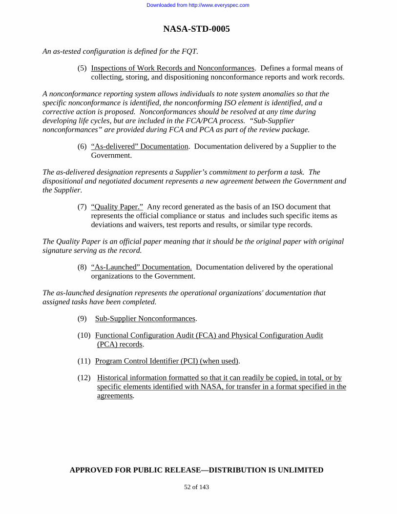
NASA-STD-0005
APPROVED FOR PUBLIC RELEASE—DISTRIBUTION IS UNLIMITED
52 of 143
An as-tested configuration is defined for the FQT.
(5) Inspections of Work Records and Nonconformances. Defines a formal means of collecting, storing, and dispositioning nonconformance reports and work records.
A nonconformance reporting system allows individuals to note system anomalies so that the specific nonconformance is identified, the nonconforming ISO element is identified, and a corrective action is proposed. Nonconformances should be resolved at any time during developing life cycles, but are included in the FCA/PCA process. “Sub-Supplier nonconformances” are provided during FCA and PCA as part of the review package.
(6) “As-delivered” Documentation. Documentation delivered by a Supplier to the Government.
The as-delivered designation represents a Supplier’s commitment to perform a task. The dispositional and negotiated document represents a new agreement between the Government and the Supplier.
(7) “Quality Paper.” Any record generated as the basis of an ISO document that represents the official compliance or status and includes such specific items as deviations and waivers, test reports and results, or similar type records.
The Quality Paper is an official paper meaning that it should be the original paper with original signature serving as the record.
(8) “As-Launched” Documentation. Documentation delivered by the operational organizations to the Government.
The as-launched designation represents the operational organizations' documentation that assigned tasks have been completed.
(9) Sub-Supplier Nonconformances.
(10) Functional Configuration Audit (FCA) and Physical Configuration Audit (PCA) records.
(11) Program Control Identifier (PCI) (when used).
(12) Historical information formatted so that it can readily be copied, in total, or by specific elements identified with NASA, for transfer in a format specified in the agreements.
Downloaded from http://www.everyspec.com

NASA-STD-0005
APPROVED FOR PUBLIC RELEASE—DISTRIBUTION IS UNLIMITED
53 of 143
4.4.3 Principle 4-1C “Provide controlled access to CSA information.”
4.4.3.1 Required Information System
a. The Supplier shall provide CSA information from existing internal information systems.
When information is required beyond the existing system, it will be provided through data automation portals for use by external organizations.
b. Supplier shall ensure that electronic entry and output are available to organizations for the purposes of collaborative engineering, collecting product information, and providing CSA reports.
c. The MIS used for CSA shall be secure and provide for controlled access.
d. Configuration status shall be available at all times and in real time for use by NASA and Supplier engineering teams supporting delivery, assembly, launch, and flight mission operations.
4.4.3.2 Location of CSA
a. The CMO shall control baselines and release engineering data to functional organizations.
b. The CMO shall also control CSA information and reports. c. If a Supplier is responsible for design, the Supplier shall designate the CMO as
responsible for the administration of the CSA. d. Aside from these controls, each CCB shall also establish a means of tracking and
recording associated change activity as a record of its own board activities.
4.4.3.3 Release System
a. The Supplier shall establish an Engineering Release System to issue configuration documentation to functional activities and to authorize the use of configuration documentation associated with an approved configuration.
b. The Release System shall maintain current and historical engineering release
information for all CIs and their corresponding component parts. c. Engineering release actions shall cite the authority for the release (ECP, CCBD,
contract letter, or Class II change).
Downloaded from http://www.everyspec.com

NASA-STD-0005
APPROVED FOR PUBLIC RELEASE—DISTRIBUTION IS UNLIMITED
54 of 143
d. The Engineering Release System shall be capable of defining product attributes and be in such a format as to allow recovery and review to ensure an actual match with actual built units.
(1) Specification Release and Approval: For NASA-controlled specifications, the Supplier shall submit the proposed specification by ECP to Program/Project/
Center for approval. NASA will review the ECP and specification and provide comments to the Supplier as necessary. Following incorporation of mutually agreed-to comments into the specification, the Supplier will be informed of ECP approval as specified in the contract. For ECPs that exceed prescribed contract limits or disagreements in terms, resolution will be negotiated through appropriate channels.
A. The Supplier shall release the specification and establish or revise the appropriate baseline.
If NASA prepares a specification, NASA will submit the specification and obtain Supplier agreement on implementation via appropriate procedures.
B. The Supplier shall release the Program/Project/Center-prepared specifications as part of the design baseline release.
Note: Initial submittals of specifications are required deliverables and do not require an ECP. However, the documents do require disposition by an approving authority; and changes may require negotiations between the Supplier and the Program/Project/Center.
(2) Engineering Release Information: Engineering release information releases new
or revised configuration documentation.
A. The Supplier shall utilize its own formats, systems, and procedures to the greatest extent possible to meet this requirement.
Each release identifies the data (documents/drawings/databases) released, the authorization for release, whether the release is an initial release or a change release, the CI or system affected (with effectivities), and date of release. B. This Standard does not specify standardized formats for an Engineering Release System; however, engineering release records shall be prepared and maintained in accordance with the minimum requirements stated in this Standard.
C. The formats, systems, and procedures may include information in addition to these minimum requirements, providing that the engineering release records conform to the following: (i) There shall be only one active release record for each drawing number.
Downloaded from http://www.everyspec.com

NASA-STD-0005
APPROVED FOR PUBLIC RELEASE—DISTRIBUTION IS UNLIMITED
55 of 143
(ii) Drawings previously released by a Sub-Supplier or Supplier other than the prime Supplier shall only be re-released after official design activity transfer.
(iii) The initial release of baseline engineering drawings, and all subsequent
changes, shall cite the authority for that release (e.g., ECP).
(3) Elements of Data Required for Hardware Items: NASA’s or the Supplier’s engineering release records for hardware items shall contain the following information:
A. CI Elements.
(i) Item number. (ii) Item serial number(s) (effectivity). (iii) Top drawing number. (iv) Item specification identification number.
B. Drawing Elements.
(i) Drawing number. (ii) Drawing title. (iii) CAGE code. (iv) Number of sheets. (v) Date of release. (vi) Drawing change or revision letter and release date of authorizing
document that directed the change or revision. (vii) Ancillary document numbers; e.g., engineering change notices,
engineering orders. (viii) Specification document, specification control drawing, or source control
drawing number.
C. Part Number Elements
(i) Controlling drawing number. (ii) Part numbers released.
Downloaded from http://www.everyspec.com

NASA-STD-0005
APPROVED FOR PUBLIC RELEASE—DISTRIBUTION IS UNLIMITED
56 of 143
(iii) Identification of change that created the part number.
(4) Elements of Data Required for Software Items: The engineering release records
shall reference the software CSCI VDD that contains the elements required in the data deliverables, and the guidance provided in IEEE/EIA 12207.1, Software Life Cycle Processes – Life Cycle Data.
(5) Production Release Functional Capabilities: To the extent that NASA or the
Supplier has detailed design responsibility, the release function (for documentation, drawings, and associated lists) shall be capable of determining the following released engineering requirements:
A. The composition of any part number at any level in terms of subordinate part
numbers. B. All next higher or next assembly part numbers in which the part is used. C. The composition of any software CSCI in terms of components and units
and subordinate item numbers. D. The CI number and serial numbers (effectivity) on which any subordinate
part is used. E. The Class I and Class II change identification numbers for engineering
change packages that have been partially or completely released for any part number or CI number and serial number.
F. The hardware CI numbers and serial numbers or software CSCI and version
numbers that constitute the effectivity of any change identification number. G. The Sub-Supplier, vendor, or Supplier part numbers which have been
assigned in response to critical component (item) specification documents, specification control drawings, or source control drawings issued by the Supplier.
H. The Supplier’s specification document, specification control drawings, or
source control drawing. I. Drawing numbers associated with any Sub-Supplier, vendor, or Supplier part
number.
Downloaded from http://www.everyspec.com

NASA-STD-0005
APPROVED FOR PUBLIC RELEASE—DISTRIBUTION IS UNLIMITED
57 of 143
(6) Release of Engineering Changes:
A. NASA’s or the Supplier’s release function and records shall be capable of identifying Class I and Class II engineering change packages.
B. The Supplier shall retain the record of superseded configuration requirements.
(i) Release Records:
(a) Release records shall identify all Class I and Class II engineering
releases accomplished under the authority of each Supplier CCB directive or equivalent.
(b) In addition, for all Class I changes, the ECP number shall be identified.
(i) Release Change Packages: All Class I and Class II engineering change
packages released for incorporation shall be completely implemented as directed before formal acceptance of the deliverable unit.
(7) Retention of CM Records:
A. The Supplier shall maintain records in accordance with the Records Plan (NASA Supplier) or the CMP as approved by the Program/Project/Center (see paragraph 4.1.9.1).
B. Under all circumstances, Suppliers shall retain records for the life of the program, unless otherwise dispositioned by the contractual authority or other authorized party.
(8) Field Release Functional Capabilities:
A. The Supplier shall maintain current the engineering data defining equipment that is under the jurisdiction of a NASA Center and may be progressing through testing or through activation programs.
B. The Supplier shall keep data current with all field activity requirements and releases.
(9) Data Distribution/Access:
A. Distribution statements shall be affixed by all document originators to technical data, prior to submittal for release, in accordance with the applicable laws and regulations.
B. Access to data shall be limited in accordance with the following:
Downloaded from http://www.everyspec.com

NASA-STD-0005
APPROVED FOR PUBLIC RELEASE—DISTRIBUTION IS UNLIMITED
58 of 143
(i) Applicable distribution statements (see paragraph 4.1.9.4).
(ii) Applicable data rights (see paragraph 4.1.9.4). (iii) Contract data requirements distribution. (iv) Security requirements. (v) Data status level (in-work, released, or archived) unless otherwise
specified in agreements (see paragraph 4.1.7).
4.4.4 Principle 4-2 “Data collection and information processing system requirements are determined based upon the need for configuration information.”
4.4.4.1 CSA Objectives
Imposing special requirements on a Supplier to obtain CSA information is discouraged; instead, the Government encourages the efficient use of existing information systems so long as the fundamental requirements are accomplished. The Quality Assurance (QA) organization and the associated MRB normally provide a parallel track of information regarding the “as built” configuration. An efficient CSA will provide capability for using these data to assist all technical disciplines participating in audits to analyze and verify build, inspections, and test.
a. The fundamental CSA requirements shall be the following: (1) Providing configuration status—tracking CM activity. (2) Disseminating approved and controlled documents, drawings, and data. (3) Making available design data and plans—serving as a repository of engineering
released data. (4) Making available reports and analysis regarding status of design baselines.
Table 3 provides guidance on CSA requirements and records and the associated products needed to achieve an effective CSA.
b. CSA products and requirements which fit specific program needs shall be defined by that program/project and implemented on Suppliers through contracts/agreements.
Downloaded from http://www.everyspec.com
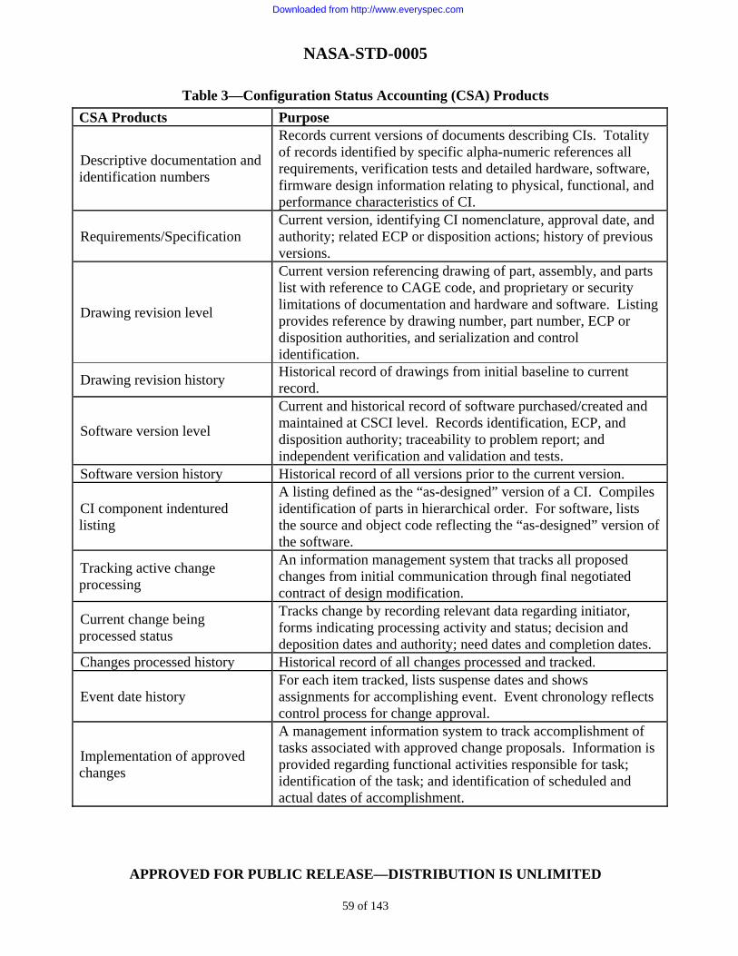
NASA-STD-0005
APPROVED FOR PUBLIC RELEASE—DISTRIBUTION IS UNLIMITED
59 of 143
Table 3—Configuration Status Accounting (CSA) Products
CSA Products Purpose
Descriptive documentation and identification numbers
Records current versions of documents describing CIs. Totality of records identified by specific alpha-numeric references all requirements, verification tests and detailed hardware, software, firmware design information relating to physical, functional, and performance characteristics of CI.
Requirements/Specification Current version, identifying CI nomenclature, approval date, and authority; related ECP or disposition actions; history of previous versions.
Drawing revision level
Current version referencing drawing of part, assembly, and parts list with reference to CAGE code, and proprietary or security limitations of documentation and hardware and software. Listing provides reference by drawing number, part number, ECP or disposition authorities, and serialization and control identification.
Drawing revision history Historical record of drawings from initial baseline to current record.
Software version level
Current and historical record of software purchased/created and maintained at CSCI level. Records identification, ECP, and disposition authority; traceability to problem report; and independent verification and validation and tests.
Software version history Historical record of all versions prior to the current version.
CI component indentured listing
A listing defined as the “as-designed” version of a CI. Compiles identification of parts in hierarchical order. For software, lists the source and object code reflecting the “as-designed” version of the software.
Tracking active change processing
An information management system that tracks all proposed changes from initial communication through final negotiated contract of design modification.
Current change being processed status
Tracks change by recording relevant data regarding initiator, forms indicating processing activity and status; decision and deposition dates and authority; need dates and completion dates.
Changes processed history Historical record of all changes processed and tracked.
Event date history For each item tracked, lists suspense dates and shows assignments for accomplishing event. Event chronology reflects control process for change approval.
Implementation of approved changes
A management information system to track accomplishment of tasks associated with approved change proposals. Information is provided regarding functional activities responsible for task; identification of the task; and identification of scheduled and actual dates of accomplishment.
Downloaded from http://www.everyspec.com

NASA-STD-0005
APPROVED FOR PUBLIC RELEASE—DISTRIBUTION IS UNLIMITED
60 of 143
Table 3—CSA Products (Continued)
CSA Products Purpose
Approved change implementation activities
Tracks information related to an approved change such as suspense, responsible individuals, and status of each pending action.
Documentation and drawing revisions activity
Tracks discrete events associated with preparation, approval, and disposition of data associated with a specific change.
Software revision activity Tracks discrete software events (coding, testing, etc.) associated with changes to the software product.
Retrofit/modification kit development
Tracks status of units not at manufacturing facility. Differentiates between field retrofit for items under Supplier control and under NASA control. Tracks in sufficient detail to identify difference among models (serial numbers) and to identify specific configuration of individual units (as-built).
As-built configuration (utilize, as much as possible, records from other organizations like quality, manufacturing, etc.)
Records exact configuration delivered to NASA. For hardware items, includes deviation or waiver from as-designed configuration; parts make up, including serial/lot number; engineering changes; design activity CAGE code; restrictions (such as licensing agreements, etc.). For software, records include complete version description (build, assemblage, problem reports). As built/As designed: Specifies deviations of “as built” from “as designed” baseline, including differences and rationale. Includes approved waivers and deviations.
Tracking audit action items Establishes an information management system to track action items resulting from audits such as functional and physical configuration audits.
Audit action item status
Records activity for each action issue opened during an audit and provides tracking and authorizing approvals for the close-out process, including review, coordination, and approval. Assigns necessary suspense dates.
Action item history Organizes historical records by CI, audit type, and other data retrieval schemes for each action item assigned.
4.4.4.2 CSA Analysis Requirements NASA Program/Project/Center or the Supplier has the responsibility to review and analyze CSA data.
a. When potential or actual problems/delinquencies that impact NASA are detected, the
Supplier or NASA shall coordinate within one business day to establish a course of action to rectify the situation.
Downloaded from http://www.everyspec.com

NASA-STD-0005
APPROVED FOR PUBLIC RELEASE—DISTRIBUTION IS UNLIMITED
61 of 143
b. In addition, the following shall be performed:
(1) Analysis to detect trends in the problems reported. (2) Corrective actions shall be evaluated to:
A. Verify that problems have been resolved, adverse trends have been reversed,
and changes have been correctly implemented in the appropriate processes and products.
B. Determine whether additional problems have been introduced.
4.4.4.3 Reporting Accomplishment of Retrofit Change Following a transfer of accountability between the Supplier and the Program/Project/Center, engineering changes may result in a decision to retrofit fielded equipment. The Program/Project/Center determines where equipment is to be retrofitted (either in the field or return to a designated factory or depot). The Supplier, using CSA, shall track retrofit installation of kits and confirm that installation has been verified and validated. Retrofit includes installation of a retrofit kit in the field. (Retrofit requires an update to equipment logs and the ADP.) 4.4.4.4 Reporting Location of Hardware and Software The Supplier CSA shall track location and movement of all hardware and software and be able to identify by CI number, model, serial and/or lot number, and location of all system components. 4.5 Configuration Verification and Audits
a. Configuration verification and audit processes shall ensure that configuration items have been properly identified, approved, released, and controlled throughout the Program/Project life cycle, that appropriate baselines have been established, and that the approved product configuration is reflected in the final product (i.e., “as built” matches “as designed” configuration). Configuration verification and audit is implemented through Periodic CM Process Audits and Functional Configuration Audits/Physical Configuration Audits (FCAs/PCAs).
b. Configuration audits shall be implemented as a joint activity.
Downloaded from http://www.everyspec.com

NASA-STD-0005
APPROVED FOR PUBLIC RELEASE—DISTRIBUTION IS UNLIMITED
62 of 143
c. NASA shall determine the respective roles and responsibilities for NASA organizations and Supplier organizations in the conduct of all configuration audits in accordance with the requirements of this Standard.
Note: The engineering or quality organization is usually responsible for the FCA since this audit is mostly concerned with verification.
4.5.1 Periodic CM Process Audits
a. Periodic CM process audits shall include the following elements: baseline control audits as defined in paragraph 4.2.11, and RFC/ECP audits and verification submittal audits as described below.
b. Audit activity involving the NASA CMO shall start after the establishment of the initial baseline of the FCD to ensure implementation of approved changes.
c. After the ACD is approved, the NASA CMO will audit to ensure implementation of approved changes into internal Supplier inspection, manufacturing, planning, and work descriptions.
d. After CDR, the NASA CMO will audit to ensure traceability of verification data submittals to the “as required” configuration tracked in the CSA.
Verification data is the recorded results of Supplier engineering efforts to test, inspect, demonstrate, analyze, or simulate CI designs to show compliance to the verification requirements. The specification version containing the verification requirement for the item/part “in test” or under inspection or under analysis must be verified as the correct version from the “as designed” product information. All of these audits have the goal of verifying to NASA Programs/Projects/Centers that Supplier CIs are qualified with respect to the following:
a. Correct specification requirements.
b. Accurate product information.
c. Accurate reflection of “as built” and “as tested” product information.
d. Inconsistencies and nonconformances are documented and resolved by the Supplier’s engineering organization.
e. Items offered for delivery to NASA are free of defects in meeting the baseline specifications and can be built from the product information with repeatability and assurance that the performance will be the same as those tested for qualification.
4.5.2 FCA/PCA
Principle 5-1 “Product attributes are verified by a systematic comparison with the results of associated product tests, analyses, inspections, demonstrations or simulation models.”
Downloaded from http://www.everyspec.com

NASA-STD-0005
APPROVED FOR PUBLIC RELEASE—DISTRIBUTION IS UNLIMITED
63 of 143
Principle 5-2 “Verify that a product’s design requirements are accurately reflected in the Product Definition Information.”
a. Before delivery of a CI to NASA, an FCA and a PCA shall be conducted following the guidelines in Appendix E of this Standard.
The FCA verifies that a product's requirement attributes have been met, and the PCA verifies that the product design meeting those attributes has been accurately reflected in the final product (i.e., “as built” matches “as designed” configuration).
b. As part of the FCA/PCA, the Supplier shall present the results of the Periodic CM Process Audits.
The FCA/PCA process is dependent on the NASA Supplier implementing robust verification, manufacturing, and quality processes that ensure that CIs are designed, built, and tested to the verification requirements in the baseline specifications, and that the product information for CIs accurately reflects the design physical attributes and other requirements in the baseline specifications engineering data sets or drawings.
c. The Supplier CMO shall implement management processes in the following areas to support successful FCA/PCA activities:
(1) Ensure Supplier management controls and Supplier management review of all data submitted to verify and show compliance with baseline requirements and prompt corrective action to resolve any nonconformances, or design or “as built” deficiencies.
(2) Ensure the recording and retention of all documentation involved in the evaluation and submittal of verification data to NASA for approval.
(3) Ensure definition of the appropriate roles for Supplier CMO, systems engineering, and quality organizations in the conduct of the FCA/PCA and comparison of the “as designed” to the “as built” and resolution of nonconformances.
4.5.3 Principle 5-3 “Maintain surveillance over the CM process to ensure that the process is adequately documented, that the process documentation is being followed and that the process execution is in compliance with requirements.”
This principle shall be met by the following:
(1) Ensure the incorporation of CM milestones and events in the project schedule.
(2) Ensure the independence of the CMO during CM audits and reviews.
(3) Ensure the acquisition of CM documentation and data for the project activities.
(4) Act promptly to resolve CM issues.
Downloaded from http://www.everyspec.com

NASA-STD-0005
APPROVED FOR PUBLIC RELEASE—DISTRIBUTION IS UNLIMITED
64 of 143
(5) Ensure the CMO development and execution of project CM surveillance planning.
Within NASA, CM surveillance includes FCA, PCA, and CM systems audits as defined in this section and in Appendix E.
5. GUIDANCE
5.1 Reference Documents The following reference documents are cited to give the user additional guidance or information. Reference documents may be cited within this Standard where guidance is specifically applicable to the stated requirement. Where the reference document is not called out in the text, the document provides information only. Citations herein will clearly indicate that the material is for information or guidance. 14 CFR 1214 Part 1214, Space Flight 48 CFR 1814 Acquisition of Commercial Items FAR Part 46.407 Quality Assurance, Nonconforming Supplies or Services Cited IEEE/EIA 12207.1 Software Life Cycle Processes – Life Cycle Data ISO/IEC TR15846 Technical Report Information Technology – Software Life Cycle Processes Configuration Management MIL-HDBK-61 Military Handbook, Configuration Management Guidance MIL-HDBK-965 Parts Control Program MIL-PRF-49506 Performance Specification Logistics Management Information MIL-STD-881 Work Breakdown Structures for Defense Material Items MIL-STD-975 NASA Standard Electrical Parts List IEEE 610.12 IEEE Standard Glossary of Software Engineering Terminology IEEE-STD-828 Software Configuration Management Plans IEEE 1042 Guide to Software Configuration Management GEIA-HB-649 Implementation Guide for Configuration Management GEIA-HDBK-859 Data Management Handbook
Downloaded from http://www.everyspec.com

NASA-STD-0005
APPROVED FOR PUBLIC RELEASE—DISTRIBUTION IS UNLIMITED
65 of 143
NPD 2200.1 Management of NASA Scientific and Technical Information (STI) NPR 1600.1 NASA Security Program Procedural Requirements NPR 2190.1 NASA Export Control Program These documents are listed as an aid to the reader to encourage comprehension of the details within. Much of the technical information contained in this Standard started as information from these documents. MIL-STD-973 Military Standard, Configuration Management (Cancelled) MSFC-STD-3394 Standard for Configuration Management for MSFC Programs/Projects.
5.2 Keyword Listing
The keyword listing is as follows:
Baselines Configuration Verification/Audit CM EIA-649 Configuration Accounting FCA Configuration Control PCA Configuration Identification
5.3 Supplemental Guidance for Configuration Management (CM) Planning
5.3.1 Computer-Automated Product Databases and Change Control Systems
Configuration documentation can be transferred as hard copy or as electronic data files. Access may be interactive through an integrated technical information tool. The Program/Project/ Center’s planning will address all CM technical data requirements of the Supplier (including data handling, processing, storage, integrity, transfer, security, and maintenance) for the performance period specified in the contract or agreements.
5.3.2 Exchange of Technical Data
NASA Programs/Projects/Centers and NASA Suppliers will provide engineering data interoperability and exchange of electronic technical data between all elements of the NASA program. The use of EIA-836 or other standards is encouraged for exchange of CM data.
5.3.3 Automated Processing and Submittal of Data
To facilitate the processing of submitted data, NASA projects will use automated processing and electronic submittal techniques such as the following:
Downloaded from http://www.everyspec.com

NASA-STD-0005
APPROVED FOR PUBLIC RELEASE—DISTRIBUTION IS UNLIMITED
66 of 143
a. When data is submitted by electronic transfer (e.g., modem) to NASA, acknowledgment of receipt will be generated at the end of the transmission. When data is electronically transferred by NASA to the Supplier, acknowledgment of receipt by the Supplier will be generated at the end of the transmission. The Supplier will implement a method of error detection for data transfer to ensure deliverable data products are capable of being re-created in Human Readable Format (HRF).
b. The Supplier will maintain the current status (working, released, submitted, and approved) of all digital technical data in the database at all times. Any data electronically transferred by the Supplier to NASA will be so identified. c. The Supplier has the responsibility to implement procedures to identify and control data during the Supplier and NASA review cycle. As a minimum, these procedures will address:
(1) Identification of data files submitted to NASA for review, annotation, comment, and disposition, as applicable, in accordance with NASA-specified review and approval requirements. Each submitted digital data file will have a unique identifier that will indicate file version and submitted status. To ensure file integrity, the file must distinguish an altered (annotated or redlined) file version from the originally submitted file version.
(2) How data and changes are transmitted. (3) How changes from previous versions are indicated. (4) Notification/acknowledgment of receipt, return, or acceptance. (5) Indication of time constraint, if any, for automatic data acceptance. (6) Data status accounting.
5.3.4 Interactive Access to Digital Data
In addition to the above requirements, the Supplier’s integrated technical information service will, where specified, accommodate the predefined query and extraction of data. The integrated technical information service should implement procedures that define the control of databases and files during NASA's and the Supplier’s interactive review and update cycles. As a minimum, the following will be defined:
a. How data is to be accessed.
b. Request for access and logging of access for read-only or annotation.
c. Naming of temporary working version of the file(s) for purpose of annotation/mark up.
d. Means of indicating whether a comment/annotation is essential/suggested.
Downloaded from http://www.everyspec.com

NASA-STD-0005
APPROVED FOR PUBLIC RELEASE—DISTRIBUTION IS UNLIMITED
67 of 143
e. Re-identification of redlined versions, as required.
f. Method of indicating acceptance, provisional acceptance, approval, or rejection, as applicable.
g. Time constraints, if any, on data acceptance (e.g., automatic approval) by any links in the Supplier’s or NASA's review and approval chains.
h. Automated status accounting, including tracking of disposition of required changes.
i. Re-identification of changed files.
5.3.5 Principle 1-9 “Plan for long-term data preservation by addressing the information technologies used to store, retrieve, and interpret data.”
5.3.5.1 Implications of Draft Handbook GEIA-HB-649
Two major aspects to this principle are the backup/preservation of current “active” electronic files to protect against damage to or destruction of the primary active data repository and archiving of data that is no longer currently used but should be kept for historical purposes. The preservation of active data requires that backup copies of the current versions of electronic files be generated at specific time intervals (hourly, daily, weekly, or monthly) depending on the importance and volatility of the content of the files. Archive labeling should include data format so that archaic formats can be readily identified for storage technology assessments. A specific number of these backups will be retained in a safe storage area remote from the location where the master files are retained. As the product matures and is planned for use over a number of years, the enterprise needs to consider the length of time the associated information (i.e., both current active files and archived historical files) retains value and how long that information needs to be stored by anticipating that technologies will change over time. Changing technologies can potentially render certain types of data unusable unless provision is made for periodic assessment of the technologies. When addressing data preservation, the enterprise must consider the life cycles of the product, the IT applications used to interpret and host the data, and the storage media.
5.3.5.2 Implications of GEIA-859, Data Management Standard, and Draft Handbook 859 Excerpts
Any data assets that are of potential business, project, operational, or historic value will be retained until the value is depleted. Data of sustained value to the enterprise will be retained and evaluated on an ongoing basis as a part of the DM process. Data assets will, upon the creation and initial storage, have planned retention requirements identified and documented. Such business processes would address archive formats, frequency of reviews, purge planning, disposition funding, hardware and software migration methods and schedules, and related activities.
Downloaded from http://www.everyspec.com
NASA-STD-0005
APPROVED FOR PUBLIC RELEASE—DISTRIBUTION IS UNLIMITED
68 of 143
5.4 Supplemental Guidance for Configuration Management (CM) Identification
5.4.1 Developmental Configurations
NASA projects should establish and implement a developmental CM process for both hardware and software. This process should be used to control the documentation and repositories containing the elements of the developmental configuration. Each increment of development should be compatible with all requirements in this Standard. This process should be defined in the CMP. Also, the point at which the development configuration process is terminated should be defined in the CMP and should not be later than the establishment of the product baseline.
5.4.1.1 Correction of Design Problems
As expected during development, some configurations of CIs do not meet all of the requirements. This problem should show up early as a problem in form, fit, or function. To improve the design and meet the top-level requirements, the Supplier should have leeway to redesign.
5.4.1.2 Tracking of Design Problems
In this case, the Supplier should prepare a problem/change report to describe each problem detected in hardware, software, or documentation that has been placed under internal configuration control. The problem/change report should describe the corrective action needed and the actions taken to resolve the problem. These reports should serve as input to the corrective action process.
5.4.1.3 Redesign The Supplier should implement a corrective action process for handling all problems detected in the products under internal configuration control. The corrective action process should ensure that all detected problems are promptly reported, action is initiated, resolution is achieved, status is tracked and reported, and records of the problems are maintained in accordance with NPR 1441.1.
5.4.1.4 Update of Developmental Product Information
Once the redesign is verified, the Supplier should update the product information data to provide a record of the new configuration. Configuration documentation should be released.
5.4.2 Documentation Library
The Supplier should establish a documentation library and implement procedures for controlling the documents residing within the documentation library for all developmental configurations. This library should be available to flight test teams and test personnel when the system is in integrated testing at a test facility.
Downloaded from http://www.everyspec.com

NASA-STD-0005
APPROVED FOR PUBLIC RELEASE—DISTRIBUTION IS UNLIMITED
69 of 143
5.4.3 Drawing Library
The Supplier should establish a drawing library and implement procedures for controlling the drawings, Computer-Aided Design (CAD), and Computer-Aided Manufacturing (CAM) instructions residing within the drawing library. This library should be available to flight test teams and test personnel when the system is in integrated testing at a test facility.
5.4.4 Software Development Library
The Supplier should establish a Software Development Library (SDL) and implement procedures for controlling the software residing within the SDL. This library should be available to flight test teams and test personnel when the system is in integrated testing at a test facility.
5.5 Supplemental Guidance for Configuration Control
The ECP preparation guidelines are contained in Appendix D.
5.5.1 Engineering Change Process
The Supplier should include the following elements in the configuration control process:
a. Determination of a need for the change.
b. Establishment by the Supplier of a classification of the engineering change as Class I or Class II.
c. Review and evaluation of the change.
d. Disposition of the change.
e. Preparation of an ECP.
f. Submittal of the ECP to NASA.
g. Incorporation of approved (or concurred) engineering changes in the documentation, including, when applicable, negotiation into the agreement.
h. Implementation of the change in accordance with the contract/agreement.
Note: Similar steps should apply to RFDs and RFWs.
5.5.2 Change Classification
For purposes of configuration control, changes should be classified as Class I or Class II, depending upon the impact of the change on established configuration baselines or other requirements specified in the agreements. Change classification definitions and submission requirements are stated in the following paragraphs.
Downloaded from http://www.everyspec.com

NASA-STD-0005
APPROVED FOR PUBLIC RELEASE—DISTRIBUTION IS UNLIMITED
70 of 143
5.5.2.1 Class I Change The submitter should designate a proposed change as Class I when any of the baseline factors listed in Table 4 are impacted. The Supplier should submit all Class I changes to the NASA Contracting Officer. The Supplier should not implement a Class I change without specific direction from the NASA Contracting Officer or NASA customer as defined by the agreement. 5.5.2.2 Class II Change
When the proposed change does not qualify as a Class I change, the submitter should designate the proposed change as Class II. The Supplier should process, disposition, and implement Class II changes within the Supplier’s CM system. Concurrent with internal processing, the Supplier should submit copies of all Class II changes to the responsible NASA Project CCB, or its designated representative, for concurrence with the classification. In the case of a notification of nonconcurrence with the classification, the Supplier resubmits the change as a Class I change.
5.5.3 Level of Change Approval Authority
The level of change approval authority (Class I and Class II engineering changes) is often determined by the classification, complexity, risk, or cost of the change. The change approval authority for low-cost/low-risk changes is commonly assigned to lower-level management. However, as the cost and risk of proposed changes increase, the level of change authority transitions to individuals with greater management and fiscal responsibility because the change is more widespread and has a greater impact. The level of change authority should be shown in the CMP.
5.6 Supplemental Guidance for Configuration Status Accounting (CSA)
Project offices should conduct CM systems reviews to assess the CM accounting system being used to support the Project. These reviews should include the accounting process down to the CI and parts levels. Paragraph 4.4 of this Standard should be the basis of the assessment. Periodic assessments are necessary to obtain reliable, accurate accounting CSA information that is useful to managing the project.
Downloaded from http://www.everyspec.com

NASA-STD-0005
APPROVED FOR PUBLIC RELEASE—DISTRIBUTION IS UNLIMITED
71 of 143
Table 4 – Class I Change Definition
Functional Baseline Allocated Baseline Product Baseline
(1) Approved program/project specification or equivalent.
(2) Software Requirements Specification. (3) Interface characteristics/ Documents. (4) Safety (5) Other imposed technical
requirements definition document. (6) Imposed or “agreed to” price, fee,
guarantees, or schedules.
(1) Through (6) Same as functional baseline.
(7) Approved specification(s).
(8) Imposed qualification and acceptance verification requirements.
(9) Qualification status previously
accepted by NASA. (10) NASA-furnished equipment. (11) Specified critical processes. (12) Change of vendors
of engineering critical components.
(13) Retrofit. (14) Software Design requirements
specification(s). (15) Software Interface requirements.
(1) Through (15) Same as functional and allocated baseline.
(16) Change to approved product
baseline documentation if any of the following are affected:
(a) Interchangeability,
substitutability, or replace-ability as applied to CIs (hardware & software), and to all subassemblies and parts except the pieces and parts of nonrepairable subassemblies.
(b) Operation, test/checkout,
logistics, maintenance documentation, or computer software.
(c) Compatibility with support
equipment, trainers, training devices/equipment.
(d) Preset adjustments or schedules
affecting operating limits or performance to such an extent as to require assignment of a new identification number.
(e) Electrical interference to
communications – electrical equipment or electromagnetic radiation hazards.
(f) Functional or performance
characteristics demonstrated or experienced in previously delivered articles.
(g) Electromagnetic characteristics. (h) Responsibilities of other
program elements. (17) Software Detail design
specification(s) – “As-Built.”
Downloaded from http://www.everyspec.com

NASA-STD-0005
APPROVED FOR PUBLIC RELEASE—DISTRIBUTION IS UNLIMITED
72 of 143
5.7 Supplemental Guidance for Verification/Audits
Appendix E provides the guidelines for accomplishing a formal FCA and PCA. NASA Programs/Projects/Centers and NASA Suppliers should develop detailed plans for conducting FCAs and PCAs. These plans should be integrated into the SEMP and the Quality Plan for the project. NASA Programs/Projects should perform a program risk analysis prior to any decision to propose the deletion of the requirement to conduct of FCAs and of PCAs and request deviation from the requirements of paragraph 4.5 of this Standard. Verification of the design and closure of action items involving verification issues are primary functions of the project during these activities. Project office systems engineering, CM, and quality organizations all have important roles during these assessments.
NASA Programs/Projects/Centers should plan carefully for the resources to accomplish a thorough FCA and PCA. The project office should make an early decision on the level of hardware and software assemblies for which the FCA and PCA should be accomplished. In some situations, the project office may desire to conduct the reviews and audits using project resources. In other situations, the project office may direct the Supplier to conduct the reviews and then audit the results.
Downloaded from http://www.everyspec.com

NASA-STD-0005
APPROVED FOR PUBLIC RELEASE—DISTRIBUTION IS UNLIMITED
73 of 143
APPENDIX A
ACRONYMS AND DEFINITIONS
A.1 Purpose/Scope
This Appendix defines the acronyms and terms utilized in this Standard. NASA projects are discouraged from tailoring the use of these acronyms and definitions. A.2 Acronyms
ACD Allocated Configuration Documentation
ACSN Advanced Change Study Notice
ADP Acceptance Data Package
ANSI American National Standards Institute
AR Acceptance Review
ASME American Society of Mechanical Engineers
ATP Authority to Proceed
CAD Computer-Aided Design
CAGE Commercial and Government Entity
CAM Computer-Aided Manufacturing
CCB Configuration Control Board
CCBD Configuration Control Board Directive
CDR Critical Design Review
CI Configuration Item
CM Configuration Management
CMO Configuration Management Organization
CMP Configuration Management Plan
COTS Commercial Off-the-Shelf
CPIN Computer Program Identification Number
CR Change Request
Downloaded from http://www.everyspec.com

NASA-STD-0005
APPROVED FOR PUBLIC RELEASE—DISTRIBUTION IS UNLIMITED
74 of 143
CSA Configuration Status Accounting
CSC Computer Software Component
CSCI Computer Software Configuration Item
CSU Computer Software Unit
DAR Deviation/Waiver Approval Request
DCN Document Change Notice
DFRC Dryden Flight Research Facility
DLA Defense Logistics Agency
DLAH Defense Logistics Agency Handbook
DM Data Management
DoD Department of Defense
DPM Direct Part Marking
DVD Digital Video Disc
EAR Export Administration Regulations
ECP Engineering Change Proposal
EEE Electrical, Electronic, and Electromechanical
EIA Electrical Industries Alliance
ERR Engineering Release Record
FAR Federal Acquisition Regulations
FCA Functional Configuration Audit
FCD Functional Configuration Documentation
FQT Formal Qualification Test
FRR Flight Readiness Review
GEIA Government Electronics and Information Technology Association
GFE Government-Furnished Equipment
GFP Government-Furnished Property
GRC Glenn Research Center
GSFC Goddard Space Flight Center (NASA)
Downloaded from http://www.everyspec.com

NASA-STD-0005
APPROVED FOR PUBLIC RELEASE—DISTRIBUTION IS UNLIMITED
75 of 143
H/W Hardware
HB Handbook (GEIA)
HDBK Handbook
HRF Human Readable Format
HWCI Hardware Configuration Item
ICD Interface Control Document
ICWG Interface Control Working Group
IEEE Institute of Electrical and Electronics Engineering
ILS Integrated Logistics Support
IRD Interface Requirements Document
IRN Interface Revision Notice
ISO International Organization for Standardization
ISS International Space Station
IT Information Technology
ITAR International Traffic in Arms Regulations
ITP Information Technology Planning
JPL Jet Propulsion Laboratory
JSC Johnson Space Center
KSC Kennedy Space Center
LaRC Langley Research Center
LMCO Lockheed Martin Co.
MIL Military
MIS Management Information System
MRB Material Review Board
MSFC Marshall Space Flight Center
NASA National Aeronautics and Space Administration
NDIA National Defense Industrial Association
NID NASA Interim Directive
Downloaded from http://www.everyspec.com

NASA-STD-0005
APPROVED FOR PUBLIC RELEASE—DISTRIBUTION IS UNLIMITED
76 of 143
NOR Notice of Revision
NPD NASA Policy Directive
NPR NASA Procedural Requirement
NSN National Stock Number
OCIO Office of the Chief Information Officer
P/N Part Number
PCA Physical Configuration Audit
PCD Product Configuration Documentation
PCI Program Control Identifier
PDI Preserving Digital Information
PDR Preliminary Design Review
PIN Part Identification Number
PIRN Preliminary Interface Revision Notice
PPSL Program Parts Selection List
QA Quality Assurance
RFC Request for Change
RFD Request for Deviation
RFW Request for Waiver
S/N Serial Number
S/W Software
SBU Sensitive But Unclassified
SCMP Software Configuration Management Plan
SCN/DCN Specification Change Notice/Document Change Notice
SDL Software Development Library
SDO Standards Developing Organizations
SEMP Systems Engineering Management Plan
SRB Software Review Board
SRD Systems Requirements Definition
Downloaded from http://www.everyspec.com

NASA-STD-0005
APPROVED FOR PUBLIC RELEASE—DISTRIBUTION IS UNLIMITED
77 of 143
SRR System Requirements Review
SSC Stennis Space Center
SSTO Single Stage-to-Orbit
STD Standard
STI Scientific and Technical Information
TBE Teledyne Brown Engineering
TWG Topic Working Group
UID Unique Identification Designation
VDD Version Description Document
WBS Work Breakdown Structure A.3 Definitions Definitions of common words may be found in Webster’s Third New International Dictionary (unabridged). The following definitions are unique to CM or defined in the context of the CM environment and are provided to prevent misunderstanding of the intent and content of the standard. The reader should refer to NPR 7120.5 for additional definitions peculiar to the NASA environment. Agreement: Any “meeting of the minds” that results in a requirement for a NASA system to be designed, delivered, and operated for a specific NASA mission or purpose. This agreement can take many forms, such as a contract under the FAR, a commercial contract, a cooperative agreement, a grant, or other such instrument as defined and approved by NASA. Application Environment: The set of conditions in which the product is designed for use. Approval: Authorization from a designated authority that a product, process, or information is complete and suitable for use. Approved: Within the context of CM: A state signifying approval of a proposed or completed action, or of a process, or of a particular document/data. (See also Disapproved.) Archived Information: Information that has been retained for historical purposes and that can be retrieved and is usable over the time designated for retention. Attributes: See “Product Attribute(s).” Baseline: See “Configuration Baseline.”
Downloaded from http://www.everyspec.com

NASA-STD-0005
APPROVED FOR PUBLIC RELEASE—DISTRIBUTION IS UNLIMITED
78 of 143
Block Change Concept: For hardware CIs, an engineering change implementation concept that designates a number (i.e., a block) of consecutive production units of the CI to have an identical configuration on delivery and in operation. Use of this concept production run is divided into "blocks" of units. The production incorporation point for a proposed ECP is delayed to coincide with the first unit of the next block, or retrofit is required at least for all units of the current block already delivered. For computer software CIs, once the product baseline has been established, the concept requires the accumulation and the simultaneous implementation of several routine software changes to minimize the number of interim versions and related documentation. Change: See “Configuration Change.” Commercial and Government Entity (CAGE) Code: A five-character code, listed in Cataloging Handbook H4/H8, which is assigned to commercial and government activities that manufacture or develop items, or provide services or supplies for the Government. When used with a drawing number or part number, the CAGE code designates the design activity that the drawing or part number is assigned. Compatibility ECP: An ECP prepared to achieve consistency in the baseline. Compatibility ECP is required when changes to either the hardware or software product result in incompatibility with support equipment, trainers, or training devices/equipment. The compatibility ECP assures that changes, to one CI that affects another CI or CSCI, are accomplished to maintain consistent Functional, Allocated, and Product baselines, including testing and operational requirements. Computer Database: See “Database.” Computer Software: See “Software.” Configuration:
a. The product attributes of an existing or planned product, or a combination of products. b. One of a series of sequentially created variations of a product.
Configuration Activities: The series of tasks defined in CMP and CM Procedures that are accomplished by CM organizations to implement this Standard. Configuration Audit: The CM function that reviews processes and products to validate compliance with requirements and verifies that products have achieved the required attributes and conform to released product definition information. Configuration audits may be divided into separate functional and physical configuration audits. Configuration Baseline: Approved information that identifies and establishes the attributes of a product at a point in time and serves as a basis for defining change.
Downloaded from http://www.everyspec.com

NASA-STD-0005
APPROVED FOR PUBLIC RELEASE—DISTRIBUTION IS UNLIMITED
79 of 143
a. Baseline: The technical requirements of a program/project/CI as approved by the responsible CCB at a specific time during the life cycle and recorded in a configuration identification document or set of documents and all approved changes. There are three basic NASA baselines as indicated below:
(1) FCD: NASA Programs/Centers/Organizations generate the documentation required for the Functional Baseline. The FCD should be in the form of a specification for a system, plus other applicable documentation (for example, interface requirements specifications and ICDs for the system). For programs involving the development of a single CI, a system specification should not be generated; however, the end-item specification should be used for the FCD. The FCD should also identify the configuration documentation for selected items that are to be integrated or interfaced with the CI, such as items separately developed or currently in the inventory. The functional baseline is the approved functional configuration documentation.
(2) ACD: NASA Programs/Centers/Organizations generate the documentation
required for the Allocated Baseline. The ACD should define requirements allocated from the FCD or from a higher-level CI to a lower-level CI. The ACD for the CI should be in the form of an item or software requirements specification and other referenced documentation (for example, ICDs, Interface Requirements Specifications item or software requirements specifications for lower-level CI(s), if any). For programs involving the development of a single CI, the CI specifications may serve as both the functional or allocated baselines. The allocated baseline is the approved allocated configuration documentation.
(3) PCD: NASA Programs/Centers/Organizations generate the documentation
required for the Product Baseline. The PCD should be in the form of an item, software, material and process specifications, engineering drawings, software listings, software design documentation, military specifications, and other technical documentation composing a complete technical data package for the CI. The PCD may also be in the form of the actual equipment or software media or both. The PCD should prescribe the necessary physical and functional characteristics of the CI and the verifications required to demonstrate required performance. The product baseline is the approved product configuration documentation.
Configuration Change: An alteration to a product or its product configuration information or both. Configuration Change Management: The CM function that ensures changes to a configuration baseline are:
a. Identified properly, recorded, evaluated, approved or disapproved.
b. Incorporated.
c. Verified as appropriate.
Downloaded from http://www.everyspec.com

NASA-STD-0005
APPROVED FOR PUBLIC RELEASE—DISTRIBUTION IS UNLIMITED
80 of 143
Configuration Control Board: A collection of mission personnel who act to review and evaluate configuration changes proposed against mission products; not a voting entity, has formal records, issues direction to enterprise organizations for implementation of configuration changes, chaired by management authority in accordance with a defined charter, staffed by CMO personnel who provide administrative function; controls engineering release authority. Configuration Documentation: The technical documentation that identifies and defines the item's functional and physical characteristics. The configuration documentation is developed, approved, and maintained through three distinct levels of detail. The three levels of configuration documentation are the functional configuration documentation, the allocated configuration documentation, and the product configuration documentation. Configuration Identification: The CM function which:
a. Establishes a structure for products and product configuration information.
b. Selects, defines, documents, and baselines product attributes.
c. Assigns unique identifiers to each product and product configuration information.
Configuration Identification Numbers: Numbers that, individually or in combination, permit accurate selection of the configuration required to perform a given function. These numbers may include:
a. Specification identification numbers. b. CI numbers. c. Drawing and part numbers. d. Engineering change identification numbers. e. CAGE code numbers. f. Serial numbers. g. Lot numbers.
Configuration Management (CM): A process that establishes and maintains consistency of a product’s attributes with the requirements and product configuration information throughout the product’s life cycle. Configuration Management Organization (CMO): The functional organization chartered to define, plan, and execute CM principles and requirements. This office provides continuing service to NASA Programs/Projects/Centers and Supplier management organizations. When used in this Standard, CMO refers to a collaborative effort between NASA Programs/Projects/Centers and Suppliers. Unless the task being described is clearly a function of the Program/Project/Center CMO, the imperative “shall” is used to ensure implementation of the requirement by the Supplier’s CMO.
Downloaded from http://www.everyspec.com

NASA-STD-0005
APPROVED FOR PUBLIC RELEASE—DISTRIBUTION IS UNLIMITED
81 of 143
Configuration Status Accounting (CSA): The CM function managing the capture and maintenance of product configuration information necessary to account for the configuration of a product throughout the product’s life cycle. Configuration Verification: The CM function that ascertains that a product has achieved consistency and accuracy of the product requirements and product configuration information. Customer: The individual or organization with the need for the system, who has the resources to acquire the system, and who is party to the agreements for the acquisition. Data: Recorded information, regardless of medium or characteristics, of any nature, including administrative, managerial, and technical. Database: A collection of related data generally stored in the form of electronic media. Data Element (Software/Firmware): A single piece of information, the smallest unit normally residing in a computer system (database). A record consists of one or more data elements. Deficiencies:
a. Conditions or characteristics in any item that are not in accordance with the item's current approved configuration documentation; or
b. Inadequate (or erroneous) item configuration documentation that has resulted, or may
result, in units of the item that do not meet the requirements for the item. Design Change: See “Engineering Change.” Design Information: Technical information resulting from translating requirements for a product into a complete engineering description of the product. See “Product Definition Information.” Developmental Configuration: The Supplier design and associated technical documentation that defines the evolving configuration of a CI during development. The configuration is under the developing Supplier’s configuration control and describes the design definition and implementation. The developmental configuration of a CI consists of the Supplier’s released hardware and software designs and associated technical documentation. Deviation: A documented authorization releasing a program or project from meeting a requirement before the requirement is put under configuration control at the level the requirement will be implemented. Disapproved: Conclusion by the appropriate authority that a product, a process, or information is incomplete or unsuitable for its intended use. (See also Approved.)
Downloaded from http://www.everyspec.com

NASA-STD-0005
APPROVED FOR PUBLIC RELEASE—DISTRIBUTION IS UNLIMITED
82 of 143
Document: Information and its support medium; e.g., record, specification, drawing, report, standard. Note that the medium may be paper, photograph, digital files, optical computer disc, magnetic, electronic storage (digital documents), or a combination. Effectivity: Within NASA: The identification of the number of products, within a given set of products in production or delivered status, that are to be changed as a result of a CCB action to implement changes in a particular group of products (CIs). An Effectivity designation defines the range within a set of CIs or an event (like a unique mission identification) to which a particular configuration change applies. The range is expressed as serial numbers, or lot numbers, or model designations. Events are usually expressed as alpha-numeric values defined by the Program. Engineering Change: A change to the current approved configuration of a CI at any point in the life cycle of the item. Engineering Change Justification Code: A code which indicates the reason for a Class I engineering change. Engineering Change Package: A set of indexed technical information or technical data for a single unique Engineering Change as submitted as an attachment to an ECP or Class I Engineering Change. Engineering Change Priorities: The priority (e.g., emergency, urgent, routine) assigned to a Class I engineering change which determines the relative speed at which the Engineering Change Proposal is to be reviewed, evaluated, and, if approved, ordered, and implemented.
Engineering Change Proposal (ECP): A proposed change to the engineering of a product, and the documentation by which the change is described, justified, and submitted. ECPs address the scope of the change with respect to the whole product and its systems.
Engineering Change Proposal Types: A term covering the subdivision of Class I Engineering Change Proposals on the basis of the completeness of the available information delineating and defining the engineering change. The type is identified as preliminary or formal. Engineering Release: An action whereby configuration documentation or an item is officially made available for the intended use. Engineering Release Record (ERR): The single, authoritative record identifying released documentation including approved changes. Engineering Release System: The single, authoritative control system for assigning document numbers, verifying requirements, recording and transmitting engineering documentation required for fabrication, assembly, installation, and test of program hardware and software. The Engineering Release System controls the dissemination of engineering data by physical means. Evaluation: The process of determining whether an item or activity meets specified criteria.
Downloaded from http://www.everyspec.com

NASA-STD-0005
APPROVED FOR PUBLIC RELEASE—DISTRIBUTION IS UNLIMITED
83 of 143
Firmware: The combination of a hardware device and computer instructions or computer data that resides as read-only software on the hardware device. Fit: The ability of a product to interface or interconnect with, or become an integral part of, another product. Form: The shape, size, dimensions, and other physically measurable parameters that characterize a product. Function: The action or actions that a product is designed to perform. Functional Attributes: Measurable performance parameters. These are expressed in terms of quantitative parameters; e.g., speed, range, weight including the respective tolerances where applicable. Ground Support: Non-flight systems, equipment, computer software, or devices (with a physical or functional interface with flight hardware) necessary to routinely support the operations of transporting, receiving, handling, assembly, inspection, test, checkout, servicing, and launch of space vehicles and payloads at launch, landing, or retrieval sites. Group Identifier: An alpha-numeric identifier (e.g., lot), that does the following:
a. Uniquely identifies a group of like units of the same product that are manufactured or assembled under uniform conditions and are expected to function in a consistent manner.
b. Uniquely designates a specific volumetric quantity (batch) of a material (usually a
chemical mixture) created at the same time and expected to have properties similar to, but not necessarily the same as, other batches created at other times. Hardware: Products and the product components, e.g., mechanical, electrical, electronic, etc. Hardware Configuration Item (HWCI): A configuration item that is hardware. Incremental Development: In this process, a desired capability is identified, an end-state requirement is known, and that requirement is met over time by developing several increments, each dependent on available mature technology. Installation Notice Card: The official document used after delivery to update the CM system and to inform the procuring activity and the developer that a particular modification package has been installed, tested, verified, and accepted in accordance with its associated change instruction. Interchangeable: A product that can be exchanged with another product that has equivalent or similar essential product attributes without alteration of the products themselves, or of adjoining products, except for adjustment.
Downloaded from http://www.everyspec.com

NASA-STD-0005
APPROVED FOR PUBLIC RELEASE—DISTRIBUTION IS UNLIMITED
84 of 143
Interface: The product attributes that exist at a common boundary between two or more products. Interface Control: The process of identifying, recording, and managing product attributes at the common boundary between two or more products provided by one or more organizations. Interface Revision Notice (IRN): A form used to record approved changes to baseline interface documents. Life Cycle: A generic term covering all phases of acquisition, operation, and logistics support of an item, beginning with the concept definition and continuing through disposal of the item. Life-Cycle Cost: The total cost of acquisition and ownership of that system over its life cycle. It includes the cost of development, acquisition, support, and where applicable, disposal. Manufacturer's Code: See “Commercial and Government Entity (CAGE) code.” Material: A generic term covering systems, equipment, stores, supplies, and spares including related documentation, manuals, computer hardware, and software. Model: In addition to the conventional dictionary definition: a model is a design solution, with appropriate configuration descriptions, for a systems technical requirement of sufficient detail that its performance may be accurately predicted by applied physics. “Models” in the NASA environment are systems configurations that may be the result of conceptual design activities to meet a single set of mission requirements. A collection of models that all meet the same mission requirements are differentiated by “Model Numbers” with revisions that indicate an installed difference in configuration. There are four types of models: “Exploratory Development Model,” “Advanced Development Model,” “Engineering Development Model,” and a “Production Model”; the definitions are found in the Global Drawing Requirements Manual (DRM). The model numbers are aids in identification of design solutions in trade-off studies. NASA Payload: Any payload for which NASA has design, development, test, or operations responsibility. Nomenclature:
a. Names assigned to kinds and groups of products. b. Formal designations assigned to products by customer or Supplier; e.g., model number
or model type, design differentiation, specific design series, or configuration. Nonconformance: The failure of a unit or product to conform to specified requirements.
Downloaded from http://www.everyspec.com

NASA-STD-0005
APPROVED FOR PUBLIC RELEASE—DISTRIBUTION IS UNLIMITED
85 of 143
Non-developmental Item: Non-developmental item is a broad generic term that covers material available from a wide variety of sources with little or no development effort required by the Government. Non-recurring Costs: As applied to ECPs, these are one-time costs, which will be incurred if an engineering change is approved and which are independent of the quantity of items changed, such as cost of redesign, special tooling, or testing. Notice of Revision (NOR): A document used to define revisions to drawings, associated lists, or other referenced documents that require revision after engineering change proposal approval. Part Number or Name: See “Product Identifier.” Performance: A quantitative measure characterizing a physical or functional attribute relating to the execution of an operation or function, e.g., quantity (how many or how much), quality (how well), coverage (how much area, how far), timeliness (how responsive, how frequent), and readiness (availability, mission/operational readiness). Payload: Any airborne or space equipment or material that is not an integral part of the carrier vehicle (i.e., not part of the carrier aircraft, balloon, sounding rocket, expendable or recoverable launch vehicle). Included are items such as free-flying automated spacecraft, Space Shuttle payloads, Space Station payloads, expendable launch vehicle payloads, flight hardware and instruments designed to conduct experiments, and payload support equipment. Physical Attributes: Quantitative and qualitative expressions of material features; e.g., composition, dimensions, finishes, form, fit, and the respective tolerances. Preliminary Interface Revision Notice (PIRN): An IRN form used to describe proposed changes to IRDs/ICDs by participating developers or design agencies. Product: Something that is used or produced to satisfy a need or is the result of a process (e.g., documents, facilities, firmware, hardware, materials, processes, services, software, or systems). Product Attribute(s): Performance, functional, and physical characteristic(s) of a product. Product Configuration Information: Information about a product consisting of product definition information and product operational information. Product Definition Information: Information that defines the product requirements, documents the product attributes, and is the authoritative source for configuration definition and control. Product Identifier: A name or alpha-numeric identifier, unique to the issuing organization, used to designate products, e.g., parts and assemblies of the same configuration, and to differentiate them from other products.
Downloaded from http://www.everyspec.com

NASA-STD-0005
APPROVED FOR PUBLIC RELEASE—DISTRIBUTION IS UNLIMITED
86 of 143
Product Operational Information: Information developed from product definition information and used to test, operate, maintain, and dispose the product. Product Structure: A hierarchical view of the relationship of products and component products. Program/Project/Center: A statement of management authority for the Program/Project/Center that generically refers to the NASA organization responsible for implementing this Standard (e.g., a NASA Program, a NASA Project, etc.). Recurring Costs: Costs which are incurred for each item changed or for each service or document ordered. Release: Authorization for dissemination of approved information and/or products subject to configuration change management. Repair: An activity that restores some, or all, functional capability to an item but that does not return the item to the specified configuration. Requirement:
a. Need or expectation that is stated and obligatory. b. Specified value for an essential product attribute.
Retrofit: As the result of an approved configuration change, the incorporation of new design parts, or software code, into products already delivered. Revision: The result of updating a product or product configuration information (also see “Version”). Specification Change Notice (SCN)/Document Change Notice (DCN): A document attached to a change proposal that defines changes to a specification or document in from/to language. Software: Computer programs, computer databases. Software Unit: A logical element in the design of a CSCI, for example, a major subdivision of a CSCI, a component of that subdivision, a class, object, module, function, routine, or database. Software units may occur at different levels of a hierarchy and may consist of other software units. Software VDD: A document/specification that accompanies and identifies the exact version of "as-built" configuration of software delivered. (Source: IEEE 610.12, IEEE Standard Glossary of Software Engineering Terminology)
Downloaded from http://www.everyspec.com

NASA-STD-0005
APPROVED FOR PUBLIC RELEASE—DISTRIBUTION IS UNLIMITED
87 of 143
Software Patch: A software unit that is sent to the operational CSCI or CSC to implement a change to improve the software or correct a reported problem, without recompiling or reassembling the source code (Source: IEEE 610.12). Specification: Information that explicitly states the requirements for product attributes. Sub-developer: A developer who provides an item and/or service under the terms of a contract/agreement with a prime developer. Supplier: An individual, partnership, company, corporation, association, or other service having a contract or agreement for the design, development, manufacture, maintenance, modification, or supply of items under the terms of a contract or agreement. A government activity performing any or all of the above is considered a Supplier. Sustaining Engineering: Engineering activities required to support a NASA program/project during its operational phase. Sustaining engineering initiated early during design and testing reduces risk and costs while improving performance, maintainability, and reliability. Sustaining engineering includes development and evaluation of maintenance tools/equipment, evaluation of parts reliability, logistics planning for provisioning spares and consumables, in-orbit maintenance, and building capability for self-testing and repair into space systems. Analysis functions include resolution of operational issues through information gathering and logistic support analysis. Sustainment: Activities associated with meeting operational support and performance requirements to sustain the system or vehicle during its operational life cycle. Sustainment includes supply and maintenance, in-orbit maintenance, management of fuel and consumables, transportation, sustaining engineering, DM, CM, manpower, personnel, training, habitability, survivability, environment, safety, occupational health, and IT. Specific activities include hardware/software modifications. Sustainment is an active function performed during Launch, Operations, and Sustainment of a NASA Mission. System: The combination of elements that function together to produce the capability required to meet a need. The elements include all hardware, software, equipment, facilities, personnel, processes, and procedures needed for this purpose. Tailoring: The process used to adjust or seek relief from a proscribed requirement to accommodate the needs of a specific task or activity (e.g., Program or project). Technical Reviews: A series of project activities by which the technical progress on a project is assessed relative to its technical unit.
Downloaded from http://www.everyspec.com

NASA-STD-0005
APPROVED FOR PUBLIC RELEASE—DISTRIBUTION IS UNLIMITED
88 of 143
Unit: A unit is
a. One item of a quantity of items; e.g., products, parts. b. Identifier of measure.
Unit Identifier: A sequentially issued alpha-numeric identifier used to designate a specific unit of a product. Validation: Authentication that the requirements for a specific intended use or application have been fulfilled. Vendor: See “Supplier.” Verification: Confirmation that a specified requirement has been fulfilled by the product. Version: A specific configuration of a product which varies from other configurations of the product (see “Revision”). Waiver: A documented authorization releasing a program or project from meeting a requirement after the requirement is put under configuration control at the level the requirement will be implemented. Work Breakdown Structure (WBS): A product-oriented family tree composed of hardware, software, services, data, and facilities which results from systems engineering efforts during the acquisition of a defense materiel item. A WBS displays and defines the product(s) to be developed and/or produced and relates the elements of work to be accomplished to each other and to the end product(s). For further information, see MIL-STD-881, Work Breakdown Structure (WBS) for Defense Material Items. Work Breakdown Structure Element: A discrete portion of a work breakdown structure. A work breakdown structure element may be an identifiable item of hardware, software, services, data, or facilities. For further information, see MIL-STD-881, Work Breakdown Structure (WBS) for Defense Material Items.
Downloaded from http://www.everyspec.com

NASA-STD-0005
APPROVED FOR PUBLIC RELEASE—DISTRIBUTION IS UNLIMITED
89 of 143
APPENDIX B
NASA PROJECT OR SUPPLIER CONFIGURATION MANAGEMENT PLAN (CMP) REQUIREMENTS
B.1 Purpose/Scope This Appendix contains the format and content preparation instructions for NASA or Supplier CMPs required by paragraph 4.1.2 of this Standard. This Appendix is a part of the requirements for this Standard. The content and format for the NASA Project CMP may be tailored as defined in paragraph 1.2 of this Standard. The content and format for the Supplier CMP may be tailored as defined in the contract or agreement. Tailoring may be justified by appropriate text in the Program Data Management Plan (DMP), Management System Plan, Program Management Plan, or other CM requirements-related document. The format for a Supplier CMP is defined by the Project or Contract data requirements. B.2 CMP Requirements
The CMP shall be organized as described in this section:
a. Cover page.
(1) The Cover page shall identify the plan number, title, revision, and date. (2) For Supplier plans, the following information shall also be identified: Project
Name or CI nomenclature and number, contract number, Supplier name, CAGE Code.
b. Signature page. c. Document History Log. This page shall include the review and approval authority,
approval dates, unique Change Request Number, and release dates of all changes to the plan. d. Table of Contents.
(1) The Table of Contents shall list the title and page number of all titled paragraphs and subparagraphs.
(2) The Table of Contents shall then list the title and page number of all figures, tables, and appendices, in that order.
Downloaded from http://www.everyspec.com

NASA-STD-0005
APPROVED FOR PUBLIC RELEASE—DISTRIBUTION IS UNLIMITED
90 of 143
B.2.1 Section 1. Purpose/Scope
a. The plan’s purpose and objective(s) shall be stated and the project’s or supplier’s general management policy and methods briefly described as applied to CM. b. The scope shall include a brief description of the system and/or top-level hardware, firmware, and software items and the lower level components to which the CMP pertains.
B.2.2 Section 2. Applicable and Reference Documents
a. Only those documents referenced in the following sections of the CMP shall be listed. If the applicable documents list is extensive, it may be included in an appendix or a separate document and referenced in this section. b. This section shall be organized as described in the following paragraphs.
B.2.2.1 Government Documents
The documents shall be listed in the following order:
a. Specifications.
b. Standards.
c. Drawings.
d. Other publications (e.g., manuals, regulations, handbooks).
B.2.2.2 Non-Government Documents
The documents shall be listed in the following order:
a. Specifications.
b. Standards.
c. Drawings.
d. Other publications (e.g., manuals, regulations, handbooks).
B.2.2.3 Reference Documents
a. This section shall list the specifications, standards, manuals, and other documents, including Project or Supplier policy directives, referenced in the plan by title, document number, issuing authority, and when applicable, revision, change notice, amendment number, and date of issue.
b. This list shall be used to prove compliance to the CM program requirements of NASA-STD-0005, whether or not referenced in the CMP.
Downloaded from http://www.everyspec.com

NASA-STD-0005
APPROVED FOR PUBLIC RELEASE—DISTRIBUTION IS UNLIMITED
91 of 143
B.2.3 Section 3. Acronyms and Definitions
3.1 Acronyms (see Appendix A)
3.2 Definitions (see Appendix A)
B.2.4 Section 4. Organization
This section shall describe and graphically portray the project’s organization with emphasis on CM activities and include:
a. The relationship to and integration of the project’s or supplier’s organizational and functional elements.
b. The responsibility and authority for CM in all participating groups and organizations including their roles in CCBs.
c. The functional integration of CM activities into other project or supplier activities such as technical, management, and design reviews.
d. The identification and description of the project’s CM organization, including responsibilities, unique CM training requirements.
e. The organizational interfaces between the project’s or supplier’s CM organization and the NASA program/project, Suppliers, and Sub-Suppliers.
f. The management integration activities between CM and project management. The project shall define the relationship between events critical to CM and schedule control; e.g., sequencing of design reviews, engineering release, production, testing.
B.2.5 Section 5. CM Phasing and Milestones
a. The project or supplier shall propose the major milestones for implementation of CM.
b. These milestones shall include, but not be limited to, the following:
(1) Phasing for implementation of the specification program, including release and submittal of specifications and supporting configuration documentation.
(2) Establishment of internal developmental and configuration baselines. (3) Establishment of document and specification trees.
(4) Implementation of internal and Government Configuration Control to include the identification of NASA-controlled or supplier-controlled documentation such as specifications, drawings, etc., that require NASA approval before release.
(5) Establishment of the project’s or supplier CCBs.
(6) Implementation of a status accounting system and provision of reports or access to status accounting information.
(7) Establishment of interface control agreements.
Downloaded from http://www.everyspec.com

NASA-STD-0005
APPROVED FOR PUBLIC RELEASE—DISTRIBUTION IS UNLIMITED
92 of 143
(8) Plan for the conduct of incremental configuration audits in accordance with
paragraph 5.6 of NASA-STD-0005. B.2.6 Section 6. Data Management
This section shall describe the methods for meeting the CM technical data requirements and data retention requirements. (See paragraph 4.1.9.)
B.2.7 Section 7. Configuration Identification
This section shall describe the project’s methods and procedures for meeting the requirements of section 2 of the basic portion of this document, including:
a. Selection of hardware and software items requiring the application of CM. b. Establishment of the functional, allocated, design requirements and product baselines,
definition of the configuration baseline documentation required for each, and a graphic illustration of configuration documentation relationships. Explain development baseline and process.
c. Establishment and management of developmental configuration baselines including
document, drawing, and software development libraries and corrective action process. d. Definition of engineering release process and correlation to manufactured/fabricated
products. e. Assignment, application, and control of hardware and software configuration
identifiers including specification, drawing, and document numbers; nomenclature; serial, lot, and part numbers; and version identifiers for software and firmware.
B.2.7.1 Specifications/Requirements Documents
a. The plan shall identify the hardware and software specifications needed to establish and control the configuration baselines. b. A specification tree shall be included that depicts the interrelationship of the project-prepared specifications and the relationship to applicable higher-level specifications. c. The plan shall also specify the intended time in the program when the above specifications shall be presented for delivery (or otherwise made available) to Suppliers. d. Any limitation on delivery to, or use by, Supplier-prepared specifications shall be stated.
Downloaded from http://www.everyspec.com

NASA-STD-0005
APPROVED FOR PUBLIC RELEASE—DISTRIBUTION IS UNLIMITED
93 of 143
B.2.7.2 Drawings
a. This section shall specify the drawing practices for application to the Supplier’s agreement including the effects of application of this document and standards referenced in this Standard. b. Any limitation on delivery or use of Supplier-prepared drawings shall be stated.
B.2.8 Section 8. Interface Control
a. This section shall describe the methods for controlling interface requirements between elements of the program/project. b. These methods shall cover the following elements of interface control:
(1) Establishment of initial interface baseline documents. (2) Incorporation of and compliance with agreement-imposed interface documents. (3) Control of changes to interface documents including initiation of proposed
changes, change coordination, change submission, and incorporation of approved changes.
(4) Review and evaluation of proposed and authorized changes to related interface
documents controlled by other Suppliers or activities.
B.2.9 Section 9. Configuration Control a. The project shall describe the procedures to be used for meeting the requirements of paragraph 5.4 of the basic portion of this Standard, plus any applicable appendices or references. In these requirements, the term "processing" is defined as the range of activities from initiation of the action through verification of change incorporation or resolution of nonconformances. b. This description shall include:
(1) Establishing organization, functions, responsibilities, and authority of NASA
project or Supplier CCBs. (2) Classifying changes and determining the level of authority for change approval
or concurrence. (3) Processing Class I ECPs and PCPs and processing Class II engineering changes. (4) Processing RFDs and RFWs.
Downloaded from http://www.everyspec.com

NASA-STD-0005
APPROVED FOR PUBLIC RELEASE—DISTRIBUTION IS UNLIMITED
94 of 143
(5) Processing SCNs/DCNs. (6) Processing IRNs and preliminary IRNs (PIRNs).
(7) Processing and controlling Field Engineering Changes (FECs). (8) Processing and controlling mod kits.
B.2.10 Section 10. Configuration Accounting
The project shall describe procedures for meeting the requirements of paragraph 5.6 of the basic portion of this Standard, including:
a. Methods for collecting, recording, processing, and maintaining data necessary to provide CM accounting information by means of reports or database access.
b. Description of reports or information system content as related to the identified data
elements, including:
(l) Identification of current approved configuration documentation and configuration
identifiers associated with each CI. (2) Status of proposed engineering changes from initiation to implementation. (3) Results of configuration audits; status and disposition of discrepancies. (4) Status of requests for critical and major waivers. (5) Traceability of changes from baseline documentation of each CI. (6) Effectivity and installation status of configuration changes to all CIs at all
locations.
c. Frequency of reporting and distribution and/or methods of access to CM information database.
B.2.11 Section 11. Configuration Verification and Audits
This section shall describe the NASA Project or Supplier’s approach to meeting the requirements of paragraph 4.5 of the Standard, including plans, procedures, documentation, and schedules for FCAs and PCAs; and format for reporting results of in-process configuration audits.
Downloaded from http://www.everyspec.com

NASA-STD-0005
APPROVED FOR PUBLIC RELEASE—DISTRIBUTION IS UNLIMITED
95 of 143
B.2.12 Section 12. Sub-Supplier CM Control
The project or supplier shall describe the methods for ensuring that Sub-Suppliers and vendors comply with CM requirements.
B.2.13 Section 13. Modification Kits and Instructions
The project/supplier shall specify the planning for and methods to be used in the following:
a. Identification of retrofit actions.
b. Development of mod kits and instructions.
c. Control and closeout of kit installation.
B.3 Configuration Management Plan (CMP) Approval and Maintenance
The Supplier shall ensure the CMP is maintained current.
The Program/Project/Center has the responsibility to approve the CMP in accordance with Program/Project/Center and contract requirements.
Downloaded from http://www.everyspec.com

NASA-STD-0005
APPROVED FOR PUBLIC RELEASE—DISTRIBUTION IS UNLIMITED
96 of 143
APPENDIX C
CONFIGURATION MANAGEMENT (CM) PRINCIPLES
C.1 Scope This Appendix contains the CM principles used in this Standard. They are reprinted by permission as shown below. Requirements are written to implement these principles. When reviewing CMPs, this Appendix serves as a checklist that may be used to verify content of the CMP. Excerpts from the National Consensus Standard for CM (EIA-649), Copyright © 2004 Government Electronics and Information Technology Association, a Sector of the Electronic Industries Alliance. All Rights Reserved, Reprinted by Permission.
C.2 Principles Principle 1-1: Identify the context and environment for a product to which CM is to be applied to determine the specific CM application methods and levels of emphasis. Principle 1-2: Document how the Organization shall implement CM functions to provide consistency between the product requirements, the product’s configuration information, and the product throughout the applicable phases of the product’s life cycle. Principle 1-3: Identify resources required to implement the CM functions and ensure they are applied throughout the product’s life cycle. Principle 1-4: Establish procedures to define how each CM function will be accomplished. Principle 1-5: Conduct training so that individuals understand their responsibility, authority, accountability, and the procedures for performing specified CM tasks. Principle 1-7: CM includes the responsibility for CM performance of Sub-Supplier(s). Principle 1-8A: Establish product configuration information status levels. Principle 1-8B: Ensure that transmitted product configuration information is usable. Principle 1-9: Plan for long-term data preservation by addressing the information technologies used to store, retrieve, and interpret data. Principle 2-1: Define the attributes of a product and its interfaces in the Product Definition Information and use it as the basis for Product Operational Information. Principle 2-2: The product composition is determinable from its Product Configuration Information.
Downloaded from http://www.everyspec.com

NASA-STD-0005
APPROVED FOR PUBLIC RELEASE—DISTRIBUTION IS UNLIMITED
97 of 143
Principle 2-3A: An enterprise identifier is used to designate the entity that is responsible for the design and/or manufacture of a product and for a related Product Configuration Information. Principle 2-3B: Assign unique identification to products. Principle 2-3C: Change product identifiers to reflect a revision to the product configuration. Principle 2-3D: Assign a unique unit identifier to individual units of a product when there is a need to distinguish one unit of the product from another. Principle 2-3E: A series of like units of a product is assigned a unique product group identifier when it is unnecessary to identify individual production units. Principle 2-3F: Uniquely identify Product Configuration Information so that it can be correctly associated with the applicable product. Principle 2-4A: A configuration baseline identifies an approved description of the attributes of a product at a point in time and provides a known configuration to which changes are addressed. Principle 2-4B: Each baseline is established by approving the stated definition of a product’s attributes. Principle 2-4C: The current configuration baseline is the previously approved baseline plus any approved changes. Previous configuration baselines are retained as long as they are needed. Principle 2-5: Identify interfaces and establish mutually agreed-to control of common attributes for product boundaries. Principle 3-1A: Establish criteria for initiating Requests for Change to ensure changes add value. Principle 3-1B: Document and uniquely identify each request for change. Principle 3-1C: Classify requested changes to aid in determining the appropriate levels of review and approval. Principle 3-2A: Evaluate the technical, support, schedule, and cost impacts of a requested change before approval or implementation or incorporation in the product or product configuration information. Principle 3-2B: Assess potential effects of a change and coordinate impacts with the impacted areas of responsibility. Principle 3-2C: Determine the effectivity of a change so that the total impacts of the change can be quantified and the change can be priced and scheduled. Principle 3-2D: Ensure the decision maker is aware of the complete cost impact of the change. Principle 3-2E: Change approval/disposition decisions are made by an appropriate authority that can commit resources to implement an approved change.
Downloaded from http://www.everyspec.com

NASA-STD-0005
APPROVED FOR PUBLIC RELEASE—DISTRIBUTION IS UNLIMITED
98 of 143
Principle 3-3A: Implement each approved change in accordance with the approved change information. Principle 3-3B: Coordinate change implementation with support, maintenance and all other impacted areas before and during change implementation. Principle 3-3C: Verify implementation of a change to ensure consistency among the product, the product configuration information, and the product support elements. Principle 3-4: Temporary departures from approved configurations are documented and authorized by the appropriate level of authority. Principle 4-1A: Systematically record, safeguard, validate, and disseminate product configuration information. Principle 4-1B: Configuration information is captured as it is created over the product life cycle. Principle 4-1C: Provide controlled access to CSA information. Principle 4-2: Data collection and information processing system requirements are determined based upon the need for configuration information. Principle 5-1: Product attributes are verified by a systematic comparison with the results of associated product tests, analyses, inspections, demonstrations or simulation models. Principle 5-2: Verify that a product’s design requirements are accurately reflected in the Product Definition Information. Principle 5-3: Maintain surveillance over the CM process to ensure that the process is adequately documented, that the process documentation is being followed, and that the process execution is in compliance with requirements.
Downloaded from http://www.everyspec.com

NASA-STD-0005
APPROVED FOR PUBLIC RELEASE—DISTRIBUTION IS UNLIMITED
99 of 143
APPENDIX D GUIDELINES FOR THE PREPARATION AND
PROCESSING OF ENGINEERING CHANGE PROPOSALS (ECPs)
D.1 Purpose/Scope
This Appendix provides guidance in the preparation and processing of ECPs.
D.2 Classification of Engineering Changes
An engineering change should be classified as Class I or Class II by the preparing organization in accordance with this Standard. Class I ECPs should be referred to the Government for approval or disapproval. Classification disagreements should be referred to the Government for final decision. A proposed engineering change to a CI or to any combination or discrete portion thereof should be determined to be Class I by examining the factors below, as applicable, to determine if they would be impacted as a result of implementing the change. Any change not meeting the criteria of Class I meets the criteria for Class II. The change is classified Class I if the following applies:
a. The FCD or ACD, once established, is affected to the extent that any of the following requirements would be outside specified limits or specified tolerances:
(1) Performance. (2) Safety, reliability, maintainability or survivability. (3) Weight, balance, moment of inertia. (4) Interface characteristics. (5) Electromagnetic characteristics. (6) Other technical requirements in the specifications.
Note: Minor clarifications and corrections to FCD or ACD should be made only as an incidental part of the next Class I ECP and accompanying SCN or NOR, unless otherwise directed by the Government.
b. A change to the PCD, once established, will affect the FCD or ACD as described in paragraph 5.5.2.1 or will impact one or more of the following:
Downloaded from http://www.everyspec.com

NASA-STD-0005
APPROVED FOR PUBLIC RELEASE—DISTRIBUTION IS UNLIMITED
100 of 143
(1) Government-Furnished Equipment. (2) Safety. (3) Compatibility or specified interoperability with interfacing CIs, support
equipment or support software, spares, trainers or training devices/equipment/software.
(4) Configuration to the extent that retrofit action is required. (5) Delivered operation and maintenance manuals for which adequate
change/revision funding is not provided in existing agreements. (6) Preset adjustments or schedules affecting operating limits or performance to such
extent as to require assignment of a new identification number. (7) Interchangeability, substitutability, or replaceability as applied to CIs, and to all
subassemblies and parts except the pieces and parts of non-reparable subassemblies.
(8) Sources of CIs or repairable items at any level defined by source control
drawings. (9) Skills, manning, training, biomedical factors, or human engineering design.
c. Any of the following factors of the agreement are affected:
(1) Cost to the Government including incentives and fees. (2) Guarantees or warranties. (3) Deliveries as specified in contracts/agreement. (4) Scheduled agreement milestones.
D.3 Classifying Engineering Changes to a Privately Developed Item
An engineering change to a privately developed item should be classified Class I when it affects form, fit, function, or logistics support of an item or factors in paragraph 5.5. When a greater degree of control is negotiated between the Government and the Supplier, effects on other factors may be added to the effects on form, fit, or function factors which classify an engineering change as Class I.
Downloaded from http://www.everyspec.com

NASA-STD-0005
APPROVED FOR PUBLIC RELEASE—DISTRIBUTION IS UNLIMITED
101 of 143
D.4 Content of Engineering Change Proposals (ECPs)
The ECP content should contain the information in table 5. Supplier’s format is acceptable, but to make a logical decision, the Program/Project/Center requires complete information. In-house Suppliers do not prepare an ECP, but rather an RFC. The Change Request (CR) follows sections of table 5 that pertain to identification, including effectivity, and provide sufficient information regarding explanation of change and change impact.
Table 5—Content of Engineering Change Proposals (ECPs)
ELEMENT
DEFINITION
ECP Identification and Administrative Attributes Date* Submittal date of the ECP or ECP Revision. Originator name and address* Name and address of the activity submitting the ECP. CAGE code* CAGE code for the activity originating the ECP. ECP designation Model/Type* Model or type designation, or identifier of the CI or CSCI for
which proposal is being submitted. System designation* The system or top-level CI designation or nomenclature. Procuring Activity Number (PAN) & PAN Year
Used when provided by Procuring Activity (Army only).
ECP Number* ECP Identifier assigned by the originator. The ECP number is unique for any CAGE Code identified activity; once assigned, the ECP Number is retained for subsequent submissions. The same ECP number may be used for a related ECP by adding a dash number to the basic identifier.
Revision* Identifier for an ECP Revision. Title of change* Brief descriptive title for the engineering change proposal. ECP Classification* See paragraph E-1
Note: If Class II, only the ECP elements indicated with a *�symbol, and the following minimum information content, are applicable:
• Name and part number of item affected. • Name and part number of next higher assembly. • Description of the engineering change. • Need (reason) for making the engineering change.
ECP Justification Code See E-1 ECP Priority See paragraph 4.3 5 Contract Information (as applicable) Contract Number/ Contract Mod* Number(s) of currently active agreement(s) at the originator’s activity that
are affected by the engineering change. Contract Line Item Contract line item number(s) to which the engineering change relates. Procuring Official Procuring Official’s name, code, and telephone number. Date Contractual Authority Needed for Production, Retrofit
Date contractual authority is required in order to maintain the established production schedule, and date contractual authority is needed to accomplish retrofit as proposed.
Description of Proposed Change Configuration Item Nomenclature Name and type designation, CSCI name and number, or other authorized
name and number of all CI(s) affected by the ECP. Is the CI in production? If "yes,” provide information as to whether deliveries have been completed
on the contract(s). This data is not always applicable to software.
Downloaded from http://www.everyspec.com

NASA-STD-0005
APPROVED FOR PUBLIC RELEASE—DISTRIBUTION IS UNLIMITED
102 of 143
Table 5—Content of ECPs (Continued)
Description Of Change* Description of the proposed change phrased in definitive language such that, if it is repeated in the contractual document authorizing the change, it will provide the authorization desired. Include the purpose and sufficient detail to describe what is to be accomplished. If the proposed change is an interim solution, it will be so stated.
Need For Change* Explanation of the need, identifying the benefit of the change, and as applicable:
• Correspondence such as a request for ECP or Government direction.
• Quantitative improvements in performance characteristics (range, speed, performance, endurance, striking power, and defensive or offensive capabilities).
• Nature of a defect, failure, incident, malfunction; available failure data.
• Maintenance/logistics problems corrected. • Identification and summary of testing accomplished. • Supporting data as necessary. • Consequences of Disapproval.
Baseline Affected Indicate whether Functional, Allocated, or Product baseline(s) is affected
Developmental requirements and status. If proposed engineering change requires a major revision of the development program, status of current program and details of the revision. When applicable, recommendations for additional tests, trials, installations, prototypes, fit checks, etc. Include the test objective and test vehicle(s) to be used. Indicate the development status of major items to be used and its availability in terms of the estimated production incorporation point.
Trade-Offs And Alternative Solutions Summary of the various solutions considered and reasons for adopting the solution proposed by the ECP. When analysis addresses new concepts or new technology, supporting data may be presented with the proposal to authenticate the trade-off analysis.
Production Effectivity by Serial Number Proposed end item CI production effectivity for the production items including serial numbers, or other item identification (e.g., block or lot numbers). For CSCIs, the CSCI version number into which the change will be incorporated, if known, and the proposed effectivity of the end item CI (vehicle, aircraft, tank, ship, etc.) into which the capability represented by the new version of the software is proposed to be incorporated.
Proposed Delivery Schedule Estimated delivery schedule of items incorporating the change, either in terms of days after contractual approval, or by specific dates contingent upon contractual approval by a specified date. (Indicate If there will be no effect on the delivery schedule.)
Retrofit Recommendations for Retrofit When applicable, description of recommendations for retrofit of the
engineering change into accepted items (including applicable substantiating data or discussion of implications). If retrofit is not recommended, explanation/reason for the recommendation.
Ship/Vehicle Class When the delivered CI is installed in one or more ship/vehicle classes, enter the identification of such classes*.
Locations or ship/vehicles numbers affected The location(s) where retrofit is proposed to be accomplished. The ship or vehicle numbers if retrofit is to be accomplished in ships or vehicles*.
Downloaded from http://www.everyspec.com
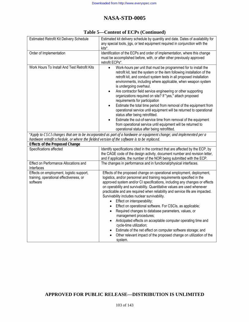
NASA-STD-0005
APPROVED FOR PUBLIC RELEASE—DISTRIBUTION IS UNLIMITED
103 of 143
Table 5—Content of ECPs (Continued)
Estimated Retrofit Kit Delivery Schedule Estimated kit delivery schedule by quantity and date. Dates of availability for any special tools, jigs, or test equipment required in conjunction with the kits*.
Order of Implementation Identification of the ECPs and order of implementation, where this change must be accomplished before, with, or after other previously approved retrofit ECPs*.
Work Hours To Install And Test Retrofit Kits • Work-hours per unit that must be programmed for to install the retrofit kit, test the system or the item following installation of the retrofit kit, and conduct system tests in all proposed installation environments, including where applicable, when weapon system is undergoing overhaul.
• Are contractor field service engineering or other supporting organizations required on site? If "yes," attach proposed requirements for participation
• Estimate the total time period from removal of the equipment from operational service until equipment will be returned to operational status after being retrofitted.
• Estimate the out-of-service time from removal of the equipment from operational service until equipment will be returned to operational status after being retrofitted.
*Apply to CSCI changes that are to be incorporated as part of a hardware or equipment change; and implemented per a hardware retrofit schedule, or where the fielded version of the software is to be replaced. Effects of the Proposed Change Specifications affected Identify specifications cited in the contract that are affected by the ECP, by
the CAGE code of the design activity, document number and revision letter, and if applicable, the number of the NOR being submitted with the ECP.
Effect on Performance Allocations and Interfaces
The changes in performance and in functional/physical interfaces.
Effects on employment, logistic support, training, operational effectiveness, or software
Effects of the proposed change on operational employment, deployment, logistics, and/or personnel and training requirements specified in the approved system and/or CI specifications, including any changes or effects on operability and survivability. Quantitative values are used whenever practicable and are required when reliability and service life are impacted. Survivability includes nuclear survivability.
• Effect on interoperability; • Effect on operational software. For CSCIs, as applicable; • Required changes to database parameters, values, or management procedures; • Anticipated effects on acceptable computer operating time and cycle-time utilization; • Estimate of the net effect on computer software storage; and • Other relevant impact of the proposed change on utilization of the system.
Downloaded from http://www.everyspec.com

NASA-STD-0005
APPROVED FOR PUBLIC RELEASE—DISTRIBUTION IS UNLIMITED
104 of 143
Table 5—Content of ECPs (Continued)
Effect On Acquisition Logistic Support Elements
The following will be covered, as applicable: • Effects on schedule and content of the ALS plan. • Effect on maintenance concept and plans for the levels of
maintenance and procedures. • System and/or CI logistics support analysis (LSA) tasks to be
accomplished and LSA data requiring update (MIL-PRF-49506) • Extension/revision of the interim support plan. • Spares and repair parts that are changed, modified, obsolete, or
added, including detailed supply data for interim support spares. • Revised or new technical manuals. • Revised or new facilities requirements and site activation plan. • New, revised, obsolete or additional support equipment (SE), test
procedures and software. • Description of the proposed change(s) to SE and trainers and
reference to related ECPs. • Effect on maintenance or training software. • Qualitative and quantitative personnel requirements data
identifying additions or deletions to operator or maintenance manpower requirements in terms of personnel skill levels, knowledge, and numbers required to support the modified CI.
• New operator and maintenance training requirements in terms of training equipment, trainers, and training software for operator and maintenance courses. This information should include identification of specific courses, equipment, technical manuals, personnel, etc., required to set up the course at either the contractor or government facility.
• Effect on contract maintenance that increases the scope or dollar limitation established in the contract.
• Effects on packaging, handling, storage, and transportability resulting from changes in materials, dimensions, fragility, inherent environmental or operating conditions.
Other considerations The effects of the proposed engineering change on the following will be
identified: • Interfaces having an effect on adjacent or related items (output,
input, size, mating connections, etc.). • GFE or Government Furnished Data (GFD) changed, modified, or
obsolete. • Physical constraints. Removal or repositioning of items, structural
rework, increase or decrease in overall dimensions. • Software (other than operational, maintenance, and training
software) requiring a change to existing code and/or resources, or addition of new software.
• Rework required on other equipment not included previously which will effect the existing operational configuration.
Downloaded from http://www.everyspec.com

NASA-STD-0005
APPROVED FOR PUBLIC RELEASE—DISTRIBUTION IS UNLIMITED
105 of 143
Table 5—Content of ECPs (Continued)
Other considerations (Continued) • Additional or modified system test procedures required. • Any new or additional changes having an effect on existing
warranties or guarantees. • Changes or updates to the parts control program. • Effects on life-cycle cost projections for the configuration item or
program, including projections of operation and support costs/savings for the item(s) affected over the contractually defined life and projections of the costs/savings to be realized in planned future production and spares buys of the item(s) affected.
Lower level items affected Identifier of lower level CI, CSCI, or parts affected, and the quantity and NSN of each part, where applicable.
Other systems/Configuration Items affected? Identify other systems affected by the proposed change that are outside the purview of the originator. Indicate whether the effect on other systems or CIs requires the submittal of related Class I ECPs.
Other activities affected? Identify other contractors or government activities that will be affected by this engineering change.
Effect On Product Configuration Documentation
If drawings or other product configuration documents that are ordered or provided by the Government are affected by the ECP, their identity by the CAGE code of the design activity, document number, revision letter, and, if applicable, the NOR number of the NOR being submitted with the ECP.
Estimated Net Total Cost Impact Production Costs/(Savings) Estimated costs/savings applicable to production of the item resulting from
the change. Includes the costs of redesign of the CIs or components thereof, of factory test equipment, of special factory tooling, of scrap, of engineering design, of engineering data revision, of revision of test procedures, and of testing and verification of performance of new items.
Retrofit Costs Estimated costs applicable to retrofit of the item including installation and testing costs. Includes retrofit-specific engineering data revision, prototype testing, kit proof testing, purchase of retrofit kits for operational systems, preparation of modification instructions, design and manufacture of special tooling for retrofit, installation of kits by contractor personnel, installation of kits by government personnel, testing after retrofit and modification, and testing and verification of performance of Government-Furnished Equipment/Property (GFE/GFP).
Logistics Support Costs/(Savings) Estimated costs/savings of the various elements of logistics support applicable to the item. Includes spares/repair parts rework (GFE/GFP), new spares and repair parts, supply/provisioning data,
Other Costs/Savings Includes estimated costs of interface changes accomplished by the Government for changes which must be accomplished in previously delivered items (aircraft, ships, facilities, etc.), other interfacing products, and/or retrofit of GFE/GFP, to the extent that such costs are not covered under production, retrofit, or logistics support.
Estimated Net Total Costs (Savings) Total of all the costs (savings) under contract and from other costs (savings).
Milestones ECP implementation milestones that show the time phasing of the various deliveries of items, support equipment, training equipment, and documentation incorporating the basic and related ECPs. Enter symbols and notations to show the initiation or termination of significant actions. Base all dates upon months after contractual approval of the basic ECPs.
Downloaded from http://www.everyspec.com

NASA-STD-0005
APPROVED FOR PUBLIC RELEASE—DISTRIBUTION IS UNLIMITED
106 of 143
D.5 Unrelated Engineering Changes
A separate ECP should be required for each engineering change which has its own distinct objective.
D.6 Revisions of Engineering Change Proposals (ECPs) An ECP should be revised when alterations or changes to the initial ECP are necessary. The first revision to an ECP should be identified by the entry of “R1” in the revision block of the ECP. Further revisions of the same ECP should be identified by the entry of “R2,” “R3,” etc. The date of the ECP should be the submission date of the revision.
a. Major revisions to an ECP should be made as a complete revised and resubmitted package.
b. Minor revisions to an ECP (such as those that correct errors, add or delete information, update pricing, or provide clarifications) may be made by attaching new or revised pages and indicate the new date and revision level on each newly revised page of the ECP. This will necessitate changing the page containing the date and revision level (blocks 1 and 8f), even if no other data on that sheet have changed.
c. In either case, the information which differs from the original ECP should be clearly identified in a manner similar to the marking of change pages for specifications. Block 19 of the ECP should include information on whether the revision is a resubmittal, replacing the existing ECP in its entirety, or provides change pages to the existing ECP.
D.7 Classified Data
When practicable, the ECP should be unclassified. Classified data essential to the evaluation and disposition of an ECP should be submitted separately in accordance with the approved security procedures and referenced in the unclassified portion of the ECP. The contractual DD Form 254, DoD Contract Security Classification Specification, applies.
D.8 Class I Engineering Change Proposals (ECPs)
Class I engineering changes should be limited to those which are necessary or offer significant benefit to the Government. Such changes are those required to:
a. Correct deficiencies.
b. Add or modify interface or interoperability requirements.
c. Make a significant and measurable effectiveness change in the operational capabilities or logistics supportability of the system or item.
d. Effect substantial life-cycle costs/savings, or
e. Prevent slippage in an approved production schedule.
Downloaded from http://www.everyspec.com

NASA-STD-0005
APPROVED FOR PUBLIC RELEASE—DISTRIBUTION IS UNLIMITED
107 of 143
D.9 Class I Engineering Change Package (ECP) Decisions
D.9.1 Engineering Change Package (ECP) Authorization
Unless otherwise specified by the Government, receipt of authorization constitutes the sole authority for the Supplier to effect a Class I change. Authorization of the change granted by the Government includes reference to the ECP by number, revision (if applicable), and date. Such authorization normally does not occur until the Government has performed a review for technical adequacy and supportability.
D.9.2 Class I Compatibility Engineering Changes
This category of change is intended to allow expeditious corrective action when the need for a change has been discovered during system or item functional checks or during installation and checkout. The Supplier should notify the Government by written message within 48 hours after determining that a compatibility change is necessary. The message should define the need for a compatibility change and identify factors that are impacted, including estimated costs and schedules. Unless otherwise prohibited by agreements, corrective action may then be implemented immediately by the Supplier to resolve such incompatibilities, but only for the specific item(s) situated in the location at which the deficiency was originally discovered. All aspects of the compatibility definition must apply. (See definition of Compatibility ECP in Appendix A.) In addition, a Class I compatibility ECP should be required within 30 days after initial notification. Where further action is necessary due to "lead time" considerations, the Supplier may initiate procurement or manufacturing action and should advise the Government with a change message referencing the serial number(s) and locations of additional items involved. The Supplier assumes total risk for implementation of such a change prior to Government authorization, except in those cases where the Government caused the incompatibility.
D.9.3 Disapproval of Engineering Change Packages (ECPs)
When the Government disapproves an ECP, the originator is notified in writing within 30 calendar days of the decision and is given the reason(s) for the disapproval.
D.9.4 Class I Engineering Change Package (ECP) Types
There are two types of Class I ECPs, preliminary and formal. The type of Class I ECP appropriate to the circumstances should be selected in accordance with the following definitions and guidelines.
D.9.4.1 Preliminary Change Proposal
A preliminary change proposal is the type submitted to the Government for review prior to the availability of the information necessary to support a formal ECP. The ECP should include a summary of the proposed change, its impact on related areas, and a justification.
Downloaded from http://www.everyspec.com

NASA-STD-0005
APPROVED FOR PUBLIC RELEASE—DISTRIBUTION IS UNLIMITED
108 of 143
D.9.4.2 Use of Preliminary ECPs (Type P)
A preliminary ECP may be prepared and submitted for one of the following purposes:
a. To furnish the Government with available information in order to permit:
(1) A preliminary evaluation relative to the merits of the proposed change (e.g., installation of a proposed change for the purpose of evaluation and testing prior to making a final decision to proceed with a proposed change); or
(2) A determination regarding the desirability of continuing expenditures required to
further develop the proposal.
b. To provide alternative proposals; or
c. To supplement a message relative to an emergency or urgent priority ECP when it is impracticable to submit a formal ECP within 30 calendar days; or
d. To propose a software change prior to the development of the actual coding changes and to obtain government approval to proceed with software engineering development.
D.9.5 Use of Advance Change Study Notice (ACSN)
Prior to the preparation of a formal Routine ECP, the Supplier and the Government should agree on the need for detailed information to be provided about the change idea involved. An ACSN, or a Supplier letter summarizing the change idea, should be used by either the Supplier or the Government to identify a topic for a change proposal. (Emergency, urgent, and compatibility type ECPs do not require an ACSN prior to submittal.) If the developer originates a change idea, the required information should be provided for government review. Upon receipt of a government-originated ACSN, the developer should evaluate the change idea (and any alternative courses of action identified by the Government). If authorized to do so by the agreements or the ACSN transmittal letter, and if in agreement with the change idea, the developer should proceed with preparation of the formal routine ECP. Otherwise, the agreement should provide additional information about the change to the Government for further study. In any case, the developer should not proceed with the preparation of the formal ECP until directed to do so by the Government. ACSNs should be prepared in developer format containing the information required by agreements.
D.9.6 Use of Formal Engineering Change Package (ECP) (Type F)
A formal ECP is the type that provides engineering information and other data in sufficient detail to support formal change approval/supplier implementation.
D.9.7 Class I Engineering Change Priorities
A priority should be assigned to each Class I ECP based upon the following definitions. The assigned priority determines the timeframe in which the ECP is to be reviewed, evaluated,
Downloaded from http://www.everyspec.com

NASA-STD-0005
APPROVED FOR PUBLIC RELEASE—DISTRIBUTION IS UNLIMITED
109 of 143
ordered, and implemented. The proposed priority is assigned by the originator and stands unless the Government has a valid reason for changing the priority.
a. Emergency. An emergency priority should be assigned to an engineering change proposed for either of the following reasons:
(1) To effect a change in operational characteristics which, if not accomplished without delay, may seriously compromise national security.
(2) To correct a hazardous condition that may result in fatal or serious injury to
personnel or in extensive damage or destruction of equipment. (A hazardous condition usually requires withdrawing the item from service temporarily, or suspension of the item operation, or discontinuance of further testing or development pending resolution of the condition.); or
(3) To correct a system halt (abnormal termination) in the production environment
such that CSCI mission accomplishment is prohibited.
b. Urgent. An urgent priority should be assigned to an engineering change proposed for any of the following reasons:
(1) To effect a change which, if not accomplished expeditiously, may seriously compromise the mission effectiveness of deployed equipment, software, or forces.
(2) To correct a potentially hazardous condition, the uncorrected existence of which
could result in injury to personnel or damage to equipment. (A potentially hazardous condition compromises safety and embodies risk, but within reasonable limits, permits continued use of the affected item provided the operator has been informed of the hazard and appropriate precautions have been defined and distributed to the user.)
(3) To meet significant Supplier requirements (e.g., when lead time will necessitate
slipping production or deployment schedules if the change was not incorporated). (4) To effect an interface change which, if delayed, would cause a schedule
slippage or increase cost. (5) To effect a significant net life-cycle cost savings to the Government, as defined in
the agreements, through value engineering or through other cost reduction efforts where expedited processing of the change will be a major factor in realizing lower costs.
(6) To correct unusable output critical to mission accomplishment. (7) To correct critical CI files that are being degraded.
Downloaded from http://www.everyspec.com

NASA-STD-0005
APPROVED FOR PUBLIC RELEASE—DISTRIBUTION IS UNLIMITED
110 of 143
(8) To effect a change in operational characteristics to implement a new or changed regulatory requirement with stringent completion date requirements issued by an authority higher than that of the functional proponent.
c. Routine. A routine priority should be assigned to a proposed engineering change when emergency or urgent is not applicable.
D.9.8 Expediting Class I Engineering Changes with Priority of Emergency or Urgent
ECPs carrying a priority of emergency and ECPs carrying a priority of urgent should be reported to the Government by telephone, message, personal contact, electronic transmission, or other expeditious means. All communications should be identified by the ECP number. If the initial communication regarding a proposed change was by other than written message, it should be confirmed by written message within 24 hours, and followed by a formal ECP within 30 days after the first communication unless otherwise specified by the Government. However, if it is impractical to complete a formal ECP within 30 days due to the necessity for extensive development, a preliminary ECP may be submitted within a 30-day period followed by a formal ECP at a specified interval thereafter. The preliminary or formal ECP should carry the same ECP number as the written message and should include reference to:
a. Method and date of the original communication.
b. Individuals contacted.
c. Source of resultant Supplier direction, if any.
D.9.9 Format for Class I Engineering Changes
Developer format is acceptable for proposing Class I engineering changes, as long as the ECP contents are presented in the block number sequence as presented in this appendix.
Downloaded from http://www.everyspec.com
NASA-STD-0005
APPROVED FOR PUBLIC RELEASE—DISTRIBUTION IS UNLIMITED
111 of 143
APPENDIX E GUIDELINES AND INSTRUCTIONS
FOR
FUNCTIONAL CONFIGURATION AUDITS (FCAs)
AND PHYSICAL CONFIGURATION AUDITS (PCAs)
E.1 Scope
This Appendix to the standard contains information intended for guidance/instructions for the performance of an FCA/PCA.
E.2 Supplier Participation and Responsibilities
The Supplier is responsible for supporting Government-conducted configuration audits in accordance with the following requirements except as amended by the agreements.
E.2.1 Sub-Suppliers and Suppliers
The Supplier is responsible for ensuring that Sub-Suppliers, vendors, and Suppliers participate in government configuration audits, as appropriate.
E.2.2 Location
Unless otherwise specified, the configuration audits should be conducted at the Supplier's facility. Accordingly, the Supplier should be required to provide the necessary resources and material to perform the audit effectively. This includes the following items to the extent appropriate for the type and scope of audit required by agreements:
a. Configuration audit plan. b. Conference agenda. c. Conference room(s). d. Applicable specifications, drawings, manuals, schedules, and design and test data. e. Test results. f. Meeting minutes including resulting audit action items. g. Tools and inspection equipment (including coordinate measuring machines with
operators) necessary for evaluation and verification. h. Unencumbered access to the areas and facilities of incoming inspection, fabrication,
production, and testing.
Downloaded from http://www.everyspec.com

NASA-STD-0005
APPROVED FOR PUBLIC RELEASE—DISTRIBUTION IS UNLIMITED
112 of 143
i. Personnel from each engineering, manufacturing, and quality department to be available for discussion in their respective areas.
j. Copies of inspection reports, process sheets, data sheets, and other documentation as
deemed necessary by government FCA/PCA teams. k. Isolation of the item(s) and detailed parts to be reviewed.
E.2.3 Supplier Requirements
The Supplier is responsible for establishing the time, place, and agenda for each configuration audit in consonance with the master milestone schedule, subject to coordination with the Government. This should be accomplished sufficiently in advance of each audit to allow adequate preparation for the meeting by both the Supplier and the Government. In addition, the Supplier is to:
a. Ensure that each configuration audit schedule is compatible with the availability of the necessary information and deliverables, e.g., system engineering data, trade study results, producibility analysis results, risk analysis results, specifications, manuals, drawings, reports, hardware, software, or mockups.
b. Designate a co-chairperson for each configuration audit. Participating Supplier and
Sub-Supplier personnel or those chosen to make presentations should be prepared to discuss in technical detail any of the presented material within the scope of the audit.
c. Provide an acceptable method to record inputs to official meeting minutes. Minutes
should be recorded and should consist of significant questions and answers, action items, waivers, conclusions, recommended courses of action resulting from presentations or discussions. Conclusions from discussions conducted during side meetings should be summarized in the main meeting at an appointed time, and appropriate comments should be read into the official minutes. Recommendations not accepted should also be recorded together with the reason for non-acceptance. The minutes of each daily session should be available for review by both the Supplier and Government personnel at the beginning of the next day's session. The minutes of the overall audit should be available for review by the Government prior to the departure of the audit team from the audit location. Official acknowledgment by the Government of the accomplishment of the audit should not be interpreted as approval of statements made in the minutes or of matters discussed at the audit and does not relieve the Supplier from requirements which are part of agreements.
d. Record all discrepancies identified by the audit team (see figure 3 for a sample Audit
Action Item List) and process each one, as a part of the audit activities, until it is closed out or suitable residual tasks, including identification of responsible activities and suspenses, have been established that lead to the closeout of the discrepancy/action item. Clearly record all action items in the minutes and identify both the Government and/or Supplier action required for each action item's resolution.
e. Publish the official minutes.
Downloaded from http://www.everyspec.com

NASA-STD-0005
APPROVED FOR PUBLIC RELEASE—DISTRIBUTION IS UNLIMITED
113 of 143
E.2.4 Government Participation
The Government:
a. Provides a co-chairperson. b. Provides to the Supplier prior to the audit the name, organization, and security
clearance of each participating individual. c. Reviews the daily minutes and ensures that they reflect all significant government
inputs. d. Provides formal acknowledgment to the Supplier of the accomplishment and results
of each configuration audit after receipt of configuration audit minutes. The Government evaluates the results of each configuration audit in accordance with the following identifiers:
(1) Approval - to indicate that the audit was satisfactorily completed. (2) Contingent approval - to indicate that the audit is not considered accomplished
until the satisfactory completion of resultant action items. (3) Disapproval - to indicate that the audit was seriously inadequate.
E.3 Functional Configuration Audit (FCA) A functional configuration audit is to be conducted for each configuration item for which a separate development or requirement specification has been baselined, except as otherwise required by agreements, and for the overall system, if required. The objective of the FCA is to verify the configuration item's and system's performance against its approved configuration documentation. Test data for the FCA should be that collected from the test of the configuration of the item that is to be formally accepted or released for production (prototype or preproduction article). If a prototype or preproduction article is not produced, the test data should be that collected from test of the first production article. Subject to prior government approval, the FCA for complex items may be conducted in increments. In such cases, a final FCA may be conducted to ensure that all requirements of the FCA have been satisfied. In cases where item verification can only be completely determined after system integration and testing, the (final) FCA should be conducted using the results of these tests.
Downloaded from http://www.everyspec.com

NASA-STD-0005
APPROVED FOR PUBLIC RELEASE—DISTRIBUTION IS UNLIMITED
114 of 143
Figure 3—Sample Audit Action Item List
AUDIT ACTION ITEM LIST - PART I PROBLEM IDENTIFICATION FCA PCA CONTROL NO. SUPPLIER CONTRACT NUMBER CAGE CODE ACTION ITEM ORIGINATOR ORGANIZATION NAME PHONE IDENTIFICATION OF ITEM BEING AUDITED CONFIGURATION ITEM NOMENCLATURE PART NUMBER SERIAL NUMBER SUB-ELEMENT AFFECTED CONTRACT REQUIREMENT(S) AFFECTED DOCUMENT PAGE PARAGRAPH NARRATIVE DESCRIPTION OF PROBLEM ALTERNATIVE APPROACH (OPTIONAL) FORWARDED BY: GROUP LDR TEAM LEADER
Downloaded from http://www.everyspec.com

NASA-STD-0005
APPROVED FOR PUBLIC RELEASE—DISTRIBUTION IS UNLIMITED
115 of 143
Figure 3—Sample Audit Action Item List (Continued)
E.3.1 Requirements
The schedule dates and actual accomplishment dates for the FCAs should be recorded in the CSA information system. The CI, or system, should not be audited separately without prior government approval of the Functional and Allocated Baselines for the CI, or system, involved. In addition, the Supplier should make the final draft copy of the CI product specification available to the Government for review prior to the FCA, as specified in agreements.
E.3.2 Supplier Responsibility
a. Prior to the audit date, the Supplier should provide the following information to the Government:
AUDIT ACTION ITEM LIST PART II PROBLEM RESOLUTION FCA PCA CONTROL NO. SUPPLIER'S RESPONSE OPEN (Follow-up action required) CLOSED (No follow-up required) FIRST ACTION ASSIGNED TO SUSPENSE SECOND ACTION ASSIGNED TO SUSPENSE CONCURRENCE SIGNATURES SUPPLIER GOVERNMENT RESOLUTION GOVERNMENT ACTION ITEM CLOSEOUT ORIGINATOR AUDIT TEAM NAME SIGNATURE DATE GOVERNMENT SUPPLIER
Downloaded from http://www.everyspec.com

NASA-STD-0005
APPROVED FOR PUBLIC RELEASE—DISTRIBUTION IS UNLIMITED
116 of 143
(l) Supplier representation. (2) Identification of items to be audited.
A. Nomenclature. B. Specification identification number. C. CI identification.
(3) Current listing of all deviations/waivers against the CI, either requested of or
approved by the Government. (4) Status of test programs to test configuration items with automatic test equipment
(when applicable).
b. The Supplier should provide a matrix for each CI at the FCA that identifies the requirements of sections 3 and 4 of the specifications; includes a cross reference to the test plan, test procedures, and test report, results of demonstrations, inspections, and analyses for each requirement; and identifies each deficiency by deficiency report number. The matrix should be made a part of the FCA minutes.
c. The Supplier should prepare an FCA check sheet which identifies documents to be
audited and tasks to be accomplished at the FCA for the CI. A sample FCA checklist is shown in figure 4. E.3.3 Verification Procedures and Requirements The Supplier should provide the FCA team with a briefing for each CI being audited and should delineate the test results and findings for each CI. As a minimum, the discussion should include CI requirements that were not met, including a proposed solution to each item, an account of the ECPs incorporated and tested as well as proposed, and general presentation of the entire CI test effort delineating problem areas as well as accomplishments. The audit should also include the following:
a. The Supplier's test procedures and results should be reviewed for compliance with specification requirements.
b. The following testing information should be available for the FCA team:
(l) Test plans, specifications, descriptions, procedures, and reports for the CI. (2) A complete list of successfully accomplished tests during which pre-acceptance
data were recorded. (3) A complete list of successful tests if detailed test data are not recorded.
Downloaded from http://www.everyspec.com

NASA-STD-0005
APPROVED FOR PUBLIC RELEASE—DISTRIBUTION IS UNLIMITED
117 of 143
(4) A complete list of tests required by the test requirements but not yet performed.
(To be performed as a system or subsystem test). (5) Preproduction test results.
c. An audit of formal test plans, specifications, and procedures should be made and
compared against the official test data. The results should be checked for completeness and accuracy. Deficiencies should be documented and made part of the FCA minutes. Interface requirements and the testing of these requirements should be reviewed. Completion dates for all discrepancies should be clearly established and documented.
d. For those requirements which cannot be completely verified through the use of
testing, the FCA should determine whether adequate analyses or simulations have been accomplished and whether the results of the analyses or simulations are sufficient to ensure that the CI meets the requirements in the specification. All ECPs that have been approved should be reviewed to ensure that they have been technically incorporated and verified.
e. An audit of the test reports should be performed to validate that the reports are
accurate and completely describe the CI tests. Test reports, procedures, and data used by the FCA team should be made a matter of record in the FCA minutes.
f. A list of the Supplier's internal configuration documentation of the HWCI should be
reviewed to ensure that the Supplier has documented the physical configuration of the HWCI for which the test data are verified.
g. Drawings of the CI parts which are to be provisioned should be selectively sampled to
ensure that test data essential to manufacturing are included on, or furnished with, the drawings. h. CIs which fail to pass quality requirements are to be analyzed as to the cause of
failure to pass. Appropriate corrections should be made before a CI is subjected to a re-verification.
i. Acknowledge accomplishment of partial completion of the FCA for those CIs whose
verification is contingent upon completion of integrated system testing.
Downloaded from http://www.everyspec.com

NASA-STD-0005
APPROVED FOR PUBLIC RELEASE—DISTRIBUTION IS UNLIMITED
118 of 143
Figure 4—Sample Functional Configuration Audit (FCA) Checklist
j. For CSCIs the following additional requirements apply:
(1) Review database characteristics, storage allocation data and timing, and
sequencing characteristics for compliance with specified requirements. (2) Review all documents that compose or describe the contents or the use of the
software product for format and completeness (e.g., software product specification, User's Manual, VDD).
(3) Review the records that reflect changes made to the developmental configuration
for the CSCI. (4) Review the listing of all versions of the developmental and non-developmental
software for the CSCIs that are in the software library. (5) Review the findings of all internal CM and Software Quality Assurance audits of
the CSCI.
FCA CHECKLIST NOMENCLATURE CI IDENTIFIER DATE SUPPLIER REQUIREMENTS YES NO 1. Waiver/Deviation List Prepared. 2. Verification Test Procedures Submitted. 3. Verification Testing Completed. 4. Verification Test Results Compiled and Available. 5. Facilities for Conducting FCA Available. 6. Verification Test Procedures Reviewed and Approved. 7. Verification Testing Witnessed. 8. Verification Test Data and Results Reviewed and Approved. COMMENTS
Downloaded from http://www.everyspec.com

NASA-STD-0005
APPROVED FOR PUBLIC RELEASE—DISTRIBUTION IS UNLIMITED
119 of 143
k. Preliminary and CDR minutes should be examined to ensure that all findings have
been incorporated and completed
E.3.4 Post-Audit Actions
After the FCA is completed, the Supplier should:
a. Publish copies of the FCA minutes.
b. Record the accomplishments and results of the FCA in the CSA record for each CI audited.
c. Accomplish residual tasks for which they were identified as the responsible activity.
E.3.5 Functional Configuration Audit Certifications A sample FCA certification package is shown in Figure 5. When specified, a Configuration Audit Summary Report consisting of the applicable information of the certification package is required.
Figure 5—Sample Functional Configuration Audit (FCA) Certification Package
FCA CERTIFICATION PACKAGE FOR CI IDENTIFIER(s) CONTRACT NO. PRIME SUPPLIER: EQUIPMENT MANUFACTURERS: APPROVED BY APPROVED BY (SUPPLIER) (GOVERNMENT)
Downloaded from http://www.everyspec.com

NASA-STD-0005
APPROVED FOR PUBLIC RELEASE—DISTRIBUTION IS UNLIMITED
120 of 143
Figure 5—Sample FCA Certification Package (Continued)
SCOPE/PURPOSE SCOPE: Functional Configuration Audit (FCA) was conducted on the following Configuration Item: CI Identifier Nomenclature Part No. Serial No. PURPOSE: The purpose of this FCA was to verify that the configuration item's performance complied with the Development Specification.
Downloaded from http://www.everyspec.com

NASA-STD-0005
APPROVED FOR PUBLIC RELEASE—DISTRIBUTION IS UNLIMITED
121 of 143
FCA CERTIFICATION SHEET NO. 1 (For Equipment/Computer S/W) Contract: Date: Supplier: CI Identifier: Verification Test Procedures and Results. The team shall affirm the following: The verification test/analysis results have been reviewed to ensure that testing is adequate, properly done, and certified. (All test procedures and interface documents should be reviewed to assure that the documents have been approved by the Government.) All test data sheets should be reviewed to assure that the test was witnessed by a representative of the Government. Attached is a list of the documents reviewed Check One O Procedures and results reviewed satisfy the requirements and are accepted (see attachment for comments). O Attached is a list of deficiencies. * Signature(s) of FCA Team Member(s) * Sub-Team Chairperson
Figure 5—Sample FCA Certification Package (Continued)
Downloaded from http://www.everyspec.com

NASA-STD-0005
APPROVED FOR PUBLIC RELEASE—DISTRIBUTION IS UNLIMITED
122 of 143
FCA CERTIFICATION SHEET NO. 2 (For Equipment/Computer S/W) Contract: Date: Supplier: CI Identifier: Review of Deviations/Waivers. The Team shall affirm the following: A review of all deviations/waivers to military specifications and standards that have been approved. The purpose is to determine the extent to which the equipment (CI/computer S/W) undergoing FCA varies from the released specifications and to form a basis for satisfactory compliance with these specifications and standards. In accordance with this paragraph, all applicable deviations/waivers have been reviewed with the following results: Check One The equipment(s)/computer S/W listed on Certification Sheet No. 1 of this report complies with all applicable specifications and standards. See attachment __ for comments. O Attached is a summary of FCA discrepancies. O Signature(s) of FCA Team Member(s) * * Sub-Team Chairperson A. Deviation/Waiver Review Team Instructions. All approved waivers and deviations to military specifications and standards should be reviewed and recorded. Also, record any part of the FCA which fails to meet specifications or standards but is not an approved waiver/deviation. B. Results of Team Review. List the deviations/waivers that were reviewed against the equipment/computer S/W undergoing an FCA.
Figure 5—Sample FCA Certification Package (Continued)
Downloaded from http://www.everyspec.com

NASA-STD-0005
APPROVED FOR PUBLIC RELEASE—DISTRIBUTION IS UNLIMITED
123 of 143
E.4 Physical Configuration Audit (PCA) The PCA is the formal examination of the as-built configuration of a CI against its design documentation. The PCA for a CI should not be started unless the FCA for the CI has already been accomplished or is being accomplished concurrent with the PCA. After successful completion of the audit and the establishment of a Product Baseline, all subsequent changes are processed by formal engineering change action. The PCA also determines that the acceptance testing requirements prescribed by the documentation is adequate for acceptance of production units of a CI by quality assurance activities. The PCA includes a detailed audit of engineering drawings, specifications, technical data, tests utilized in production of CIs, and design documentation, listings, and operation and support documents for CSCIs. The PCA should include an audit of the released engineering documentation and quality control records to make sure the as-built or as-coded configuration is reflected by this documentation. For software, the product specification, Interface Design Document, and VDD should be a part of the PCA.
a. The PCA should be conducted on a unit of the item selected jointly by the Government and the Supplier.
b. Satisfactory completion of a PCA and approval of the product specification are
necessary for the Government to establish the Product Baseline for a CI.
E.4.1 Requirements
The schedule dates, and actual accomplishment dates, for the PCAs should be recorded in the CSA information system. All engineering changes approved internally, and those approved by the Government should be incorporated into new revisions of the applicable configuration documentation prior to the PCA. In addition, the Supplier should make the final draft copy of the product specification available to the Government for review prior to the PCA, as specified in agreements.
E.4.2 Supplier Responsibility
Prior to the audit date, the Supplier should provide the following information to the Government. A sample PCA Checklist is shown in Figure 6.
a. Supplier representation.
b. Identification of items to be audited by:
(1) Nomenclature. (2) Specification Identification Number. (3) CI Identifiers. (4) Serial numbers.
Downloaded from http://www.everyspec.com

NASA-STD-0005
APPROVED FOR PUBLIC RELEASE—DISTRIBUTION IS UNLIMITED
124 of 143
(5) Drawing and part numbers. (6) CAGE Codes.
c. A list delineating all deviations/waivers against the CI either requested or government
approved. d. Reference information to the CI being audited as follows:
(1) CI product specification. (2) A list delineating both approved and outstanding changes against the CI. (3) Complete shortage list. (4) Acceptance test procedures and associated test data. (5) Engineering drawing index including revision letters. (6) Operation and support manuals; including operator manuals, maintenance
manuals, illustrated parts breakdown, programmer's manuals, diagnostic manuals, etc.
(7) Proposed DD Form 250, “Material Inspection and Receiving Report.” (8) Approved nomenclature and nameplates. (9) VDDs for software. (10) FCA minutes for each CI. (11) Findings/Status of Quality Assurance Programs. (12) Program parts selection list. (13) Interface Design Document for software.
e. At time of audit, assemble and make available to the PCA team all data describing the
item configuration, to include:
(1) Current approved issue of hardware development and software and interface requirements specifications to include approved SCNs and approved deviations/waivers.
(2) Identification of all changes actually made during test.
Downloaded from http://www.everyspec.com

NASA-STD-0005
APPROVED FOR PUBLIC RELEASE—DISTRIBUTION IS UNLIMITED
125 of 143
(3) Identification of all required changes not completed. (4) All configuration documentation, or electronic representations of the same,
required to identify the CI. (5) Manufacturing instructions, manufacturing instruction sheets, or CAM data
related to drawings and computer-aided design presentations of specified parts identified by the Government.
f. Identify any difference between the physical configurations of the selected production
unit and the development unit(s) used for the FCA and to certify or demonstrate to the Government that these differences do not degrade the functional characteristics of the selected units.
E.4.3 Physical Configuration Audit (PCA) Procedures and Requirements
The following actions should be performed as part of each PCA:
A representative number of drawings (and/or CAD presentations) and associated manufacturing instruction sheets (and/or CAM data) for each item of hardware, identified by the Government co-chairperson, should be reviewed to determine their accuracy and ensure that they include the authorized changes reflected in the engineering drawings (and/or CAD presentations) and the hardware. Unless otherwise directed by the Government co-chairperson, inspection of drawings (and/or CAD presentations) and associated manufacturing instructions (and/or CAM data) may be accomplished on a valid sampling basis. The purpose of this review is to ensure that the manufacturing instructions (and/or CAM data) accurately reflect all design details contained in the drawings (and/or CAD presentations). Since the hardware is built in accordance with the manufacturing instructions (and/or CAM data), any discrepancies between the manufacturing instructions (and/or CAM data) and the design details and changes in the drawings (and/or CAD presentations) will be reflected in the hardware.
Downloaded from http://www.everyspec.com

NASA-STD-0005
APPROVED FOR PUBLIC RELEASE—DISTRIBUTION IS UNLIMITED
126 of 143
Figure 6—Sample PCA Checklist
PCA CHECKLIST The following hardware (H/W) and computer software (S/W) documentation should be available, and the following tasks are to be accomplished at the PCA. Hardware: Computer S/W: Documentation: (1) Approved final draft of the configuration item product specification.
(2) A list delineating both approved and outstanding changes against the configuration item.
(3) Complete shortage list.
(4) Acceptance test procedures and associated test data.
(5) Engineering Drawing Index.
(6) Operating, maintenance, and illustrated parts breakdown manuals.
(7) List of approved material review board actions on waivers.
(8) Proposed DD Form 250, "Material Inspection and Receiving Report."
(9) Approved nomenclature and nameplates.
(10) Manuscript copy of all S/W Cl manuals.
(11) Computer S/W VDD.
(12) Current set of listings and updated design descriptions or other means of design portrayal for each S/W Cl.
(13) FCA minutes for each configuration item.
(14) NASA Parts Selection List.
Note: The NASA Parts Selection provides a viable alternative for parts selection since the cancellation of MIL-STD-975, even though it is not intended to be invoked as a contract requirement. Basically, the NASA Parts Selection List is to be used as a tool to augment their own existing part selection lists. Tasks: (I) Define Product Baseline.
(2) Review and validate specifications.
(3) Review drawings.
(4) Review acceptance test procedures and results.
(5) Review shortages and unincorporated design changes.
(6) Review deviations/waivers.
(7) Examine proposed DD 250.
(8) Review performing activity's release and Change Control System.
Figure 6—Sample Physical Configuration Audit (PCA) Checklist
Downloaded from http://www.everyspec.com
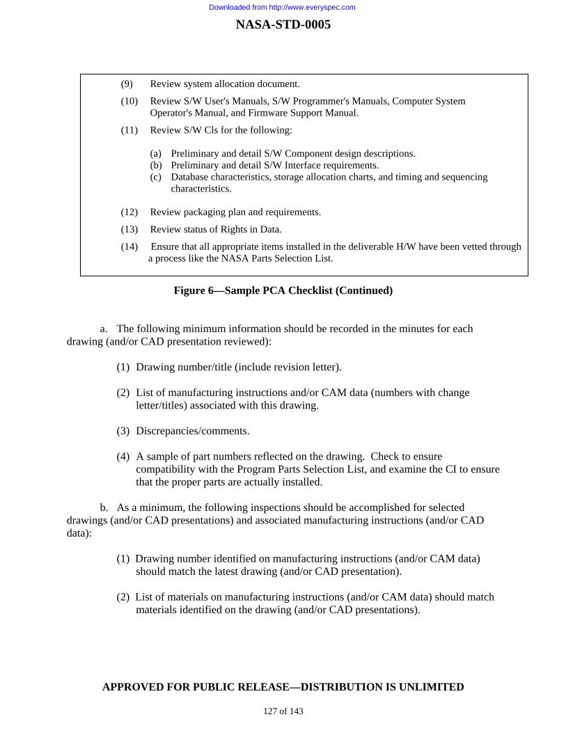
NASA-STD-0005
APPROVED FOR PUBLIC RELEASE—DISTRIBUTION IS UNLIMITED
127 of 143
Figure 6—Sample PCA Checklist (Continued)
a. The following minimum information should be recorded in the minutes for each drawing (and/or CAD presentation reviewed):
(1) Drawing number/title (include revision letter). (2) List of manufacturing instructions and/or CAM data (numbers with change
letter/titles) associated with this drawing. (3) Discrepancies/comments. (4) A sample of part numbers reflected on the drawing. Check to ensure
compatibility with the Program Parts Selection List, and examine the CI to ensure that the proper parts are actually installed.
b. As a minimum, the following inspections should be accomplished for selected
drawings (and/or CAD presentations) and associated manufacturing instructions (and/or CAD data):
(1) Drawing number identified on manufacturing instructions (and/or CAM data) should match the latest drawing (and/or CAD presentation).
(2) List of materials on manufacturing instructions (and/or CAM data) should match
materials identified on the drawing (and/or CAD presentations).
(9) Review system allocation document.
(10) Review S/W User's Manuals, S/W Programmer's Manuals, Computer System Operator's Manual, and Firmware Support Manual.
(11) Review S/W Cls for the following: (a) Preliminary and detail S/W Component design descriptions. (b) Preliminary and detail S/W Interface requirements. (c) Database characteristics, storage allocation charts, and timing and sequencing characteristics. (12) Review packaging plan and requirements.
(13) Review status of Rights in Data.
(14) Ensure that all appropriate items installed in the deliverable H/W have been vetted through a process like the NASA Parts Selection List.
Downloaded from http://www.everyspec.com

NASA-STD-0005
APPROVED FOR PUBLIC RELEASE—DISTRIBUTION IS UNLIMITED
128 of 143
(3) Nomenclature descriptions, part numbers, and serial number markings called out on the drawing (and/or CAD presentation) should be identified on the manufacturing instructions (and/or CAM data).
(4) Drawings (and/or CAD presentations) and associated manufacturing instructions
(and/or CAM data) should be reviewed to ascertain that all approved changes have been incorporated into the CI.
(5) Release records should be checked to ensure all drawings (and/or CAD
presentations) reviewed are identified. (6) The number of any drawings (and/or CAD presentations) containing more than
five outstanding changes attached to the drawing should be recorded. (7) The drawings (and/or CAD presentations) of a major assembly/black box of the
HWCI should be checked for continuity from top drawing down to piece-part drawing.
(8) Ensure that approvals by the Government are present where required.
c. Compare the Program Parts Selection List (PPSL) to the HWCI/engineering drawing
package to ensure only approved parts are listed. d. Review of all records of baseline configuration for the CI by direct comparison with
the Supplier's Engineering Release System and change control procedures to verify that the configuration being produced accurately reflects released engineering data. This includes interim releases of spares/repair parts provisioned prior to PCA to ensure delivery of currently configured spares/repair parts.
e. Audit the software library or similar internal support activity to ensure that it
accurately identifies, controls, and tracks changes to the software and documentation. Audit the Supplier's engineering release and change control system against the requirements in NASA-STD-0005 to ascertain that the system is adequate to properly control the processing and formal release of engineering changes. The Supplier's system should meet the information and capabilities requirements of NASA-STD-0005 as a minimum. The Supplier's formats, systems, and procedures may be used.
f. CI acceptance test data and procedures should comply with product specifications.
The PCA team should determine any acceptance tests to be accomplished again and reserves the right to have representatives of the Government witness all or any portion of the required audits, inspections, or tests.
g. CIs which fail to pass acceptance testing should be repaired if necessary and should
be retested by the Supplier either in the manner specified by the PCA team leader or in accordance with procedures in the product specification.
Downloaded from http://www.everyspec.com

NASA-STD-0005
APPROVED FOR PUBLIC RELEASE—DISTRIBUTION IS UNLIMITED
129 of 143
h. Present data confirming the inspection and test of Sub-Supplier equipment end items at point of manufacture. Inspection and tests should have been witnessed by a government representative.
i. The PCA team should review the prepared backup data (all initial documentation
which accompanies the CI) for correct types and quantities to ensure adequate coverage at the time of shipment to the user.
j. CIs that have demonstrated compliance with the product specification will be
approved for acceptance. The PCA team should certify by signature that the CI has been built in accordance with the drawings and specifications.
k. As a minimum, the following actions should be performed by the PCA team on each
CSCI being audited:
(1) Review all documents that comprise the product specification for format and completeness.
(2) Review FCA minutes for recorded discrepancies and actions taken. (3) Review the design descriptions for proper entries, symbols, labels, tags,
references, and data descriptions. (4) Compare detailed design descriptions with the software listings for accuracy and
completeness. (5) Examine actual CSCI delivery media (discs, tape, etc.) to ensure conformance
with section 5 of the software requirements specifications. (6) Review the annotated listings for compliance with approved coding standards. (7) Review all required operation and support documentation for completeness,
correctness, incorporation of comments made at Test Readiness Review, and adequacy to operate and support the CSCIs. (Formal verification or acceptance of these manuals should be withheld until system testing to ensure that the procedural contents are correct.).
(8) Examine the related documentation to ensure that the relationship of the CSCI to
the parts, components, or assemblies that store the executable forms of the CSCI is properly described. For firmware, ensure that the information completely describes the requirements for installation of the CSCI into the programmable part or assemblies and that this information describes the requirements for verification that the installation has been properly implemented. Where follow-on acquisition of the firmware items is intended, ensure that the documentation has been accomplished to the level of detail necessary for the intended re-procurement.
Downloaded from http://www.everyspec.com

NASA-STD-0005
APPROVED FOR PUBLIC RELEASE—DISTRIBUTION IS UNLIMITED
130 of 143
(9) Demonstrate, using deliverable or government-owned support S/W, that each
CSCI can be regenerated. The regenerated CSCI should be compared to the actual CSCI delivery media to ensure they are identical.
E.4.4 Post-Audit Actions
a. The Government will notify the Supplier in writing by the Government of acceptance or rejection of the PCA, of PCA status and discrepancies to be corrected, or rejection of the PCA and requirements for re-accomplishment.
b. After completion of the PCA, the Supplier should publish and distribute copies of
PCA minutes as specified in agreements. The results of the PPSL review are included in the final PCA minutes.
c. Accomplish residual tasks that were identified as the responsible activity.
E.4.5 Physical Configuration Audit Certification A sample PCA certification package is shown in Figure 7. When specified, a Configuration Audit Summary Report, consisting of the applicable information of the certification package, is required.
Figure 7—Sample Physical Configuration Audit (PCA) Certification Package
PCA CERTIFICATION PACKAGE CI IDENTIFIER: CONTRACT NO. PRIME SUPPLIER: EQUIPMENT MANUFACTURERS: APPROVED BY (Designee) APPROVED BY (Designee) (SUPPLIER) (GOVERNMENT) DATE DATE
Downloaded from http://www.everyspec.com

NASA-STD-0005
APPROVED FOR PUBLIC RELEASE—DISTRIBUTION IS UNLIMITED
131 of 143
Figure 7—Sample PCA Certification Package (Continued)
SCOPE/PURPOSE Scope: A Physical Configuration Audit (PCA) was conducted on the following end items of equipment/computer S/W: CI IDENTIFIER CI NOMENCLATURE PART NUMBER SERIAL NO. NSN Purpose. The purpose of the PCA was to ensure accuracy of the identifying documentation and to establish a product baseline. The establishment of a product baseline for equipment/computer S/W is not to be construed as meeting Government requirements for delivery of an operational system meeting approved acceptance criteria. Definition of Terms Comment - A note explaining, illustrating, or criticizing the meaning of written material. Items of this nature should be explored by the Supplier and/or the Government, but corrective action is NOT necessary to successfully accomplish the PCA. Discrepancy - A note explaining, illustrating, or criticizing the difference between writings. A note showing the variance between what exists and what is acceptable. Items of this nature should be rectified by the Supplier prior to successful accomplishment of a PCA.
Downloaded from http://www.everyspec.com

NASA-STD-0005
APPROVED FOR PUBLIC RELEASE—DISTRIBUTION IS UNLIMITED
132 of 143
Figure 7—Sample PCA Certification Package (Continued)
PCA CERTIFICATION SHEET NO. 1 (For Equipment/Computer S/W) Contract: Date: Supplier: Product Baseline. The following documents of the issue and date shown compose the product baseline for the listed equipment(s)/computer S/W: ASSEMBLY TOP EQUIPMENT/COMPUTER SPEC NO. DRAWING NO. ISSUE S/W NOMENCLATURE Signature(s) of PCA Team Member(s) ** * ** Team Chairperson * Sub-Team Chairperson
Downloaded from http://www.everyspec.com

NASA-STD-0005
APPROVED FOR PUBLIC RELEASE—DISTRIBUTION IS UNLIMITED
133 of 143
Figure 7—Sample PCA Certification Package (Continued)
PCA CERTIFICATION SHEET NO. 2 (For Equipment/Computer S/W)
Contract: Date:
Supplier:
Specification Review and Validation. Specifications have been reviewed and validated to ensure that they adequately define the configuration item and the necessary testing, mobility/transportability and packaging requirements.
Check One
O The Product Specifications are complete and adequately define the configuration item. They should, therefore, constitute the product baseline. See attachment __ for comments.
O The Product Specifications are unacceptable. See attachment __ for a list of discrepancies.
Signature(s) of PCA Team Member(s) ** * ** Team Chairperson * Sub-Team Chairperson
A. Specification Review and Validation Instruction. The detailed specifications listed in paragraph B below should be reviewed for compliance with the applicable requirements. Each specification should serve as the basic document for configuration control of the subject configuration items. The information contained within the specifications should be audited at the PCA.
B. Review and Validation Results
1. Specifications reviewed and validated:
EQUIPMENT/COMPUTER SPEC NO PART NO DATE S/W NOMENCLATURE
2. Specifications reviewed and disapproved: EQUIPMENT/COMPUTER SPEC NO PART NO DATE S/W NOMENCLATURE
Downloaded from http://www.everyspec.com

NASA-STD-0005
APPROVED FOR PUBLIC RELEASE—DISTRIBUTION IS UNLIMITED
134 of 143
Figure 7—Sample PCA Certification Package (Continued)
PCA CERTIFICATION SHEET NO. 3 (Equipment) Contract: Date: Supplier: Drawing Review. Drawings have been compared with the equipment to ensure that the latest drawing change letter has been incorporated into the equipment, that part numbers agree with the drawings, and that the drawings are complete and accurately describe the equipment. Check One O The drawings are complete and accurately describe the equipment. See attachment _ for comments. O The drawings are compatible with the applicable contract PPSL. Attachment __ is a list of discrepancies. Signature(s) of PCA Team Member(s) * * Sub-Team Chairperson A. Drawing Review Results. The following drawings were reviewed by the PCA drawing review sub-team: DOCUMENT NUMBER DOCUMENT TITLE
Downloaded from http://www.everyspec.com

NASA-STD-0005
APPROVED FOR PUBLIC RELEASE—DISTRIBUTION IS UNLIMITED
135 of 143
Figure 7—Sample PCA Certification Package (Continued)
PCA CERTIFICATION SHEET NO. 4 (Equipment) Contract: Date: Supplier Acceptance Test Procedures and Results. The acceptance test procedures have been reviewed for adequacy and the acceptance test results have been reviewed to ensure that the testing has been properly done and certified. Attachment __ is a list of the documents reviewed. Check One O Procedures and results reviewed satisfy the requirements and are accepted. See attachment __ for comments. O Attachment is a list of discrepancies. Signature(s) of PCA Team Member(s) * Sub-Team Chairperson A. Government Acceptance Test Procedures. The following acceptance test procedures were reviewed by the ATP Sub-Team: DOCUMENT NUMBER DATE/REV LTR DOCUMENT STATUS B. Government Acceptance Test Results. The following acceptance test results documentation was reviewed by the ATR Sub-Team: DOCUMENT NUMBER DATE/REV LTR DOCUMENT STATUS
Downloaded from http://www.everyspec.com
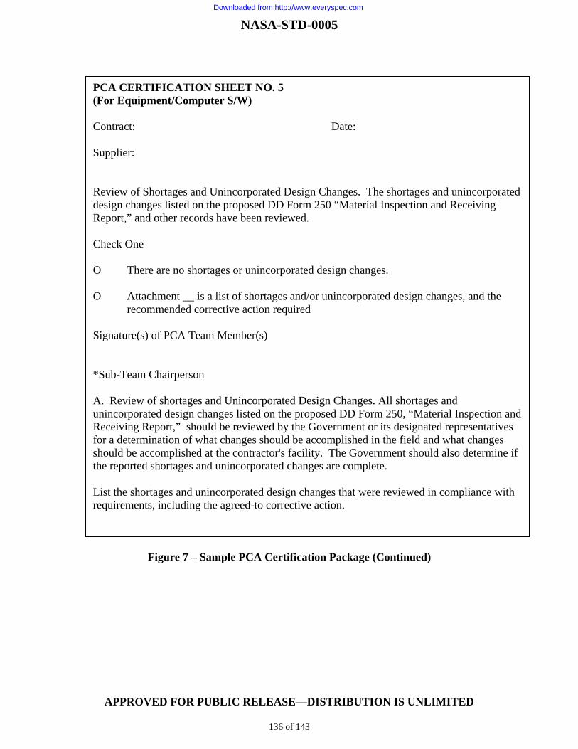
NASA-STD-0005
APPROVED FOR PUBLIC RELEASE—DISTRIBUTION IS UNLIMITED
136 of 143
Figure 7 – Sample PCA Certification Package (Continued)
PCA CERTIFICATION SHEET NO. 5 (For Equipment/Computer S/W) Contract: Date: Supplier: Review of Shortages and Unincorporated Design Changes. The shortages and unincorporated design changes listed on the proposed DD Form 250 “Material Inspection and Receiving Report,” and other records have been reviewed. Check One O There are no shortages or unincorporated design changes. O Attachment __ is a list of shortages and/or unincorporated design changes, and the recommended corrective action required Signature(s) of PCA Team Member(s) *Sub-Team Chairperson A. Review of shortages and Unincorporated Design Changes. All shortages and unincorporated design changes listed on the proposed DD Form 250, “Material Inspection and Receiving Report,” should be reviewed by the Government or its designated representatives for a determination of what changes should be accomplished in the field and what changes should be accomplished at the contractor's facility. The Government should also determine if the reported shortages and unincorporated changes are complete. List the shortages and unincorporated design changes that were reviewed in compliance with requirements, including the agreed-to corrective action.
Downloaded from http://www.everyspec.com

NASA-STD-0005
APPROVED FOR PUBLIC RELEASE—DISTRIBUTION IS UNLIMITED
137 of 143
Figure 7 – Sample PCA Certification Package (Continued)
PCA CERTIFICATION SHEET NO. 6 (For Equipment/Computer S/W) Contract: Date: Supplier: Review Waivers/Deviations: A review of all deviations/waivers to military specifications and standards that have been approved. The purpose is to determine the extent to which the equipment(s)/computer S/W undergoing PCA varies from applicable specifications and standards and to form a basis for satisfactory compliance with these specifications and standards. The equipment(s)/computer S/W listed on Certification Sheet No. 1 of this report complies with all applicable specifications and standards. See attachment ___ for comments. Attachment _ is a list of discrepancies and/or comments. In accordance with this paragraph, all applicable deviations/waivers have been reviewed with the following results: Signature(s) of PCA Team Member(s) Deviation/Waiver; Review Team Instructions. All approved waivers and deviations to military specifications and standards should be reviewed and recorded. Also, record any part of the PCA which fails to meet specifications or standards but is not an approved waiver/deviation. Results of Team Review. List the deviations/waivers against the equipment/computer S/W undergoing a PCA that was reviewed
Downloaded from http://www.everyspec.com

NASA-STD-0005
APPROVED FOR PUBLIC RELEASE—DISTRIBUTION IS UNLIMITED
138 of 143
Figure 7 – Sample PCA Certification Package (Continued)
PCA CERTIFICATION SHEET NO. 7 (For Equipment/Computer S/W) Contract: Date: Supplier: Examination of the Proposed DD Form 250. The DD Form 250 has been examined to ensure that it adequately defines the equipment/computer S/W and that unaccomplished tasks are included as deficiencies. Check One O The DD Form 250 adequately defines the equipment/computer S/W and all unaccomplished tasks are included as deficiencies. O Attachment __ is a list of discrepancies and/or comments. * Sub-Team Chairperson A. Examination of Proposed DD Form 250. The proposed DD Form 250 should be examined for completeness and for an accurate definition of the equipment/computer S/W. Unaccomplished tasks, shortages, and certain specified discrepancies uncorrected at the PCA should be included in the DD Form 250. If the equipment/computer S/W is to be shipped from the plant, the Program Office Representative shall recommend to the Contract Administrative Office that the DD Form 250 be executed in accordance with the terms of the contract. B. Results. Include a statement that the proposed DD Form 250 was examined and recommended.
Downloaded from http://www.everyspec.com

NASA-STD-0005
APPROVED FOR PUBLIC RELEASE—DISTRIBUTION IS UNLIMITED
139 of 143
Figure 7 – Sample PCA Certification Package (Continued)
PCA CERTIFICATION SHEET NO. 8 (For Equipment/Computer S/W) Contract: Date: Supplier: Review of Supplier’s Engineering; Release and Change Control System. The contractor's engineering release system and change control procedures have been reviewed to ensure that they are adequate to properly control the processing and formal release of engineering changes. Check One O The Supplier's engineering release system and change control procedures are adequate for processing and formal release of engineering changes. See attachment for comments. O Attachment __ is a list of deficiencies. Signature(s) of PCA Team Member(s) Sub-Team Chairperson
Downloaded from http://www.everyspec.com

NASA-STD-0005
APPROVED FOR PUBLIC RELEASE—DISTRIBUTION IS UNLIMITED
140 of 143
Figure 7 – Sample PCA Certification Package (Continued)
PCA CERTIFICATION SHEET NO. 9 (Equipment) Contract: Date: Supplier 1. Review of Logistics Support Plan for Pre-operational Support. The Logistics Support Plan for Pre-operational Support has been reviewed to ensure that it is adequate to support the acquisition phase and that it is compatible with the operational phase maintenance concept and support requirements. Check One O The Supplier's Logistic Plan for pre-operational support shall fulfill the acquisition phase requirements and is compatible with operational phase needs. O Attachment __ is a list of deficiencies. 2. Review of Long Lead-Time Items and Provisioned Items Processed prior to PCA. Long lead-time items released and items provisioned prior to PCA have been reviewed to ensure that obsolete items resulting from pre-PCA design changes are purged from the system. Where basic items may be upgraded by rework or modification these actions have been verified as accomplished or in process based upon design change notice. Check One Long lead-time items and provisioned items processed prior to PCA are all of current configuration at time of PCA or are in work. Attachment __ is a list of deficiencies. Signature(s) of PCA Team Member(s) * Sub-Team Chairperson
Downloaded from http://www.everyspec.com

NASA-STD-0005
APPROVED FOR PUBLIC RELEASE—DISTRIBUTION IS UNLIMITED
141 of 143
APPENDIX F GUIDELINES AND INSTRUCTIONS FOR THE PREPARATION OF
REQUEST FOR WAIVER
F.1 General
F.1.1 Purpose/Scope This Appendix contains the format and content preparation guidance/instructions for the Request for Waiver required by paragraph 4.5 of NASA-STD-0005. This Appendix to the Standard contains information intended for guidance. The Request For Waiver form guidance also reflects its potential usage as a vehicle for processing deviations as the result of tailoring applicable prescribed requirements at the implementing level.
F.1.2 Application The provisions of this appendix apply whenever it is desired to submit a request for a deviation or waiver.
F.2 Applicable Documents This section is not applicable to this appendix.
F.3 Definitions
For purposes of this appendix, the definitions contained in Appendix A of this Standard apply.
F.4 General Requirements
F.4.1 Request for Waiver (RFW) The Supplier should request a waiver when, during or after manufacture, the Supplier desires authorization to deliver non-conforming items to the Government that do not comply with the applicable technical requirements. For the unit(s) affected, the different configuration is normally permanent. (See paragraph 5.4.4.) The Supplier should request a waiver addressing any noncompliance to configuration controlled programmatic or technical requirements that are applicable to the Supplier.
F.5 Detailed Requirements Table 6 provides detailed instructions for submissions of RFW. The following minimum required elements [indicated by asterisk] are to be included in all requests for requirement relief. The rationale for this minimum required set of attributes is to promote better communications across all programs and projects and within multi-Center
Downloaded from http://www.everyspec.com

NASA-STD-0005
APPROVED FOR PUBLIC RELEASE—DISTRIBUTION IS UNLIMITED
142 of 143
activities and to institute a consistent set of data to better identify requirements needing improvement (infusion of tailoring into the requirement source documents). Additional elements can be included to accommodate specific local process. These minimum elements are to be used for processing a deviation to prescribed requirements when tailoring at an implementing level.
Table 6—Request for Waiver (RFW) Content
ELEMENT DEFINITION RFW Identification and Administrative Attributes
Date* Submittal date of the RFW or RFW Revision Originator name and address* Name and address of the activity submitting the RFW CAGE code* CAGE code for the activity originating the RFW RFW designation Model/Type Model or type designation, identifier of the CI or CSCI for which RFW is being submitted. System designation The system or top-level CI designation or nomenclature RFW Number* RFW identifier assigned by the originator. The RFW number is unique for any CAGE Code
identified activity; once assigned, the RFW Number is retained for subsequent submissions. Revision* Identifier for an RFW Revision Title of RFW* Brief descriptive title for the request for waiver Classification* Designation of minor, major, or critical. (See 4.3.14.2). Applicability Type* Checkbox descriptors that describe characteristics applicable to the RFW:
Non-Applicable (not relevant or not capable of being applied) Technically equal or better Requires acceptance of additional risk Involves non-conforming product Involves non-compliant requirements
Check all boxes that apply. Descriptors may be further broken down into logical categories that preserve the intent of the standard checkboxes.
Requirement Origination* Checkbox descriptors that describe the requirement origination: NASA Headquarter Requirement (e.g., NPR, NPD, NID) Mandatory Technical Standard Non-Mandatory Technical Standard Program/Project/Element/Center Derived Requirement Other (Specify): _______________________
Check all boxes that apply. Descriptors may be further broken down into logical categories that preserve the intent of the standard checkboxes.
RFW Characterization* Checkbox descriptors that describe the RFW: Permanent Requirement Relief Temporary Requirement Relief Recurring request for relief Corrective action required to prevent recurrence
Check all boxes that apply. Descriptors may be further broken down into logical categories that preserve the intent of the standard checkboxes.
Downloaded from http://www.everyspec.com

NASA-STD-0005
APPROVED FOR PUBLIC RELEASE—DISTRIBUTION IS UNLIMITED
143 of 143
Table 6—Request for Waiver (RFW) Content (Continued)
ELEMENT DEFINITION Description of Waiver Configuration Item Nomenclature*
Name and type designation, CSCI name and number, or other authorized name and number of CI(s) affected by the RFW
Affected Requirement(s)* Description of the requirement(s), Specification(s), drawing(s), and other baselined configuration documentation affected by the RFW
Baseline Affected Indicate whether Functional, Allocated, or Product baseline(s) is affected Description Of Waiver* The nature and scope of the proposed departure from the technical requirements of the
configuration documentation. The waiver is analyzed to determine whether it affects any of the factors constituting a Class I change.
Need For Waiver* Explain why it is impossible or unreasonable to comply with the configuration documentation within the specified delivery schedule. Also explain why a waiver is proposed in lieu of a permanent design change. Identify risk associated with the proposed departure from requirements including identification/approval of a technical authority to verify that the risk has been properly characterized and the programmatic authority accepting the risk.
Effectivity of RFW* As applicable, the quantity of items affected, the serial numbers of the items affected, or the lot number(s) applicable to the lot(s) affected by the waiver being requested.
Name of lowest part/assembly affected
An appropriate descriptive name of the part(s) without resorting to such terms as "Numerous bits and pieces.”
Part number or type designation
Part number(s) of the part(s) named above or type designation/nomenclature if applicable.
Rationale for Recurring Waiver If this is a recurring waiver, reference the previous correspondence, the request number, and corrective action to be taken. In addition, provide rationale why recurrence was not prevented by previous corrective action and/or design change.
Effect on integrated logistics support, interface, or software
If there is no effect on logistics support or the interface, provide a statement to that effect. If the deviation will have an impact on logistics support or the interface, describe such effects. NOTE: An effect on logistic support indicates that an engineering change is required in lieu of an RFW.
Are other system/configuration items affected?
If yes, provide summary.
Corrective Action Corrective Action Taken* Action taken to prevent future recurrence of the nonconformance. Contract Information and Impact, as applicable
Contract Number/Contract Mod Number(s) of currently active contract/agreement(s) at the originator’s activity that are affected by the RFW.
Contract Line Item Contract line item number(s) to which the RFW relates Procuring contracting officer Procuring Contracting Officer's name, code, and telephone number Effect on delivery schedule The effects on the contract delivery schedule that will result from both approval and
disapproval of the RFW.
Downloaded from http://www.everyspec.com


![Avaya CM SES - MP118 FXO Configuration Guide[1]](https://img.pdfslide.net/doc/110x75/5527bd2c4979598a178b47b7/avaya-cm-ses-mp118-fxo-configuration-guide1.jpg)

