Embed Size (px)
Citation preview

I.
u
+ N A S A C O N T R A C T O R N A S A CR-772
R E P O R T
ey h h
pe: U
I
P I . . t ; i % I Y
0 rn ( A C C E S S I O N NUMBER1 (THRUI
0 e
> I
u fiPAr'J j7 ?'/ (ko3 2- t 4
LL (NASA CR OR TMX OR A D N U M B E R 1 ICATEGORYI
PLANE-STRESS, ELASTIC-PLASTIC STATES I N THE VICINITY OF CRACK TIPS
by A. S. Kobuyushi, S. Woo, und R. C. Shuh
Prepared by UNIVERSITY OF WASHINGTON Seattle, Wash.
for
N A T I O N A L AERONAUTICS AND SPACE ADMINISTRATION WASHINGTON, D. C. APRIL 1967
https://ntrs.nasa.gov/search.jsp?R=19670013979 2018-06-04T12:24:50+00:00Z

NASA CR-772
b .
PLANE-STRESS, ELASTIC-PLASTIC STATES IN
THE VICINITY O F CRACK TIPS
By A. S. Kobayashi, S. Woo, and R. C. Shah
Distribution of this report is provided in the interest of information exchange. Responsibility for the contents res ides in the author o r organization that prepared it.
Prepared under Grant No. NsG-532 by UNIVERSITY OF WASHINGTON
Seattle, Wash.
for
NATIONAL AERONAUTICS AND SPACE ADMINISTRATION
For sale by the Clearinghouse for Federal Scientific and Technical Information Springfield, Virginia 22151 - CFSTl price $3.00

PLANE-STRESS, ELASTIC-PLASTIC STATES I N TEE
V I C I N I T Y OF CRACK TIPS
Ey A . S. Kobayashi, S. Woo, and R . C. Shah
ABSTRACT
The von Mises y i e l d condi t ion and flow r u l e are used t o analyze t h e elas- t i c - p l a s t i c s t a t e s i n t h e v i c i n i t y of t h e t i p o f a s t r a i g h t crack i n a t h i n p l a t e . E la s t i c -pe r fec t ly -p la s t i c material i s considered, and t h e y i e l d zone i s assumed t o be small i n comparison t o t h e c rack length .
The numerical method of f i n i t e d i f f e rences i s used toge the r with a spe- c i a l l y developed i t e r a t i o n opera t ion t o solve t h e nonl inear equat ions involved. Two cases are analyzed: subjec ted t o uniform tens ion . S t a t e s of stress i n t h e e l a s t i c - p l a s t i c regions are determined toge the r w i t h t h e boundaries of t h e y i e l d zone.
a p l a t e subjec ted t o uniform in-plane shear and a p l a t e
The numerical r e s u l t s show t h a t s t r e s s d i s t r i b u t i o n s s a t i s f y t h e l/& r e l a t i o n approximately f o r po in t s away from the crack t i p but i n t h e p l a s t i c reg ion . These r e s u l t s lend some t h e o r e t i c a l support t o the p l a s t i c i t y correc- t i o n f a c t o r as u t i l i z e d i n t h e Griff i th-Irwin approach t o f r a c t u r e .
INTRODUCTION
When an i n f i n i t e l y e l a s t i c s o l i d with an embedded crack i s subjected t o a loading condi t ion , t h e stresses at the crack t i p are i n f i n i t e i n magnitude and share a common f a c t o r , K, which i s referred t o as t h e stress i n t e n s i t y f a c t o r . (See, f o r example, re fe rence 1.) t h a t t h i s stress i n t e n s i t y f a c t o r a t the onset of r a p i d f r a c t u r e i s related t o t h e f r a c t u r i n g fo rce f o r a b r i t t l e mater ia l . t ha t t h i s p o s t u l a t e i s co r rec t f o r many p r a c t i c a l problems i n engineer ing.
The Gr i f f i th - I rwin theory of f r a c t u r e assumes
Experimental evidence i n d i c a t e s
I n a d u c t i l e material, however, t h e stresses a t t h e crack t i p are f i n i t e i n magnitude and t h e concept of stress i n t e n s i t y f a c t o r no longer holds. For such a d u c t i l e material, t h e computed c r i t i c a l f r a c t u r i n g fo rce according t o t h e Gr i f f i t h - I rwin theory and measured fo rces a re not always i n good agreement. I n o rde r t o compensate f o r t h i s discrepancy, I rwin supgested t h a t a po r t ion of t h e width of t h e p l a s t i c a l l y y i e lded region be addcij t o t h e a c t u a l crack length a t f r a c t u r e and t h a t t h i s cor rec ted crack l e n q t h be used t o compute t h e c r i t i c a l f r a c t u r i n g fo rce ( re f . 2 ) . Subs tan t i a l cxperimcntal evidence now e x i s t s t o show t h a t such co r rec t ions could bc use? t o extend the theory of l i n e a r f rac- t u r e mechanics t o cover t h e d u c t i l ? mater ia l . TLe exact amount of added crack l eng th f o r such y i e l d co r rec t ion i s a subject of cicbate. It depends on t h e s ta te of stresses i n the p l a s t i c a l l y yielded repion as w e l l as t h e surrounding e l a s t i c f i e l d . I n o rde r t o determine I rwin ' s y i e l d co r rec t ion f a c t o r w i t h accu- racy , then , it i s necessary t o knov t h e s ta te of stresses i n t h e v i c i n i t y of t h e crack t i p .

Another modif icat ion of t h e Gr i f f i th - I rwin theory when appl ied t o a duc- t i l e ma te r i a l w a s proposed by W i l l i a m s ( ref . 3 ) . I n t h i s duc t i l e - f r ac tu re hy- p o t h e s i s , Williams suggests t h a t t h e exact amount of p l a s t i c energy d i s s ipa t ed i n t h e p l a s t i c a l l y y ie lded region must be accounted f o r i n computing t h e c r i t i - cal f r a c t u r i n g force. The shape and volume as w e l l as t h e stress and p l a s t i c s t r a i n d i s t r i b u t i o n i n t h e y i e lded region a t t h e crack t i p must then be known a p r i o r i i n order t o apply Williams' hypothesis t o d u c t i l e materials.
As a somewhat d i f f e r e n t f r a c t u r e c r i t e r i o n , McClintock pos tu l a t e s t h a t
The p l a s t i c a l l y y ie lded region f r a c t u r e occurs i n a d u c t i l e material when a c r i t i c a l s t r a i n i s reached i n a c r i t i c a l volume of t h e y i e lded region ( ref . 4 ) . has a l s o been observed t o con t ro l t h e crack-extension rate under f a t i g u e load- ing , and based on these observat ions Va l lu r i has proposed a theory on cumula- t i v e damage (ref. 5 ) Or? t h e ether hand, Liu proposed a theory on t h e crack- extension r a t e i n f a t i g u e based on t h e h y s t e r e s i s energy absorbed i n t h e y i e ld - ed reg ion ( r e f . 6 ) .
For each case descr ibed above, t h e shape, stresses, and t h e t o t a l s t r a i n s i n t h e p l a s t i c a l l y y ie lded region a t t h e c rack t i p must be known before f u r t h e r a n a l y t i c a l deductions can be made. Thus, t h e r e e x i s t s a dire need f o r detailed information on t h e states of stresses and s t r a i n s i n these e l a s t i c - p l a s t i c reg ions .
Two numerical analyses were conducted on a t h i n cracked s t r i p under uni- a x i a l t ens ion ( r e f s . 7 and 8 ) , where Mises-Hencky's y i e l d c r i t e r i o n and flow r u l e due t o P rand t l and Reuss were used. The nonl inear e l a s t i c - p l a s t i c f i e l d equat ions were replaced by t h e a s soc ia t ed f i n i t e - d i f f e r e n c e equat ions and relax- a t i o n techniques were used t o so lve these equat ions numerically* i n t h e f irst paper. I n e i t h e r case , t h e e f f e c t s of f i n i t e Remetries on t h e crack and t h e s t r i p width were considered and y i e l d reg ions were assumed t o be r e l a t i v e l y l a r g e w i t h respect t o t h e s e geometries. Phys ica l ly , t h e r e s u l t s thus obtained corresponded t o t he e l a s t i c - p l a s t i c states i n t h e p l a t e composed of an extreme- l y d u c t i l e mater ia l . I t should be noted t h a t Jacobs had solved a similar prob- l e m under the condi t ion of plane s t r a i n by t h e f i n i t e d i f f e rence and re laxa- t i o n method (ref. 1 0 ) .
Among t h e o t h e r e l a s t i c - p l a s t i c problems related t o cracked s t r u c t u r a l components, t he sp lu t ion by Hult which dea l s wi th a crack i n a tw i s t ed bar com- posed of a non-strain hardening material should be noted ( r e f . 11). Rice completed a similar ana lys i s i n a s t r a i n hardening material ( re f . 1 2 ) . Also Koskinen analyzed a grooved bar subjec ted t o long i tud ina l shear ( ref . 13).
Recently,
I n view of t h e l ack of a v a i l a b l e e l a s t i c - p l a s t i c s o l u t i o n s f o r problems involving cracks i n t h i n p l a t e s of i n f i n i t e ex ten t and subjec ted t o t ens ion as w e l l as o ther modes of loading, namely, in-plane s h e a r i n t h i s case, a research prcgram w a s i n i t i a t e d t o ob ta in e l a s t i c - p l a s t i c s o l u t i o n s f o r var ious cracked s t r u c t u r a l elements. This r e p o r t dea l s wi th t h e i n i t i a l phase of t h i s r e sea rch
* The bas ic procedure f o r such numerical a n a l y s i s was developed by Allen and Southwell ( r e f . 9 ) .
b 1
2

program which was supported by NASA Grant N s G 532. and the states of stresses in the vicinity of a crack tip were determined for the following loading conditions.
l'wo problems were analyzed
1.
2 .
a
E G 2k K n r X9Y 6
e o =
C
E
V
U
T @ =
1 1 = X
h w
V2
v4
A thin infinite plate subjected to uniform tension and composed of elastic, perfectly plastic material. A thin infinite plate subjected to uniform in-plane shear loading and composed of elastic, perfectly plastic material.
SYMBOLS
Half crack length of a straight crack yield function modulus of elasticity shear modulus yield stress in tension stress intensity factor integer radial distance from the crack tip rectangular coordinates incremental quantity strain angular coordinate u + u
Poisson's ratio stress or applied uniform tension stress when used without
subscripts applied uniform in-plane shear stress
xx YY
AiryIs stress function strain function plastic modulus, a positive constant
harmonic operator - a2 + - a2
ax* aY2 a4 + - a4
ax4 ax2ay2 3Y4 biharmonic operator -- a4 + 2 -
Superscript
e elastic component P plastic component t total quantity
3

Subscripts
I I1 i X , Y , Z %
-
It i s
uniform t ens ion case uniform in-plane shear case i - t h increment refer t o x, y , z coordinates normalized pseudo stress i n t e n s i t y f a c t o r normalized quan t i ty . For t h e case of uniform t ens ion , a l l quant i - t i e s a r e divided by a m . a l l q u a n t i t i e s are divided by ~6 .
For t h e case of uniform in-plane shear ,
DERIVATION OF BASIC EQUATIONS
In t roduct ion
assumed t h a t t h e e l a s t i c - p l a s t i c boundary of t h e y-old region i n t h e v i c i n i t y of t h e crack t i p , al though changing i n s i z e , w i l l remain r e l a t i v e l y t h e same i n shape during successive increase i n load . This p o s t u l a t e i s based on t h e assumption t h a t t h e ha l f crack length , a, i s l a r g e w i t h respec t t o t h e l a r g e s t r a d i a l d i s tance r from t h e crack t i p considered i n t h i s a n a l y s i s , o r a>>r . Thus, t h e problems such as those considered i n re ferences '7 and 8 where subsequent growth i n t h e y i e l d zones i s inf luenced by t h e effects of f i n i t e geometries, are excluded.
By determining t h e shape of t h e e l a s t i c - p l a s t i c boundary and t h e assoc i - a t ed s ta te of s t r e s s e s , t h e stress d i s t r i b u t i o n s a t each subsequent increment of increas ing load can be determined provided a s c a l i n g l a w i s e s t ab l i shed t o re la te t h e s i z e of t h e elastic-plastic.boundary w i t h t h e appl ied load.
This bas ic e l a s t i c - p l a s t i c s ta te w a s established by f ind ing a s t a t i c a l l y admissible stress d i s t r i b u t i o n of t h e e l a s t i c - p l a s t i c f i e l d i n t h e v i c i n i t y of t h e c rack t i p . An Airy ' s stress func t ion , x, which sat isf ies t h e stress equa- t i o n of compatibi l i ty i n t h e e l a s t i c region and t h e Mises-Hencky y i e l d c r i t e r - ion i n t h e p l a s t i c region was determined by t h e method of f i n i t e d i f f e rence combined toge ther with an i t e r a t i v e procedure developed i n t h i s program. Some d e t a i l s of t h i s procedure are descr ibed i n t h e fol lowing sec t ions .
Knowing t h e e l a s t i c - p l a s t i c boundary f o r a given l o a d and w i t h t h e assump- t i o n t h a t the e l a s t i c - p l a s t i c boundary remains t h e same i n shape bu t grows i n s i z e with increasing appl ied load as shown i n figure 1, it i s then poss ib l e t o determine the numerical va lue of Airy 's stress func t ion a t each gener ic p o i n t i n t h e e l a s t i c - p l a s t i c region w i t h i nc reas ing load. Using the flow r u l e i n p l a s t i c i t y , it i s a l s o poss ib l e t o determine t h e s t r a i n d i s t r i b u t i o n i n t h e e l a s t i c - p l a s t i c region by l i n e a r superpos i t ion of incremental s t r a i n components corresponding t o the incremental i nc rease i n load .
4

S t a t i c a l l y Admissible S t r e s s F i e l d
9 When t h e s t a t e of stresses i n a plane problem is represented by Airy‘s s t r e s s funct ion x ( x , y ) , then i n the absence of a body fo rce t h e stress compati- b i l i t y equation i n t h e e l a s t i c region i s s a t i s f i e d when *
a 4 a 4 + 2 - + - V 4 x = 0 where v 4 = - a 4
a ax2ay2 ay4
and t h e stresses are represented by
u - yy - x’xx
I n the p l a s t i c a l l y y i e lded region, t h e Mises-Bencky y i e l d c r i t e r i o n f o r an e l a s t i c p e r f e c t l y p l a s t i c material i n plane stress i s
where e = u + 0 = Y Y
and c = 4k where 2k is t h e y i e l d stress i n u n i a x i a l tension. (1) and (3), it is t hen poss ib l e t o obtain an e l a s t i c - p l a s t i c s o l u t i o n of a plane stress problem which is s t a t i c a l l y admissible but i n general w i l l not be k inemat ica l ly admissible. t i o n be ing a l s o k inemat ica l ly admissible i s governed t o a c e r t a i n ex ten t by appropr i a t e choice of e l a s t i c - p l a s t i c boundary f o r a given appl ied load as we l l as t h e method of superimposing successive incremental changes of s t r a i n s .
Using equations
The p o s s i b i l i t y of t h e s t a t i c a l l y admissible solu-
I
I n applying t h e method of f i n i t e - d i f f e r e n c e t o determine numerically t h e stress funct ion, x (x ,y ) , a rectangular region i n t h e v i c i n i t y of t h e crack t i p w a s d iv ided i n t o a g r i d a r r a y with equal spacing, h, as shown i n f i g u r e 2. Using t h e nodal l o c a t i o n s shown i n f i g u r e 3, equations ( 2 ) and ( 3 ) are repre- sented i n terms of f i n i t e d i f f e rence equations as follows:
5
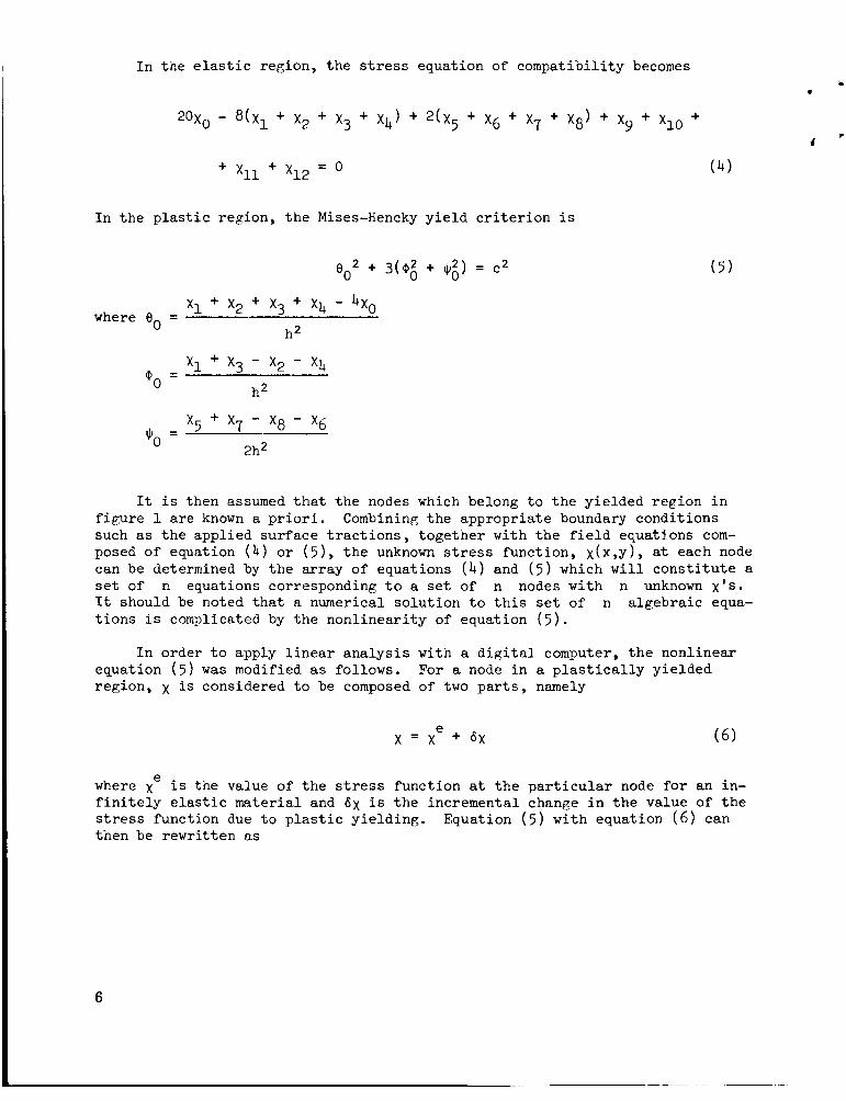
I n the e l a s t i c region, t he stress equat ion of compat ib i l i ty becomes
I n t h e p l a s t i c region, t h e Mises-Hencky y i e l d c r i t e r i o n i s
x1 + x2 + x3 + x4 - 4x0 where eo =
h2
It i s then assumed t h a t t h e nodes which belong t o t h e y ie lded reg ion i n f i g u r e 1 a r e known a p r i o r i . such as t h e appl ied su r face t r a c t i o n s , t oge the r with t h e f i e l d equatj-ons com- posed of equation ( 4 ) o r ( 5 ) , t h e unknown stress func t ion , x ( x , y ) , a t each node can be determined by t h e a r r a y of equat ions ( 4 ) and ( 5 ) which w i l l c o n s t i t u t e a se t of n equations corresponding t o a set of n nodes with n unknown x's. It should be noted t h a t a numerical so lu t ion t o t h i s set of n a lgeb ra i c equa- t i o n s i s complicated by t h e non l inea r i ty of equat ion ( 5 ) .
Combining t h e appropr ia te boundary condi t ions
I n order t o apply l i n e a r a n a l y s i s w i t h a d i g i t a l computer, t h e nonl inear equat ion ( 5 ) w a s modified as fol lows. region, x i s considered t o be composed of two p a r t s , namely
For a node i n a p l a s t i c a l l y y i e lded
e where x i s the value of t h e stress func t ion a t t h e p a r t i c u l a r node f o r an in- f i n i t e l y e l a s t i c material and 6x i s t h e incremental change i n t h e value of t h e stress funct ion due t o p l a s t i c y i e ld ing . Equation ( 5 ) w i t h equat ion ( 6 ) can then be rewr i t ten as
6

t
If &eo, 6o0 and 6t)o a r e r e l a t i v e l y small q u a n t i t i e s , then as a f i r s t approxima-
t i o n t h e square of t h e s e terms can be ignored and equation ( 7 ) becomes a l i n e a r equation i n terms of unknown q u a n t i t i e s of 6~ due t o p l a s t i c y i e ld ing a t t h e crack t i p ( r e f . 7 ) . s t r e s s funct ion a t t h e s e nodes can a l so be represented by equation ( 6 ) which upon s u b s t i t u t i n g i n t o equation (1 ) y i e l d s
Returning t o t h e e l a s t i c region, t h e new value of t h e
The approximate form of equation ( 7 ) together with equation (8) w i l l y i e l d a set of n l i n e a r a lgeb ra i c equations which can be solved f o r n unknown quanti- t i e s of 6x provided x for t h e i n f i n i t e l y e l a s t i c s o l i d i s known.
I n o rde r t o improve t h e numerical accuracy of ax, an i t e r a t i o n process w a s used. The process cons i s t ed of computing 6x repeatedly af ter previous va lues of were backsubs t i t u t ed i n t o t h e righthand s i d e of equation ( 7 ) . (See Appendix A . ) mated y i e l d region w a s c l o s e t o what could be expected and when the backsub- s t i t u t e d 6x values were c lose t o t h e f i n a l values of 6x. F r o m p r a c t i c a l con- s i d e r a t i o n s , t h e number of nonl inear nodes which could be handled s a t i s f a c t o r i - l y by t h i s procedure w a s approximately four .
6x This i t e r a t i o n process converged i n general when t h e e s t i -
Having e s t a b l i s h e d t h e four y i e l d nodes i n t h e rectangular f i e l d , a cen- t r a l po r t ion of t h i s f i e l d w a s cu t out and the g r i d d i s t ances were halved, as shown i n f i g u r e 2. The boundary condi t ions prescr ibed i n t h i s f i n e r meshed g r i d network were t h e numerical values e s t ab l i shed by t h e coa r se r g r i d which accounted f o r t h e e l a s t i c - p l a s t i c s t a t e involving fou r y i e l d nodes. With t h e f i n e g r i d network, t h e number of y i e l d nodes approximately t r i p l e d t o twelve nodes. The s t a t e of s t r e s s e s determined by t h e f i n i t e d i f f e rence method of t h i s mesh s i d e w a s considered s u f f i c i e n t l y accurate s i n c e t h e s t r e s s d i s t r i b u - t i o n by n a t u r e would not change appreciably i n the p l a s t i c y i e lded zone.
The i t e r a t i o n process used i n t h e coarse g r i a a n a l y s i s described previous- l y would not converge when appl ied t o t h e f ine g r i d a n a l y s i s d e s p i t e t h e many f r u i t l e s s e f f o r t s involved i n conditioning t h e nonl inear equations." For small incremental changes i n be cons idered second o rde r q u a n t i t i e s . ( 7 ) were d iscarded and a d i f f e r e n t i t e r a t i o n technique was performed by using the fo l lowing equation:
6x, however, t h e nonlinear terms, ( 6 0 I2 e t c . , could Thus t h e s e nonl inear 'terms i n equation
~ ~ ~ ~~~ * Numerical d i f f i c u l t i e s encountered are discussed i n reference 1 5 .
7

t . Note tha t t h e supe r sc r ip t of "e" i n equation ( 7 ) i s missing i n equat ion ( 9 ) s i n c e eo, Q0, and $, now correspond t o t h e p l a s t i c a l l y y ie lded s ta te deter-
mined by t h e coarse g r i d ana lys i s . This procedure a f t e r considerable manipula- t i o n converged t o somewhat s a t i s f a c t o r y va lues .
Another procedure attempted w a s t o s h i f t t h e g r i d network but maintain t h e mesh s i z e a t h = 1 and t o cover t h e p l a s t i c y i e l d region w i t h more nodes. The motivation f o r t h i s s h i f t e d g r i d procedure was t o cont inue t h e successfu l i t e r a t i o n procedure involving fou r y ie lded nodes on t h e assumption t h a t t h e stress d i s t r i b u t i o n did nct change appreciably i n t h e y i e l d zone. This s h i f t e d g r i d procedure which i s repor ted i n Appendix B d i d not y i e l d s a t i s f a c t o r y r e s u l t s for t .his problem.
Having e s t ab l i shed t h e necessary f i e l d equat ions s u i t a b l e f o r computer a n a l y s i s , t h e f i rs t s tep i n t h e numerical a n a l y s i s w a s t o compute t h e e las t ic e and i n i t i a l va lue of xe' f o r each problem. x f o r t h e two problems repor ted here are determined by t h e use of Westergard's stress func t ions f o r a cracked p l a t e subjected t o uniform t ens ion and uniform in-plane shear a t i n f i n i t y .
Assuming t h a t the h a l f crack length a i s s u f f i c i e n t l y l a r g e w i t h re- spec t t o the e l a s t i c - p l a s t i c region a t t h e c rack t i p i n f i g u r e 2, t h e stress func t ion x f o r a cracked p l a t e subjected t o uniform tens ion , u , i s repre- sented a s ( r e f . 9
e
where r and 0 are l o c a l p o l a r coordinates with o r i g i n at t h e crack t i p as shown i n f igu re 4. c rack length. For a p l a t e loaded w i t h uniform in-plane shear, T, t h e nor- malized s t r e s s func t ion , can be represented as
xe i s a normalized stress func t ion independent of t h e ha l f
e
If it can be f u r t h e r assumed t h a t t h e p l a s t i c r eg ion i s s u f f i c i e n t l y w i t h respect t o t h e e l a s t i c - p l a s t i c region, t hen t h e s m a l l p l a s t i c reg ion
(11)
small i n
t h e cen te r of t h e rec tangular region w i l l no t a f f e c t va lues of x' on t h e exte- r i o r boundaries of t h e region. The first s t e p i n t h e numerical procgdure then e i s t o compute x by equat ion (10) o r (11) and then p r e s c r i b e t h e s e x nodes on t h e e x t e r i o r boundaries. s i d e of t h e e x t e r i o r boundary are a l s o needed f o r f i n i t e d i f f e rence ana lys i s of a biharmonic equation.
a lone t h e xe values at l o c a t i o n one g r i d d i s t ance out-
8

Incremental Growth of E la s t i c -P la s t i c Boundary b
Having e s t ab l i shed t h e s t a t i c a l l y admissible s t r e s s f i e l d f o r one p a r t i c - u l a r load, t h e s t r e s s funct ion f o r each increment of i nc reas ing load can be e g s i l y obtained by observation of equations (10) and (11). x on t h e rectangular boundary is inve r se ly proport ional t o t h e appl ied load a or T, t h e e f f e c t of an inc rease i n u o r 'I can be accounted f o r by an appropr i a t e increase i n t h e s i z e of t h e rectangular boundaries as shown i n f ig- u r e 1. t h e same f o r a point i n t h e same p o s i t i o n r e l a t i v e t o t h e enlarged rectangular region. For a s t a t i o n a r y generic po in t i n the e l a s t i c - p l a s t i c region, t h e s t r e s s f'unction and t h e s t a t e of stress can then be determined as a funct ion of i nc reas ing load.
Since t h e prescr ibed
e 6x o r x = x + 6x as we l l as t h e e l a s t i c - p l a s t i c boundary w i l l remain
A t a generic point i n t h e e l a s t i c - p l a s t i c region, the change i n t h e stress funct ion per incremental loading of t h e n th s t e p can be represented as
Pos tu l a t ing a flow r u l e f o r t h e s t r e s s - s t r a i n r e l a t i o n i n t h e p l a s t i c a l l y y i e ld - ed region, t h e nth incremental change i n the s t r a i n s can be represented as
where E and v are e l a s t i c modulus of e l a s t i c i t y and t h e Poisson's r a t i o respec-
t i v e l y and 61'") i s an undetermined constant of flow.
from t h e s t r a i n compatibi l i ty r e l a t i o n , & A f n 9 can be determined as ( n ) ( n ) 6u , ..., and u , ... are known r m our previous ana lys i s . Also ,
9

Knowing 6,l‘”) then , it i s poss ib l e t o compute t h e four incremental s t r a i n components by equation (13) . s i n c e 6 X could not be determined with s u f f i c i e n t accuracy t o ca r ry out t h i s computation.
This po r t ion of t h e computation was not performed
Rumerical Procedure and Resul t s
The f i r s t s t e p i n t h e e l a s t i c - p l a s t i c ana lys i s i s t o y i e l d t h e most obvi- ous po in t , namely t h e node a t t h e crack t i p by es t imat ing a value of c2(nOr- malized funct ion of y i e l d stress) i n equat ion (7 ) f o r t h i s node. The remain- i ng nodes are assumed e l a s t i c and the re fo re equat ion ( 8 ) i s assigned t o t h e s e nodes and 6~ i s deteriniilsd by l i n e a r ana lys i s combined w i t h t h e i t e r a t i o n pro- cedure described previously.
If t h e material is weakened, t h e s t ra in energy s to red i n t he v i c i n i t y of t h e crack t i p i s d i s t r i b u t e d t o adjacent areas; hence, more nodes undergo y i e l d i n g and t h e p l a s t i c enclave i s enlarged. node p l a s t i c enclave, p l a s t i c enclave which includes four y i e lded nodes w a s e s t ab l i shed and a new c2 w a s es t imated , v ious ly w a s c a r r i e d o u t again with the except ion t h a t four nonl inear equat ions were used i n t h e i t e r a t i o n . The r e s u l t s of t he stress func t ions , stresses, and - c 2 computed are shown i n f i g u r e s 5 t o 10.
With t h e va lue of c2 f o r one-
The numerical method descr ibed pre-
As mentioned previously the p l a s t i c enclave could not be enlarged f u r t h e r t o take i n more y ie lded nodes, s ince t h e i t e r a t i o n procedure diverged numeri- c a l l y f o r more than four y ie lded nodes. Therefore, t h e o r i g i n a l g r i d (h = 1) w a s halved i n t o a f i n e r mesh (h = 1/2). I n o rde r t o keep t h e s i z e of t h e com- pu te r program within i t s s to rage capac i ty and t o a l low in t e rchangeab i l i t y i n computer program of one g r i d mesh t o t h e o t h e r , on ly one q u a r t e r of t h e o r i g i - n a l region was considered i n t h e f i n e g r id a n a l y s i s . Complete l i n e a r a n a l y s i s p lus successive matr ix invers ion technique i n p lace of i t e r a t i o n procedure was employed i n t h e f i n e g r i d ana lys i s . re fe rence 1 5 .
Details of t h i s procedure a r e found i n
The numerical va lues of stress func t ion t h u s obtained toge the r w i t h the stresses and c2 which were ca l cu la t ed by f i n i t e d i f f e rence are shown i n f i g u r e s 11 t o 16. 4.17, higher va lues of c2 were obta ined i n t h e p l a s t i c a l l y y i e lded region i n f i g u r e 16. procedure employed here . va lues of the stresses and t h e stress func t ion l e a d s one t o be l i eve t h a t these va lues are s u b s t a n t i a l l y co r rec t wi th in t h e f i rs t two s i g n i f i c a n t f i gu res .
Although t h e assigned maximum va lue of c2 f o r t h i s c a l c u l a t i o n w a s
This discrepancy somewhat i n d i c a t e s t h e inadequacy of t h e numerical Despi te t h i s discrepancy, t h e s u f f i c i e n t l y continuous
Cracked P l a t e Subjected t o Uniform In-Plane Shearing
Except f o r equat ion (11) , s i m i l a r numerical procedures as descr ibed above were used t o determine the stress func t ion , stresses, and c2 d i s t r i b u t i o n i n t h e coarse and f ine g r i d ana lyses , Figures 17 through 22 and f i g u r e s 23 throuRh 28 show these d i s t r i b u t i o n s f o r rep;ions w i t h g r i d spacing; of h = 1 and a subregion w i t h a Kr id spacing of h = 1/2. - c 2 and t h e assigned maximum value of 5’ = 2.87 i s t o be noted i n f i g u r e 28.
Again t h e discrepancy between t h e c a l c u l a t e d
10
b .

DISCUSSION
I These values a r e a l s o t abu la t ed i n Tables I and 11.
-112 From t h e above r e s u l t s it can be seen t h a t t h e s t r e s s s i n g u l a r i t y of r i s e s s e n t i a l l y maintained at a small d i s t ance away from t h e crack t i p and t h e r e a f t e r . Thus, t h e s t a t e s of s t r e s s e s i n t h e s e two problems can be repre- sented i n t h e form of equation (10) o r (11) w i t h a magnification f a c t o r of 1.05 t o 1.10 f o r regions ahead of t h e crack t i p s . shown i n f i g u r e s 33 and 34.
De ta i l s of t h e l a t t e r values are
As noted i n t h e first s e c t i o n , t h e i n t e n t i o n of t h i s i n v e s t i g a t i o n w a s t o I e s t a b l i s h a d u c t i l e f r a c t u r e c r i t e r i o n . With t h e i n t e n t i o n of extending t h e ' Gri f f i t h - I rwin theory of f r a c t u r e i n t o d u c t i l e f r a c t u r e following I rwin ' s y i e l d
co r rec t ion f a c t o r , t h e numerical r e s u l t s were compared w i t h equivalent e l a s t i c r e s u l t s .
Figures 29 through 32 show t h e stress function versus radial d i s t ances from t h e crack t i p f o r t h e two problems, These f igu res show t h a t on a log-log p l o t , t h e s t r e s s func t ion remains e s s e n t i a l l y a s t r a i p h t l i n e w i t h a s lope of c lose t o m = 1.5. The values of m - 2 represent the negative power of r o r t h e order i n which t h e s t r e s s e s inc rease as they approach t h e crack t i p . Tables I and I1 show t h e s lopes of t h e s e l i n e s f i t t e d through po in t s i n f i g u r e s 29 through 32 by t h e method of l e a s t square. Normalized pseudo s t r e s s i n t e n s i t y f a c t o r s were then determined from these f i t t e d l i n e s as
-m r x -1
3 2
f o r uniform t ens ion (15 ) 51= 1 30 e - cos 2. cos -
Irwin proposed t h a t t h e p l a s t i c i t y e f f e c t can be handled by increasing t h e n
) UL
4 f i 4k2 e f f e c t i v e crack l e n g t h f o r the s ta te of plane stress from a t o a (1 +
( r e f . 2 ) . t e n s i o n problem w i l l be
The s t r e s s i n t e n s i t y f a c t o r determined by I rwin ' s co r rec t ion f o r t h e
For a nominal loading condi t ion of z= 0.7, eq.uation (17) y i e l d s K = 1.05 2k which i s i n t h e realm of t h e co r rec t ion f a c t o r obtained by t h i s ana lys i s .
11

APPENDIX A
A flow c h a r t of t h e computer proaram i s shown on t h e next page t o h e l p t o v i s u a l i z e the i t e r a t i o n procedure described i n t h e main t e x t .
12

FLOW CHART: -- - S t a r t
(Read X,Y ( rectangular coordinates ,>
e Calculate e l a s t i c stress func t ion x
Calculate Be, ke, ke from xe by f i n i t e difference methods (yielded nodes on ly )
Do K = 1, 30 i t e r a t i o n process begins
i
Calculate 66, 6&, 6 d i f f e rence methods t yie lded nodes only)
from S x by f i n i t e
{MI = 0 . }-------b [BB] = 0. OR V4xe = 0.
(Read pre-estimated 29 t t
[BB] of t h e y i e lded node by Mises-Hencky's y i e l d c r i t e r i o n , e.g.,
[BB] = 1 / 2 [ L ~ - - e2 - 3(k2 + k2) - (&&I2 - 3{(6&12 + (6&)2}1
13

Read {AA) of t h e non-yielded nodes, where {AA) are t h e co- e f f i c i e n t s (V4) of t h e b ihar - monic equations ( ~ 4 6 ~ = 0.)
d
v
* I{AA) of t h e yielded nodes where1
process diverge
. C a l l subrout ine m a t r i x 1
Calculate necessary a a a T a n d 2 2 x x ’ x ’ xy’ m a x - from x by f i n i t e d i f f e rence methods
14

APPENDIX B
The procedure which appeared moderately successful w a s t h e procedure of 8 t h e s h i f t i n g of t h e coarse f i n i t e d i f f e rence g r i d . By p a r a l l e l and perpendic-
u l a r s h i f t i n g of t h e coarse g r i d i n t h e region, it i s poss ib l e t o ob ta in an est imate of t h e s t r e s s func t ion a t any p a r t i c u l a r point i n t h e region. T h i s procedure has t h e advantage of assured convergence because t h e number of plas- t i c a l l y y i e lded nodal po in t s w a s confined t o approximately four o r f i v e po in t s . Obviously, t h e use of such coarse f i n i t e d i f f e rence g r i d could y i e l d only aver- age values of t h e s ta te of s t r e s s e s . Fluctuat ions of t h e state of s t r e s s e s i n t h e p l a s t i c a l l y yielded region were be l ieved t o be s u f f i c i e n t l y small such t h a t t h e r e s u l t s t h u s obtained could not be i n substant ia l . e r r o r .
Figures 35 and 36 show s t r e s s component u and - c 2 computed by t h i s pro- 3
cedure. A s self evident , t h e s t a t e of s t r e s s e s determined by t h i s procedure w a s not s u f f i c i e n t l y smooth and continuous t o continue wi th t h i s procedure. It i s bel ieved, however, t h a t t h e s h i f t e d g r i d approach could f i n d a p p l i c a t i o n i n o t h e r e l a s t i c - p l a s t i c problems with r e l a t i v e l y small s t r e s s g rad ien t s .
15

APPENDIX C
Another approach was t o use s t a b l e numerical r e s u l t s obtained by t h e coarse g r id f i n i t e d i f f e rence network f o r t h e stress d i s t r i b u t i o n and t o devel- op a curve f i t t i n g procedure t o t h e s t r a i n funct ion sepa ra t e ly . In an e l a s t i c - p l a s t i c ana lys i s where t h e stress s i n g u l a r i t y i s removed, it seems reasonable t o assume t h a t t h e s ta te of stresses w i l l not vary r ap id ly and t h e r e f o r e t h e s t a t e of stresses obtained by a coarse f i n i t e d i f f e rence g r i d network should be a f a i r r ep resen ta t ion of t h e t r u e s t a t e of s t r e s s e s . would thus be determined by l i n e a r i n t e r p o l a t i o n of t h e r e s u l t s obtained by t h e coarse g r id work.
The state of s t r e s s e s
The straki function, which w i l l r ep resen t t h e t o t a l s t r a i n a t a l l p o i n t s , must be biharmonic from t h e compatibi l i ty of t h e t o t a l s t r a i n s . s t r e s s funct ion, x, which i s biharmonic and which satisfies t h e following r e l a t i o n ,
For an Airy
YY uxx = X I X’XX u =
YY Xy u = -x ,
Xy
a s i m i l a r s t r a i n funct ion can be determined as
- V * W , I xx E yy xx 1
E = - [ w ,
I n t h e e l a s t i c region, t h e s t r a i n funct ion as def ined above w i l l coincide with t h e stress funct ion o r x = w. ever, t h e two funct ions w i l l d i f f e r .
I n t h e p l a s t i c a l l y y i e lded region, how-
A p l o t of s t r e s s funct ion obtained from t h e f i n i t e d i f f e rence a n a l y s i s with respect t o d i s t ance , r , from t h e crack t i p , shows t h a t poss ib ly
1 1 w(r , e ) = w (-1 w ( e ) + w2 (-) ~ ~ ( 8 ) JF l r 1
i n t h e e l a s t i c region. c a l l y yielded region, a s t r a i n funct ion which i s equal t o t h e s t r e s s funct ion i n t h e e l a s t i c region could be determined.
Assuming t h a t t h e same t r e n d holds t r u e i n t h e p l a s t i -
16

Appendix C (.cont 'd. I
"he state of s t r a i n w a s determined from t h i s s t r a i n funct ion and checks were made if t h e Prandtl-Reuss flow r u l e can be s a t i s f i e d between t h e states of stresses and strains t h u s determined. The r e s u l t s turned ou t t o be nega- t i v e and t h i s approach was a l so abandoned.
17

REFERENCES
1. I r w i n , G. R . : Fracture . Vol. 6 ( E l a s t i c i t y and P l a s t i c i t y ) Handbuch der Physik, Springer ( B e r l i n ) , 1958, pp. 551-590.
2. I r w i n , G. R.: F rac ture Test ing of High St rength Sheet Materials. ASTM Bul le t in , Jan . 1960, pp. 29-40.
3. W i l l i a m s , M. L.: Some Observations Regarding t h e S t r e s s F ie ld N e a r t h e Point of a Crack. England, Sept . 1961.
Proc. of t h e Crack Propagation Symposium, Cranfield,
Also: A Review of Recent Research a t GALCIT Concerning F rac tu re I n i t i a - t i on . Aero. Research Lab. TN, Apr i l 1961.
4 . McClintock, F. A , : Duct i le Frac ture I n s t a b i l i t y i n Shear. J. of Appl. Mech., vo l . 25, no. 4 , Dec. 1958, pp. 582-588.
5. Val lur i , S. R.: A Theory of Cumulative Damage i n Fat igue. Aero. Research Lab. TN, Jan . 1961.
6. Liu, H. W.: Fat igue Crack Propagation and Applied S t r e s s Range--An Energy Approach, J. of Basic Eng., vo l . 8 5 , series D, no. 1, March 1963, pp. 116-122.
7. Stimpson, L. D.; and Eaton, D. M.: The Extent of E la s t i c -P la s t i c Yielding a t t h e Crack Point of an Externa l ly Notched Plane S t r e s s Tens i l e Specimen. GugRenheim Aero. Lab. o f C a l , I n s t i t u t e of Tech. Report SM 60-10, June 1960.
8. Swedlow, J. L.; Williams, M. L . ; and Yang, W. H. : E las to-Plas t ic S t r e s s e s and S t r a i n s i n Cracked P l a t e s . Proc. of I n t ' l . Conf. on Frac ture , Sendai, Japan, Sept . 1965.
9. Allen, D. N . de G . ; and Southwell, R. V.: P l a s t i c S t r a i n i n g i n Two- Dimensional S t r e s s Systems. Philosoph. Trans. of t h e Roy. Soc. (London), s e r i e s A, vol . 242, June 1950, pp. 379-414.
10. Jacobs, J. A.: Relaxat ion Methods Applied t o Problems of P l a s t i c Flow I, Notched B a r under Tension. Philosoph. Mag., vo l . 41, 1950, pp. 349-361.
11. H u l t , J . A. H.: Fat igue Crack Propagation i n Torsion. J . of t h e Mech. and Physics of Sol ids , vo l . 6, 1957, pp. 47-52.
12 . Rice, J. R.: S t r e s ses Due t o Sharp Notch i n a Work Hardening Elastic- P l a s t i c Mater ia l Loaded by Longi tudinal Shear , Brown Univ. TR, Dec. 1956.
13. Koskinen, M. F.: E las t ic P l a s t i c Deformation of a S ing le Grooved F l a t P l a t e under Longitudinal Shear , Winter Annual Meeting: of ASME, Nov. 25-30, 1965.
ASME paper no. 62-WA-137, Presented a t
18

14. Roberts, E., Jr.; and Mendelson, A.: Analysis of Plastic Thermal Stresses and Strains in Finite Thin Plate of Strain Hardening Mater- ial. NASA TN D-2206, Oct . 1964. &
15. W o o , Savio: Elastic Plastic Analysis in the Vicinity of a Crack Tip. 8 Univ. of Washington, MS Thesis, Dec. 1966.
19

0
TABLE I-a
UNIFORM T E N S I O N LOADING
COARSE G R I D
m $1
0' 1.36
1.45
45.0' 1.50
2b, 6"
63.4' 1.53
90.0' 1.58
116.6' 1.74
135.0' 2.19
1.19
1.18
1.12
1.03
.965
,744
.281
TABLE I-b
UNIFORM T E N S I O N LOADING
FINE G R I D
K 0 m %I
0' 1.35
26.6' 1.40
45.0' 1.46
63.4' 1.50
90. 0' 1.59
116.6' 1.75
135.0' 1.93
1.08
1.16
1.17
1.06
.969
,794
.562
20

. TABLE 11-a
UNIFORM IN-PLANE SHEAR LOADING
COARSE GRID
e m E11
~~ ~
26.6' 1.41 1.14
4 5' 1.42 1.13
63.4' 1.42 1.11
90' 1.38 1.17
116.6' 1.40 1.15
13 5O 1.40 1.18
153.4' 1.43 1.14
TABLE 11-b
UNIFORM IN-PLANE SHEAR LOADING
FINE GRID
e m
26.6' 1.35
4 5O 1.44
63.4' 1.45
90' 1.40
116.6' 1.44
135' 1.42
153.4' 1.33
1.18
1.07
1.07
1.08
1.09
1 .ll
1.28
21

FIGURE 1 . GROWTH OF ELASTIC-PLASTIC BOUNDARY WHEN MATERIAL IS WEAKENED WITH CONSTANT APPLIED LOAD
FIGURE 2 . FINITE DIFFERENCE GRID IN THE VICINITY OF A CRACK TIP

FIGURE 3. NODAL LOCATION FOR BI- HARMONIC FINITE DIFFER- ENCE OPERATOR
FIGURE 4 . LOCAL POLAR COORDINATES IN THE VICINITY OF A CRACK TIP
23

FIGURE 5. XI DISTRIBUTION IN CRACKED PLATE SUBJECTED TO UNIFORM TENSION ELASTIC-PLASTIC BOUNDARY AT G* ~3.25
COARSE GRID (GRID LENGTH h m I I
FIGURE 6. DISTRIBUTION IN CRACKED PLATE SUWECTED TO UNIFORM TENSION ELASTIC-PLASTIC BOUNDARY AT g* = 3.25
COLME WID (GRID LENGTH h - I I
24

FIGURE 7. Fn DISTRIBUTION IN CRACKED PLATE SUBJECTED TO UNIFORM TENSION ELASTlC-Fi-ASTIC BOUNLW?Y AT s2 = 3.25
M I R S E GRID (GRID LvlGTH h = I 1
FIGURE 8. Pzy MSTRIBUTON IN CRACKED U T E SUBJECTED TO UNIFORM TENSION ELASTIC-RASTIC BWNDARI AT f2=3.25
tOaRSE WID (GRIDLENGTH h * l l
25

FIGURE 9. I m o r DISTRIBUTION IN CRACKED PLATE SUBJECTED TO UNIFORM TENSION ELASTIC-FUSTIC BOUNDARY AT E'; 3.25
CWRSE GRID IGRID LENOTH h * I ) ; SCUD LINES * EUSTIC-RbSlK M L S l S ; DIsnDD LlwEs - -IC ANALIYS
FIGURE IO. DISTRIBUTION IN CRACKED PLATE SUBJECTED TO UNIFORM TENSON ELASTIC-PLASTIC BOUNDARY AT s2.3.a
COIML GRID IORlD LENGTH h . I I
26

27

28

.
29

m F m - m m Ln -. - 9 C
.i f m -. 9 C
N rl In
I I -, C
ul a, N
I I t
ul -. '
m 4 N
I I I
m.
m f m
I I -.
.i f y\
I I I
nl-
W 0 f
I I
-4 1
I

,
31

32

FIGURE 17. & I DISTRIBUTION IN CRACKED PLATE SUBJECTED TO UNIFORM IN-PLANE SHEAR
ELASTIC-PLASTIC BOUNDARY AT c2 = 1.57 COARSE GRID (GRID LENOM h a 1 1
FIGURE 18. Fxx DISTRIBUTION IN CRACKED PLATE SUBJECTED TO UNIFORM IN-PLANE SHEAR ELASTIC-PLASTIC BOUNDARY AT c2= 1.57
COARSE ORlP (GRID LENGTH h = I 1
33

FIGURE 20. F x y DISTRIBUTION IN CRACKED PLATE SUBJECTED TO UNIFORM IN-PLANE SHEAR ELASTIC-PLASTIC BOUNDARY AT 1.57.
COARSE GRID (GRID LENGTH h - I 1
34
FIGURE 19. gyy DISTRIBUTION IN CRACKED PLATE SUBJECTED TO UNIFORM IN-PLANE SHEAR ELASTIC-PLASTIC BOUNDARY AT E* = 1.57
COARSE GRID (GRID LENGTH h = I )

FIGURE 21. I m a x DISTRIBUTION IN CRACKED PLATE SUBJECTED TO UNIFORM IN-PLANE SHEAR ELASTIC-PLASTIC BOUNDARY AT c2 = 1.57
COARSE GRID (GRID LENGTH h = I ) ; SOLID LINES ELASTIC-PLASTIC ANALYSIS ; MSHED LINES U A S n C ANALYSIS
.42 .44 .47 .47 .46 .41 .36 .33 .35 .3a .39 .39 .36
.47 .44
FIGURE 22. c2 DISTRIBUTION IN CRACKED PLATE SUBJECTED TO UNIFORM IN-PLANE SHEAR ELASTIC-PLASTIC BOUNDARY AT c2 = 1.57
COARSE GRID (GRID LENGTH h * l
35


.
37

38

39

40

41

.I .2 .4 .6 .8 I 2 4 6 8 1 0
RADIAL DISTANCE r/h 20
FIGURE 29. STRESS FUNCTIONS (XI) - vs RADIAL DISTANCES ( r/h WHERE h = I 1
COARSE GRID , c2m 3.25
42

. I .2 .4 .6 .8 I 2 4 6 810 20 RADIAL DISTANCE r/h
FIGURE 30. STRESS FUNCTIONS (XI) vs RADIAL DISTANCES (r/h WHERE h = I )
FINE GRID , g2a 4.17
43

. I .2 .4 .6 .8 I 2 4 6 8 1 0 20 RADIAL DISTANCE r/h
flGURE 31. STRESS FUNCTIONS M,,) - vs RADIAL DISTANCES (r/h WHERE h=l )
COARSE GRID, e2' 1.57
44

' C 40E
.I .4 RADIAL DISTANCE r/h
8 = 26.6O 0 45.0° A 63.4O 0 90.0° 0
135.0° A 153.4O
I 16.60
E L - IO 20
FIGURE 32. STRESS FUNCTIONS (XI,) vs RADIAL DISTANCES (r/h WHERE h= I 1 FINE GRID , z2= 2.87
4 5

c PLASTIC ANALYSIS - FINE GRID PLASTIC ANALYSIS COARSE GRID \
FIGURE 33. VALUES OF E, AT VARIOUS ANGLES.
PLASTIC ANALYSIS COARSE GRID
EL ANALYSIS \ a <
PLASTIC ANALYSIS
/
FIGURE 34. VALUES OF Ell AT VARIOUS ANGLES
46

FIGURE 35. Cn DISTRIBUTION IN CRACKED PLATE SUBJECTED TO UNIFORM TENSION ELASTIC-WASTIC BOUNDARY AT c2= 2.15
SOLID LINES ORIGINAL GRID ; DASMED LINES * SHIFTED GRID
FIGURE 36. s2 DISTRIBUTION IN CRACKED PUJE SUBJECTED TO UNIFORM TENSION ELASTIC-PLASTIC BWNDARY AT s2= 2.15
SOLID LINES = ORIGINAL GRID ; CJASMED LINES SMIFTED GRID
NASA-Langley, 1967 - 32 CR-772 47

"The aeromticd and space activities of the United States shall be conducted so as to contribute . , . to tbe expansion of brrman ;kaowl- edge of pbenomena in the atmosphere and space. The Administration rbali provide for tbe widest practicable and appropriate dissemination of information concerning its activities and tbe results tbereof."
-NATIONAL h R O N A U n C S AND SPACB fkl' OF 1958
NASA SCIENTIFIC AND TECHNICAL PUBLICATIONS
TECHNICAL REPORTS: Scientific and technical information considered important, complete, and a lasting contribution to existing knowle&e.
TECHNICAL NOTES: Information less broad in scope but nevertheless of importance as a contribution to existing knowledge.
TECHNICAL MEMORANDUMS: Information receiving limited distribu- tion because of preliminary data, security classification, or other reasons.
CONTRACI'OR REPORTS: Scient& and technical information generated under a NASA contract or grant and considered an important contribution to existing knowledge.
TECHNICAL TRANSLATIONS: Information published in a foreign language considered to merit NASA distribution in English.
SPECIAL PUBLICATIONS: Information derived from or of value to NASA activities. Publications include conference proceedings, monographs, data compilations, handbooks, sourcebooks, and special bibliographies.
TECHNOLOGY UTILIZATION PUBLICATIONS: Information on tech- nology used by NASA that may be of particular interest in commercial and other non-aerospace applications. Publications include Tech Briefs, Technology Utilization Reports and Notes, and Technology Surveys.
,
Details on the availability of these publications may be obtained from:
SCIENTIFIC AND TECHNICAL INFORMATION DIVISION
NATIONAL AERONAUTICS AND SPACE ADMINISTRATION
Washingon, D.C PO546